EP2201890B1 - Catheter display showing tip angle and pressure - Google Patents
Catheter display showing tip angle and pressureDownload PDFInfo
- Publication number
- EP2201890B1 EP2201890B1EP09252879AEP09252879AEP2201890B1EP 2201890 B1EP2201890 B1EP 2201890B1EP 09252879 AEP09252879 AEP 09252879AEP 09252879 AEP09252879 AEP 09252879AEP 2201890 B1EP2201890 B1EP 2201890B1
- Authority
- EP
- European Patent Office
- Prior art keywords
- probe
- pressure
- catheter
- icon
- bend angle
- Prior art date
- Legal status (The legal status is an assumption and is not a legal conclusion. Google has not performed a legal analysis and makes no representation as to the accuracy of the status listed.)
- Active
Links
- 239000000523sampleSubstances0.000claimsdescription22
- 238000000034methodMethods0.000claimsdescription21
- 210000002216heartAnatomy0.000claimsdescription16
- 238000005259measurementMethods0.000claimsdescription7
- 238000003780insertionMethods0.000claimsdescription6
- 230000037431insertionEffects0.000claimsdescription6
- 210000000056organAnatomy0.000claimsdescription3
- 230000002107myocardial effectEffects0.000claims2
- 210000001519tissueAnatomy0.000description18
- 230000001225therapeutic effectEffects0.000description7
- 210000001174endocardiumAnatomy0.000description6
- 238000002679ablationMethods0.000description5
- 230000008878couplingEffects0.000description5
- 238000010168coupling processMethods0.000description5
- 238000005859coupling reactionMethods0.000description5
- 238000009530blood pressure measurementMethods0.000description3
- 210000005242cardiac chamberAnatomy0.000description3
- 238000002405diagnostic procedureMethods0.000description3
- 210000005003heart tissueAnatomy0.000description3
- 238000013507mappingMethods0.000description3
- 230000007246mechanismEffects0.000description3
- 238000002560therapeutic procedureMethods0.000description3
- 230000000007visual effectEffects0.000description3
- 230000000747cardiac effectEffects0.000description2
- 230000006378damageEffects0.000description2
- 238000006073displacement reactionMethods0.000description2
- 230000006870functionEffects0.000description2
- 230000004044responseEffects0.000description2
- 230000002792vascularEffects0.000description2
- 210000000709aortaAnatomy0.000description1
- 238000005452bendingMethods0.000description1
- 210000004204blood vesselAnatomy0.000description1
- 238000004040coloringMethods0.000description1
- 230000000295complement effectEffects0.000description1
- 229910003460diamondInorganic materials0.000description1
- 239000010432diamondSubstances0.000description1
- 230000012447hatchingEffects0.000description1
- 238000012986modificationMethods0.000description1
- 230000004048modificationEffects0.000description1
- 238000012544monitoring processMethods0.000description1
- 210000004165myocardiumAnatomy0.000description1
- 230000003287optical effectEffects0.000description1
- 230000008569processEffects0.000description1
- 238000007674radiofrequency ablationMethods0.000description1
- 230000000451tissue damageEffects0.000description1
- 231100000827tissue damageToxicity0.000description1
Images
Classifications
- A—HUMAN NECESSITIES
- A61—MEDICAL OR VETERINARY SCIENCE; HYGIENE
- A61B—DIAGNOSIS; SURGERY; IDENTIFICATION
- A61B5/00—Measuring for diagnostic purposes; Identification of persons
- A61B5/06—Devices, other than using radiation, for detecting or locating foreign bodies ; Determining position of diagnostic devices within or on the body of the patient
- A61B5/061—Determining position of a probe within the body employing means separate from the probe, e.g. sensing internal probe position employing impedance electrodes on the surface of the body
- A61B5/062—Determining position of a probe within the body employing means separate from the probe, e.g. sensing internal probe position employing impedance electrodes on the surface of the body using magnetic field
- A—HUMAN NECESSITIES
- A61—MEDICAL OR VETERINARY SCIENCE; HYGIENE
- A61B—DIAGNOSIS; SURGERY; IDENTIFICATION
- A61B5/00—Measuring for diagnostic purposes; Identification of persons
- A61B5/68—Arrangements of detecting, measuring or recording means, e.g. sensors, in relation to patient
- A61B5/6846—Arrangements of detecting, measuring or recording means, e.g. sensors, in relation to patient specially adapted to be brought in contact with an internal body part, i.e. invasive
- A61B5/6885—Monitoring or controlling sensor contact pressure
- A—HUMAN NECESSITIES
- A61—MEDICAL OR VETERINARY SCIENCE; HYGIENE
- A61B—DIAGNOSIS; SURGERY; IDENTIFICATION
- A61B5/00—Measuring for diagnostic purposes; Identification of persons
- A61B5/74—Details of notification to user or communication with user or patient; User input means
- A61B5/742—Details of notification to user or communication with user or patient; User input means using visual displays
- A61B5/743—Displaying an image simultaneously with additional graphical information, e.g. symbols, charts, function plots
- A—HUMAN NECESSITIES
- A61—MEDICAL OR VETERINARY SCIENCE; HYGIENE
- A61B—DIAGNOSIS; SURGERY; IDENTIFICATION
- A61B34/00—Computer-aided surgery; Manipulators or robots specially adapted for use in surgery
- A61B34/20—Surgical navigation systems; Devices for tracking or guiding surgical instruments, e.g. for frameless stereotaxis
- A61B2034/2046—Tracking techniques
- A61B2034/2051—Electromagnetic tracking systems
Definitions
- the present inventionrelates generally to invasive medical devices, and specifically to methods and devices for displaying characteristics of a probe, such as a catheter, inside the body of a patient.
- a catheteris inserted into a chamber of the heart and brought into contact with the inner heart wall.
- a catheter having an electrode at its distal tipis inserted through the patient's vascular system into a chamber of the heart.
- the electrodeis brought into contact with a site (or sites) on the endocardium, and RF energy is applied through the catheter to the electrode in order to ablate the heart tissue at the site.
- RF energyis applied through the catheter to the electrode in order to ablate the heart tissue at the site.
- U.S. Patent Application Publication 2007/0100332describes systems and methods for assessing electrode-tissue contact for tissue ablation.
- An electro-mechanical sensor within the catheter shaftgenerates electrical signals corresponding to the amount of movement of the electrode within a distal portion of the catheter shaft.
- An output devicereceives the electrical signals for assessing a level of contact between the electrode and a tissue.
- U.S. Patent 6,695,808describes apparatus for treating a selected patient tissue or organ region.
- a probehas a contact surface that may be urged against the region, thereby creating contact pressure.
- a pressure transducermeasures the contact pressure.
- PCT International Publication WO 2007/067938describes a method for displaying catheter electrode-tissue contact in an electro-anatomic mapping and navigation system.
- the systemprovides an indication to the physician concerning the electrical coupling of an electrode, such as an ablative or mapping electrode, with a patient.
- the indicationmay be provided by changing the color or other display characteristics of the electrode on the navigation system display or by way of providing a waveform indicating the electrode coupling. This manner of providing electrode coupling information is said to minimize physician distraction.
- the embodiments of the present inventionthat are described hereinbelow provide novel means for displaying parameters associated with the quality of engagement between an invasive probe and tissue within the body of a subject.
- This sort of displaycan assist the operator of the probe in visualizing the situation of the probe and thus in ensuring the effectiveness and safety of diagnostic and/or therapeutic procedures that are performed using the probe.
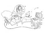
- Fig. 1is a schematic, pictorial illustration of a system 20 for cardiac catheterization, in accordance with an embodiment of the present invention.
- System 20may be based, for example, on the CARTOTM system, produced by Biosense Webster Inc. (Diamond Bar, California).
- This systemcomprises an invasive probe in the form of a catheter 28 and a control console 34.
- catheter 28is used in ablating endocardial tissue, as is known in the art.
- the cathetermay be used mutatis mutandis, for other therapeutic and/or diagnostic purposes in the heart or in other body organs.
- the operatoradvances the catheter so that the distal tip of the catheter engages endocardial tissue at a desired location or locations.
- Catheter 28is typically connected by a suitable connector at its proximal end to console 34.
- the consolecomprises a radio frequency (RF) generator 40, which supplies high-frequency electrical energy via the catheter for ablating tissue in the heart at the locations engaged by the distal tip, as described further hereinbelow.
- the catheter and systemmay be configured to perform ablation by other techniques that are known in the art, such as cryo-ablation.
- the catheter and systemmay be used to perform other sorts of therapeutic and/or diagnostic procedures, such as electro-anatomical mapping.
- Console 34uses a position sensing technique to determine position coordinates of distal end 30 of catheter 28 inside heart 22.
- the consoleuses magnetic position sensing, which is also used in deriving angle and pressure information with respect to the distal end, as described further hereinbelow.
- the principles of the present inventionmay be applied using other position sensing and pressure sensing techniques, as are known in the art.
- a driver circuit 38 in console 34drives field generators 32 to generate magnetic fields within the body of patient 24.
- the field generatorscomprise coils, which are placed below the patient's torso at known positions external to the patient. These coils generate magnetic fields in a predefined working volume that contains heart 22.
- a magnetic field sensor within distal end 30 of catheter 28(not shown in the figures) generates electrical signals in response to these magnetic fields.
- a signal processor 36processes these signals in order to determine the position coordinates of the distal end, typically including both location and orientation coordinates.
- Processor 36typically comprises a general-purpose computer, with suitable front end and interface circuits for receiving signals from catheter 28 and controlling the other components of console 34.
- the processormay be programmed in software to carry out the functions that are described herein.
- the softwaremay be downloaded to console 34 in electronic form, over a network, for example, or it may be provided on tangible media, such as optical, magnetic or electronic memory media.
- some or all of the functions of processor 36may be carried out by dedicated or programmable digital hardware components.
- processor 36drives a display 42 to give operator 26 visual feedback regarding distal end 30 of catheter 28 in the patient's body, as well as status information and guidance regarding the procedure that is in progress.
- the visual feedbackshows the pressure on the distal end, as well as the bend angle of the distal tip of the catheter, as is described further hereinbelow with reference to Fig. 3 .
- system 20may comprise an automated mechanism for maneuvering and operating catheter 28 within the body of patient 24.
- Such mechanismsare typically capable of controlling both the longitudinal motion (advance/retract) of the catheter and transverse motion (deflection/steering) of the distal end of the catheter.
- Some mechanisms of this sortuse DC magnetic fields for this purpose, for example.
- processor 36generates a control input for controlling the motion of the catheter based on the signals provided by the magnetic field sensor in the catheter. As noted earlier, these signals are indicative of both the position of the distal end of the catheter and force exerted on the distal end.
- the pressure and bend angle shown on display 42may be used by a human operator in monitoring the status and progress of the automated procedure.
- Fig. 2is a schematic sectional view of a chamber of a heart 22, showing distal end 30 of catheter 28 inside the heart, in accordance with an embodiment of the present invention.
- the cathetercomprises an insertion tube 60, which is typically inserted into the heart percutaneously through a blood vessel, such as the vena cava or the aorta.
- An electrode 50 on a distal tip 52 of the catheterengages endocardial tissue 70. Pressure exerted by the distal tip against the endocardium deforms the endocardial tissue locally, so that electrode 50 contacts the tissue over a relatively large area.
- the electrodeengages the endocardium at an angle, rather than head-on.
- Distal tip 52therefore bends at a resilient joint 56 relative to the distal end of insertion tube 60 of the catheter. The bend may facilitate optimal contact between the electrode and the endocardial tissue.
- the angle of bending and the axial displacement of the jointare proportional to the pressure exerted by tissue 70 on distal tip 52 (or equivalently, the pressure exerted by the distal tip on the tissue). Measurement of the deformation of the joint, in terms of bend angle and axial displacement, thus gives an indication of this pressure.
- the pressure indicationmay be used by operator 26 of system 20 in ensuring that the distal tip is pressing against the endocardium firmly enough to give the desired therapeutic or diagnostic result, but not so hard as to cause undesired tissue damage.
- Joint 56may comprise a superelastic coupling member, as described in U.S. Patent Application 12/134,592, filed June 6, 2008 .
- the coupling membermay comprise a coil spring or any other suitable sort of resilient component with the desired flexibility and strength characteristics.
- U.S. Patent Application 12/327,226, filed December 3, 2008describes an arrangement of magnetic coils within the distal end of the catheter that can be used in sensing the tip angle and pressure with enhanced accuracy. Both of these two patent applications are assigned to the assignee of the present patent application.
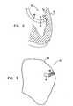
- Fig. 3is a schematic representation of a map 80 of a heart chamber, which includes an icon 84 corresponding to distal end 30 of catheter 28, in accordance with an embodiment of the present invention.
- a map of this sortis typically presented on display 42, as an aid to operator 26 in visualizing the distal end of the catheter within heart 22.
- the mapincludes a graphical representation of an inner surface 82 of the heart chamber in which the distal end of the catheter is located. (Surface 82 may be fully reconstructed, as shown in Fig. 3 , or only partially reconstructed.)
- the position of icon 84 relative to surface 82gives the operator an indication of the location of the actual distal end of the catheter in the heart chamber.
- Icon 84shows not only the location of distal end 30, but also angular and pressure characteristics.
- the iconis articulated to show the measured bend angle of distal tip 52 relative to insertion tube 60. If the operator sees that the distal tip of the catheter is sharply bent, for example, he or she may readjust the position of the catheter before continuing with a diagnostic or therapeutic procedure, such as ablating the heart tissue.
- At least a portion 86 of the iconmay be colored (represented in the figure by hatching) to indicate the pressure. For example, green coloring may indicate that the pressure is within the correct pressure range for RF ablation, while red indicates too much pressure, and blue indicates too little.
- the pressure rangesmay be preset, or they may be adjusted by the operator. In either case, the operator will then apply the RF energy only when the pressure is within the range that will give the desired therapeutic result.
- the graphical display of pressure and bend angle by icon 84gives the operator additional visual information that is not provided by display techniques that are known in the art. This additional information can be useful as a complement to or in place of measurement of electrode/tissue electrical contact resistance.
- the pressure and/or angle display itselfis important, for example, under the following circumstances:
- icon 84 in Fig. 3represents both tip angle and pressure parameters, in addition to location of the catheter tip, the examples above show that it can be useful to display either the angle or the pressure by itself, this does, however, not form part of the claimed invention.
- one or both of the angle and pressure measurementsmay be displayed together with a measurement of electrical contact resistance or other parameters.
- Fig. 3shows a particular mode of graphical representation, other techniques for displaying angle and pressure data will be apparent to those skilled in the art and are considered to be within the scope of the present invention.
- the display techniques that are described or suggested hereinabovemay be used not only in cardiac catheterization procedures, but also in other types of invasive diagnostic and therapeutic applications.
Landscapes
- Health & Medical Sciences (AREA)
- Life Sciences & Earth Sciences (AREA)
- Engineering & Computer Science (AREA)
- Molecular Biology (AREA)
- Animal Behavior & Ethology (AREA)
- Biophysics (AREA)
- Pathology (AREA)
- Biomedical Technology (AREA)
- Heart & Thoracic Surgery (AREA)
- Medical Informatics (AREA)
- Veterinary Medicine (AREA)
- Surgery (AREA)
- Physics & Mathematics (AREA)
- General Health & Medical Sciences (AREA)
- Public Health (AREA)
- Human Computer Interaction (AREA)
- Nuclear Medicine, Radiotherapy & Molecular Imaging (AREA)
- Radiology & Medical Imaging (AREA)
- Surgical Instruments (AREA)
- Media Introduction/Drainage Providing Device (AREA)
- Measurement And Recording Of Electrical Phenomena And Electrical Characteristics Of The Living Body (AREA)
- Measuring And Recording Apparatus For Diagnosis (AREA)
- Measuring Pulse, Heart Rate, Blood Pressure Or Blood Flow (AREA)
Description
- The present invention relates generally to invasive medical devices, and specifically to methods and devices for displaying characteristics of a probe, such as a catheter, inside the body of a patient.
- In some diagnostic and therapeutic techniques, a catheter is inserted into a chamber of the heart and brought into contact with the inner heart wall. In such procedures, it is generally important that the distal tip of the catheter engages the endocardium with sufficient pressure to ensure good contact. Excessive pressure, however, may cause undesired damage to the heart tissue and even perforation of the heart wall.
- For example, in intracardiac radio-frequency (RF) ablation, a catheter having an electrode at its distal tip is inserted through the patient's vascular system into a chamber of the heart. The electrode is brought into contact with a site (or sites) on the endocardium, and RF energy is applied through the catheter to the electrode in order to ablate the heart tissue at the site. Proper contact between the electrode and the endocardium during ablation is necessary in order to achieve the desired therapeutic effect without excessive damage to the tissue.
- A number of patent publications describe catheters with integrated pressure sensors for sensing tissue contact. As one example,
U.S. Patent Application Publication 2007/0100332 describes systems and methods for assessing electrode-tissue contact for tissue ablation. An electro-mechanical sensor within the catheter shaft generates electrical signals corresponding to the amount of movement of the electrode within a distal portion of the catheter shaft. An output device receives the electrical signals for assessing a level of contact between the electrode and a tissue. - As another example,
U.S. Patent 6,695,808 describes apparatus for treating a selected patient tissue or organ region. A probe has a contact surface that may be urged against the region, thereby creating contact pressure. A pressure transducer measures the contact pressure. This arrangement is said to meet the needs of procedures in which a medical instrument must be placed in firm but not excessive contact with an anatomical surface, by providing information to the user of the instrument that is indicative of the existence and magnitude of the contact force. - Other catheters with pressure sensors are described in
U.S. Patent 6,241,724 andU.S. Patent 6,915,149 . PCT International Publication WO 2007/067938 describes a method for displaying catheter electrode-tissue contact in an electro-anatomic mapping and navigation system. The system provides an indication to the physician concerning the electrical coupling of an electrode, such as an ablative or mapping electrode, with a patient. The indication may be provided by changing the color or other display characteristics of the electrode on the navigation system display or by way of providing a waveform indicating the electrode coupling. This manner of providing electrode coupling information is said to minimize physician distraction.- A prior art method of sensing forces on a warning instrument and displaying the sensed force in the form of an icon on a display screen
- In accordance with the present invention. There is provided an apparatus and computer software product in accordance with claims 1 + 9.
- The embodiments of the present invention that are described hereinbelow provide novel means for displaying parameters associated with the quality of engagement between an invasive probe and tissue within the body of a subject. This sort of display can assist the operator of the probe in visualizing the situation of the probe and thus in ensuring the effectiveness and safety of diagnostic and/or therapeutic procedures that are performed using the probe.
- The present invention will be more fully understood from the following detailed description of the embodiments thereof, taken together with the drawings in which:
Fig. 1 is a schematic, pictorial illustration of a catheter-based medical system, in accordance with an embodiment of the present invention;Fig. 2 is a schematic detail view showing the distal tip of a catheter in contact with endocardial tissue, in accordance with an embodiment of the present invention; andFig. 3 is a schematic representation of a display screen including an icon corresponding to a catheter tip, in accordance with an embodiment of the present invention.Fig. 1 is a schematic, pictorial illustration of asystem 20 for cardiac catheterization, in accordance with an embodiment of the present invention.System 20 may be based, for example, on the CARTO™ system, produced by Biosense Webster Inc. (Diamond Bar, California). This system comprises an invasive probe in the form of acatheter 28 and acontrol console 34. In the embodiment described hereinbelow, it is assumed thatcatheter 28 is used in ablating endocardial tissue, as is known in the art. Alternatively, the catheter may be usedmutatis mutandis, for other therapeutic and/or diagnostic purposes in the heart or in other body organs.- An
operator 26, such as a cardiologist, insertscatheter 28 through the vascular system of apatient 24 so that adistal end 30 of the catheter enters a chamber of the patient'sheart 22. The operator advances the catheter so that the distal tip of the catheter engages endocardial tissue at a desired location or locations.Catheter 28 is typically connected by a suitable connector at its proximal end toconsole 34. The console comprises a radio frequency (RF)generator 40, which supplies high-frequency electrical energy via the catheter for ablating tissue in the heart at the locations engaged by the distal tip, as described further hereinbelow. Alternatively, the catheter and system may be configured to perform ablation by other techniques that are known in the art, such as cryo-ablation. Further alternatively or additionally, the catheter and system may be used to perform other sorts of therapeutic and/or diagnostic procedures, such as electro-anatomical mapping. Console 34 uses a position sensing technique to determine position coordinates ofdistal end 30 ofcatheter 28 insideheart 22. In the present embodiment, it is assumed that the console uses magnetic position sensing, which is also used in deriving angle and pressure information with respect to the distal end, as described further hereinbelow. Alternatively or additionally, the principles of the present invention may be applied using other position sensing and pressure sensing techniques, as are known in the art.- For the purpose of magnetic position sensing, a
driver circuit 38 inconsole 34 drivesfield generators 32 to generate magnetic fields within the body ofpatient 24. Typically, the field generators comprise coils, which are placed below the patient's torso at known positions external to the patient. These coils generate magnetic fields in a predefined working volume that containsheart 22. A magnetic field sensor withindistal end 30 of catheter 28 (not shown in the figures) generates electrical signals in response to these magnetic fields. Asignal processor 36 processes these signals in order to determine the position coordinates of the distal end, typically including both location and orientation coordinates. This method of position sensing is implemented in the above-mentioned CARTO system and is described in detail inU.S. Patents 5,391,199 ,6,690,963 ,6,484,118 ,6,239,724 ,6,618,612 and6,332,089 , inPCT Patent Publication WO 96/05768 U.S. Patent Application Publications 2002/0065455 A1 ,2003/0120150 A1 and2004/0068178 A1 . Processor 36 typically comprises a general-purpose computer, with suitable front end and interface circuits for receiving signals fromcatheter 28 and controlling the other components ofconsole 34. The processor may be programmed in software to carry out the functions that are described herein. The software may be downloaded to console 34 in electronic form, over a network, for example, or it may be provided on tangible media, such as optical, magnetic or electronic memory media. Alternatively, some or all of the functions ofprocessor 36 may be carried out by dedicated or programmable digital hardware components.- Based on the signals received from
catheter 28 and other components ofsystem 20,processor 36 drives adisplay 42 to giveoperator 26 visual feedback regardingdistal end 30 ofcatheter 28 in the patient's body, as well as status information and guidance regarding the procedure that is in progress. The visual feedback shows the pressure on the distal end, as well as the bend angle of the distal tip of the catheter, as is described further hereinbelow with reference toFig. 3 . - Alternatively or additionally,
system 20 may comprise an automated mechanism for maneuvering andoperating catheter 28 within the body ofpatient 24. Such mechanisms are typically capable of controlling both the longitudinal motion (advance/retract) of the catheter and transverse motion (deflection/steering) of the distal end of the catheter. Some mechanisms of this sort use DC magnetic fields for this purpose, for example. In such embodiments,processor 36 generates a control input for controlling the motion of the catheter based on the signals provided by the magnetic field sensor in the catheter. As noted earlier, these signals are indicative of both the position of the distal end of the catheter and force exerted on the distal end. In this case, the pressure and bend angle shown ondisplay 42 may be used by a human operator in monitoring the status and progress of the automated procedure. Fig. 2 is a schematic sectional view of a chamber of aheart 22, showingdistal end 30 ofcatheter 28 inside the heart, in accordance with an embodiment of the present invention. The catheter comprises aninsertion tube 60, which is typically inserted into the heart percutaneously through a blood vessel, such as the vena cava or the aorta. Anelectrode 50 on adistal tip 52 of the catheter engagesendocardial tissue 70. Pressure exerted by the distal tip against the endocardium deforms the endocardial tissue locally, so thatelectrode 50 contacts the tissue over a relatively large area. In the pictured example, the electrode engages the endocardium at an angle, rather than head-on.Distal tip 52 therefore bends at a resilient joint 56 relative to the distal end ofinsertion tube 60 of the catheter. The bend may facilitate optimal contact between the electrode and the endocardial tissue.- Because of the elastic quality of joint 56, the angle of bending and the axial displacement of the joint are proportional to the pressure exerted by
tissue 70 on distal tip 52 (or equivalently, the pressure exerted by the distal tip on the tissue). Measurement of the deformation of the joint, in terms of bend angle and axial displacement, thus gives an indication of this pressure. The pressure indication may be used byoperator 26 ofsystem 20 in ensuring that the distal tip is pressing against the endocardium firmly enough to give the desired therapeutic or diagnostic result, but not so hard as to cause undesired tissue damage. - Various techniques may be used in measuring the bend angle and pressure exerted on
distal tip 52. Components and methods that may be used for this purpose are described, for example, inU.S. Patent Application 11/868,733, filed October 8, 2007 - Joint 56 may comprise a superelastic coupling member, as described in
U.S. Patent Application 12/134,592, filed June 6, 2008 U.S. Patent Application 12/327,226, filed December 3, 2008 Fig. 3 is a schematic representation of amap 80 of a heart chamber, which includes anicon 84 corresponding todistal end 30 ofcatheter 28, in accordance with an embodiment of the present invention. A map of this sort is typically presented ondisplay 42, as an aid tooperator 26 in visualizing the distal end of the catheter withinheart 22. The map includes a graphical representation of aninner surface 82 of the heart chamber in which the distal end of the catheter is located. (Surface 82 may be fully reconstructed, as shown inFig. 3 , or only partially reconstructed.) The position oficon 84 relative to surface 82 gives the operator an indication of the location of the actual distal end of the catheter in the heart chamber.Icon 84 shows not only the location ofdistal end 30, but also angular and pressure characteristics. In the example shown inFig. 3 , the icon is articulated to show the measured bend angle ofdistal tip 52 relative toinsertion tube 60. If the operator sees that the distal tip of the catheter is sharply bent, for example, he or she may readjust the position of the catheter before continuing with a diagnostic or therapeutic procedure, such as ablating the heart tissue.- Furthermore, at least a
portion 86 of the icon may be colored (represented in the figure by hatching) to indicate the pressure. For example, green coloring may indicate that the pressure is within the correct pressure range for RF ablation, while red indicates too much pressure, and blue indicates too little. The pressure ranges may be preset, or they may be adjusted by the operator. In either case, the operator will then apply the RF energy only when the pressure is within the range that will give the desired therapeutic result. - The graphical display of pressure and bend angle by
icon 84 gives the operator additional visual information that is not provided by display techniques that are known in the art. This additional information can be useful as a complement to or in place of measurement of electrode/tissue electrical contact resistance. The pressure and/or angle display itself is important, for example, under the following circumstances: - When touching scarred myocardium, the electrical contact resistance will not accurately reflect pressure, and therefore direct pressure measurement is needed.
- When the catheter touches the heart wall sideways (along the length of the catheter), the electrical contact resistance may be low, because the contact area is large, even though the pressure exerted by the catheter on the heart wall is low. The pressure and/or angle display of
Fig. 3 allows the operator to detect and rectify this sort of situation. - Similarly, when a catheter touches a trabeculated wall, the electrical contact resistance may be low even if little or no pressure is applied. Direct pressure measurement enables the operator to detect and rectify this sort of situation, as well.
- Although
icon 84 inFig. 3 represents both tip angle and pressure parameters, in addition to location of the catheter tip, the examples above show that it can be useful to display either the angle or the pressure by itself, this does, however, not form part of the claimed invention. Alternatively or additionally, one or both of the angle and pressure measurements may be displayed together with a measurement of electrical contact resistance or other parameters. Furthermore, althoughFig. 3 shows a particular mode of graphical representation, other techniques for displaying angle and pressure data will be apparent to those skilled in the art and are considered to be within the scope of the present invention. The display techniques that are described or suggested hereinabove may be used not only in cardiac catheterization procedures, but also in other types of invasive diagnostic and therapeutic applications. - It will thus be appreciated that the embodiments described above are cited by way of example, and that the present invention is not limited to what has been particularly shown and described hereinabove. Rather, the scope of the present invention includes both combinations and subcombinations of the various features described hereinabove, as well as variations and modifications thereof which would occur to persons skilled in the art upon reading the foregoing description and which are not disclosed in the prior art.
Claims (10)
- An apparatus (20) for performing a medical procedure, comprising:a display screen (42) arranged for viewing by an operator of an invasive probe (28) inside a body of a subject; anda processor (36), which is coupled to the invasive probe (28) to receive measurements consisting of a bend angle of the probe and a pressure on the probe, and to display an icon (84) on the display screen (42), responsively to the measurement;characterized in thatthe icon (84) shows both the bend angle and the pressure (86).
- The apparatus (20) according to claim 1, wherein the probe (28) comprises a distal tip (52) that bends at a resilient joint (56), and wherein the processor (36) is configured to measure a deformation of the joint (56) due to engagement of tissue in the body by the distal tip (52).
- The apparatus (20) according to claim 2, wherein the probe (28) comprises a catheter, for insertion into a chamber of a heart of the subject so as to engage myocardial tissue.
- The apparatus (20) according to claim 3, wherein the catheter is configured to apply energy via the distal tip (52, 50) so as to ablate the myocardial tissue, wherein the operator controls application of the energy responsively to the icon (84).
- The apparatus (20) according to claim 2, and comprising at least one magnetic field generator for generating a magnetic field in a vicinity of the probe (28), wherein the processor (36) is configured to measure both the deformation of the joint (56) and a position of the probe (28) within the body responsively to the magnetic field.
- The apparatus (20) according to claim 1, wherein the processor (36) is configured to position the icon (84) on the display screen so as to represent a location of the probe (28) within the body.
- The apparatus (20) according to claim 6, wherein the processor (36) is configured to generate a map of a surface of an organ of the body, to locate the icon (84) on the display screen (42) relative to the map, and to measure the pressure between the probe (28) and the surface.
- The apparatus (20) according to claim 1, wherein the icon (84) is articulated to show the bend angle and is colored (86) to represent the pressure.
- A computer software product, comprising a computer-readable medium in which program instructions are stored, which instructions, when read by a computer, cause the computer to receive measurements with respect to an invasive probe (28) inside a body of a subject consisting of a bend angle of the probe and a pressure on the probe (28), and to display, responsively to the measurement, an icon (84) on a display screen (42) for viewing by an operator of the probe (28),characterized in that the icon (84) shows both the bend angle and the pressure (86).
- The computer software product according to claim 9, wherein the icon (84) is articulated to show the bend angle and is colored (86) to represent the pressure.
Applications Claiming Priority (1)
| Application Number | Priority Date | Filing Date | Title |
|---|---|---|---|
| US12/342,747US9326700B2 (en) | 2008-12-23 | 2008-12-23 | Catheter display showing tip angle and pressure |
Publications (2)
| Publication Number | Publication Date |
|---|---|
| EP2201890A1 EP2201890A1 (en) | 2010-06-30 |
| EP2201890B1true EP2201890B1 (en) | 2013-01-23 |
Family
ID=41818876
Family Applications (1)
| Application Number | Title | Priority Date | Filing Date |
|---|---|---|---|
| EP09252879AActiveEP2201890B1 (en) | 2008-12-23 | 2009-12-22 | Catheter display showing tip angle and pressure |
Country Status (7)
| Country | Link |
|---|---|
| US (1) | US9326700B2 (en) |
| EP (1) | EP2201890B1 (en) |
| JP (1) | JP5550895B2 (en) |
| CN (1) | CN101756697B (en) |
| AU (1) | AU2009250951B2 (en) |
| CA (1) | CA2688743C (en) |
| IL (1) | IL202901A (en) |
Cited By (4)
| Publication number | Priority date | Publication date | Assignee | Title |
|---|---|---|---|---|
| USD761313S1 (en) | 2014-05-01 | 2016-07-12 | St. Jude Medical, Cardiology Division, Inc. | Display screen with a transitional graphical user interface |
| USD761808S1 (en) | 2014-05-01 | 2016-07-19 | St. Jude Medical, Cardiology Division, Inc. | Display screen with transitional graphical user interface |
| US10729500B2 (en) | 2014-05-01 | 2020-08-04 | St. Jude Medical, Cardiology Division, Inc. | Depicting force |
| EP3566646B1 (en)* | 2010-11-04 | 2022-10-12 | Biosense Webster (Israel) Ltd. | Visualization of catheter-tissue contact by map distortion |
Families Citing this family (30)
| Publication number | Priority date | Publication date | Assignee | Title |
|---|---|---|---|---|
| US8535308B2 (en) | 2007-10-08 | 2013-09-17 | Biosense Webster (Israel), Ltd. | High-sensitivity pressure-sensing probe |
| US8357152B2 (en) | 2007-10-08 | 2013-01-22 | Biosense Webster (Israel), Ltd. | Catheter with pressure sensing |
| US8437832B2 (en) | 2008-06-06 | 2013-05-07 | Biosense Webster, Inc. | Catheter with bendable tip |
| US9101734B2 (en)* | 2008-09-09 | 2015-08-11 | Biosense Webster, Inc. | Force-sensing catheter with bonded center strut |
| US9326700B2 (en) | 2008-12-23 | 2016-05-03 | Biosense Webster (Israel) Ltd. | Catheter display showing tip angle and pressure |
| DE102009034249A1 (en)* | 2009-07-22 | 2011-03-24 | Siemens Aktiengesellschaft | A method and apparatus for controlling ablation energy to perform an electrophysiology catheter application |
| US10688278B2 (en) | 2009-11-30 | 2020-06-23 | Biosense Webster (Israel), Ltd. | Catheter with pressure measuring tip |
| US9962217B2 (en) | 2009-12-23 | 2018-05-08 | Biosense Webster (Israel) Ltd. | Estimation and mapping of ablation volume |
| US8926604B2 (en)* | 2009-12-23 | 2015-01-06 | Biosense Webster (Israel) Ltd. | Estimation and mapping of ablation volume |
| US8521462B2 (en) | 2009-12-23 | 2013-08-27 | Biosense Webster (Israel), Ltd. | Calibration system for a pressure-sensitive catheter |
| US8529476B2 (en) | 2009-12-28 | 2013-09-10 | Biosense Webster (Israel), Ltd. | Catheter with strain gauge sensor |
| US8798952B2 (en) | 2010-06-10 | 2014-08-05 | Biosense Webster (Israel) Ltd. | Weight-based calibration system for a pressure sensitive catheter |
| US8226580B2 (en)* | 2010-06-30 | 2012-07-24 | Biosense Webster (Israel), Ltd. | Pressure sensing for a multi-arm catheter |
| US8636519B2 (en) | 2010-10-05 | 2014-01-28 | Biosense Webster (Israel) Ltd. | Simulation of an invasive procedure |
| US8731859B2 (en) | 2010-10-07 | 2014-05-20 | Biosense Webster (Israel) Ltd. | Calibration system for a force-sensing catheter |
| US8979772B2 (en) | 2010-11-03 | 2015-03-17 | Biosense Webster (Israel), Ltd. | Zero-drift detection and correction in contact force measurements |
| US8333103B2 (en)* | 2011-03-30 | 2012-12-18 | Biosense Webster (Israel), Ltd. | Calibration of a force measuring system for large bend angles of a catheter |
| US9687289B2 (en) | 2012-01-04 | 2017-06-27 | Biosense Webster (Israel) Ltd. | Contact assessment based on phase measurement |
| CN104224311B (en)* | 2013-09-09 | 2017-04-05 | 北京至感传感器技术研究院有限公司 | A kind of Intelligent medical conduit |
| WO2016025757A1 (en)* | 2014-08-13 | 2016-02-18 | Innometrix, Inc. | Smart surgical spacer for tissue-implant interface |
| US10674917B2 (en)* | 2015-04-24 | 2020-06-09 | Board Of Regents, The University Of Texas System | Device for the mechanical detection of underlying tissues |
| CN108883256B (en)* | 2016-03-30 | 2022-07-19 | 皇家飞利浦有限公司 | Torque devices for use with intravascular devices and associated systems and methods |
| WO2017192510A2 (en)* | 2016-05-02 | 2017-11-09 | Affera, Inc. | Pulsed radiofrequency ablation |
| KR102721645B1 (en)* | 2016-09-27 | 2024-10-25 | 삼성메디슨 주식회사 | Ultrasound diagnostic apparatus and operating method for the same |
| US20180235509A1 (en)* | 2017-02-22 | 2018-08-23 | Biosense Webster (Israel) Ltd. | Catheter identification system and method |
| US10219716B2 (en) | 2017-06-01 | 2019-03-05 | Biosense Webster (Israel) Ltd. | Using a piecewise-linear model of a catheter arm to identify contact with tissue |
| US20200197097A1 (en)* | 2018-12-20 | 2020-06-25 | Biosense Webster (Israel) Ltd. | Catheter representation using a dynamic spring model |
| CN111870340A (en)* | 2020-07-13 | 2020-11-03 | 绍兴梅奥心磁医疗科技有限公司 | Method and system for monitoring contact force of catheter head end |
| US20230128764A1 (en)* | 2021-10-25 | 2023-04-27 | Biosense Webster (Israel) Ltd. | Training system for a neural network to guide a robotic arm to operate a catheter |
| US12263013B2 (en) | 2022-12-29 | 2025-04-01 | Biosense Webster (Israel) Ltd. | Cage deformation modeling |
Family Cites Families (224)
| Publication number | Priority date | Publication date | Assignee | Title |
|---|---|---|---|---|
| US3841150A (en) | 1973-11-02 | 1974-10-15 | Honeywell Inc | Strain gauge transducer signal conditioning circuitry |
| US3971364A (en) | 1975-05-16 | 1976-07-27 | Nasa | Catheter tip force transducer for cardiovascular research |
| US4856993A (en) | 1985-03-29 | 1989-08-15 | Tekscan, Inc. | Pressure and contact sensor system for measuring dental occlusion |
| US4764114A (en) | 1986-01-13 | 1988-08-16 | Foster-Miller, Inc. | Analysis system |
| US4930494A (en) | 1988-03-09 | 1990-06-05 | Olympus Optical Co., Ltd. | Apparatus for bending an insertion section of an endoscope using a shape memory alloy |
| US5263493A (en) | 1992-02-24 | 1993-11-23 | Boaz Avitall | Deflectable loop electrode array mapping and ablation catheter for cardiac chambers |
| US5462527A (en) | 1993-06-29 | 1995-10-31 | C.R. Bard, Inc. | Actuator for use with steerable catheter |
| US5836894A (en) | 1992-12-21 | 1998-11-17 | Artann Laboratories | Apparatus for measuring mechanical parameters of the prostate and for imaging the prostate using such parameters |
| US5368564A (en) | 1992-12-23 | 1994-11-29 | Angeion Corporation | Steerable catheter |
| IL108532A (en) | 1993-02-02 | 1997-07-13 | Vidamed Inc | Transurethral needle ablation device |
| US5860974A (en) | 1993-07-01 | 1999-01-19 | Boston Scientific Corporation | Heart ablation catheter with expandable electrode and method of coupling energy to an electrode on a catheter shaft |
| US5487757A (en) | 1993-07-20 | 1996-01-30 | Medtronic Cardiorhythm | Multicurve deflectable catheter |
| US5391199A (en)* | 1993-07-20 | 1995-02-21 | Biosense, Inc. | Apparatus and method for treating cardiac arrhythmias |
| IL116699A (en) | 1996-01-08 | 2001-09-13 | Biosense Ltd | Method of constructing cardiac map |
| US5558091A (en) | 1993-10-06 | 1996-09-24 | Biosense, Inc. | Magnetic determination of position and orientation |
| US5673695A (en) | 1995-08-02 | 1997-10-07 | Ep Technologies, Inc. | Methods for locating and ablating accessory pathways in the heart |
| WO1995010978A1 (en)* | 1993-10-19 | 1995-04-27 | Ep Technologies, Inc. | Segmented electrode assemblies for ablation of tissue |
| US5730127A (en) | 1993-12-03 | 1998-03-24 | Avitall; Boaz | Mapping and ablation catheter system |
| US5499542A (en) | 1994-04-22 | 1996-03-19 | Westinghouse Electric Corporation | Diametral force sensor |
| US5680860A (en) | 1994-07-07 | 1997-10-28 | Cardiac Pathways Corporation | Mapping and/or ablation catheter with coilable distal extremity and method for using same |
| AU1693095A (en) | 1994-08-19 | 1996-03-14 | Biosense, Inc. | Medical diagnosis, treatment and imaging systems |
| US5876336A (en) | 1994-10-11 | 1999-03-02 | Ep Technologies, Inc. | Systems and methods for guiding movable electrode elements within multiple-electrode structure |
| US5542434A (en) | 1994-10-28 | 1996-08-06 | Intelliwire Inc. | Guide wire with deflectable tip and method |
| US6690963B2 (en)* | 1995-01-24 | 2004-02-10 | Biosense, Inc. | System for determining the location and orientation of an invasive medical instrument |
| US5563354A (en) | 1995-04-03 | 1996-10-08 | Force Imaging Technologies, Inc. | Large area sensing cell |
| US6272672B1 (en) | 1995-09-06 | 2001-08-07 | Melvin E. Conway | Dataflow processing with events |
| US5685878A (en) | 1995-11-13 | 1997-11-11 | C.R. Bard, Inc. | Snap fit distal assembly for an ablation catheter |
| US5697377A (en) | 1995-11-22 | 1997-12-16 | Medtronic, Inc. | Catheter mapping system and method |
| US5728149A (en) | 1995-12-20 | 1998-03-17 | Medtronic, Inc. | Integral spiral band electrode for transvenous defibrillation leads |
| US6915149B2 (en)* | 1996-01-08 | 2005-07-05 | Biosense, Inc. | Method of pacing a heart using implantable device |
| IL125755A (en) | 1996-02-15 | 2003-05-29 | Biosense Inc | Catheter calibration and usage monitoring system |
| US6618612B1 (en)* | 1996-02-15 | 2003-09-09 | Biosense, Inc. | Independently positionable transducers for location system |
| ES2241037T3 (en) | 1996-02-15 | 2005-10-16 | Biosense Webster, Inc. | PRECISE DETERMINATION OF THE POSITION OF ENDOSCOPES. |
| AU709081B2 (en)* | 1996-02-15 | 1999-08-19 | Biosense, Inc. | Medical procedures and apparatus using intrabody probes |
| US5769843A (en)* | 1996-02-20 | 1998-06-23 | Cormedica | Percutaneous endomyocardial revascularization |
| US6177792B1 (en) | 1996-03-26 | 2001-01-23 | Bisense, Inc. | Mutual induction correction for radiator coils of an objects tracking system |
| JP4183753B2 (en) | 1996-05-06 | 2008-11-19 | バイオセンス・ウェブスター・インコーポレイテッド | Radiator calibration |
| US5662124A (en) | 1996-06-19 | 1997-09-02 | Wilk Patent Development Corp. | Coronary artery by-pass method |
| US5826576A (en) | 1996-08-08 | 1998-10-27 | Medtronic, Inc. | Electrophysiology catheter with multifunction wire and method for making |
| US5902248A (en) | 1996-11-06 | 1999-05-11 | Millar Instruments, Inc. | Reduced size catheter tip measurement device |
| US6048329A (en) | 1996-12-19 | 2000-04-11 | Ep Technologies, Inc. | Catheter distal assembly with pull wires |
| IL126016A (en) | 1997-01-03 | 2003-06-24 | Biosense Inc | Conformal catheter |
| SI0901341T1 (en)* | 1997-01-03 | 2005-04-30 | Biosense Webster, Inc. | Bend-responsive catheter |
| US5944022A (en) | 1997-04-28 | 1999-08-31 | American Cardiac Ablation Co. Inc. | Catheter positioning system |
| US5974320A (en) | 1997-05-21 | 1999-10-26 | Telefonaktiebolaget Lm Ericsson (Publ) | Providing a neighborhood zone within a mobile telecommunications network |
| US5861024A (en) | 1997-06-20 | 1999-01-19 | Cardiac Assist Devices, Inc | Electrophysiology catheter and remote actuator therefor |
| US6490474B1 (en)* | 1997-08-01 | 2002-12-03 | Cardiac Pathways Corporation | System and method for electrode localization using ultrasound |
| US5964757A (en) | 1997-09-05 | 1999-10-12 | Cordis Webster, Inc. | Steerable direct myocardial revascularization catheter |
| US6123699A (en) | 1997-09-05 | 2000-09-26 | Cordis Webster, Inc. | Omni-directional steerable catheter |
| US5916147A (en) | 1997-09-22 | 1999-06-29 | Boury; Harb N. | Selectively manipulable catheter |
| JPH11221229A (en) | 1997-09-24 | 1999-08-17 | Eclipse Surgical Technol Inc | Catheter |
| US6201387B1 (en) | 1997-10-07 | 2001-03-13 | Biosense, Inc. | Miniaturized position sensor having photolithographic coils for tracking a medical probe |
| US6296615B1 (en) | 1999-03-05 | 2001-10-02 | Data Sciences International, Inc. | Catheter with physiological sensor |
| US6351549B1 (en) | 1997-10-24 | 2002-02-26 | Ultratouch Corporation | Detection head for an apparatus for detecting very small breast anomalies |
| DE19750441C2 (en) | 1997-11-14 | 2000-01-27 | Markus Becker | Device for detecting and controlling postures for therapeutic use in a sitting position |
| US6183463B1 (en) | 1997-12-01 | 2001-02-06 | Cordis Webster, Inc. | Bidirectional steerable cathether with bidirectional control handle |
| US6120476A (en) | 1997-12-01 | 2000-09-19 | Cordis Webster, Inc. | Irrigated tip catheter |
| US6171277B1 (en) | 1997-12-01 | 2001-01-09 | Cordis Webster, Inc. | Bi-directional control handle for steerable catheter |
| US5947320A (en) | 1997-12-11 | 1999-09-07 | Containers Accessories, Inc. | Molded drum, lid and ring-clamp system with enhanced containment integrity |
| US6239724B1 (en)* | 1997-12-30 | 2001-05-29 | Remon Medical Technologies, Ltd. | System and method for telemetrically providing intrabody spatial position |
| US6231546B1 (en) | 1998-01-13 | 2001-05-15 | Lumend, Inc. | Methods and apparatus for crossing total occlusions in blood vessels |
| US6226542B1 (en) | 1998-07-24 | 2001-05-01 | Biosense, Inc. | Three-dimensional reconstruction of intrabody organs |
| US6301496B1 (en) | 1998-07-24 | 2001-10-09 | Biosense, Inc. | Vector mapping of three-dimensionally reconstructed intrabody organs and method of display |
| WO2000010456A1 (en) | 1998-08-02 | 2000-03-02 | Super Dimension Ltd. | Intrabody navigation system for medical applications |
| US6198974B1 (en) | 1998-08-14 | 2001-03-06 | Cordis Webster, Inc. | Bi-directional steerable catheter |
| AU5882599A (en) | 1998-09-24 | 2000-04-10 | Super Dimension Ltd. | System and method for determining the location of a catheter during an intra-body medical procedure |
| JP3645107B2 (en) | 1998-10-27 | 2005-05-11 | テルモ株式会社 | Medical tube |
| US6292678B1 (en)* | 1999-05-13 | 2001-09-18 | Stereotaxis, Inc. | Method of magnetically navigating medical devices with magnetic fields and gradients, and medical devices adapted therefor |
| US6696844B2 (en) | 1999-06-04 | 2004-02-24 | Engineering & Research Associates, Inc. | Apparatus and method for real time determination of materials' electrical properties |
| US6892091B1 (en) | 2000-02-18 | 2005-05-10 | Biosense, Inc. | Catheter, method and apparatus for generating an electrical map of a chamber of the heart |
| US6612992B1 (en) | 2000-03-02 | 2003-09-02 | Acuson Corp | Medical diagnostic ultrasound catheter and method for position determination |
| WO2001070117A2 (en)* | 2000-03-23 | 2001-09-27 | Microheart, Inc. | Pressure sensor for therapeutic delivery device and method |
| DE10015246A1 (en) | 2000-03-28 | 2001-10-04 | Basf Ag | Continuous reaction of organic compound with hydroperoxide using catalyst involves using at least two parallel reactors |
| US6569160B1 (en) | 2000-07-07 | 2003-05-27 | Biosense, Inc. | System and method for detecting electrode-tissue contact |
| US6484118B1 (en)* | 2000-07-20 | 2002-11-19 | Biosense, Inc. | Electromagnetic position single axis system |
| US7789876B2 (en) | 2000-08-14 | 2010-09-07 | Tyco Healthcare Group, Lp | Method and apparatus for positioning a catheter relative to an anatomical junction |
| US6584856B1 (en) | 2000-08-30 | 2003-07-01 | William J. Biter | Method of sensing strain in a material by driving an embedded magnetoelastic film-coated wire to saturation |
| US6436059B1 (en) | 2000-09-12 | 2002-08-20 | Claudio I. Zanelli | Detection of imd contact and alignment based on changes in frequency response characteristics |
| US6398738B1 (en) | 2000-09-25 | 2002-06-04 | Millar Instruments, Inc. | Method and apparatus for reconstructing a high fidelity pressure waveform with a balloon catheter |
| CA2333224A1 (en) | 2001-01-31 | 2002-07-31 | University Technologies International Inc. | Non-invasive diagnostic method and apparatus for musculoskeletal systems |
| US6585718B2 (en) | 2001-05-02 | 2003-07-01 | Cardiac Pacemakers, Inc. | Steerable catheter with shaft support system for resisting axial compressive loads |
| US20020193781A1 (en) | 2001-06-14 | 2002-12-19 | Loeb Marvin P. | Devices for interstitial delivery of thermal energy into tissue and methods of use thereof |
| US6835173B2 (en) | 2001-10-05 | 2004-12-28 | Scimed Life Systems, Inc. | Robotic endoscope |
| GB0126232D0 (en) | 2001-11-01 | 2002-01-02 | Renishaw Plc | Calibration of an analogue probe |
| US6741878B2 (en) | 2001-12-14 | 2004-05-25 | Biosense Webster, Inc. | Basket catheter with improved expansion mechanism |
| US7729742B2 (en)* | 2001-12-21 | 2010-06-01 | Biosense, Inc. | Wireless position sensor |
| US6961602B2 (en) | 2001-12-31 | 2005-11-01 | Biosense Webster, Inc. | Catheter having multiple spines each having electrical mapping and location sensing capabilities |
| DE10203371A1 (en) | 2002-01-29 | 2003-08-07 | Siemens Ag | Intravascular catheter with magnetic component in tip, allows magnetic field generated to be varied after introducing catheter into patient |
| US6814733B2 (en) | 2002-01-31 | 2004-11-09 | Biosense, Inc. | Radio frequency pulmonary vein isolation |
| US6976967B2 (en) | 2002-02-19 | 2005-12-20 | Medtronic, Inc. | Apparatus and method for sensing spatial displacement in a heart |
| US20030187389A1 (en) | 2002-03-29 | 2003-10-02 | Scimed Life Systems, Inc. | Center support for steerable electrophysiology catheter |
| US6909919B2 (en) | 2002-09-06 | 2005-06-21 | Cardiac Pacemakers, Inc. | Cardiac lead incorporating strain gauge for assessing cardiac contractility |
| US20040068178A1 (en)* | 2002-09-17 | 2004-04-08 | Assaf Govari | High-gradient recursive locating system |
| US6997924B2 (en) | 2002-09-17 | 2006-02-14 | Biosense Inc. | Laser pulmonary vein isolation |
| US20070167804A1 (en) | 2002-09-18 | 2007-07-19 | Byong-Ho Park | Tubular compliant mechanisms for ultrasonic imaging systems and intravascular interventional devices |
| US6871085B2 (en) | 2002-09-30 | 2005-03-22 | Medtronic, Inc. | Cardiac vein lead and guide catheter |
| US7306593B2 (en)* | 2002-10-21 | 2007-12-11 | Biosense, Inc. | Prediction and assessment of ablation of cardiac tissue |
| US7599730B2 (en)* | 2002-11-19 | 2009-10-06 | Medtronic Navigation, Inc. | Navigation system for cardiac therapies |
| US7156816B2 (en) | 2002-11-26 | 2007-01-02 | Biosense, Inc. | Ultrasound pulmonary vein isolation |
| US6945956B2 (en) | 2002-12-23 | 2005-09-20 | Medtronic, Inc. | Steerable catheter |
| EP1589872A4 (en) | 2003-01-16 | 2009-05-06 | Galil Medical Ltd | Device, system, and method for detecting and localizing obstruction within a blood vessel |
| JP3966468B2 (en) | 2003-02-12 | 2007-08-29 | 学校法人日本大学 | Apparatus for measuring elasticity characteristics of living tissue |
| US7297116B2 (en) | 2003-04-21 | 2007-11-20 | Wisconsin Alumni Research Foundation | Method and apparatus for imaging the cervix and uterine wall |
| US7090639B2 (en) | 2003-05-29 | 2006-08-15 | Biosense, Inc. | Ultrasound catheter calibration system |
| US7235070B2 (en) | 2003-07-02 | 2007-06-26 | St. Jude Medical, Atrial Fibrillation Division, Inc. | Ablation fluid manifold for ablation catheter |
| JP4253540B2 (en) | 2003-07-24 | 2009-04-15 | オリンパス株式会社 | Medical instrument |
| US6973339B2 (en) | 2003-07-29 | 2005-12-06 | Biosense, Inc | Lasso for pulmonary vein mapping and ablation |
| US7763012B2 (en) | 2003-09-02 | 2010-07-27 | St. Jude Medical, Cardiology Division, Inc. | Devices and methods for crossing a chronic total occlusion |
| US7435232B2 (en) | 2003-09-05 | 2008-10-14 | William Marsh Rice University | Noninvasive tissue assessment |
| US7758587B2 (en) | 2003-10-08 | 2010-07-20 | Boston Scientific Scimed, Inc. | Medical device guidance from an anatomical reference |
| US7682358B2 (en) | 2003-10-30 | 2010-03-23 | Medtronic, Inc. | Steerable catheter |
| US7397364B2 (en) | 2003-11-11 | 2008-07-08 | Biosense Webster, Inc. | Digital wireless position sensor |
| US7077823B2 (en) | 2003-11-19 | 2006-07-18 | Biosense Webster, Inc. | Bidirectional steerable catheter with slidable mated puller wires |
| US6964205B2 (en) | 2003-12-30 | 2005-11-15 | Tekscan Incorporated | Sensor with plurality of sensor elements arranged with respect to a substrate |
| US8046049B2 (en) | 2004-02-23 | 2011-10-25 | Biosense Webster, Inc. | Robotically guided catheter |
| WO2005084542A1 (en) | 2004-03-04 | 2005-09-15 | Agency For Science, Technology And Research | Apparatus for medical and/or simulation procedures |
| DE102004017834B4 (en) | 2004-04-13 | 2011-01-27 | Siemens Ag | catheter device |
| US7311704B2 (en) | 2004-05-27 | 2007-12-25 | St. Jude Medical, Atrial Fibrillation Division, Inc. | Spring-tip, flexible electrode catheter for tissue ablation |
| US7632265B2 (en) | 2004-05-28 | 2009-12-15 | St. Jude Medical, Atrial Fibrillation Division, Inc. | Radio frequency ablation servo catheter and method |
| JP4441627B2 (en) | 2004-06-02 | 2010-03-31 | 独立行政法人産業技術総合研究所 | Pressure sensor dynamic calibration apparatus and dynamic calibration method |
| JP4465535B2 (en) | 2004-06-09 | 2010-05-19 | 株式会社日立メディコ | Elastic image display method and ultrasonic diagnostic apparatus |
| US7377906B2 (en) | 2004-06-15 | 2008-05-27 | Biosense Webster, Inc. | Steering mechanism for bi-directional catheter |
| US7769428B2 (en) | 2004-06-29 | 2010-08-03 | Stereotaxis, Inc. | Navigation of remotely actuable medical device using control variable and length |
| JP4009621B2 (en) | 2004-07-02 | 2007-11-21 | オリンパス株式会社 | Endoscope |
| US7627361B2 (en) | 2004-08-24 | 2009-12-01 | Stereotaxis, Inc. | Methods and apparatus for steering medical device in body lumens |
| JP4350004B2 (en) | 2004-08-25 | 2009-10-21 | 独立行政法人産業技術総合研究所 | 3D drag sensor |
| NZ554561A (en) | 2004-10-20 | 2011-02-25 | Alfa Laval Corp Ab | Permeate Tube |
| WO2006052940A2 (en) | 2004-11-05 | 2006-05-18 | Asthmatx, Inc. | Medical device with procedure improvement features |
| US20060173480A1 (en) | 2005-01-31 | 2006-08-03 | Yi Zhang | Safety penetrating method and apparatus into body cavities, organs, or potential spaces |
| US8007440B2 (en) | 2005-02-08 | 2011-08-30 | Volcano Corporation | Apparatus and methods for low-cost intravascular ultrasound imaging and for crossing severe vascular occlusions |
| US7959601B2 (en) | 2005-02-14 | 2011-06-14 | Biosense Webster, Inc. | Steerable catheter with in-plane deflection |
| US8182433B2 (en)* | 2005-03-04 | 2012-05-22 | Endosense Sa | Medical apparatus system having optical fiber load sensing capability |
| US8075498B2 (en) | 2005-03-04 | 2011-12-13 | Endosense Sa | Medical apparatus system having optical fiber load sensing capability |
| US8375808B2 (en) | 2005-12-30 | 2013-02-19 | Intuitive Surgical Operations, Inc. | Force sensing for surgical instruments |
| US7752920B2 (en) | 2005-12-30 | 2010-07-13 | Intuitive Surgical Operations, Inc. | Modular force sensor |
| US8128621B2 (en) | 2005-05-16 | 2012-03-06 | St. Jude Medical, Atrial Fibrillation Division, Inc. | Irrigated ablation electrode assembly and method for control of temperature |
| US7337085B2 (en) | 2005-06-10 | 2008-02-26 | Qsi Corporation | Sensor baseline compensation in a force-based touch device |
| US7465288B2 (en) | 2005-06-28 | 2008-12-16 | St. Jude Medical, Atrial Fibrillation Division, Inc. | Actuation handle for a catheter |
| US7536218B2 (en) | 2005-07-15 | 2009-05-19 | Biosense Webster, Inc. | Hybrid magnetic-based and impedance-based position sensing |
| US8192374B2 (en) | 2005-07-18 | 2012-06-05 | Stereotaxis, Inc. | Estimation of contact force by a medical device |
| US20080200843A1 (en) | 2005-08-09 | 2008-08-21 | Ohio Universtiy | Method and Apparatus for Measurement of Human Tissue Properties in Vivo |
| US7756576B2 (en) | 2005-08-26 | 2010-07-13 | Biosense Webster, Inc. | Position sensing and detection of skin impedance |
| US8187195B2 (en) | 2005-10-12 | 2012-05-29 | Radi Medical Systems Ab | Sensor wire assembly |
| US8679109B2 (en) | 2005-10-13 | 2014-03-25 | St. Jude Medical, Atrial Fibrillation Division, Inc. | Dynamic contact assessment for electrode catheters |
| BRPI0618421A2 (en) | 2005-10-27 | 2011-08-30 | St Jude Medical Atrial Fibrill | systems and methods for electrode contact evaluation |
| US20070106114A1 (en) | 2005-11-09 | 2007-05-10 | Pentax Corporation | Endoscope-shape monitoring system |
| US20070167818A1 (en) | 2005-12-06 | 2007-07-19 | Osborn Thomas W Iii | Device and system for in-vivo measurement of biomechanical properties of internal tissues |
| US8403925B2 (en) | 2006-12-06 | 2013-03-26 | St. Jude Medical, Atrial Fibrillation Division, Inc. | System and method for assessing lesions in tissue |
| US20070167819A1 (en) | 2005-12-06 | 2007-07-19 | Osborn Thomas W Iii | Method for in-vivo measurement of biomechanical properties of internal tissues |
| US20090177111A1 (en) | 2006-12-06 | 2009-07-09 | Miller Stephan P | System and method for displaying contact between a catheter and tissue |
| BRPI0621017A2 (en) | 2005-12-06 | 2011-11-29 | St Jude Medical Atrial Fibrill Div | tissue ablation electrode junction evaluation |
| US20070156114A1 (en) | 2005-12-29 | 2007-07-05 | Worley Seth J | Deflectable catheter with a flexibly attached tip section |
| US20070167740A1 (en) | 2005-12-30 | 2007-07-19 | Grunewald Debby E | Magnetic stabilization of catheter location sensor |
| US20070161882A1 (en) | 2006-01-06 | 2007-07-12 | Carlo Pappone | Electrophysiology catheter and system for gentle and firm wall contact |
| US7860553B2 (en) | 2006-02-09 | 2010-12-28 | Biosense Webster, Inc. | Two-stage calibration of medical probes |
| US7976541B2 (en) | 2006-02-15 | 2011-07-12 | Boston Scientific Scimed, Inc. | Contact sensitive probes with indicators |
| US7662151B2 (en) | 2006-02-15 | 2010-02-16 | Boston Scientific Scimed, Inc. | Contact sensitive probes |
| US7918850B2 (en) | 2006-02-17 | 2011-04-05 | Biosense Wabster, Inc. | Lesion assessment by pacing |
| EP1986563B1 (en) | 2006-02-22 | 2012-12-26 | Hansen Medical, Inc. | System and apparatus for measuring distal forces on a working instrument |
| JP4981023B2 (en) | 2006-03-02 | 2012-07-18 | 株式会社日立メディコ | Automatic compression apparatus and ultrasonic diagnostic apparatus using the same |
| JP4878513B2 (en) | 2006-03-27 | 2012-02-15 | 国立大学法人 名古屋工業大学 | Apparatus and method for measuring compressive force of flexible linear body |
| US7520858B2 (en) | 2006-06-05 | 2009-04-21 | Physical Logic Ag | Catheter with pressure sensor and guidance system |
| US8048063B2 (en) | 2006-06-09 | 2011-11-01 | Endosense Sa | Catheter having tri-axial force sensor |
| US7911315B2 (en) | 2006-07-28 | 2011-03-22 | Honeywell International Inc. | Miniature pressure sensor assembly for catheter |
| US8728010B2 (en) | 2006-08-24 | 2014-05-20 | Boston Scientific Scimed, Inc. | Elongate medical device including deformable distal end |
| US20080051704A1 (en) | 2006-08-28 | 2008-02-28 | Patel Rajnikant V | Catheter and system for using same |
| US8047715B2 (en) | 2006-11-03 | 2011-11-01 | Koninklijke Philips Electronics N.V. | Multiple rotation C-arm |
| US7681432B2 (en) | 2006-12-12 | 2010-03-23 | Agilent Technologies, Inc. | Calibrating force and displacement sensors of mechanical probes |
| US10085798B2 (en) | 2006-12-29 | 2018-10-02 | St. Jude Medical, Atrial Fibrillation Division, Inc. | Ablation electrode with tactile sensor |
| US7996057B2 (en) | 2007-01-31 | 2011-08-09 | Biosense Webster, Inc. | Ultrasound catheter calibration with enhanced accuracy |
| US8187267B2 (en) | 2007-05-23 | 2012-05-29 | St. Jude Medical, Atrial Fibrillation Division, Inc. | Ablation catheter with flexible tip and methods of making the same |
| US8517999B2 (en) | 2007-04-04 | 2013-08-27 | St. Jude Medical, Atrial Fibrillation Division, Inc. | Irrigated catheter with improved fluid flow |
| WO2008124643A1 (en) | 2007-04-05 | 2008-10-16 | Velomedix, Inc. | Device and method for safe access to a body cavity |
| US8577447B2 (en) | 2007-05-01 | 2013-11-05 | St. Jude Medical, Atrial Fibrillation Division, Inc. | Optic-based contact sensing assembly and system |
| US8989842B2 (en) | 2007-05-16 | 2015-03-24 | General Electric Company | System and method to register a tracking system with intracardiac echocardiography (ICE) imaging system |
| US8157789B2 (en) | 2007-05-24 | 2012-04-17 | Endosense Sa | Touch sensing catheter |
| US8137275B2 (en) | 2007-06-28 | 2012-03-20 | Siemens Medical Solutions Usa, Inc. | Tissue complex modulus and/or viscosity ultrasound imaging |
| US20090010021A1 (en) | 2007-07-06 | 2009-01-08 | Smith Jeffrey T | Recreational apparatus and method of making the same |
| US8357152B2 (en) | 2007-10-08 | 2013-01-22 | Biosense Webster (Israel), Ltd. | Catheter with pressure sensing |
| US8535308B2 (en) | 2007-10-08 | 2013-09-17 | Biosense Webster (Israel), Ltd. | High-sensitivity pressure-sensing probe |
| US8702690B2 (en) | 2007-11-16 | 2014-04-22 | St. Jude Medical, Atrial Fibrillation Division, Inc. | Device and method for real-time lesion estimation during ablation |
| CN201108496Y (en)* | 2007-12-11 | 2008-09-03 | 微创医疗器械(上海)有限公司 | Electric physiology electric pole conduit pipe and corresponding equipment thereof |
| JP5171535B2 (en) | 2007-12-14 | 2013-03-27 | Ntn株式会社 | Load detection device and load detection method |
| US20090158511A1 (en) | 2007-12-20 | 2009-06-25 | Maze Jack E | Male urinal |
| US20090275966A1 (en) | 2008-05-05 | 2009-11-05 | Miroslav Mitusina | Flexible inner members having flexible regions comprising a plurality of intertwined helical cuts |
| US8777870B2 (en) | 2008-05-15 | 2014-07-15 | Michel H. Malek | Functional discography catheter |
| EP2127604A1 (en) | 2008-05-30 | 2009-12-02 | Nederlandse Organisatie voor toegepast- natuurwetenschappelijk onderzoek TNO | An instrument for minimally invasive surgery |
| GB0810317D0 (en) | 2008-06-05 | 2008-07-09 | King S College London | Sensor |
| CN101347331B (en) | 2008-06-06 | 2011-09-07 | 微创医疗器械(上海)有限公司 | Method for simulating bending shape of catheter and magnetic induction catheter |
| US8437832B2 (en) | 2008-06-06 | 2013-05-07 | Biosense Webster, Inc. | Catheter with bendable tip |
| US8926528B2 (en) | 2008-08-06 | 2015-01-06 | Biosense Webster, Inc. | Single-axis sensors on flexible backbone |
| US9101734B2 (en) | 2008-09-09 | 2015-08-11 | Biosense Webster, Inc. | Force-sensing catheter with bonded center strut |
| US8394026B2 (en) | 2008-11-03 | 2013-03-12 | University Of British Columbia | Method and apparatus for determining viscoelastic parameters in tissue |
| US8083691B2 (en) | 2008-11-12 | 2011-12-27 | Hansen Medical, Inc. | Apparatus and method for sensing force |
| US20100137845A1 (en) | 2008-12-03 | 2010-06-03 | Immersion Corporation | Tool Having Multiple Feedback Devices |
| US9326700B2 (en) | 2008-12-23 | 2016-05-03 | Biosense Webster (Israel) Ltd. | Catheter display showing tip angle and pressure |
| US8864757B2 (en) | 2008-12-31 | 2014-10-21 | St. Jude Medical, Atrial Fibrillation Division, Inc. | System and method for measuring force and torque applied to a catheter electrode tip |
| US8374723B2 (en) | 2008-12-31 | 2013-02-12 | Intuitive Surgical Operations, Inc. | Obtaining force information in a minimally invasive surgical procedure |
| EP2381998B1 (en) | 2008-12-31 | 2018-04-25 | St. Jude Medical, Atrial Fibrillation Division, Inc. | Optic-based contact sensing assembly and system |
| CA2703347C (en) | 2009-05-08 | 2016-10-04 | Endosense Sa | Method and apparatus for controlling lesion size in catheter-based ablation treatment |
| US9033916B2 (en) | 2009-08-28 | 2015-05-19 | Biosense Webster, Inc. | Catheter with multi-functional control handle having rotational mechanism |
| WO2011028719A2 (en) | 2009-09-01 | 2011-03-10 | Massachusetts Institute Of Technology | Nonlinear system identification techniques and devices for discovering dynamic and static tissue properties |
| WO2011028716A1 (en) | 2009-09-01 | 2011-03-10 | Massachusetts Institute Of Technology | Nonlinear system identification technique for testing the efficacy of skin care products |
| JP5665040B2 (en) | 2009-09-10 | 2015-02-04 | 学校法人上智学院 | Displacement measuring method and apparatus, and ultrasonic diagnostic apparatus |
| EP2488245B1 (en) | 2009-10-12 | 2019-02-20 | Corindus, Inc. | Catheter system with percutaneous device movement algorithm |
| US10688278B2 (en) | 2009-11-30 | 2020-06-23 | Biosense Webster (Israel), Ltd. | Catheter with pressure measuring tip |
| US8521462B2 (en) | 2009-12-23 | 2013-08-27 | Biosense Webster (Israel), Ltd. | Calibration system for a pressure-sensitive catheter |
| US20110152880A1 (en) | 2009-12-23 | 2011-06-23 | Hansen Medical, Inc. | Flexible and steerable elongate instruments with torsion control |
| US8374819B2 (en) | 2009-12-23 | 2013-02-12 | Biosense Webster (Israel), Ltd. | Actuator-based calibration system for a pressure-sensitive catheter |
| US8529476B2 (en) | 2009-12-28 | 2013-09-10 | Biosense Webster (Israel), Ltd. | Catheter with strain gauge sensor |
| US8374670B2 (en) | 2010-01-22 | 2013-02-12 | Biosense Webster, Inc. | Catheter having a force sensing distal tip |
| US8798952B2 (en) | 2010-06-10 | 2014-08-05 | Biosense Webster (Israel) Ltd. | Weight-based calibration system for a pressure sensitive catheter |
| US8226580B2 (en) | 2010-06-30 | 2012-07-24 | Biosense Webster (Israel), Ltd. | Pressure sensing for a multi-arm catheter |
| US8380276B2 (en) | 2010-08-16 | 2013-02-19 | Biosense Webster, Inc. | Catheter with thin film pressure sensing distal tip |
| US8731859B2 (en) | 2010-10-07 | 2014-05-20 | Biosense Webster (Israel) Ltd. | Calibration system for a force-sensing catheter |
| US8979772B2 (en) | 2010-11-03 | 2015-03-17 | Biosense Webster (Israel), Ltd. | Zero-drift detection and correction in contact force measurements |
| US9044244B2 (en) | 2010-12-10 | 2015-06-02 | Biosense Webster (Israel), Ltd. | System and method for detection of metal disturbance based on mutual inductance measurement |
| US9211094B2 (en) | 2010-12-10 | 2015-12-15 | Biosense Webster (Israel), Ltd. | System and method for detection of metal disturbance based on contact force measurement |
| US10307205B2 (en) | 2010-12-10 | 2019-06-04 | Biosense Webster (Israel) Ltd. | System and method for detection of metal disturbance based on orthogonal field components |
| US9277872B2 (en) | 2011-01-13 | 2016-03-08 | Rhythmia Medical, Inc. | Electroanatomical mapping |
| US8333103B2 (en) | 2011-03-30 | 2012-12-18 | Biosense Webster (Israel), Ltd. | Calibration of a force measuring system for large bend angles of a catheter |
| US8523787B2 (en) | 2011-06-03 | 2013-09-03 | Biosense Webster (Israel), Ltd. | Detection of tenting |
| US20120316407A1 (en) | 2011-06-12 | 2012-12-13 | Anthony Brian W | Sonographer fatigue monitoring |
| US20130018306A1 (en) | 2011-07-13 | 2013-01-17 | Doron Moshe Ludwin | System for indicating catheter deflection |
- 2008
- 2008-12-23USUS12/342,747patent/US9326700B2/enactiveActive
- 2009
- 2009-12-15AUAU2009250951Apatent/AU2009250951B2/ennot_activeCeased
- 2009-12-16CACA2688743Apatent/CA2688743C/enactiveActive
- 2009-12-21JPJP2009288996Apatent/JP5550895B2/enactiveActive
- 2009-12-22ILIL202901Apatent/IL202901A/enactiveIP Right Grant
- 2009-12-22EPEP09252879Apatent/EP2201890B1/enactiveActive
- 2009-12-23CNCN200910261929.9Apatent/CN101756697B/enactiveActive
Cited By (5)
| Publication number | Priority date | Publication date | Assignee | Title |
|---|---|---|---|---|
| EP3566646B1 (en)* | 2010-11-04 | 2022-10-12 | Biosense Webster (Israel) Ltd. | Visualization of catheter-tissue contact by map distortion |
| USD761313S1 (en) | 2014-05-01 | 2016-07-12 | St. Jude Medical, Cardiology Division, Inc. | Display screen with a transitional graphical user interface |
| USD761808S1 (en) | 2014-05-01 | 2016-07-19 | St. Jude Medical, Cardiology Division, Inc. | Display screen with transitional graphical user interface |
| US10729500B2 (en) | 2014-05-01 | 2020-08-04 | St. Jude Medical, Cardiology Division, Inc. | Depicting force |
| US12318145B2 (en) | 2014-05-01 | 2025-06-03 | St. Jude Medical, Cardiology Division, Inc. | Depicting force |
Also Published As
| Publication number | Publication date |
|---|---|
| EP2201890A1 (en) | 2010-06-30 |
| CN101756697A (en) | 2010-06-30 |
| JP2010148875A (en) | 2010-07-08 |
| CA2688743C (en) | 2018-01-30 |
| CA2688743A1 (en) | 2010-06-23 |
| JP5550895B2 (en) | 2014-07-16 |
| AU2009250951A1 (en) | 2010-07-08 |
| CN101756697B (en) | 2014-12-03 |
| US9326700B2 (en) | 2016-05-03 |
| US20100160770A1 (en) | 2010-06-24 |
| RU2009147839A (en) | 2011-06-27 |
| AU2009250951B2 (en) | 2014-01-09 |
| IL202901A (en) | 2013-09-30 |
Similar Documents
| Publication | Publication Date | Title |
|---|---|---|
| EP2201890B1 (en) | Catheter display showing tip angle and pressure | |
| CA2918616C (en) | Catheter with pressure sensing | |
| EP2401980B1 (en) | Pressure sensing for a multi-arm catheter | |
| AU2010257204B2 (en) | Estimation and mapping of ablation volume | |
| CA2686886C (en) | High-sensitivity pressure-sensing probe | |
| US20090076476A1 (en) | Systems and methods employing force sensing for mapping intra-body tissue | |
| JP2012210410A (en) | Force measurement for large bend angles of catheter | |
| CN116138874A (en) | Mapping system with real-time electrogram overlay | |
| EP2742895A2 (en) | Recognizing which instrument is currently active | |
| RU2574369C2 (en) | Catheter display unit presenting inclination and pressure | |
| JP2025010063A (en) | System and method for shape tracking of intrabody objects subject to deformation - Patents.com |
Legal Events
| Date | Code | Title | Description |
|---|---|---|---|
| PUAI | Public reference made under article 153(3) epc to a published international application that has entered the european phase | Free format text:ORIGINAL CODE: 0009012 | |
| AK | Designated contracting states | Kind code of ref document:A1 Designated state(s):AT BE BG CH CY CZ DE DK EE ES FI FR GB GR HR HU IE IS IT LI LT LU LV MC MK MT NL NO PL PT RO SE SI SK SM TR | |
| AX | Request for extension of the european patent | Extension state:AL BA RS | |
| 17P | Request for examination filed | Effective date:20101222 | |
| 17Q | First examination report despatched | Effective date:20110110 | |
| GRAP | Despatch of communication of intention to grant a patent | Free format text:ORIGINAL CODE: EPIDOSNIGR1 | |
| GRAS | Grant fee paid | Free format text:ORIGINAL CODE: EPIDOSNIGR3 | |
| GRAA | (expected) grant | Free format text:ORIGINAL CODE: 0009210 | |
| AK | Designated contracting states | Kind code of ref document:B1 Designated state(s):AT BE BG CH CY CZ DE DK EE ES FI FR GB GR HR HU IE IS IT LI LT LU LV MC MK MT NL NO PL PT RO SE SI SK SM TR | |
| REG | Reference to a national code | Ref country code:GB Ref legal event code:FG4D | |
| REG | Reference to a national code | Ref country code:CH Ref legal event code:EP | |
| REG | Reference to a national code | Ref country code:AT Ref legal event code:REF Ref document number:594511 Country of ref document:AT Kind code of ref document:T Effective date:20130215 Ref country code:CH Ref legal event code:EP | |
| REG | Reference to a national code | Ref country code:IE Ref legal event code:FG4D | |
| REG | Reference to a national code | Ref country code:DE Ref legal event code:R096 Ref document number:602009012978 Country of ref document:DE Effective date:20130321 | |
| REG | Reference to a national code | Ref country code:NL Ref legal event code:T3 | |
| REG | Reference to a national code | Ref country code:AT Ref legal event code:MK05 Ref document number:594511 Country of ref document:AT Kind code of ref document:T Effective date:20130123 | |
| REG | Reference to a national code | Ref country code:LT Ref legal event code:MG4D | |
| PG25 | Lapsed in a contracting state [announced via postgrant information from national office to epo] | Ref country code:LT Free format text:LAPSE BECAUSE OF FAILURE TO SUBMIT A TRANSLATION OF THE DESCRIPTION OR TO PAY THE FEE WITHIN THE PRESCRIBED TIME-LIMIT Effective date:20130123 Ref country code:AT Free format text:LAPSE BECAUSE OF FAILURE TO SUBMIT A TRANSLATION OF THE DESCRIPTION OR TO PAY THE FEE WITHIN THE PRESCRIBED TIME-LIMIT Effective date:20130123 Ref country code:NO Free format text:LAPSE BECAUSE OF FAILURE TO SUBMIT A TRANSLATION OF THE DESCRIPTION OR TO PAY THE FEE WITHIN THE PRESCRIBED TIME-LIMIT Effective date:20130423 Ref country code:BG Free format text:LAPSE BECAUSE OF FAILURE TO SUBMIT A TRANSLATION OF THE DESCRIPTION OR TO PAY THE FEE WITHIN THE PRESCRIBED TIME-LIMIT Effective date:20130423 Ref country code:ES Free format text:LAPSE BECAUSE OF FAILURE TO SUBMIT A TRANSLATION OF THE DESCRIPTION OR TO PAY THE FEE WITHIN THE PRESCRIBED TIME-LIMIT Effective date:20130504 Ref country code:SE Free format text:LAPSE BECAUSE OF FAILURE TO SUBMIT A TRANSLATION OF THE DESCRIPTION OR TO PAY THE FEE WITHIN THE PRESCRIBED TIME-LIMIT Effective date:20130123 Ref country code:IS Free format text:LAPSE BECAUSE OF FAILURE TO SUBMIT A TRANSLATION OF THE DESCRIPTION OR TO PAY THE FEE WITHIN THE PRESCRIBED TIME-LIMIT Effective date:20130523 | |
| PG25 | Lapsed in a contracting state [announced via postgrant information from national office to epo] | Ref country code:FI Free format text:LAPSE BECAUSE OF FAILURE TO SUBMIT A TRANSLATION OF THE DESCRIPTION OR TO PAY THE FEE WITHIN THE PRESCRIBED TIME-LIMIT Effective date:20130123 Ref country code:SI Free format text:LAPSE BECAUSE OF FAILURE TO SUBMIT A TRANSLATION OF THE DESCRIPTION OR TO PAY THE FEE WITHIN THE PRESCRIBED TIME-LIMIT Effective date:20130123 Ref country code:GR Free format text:LAPSE BECAUSE OF FAILURE TO SUBMIT A TRANSLATION OF THE DESCRIPTION OR TO PAY THE FEE WITHIN THE PRESCRIBED TIME-LIMIT Effective date:20130424 Ref country code:LV Free format text:LAPSE BECAUSE OF FAILURE TO SUBMIT A TRANSLATION OF THE DESCRIPTION OR TO PAY THE FEE WITHIN THE PRESCRIBED TIME-LIMIT Effective date:20130123 Ref country code:PT Free format text:LAPSE BECAUSE OF FAILURE TO SUBMIT A TRANSLATION OF THE DESCRIPTION OR TO PAY THE FEE WITHIN THE PRESCRIBED TIME-LIMIT Effective date:20130523 Ref country code:PL Free format text:LAPSE BECAUSE OF FAILURE TO SUBMIT A TRANSLATION OF THE DESCRIPTION OR TO PAY THE FEE WITHIN THE PRESCRIBED TIME-LIMIT Effective date:20130123 | |
| PG25 | Lapsed in a contracting state [announced via postgrant information from national office to epo] | Ref country code:HR Free format text:LAPSE BECAUSE OF FAILURE TO SUBMIT A TRANSLATION OF THE DESCRIPTION OR TO PAY THE FEE WITHIN THE PRESCRIBED TIME-LIMIT Effective date:20130123 | |
| PG25 | Lapsed in a contracting state [announced via postgrant information from national office to epo] | Ref country code:EE Free format text:LAPSE BECAUSE OF FAILURE TO SUBMIT A TRANSLATION OF THE DESCRIPTION OR TO PAY THE FEE WITHIN THE PRESCRIBED TIME-LIMIT Effective date:20130123 Ref country code:DK Free format text:LAPSE BECAUSE OF FAILURE TO SUBMIT A TRANSLATION OF THE DESCRIPTION OR TO PAY THE FEE WITHIN THE PRESCRIBED TIME-LIMIT Effective date:20130123 Ref country code:SK Free format text:LAPSE BECAUSE OF FAILURE TO SUBMIT A TRANSLATION OF THE DESCRIPTION OR TO PAY THE FEE WITHIN THE PRESCRIBED TIME-LIMIT Effective date:20130123 Ref country code:RO Free format text:LAPSE BECAUSE OF FAILURE TO SUBMIT A TRANSLATION OF THE DESCRIPTION OR TO PAY THE FEE WITHIN THE PRESCRIBED TIME-LIMIT Effective date:20130123 Ref country code:CZ Free format text:LAPSE BECAUSE OF FAILURE TO SUBMIT A TRANSLATION OF THE DESCRIPTION OR TO PAY THE FEE WITHIN THE PRESCRIBED TIME-LIMIT Effective date:20130123 | |
| PG25 | Lapsed in a contracting state [announced via postgrant information from national office to epo] | Ref country code:CY Free format text:LAPSE BECAUSE OF FAILURE TO SUBMIT A TRANSLATION OF THE DESCRIPTION OR TO PAY THE FEE WITHIN THE PRESCRIBED TIME-LIMIT Effective date:20130123 | |
| PLBE | No opposition filed within time limit | Free format text:ORIGINAL CODE: 0009261 | |
| STAA | Information on the status of an ep patent application or granted ep patent | Free format text:STATUS: NO OPPOSITION FILED WITHIN TIME LIMIT | |
| 26N | No opposition filed | Effective date:20131024 | |
| REG | Reference to a national code | Ref country code:DE Ref legal event code:R097 Ref document number:602009012978 Country of ref document:DE Effective date:20131024 | |
| PG25 | Lapsed in a contracting state [announced via postgrant information from national office to epo] | Ref country code:MC Free format text:LAPSE BECAUSE OF FAILURE TO SUBMIT A TRANSLATION OF THE DESCRIPTION OR TO PAY THE FEE WITHIN THE PRESCRIBED TIME-LIMIT Effective date:20130123 | |
| REG | Reference to a national code | Ref country code:CH Ref legal event code:PL | |
| PG25 | Lapsed in a contracting state [announced via postgrant information from national office to epo] | Ref country code:LU Free format text:LAPSE BECAUSE OF FAILURE TO SUBMIT A TRANSLATION OF THE DESCRIPTION OR TO PAY THE FEE WITHIN THE PRESCRIBED TIME-LIMIT Effective date:20131222 | |
| REG | Reference to a national code | Ref country code:IE Ref legal event code:MM4A | |
| PG25 | Lapsed in a contracting state [announced via postgrant information from national office to epo] | Ref country code:CH Free format text:LAPSE BECAUSE OF NON-PAYMENT OF DUE FEES Effective date:20131231 Ref country code:LI Free format text:LAPSE BECAUSE OF NON-PAYMENT OF DUE FEES Effective date:20131231 Ref country code:IE Free format text:LAPSE BECAUSE OF NON-PAYMENT OF DUE FEES Effective date:20131222 | |
| PG25 | Lapsed in a contracting state [announced via postgrant information from national office to epo] | Ref country code:SM Free format text:LAPSE BECAUSE OF FAILURE TO SUBMIT A TRANSLATION OF THE DESCRIPTION OR TO PAY THE FEE WITHIN THE PRESCRIBED TIME-LIMIT Effective date:20130123 | |
| PG25 | Lapsed in a contracting state [announced via postgrant information from national office to epo] | Ref country code:TR Free format text:LAPSE BECAUSE OF FAILURE TO SUBMIT A TRANSLATION OF THE DESCRIPTION OR TO PAY THE FEE WITHIN THE PRESCRIBED TIME-LIMIT Effective date:20130123 | |
| PG25 | Lapsed in a contracting state [announced via postgrant information from national office to epo] | Ref country code:MK Free format text:LAPSE BECAUSE OF FAILURE TO SUBMIT A TRANSLATION OF THE DESCRIPTION OR TO PAY THE FEE WITHIN THE PRESCRIBED TIME-LIMIT Effective date:20130123 Ref country code:HU Free format text:LAPSE BECAUSE OF FAILURE TO SUBMIT A TRANSLATION OF THE DESCRIPTION OR TO PAY THE FEE WITHIN THE PRESCRIBED TIME-LIMIT; INVALID AB INITIO Effective date:20091222 | |
| PG25 | Lapsed in a contracting state [announced via postgrant information from national office to epo] | Ref country code:MT Free format text:LAPSE BECAUSE OF FAILURE TO SUBMIT A TRANSLATION OF THE DESCRIPTION OR TO PAY THE FEE WITHIN THE PRESCRIBED TIME-LIMIT Effective date:20130123 | |
| REG | Reference to a national code | Ref country code:FR Ref legal event code:PLFP Year of fee payment:8 | |
| REG | Reference to a national code | Ref country code:FR Ref legal event code:PLFP Year of fee payment:9 | |
| PGFP | Annual fee paid to national office [announced via postgrant information from national office to epo] | Ref country code:NL Payment date:20221114 Year of fee payment:14 | |
| PGFP | Annual fee paid to national office [announced via postgrant information from national office to epo] | Ref country code:BE Payment date:20221118 Year of fee payment:14 | |
| REG | Reference to a national code | Ref country code:NL Ref legal event code:MM Effective date:20240101 | |
| REG | Reference to a national code | Ref country code:BE Ref legal event code:MM Effective date:20231231 | |
| PG25 | Lapsed in a contracting state [announced via postgrant information from national office to epo] | Ref country code:NL Free format text:LAPSE BECAUSE OF NON-PAYMENT OF DUE FEES Effective date:20240101 | |
| PG25 | Lapsed in a contracting state [announced via postgrant information from national office to epo] | Ref country code:NL Free format text:LAPSE BECAUSE OF NON-PAYMENT OF DUE FEES Effective date:20240101 | |
| PG25 | Lapsed in a contracting state [announced via postgrant information from national office to epo] | Ref country code:BE Free format text:LAPSE BECAUSE OF NON-PAYMENT OF DUE FEES Effective date:20231231 | |
| PG25 | Lapsed in a contracting state [announced via postgrant information from national office to epo] | Ref country code:BE Free format text:LAPSE BECAUSE OF NON-PAYMENT OF DUE FEES Effective date:20231231 | |
| PGFP | Annual fee paid to national office [announced via postgrant information from national office to epo] | Ref country code:DE Payment date:20241029 Year of fee payment:16 | |
| PGFP | Annual fee paid to national office [announced via postgrant information from national office to epo] | Ref country code:GB Payment date:20241031 Year of fee payment:16 | |
| PGFP | Annual fee paid to national office [announced via postgrant information from national office to epo] | Ref country code:FR Payment date:20241111 Year of fee payment:16 | |
| PGFP | Annual fee paid to national office [announced via postgrant information from national office to epo] | Ref country code:IT Payment date:20241112 Year of fee payment:16 |