EP2200545B1 - Adjustable posterior spinal orthosis - Google Patents
Adjustable posterior spinal orthosisDownload PDFInfo
- Publication number
- EP2200545B1 EP2200545B1EP08840541.0AEP08840541AEP2200545B1EP 2200545 B1EP2200545 B1EP 2200545B1EP 08840541 AEP08840541 AEP 08840541AEP 2200545 B1EP2200545 B1EP 2200545B1
- Authority
- EP
- European Patent Office
- Prior art keywords
- spinal
- user
- strap
- orthosis
- flexible
- Prior art date
- Legal status (The legal status is an assumption and is not a legal conclusion. Google has not performed a legal analysis and makes no representation as to the accuracy of the status listed.)
- Not-in-force
Links
Images


Classifications
- A—HUMAN NECESSITIES
- A61—MEDICAL OR VETERINARY SCIENCE; HYGIENE
- A61F—FILTERS IMPLANTABLE INTO BLOOD VESSELS; PROSTHESES; DEVICES PROVIDING PATENCY TO, OR PREVENTING COLLAPSING OF, TUBULAR STRUCTURES OF THE BODY, e.g. STENTS; ORTHOPAEDIC, NURSING OR CONTRACEPTIVE DEVICES; FOMENTATION; TREATMENT OR PROTECTION OF EYES OR EARS; BANDAGES, DRESSINGS OR ABSORBENT PADS; FIRST-AID KITS
- A61F5/00—Orthopaedic methods or devices for non-surgical treatment of bones or joints; Nursing devices ; Anti-rape devices
- A61F5/01—Orthopaedic devices, e.g. long-term immobilising or pressure directing devices for treating broken or deformed bones such as splints, casts or braces
- A61F5/02—Orthopaedic corsets
- A61F5/026—Back straightening devices with shoulder braces to force back the shoulder to obtain a correct curvature of the spine
Definitions
- the present inventionis directed to a lightweight spinal brace or othopraxis device for treatment of patients with upper back pain, strain, osteoporosis and compression fractures and more particularly, to an easily worn and adjustable extension compression posterior spinal orthosis for applying extension and compression forces in the treatment of spinal disorders.
- the prior artdiscloses various devices to provide an orthotic treatment to relieve pain and to provide compensation for various types of spinal disorders such as multiple compression fractures that may occur from osteoporosis and kythotic postural changes.
- these spinal braceshave employed a triangular or three point force vector system that includes an anchor point centrally located across the chest of the user which can be provided by a sternal pad supported, for example, by a metal frame and a corresponding anchor point on the lower portion of the abdomen, provided by a pubic pad supported by a frame.
- an anchor pointcentrally located across the chest of the user which can be provided by a sternal pad supported, for example, by a metal frame and a corresponding anchor point on the lower portion of the abdomen, provided by a pubic pad supported by a frame.
- two forward pressure pointsare provided on the front of the user and a centrally located adjustable lumbar pad is provided on the user's back, again adjustably fixed to a metal frame so that three force vectors can be applied to create a condition of hyperextension on the spinal column, while permitting some mobility to the user.
- An examplecan be seen in the Jewett brace shown in U.S. Patent No. 3,274,996 .
- this orthotic modality of treatmentinvolves an anterior spinal hyperextension orthosis to create spaced anterior anchor stabilization points across the sternum and pubic areas with an adjustable force applied at an intermediate position on the user's back.
- Numerous variations of this treatmentcan be found, for example in U.S. Patent No. 5,599,287 , U.S. Patent No. 6,190,343 , U.S. Patent No. 6,790,191 , U.S. Patent No. 6,010,472 , U.S. Patent No. 5,674,187 , and U.S. Patent No. 3,945,376 .
- Other examples and variationscan also be found in the orthodesic art.
- braceshould be easily adjusted by the user to accommodate for various daily activity demands, to provide an improved, firm, lightweight posterior support structure that is easy to apply and that permits vector forces to be applied to the body by the user and to permit adjustments to match the size and configuration of the user.
- the International Patent Application Publication No. WO 2007/043079 A1discloses an orthopedic support or dorsal orthesis which can be used to support and block the spinal column of subjects with articular back problems or suffering from osteoporosis. That orthopedic support or dorsal orthesis comprises technical features which are described in the preamble of independent claim 1.
- the International Patent Application Publication No. WO 99/65428 A1discloses an orthotic device including an orthosis body adapted to be wrapped around the torso of a wearer of the device, the orthosis body having at least two segments in juxtaposed relationship.
- the present inventionprovides a spinal orthosis which is characterized by the technical features described in the characterizing portion of independent claim 1. Preferred embodiments of the present invention are described in the dependent claims.
- the present inventionprovides a lightweight spinal orthosis that can be adjustably mounted, for example by an orthotist in an economical manner so that it can be easily placed on a user's body to apply extension and compression forces in the treatment of spinal disorders.
- the present orthosiscan be economically manufactured and easily placed on and removed from the user or patient, preferably similar to putting on a clothing jacket.
- a rigid posterior frame or spinal membercan be formed from a stamped metal plate or from a molded plastic and can be further subjectively configured to meet the demands and requirements of the specific patient.
- a pair of flexible strap members, attached adjacent an upper portion of the posterior spinal member, and attached adjacent a lower portion of the spinal memberare provided on opposite lateral sides of the spinal member, and have a sufficient length to provide adjustable shoulder straps for the user.
- the shoulder strapscan be conveniently adjusted to permit the user's arms to extend through the shoulder straps and then abdomen or waist closure pads are fastened together across the abdominal area of the patient and subsequently tighten to draw the flexible strap members against the patient's body.
- the waist closure padscan comprise a pair of flexible abdomen support members, having for example, a connecting strap attached to respective smaller loops of the flexible strap members located below the loops for accommodating shoulder straps.
- the flexible abdomen support memberscan adhere together and connecting straps with pocketed finger tabs can be adjustably fastened across the surface of the flexible abdomen support members and each other to secure the spinal member on the user while pulling the flexible strap members.
- the pair of flexible strap memberscan be removably attached adjacent an upper portion of the spinal member and permanently attached to a lower portion of the spinal member and adjustments can be easily made by an orthotist to both the flexible strap members and the connecting straps in order to size the spinal orthosis to a user.
- the posterior spinal memberis approximately of a length to extend across the user's thoracic to the coccyx of the user's spine.
- the posterior spinal membercan have an elongated triangular configuration with apertures to reduce weight.
- the spinal membercan be formed from a thin metal plate and bent to increase strength while configured to the user's spine. Alternatively, the spinal member can be molded from a plastic resin.
- a replaceable resilient pad of a nap material on one side and an apertured texture to permit air flowcan be removably attached to an internal surface of the posterior spine member for contacting the user's back.
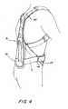
- Figure 1is a front perspective view of a posterior spinal orthosis on a user
- Figure 2is an elevated rear view of the spinal orthosis
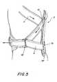
- Figure 3is a rear view of the orthosis on a user
- Figure 4is a side view of the orthosis on a user
- Figure 5is a partial side view of the side strapping configuration
- Figure 6is a perspective view of a user beginning the donning of the orthosis by closing the abdomen support members
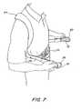
- Figure 7shows the user tightening the spinal orthosis by placing his fingers in pocketed finger pull tabs at the end of tightening straps
- Figure 8is a perspective view disclosing an adjustment of a tightening strap fitting on a user.
- Figure 9is a perspective view disclosing an adjustment of flexible strap members for adjustment to a user.
- a spinal orthosis 2has a posterior spinal member 8 with a frame member 74 either of a bent and curved metal plate or a molded plastic resin part.
- a flexible resilient pad 84is adhered on an internal surface of the spinal frame member 74 to provide a comfortable cushioned fit for the user.
- Elongated flexible strap members 4 and 6are removably attached at a top portion of an upper edge of a curved neck 78 of the spinal frame member 74.
- Upper attachment members 46 and 48 of appropriate looped straps 50 and 52are fastened by a screw or rivet as seen in Figure 2 adjacent the top of the curved neck 78.
- the respective straps 50 and 52anchor an upper attachment loop 54 and 56, respectively that can also support spinal adjustment straps 58 and 60.
- the elongated flexible strap members 4 and 6can be removably fastened to the respective loops 54 and 56.
- the strap members 4 and 6extend along the lateral sides of the spinal frame member 74.
- the curved neck 78extends down to an intermediate portion of the spinal frame member 74 and intermediate attachment members 10 and 12 are mounted on either side, in a width direction, of the spinal frame member 74.
- Looping attachment straps 14 and 16are appropriately fastened, for example, by rivets to the frame member 74 and capture attachment loops 18 and 20, respectively.
- the flexible strap members 4 and 6are journaled through the respective attachment loops 18 and 20 and are permanently fixed at a spinal triangular base 76 of the spinal frame member 74, for example by a rivet or other fastener, see Figures 2 and 4 .
- Each of the flexible strap members 4 and 6are configured to provide upper major loops that function as shoulder straps for a user or patient.
- Tubular shoulder pads 62 and 64are mounted on the respective strap members 4 and 6 within the upper major loops to cushion any force on the patient's shoulders.
- Minor lower loops of the strap members 4 and 6are further created between the riveted ends of the respective flexible strap members 4 and 6 and the attachment loops 18 and 20, respectively to enable securing the posterior spinal member triangular base 78 against the user's lower back as shown in Figure 4 .
- Flexible padded abdominal support members 22 and 24support connecting straps 26 and 28, respectively, that extend through respective double loops 42 and 44 on either side of the posterior spinal member 8.
- the abdominal support members 22 and 24can slide with the connecting straps 26 and 28 along the minor loops formed by the flexible strap members 4 and 6, see Figures 2 , 4 and 5 .
- the respective abdomen support members 22 and 24can be pulled and loosely fastened across an abdomen section of the user, as shown in Figure 7 .
- An abdomen support swatch of hook material 66for example of Velcro® can be located on an inner surface of each abdomen support member 22 and 24.
- the outside surface of each support member 22 and 24can have a nap fabric covering 68.
- fastening pads 30 and 32 with exterior pockets 34 and 36 respectively, of a size to receive one or more fingers,are attached at the other end of the respective connecting straps 26 and 28. Due to the size of the abdomen support members 22 and 24 and the fastening pads 30 and 32, the straps 26 and 28 are captured in one of the loops of the respective double loop members 42 and 44.
- the underside of each of the fastening pads 30 and 32have a fastening hook material 72 capable of engaging the napped or looped fabric of the reinforced straps 26 and 28 and an abdomen swatch of nap material 70 on an exterior surface of the abdomen support member 22.
- the length of the respective strap members 4 and 6can be appropriately adjusted by an orthotist, as seen in Figure 9 , by cutting the ends of the straps which have an exterior loop fabric texture and then capturing the cut end within the respective upper adjustment straps 58 and 60.
- the free end of the flexible strap member 4is cut to size for a particular patient and then secured in a sandwich like manner by the hook material provided on and between the upper adjustment straps 58.
- a similar size adjustment procedurecan be performed by an orthotist in cutting, for example, the connecting strap 26 at an end adjacent the fastening pad 30.
- the abdomen adjustment straps 38 and 40also have a hook material on their interior surfaces and adhere to the napped fabric on the exterior of the connecting straps 26 and 28, respectively, when secured in a sandwich manner over the ends of the adjustment straps.
- the present inventionpermits two areas of adjustment by cutting or removing unwanted lengths of the respective fastening strap members 4 and 6 and the respective connecting straps 26 and 28.
- the spinal frame member 74has a cross sectional curved neck portion 78 to provide rigidity and strength to the reduced width at the top of the spinal frame member 74 while also curved along a longitudinal axis to accommodate the curve of the spine.
- a series of holes 82can be provided for reducing weight.
- the lower triangular base 76also has an elongated central slot 80, also to reduce weight.
- the lower tip of base 76can be flared outward at the base of the spine.
- the resilient spinal pad 84has a napped fabric on one side specifically designed for adhering to a hook material, for example of a Velcro® brand.
- Swatches of Velcro® hook material 86can be appropriately adhered along an interior surface of the spinal frame 74 as shown in dotted lines in Figure 2 , as an illustration.
- the other side of the resilient spinal pad 84can have a pocked or apertured textured surface configuration to assist in aerating the length of the resilient spinal pad 84 that will bear against a user.
- the spinal pad 84is removable from the hook swatches 86 and washable for hygienic reasons.
- the spinal orthosis 2can then be easily donned by a user with limited mobility.
- the upper major loops formed by the flexible strap members 4 and 6will be encompassed with the shoulder tube pads 62 and 64.
- the usercan place their arms through these major loops so that the shoulder tube pads 62 and 64 are appropriately placed across the user's shoulders, as shown for example, in Figure 6 .
- the usercan then close the respective abdomen support members 22 and 24 so that the loop and hook material can adhere the abdomen support members 22 and 24 together while the straps 4 and 6 are still in a relatively loose condition.
- the usercan either grasp the fastening pads 30 and 32 and tighten the spinal orthosis against the spine as shown, for example, in Figure 5 , or can insert her/his fingers into the respective pockets 34 and 36 on the respective fastening pads 30 and 32 and by extending her/his arms, tighten the brace 2 to the spine of the user while pulling the flexible strap members 4 and 6.
- the tightened positionis then retained for wearing purposes.
- the spinal orthosiscan position a posterior spinal member 8 so that its length extends across the thoracic to the adjacent coccyx of the user's spine.
- the arrangement of the fastening straps 4 and 6provide not only an adjustable set of shoulder straps that can be easily donned by a user, but further contribute to the easy fastening of the flexible abdominal support members 24 and 22 together wherein extensions of the fastening pads 30 and 32 can removably secure the brace in position on the user's spine while specifically tightening the shoulder straps to draw the user's shoulders back against the posterior spinal member 8.
Landscapes
- Health & Medical Sciences (AREA)
- Nursing (AREA)
- Orthopedic Medicine & Surgery (AREA)
- Engineering & Computer Science (AREA)
- Biomedical Technology (AREA)
- Heart & Thoracic Surgery (AREA)
- Vascular Medicine (AREA)
- Life Sciences & Earth Sciences (AREA)
- Animal Behavior & Ethology (AREA)
- General Health & Medical Sciences (AREA)
- Public Health (AREA)
- Veterinary Medicine (AREA)
- Orthopedics, Nursing, And Contraception (AREA)
Description
- The present invention is directed to a lightweight spinal brace or othopraxis device for treatment of patients with upper back pain, strain, osteoporosis and compression fractures and more particularly, to an easily worn and adjustable extension compression posterior spinal orthosis for applying extension and compression forces in the treatment of spinal disorders.
- The prior art discloses various devices to provide an orthotic treatment to relieve pain and to provide compensation for various types of spinal disorders such as multiple compression fractures that may occur from osteoporosis and kythotic postural changes.
- Frequently, these spinal braces have employed a triangular or three point force vector system that includes an anchor point centrally located across the chest of the user which can be provided by a sternal pad supported, for example, by a metal frame and a corresponding anchor point on the lower portion of the abdomen, provided by a pubic pad supported by a frame. Thus, two forward pressure points are provided on the front of the user and a centrally located adjustable lumbar pad is provided on the user's back, again adjustably fixed to a metal frame so that three force vectors can be applied to create a condition of hyperextension on the spinal column, while permitting some mobility to the user. An example can be seen in the Jewett brace shown in
U.S. Patent No. 3,274,996 . - Basically, this orthotic modality of treatment involves an anterior spinal hyperextension orthosis to create spaced anterior anchor stabilization points across the sternum and pubic areas with an adjustable force applied at an intermediate position on the user's back. Numerous variations of this treatment can be found, for example in
U.S. Patent No. 5,599,287 ,U.S. Patent No. 6,190,343 ,U.S. Patent No. 6,790,191 ,U.S. Patent No. 6,010,472 ,U.S. Patent No. 5,674,187 , andU.S. Patent No. 3,945,376 . Other examples and variations can also be found in the orthodesic art. - An article in the American Journal of Physical Medicine and Rehabilitation "Effects of a New Spinal Orthosis of Posture, Trunk Strength And Quality of Life In Women With Postmenopausal Osteoporosis," Volume 83, No. 3, Pages 177-186, March 2004, described a study on the management of vertebra fractures caused by osteoporosis. A thoracolumbar orthosis disclosed in the study included a narrow back pad centered along the spine which could be workable as cold material to adjust to the particular patient, a system of belts, and an abdominal pad to apply lower, intermediate and upper forces on the back pad to mold it to the spinal region of the user. See
U.S. Patent No. 6,063,047 ,U.S. Patent No. 2,828,737 ,U.S. Patent No. 1,755,641 andU.S. Patent No. 1,581,791 . - There is still a need in the orthopedic field to provide an economical lightweight, comfortably wearing extension compression orthosis to treat mid spinal pathologies that does not require cumbersome strapping arrangements. Such a brace should be easily adjusted by the user to accommodate for various daily activity demands, to provide an improved, firm, lightweight posterior support structure that is easy to apply and that permits vector forces to be applied to the body by the user and to permit adjustments to match the size and configuration of the user.
- The International Patent Application Publication No.
WO 2007/043079 A1 discloses an orthopedic support or dorsal orthesis which can be used to support and block the spinal column of subjects with articular back problems or suffering from osteoporosis. That orthopedic support or dorsal orthesis comprises technical features which are described in the preamble of independent claim 1.
The International Patent Application Publication No.WO 99/65428 A1 - The present invention provides a spinal orthosis which is characterized by the technical features described in the characterizing portion of independent claim 1. Preferred embodiments of the present invention are described in the dependent claims.
- The present invention provides a lightweight spinal orthosis that can be adjustably mounted, for example by an orthotist in an economical manner so that it can be easily placed on a user's body to apply extension and compression forces in the treatment of spinal disorders. As can be appreciated, various medical issues and spinal problems can occur frequently with aging. The present orthosis can be economically manufactured and easily placed on and removed from the user or patient, preferably similar to putting on a clothing jacket. A rigid posterior frame or spinal member can be formed from a stamped metal plate or from a molded plastic and can be further subjectively configured to meet the demands and requirements of the specific patient.
- A pair of flexible strap members, attached adjacent an upper portion of the posterior spinal member, and attached adjacent a lower portion of the spinal member are provided on opposite lateral sides of the spinal member, and have a sufficient length to provide adjustable shoulder straps for the user. Thus, the shoulder straps can be conveniently adjusted to permit the user's arms to extend through the shoulder straps and then abdomen or waist closure pads are fastened together across the abdominal area of the patient and subsequently tighten to draw the flexible strap members against the patient's body.
- The waist closure pads can comprise a pair of flexible abdomen support members, having for example, a connecting strap attached to respective smaller loops of the flexible strap members located below the loops for accommodating shoulder straps. The flexible abdomen support members can adhere together and connecting straps with pocketed finger tabs can be adjustably fastened across the surface of the flexible abdomen support members and each other to secure the spinal member on the user while pulling the flexible strap members.
- The pair of flexible strap members can be removably attached adjacent an upper portion of the spinal member and permanently attached to a lower portion of the spinal member and adjustments can be easily made by an orthotist to both the flexible strap members and the connecting straps in order to size the spinal orthosis to a user.
- The posterior spinal member is approximately of a length to extend across the user's thoracic to the coccyx of the user's spine. The posterior spinal member can have an elongated triangular configuration with apertures to reduce weight. The spinal member can be formed from a thin metal plate and bent to increase strength while configured to the user's spine. Alternatively, the spinal member can be molded from a plastic resin.
- A replaceable resilient pad of a nap material on one side and an apertured texture to permit air flow can be removably attached to an internal surface of the posterior spine member for contacting the user's back.
- The objects and features of the present invention, which are believed to be novel, are set forth with particularity in the appended claims. The present invention, both as to its organization and manner of operation, together with further objects and advantages, may best be understood by reference to the following description, taken in connection with the accompanying drawings.
Figure 1 is a front perspective view of a posterior spinal orthosis on a user;Figure 2 is an elevated rear view of the spinal orthosis;Figure 3 is a rear view of the orthosis on a user;Figure 4 is a side view of the orthosis on a user;Figure 5 is a partial side view of the side strapping configuration;Figure 6 is a perspective view of a user beginning the donning of the orthosis by closing the abdomen support members;Figure 7 shows the user tightening the spinal orthosis by placing his fingers in pocketed finger pull tabs at the end of tightening straps;Figure 8 is a perspective view disclosing an adjustment of a tightening strap fitting on a user; andFigure 9 is a perspective view disclosing an adjustment of flexible strap members for adjustment to a user.- Reference will now be made in detail to the preferred embodiments of the invention which set forth the best modes contemplated to carry out the invention, examples of which are illustrated in the accompanying drawings. While the invention will be described in conjunction with the preferred embodiments, it will be understood that they are not intended to limit the invention to these embodiments.
- Referring to
Figures 1 and2 aspinal orthosis 2 has a posteriorspinal member 8 with aframe member 74 either of a bent and curved metal plate or a molded plastic resin part. - A flexible
resilient pad 84 is adhered on an internal surface of thespinal frame member 74 to provide a comfortable cushioned fit for the user. Elongatedflexible strap members curved neck 78 of thespinal frame member 74.Upper attachment members Figure 2 adjacent the top of thecurved neck 78. The respective straps 50 and 52 anchor anupper attachment loop - The elongated
flexible strap members respective loops strap members spinal frame member 74. Thecurved neck 78 extends down to an intermediate portion of thespinal frame member 74 andintermediate attachment members spinal frame member 74. Looping attachment straps 14 and 16 are appropriately fastened, for example, by rivets to theframe member 74 andcapture attachment loops - The
flexible strap members respective attachment loops triangular base 76 of thespinal frame member 74, for example by a rivet or other fastener, seeFigures 2 and4 . - Each of the
flexible strap members Tubular shoulder pads respective strap members strap members flexible strap members attachment loops triangular base 78 against the user's lower back as shown inFigure 4 . - Flexible padded
abdominal support members support connecting straps double loops spinal member 8. Thus, theabdominal support members straps flexible strap members Figures 2 ,4 and5 . - As can be seen in
Figure 6 , the respectiveabdomen support members Figure 7 . An abdomen support swatch ofhook material 66, for example of Velcro® can be located on an inner surface of eachabdomen support member support member abdomen support members - Additionally, as seen in
Figure 7 ,fastening pads exterior pockets straps abdomen support members fastening pads straps double loop members fastening pads fastening hook material 72 capable of engaging the napped or looped fabric of the reinforced straps 26 and 28 and an abdomen swatch ofnap material 70 on an exterior surface of theabdomen support member 22. - Thus, as seen in
Figure 7 , pulling therespective fastening pads waist connecting straps flexible strap members Figure 5 , will also tighten the shoulder straps offlexible strap members spinal member 8. Thefastening pads abdomen support members - As can be appreciated, the length of the
respective strap members Figure 9 , by cutting the ends of the straps which have an exterior loop fabric texture and then capturing the cut end within the respective upper adjustment straps 58 and 60. Thus, as is shown inFigure 9 , the free end of theflexible strap member 4 is cut to size for a particular patient and then secured in a sandwich like manner by the hook material provided on and between the upper adjustment straps 58. - As can be seen in
Figure 8 , a similar size adjustment procedure can be performed by an orthotist in cutting, for example, the connectingstrap 26 at an end adjacent thefastening pad 30. The abdomen adjustment straps 38 and 40 also have a hook material on their interior surfaces and adhere to the napped fabric on the exterior of the connectingstraps fastening strap members straps - The
spinal frame member 74 has a cross sectionalcurved neck portion 78 to provide rigidity and strength to the reduced width at the top of thespinal frame member 74 while also curved along a longitudinal axis to accommodate the curve of the spine. A series ofholes 82 can be provided for reducing weight. The lowertriangular base 76 also has an elongatedcentral slot 80, also to reduce weight. The lower tip ofbase 76 can be flared outward at the base of the spine. The resilientspinal pad 84 has a napped fabric on one side specifically designed for adhering to a hook material, for example of a Velcro® brand. Swatches of Velcro® hook material 86 can be appropriately adhered along an interior surface of thespinal frame 74 as shown in dotted lines inFigure 2 , as an illustration. The other side of the resilientspinal pad 84 can have a pocked or apertured textured surface configuration to assist in aerating the length of the resilientspinal pad 84 that will bear against a user. Thespinal pad 84 is removable from the hook swatches 86 and washable for hygienic reasons. - After an orthotist has appropriately sized the length of the pair of
flexible strap members straps Figures 8 and 9 , thespinal orthosis 2 can then be easily donned by a user with limited mobility. The upper major loops formed by theflexible strap members shoulder tube pads shoulder tube pads Figure 6 . The user can then close the respectiveabdomen support members abdomen support members straps - As shown in
Figure 7 , the user can either grasp thefastening pads Figure 5 , or can insert her/his fingers into therespective pockets respective fastening pads brace 2 to the spine of the user while pulling theflexible strap members fastening pads - In summary, the spinal orthosis can position a posterior
spinal member 8 so that its length extends across the thoracic to the adjacent coccyx of the user's spine. The arrangement of the fastening straps 4 and 6 provide not only an adjustable set of shoulder straps that can be easily donned by a user, but further contribute to the easy fastening of the flexibleabdominal support members fastening pads spinal member 8.
Claims (13)
- A spinal orthosis that is configured to be adjustably mounted to enable a user to apply extension and compression forces when tightening the spinal orthosis onto the user while being easily released to permit freedom of movement by the user, comprising:a posterior spinal member (8) configured to support a user's spine; anda pair of elongated flexible strap members (4, 6), each fastened at one end of the respective strap member (4, 6) on an upper portion of the posterior spinal member (8) and each fastened at the other end of the respective strap member (4, 6) on a lower portion of the posterior spinal member (8), the respective strap members (4, 6) extending on opposite sides of the posterior spinal member (8) and having a sufficient length to provide shoulder straps for the user;the spinal orthosis beingcharacterized by:a pair of attachment members (14, 16, 18, 20, 42, 44) located on the posterior spinal member (8) configured to enable a sliding movement for each flexible strap member (4, 6) through a corresponding attachment member (14, 16, 18, 20, 42, 44) to tighten the posterior spinal member (8) about the user's spine, one of each attachment member (14, 16, 18, 20, 42, 44) is located along a respective opposite side of the posterior spinal member (8) for enabling a respective flexible strap member (4, 6) to form an upper shoulder strap loop adjacent the upper portion of the posterior spinal member (8) and for providing a smaller loop than the shoulder strap loop adjacent the lower portion of the posterior spinal member (8); anda pair of flexible abdomen support members (22, 24), each having a connecting strap (26, 28) attached to an abdomen support member (22, 24) at one end of the connecting strap (26, 28) and slidably connected to a respective smaller loop of the flexible strap member(4, 6), wherein the flexible abdomen support members (22, 24) are configured to adhere together by the user to initially secure the spinal orthosis on the user and the other end of each of the connecting straps (26, 28) is configured to be pulled by the user to tighten the shoulder strap loop and the smaller loop, by applying extension and compression forces on the user, and to be fastened, relative to the spinal orthosis, to complete securement of the spinal orthosis on the user.
- The spinal orthosis of claim 1, wherein the flexible abdomen support members (22, 24) adhere together when overlapped.
- The spinal orthosis of claim 2, wherein the flexible abdomen support members (22, 24) have one of a nap material and a hook material on a surface for adhering together.
- The spinal orthosis of claim 1, wherein each connecting strap (26, 28) has a fastening pad (30, 32) at one end and an abdomen support member (22, 24) at the other end.
- The spinal orthosis of claim 4, wherein the fastening pad (30, 32) secures to a surface of one of the flexible abdomen support members (22, 24).
- The spinal orthosis of claim 5, wherein the flexible abdomen support member (22, 24) has an outer surface with a complementary surface (70, 72) for securement to a fastening pad (30, 32).
- The spinal orthosis of claim 4, wherein the fastening pad (30, 32) includes a pocket (34, 36) to permit a user's finger and/or fingers to be captured for tightening the connecting strap (26, 28).
- The spinal orthosis of claim 7, wherein the fastening pad (30, 32) includes a pair of flexible straps (38, 40) that removably adhere to one end of the connecting strap (26, 28).
- The spinal orthosis of claim 1, wherein a loop fastener (42, 44) connects the connecting strap (26, 28) for sliding movement on the smaller loop of the flexible strap member (4, 6).
- The spinal orthosis of claim 1, wherein the posterior spinal member (8) is a curved flat metal plate having a triangular base (76) and a narrower curved upper portion (78).
- The spinal orthosis of claim 10, wherein the posterior spinal member (8) includes strips of hook material (86) and a resilient pad (84) is removably connected to the hook material (86).
- The spinal orthosis of claim 11, wherein one surface of the resilient pad (84) has a nap material and the opposite surface has an apertured texture to permit air flow.
- The spinal orthosis of claim 1, wherein the pair of flexible strap members (4, 6) are attached to respectively cantilevered loops (54, 56) at the top of the posterior spinal member (8) and the flexible strap members (4, 6) have a removable strap (58, 60) that secures to both sides of each end of the strap members (4, 6) to enable adjustment and fit of a length of the strap members (4, 6) to the size of the user with the removable strap (58, 60) captured in the cantilevered loop (54, 56).
Applications Claiming Priority (2)
| Application Number | Priority Date | Filing Date | Title |
|---|---|---|---|
| US99930807P | 2007-10-17 | 2007-10-17 | |
| PCT/US2008/079592WO2009052031A1 (en) | 2007-10-17 | 2008-10-10 | Adjustable posterior spinal orthosis |
Publications (3)
| Publication Number | Publication Date |
|---|---|
| EP2200545A1 EP2200545A1 (en) | 2010-06-30 |
| EP2200545A4 EP2200545A4 (en) | 2012-02-29 |
| EP2200545B1true EP2200545B1 (en) | 2013-09-18 |
Family
ID=40567741
Family Applications (1)
| Application Number | Title | Priority Date | Filing Date |
|---|---|---|---|
| EP08840541.0ANot-in-forceEP2200545B1 (en) | 2007-10-17 | 2008-10-10 | Adjustable posterior spinal orthosis |
Country Status (3)
| Country | Link |
|---|---|
| US (1) | US20100318010A1 (en) |
| EP (1) | EP2200545B1 (en) |
| WO (1) | WO2009052031A1 (en) |
Cited By (2)
| Publication number | Priority date | Publication date | Assignee | Title |
|---|---|---|---|---|
| DE102020132128A1 (en) | 2020-12-03 | 2022-06-09 | Bort Gmbh | Back orthosis and kit for a back orthosis |
| DE102017108839B4 (en) | 2017-04-25 | 2022-07-14 | Ferd. Hauber Gmbh | back orthosis |
Families Citing this family (67)
| Publication number | Priority date | Publication date | Assignee | Title |
|---|---|---|---|---|
| US8585623B2 (en) | 2004-12-22 | 2013-11-19 | Ossur Hf | Orthopedic device |
| US8303527B2 (en) | 2007-06-20 | 2012-11-06 | Exos Corporation | Orthopedic system for immobilizing and supporting body parts |
| CN102421394B (en) | 2009-02-24 | 2015-04-01 | 伊克索斯有限责任公司 | Composites for Custom Fit Products |
| CN102333502B (en) | 2009-02-26 | 2014-06-25 | 欧苏尔公司 | Orthopedic devices used to treat the back |
| US8657769B2 (en)* | 2009-11-04 | 2014-02-25 | Ossur Hf | Thoracic lumbar sacral orthosis |
| US8556840B2 (en) | 2009-12-22 | 2013-10-15 | Aspen Medical Partners, Llc | Hyperextension brace |
| DE202010006538U1 (en) | 2010-05-07 | 2010-09-02 | Thuasne Deutschland Gmbh | spinal orthotic |
| US8783537B2 (en)* | 2010-07-28 | 2014-07-22 | Romina Ghassemi | Ergonomic backpack |
| AU2010358710A1 (en) | 2010-08-03 | 2013-03-21 | Von Zieglauer, Elizabeth | Orthopaedic device |
| US20120078149A1 (en)* | 2010-09-23 | 2012-03-29 | Mahnaz Azimzadeh | Orthopedic Posture Brace |
| ITMI20110461A1 (en)* | 2011-03-24 | 2012-09-25 | Orthoservice Ag | ADJUSTABLE ORTHOPEDIC CORSET FOR THE SUPPORT OF THE VERTEBRAL COLUMN |
| WO2012177700A2 (en) | 2011-06-20 | 2012-12-27 | Ossur Hf | Orthopedic device, use of orthopedic device and method for producing the same |
| US9931233B2 (en) | 2012-01-09 | 2018-04-03 | Breg, Inc. | Soft orthopedic knee brace for treatment of osteoarthritis |
| US9572705B2 (en) | 2012-01-13 | 2017-02-21 | Ossur Hf | Spinal orthosis |
| WO2013106666A1 (en) | 2012-01-13 | 2013-07-18 | Ossur Hf | Spinal orthosis and method for using the same |
| US10070985B2 (en)* | 2012-02-14 | 2018-09-11 | The Methodist Hospital System | Cervical spine orthosis |
| DE102012009250B4 (en)* | 2012-04-27 | 2016-05-25 | Bauerfeind Ag | Flexible closure element, closure consisting of two closure elements and use of at least one closure element |
| US9295748B2 (en) | 2012-07-31 | 2016-03-29 | Exos Llc | Foam core sandwich splint |
| US9408738B2 (en) | 2012-08-01 | 2016-08-09 | Exos Llc | Orthopedic brace for animals |
| US9615956B2 (en)* | 2012-08-02 | 2017-04-11 | Jack T. Sears | Orthopedic clavicle brace |
| US20140074003A1 (en)* | 2012-09-13 | 2014-03-13 | Nancy Monden | Posture and Lifting Orthotic |
| US12097139B2 (en) | 2012-09-13 | 2024-09-24 | Nancy Monden | Posture and lifting orthotic |
| EP2897559B1 (en) | 2012-09-19 | 2019-03-06 | Ossur HF | Panel attachment and circumference adjustment systems for an orthopedic device |
| US9655761B2 (en)* | 2012-11-12 | 2017-05-23 | Djo, Llc | Orthopedic back brace |
| CN105228564B (en) | 2013-01-07 | 2017-11-14 | 奥索有限责任公司 | Orthopedic device and fixation method thereof |
| WO2014116895A1 (en) | 2013-01-24 | 2014-07-31 | Ossur Hf | Orthopedic device for treating complications of the hip |
| US9554935B2 (en) | 2013-01-24 | 2017-01-31 | Ossur Hf | Orthopedic device for treating complications of the hip |
| US10357391B2 (en) | 2013-01-24 | 2019-07-23 | Ossur Hf | Orthopedic device for treating complications of the hip |
| US9795500B2 (en) | 2013-01-24 | 2017-10-24 | Ossur Hf | Orthopedic device for treating complications of the hip |
| EP2950758B1 (en) | 2013-01-31 | 2020-11-18 | Össur HF | Progressive force strap assembly for use with an orthopedic device |
| US9375341B2 (en) | 2013-01-31 | 2016-06-28 | Ossur Hf | Orthopedic device having detachable components for treatment stages and method for using the same |
| EP2983627B1 (en) | 2013-04-08 | 2018-12-12 | Ossur hf | Strap attachment system for orthopedic device |
| EP2865359A1 (en)* | 2013-10-22 | 2015-04-29 | Paul Chen | Back posture straightening device |
| USD878610S1 (en)* | 2014-08-26 | 2020-03-17 | Elliot Boston | Therapeutic heart pad |
| TWM500563U (en)* | 2014-10-22 | 2015-05-11 | Zentan Technology Co Ltd | Sternal support strap |
| WO2016112110A1 (en) | 2015-01-06 | 2016-07-14 | Ossur Iceland Ehf | Orthopedic device for treating osteoarthritis of the knee |
| US10561520B2 (en) | 2015-02-27 | 2020-02-18 | Ossur Iceland Ehf | Spinal orthosis, kit and method for using the same |
| WO2016138215A1 (en) | 2015-02-27 | 2016-09-01 | Ossur Iceland Ehf | Spinal orthosis, kit and method for using the same |
| USD776287S1 (en)* | 2015-05-29 | 2017-01-10 | Telebrands Corp. | Posture support device |
| DE102016201270A1 (en) | 2016-01-28 | 2017-08-03 | Bauerfeind Ag | Tension Strap-recliner |
| US11850175B2 (en) | 2016-06-06 | 2023-12-26 | Ossur Iceland Ehf | Orthopedic device, strap system and method for securing the same |
| US11253384B2 (en) | 2016-06-06 | 2022-02-22 | Ossur Iceland Ehf | Orthopedic device, strap system and method for securing the same |
| JP6273323B2 (en)* | 2016-07-20 | 2018-01-31 | ユーピーアール株式会社 | Assist suit |
| IT201600108678A1 (en)* | 2016-10-27 | 2018-04-27 | Dual Sanitaly S P A | GARMENT INCLUDING A T-SHIRT AND A SYSTEM TO CORRECT THE POSTURE OF A USER |
| USD911532S1 (en)* | 2017-04-21 | 2021-02-23 | OHEMAN International Mother and Baby Products (Shenzhen) Co., Ltd | Maternity belt |
| MX2019012562A (en) | 2017-04-25 | 2019-12-02 | Ossur Iceland Ehf | Interface system in an exoskeleton. |
| USD818132S1 (en)* | 2017-04-25 | 2018-05-15 | Amadeo Peter Hille | Posture correction device |
| USD844288S1 (en)* | 2017-05-15 | 2019-04-02 | Christopher Mark Cluett | Support garment |
| EP3678613B1 (en) | 2017-09-07 | 2023-08-09 | Össur Iceland EHF | Thoracic lumbar sacral orthosis attachment |
| US11000439B2 (en) | 2017-09-28 | 2021-05-11 | Ossur Iceland Ehf | Body interface |
| CN111278390B (en) | 2017-10-06 | 2022-12-20 | 奥索冰岛有限公司 | Orthopedic device for knee unloading |
| CA3089751A1 (en)* | 2018-01-29 | 2019-08-01 | Jim Mylonas | Postural orthosis support apparatus for personal body armor carriers |
| DE102018211431A1 (en)* | 2018-07-10 | 2020-01-16 | Bauerfeind Ag | Back support |
| USD882803S1 (en) | 2018-10-08 | 2020-04-28 | Ossur Iceland Ehf | Orthopedic shell |
| USD908458S1 (en) | 2018-10-08 | 2021-01-26 | Ossur Iceland Ehf | Hinge cover |
| USD888258S1 (en) | 2018-10-08 | 2020-06-23 | Ossur Iceland Ehf | Connector assembly |
| USD882804S1 (en)* | 2018-11-14 | 2020-04-28 | Nancy Matsuura | Posture brace with thermal pocket |
| DE102018009316A1 (en) | 2018-11-27 | 2020-05-28 | Bort Gmbh | Back brace for stabilizing a patient's back and method of applying the back brace |
| US11234853B2 (en)* | 2019-02-26 | 2022-02-01 | Orthocare Medical Equipment, Llc | Thoracic lumbar sacral orthosis back brace |
| US11324622B1 (en) | 2019-08-08 | 2022-05-10 | Preferred Prescription, Inc. | Back brace belt and apparatus, and method of belt length adjustment therefor |
| USD895128S1 (en)* | 2019-08-29 | 2020-09-01 | Hempvana, Llc | Posture support device |
| US11872150B2 (en) | 2020-12-28 | 2024-01-16 | Ossur Iceland Ehf | Sleeve and method for use with orthopedic device |
| LV15805B (en) | 2022-07-18 | 2024-04-20 | Agm Orthopaedics, Sia | ADJUSTABLE THERAPEUTIC APPARATUS FOR THE HUMAN TORSO |
| US20240324757A1 (en)* | 2023-03-30 | 2024-10-03 | Amelia Kevan | Apparatus for stabilizing the core of a person |
| USD1057965S1 (en)* | 2024-07-29 | 2025-01-14 | Dongguan Xiang'an Sports Goods Co., Ltd. | Posture corrector |
| USD1067439S1 (en)* | 2024-08-29 | 2025-03-18 | Hexing Huang | Posture support device |
| USD1086475S1 (en)* | 2025-04-16 | 2025-07-29 | Shenzhen Hongxingtu Technology Co., Ltd. | Lumbar support |
Family Cites Families (28)
| Publication number | Priority date | Publication date | Assignee | Title |
|---|---|---|---|---|
| US1316915A (en)* | 1919-09-23 | steinert | ||
| US1581791A (en)* | 1925-02-05 | 1926-04-20 | Elwin T Davison | Body and shoulder brace |
| US1755641A (en)* | 1928-06-08 | 1930-04-22 | Winifred De Puy Leiter | Surgical splint |
| US2687129A (en)* | 1952-01-11 | 1954-08-24 | Ernest E Talkish | Scoliosis brace |
| US2828737A (en) | 1953-04-02 | 1958-04-01 | Randall H Hale | Orthopraxis appliance for the back |
| US2808050A (en)* | 1954-07-27 | 1957-10-01 | Thomas C Ward | Surgical brace |
| US3095875A (en)* | 1961-08-28 | 1963-07-02 | Florida Brace Corp | Surgical brace |
| US3274996A (en) | 1961-09-01 | 1966-09-27 | Florida Brace Corp | Surgical brace |
| US3351053A (en)* | 1962-11-13 | 1967-11-07 | Florida Brace Corp | Flexion back brace |
| US3771513A (en)* | 1971-12-08 | 1973-11-13 | T Velazquez | Spinal brace |
| US3945376A (en)* | 1974-12-12 | 1976-03-23 | Otto Bock Orthopedic Industry, Inc. | Orthopedic brace (orthesis) |
| USRE31564E (en)* | 1978-06-30 | 1984-04-24 | Hyperextension back brace | |
| US4640269A (en)* | 1984-07-30 | 1987-02-03 | Joan Goins | Back brace having strap with widened middle portion for pad |
| US5241704A (en)* | 1991-04-23 | 1993-09-07 | Ergodyne Corporation | Back support |
| US5548843A (en)* | 1994-01-12 | 1996-08-27 | Chase Ergonomics Inc. | Back support with means to secure the belt on the wearer while in an open position |
| DE29504983U1 (en) | 1995-03-24 | 1995-05-18 | Otto Bock Orthopädische Industrie Besitz- und Verwaltungs-Kommanditgesellschaft, 37115 Duderstadt | Hyperextension orthosis |
| DE29506989U1 (en) | 1995-04-21 | 1996-08-22 | Weihermüller & Voigtmann GmbH & Co KG, 95448 Bayreuth | Hyperextension orthosis in frame construction |
| US5599287A (en) | 1995-10-03 | 1997-02-04 | Peach U.S., Inc. | Hyperextension orthotic apparatus useful for treating pain associated with spinal disorders |
| DE29720475U1 (en) | 1997-11-19 | 1998-02-19 | medi Bayreuth Weihermüller und Voigtmann GmbH & Co. KG, 95448 Bayreuth | Minimal orthosis for the treatment of osteoporosis |
| JP3328927B2 (en)* | 1998-05-11 | 2002-09-30 | 船井電機株式会社 | Drive control method of stepping motor |
| EP1087734A4 (en)* | 1998-06-18 | 2002-10-23 | Bio Cybernetics Internat | Custom fitted orthotic device |
| US6132393A (en)* | 1998-11-05 | 2000-10-17 | Lundberg; Leslie C. | Limited mobility shoulder brace |
| US6790191B1 (en) | 1999-11-10 | 2004-09-14 | David J. Hendricks | Hyperextension back brace system |
| US6190343B1 (en) | 1999-12-10 | 2001-02-20 | Bio Cybernetics International | Cruciform anterior spinal hyperextension orthosis |
| US7150048B2 (en)* | 2002-12-18 | 2006-12-19 | Buckman Robert F | Method and apparatus for body impact protection |
| ITVR20050125A1 (en) | 2005-10-12 | 2007-04-13 | Fgp Srl | ORTHOPEDIC SUPPORT OR DORSAL ORTHOSES FOR VERTEBRAL COLUMN |
| WO2007079387A2 (en)* | 2005-12-30 | 2007-07-12 | Rmk Accessories, Inc. | Modular pack system |
| DE102006043846A1 (en)* | 2006-03-14 | 2007-09-20 | Claudia Zours | Spinal |
- 2008
- 2008-10-10WOPCT/US2008/079592patent/WO2009052031A1/enactiveApplication Filing
- 2008-10-10EPEP08840541.0Apatent/EP2200545B1/ennot_activeNot-in-force
- 2008-10-10USUS12/738,276patent/US20100318010A1/ennot_activeAbandoned
Cited By (2)
| Publication number | Priority date | Publication date | Assignee | Title |
|---|---|---|---|---|
| DE102017108839B4 (en) | 2017-04-25 | 2022-07-14 | Ferd. Hauber Gmbh | back orthosis |
| DE102020132128A1 (en) | 2020-12-03 | 2022-06-09 | Bort Gmbh | Back orthosis and kit for a back orthosis |
Also Published As
| Publication number | Publication date |
|---|---|
| WO2009052031A1 (en) | 2009-04-23 |
| US20100318010A1 (en) | 2010-12-16 |
| EP2200545A4 (en) | 2012-02-29 |
| EP2200545A1 (en) | 2010-06-30 |
Similar Documents
| Publication | Publication Date | Title |
|---|---|---|
| EP2200545B1 (en) | Adjustable posterior spinal orthosis | |
| US8308670B2 (en) | Adjustable extension compression posterior spinal orthosis and method | |
| US6213968B1 (en) | Custom fitted orthotic device | |
| US5599287A (en) | Hyperextension orthotic apparatus useful for treating pain associated with spinal disorders | |
| US5853378A (en) | Lumbo-Sacral orthosis | |
| US9370440B2 (en) | Spinal orthosis | |
| US5634891A (en) | Orthotic apparatus useful for treating pain associated with spinal disorders | |
| US5722940A (en) | Industrial back support | |
| US20140058307A1 (en) | Adjustable back brace | |
| US7837639B2 (en) | Adjustable brace for correcting a forward lean | |
| US20150148727A1 (en) | Low-profile, postural corrective garment for therapeutic relief of low back pain and mechanical lumbar disorders | |
| US6110133A (en) | Convertible acromioclavicular stabilizer | |
| US4930499A (en) | Sacral brace | |
| US9615956B2 (en) | Orthopedic clavicle brace | |
| US20100262056A1 (en) | Back brace | |
| JP2013215246A (en) | Orthopedic appliance for spinal deformity | |
| EP4199868B1 (en) | Sacroiliac orthosis | |
| US20190038450A1 (en) | Shoulder compression harness | |
| US20120289874A1 (en) | Spinal Posture Brace | |
| JP6949308B2 (en) | Orthodontic tightening waist belt and its tightening method | |
| KR102683049B1 (en) | Orthosis for thoracic vertebra and vertebrae lumbales | |
| KR20190089927A (en) | Support band |
Legal Events
| Date | Code | Title | Description |
|---|---|---|---|
| PUAI | Public reference made under article 153(3) epc to a published international application that has entered the european phase | Free format text:ORIGINAL CODE: 0009012 | |
| 17P | Request for examination filed | Effective date:20100419 | |
| AK | Designated contracting states | Kind code of ref document:A1 Designated state(s):AT BE BG CH CY CZ DE DK EE ES FI FR GB GR HR HU IE IS IT LI LT LU LV MC MT NL NO PL PT RO SE SI SK TR | |
| AX | Request for extension of the european patent | Extension state:AL BA MK RS | |
| DAX | Request for extension of the european patent (deleted) | ||
| A4 | Supplementary search report drawn up and despatched | Effective date:20120130 | |
| RIC1 | Information provided on ipc code assigned before grant | Ipc:A61F 5/02 20060101AFI20120124BHEP | |
| 17Q | First examination report despatched | Effective date:20120913 | |
| GRAP | Despatch of communication of intention to grant a patent | Free format text:ORIGINAL CODE: EPIDOSNIGR1 | |
| INTG | Intention to grant announced | Effective date:20130604 | |
| GRAS | Grant fee paid | Free format text:ORIGINAL CODE: EPIDOSNIGR3 | |
| GRAA | (expected) grant | Free format text:ORIGINAL CODE: 0009210 | |
| AK | Designated contracting states | Kind code of ref document:B1 Designated state(s):AT BE BG CH CY CZ DE DK EE ES FI FR GB GR HR HU IE IS IT LI LT LU LV MC MT NL NO PL PT RO SE SI SK TR | |
| REG | Reference to a national code | Ref country code:GB Ref legal event code:FG4D | |
| REG | Reference to a national code | Ref country code:CH Ref legal event code:EP | |
| REG | Reference to a national code | Ref country code:IE Ref legal event code:FG4D | |
| REG | Reference to a national code | Ref country code:AT Ref legal event code:REF Ref document number:632328 Country of ref document:AT Kind code of ref document:T Effective date:20131015 | |
| REG | Reference to a national code | Ref country code:DE Ref legal event code:R096 Ref document number:602008027686 Country of ref document:DE Effective date:20131114 | |
| PG25 | Lapsed in a contracting state [announced via postgrant information from national office to epo] | Ref country code:NO Free format text:LAPSE BECAUSE OF FAILURE TO SUBMIT A TRANSLATION OF THE DESCRIPTION OR TO PAY THE FEE WITHIN THE PRESCRIBED TIME-LIMIT Effective date:20131218 Ref country code:CY Free format text:LAPSE BECAUSE OF FAILURE TO SUBMIT A TRANSLATION OF THE DESCRIPTION OR TO PAY THE FEE WITHIN THE PRESCRIBED TIME-LIMIT Effective date:20130828 Ref country code:HR Free format text:LAPSE BECAUSE OF FAILURE TO SUBMIT A TRANSLATION OF THE DESCRIPTION OR TO PAY THE FEE WITHIN THE PRESCRIBED TIME-LIMIT Effective date:20130918 Ref country code:LT Free format text:LAPSE BECAUSE OF FAILURE TO SUBMIT A TRANSLATION OF THE DESCRIPTION OR TO PAY THE FEE WITHIN THE PRESCRIBED TIME-LIMIT Effective date:20130918 Ref country code:SE Free format text:LAPSE BECAUSE OF FAILURE TO SUBMIT A TRANSLATION OF THE DESCRIPTION OR TO PAY THE FEE WITHIN THE PRESCRIBED TIME-LIMIT Effective date:20130918 | |
| REG | Reference to a national code | Ref country code:NL Ref legal event code:VDEP Effective date:20130918 | |
| REG | Reference to a national code | Ref country code:AT Ref legal event code:MK05 Ref document number:632328 Country of ref document:AT Kind code of ref document:T Effective date:20130918 | |
| REG | Reference to a national code | Ref country code:LT Ref legal event code:MG4D | |
| PG25 | Lapsed in a contracting state [announced via postgrant information from national office to epo] | Ref country code:LV Free format text:LAPSE BECAUSE OF FAILURE TO SUBMIT A TRANSLATION OF THE DESCRIPTION OR TO PAY THE FEE WITHIN THE PRESCRIBED TIME-LIMIT Effective date:20130918 Ref country code:FI Free format text:LAPSE BECAUSE OF FAILURE TO SUBMIT A TRANSLATION OF THE DESCRIPTION OR TO PAY THE FEE WITHIN THE PRESCRIBED TIME-LIMIT Effective date:20130918 Ref country code:SI Free format text:LAPSE BECAUSE OF FAILURE TO SUBMIT A TRANSLATION OF THE DESCRIPTION OR TO PAY THE FEE WITHIN THE PRESCRIBED TIME-LIMIT Effective date:20130918 Ref country code:GR Free format text:LAPSE BECAUSE OF FAILURE TO SUBMIT A TRANSLATION OF THE DESCRIPTION OR TO PAY THE FEE WITHIN THE PRESCRIBED TIME-LIMIT Effective date:20131219 | |
| PG25 | Lapsed in a contracting state [announced via postgrant information from national office to epo] | Ref country code:CY Free format text:LAPSE BECAUSE OF FAILURE TO SUBMIT A TRANSLATION OF THE DESCRIPTION OR TO PAY THE FEE WITHIN THE PRESCRIBED TIME-LIMIT Effective date:20130918 Ref country code:BE Free format text:LAPSE BECAUSE OF FAILURE TO SUBMIT A TRANSLATION OF THE DESCRIPTION OR TO PAY THE FEE WITHIN THE PRESCRIBED TIME-LIMIT Effective date:20130918 | |
| PG25 | Lapsed in a contracting state [announced via postgrant information from national office to epo] | Ref country code:CZ Free format text:LAPSE BECAUSE OF FAILURE TO SUBMIT A TRANSLATION OF THE DESCRIPTION OR TO PAY THE FEE WITHIN THE PRESCRIBED TIME-LIMIT Effective date:20130918 Ref country code:SK Free format text:LAPSE BECAUSE OF FAILURE TO SUBMIT A TRANSLATION OF THE DESCRIPTION OR TO PAY THE FEE WITHIN THE PRESCRIBED TIME-LIMIT Effective date:20130918 Ref country code:EE Free format text:LAPSE BECAUSE OF FAILURE TO SUBMIT A TRANSLATION OF THE DESCRIPTION OR TO PAY THE FEE WITHIN THE PRESCRIBED TIME-LIMIT Effective date:20130918 Ref country code:NL Free format text:LAPSE BECAUSE OF FAILURE TO SUBMIT A TRANSLATION OF THE DESCRIPTION OR TO PAY THE FEE WITHIN THE PRESCRIBED TIME-LIMIT Effective date:20130918 Ref country code:RO Free format text:LAPSE BECAUSE OF FAILURE TO SUBMIT A TRANSLATION OF THE DESCRIPTION OR TO PAY THE FEE WITHIN THE PRESCRIBED TIME-LIMIT Effective date:20130918 Ref country code:IS Free format text:LAPSE BECAUSE OF FAILURE TO SUBMIT A TRANSLATION OF THE DESCRIPTION OR TO PAY THE FEE WITHIN THE PRESCRIBED TIME-LIMIT Effective date:20140118 | |
| PG25 | Lapsed in a contracting state [announced via postgrant information from national office to epo] | Ref country code:PL Free format text:LAPSE BECAUSE OF FAILURE TO SUBMIT A TRANSLATION OF THE DESCRIPTION OR TO PAY THE FEE WITHIN THE PRESCRIBED TIME-LIMIT Effective date:20130918 Ref country code:AT Free format text:LAPSE BECAUSE OF FAILURE TO SUBMIT A TRANSLATION OF THE DESCRIPTION OR TO PAY THE FEE WITHIN THE PRESCRIBED TIME-LIMIT Effective date:20130918 Ref country code:ES Free format text:LAPSE BECAUSE OF FAILURE TO SUBMIT A TRANSLATION OF THE DESCRIPTION OR TO PAY THE FEE WITHIN THE PRESCRIBED TIME-LIMIT Effective date:20130918 | |
| REG | Reference to a national code | Ref country code:CH Ref legal event code:PL | |
| REG | Reference to a national code | Ref country code:DE Ref legal event code:R097 Ref document number:602008027686 Country of ref document:DE | |
| PG25 | Lapsed in a contracting state [announced via postgrant information from national office to epo] | Ref country code:MC Free format text:LAPSE BECAUSE OF FAILURE TO SUBMIT A TRANSLATION OF THE DESCRIPTION OR TO PAY THE FEE WITHIN THE PRESCRIBED TIME-LIMIT Effective date:20130918 Ref country code:PT Free format text:LAPSE BECAUSE OF FAILURE TO SUBMIT A TRANSLATION OF THE DESCRIPTION OR TO PAY THE FEE WITHIN THE PRESCRIBED TIME-LIMIT Effective date:20140120 | |
| PLBE | No opposition filed within time limit | Free format text:ORIGINAL CODE: 0009261 | |
| STAA | Information on the status of an ep patent application or granted ep patent | Free format text:STATUS: NO OPPOSITION FILED WITHIN TIME LIMIT | |
| REG | Reference to a national code | Ref country code:IE Ref legal event code:MM4A | |
| PG25 | Lapsed in a contracting state [announced via postgrant information from national office to epo] | Ref country code:LI Free format text:LAPSE BECAUSE OF NON-PAYMENT OF DUE FEES Effective date:20131031 Ref country code:CH Free format text:LAPSE BECAUSE OF NON-PAYMENT OF DUE FEES Effective date:20131031 | |
| REG | Reference to a national code | Ref country code:FR Ref legal event code:ST Effective date:20140630 | |
| 26N | No opposition filed | Effective date:20140619 | |
| GBPC | Gb: european patent ceased through non-payment of renewal fee | Effective date:20131218 | |
| PG25 | Lapsed in a contracting state [announced via postgrant information from national office to epo] | Ref country code:IT Free format text:LAPSE BECAUSE OF FAILURE TO SUBMIT A TRANSLATION OF THE DESCRIPTION OR TO PAY THE FEE WITHIN THE PRESCRIBED TIME-LIMIT Effective date:20130918 Ref country code:FR Free format text:LAPSE BECAUSE OF NON-PAYMENT OF DUE FEES Effective date:20131118 | |
| REG | Reference to a national code | Ref country code:DE Ref legal event code:R097 Ref document number:602008027686 Country of ref document:DE Effective date:20140619 | |
| PG25 | Lapsed in a contracting state [announced via postgrant information from national office to epo] | Ref country code:DK Free format text:LAPSE BECAUSE OF FAILURE TO SUBMIT A TRANSLATION OF THE DESCRIPTION OR TO PAY THE FEE WITHIN THE PRESCRIBED TIME-LIMIT Effective date:20130918 | |
| PG25 | Lapsed in a contracting state [announced via postgrant information from national office to epo] | Ref country code:IE Free format text:LAPSE BECAUSE OF NON-PAYMENT OF DUE FEES Effective date:20131010 | |
| PG25 | Lapsed in a contracting state [announced via postgrant information from national office to epo] | Ref country code:GB Free format text:LAPSE BECAUSE OF NON-PAYMENT OF DUE FEES Effective date:20131218 | |
| PG25 | Lapsed in a contracting state [announced via postgrant information from national office to epo] | Ref country code:TR Free format text:LAPSE BECAUSE OF FAILURE TO SUBMIT A TRANSLATION OF THE DESCRIPTION OR TO PAY THE FEE WITHIN THE PRESCRIBED TIME-LIMIT Effective date:20130918 | |
| PG25 | Lapsed in a contracting state [announced via postgrant information from national office to epo] | Ref country code:BG Free format text:LAPSE BECAUSE OF FAILURE TO SUBMIT A TRANSLATION OF THE DESCRIPTION OR TO PAY THE FEE WITHIN THE PRESCRIBED TIME-LIMIT Effective date:20130918 Ref country code:LU Free format text:LAPSE BECAUSE OF NON-PAYMENT OF DUE FEES Effective date:20131010 Ref country code:HU Free format text:LAPSE BECAUSE OF FAILURE TO SUBMIT A TRANSLATION OF THE DESCRIPTION OR TO PAY THE FEE WITHIN THE PRESCRIBED TIME-LIMIT; INVALID AB INITIO Effective date:20081010 | |
| PG25 | Lapsed in a contracting state [announced via postgrant information from national office to epo] | Ref country code:MT Free format text:LAPSE BECAUSE OF FAILURE TO SUBMIT A TRANSLATION OF THE DESCRIPTION OR TO PAY THE FEE WITHIN THE PRESCRIBED TIME-LIMIT Effective date:20130918 | |
| PGFP | Annual fee paid to national office [announced via postgrant information from national office to epo] | Ref country code:DE Payment date:20201028 Year of fee payment:13 | |
| REG | Reference to a national code | Ref country code:DE Ref legal event code:R119 Ref document number:602008027686 Country of ref document:DE | |
| PG25 | Lapsed in a contracting state [announced via postgrant information from national office to epo] | Ref country code:DE Free format text:LAPSE BECAUSE OF NON-PAYMENT OF DUE FEES Effective date:20220503 |