EP2200458B1 - Apparatus and method for microwave vacuum-drying of organic materials - Google Patents
Apparatus and method for microwave vacuum-drying of organic materialsDownload PDFInfo
- Publication number
- EP2200458B1 EP2200458B1EP08838608.1AEP08838608AEP2200458B1EP 2200458 B1EP2200458 B1EP 2200458B1EP 08838608 AEP08838608 AEP 08838608AEP 2200458 B1EP2200458 B1EP 2200458B1
- Authority
- EP
- European Patent Office
- Prior art keywords
- container
- chamber
- vacuum chamber
- organic material
- equilibration
- Prior art date
- Legal status (The legal status is an assumption and is not a legal conclusion. Google has not performed a legal analysis and makes no representation as to the accuracy of the status listed.)
- Active
Links
Images


Classifications
- A—HUMAN NECESSITIES
- A23—FOODS OR FOODSTUFFS; TREATMENT THEREOF, NOT COVERED BY OTHER CLASSES
- A23B—PRESERVATION OF FOODS, FOODSTUFFS OR NON-ALCOHOLIC BEVERAGES; CHEMICAL RIPENING OF FRUIT OR VEGETABLES
- A23B2/00—Preservation of foods or foodstuffs, in general
- A23B2/05—Preservation of foods or foodstuffs, in general by heating using irradiation or electric treatment
- A23B2/08—Preservation of foods or foodstuffs, in general by heating using irradiation or electric treatment using microwaves or dielectric heating
- A—HUMAN NECESSITIES
- A23—FOODS OR FOODSTUFFS; TREATMENT THEREOF, NOT COVERED BY OTHER CLASSES
- A23B—PRESERVATION OF FOODS, FOODSTUFFS OR NON-ALCOHOLIC BEVERAGES; CHEMICAL RIPENING OF FRUIT OR VEGETABLES
- A23B2/00—Preservation of foods or foodstuffs, in general
- A23B2/70—Preservation of foods or foodstuffs, in general by treatment with chemicals
- A23B2/704—Preservation of foods or foodstuffs, in general by treatment with chemicals in the form of gases, e.g. fumigation; Compositions or apparatus therefor
- A23B2/708—Preservation of foods or foodstuffs, in general by treatment with chemicals in the form of gases, e.g. fumigation; Compositions or apparatus therefor in a controlled atmosphere, e.g. partial vacuum, comprising only CO2, N2, O2 or H2O
- A—HUMAN NECESSITIES
- A23—FOODS OR FOODSTUFFS; TREATMENT THEREOF, NOT COVERED BY OTHER CLASSES
- A23B—PRESERVATION OF FOODS, FOODSTUFFS OR NON-ALCOHOLIC BEVERAGES; CHEMICAL RIPENING OF FRUIT OR VEGETABLES
- A23B2/00—Preservation of foods or foodstuffs, in general
- A23B2/90—Preservation of foods or foodstuffs, in general by drying or kilning; Subsequent reconstitution
- A23B2/97—Preservation of foods or foodstuffs, in general by drying or kilning; Subsequent reconstitution using irradiation or electric treatment, e.g. ultrasonic waves
- A—HUMAN NECESSITIES
- A23—FOODS OR FOODSTUFFS; TREATMENT THEREOF, NOT COVERED BY OTHER CLASSES
- A23B—PRESERVATION OF FOODS, FOODSTUFFS OR NON-ALCOHOLIC BEVERAGES; CHEMICAL RIPENING OF FRUIT OR VEGETABLES
- A23B7/00—Preservation of fruit or vegetables; Chemical ripening of fruit or vegetables
- A23B7/005—Preserving by heating
- A23B7/01—Preserving by heating by irradiation or electric treatment
- A—HUMAN NECESSITIES
- A23—FOODS OR FOODSTUFFS; TREATMENT THEREOF, NOT COVERED BY OTHER CLASSES
- A23B—PRESERVATION OF FOODS, FOODSTUFFS OR NON-ALCOHOLIC BEVERAGES; CHEMICAL RIPENING OF FRUIT OR VEGETABLES
- A23B7/00—Preservation of fruit or vegetables; Chemical ripening of fruit or vegetables
- A23B7/02—Dehydrating; Subsequent reconstitution
- A—HUMAN NECESSITIES
- A23—FOODS OR FOODSTUFFS; TREATMENT THEREOF, NOT COVERED BY OTHER CLASSES
- A23B—PRESERVATION OF FOODS, FOODSTUFFS OR NON-ALCOHOLIC BEVERAGES; CHEMICAL RIPENING OF FRUIT OR VEGETABLES
- A23B7/00—Preservation of fruit or vegetables; Chemical ripening of fruit or vegetables
- A23B7/14—Preserving or ripening with chemicals not covered by group A23B7/08 or A23B7/10
- A23B7/144—Preserving or ripening with chemicals not covered by group A23B7/08 or A23B7/10 in the form of gases, e.g. fumigation; Compositions or apparatus therefor
- A23B7/148—Preserving or ripening with chemicals not covered by group A23B7/08 or A23B7/10 in the form of gases, e.g. fumigation; Compositions or apparatus therefor in a controlled atmosphere, e.g. partial vacuum, comprising only CO2, N2, O2 or H2O
- F—MECHANICAL ENGINEERING; LIGHTING; HEATING; WEAPONS; BLASTING
- F26—DRYING
- F26B—DRYING SOLID MATERIALS OR OBJECTS BY REMOVING LIQUID THEREFROM
- F26B15/00—Machines or apparatus for drying objects with progressive movement; Machines or apparatus with progressive movement for drying batches of material in compact form
- F26B15/10—Machines or apparatus for drying objects with progressive movement; Machines or apparatus with progressive movement for drying batches of material in compact form with movement in a path composed of one or more straight lines, e.g. compound, the movement being in alternate horizontal and vertical directions
- F26B15/12—Machines or apparatus for drying objects with progressive movement; Machines or apparatus with progressive movement for drying batches of material in compact form with movement in a path composed of one or more straight lines, e.g. compound, the movement being in alternate horizontal and vertical directions the lines being all horizontal or slightly inclined
- F26B15/14—Machines or apparatus for drying objects with progressive movement; Machines or apparatus with progressive movement for drying batches of material in compact form with movement in a path composed of one or more straight lines, e.g. compound, the movement being in alternate horizontal and vertical directions the lines being all horizontal or slightly inclined the objects or batches of materials being carried by trays or racks or receptacles, which may be connected to endless chains or belts
- F26B15/143—Machines or apparatus for drying objects with progressive movement; Machines or apparatus with progressive movement for drying batches of material in compact form with movement in a path composed of one or more straight lines, e.g. compound, the movement being in alternate horizontal and vertical directions the lines being all horizontal or slightly inclined the objects or batches of materials being carried by trays or racks or receptacles, which may be connected to endless chains or belts the receptacles being wholly or partly foraminous, e.g. containing a batch of loose material
- F—MECHANICAL ENGINEERING; LIGHTING; HEATING; WEAPONS; BLASTING
- F26—DRYING
- F26B—DRYING SOLID MATERIALS OR OBJECTS BY REMOVING LIQUID THEREFROM
- F26B17/00—Machines or apparatus for drying materials in loose, plastic, or fluidised form, e.g. granules, staple fibres, with progressive movement
- F26B17/30—Machines or apparatus for drying materials in loose, plastic, or fluidised form, e.g. granules, staple fibres, with progressive movement with movement performed by rotary or oscillating containers; with movement performed by rotary floors
- F—MECHANICAL ENGINEERING; LIGHTING; HEATING; WEAPONS; BLASTING
- F26—DRYING
- F26B—DRYING SOLID MATERIALS OR OBJECTS BY REMOVING LIQUID THEREFROM
- F26B3/00—Drying solid materials or objects by processes involving the application of heat
- F26B3/32—Drying solid materials or objects by processes involving the application of heat by development of heat within the materials or objects to be dried, e.g. by fermentation or other microbiological action
- F26B3/34—Drying solid materials or objects by processes involving the application of heat by development of heat within the materials or objects to be dried, e.g. by fermentation or other microbiological action by using electrical effects
- F26B3/347—Electromagnetic heating, e.g. induction heating or heating using microwave energy
- F—MECHANICAL ENGINEERING; LIGHTING; HEATING; WEAPONS; BLASTING
- F26—DRYING
- F26B—DRYING SOLID MATERIALS OR OBJECTS BY REMOVING LIQUID THEREFROM
- F26B5/00—Drying solid materials or objects by processes not involving the application of heat
- F26B5/04—Drying solid materials or objects by processes not involving the application of heat by evaporation or sublimation of moisture under reduced pressure, e.g. in a vacuum
- F26B5/042—Drying solid materials or objects by processes not involving the application of heat by evaporation or sublimation of moisture under reduced pressure, e.g. in a vacuum for drying articles or discrete batches of material in a continuous or semi-continuous operation, e.g. with locks or other air tight arrangements for charging/discharging
Definitions
- the inventionpertains to apparatuses and methods for microwave vacuum-drying of organic materials, such as food products and medicinal plants.
- Dehydration of organic materialsis common in the food processing and the medicinal herb industry. It may be done in order to preserve the products for storage, for example fruits and vegetables, the dehydrated products being later rehydrated for consumption. Dehydration may also be done to create a product that is used in the dehydrated form, for example dried herbs and various kinds of chips.
- Conventional methods of dehydrating such materialsinclude air-drying and freeze-drying. Both of these drying methods have their limitations. In general terms, air- drying is slow and freeze-drying is expensive, and both methods tend to degrade the appearance and texture of the products.
- Microwave vacuum-dryingis a rapid method that can yield products with improved quality compared to air-dried and freeze-dried products.
- the dryingis done under reduced pressure, the boiling point of water and the oxygen content of the atmosphere is lowered, so food or medicinal components sensitive to oxidation and thermal degradation can be retained to a higher degree than by air-drying.
- the drying processis also much faster than air- and freeze-drying.
- the present inventionis directed to improvements in the art of microwave vacuum-drying.
- an apparatus for dehydrating organic materialhas an input end for the introduction of a container of the material to be dehydrated and a discharge end for removal of the container of dehydrated material.
- the apparatushas a microwave generator and a microwave-transparent window for transmission of microwave radiation from the generator into the vacuum chamber. It includes means for reducing pressure inside the vacuum chamber, means for loading the container of organic material into the input end, means for rotating the container inside the vacuum chamber, means for moving the rotating container from the input end to the discharge end, and means for unloading the container of dehydrated material from the vacuum chamber at the discharge end.
- the apparatusmay optionally include means for cooling the dehydrated organic material at a pressure less than atmospheric.
- an apparatus for dehydrating organic materialcomprising a vacuum chamber, a microwave generator and a microwave-transparent window for transmission of microwave radiation from the generator into the vacuum chamber, and means for blowing a stream of air or other gas into the vacuum chamber adjacent to the window.
- This aspect of the inventionis directed to reducing the arcing of microwave radiation that occurs in microwave vacuum-dehydrators. Such arcing can destroy the microwave-transparent windows of the vacuum chamber and cause burning of the products being dehydrated.
- the present inventorshave discovered that blowing a stream of gas adjacent to the inside of the microwave-transparent windows, inside the vacuum chamber, reduces arcing during operation of a microwave-vacuum apparatus. It is believed that this is due, first, to the creation of a pressure gradiant between the window and the interior of the vacuum chamber, and second, to the prevention of condensation of water and other volatile materials on the inside of the window.
- a method for dehydrating an organic materialA microwave-transparent container holding the organic material to be dehydrated is provided.
- the containeris introduced into a vacuum chamber, the chamber being at a pressure less than atmospheric.
- the containeris rotated inside the vacuum chamber and the rotating container is moved through the vacuum chamber while applying microwave radiation to dehydrate the organic materials.
- the container of dehydrated organic materialis then removed from the vacuum chamber.
- the methodmay optionally include the step, after removal of the dehydrated organic material from the vacuum chamber, of cooling the material at a pressure less than atmospheric.
- a method for dehydrating an organic materialA vacuum chamber is evacuated, i.e. brought to a pressure that is less than atmospheric. Microwave radiation is transmitted into the vacuum chamber through a microwave-transparent window. A stream of gas, for example air, nitrogen or helium, is blown into the vacuum chamber adjacent to the window. The organic material to be dehydrated is introduced into the vacuum chamber and allowed to be dehydrated. The dehydrated material is then removed from the vacuum chamber.
- Organic materials that may be dehydrated using the apparatuses and methods of the inventioninclude food products such as fruits, berries (e.g. blueberries, cranberries, strawberries), vegetables, chips (e.g. apple, potato, banana, tortilla), herbs, meats, nutraceuticals, seeds, flowers and other plant materials such as roots, tubers, stems, leaves, etc.
- food productssuch as fruits, berries (e.g. blueberries, cranberries, strawberries), vegetables, chips (e.g. apple, potato, banana, tortilla), herbs, meats, nutraceuticals, seeds, flowers and other plant materials such as roots, tubers, stems, leaves, etc.
- the dehydrating apparatus 20has a vacuum chamber 22 within which an organic material in a cylindrical container 38 is dehydrated, a microwave generator 56 , an equilibration chamber 150 for cooling the dehydrated material at reduced pressure, a loading module 36 to load containers into the vacuum chamber, a transfer module 42 to transfer containers from the vacuum chamber to the equilibration chamber, and an unloading module 154.
- Each of the loading module 36 , transfer module 42 and unloading module 154has a pair of airlocks, respectively 101 and 102 , 130 and 111 , and 164 and 170 . These permit the containers to be, respectively, loaded into the vacuum chamber, transferred from the vacuum chamber to the equilibration chamber, and unloaded from the equilibration chamber, while maintaining those chambers at the reduced pressures required for the dehydrating process.
- the structure of each of the airlocksis the same, comprising a self-sealing door movable within a housing by the piston of an air cylinder. Lifting the door opens it and allows a container to pass; lowering the door closes it and forms an airtight seal.
- the dehydrating apparatus 20has a vacuum chamber 22 supported by a stand 24.
- the chamber 22has a cylindrical wall 26 , an end cover 28 at the input end 30 of the chamber and an end cover 32 at the discharge end 34 of the chamber.
- the loading module 36is supported on a stand 37 and connected to the end cover 28 at the input end 30 for loading containers 38 containing organic materials 40 to be dehydrated into the vacuum chamber 22.
- the transfer module 42 supported on a stand 43is connected to the end cover 32 at the opposite, discharge end 34 of the vacuum chamber.
- the vacuum chamber 22is oriented with its longitudinal axis approximately horizontal.
- the stands 37 , 43are each supported on respective wheels 25 arranged on rails 27 , facilitating separation of the modules from the vacuum chamber and equilibration chamber for servicing of the apparatus.
- each window assemblyhas a rectangular frame 48 extending from the outside of the wall 26 with a flange 50 at the outer edge of the frame 48 .
- a microwave-transparent window 54is positioned in the flange.
- the window 54is secured in place by a spacer 52 and a microwave input horn 53 , which is attached to the window frame flange 50 by means of a flange 55 at the base of the input horn 53 .
- the input horns 53are operatively attached to a microwave generator 56 by waveguides (not shown).
- the microwave input horns 53are rectangular in cross-section at their upper end, the rectangles having a short side 57 and a long side 59.
- the long sides 59 of the microwave input horns 53 of the window assemblies 44 , 46are oriented parallel to the longitudinal axis of the vacuum chamber 22 .
- the inlet port 58is connected to a source of another gas, for example an inert gas such as nitrogen or helium.
- a rotatable cylindrical cage 64 inside the vacuum chamberis adapted to receive and rotate the containers 38 .
- the cylindrical cage 64is an open-sided structure.
- the cylindrical cage 64has a ring gear 66 , 68 at each respective longitudinal end, connected by a set of circumferentially-spaced longitudinal members 70 .
- Circumferential support rings 72are attached to the longitudinal members 70 at approximately one-quarter and three-quarters of the distance between the ring gears 66 , 68.
- the cylindrical cage 64is reinforced by steel frame rods 73 affixed to the longitudinal members 70 along their length and by steel frame rings 74 adjacent to the ring gears 66 , 68 and at the longitudinal midpoint of the cylindrical cage.
- the cylindrical cageaccommodates six containers 38 end to end.
- the cylindrical cage and vacuum chamberare shown in the drawings as holding four containers only.
- the cylindrical cage and vacuum chambercan be made in a size to hold any selected number of containers.
- a pair of gears at each end of the vacuum chambersupport the cylindrical cage.
- Two gears 76 , 78are mounted on the end cover 28 at the input end 30 of the vacuum chamber to engage the ring gear 66
- two gears(one of which is indicated by reference numeral 80 in Fig. 4 ) are mounted on the end cover 32 at the discharge end 34 to engage the other ring gear 68 .
- One gear 76 , 80 of each setis driven by a respective motor 84 , 86 , synchronized together, to rotate the cylindrical cage 64 about its longitudinal, horizontal axis, within the vacuum chamber.
- the loading module 36has a container input chamber 88 adjacent to the end cover 28 of the vacuum chamber with an opening 90 through the end cover 28 that is aligned with the open, receiving end 92 of the cylindrical cage 64 , such that a container 38 in the input chamber 88 may be pushed through the opening 90 into the cylindrical cage 64 .
- the loading module 36has a loading channel 94 for the introduction of containers into the input chamber 88 .
- the loading channel 94has an inner end 96 adjacent to the input chamber 88 and an outer end 98 .
- An airlock assembly 101is provided at the outer end 98 of the loading channel 94 .
- the input moduleincludes a container lifting assembly 107 , powered by an air cylinder 109 and a tray 117 .
- the trayis arranged to hold one or more containers and to lift the containers up to the outer end 98 of the loading channel 94 .
- the loading channelis sloped downward, from the airlock 101 to the input chamber 88 , so that a container, placed in the loading channel with its longitudinal axis oriented horizontally and parallel to the longitudinal axis of the cylindrical cage 64 , can roll into the input chamber 88 under the force of gravity.
- the loading channel 94has a vacuum port 108 connected by a conduit to a vacuum system 100 , for evacuating the loading channel.
- a vacuum port 110is provided in the input chamber 88 , connected by a conduit to the vacuum system 100 , for evacuating the input chamber and the vacuum chamber.
- Additional vacuum ports (not shown) coupled to the vacuum system 100are provided in the vacuum chamber 22 for the evacuation thereof, including the evacuation of the air that is blown into the vacuum chamber through the air inlet ports 58 , and removal of moisture that evaporates from the organic material during dehydration.
- Condensers 41are provided in the vacuum system 100 to remove moisture from it.
- An air cylinder 112 with a container-pushing piston 114is affixed to the input chamber 88 .
- the piston 114is movable between a position extending into the input chamber 88 and a retracted position. The piston can accordingly move containers 38 out of the input chamber 88 and through the cylindrical cage 64 and vacuum chamber 22 , as discussed below.
- the container transfer module 42is provided to transfer containers of dehydrated material from the vacuum chamber to the equilibration chamber 150.
- the transfer module 42has a container discharge chamber 116 affixed to the end cover 32 of the vacuum chamber 22, with an opening 118 through the end cover 32 that is aligned with the open discharge end 120 of the cylindrical cage 64, such that a container 38 in the cylindrical cage may be pushed through the opening 118 into the discharge chamber 116 .
- the transfer module 42has a transfer channel 122 for the removal of containers from the discharge chamber 116 .
- the transfer channel 122is separated from the container discharge chamber 116 by the airlock assembly 130 having a self-sealing door 132 which is movable within a housing 134 for closing to form an airtight seal, and to open the transfer channel 122 , when in its raised position, to allow a container 38 to pass from the discharge chamber 116 into the transfer channel 122 .
- the transfer module 42has an input chamber 151 which is separated from the transfer channel 122 by the airlock assembly 111.
- This assemblyhas a self-sealing door 113 which is movable with a housing 115 to open and to seal the transfer channel 122.
- the transfer channelhas a vacuum port 136 , connected by a conduit to a vacuum system 97 , for evacuation of the transfer channel.
- the transfer channelis sloped downward, from the discharge chamber 116 to the input chamber 151 so that a container in the discharge chamber 116 can roll into the input chamber 151 under the force of gravity.
- the input chamber 151has an opening 153 aligned with the open, receiving end 155 of the equilibration chamber 150 , such that a container 38 in the input chamber 151 may be pushed through the opening 153 into the equilibration chamber.
- An air cylinder 157 with a container-pushing piston 159is affixed to the input chamber 151.
- the piston 159is movable between a position extending into the input chamber 151 and a retracted position. The piston can move containers 38 out of the input chamber 151 and into the equilibration chamber.
- the equilibration chamber 150serves the function of cooling the dehydrated material before the material is exposed to atmospheric pressure. This improves the appearance and texture of the product. Cooling is done by having the dehydrated product remain in the low pressure of the equilibration chamber for a sufficient dwell time to cool, for example for 15 minutes. No auxiliary cooling, e.g. by means of refrigeration, is required in the equilibration chamber.
- the equilibration chambermay be described as a low pressure cooling chamber.
- the equilibration chamber unloading module 154has a container discharge chamber 156 adjacent to the discharge end 158 of the equilibration chamber.
- the discharge chamber 156has an opening 160 that is aligned with the open, discharge end 158 of the equilibration chamber, such that a container 38 that is moved through the equilibration chamber, as discussed below, passes through the opening 160 into the discharge chamber 156 .
- the unloading module 154has an unloading channel 162 for the removal of containers from the discharge chamber 156 .
- the unloading channel 162is separated from the discharge chamber 156 by the airlock assembly 164 having a self-sealing door 166 which is movable within a housing 168 for closing to form an airtight seal and for opening the unloading channel 162 , when its raised position, to allow a container to pass from the discharge chamber 156 into the unloading channel 162.
- the second airlock assembly 170is provided at the exit end of the unloading channel 162.
- This second airlock assemblyhas a self-sealing door 172 which is movable within a housing 174 , to seal the unloading channel and to open to allow a container in the unloading channel to exit the unloading module 154.
- the unloading channel 162is sloped downward, from the discharge chamber 156 to the second airlock assembly 170 , so that a container in the discharge chamber can roll through and out of the unloading module under the force of gravity. Containers exiting the unloading module can be received onto a tray or moving belt, etc., or by an operator.
- a vacuum port 176 in the unloading channel 162connected by a conduit to the vacuum system 97 , permitting the evacuation of the unloading channel.
- the discharge chamber 156also has a vacuum port 178 connected by a conduit to the vacuum system 97 , for evacuating the discharge chamber and the equilibration chamber. Additional vacuum ports (not shown), connected to a vacuum system 97 , are provided in the equilibration chamber for the evacuation thereof, including the removal of residual moisture that evaporates from the organic material.
- a condenser 41is provided to remove moisture in the vacuum system 97 .
- the vacuum system 97 for the equilibration chamberis separate from the vacuum system 100 of the vacuum chamber, as these two chambers may be operated at different pressures.
- Meansare provided within the equilibration chamber for rotating the containers 38 and for moving them from the receiving end 155 to the discharge end 158 .
- Two basket support rollers 180extend along the length of the equilibration chamber, adjacent its lower side, for rotation about an axis parallel to the longitudinal axis of the equilibration chamber.
- a drive motor(not shown) is arranged for driving one of the rollers 180 , providing for the rotation of the roller and accordingly of containers supported on the rollers 180 about an axis parallel to the longitudinal axis of the equilibration chamber.
- Two sets of roller wheels 182are mounted on liftable longitudinal brackets 184 for rotation about an axis perpendicular to the longitudinal axis of the equilibration chamber.
- the brackets 184extend along the length of the equilibration chamber, adjacent its lower side, between the support rollers 180.
- Three lifting brackets 186are arranged for vertical movement by pistons 188. Actuation of the pistons 188 raises the lifting brackets 186, which in turn raises the longitudinal brackets 184 so that the roller wheels 182 engage the containers 38 and lift them off of the support rollers 182, permitting longitudinal movement of the baskets through the equilibration chamber on the roller wheels 182, as further described below.
- the dehydrating apparatus 20includes computerized control systems for the operation of the airlocks, motors, pistons, microwave generator, vacuum pumps and container lifter.
- the container 38is a basket made of high density polyethylene, with a cylindrical side wall 138 , a closed bottom wall 140 and a removable lid 142.
- the side wall, bottom wall and lidare perforated by a plurality of holes 144 for the escape of water vapor from the organic material during the dehydration process.
- the baskethas a plurality of support ribs 147 and a support ring 145 . Longitudinally-extending divider walls 146 divide the interior space into four segments, to promote the tumbling of the materials in the baskets, as the baskets rotate in the vacuum chamber.
- the containermay alternatively comprise a disposable sock-like sleeve fitted over a cylindrical frame, the sleeve forming the bottom wall and cylindrical side wall of the container, which has a removable lid fitted to the frame.
- the sleeveis perforated or made of netting.
- the vacuum chamber 22is evacuated by the vacuum system 100 , i.e. the pressure is reduced to a pressure that is less than atmospheric, via the vacuum system. Absolute pressures in the vacuum chamber in the range of 20 to 100 mm of mercury are suitable for dehydrating most organic materials.
- the equilibration chamber 150is evacuated by its vacuum system 97 , to an absolute pressure of 30 mm of mercury or less, preferably as low as about 1 mm of mercury.
- the piston 114is in its retracted position.
- the motors 84 , 86are actuated to rotate the cylindrical cage 64 .
- the airlock 101is open and the loading channel 94 is at atmospheric pressure.
- the microwave generator 56is actuated, radiating microwave energy through the windows 54 into the vacuum chamber. Air (or nitrogen or helium) is blown across the windows 54 , inside the vacuum chamber, through the air inlet ports 58 .
- a container 38 of organic material to be dehydratedis placed on the lifting assembly 107 and the air cylinder 109 is actuated to lift the container to the open end of the container loading channel 94 , aligned with its longitudinal axis parallel to the longitudinal axis of the vacuum chamber.
- the containerrolls under the force of gravity down the loading channel to rest against the airlock plate 104 .
- the airlock 101is closed and vacuum is applied at the vacuum port 108 to evacuate the loading channel, to the same pressure as the vacuum chamber 22 .
- the airlock plate 104is then raised, permitting the container to roll, under the force of gravity, into the input chamber 88 .
- the air cylinder 112is actuated to move the piston 114 into the input chamber, pushing the container through the opening 90 in the end cover 28 and into the rotating cylindrical cage 64 , supported by and sliding along the longitudinal members 70 .
- the container 38is rotated about its longitudinal axis by the rotation of the cylindrical cage 64 , tumbling the material in the container as the material is being dehydrated.
- the airlock plate 104is lowered, sealing the loading channel 94 .
- the vacuum in the loading channelis broken, the pressure in the loading channel returning to atmospheric.
- the airlock 101is then opened.
- the basket-pushing piston 114is retracted.
- the second containeris loaded in the same manner as the first container. Once the second container is in the input chamber 88 , the piston 114 pushes it into the cylindrical cage 64 . This pushes the second container against the first container, displacing the first container farther down the cylindrical cage 64 towards the discharge end 34 of the vacuum chamber, by the length of one container.
- the processis repeated by loading additional containers in the same manner, each container displacing the previously-loaded ones in the cylindrical cage 64 by one container-length, until the cylindrical cage is full and the forward end of the first-loaded container is adjacent to the opening 118 in the end cover 32 leading to the discharge chamber 116 .
- the loading of one more containerdisplaces this first-loaded container into the discharge chamber 116 , the length of the cylindrical cage 64 being such that it holds a whole number of containers end-to-end. Insertion of one more container thus fully displaces the first-loaded container from the cylindrical cage and vacuum chamber.
- This discharged containerrolls under the force of gravity and comes to rest against the door 132 of the airlock assembly 130 .
- the transfer channel 122is evacuated to the same pressure as the vacuum chamber.
- the airlock door 132is raised, allowing the discharged container to roll into the transfer channel.
- the airlock 130is then closed and the pressure in the transfer channel is adjusted to equal the lower pressure in the equilibration chamber.
- the airlock 111is then opened, allowing the container to roll into the input chamber 151.
- the pistons 188are actuated to raise the lifting brackets 186 , the brackets 184 and the roller wheels 182 .
- the air cylinder 157is then actuated, causing the piston 159 to push the container into the receiving end 155 of the equilibration chamber.
- the containeris received onto the roller wheels 182 .
- roller wheels 182are lowered, causing the container to rest on the support rollers 180 . These rollers rotate, causing the rotation of the container about its longitudinal axis at about 6 rpm.
- the piston 159is retracted, the airlock 111 is closed, the pressure in the transfer channel is adjusted to equal the pressure in the vacuum chamber, and the airlock 130 is opened.
- a second containeris then transferred from the discharge chamber 116 to the input chamber 151 in the same manner.
- the roller wheels 182are then raised, lifting the container off the support rollers 180.
- the air cylinder 157is actuated, pushing the container that is in the input chamber into the equilibration chamber. That container pushes against the first container, moving it farther into the equilibration chamber by one container-length.
- the processis repeated with additional containers until the equilibration chamber is full, holding ten containers. Insertion of one more container pushes the first-loaded container out of the discharge end 158 of the equilibration chamber and into the discharge chamber 156.
- the unloading channel 162is evacuated to the same pressure as the equilibration chamber.
- the airlock 164is then opened, permitting the container to roll into the unloading channel 162 and rest against the door 172 of the airlock assembly 170.
- the airlock 164is then closed.
- the vacuum in the unloading channel 162is then broken and the unloading channel is brought to atmospheric pressure.
- the airlock 170is opened and the container of cooled, dehydrated organic material is removed from the apparatus.
- the airlock 170is then closed and the unloading channel 162 is evacuated, in preparation for the unloading of the next container.
- the apparatusis operated on a continuous throughput basis.
- An apparatushas a vacuum chamber with a length of 2.5 meters and an inner diameter of 0.96 meters.
- the inside diameter of the rotatable cylindrical cageis 0.50 meters.
- the basketsare made of polyethylene and have a length of 0.44 meters and an outer diameter of 0.44 meters.
- the rotatable cylindrical cageholds six baskets end-to-end.
- the equilibration chamberhas a length of 3.6 meters and an inner diameter of 0.61 meters, and holds ten baskets end-to-end.
- the microwave generatorhas a power output of 50,000 watts. Each basket is loaded with 5 kg of partially dehydrated blueberries.
- the vacuum chamberis evacuated to an absolute pressure of 60 mm of mercury.
- the equilibration chamberis evacuated to an absolute pressure of 30 mm of mercury or less.
- Compressed airis blown across the inside of each of the two microwave-transparent windows at a rate of 20 liters per minute.
- the rotatable cylindrical cageis rotated at a speed of 6 rpm.
- the apparatusis operated according to the method described above. Baskets of partially dehydrated blueberries to be further dehydrated are fed continuously into the vacuum chamber.
- the dwell time of a given basket within the chamberis about 10 minutes and about 15 minutes within the equilibration chamber.
- the blueberries that are fed into the apparatushave been predried by other means to a moisture content between about 25% and 75 % moisture. If some moisture is not first removed from fresh blueberries they may be too soft to agitate in the rotating basket of the apparatus without crushing. Pre-drying toughens up the blueberries and helps avoid crushing.
- the microwave vacuum-drying process of the inventionreduces the moisture content to about 5% to 15% final moisture.
- the dried blueberriesretain a puffed appearance and are close in volume to the fresh berries. Puffing occurs because of the expansion of steam evaporated within the berry during microwave vacuum-drying. The puffed appearance is retained after the vacuum is released and the product is removed from the apparatus.
Landscapes
- Engineering & Computer Science (AREA)
- Life Sciences & Earth Sciences (AREA)
- Chemical & Material Sciences (AREA)
- Polymers & Plastics (AREA)
- Wood Science & Technology (AREA)
- Zoology (AREA)
- Food Science & Technology (AREA)
- Mechanical Engineering (AREA)
- General Engineering & Computer Science (AREA)
- Chemical Kinetics & Catalysis (AREA)
- General Chemical & Material Sciences (AREA)
- Health & Medical Sciences (AREA)
- Molecular Biology (AREA)
- Microbiology (AREA)
- Physics & Mathematics (AREA)
- Electromagnetism (AREA)
- Biomedical Technology (AREA)
- Biotechnology (AREA)
- Drying Of Solid Materials (AREA)
- Toxicology (AREA)
Description
- The invention pertains to apparatuses and methods for microwave vacuum-drying of organic materials, such as food products and medicinal plants.
- Dehydration of organic materials is common in the food processing and the medicinal herb industry. It may be done in order to preserve the products for storage, for example fruits and vegetables, the dehydrated products being later rehydrated for consumption. Dehydration may also be done to create a product that is used in the dehydrated form, for example dried herbs and various kinds of chips. Conventional methods of dehydrating such materials include air-drying and freeze-drying. Both of these drying methods have their limitations. In general terms, air- drying is slow and freeze-drying is expensive, and both methods tend to degrade the appearance and texture of the products.
- It is also known in the art to dehydrate foods and plant materials by microwave vacuum dehydration. Examples of this in the patent literature include:
US 4,664,924 Sugisawa et al. ;US 6,128,321 Durance et al. ;US 6,956,865 Durance et al. ;US 4,389,794 Bitterly;US 4,809,596 Akutsu et al. ;US 4,882,851 Wennerstrum et al. ; andWO 02/103407 Al Radas et al. Li et al., CN 2 870 478 Y ;Gross et al., US 5,020,237 ;Durance et al., US 5,962,057 andUS 5,672,370 ;Kantor et al., CA 2,557,628 ;Wang et al., CA 2,354,300 ;Tsai et al., US 2006/0286234 A1 ; andTillett et al., CA 1,158,432 . Microwave vacuum-drying is a rapid method that can yield products with improved quality compared to air-dried and freeze-dried products. Because the drying is done under reduced pressure, the boiling point of water and the oxygen content of the atmosphere is lowered, so food or medicinal components sensitive to oxidation and thermal degradation can be retained to a higher degree than by air-drying. The drying process is also much faster than air- and freeze-drying. The present invention is directed to improvements in the art of microwave vacuum-drying. - According to one aspect of the invention, there is provided an apparatus for dehydrating organic material. A vacuum chamber has an input end for the introduction of a container of the material to be dehydrated and a discharge end for removal of the container of dehydrated material. The apparatus has a microwave generator and a microwave-transparent window for transmission of microwave radiation from the generator into the vacuum chamber. It includes means for reducing pressure inside the vacuum chamber, means for loading the container of organic material into the input end, means for rotating the container inside the vacuum chamber, means for moving the rotating container from the input end to the discharge end, and means for unloading the container of dehydrated material from the vacuum chamber at the discharge end. The apparatus may optionally include means for cooling the dehydrated organic material at a pressure less than atmospheric.
- According to another aspect of the invention, there is provided an apparatus for dehydrating organic material, the apparatus comprising a vacuum chamber, a microwave generator and a microwave-transparent window for transmission of microwave radiation from the generator into the vacuum chamber, and means for blowing a stream of air or other gas into the vacuum chamber adjacent to the window. This aspect of the invention is directed to reducing the arcing of microwave radiation that occurs in microwave vacuum-dehydrators. Such arcing can destroy the microwave-transparent windows of the vacuum chamber and cause burning of the products being dehydrated. The present inventors have discovered that blowing a stream of gas adjacent to the inside of the microwave-transparent windows, inside the vacuum chamber, reduces arcing during operation of a microwave-vacuum apparatus. It is believed that this is due, first, to the creation of a pressure gradiant between the window and the interior of the vacuum chamber, and second, to the prevention of condensation of water and other volatile materials on the inside of the window.
- According to another aspect of the invention, there is provided a method for dehydrating an organic material. A microwave-transparent container holding the organic material to be dehydrated is provided. The container is introduced into a vacuum chamber, the chamber being at a pressure less than atmospheric. The container is rotated inside the vacuum chamber and the rotating container is moved through the vacuum chamber while applying microwave radiation to dehydrate the organic materials. The container of dehydrated organic material is then removed from the vacuum chamber. The method may optionally include the step, after removal of the dehydrated organic material from the vacuum chamber, of cooling the material at a pressure less than atmospheric.
- According to a further aspect of the invention, there is provided a method for dehydrating an organic material. A vacuum chamber is evacuated, i.e. brought to a pressure that is less than atmospheric. Microwave radiation is transmitted into the vacuum chamber through a microwave-transparent window. A stream of gas, for example air, nitrogen or helium, is blown into the vacuum chamber adjacent to the window. The organic material to be dehydrated is introduced into the vacuum chamber and allowed to be dehydrated. The dehydrated material is then removed from the vacuum chamber.
- Organic materials that may be dehydrated using the apparatuses and methods of the invention include food products such as fruits, berries (e.g. blueberries, cranberries, strawberries), vegetables, chips (e.g. apple, potato, banana, tortilla), herbs, meats, nutraceuticals, seeds, flowers and other plant materials such as roots, tubers, stems, leaves, etc.
- These and other features of the invention will be apparent from the following description and drawings of the preferred embodiments.
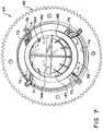
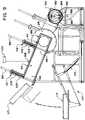
Figure 1 is an isometric view of an apparatus according to one embodiment of the invention.Figure 2 is an isometric view of the apparatus from the opposite side.Figure 3 is a top plan view thereof, partly in section.Figure 4 is a side elevational view thereof, partly in section.Figure 5 is a sectional view on the line 5-5 ofFigure 4 .Figure 6 is an isometric view of the microwave window assembly on the vacuum chamber.Figures 7 and8 are isometric views of the rotatable cylindrical cage, containing a basket.Figure 9 is an end view of the apparatus, partly in section.- In general terms, the
dehydrating apparatus 20 has avacuum chamber 22 within which an organic material in acylindrical container 38 is dehydrated, amicrowave generator 56, anequilibration chamber 150 for cooling the dehydrated material at reduced pressure, aloading module 36 to load containers into the vacuum chamber, atransfer module 42 to transfer containers from the vacuum chamber to the equilibration chamber, and anunloading module 154. - Each of the
loading module 36,transfer module 42 andunloading module 154 has a pair of airlocks, respectively101 and102,130 and111, and164 and170. These permit the containers to be, respectively, loaded into the vacuum chamber, transferred from the vacuum chamber to the equilibration chamber, and unloaded from the equilibration chamber, while maintaining those chambers at the reduced pressures required for the dehydrating process. The structure of each of the airlocks is the same, comprising a self-sealing door movable within a housing by the piston of an air cylinder. Lifting the door opens it and allows a container to pass; lowering the door closes it and forms an airtight seal. - The
dehydrating apparatus 20 has avacuum chamber 22 supported by astand 24. Thechamber 22 has acylindrical wall 26, anend cover 28 at theinput end 30 of the chamber and anend cover 32 at thedischarge end 34 of the chamber. Theloading module 36 is supported on astand 37 and connected to theend cover 28 at theinput end 30 forloading containers 38 containing organic materials40 to be dehydrated into thevacuum chamber 22. Thetransfer module 42 supported on astand 43 is connected to theend cover 32 at the opposite,discharge end 34 of the vacuum chamber. Thevacuum chamber 22 is oriented with its longitudinal axis approximately horizontal. Thestands respective wheels 25 arranged onrails 27, facilitating separation of the modules from the vacuum chamber and equilibration chamber for servicing of the apparatus. - The
cylindrical wall 26 of thevacuum chamber 22 has twowindow assemblies Figure 6 , each window assembly has arectangular frame 48 extending from the outside of thewall 26 with aflange 50 at the outer edge of theframe 48. A microwave-transparent window 54 is positioned in the flange. Thewindow 54 is secured in place by aspacer 52 and amicrowave input horn 53, which is attached to thewindow frame flange 50 by means of aflange 55 at the base of theinput horn 53. Theinput horns 53 are operatively attached to amicrowave generator 56 by waveguides (not shown). Themicrowave input horns 53 are rectangular in cross-section at their upper end, the rectangles having ashort side 57 and along side 59. Thelong sides 59 of themicrowave input horns 53 of thewindow assemblies vacuum chamber 22. - An
air inlet port 58 on eachrectangular frame 48, adjacent to thewindows 54, is connected by anair conduit 60 to a source ofcompressed air 62. By these inlet ports, air is blown across thewindows 54, inside thevacuum chamber 22. Alternatively theinlet port 58 is connected to a source of another gas, for example an inert gas such as nitrogen or helium. - A rotatable
cylindrical cage 64 inside the vacuum chamber is adapted to receive and rotate thecontainers 38. Thecylindrical cage 64 is an open-sided structure. Thecylindrical cage 64 has aring gear longitudinal members 70. Circumferential support rings72 are attached to thelongitudinal members 70 at approximately one-quarter and three-quarters of the distance between the ring gears66,68. Thecylindrical cage 64 is reinforced bysteel frame rods 73 affixed to thelongitudinal members 70 along their length and by steel frame rings74 adjacent to the ring gears66,68 and at the longitudinal midpoint of the cylindrical cage. The cylindrical cage accommodates sixcontainers 38 end to end. For purposes of illustration, the cylindrical cage and vacuum chamber are shown in the drawings as holding four containers only. The cylindrical cage and vacuum chamber can be made in a size to hold any selected number of containers. - A pair of gears at each end of the vacuum chamber support the cylindrical cage. Two gears76,78 are mounted on the
end cover 28 at theinput end 30 of the vacuum chamber to engage thering gear 66, and two gears (one of which is indicated byreference numeral 80 inFig. 4 ) are mounted on theend cover 32 at thedischarge end 34 to engage theother ring gear 68. Onegear respective motor cylindrical cage 64 about its longitudinal, horizontal axis, within the vacuum chamber. - The
loading module 36 has acontainer input chamber 88 adjacent to theend cover 28 of the vacuum chamber with anopening 90 through theend cover 28 that is aligned with the open, receivingend 92 of thecylindrical cage 64, such that acontainer 38 in theinput chamber 88 may be pushed through theopening 90 into thecylindrical cage 64. Theloading module 36 has aloading channel 94 for the introduction of containers into theinput chamber 88. Theloading channel 94 has aninner end 96 adjacent to theinput chamber 88 and anouter end 98. Anairlock assembly 101 is provided at theouter end 98 of theloading channel 94. It comprises a self-sealingdoor 103 which is movable within ahousing 105 to close theloading channel 94 with an airtight seal when in its lowered position, and to open the loading channel when in its raised position. Theloading channel 94 is separated from theinput chamber 88 by anairlock assembly 102. This assembly has a self-sealingdoor 104 which is movable within ahousing 106 by a piston in anair cylinder 99 to close theloading channel 94 with an airtight seal when in its lowered position, and to open the loading channel, when in its raised position, to allow acontainer 38 to pass into theinput chamber 88. The input module includes acontainer lifting assembly 107, powered by anair cylinder 109 and atray 117. The tray is arranged to hold one or more containers and to lift the containers up to theouter end 98 of theloading channel 94. The loading channel is sloped downward, from theairlock 101 to theinput chamber 88, so that a container, placed in the loading channel with its longitudinal axis oriented horizontally and parallel to the longitudinal axis of thecylindrical cage 64, can roll into theinput chamber 88 under the force of gravity. - The
loading channel 94 has avacuum port 108 connected by a conduit to avacuum system 100, for evacuating the loading channel. Avacuum port 110 is provided in theinput chamber 88, connected by a conduit to thevacuum system 100, for evacuating the input chamber and the vacuum chamber. Additional vacuum ports (not shown) coupled to thevacuum system 100 are provided in thevacuum chamber 22 for the evacuation thereof, including the evacuation of the air that is blown into the vacuum chamber through theair inlet ports 58, and removal of moisture that evaporates from the organic material during dehydration.Condensers 41 are provided in thevacuum system 100 to remove moisture from it. - An
air cylinder 112 with a container-pushingpiston 114 is affixed to theinput chamber 88. Thepiston 114 is movable between a position extending into theinput chamber 88 and a retracted position. The piston can accordingly movecontainers 38 out of theinput chamber 88 and through thecylindrical cage 64 andvacuum chamber 22, as discussed below. - The
container transfer module 42 is provided to transfer containers of dehydrated material from the vacuum chamber to theequilibration chamber 150. Thetransfer module 42 has acontainer discharge chamber 116 affixed to theend cover 32 of thevacuum chamber 22, with anopening 118 through theend cover 32 that is aligned with theopen discharge end 120 of thecylindrical cage 64, such that acontainer 38 in the cylindrical cage may be pushed through theopening 118 into thedischarge chamber 116. Thetransfer module 42 has atransfer channel 122 for the removal of containers from thedischarge chamber 116. Thetransfer channel 122 is separated from thecontainer discharge chamber 116 by theairlock assembly 130 having a self-sealingdoor 132 which is movable within ahousing 134 for closing to form an airtight seal, and to open thetransfer channel 122, when in its raised position, to allow acontainer 38 to pass from thedischarge chamber 116 into thetransfer channel 122. Thetransfer module 42 has aninput chamber 151 which is separated from thetransfer channel 122 by the airlock assembly111. This assembly has a self-sealing door113 which is movable with ahousing 115 to open and to seal thetransfer channel 122. The transfer channel has avacuum port 136, connected by a conduit to avacuum system 97, for evacuation of the transfer channel. The transfer channel is sloped downward, from thedischarge chamber 116 to theinput chamber 151 so that a container in thedischarge chamber 116 can roll into theinput chamber 151 under the force of gravity. - The
input chamber 151 has anopening 153 aligned with the open, receivingend 155 of theequilibration chamber 150, such that acontainer 38 in theinput chamber 151 may be pushed through theopening 153 into the equilibration chamber. Anair cylinder 157 with a container-pushingpiston 159 is affixed to theinput chamber 151. Thepiston 159 is movable between a position extending into theinput chamber 151 and a retracted position. The piston can movecontainers 38 out of theinput chamber 151 and into the equilibration chamber. - The
equilibration chamber 150 serves the function of cooling the dehydrated material before the material is exposed to atmospheric pressure. This improves the appearance and texture of the product. Cooling is done by having the dehydrated product remain in the low pressure of the equilibration chamber for a sufficient dwell time to cool, for example for 15 minutes. No auxiliary cooling, e.g. by means of refrigeration, is required in the equilibration chamber. The equilibration chamber may be described as a low pressure cooling chamber. - The equilibration
chamber unloading module 154 has acontainer discharge chamber 156 adjacent to thedischarge end 158 of the equilibration chamber. Thedischarge chamber 156 has anopening 160 that is aligned with the open, discharge end158 of the equilibration chamber, such that acontainer 38 that is moved through the equilibration chamber, as discussed below, passes through theopening 160 into thedischarge chamber 156. Theunloading module 154 has an unloadingchannel 162 for the removal of containers from thedischarge chamber 156. The unloadingchannel 162 is separated from thedischarge chamber 156 by theairlock assembly 164 having a self-sealingdoor 166 which is movable within ahousing 168 for closing to form an airtight seal and for opening the unloadingchannel 162, when its raised position, to allow a container to pass from thedischarge chamber 156 into the unloadingchannel 162. Thesecond airlock assembly 170 is provided at the exit end of the unloadingchannel 162. This second airlock assembly has a self-sealingdoor 172 which is movable within ahousing 174, to seal the unloading channel and to open to allow a container in the unloading channel to exit theunloading module 154. The unloadingchannel 162 is sloped downward, from thedischarge chamber 156 to thesecond airlock assembly 170, so that a container in the discharge chamber can roll through and out of the unloading module under the force of gravity. Containers exiting the unloading module can be received onto a tray or moving belt, etc., or by an operator. - A
vacuum port 176 in the unloadingchannel 162, connected by a conduit to thevacuum system 97, permitting the evacuation of the unloading channel. Thedischarge chamber 156 also has avacuum port 178 connected by a conduit to thevacuum system 97, for evacuating the discharge chamber and the equilibration chamber. Additional vacuum ports (not shown), connected to avacuum system 97, are provided in the equilibration chamber for the evacuation thereof, including the removal of residual moisture that evaporates from the organic material. Acondenser 41 is provided to remove moisture in thevacuum system 97. Thevacuum system 97 for the equilibration chamber is separate from thevacuum system 100 of the vacuum chamber, as these two chambers may be operated at different pressures. - Means are provided within the equilibration chamber for rotating the
containers 38 and for moving them from the receivingend 155 to thedischarge end 158. Twobasket support rollers 180 extend along the length of the equilibration chamber, adjacent its lower side, for rotation about an axis parallel to the longitudinal axis of the equilibration chamber. A drive motor (not shown) is arranged for driving one of therollers 180, providing for the rotation of the roller and accordingly of containers supported on therollers 180 about an axis parallel to the longitudinal axis of the equilibration chamber. Two sets ofroller wheels 182 are mounted on liftablelongitudinal brackets 184 for rotation about an axis perpendicular to the longitudinal axis of the equilibration chamber. Thebrackets 184 extend along the length of the equilibration chamber, adjacent its lower side, between thesupport rollers 180. Three liftingbrackets 186, one near each end and one at the middle of the equilibration chamber, below thelongitudinal brackets 184, are arranged for vertical movement bypistons 188. Actuation of thepistons 188 raises the liftingbrackets 186, which in turn raises thelongitudinal brackets 184 so that theroller wheels 182 engage thecontainers 38 and lift them off of thesupport rollers 182, permitting longitudinal movement of the baskets through the equilibration chamber on theroller wheels 182, as further described below. - It will be understood that the dehydrating
apparatus 20 includes computerized control systems for the operation of the airlocks, motors, pistons, microwave generator, vacuum pumps and container lifter. - The
container 38 is a basket made of high density polyethylene, with acylindrical side wall 138, aclosed bottom wall 140 and aremovable lid 142. The side wall, bottom wall and lid are perforated by a plurality ofholes 144 for the escape of water vapor from the organic material during the dehydration process. The basket has a plurality ofsupport ribs 147 and asupport ring 145. Longitudinally-extendingdivider walls 146 divide the interior space into four segments, to promote the tumbling of the materials in the baskets, as the baskets rotate in the vacuum chamber. - The container may alternatively comprise a disposable sock-like sleeve fitted over a cylindrical frame, the sleeve forming the bottom wall and cylindrical side wall of the container, which has a removable lid fitted to the frame. The sleeve is perforated or made of netting. This form of container has the advantage that, when it becomes soiled, only the frame and lid need to be cleaned, the disposable sock being removed and replaced.
- At the beginning of a cycle of operation of the dehydrating
apparatus 20, theairlocks vacuum chamber 22 is evacuated by thevacuum system 100, i.e. the pressure is reduced to a pressure that is less than atmospheric, via the vacuum system. Absolute pressures in the vacuum chamber in the range of 20 to 100 mm of mercury are suitable for dehydrating most organic materials. Theequilibration chamber 150 is evacuated by itsvacuum system 97, to an absolute pressure of30 mm of mercury or less, preferably as low as about 1 mm of mercury. Thepiston 114 is in its retracted position. Themotors cylindrical cage 64. Theairlock 101 is open and theloading channel 94 is at atmospheric pressure. Themicrowave generator 56 is actuated, radiating microwave energy through thewindows 54 into the vacuum chamber. Air (or nitrogen or helium) is blown across thewindows 54, inside the vacuum chamber, through theair inlet ports 58. - A
container 38 of organic material to be dehydrated is placed on the liftingassembly 107 and theair cylinder 109 is actuated to lift the container to the open end of thecontainer loading channel 94, aligned with its longitudinal axis parallel to the longitudinal axis of the vacuum chamber. The container rolls under the force of gravity down the loading channel to rest against theairlock plate 104. Theairlock 101 is closed and vacuum is applied at thevacuum port 108 to evacuate the loading channel, to the same pressure as thevacuum chamber 22. - The
airlock plate 104 is then raised, permitting the container to roll, under the force of gravity, into theinput chamber 88. Theair cylinder 112 is actuated to move thepiston 114 into the input chamber, pushing the container through theopening 90 in theend cover 28 and into the rotatingcylindrical cage 64, supported by and sliding along thelongitudinal members 70. Thecontainer 38 is rotated about its longitudinal axis by the rotation of thecylindrical cage 64, tumbling the material in the container as the material is being dehydrated. - To load a second container, the
airlock plate 104 is lowered, sealing theloading channel 94. The vacuum in the loading channel is broken, the pressure in the loading channel returning to atmospheric. Theairlock 101 is then opened. The basket-pushingpiston 114 is retracted. The second container is loaded in the same manner as the first container. Once the second container is in theinput chamber 88, thepiston 114 pushes it into thecylindrical cage 64. This pushes the second container against the first container, displacing the first container farther down thecylindrical cage 64 towards the discharge end34 of the vacuum chamber, by the length of one container. The process is repeated by loading additional containers in the same manner, each container displacing the previously-loaded ones in thecylindrical cage 64 by one container-length, until the cylindrical cage is full and the forward end of the first-loaded container is adjacent to theopening 118 in theend cover 32 leading to thedischarge chamber 116. The loading of one more container displaces this first-loaded container into thedischarge chamber 116, the length of thecylindrical cage 64 being such that it holds a whole number of containers end-to-end. Insertion of one more container thus fully displaces the first-loaded container from the cylindrical cage and vacuum chamber. This discharged container rolls under the force of gravity and comes to rest against thedoor 132 of theairlock assembly 130. Thetransfer channel 122 is evacuated to the same pressure as the vacuum chamber. Theairlock door 132 is raised, allowing the discharged container to roll into the transfer channel. Theairlock 130 is then closed and the pressure in the transfer channel is adjusted to equal the lower pressure in the equilibration chamber. The airlock111 is then opened, allowing the container to roll into theinput chamber 151. In order for the equilibration chamber to receive the container from theinput chamber 151, thepistons 188 are actuated to raise the liftingbrackets 186, thebrackets 184 and theroller wheels 182. Theair cylinder 157 is then actuated, causing thepiston 159 to push the container into the receivingend 155 of the equilibration chamber. The container is received onto theroller wheels 182. Then theroller wheels 182 are lowered, causing the container to rest on thesupport rollers 180. These rollers rotate, causing the rotation of the container about its longitudinal axis at about 6 rpm. Thepiston 159 is retracted, the airlock111 is closed, the pressure in the transfer channel is adjusted to equal the pressure in the vacuum chamber, and theairlock 130 is opened. A second container is then transferred from thedischarge chamber 116 to theinput chamber 151 in the same manner. Theroller wheels 182 are then raised, lifting the container off thesupport rollers 180. Theair cylinder 157 is actuated, pushing the container that is in the input chamber into the equilibration chamber. That container pushes against the first container, moving it farther into the equilibration chamber by one container-length. The process is repeated with additional containers until the equilibration chamber is full, holding ten containers. Insertion of one more container pushes the first-loaded container out of thedischarge end 158 of the equilibration chamber and into thedischarge chamber 156. The unloadingchannel 162 is evacuated to the same pressure as the equilibration chamber. Theairlock 164 is then opened, permitting the container to roll into the unloadingchannel 162 and rest against thedoor 172 of theairlock assembly 170. Theairlock 164 is then closed. The vacuum in the unloadingchannel 162 is then broken and the unloading channel is brought to atmospheric pressure. Theairlock 170 is opened and the container of cooled, dehydrated organic material is removed from the apparatus. Theairlock 170 is then closed and the unloadingchannel 162 is evacuated, in preparation for the unloading of the next container. The apparatus is operated on a continuous throughput basis. - An apparatus according to the invention has a vacuum chamber with a length of 2.5 meters and an inner diameter of 0.96 meters. The inside diameter of the rotatable cylindrical cage is 0.50 meters. The baskets are made of polyethylene and have a length of 0.44 meters and an outer diameter of 0.44 meters. The rotatable cylindrical cage holds six baskets end-to-end. The equilibration chamber has a length of 3.6 meters and an inner diameter of 0.61 meters, and holds ten baskets end-to-end. The microwave generator has a power output of 50,000 watts. Each basket is loaded with 5 kg of partially dehydrated blueberries. The vacuum chamber is evacuated to an absolute pressure of 60 mm of mercury. The equilibration chamber is evacuated to an absolute pressure of 30 mm of mercury or less. Compressed air is blown across the inside of each of the two microwave-transparent windows at a rate of 20 liters per minute. The rotatable cylindrical cage is rotated at a speed of 6 rpm. The apparatus is operated according to the method described above. Baskets of partially dehydrated blueberries to be further dehydrated are fed continuously into the vacuum chamber. The dwell time of a given basket within the chamber is about 10 minutes and about 15 minutes within the equilibration chamber.
- The blueberries that are fed into the apparatus have been predried by other means to a moisture content between about 25% and 75 % moisture. If some moisture is not first removed from fresh blueberries they may be too soft to agitate in the rotating basket of the apparatus without crushing. Pre-drying toughens up the blueberries and helps avoid crushing. The microwave vacuum-drying process of the invention reduces the moisture content to about 5% to 15% final moisture. The dried blueberries retain a puffed appearance and are close in volume to the fresh berries. Puffing occurs because of the expansion of steam evaporated within the berry during microwave vacuum-drying. The puffed appearance is retained after the vacuum is released and the product is removed from the apparatus.
- Although the invention has been described in terms of various embodiments, it is not intended that the invention be limited to these embodiments. Various modifications within the scope of the invention will be apparent to those skilled in the art. The scope of the invention is defined by the claims that follow.
- 20
- dehydrating apparatus
- 22
- vacuum chamber
- 24
- stand
- 25
- wheels of stand
- 26
- cylindrical wall of vacuum chamber
- 27
- support rails
- 28
- end cover at input end of vacuum chamber
- 30
- input end of vacuum chamber
- 32
- end cover at discharge end of vacuum chamber
- 34
- discharge end of vacuum chamber
- 36
- loading module
- 37
- stand of loading module
- 38
- container
- 40
- organic material
- 41
- condenser
- 42
- transfer module
- 43
- stand of unloading module
- 44, 46
- window assemblies on vacuum chamber
- 48
- frame of window
- 50
- window frame flange
- 52
- window spacer
- 53
- microwave input horn
- 54
- windows
- 55
- flange on input horn
- 56
- microwave generator
- 57
- short side of input horn entrance
- 58
- air inlet ports
- 59
- long side of input horn entrance
- 60
- air conduit
- 62
- compressed air source
- 64
- cylindrical cage
- 66, 68
- ring gears
- 70
- longitudinal members of cylindrical cage
- 72
- cylindrical cage support rings
- 73
- steel frame rods of cylindrical cage
- 74
- steel frame rings of cylindrical cage
- 76, 78
- gears at input end of vacuum chamber
- 80
- gear at discharge end of vacuum chamber
- 84, 86
- gear drive motors
- 88
- container input chamber
- 90
- opening in input end cover of vacuum chamber
- 92
- receiving end of cylindrical cage
- 94
- container loading channel
- 96
- inner end of loading channel
- 97
- vacuum system for equilibration chamber
- 98
- outer end of loading channel
- 99
- air cylinder
- 100
- vacuum system for vacuum chamber
- 101
- outer airlock assembly of loading channel
- 102
- inner airlock assembly of loading channel
- 103
- door of
airlock 101 - 104
- door of
airlock 102 - 105
- housing of
airlock 101 - 106
- housing of
airlock 102 - 107
- container lifting assembly
- 108
- vacuum port in loading channel
- 109
- air cylinder of container lifting assembly
- 110
- vacuum port in loading channel
- 111
- airlock assembly in transfer module
- 112
- air cylinder of loading chamber
- 113
- door of airlock assembly
- 114
- piston of
air cylinder 112 - 115
- housing of airlock 111
- 116
- discharge chamber
- 118
- opening in end cover at discharge end of vacuum chamber
- 120
- discharge end of
cylindrical cage 64 - 122
- transfer channel
- 130
- airlock assembly of unloading channel
- 132
- door of
airlock 130 - 134
- housing of
airlock 130 - 136
- vacuum port in transfer channel
- 138
- side wall of container
- 140
- bottom wall of container
- 142
- lid of container
- 144
- holes in container
- 145
- ribs of container
- 146
- divider walls of container
- 147
- support ring of container
- 150
- equilibration chamber
- 151
- input chamber of equilibration chamber
- 153
- opening in input chamber
- 154
- unloading module
- 155
- receiving end of equilibration chamber
- 156
- discharge chamber
- 157
- air cylinder of input chamber
- 158
- discharge end of equilibration chamber
- 159
- piston of
air cylinder 157 - 160
- opening in discharge chamber
- 162
- unloading channel
- 164
- discharge airlock assembly
- 166
- door of
airlock 164 - 168
- housing of
airlock 164 - 170
- exit airlock assembly
- 172
- door of
airlock 170 - 174
- housing of
airlock 170 - 176
- vacuum port in unloading channel
- 178
- vacuum port in equilibration chamber
- 180
- longitudinal support rollers
- 182
- roller wheels
- 184
- bracket for wheels
- 186
- lifting brackets
- 188
- pistons
Claims (16)
- An apparatus (20) for dehydrating organic material (40), comprising:(a) a vacuum chamber (22) having an input end (30) for introduction of a container (38) for the organic material into the vacuum chamber and a discharge end (24) for removal of the container;(b) a microwave generator (56);(c) a microwave-transparent window (54) for transmission of microwave radiation from the microwave generator (56) into the vacuum chamber (22);(d) means for reducing pressure (100) inside the vacuum chamber (22);(e) means (36) for loading the container (38) into the input end (30) of the vacuum chamber (22);(f) means (76, 78, 68, 80, 84, 86) for rotating the container inside the vacuum chamber (22) about a horizontal axis;(g) means (112, 114) for moving the rotating container (38) through the vacuum chamber (22) from the input end (30) to the discharge end (34) thereof; and(h) means (42) for unloading the container (38) of dehydrated organic material from the vacuum chamber at the discharge end (34) thereof.
- An apparatus according to claim 1, further comprising means (150) for cooling the dehydrated organic material at a pressure less than atmospheric.
- An apparatus according to claim 2, wherein the means for cooling comprises:an equilibration chamber (150) having an input end (155) for introduction of the container (38) of dehydrated organic material into the equilibration chamber and a discharge end (158) for removal of the container; andmeans (97) for reducing pressure inside the equilibration chamber.
- An apparatus according to claim 3, wherein the apparatus further comprises:means (42) for loading the container (38) of dehydrated organic material into the input end (155) of the equilibration chamber (150);means (180, 184, 186, 188) for rotating the container of dehydrated organic material inside the equilibration chamber;means (157, 159, 182) for moving the container (38) of dehydrated organic material through the equilibration chamber from the input end (155) to the discharge end (158) thereof; andmeans (154) for unloading the container of dehydrated organic material from the equilibration chamber at the discharge end (158) thereof.
- An apparatus according to claim 4, wherein the means (180, 184, 186, 188) for rotating the container (38) of dehydrated material inside the equilibration chamber (150) rotates the container about a horizontal axis.
- An apparatus according to any one of claims 1-5, wherein the means for rotating the container inside the vacuum chamber comprises:a rotatable cylindrical cage (64) having a ring gear (66, 68) at each respective end thereof; andgears (80, 84, 86) at the input and discharge ends (30, 34) of the vacuum chamber to support and rotate the respective ring gear (66, 68).
- An apparatus according to any one of claims 1 to 6, wherein the means for moving the container (38) through the vacuum chamber (22) comprises a piston (114) arranged to push the container into the vacuum chamber, and a plurality of rails (70) for slidable support of the container through the vacuum chamber.
- An apparatus according to any one of claims 1 to 6, wherein the means for loading the container into the input end of the vacuum chamber comprises:a container input chamber (88) which is open to the vacuum chamber (22) at the input end (30) of the vacuum chamber;a loading channel (94) having a first end (98) for receiving the container and a second end (96) adjacent to the container input chamber;a first airlock (101) at the first end (98) of the loading channel and a second airlock (102) at the second end (96) of the loading channel; anda piston (114) arranged to push the container (38) from the container input chamber (88) into the vacuum chamber (22).
- An apparatus according to claim 8, wherein the loading channel (94) is sloped downward from the first end (98) to the second end (96) thereof.
- An apparatus according to claim 1, wherein the means for unloading the container of dehydrated organic material from the vacuum chamber at the discharge end (34) thereof comprises:a discharge chamber (116) which is open to the vacuum chamber (22) at the discharge end (34) of the vacuum chamber;an unloading channel (122) having a first end adjacent to the discharge chamber (116) and a second end; anda first airlock (130) at the first end of the unloading channel (122) and a second airlock (111) at the second end of the unloading channel.
- An apparatus according to claim 10, wherein the unloading channel (122) is sloped downward from the first end to the second end thereof.
- A method for dehydrating an organic material, comprising the steps of:(a) providing a microwave-transparent container (38) holding the organic material (40) to be dehydrated;(b) introducing the container into a vacuum chamber (22) at an input end (30) thereof, the vacuum chamber being at a pressure less than atmospheric;(c) rotating the container (38) inside the vacuum chamber (22) about a horizontal axis;(d) moving the rotating container through the vacuum chamber from the input end (30) to a discharge end (34) thereof while applying microwave radiation to dehydrate the organic material; and(e) removing the container (38) of dehydrated organic material from the vacuum chamber at the discharge end (34).
- A method according to claim 12, further comprising after step (e) the step of cooling the dehydrated organic material at a pressure less than atmospheric.
- A method according to claim 13, wherein cooling the dehydrated organic material comprises the steps of:loading the container (38) of dehydrated organic material into the input end (155) of an equilibration chamber (150), the equilibration chamber being at the pressure less than atmospheric;rotating the container of dehydrated organic material inside the equilibration chamber;moving the container of dehydrated organic material through the equilibration chamber from the input end (155) to a discharge end (158) thereof, while allowing the dehydrated organic material to cool; andunloading the container of cooled, dehydrated organic material from the equilibration chamber (150) at the discharge end (158) thereof.
- A method according to claim 14, wherein the container of dehydrated material inside the equilibration chamber is rotated about a horizontal axis.
- A method according to claim 14, wherein the pressure in the equilibration chamber (150) is less than the pressure in the vacuum chamber (22).
Priority Applications (3)
| Application Number | Priority Date | Filing Date | Title |
|---|---|---|---|
| HRP20191831TTHRP20191831T1 (en) | 2007-10-15 | 2008-10-15 | Apparatus and method for microwave vacuum-drying of organic materials |
| EP11168254.8AEP2377411B1 (en) | 2007-10-15 | 2008-10-15 | Apparatus and method for microwave vacuum-drying of organic materials |
| PL08838608TPL2200458T3 (en) | 2007-10-15 | 2008-10-15 | Apparatus and method for microwave vacuum-drying of organic materials |
Applications Claiming Priority (2)
| Application Number | Priority Date | Filing Date | Title |
|---|---|---|---|
| US98007007P | 2007-10-15 | 2007-10-15 | |
| PCT/CA2008/001811WO2009049409A1 (en) | 2007-10-15 | 2008-10-15 | Apparatus and method for microwave vacuum-drying of organic materials |
Related Child Applications (2)
| Application Number | Title | Priority Date | Filing Date |
|---|---|---|---|
| EP11168254.8ADivisionEP2377411B1 (en) | 2007-10-15 | 2008-10-15 | Apparatus and method for microwave vacuum-drying of organic materials |
| EP11168254.8ADivision-IntoEP2377411B1 (en) | 2007-10-15 | 2008-10-15 | Apparatus and method for microwave vacuum-drying of organic materials |
Publications (3)
| Publication Number | Publication Date |
|---|---|
| EP2200458A1 EP2200458A1 (en) | 2010-06-30 |
| EP2200458A4 EP2200458A4 (en) | 2010-12-01 |
| EP2200458B1true EP2200458B1 (en) | 2019-08-14 |
Family
ID=40566955
Family Applications (2)
| Application Number | Title | Priority Date | Filing Date |
|---|---|---|---|
| EP11168254.8AActiveEP2377411B1 (en) | 2007-10-15 | 2008-10-15 | Apparatus and method for microwave vacuum-drying of organic materials |
| EP08838608.1AActiveEP2200458B1 (en) | 2007-10-15 | 2008-10-15 | Apparatus and method for microwave vacuum-drying of organic materials |
Family Applications Before (1)
| Application Number | Title | Priority Date | Filing Date |
|---|---|---|---|
| EP11168254.8AActiveEP2377411B1 (en) | 2007-10-15 | 2008-10-15 | Apparatus and method for microwave vacuum-drying of organic materials |
Country Status (18)
| Country | Link |
|---|---|
| US (1) | US10178873B2 (en) |
| EP (2) | EP2377411B1 (en) |
| JP (2) | JP6110052B2 (en) |
| CN (1) | CN101820780B (en) |
| AU (1) | AU2008314458B2 (en) |
| BR (1) | BRPI0818421B1 (en) |
| CA (1) | CA2678089C (en) |
| CL (1) | CL2010000398A1 (en) |
| DK (1) | DK2200458T3 (en) |
| ES (1) | ES2746477T3 (en) |
| HR (1) | HRP20191831T1 (en) |
| HU (1) | HUE047217T2 (en) |
| LT (1) | LT2200458T (en) |
| MX (2) | MX355861B (en) |
| NZ (1) | NZ584266A (en) |
| PL (1) | PL2200458T3 (en) |
| PT (1) | PT2200458T (en) |
| WO (1) | WO2009049409A1 (en) |
Families Citing this family (33)
| Publication number | Priority date | Publication date | Assignee | Title |
|---|---|---|---|---|
| DE202007001123U1 (en)* | 2007-01-25 | 2007-06-06 | KRÜGER, Günter | Plant for drying organic matter |
| CN102149813B (en) | 2008-09-12 | 2015-05-27 | 能波公司 | Apparatus and method for dehydrating biological materials with freezing and microwaving |
| EP2424970A4 (en)* | 2009-04-28 | 2014-08-13 | Enwave Corp | Apparatus and method for dehydrating biological materials |
| EP2408322B1 (en)* | 2009-06-18 | 2012-08-22 | Päx Food AG | Mvd method and device for drying and buffering organic moist products |
| JP5713596B2 (en)* | 2009-09-29 | 2015-05-07 | キヤノン株式会社 | Method for producing electrophotographic photosensitive member |
| EP2525675B1 (en)* | 2010-01-18 | 2015-04-15 | Enwave Corporation | Microwave vacuum-drying of organic materials |
| JP5489930B2 (en)* | 2010-09-14 | 2014-05-14 | グンゼ株式会社 | Drying equipment |
| CN102766910B (en)* | 2012-07-09 | 2014-11-19 | 北京中棉工程技术有限公司 | Integrated seed cotton vacuum drying and cleaning processing system and operating method thereof |
| EP2689833A3 (en)* | 2012-07-27 | 2015-05-13 | Marion Mixers, Inc. | Mixing apparatus |
| WO2014085897A1 (en) | 2012-12-07 | 2014-06-12 | Enwave Corporation | Microwave vacuum-drying of organic materials |
| CN103245170A (en)* | 2013-05-21 | 2013-08-14 | 锡矿山闪星锑业有限责任公司 | Ethylene glycol antimony acetate vacuum microwave drying method |
| US9782470B2 (en) | 2013-10-16 | 2017-10-10 | Merck Sharp & Dohme Corp. | Method of obtaining thermostable dried vaccine formulations |
| WO2015057548A1 (en) | 2013-10-16 | 2015-04-23 | Merck Sharp & Dohme Corp | Thermostable respiratory synctial virus (rsv) vaccine compositions |
| WO2015057540A1 (en) | 2013-10-16 | 2015-04-23 | Merck Sharp & Dohme Corp. | Method of microwave vacuum drying spherical-shaped pellets of biological materials |
| US9615604B2 (en) | 2014-02-06 | 2017-04-11 | David Russick | Food waste dehydrator |
| CN103884155B (en)* | 2014-04-02 | 2016-02-10 | 中国农业大学 | The spouted drying equipment of Multicarity continuous microwave vacuum |
| WO2015188248A1 (en) | 2014-06-11 | 2015-12-17 | Enwave Corporation | Microwave vacuum-drying of organic materials |
| CN104188091B (en)* | 2014-08-25 | 2016-03-02 | 云南昆船第一机械有限公司 | A kind of conveying device of microwave expansion equipment |
| WO2017011939A1 (en)* | 2015-07-17 | 2017-01-26 | 周川 | Modular continuous microwave freeze-drying chamber and microwave freeze-drying device comprising freeze-drying chamber |
| US10542768B1 (en) | 2015-11-18 | 2020-01-28 | Tyson Foods, Inc. | Method and apparatus for drying food item |
| FR3046518B1 (en)* | 2016-01-06 | 2021-04-02 | Inovfruit | SINGLE-MODE MICROWAVE APPLICATOR, DEVICE AND METHOD FOR THERMAL TREATMENT OF PRODUCTS |
| US11104502B2 (en)* | 2016-03-01 | 2021-08-31 | Jeffrey S. Melcher | Multi-function compact appliance and methods for a food or item in a container with a container storage technology |
| RU2616434C1 (en)* | 2016-04-12 | 2017-04-14 | Федеральное государственное бюджетное научное учреждение "Всероссийский научно-исследовательский институт механизации льноводства" (ФГБНУ ВНИИМЛ) | Dryer for agricultural crops |
| WO2018187851A1 (en)* | 2017-04-13 | 2018-10-18 | Enwave Corporation | Method of making dried porous food products |
| US10747968B2 (en) | 2017-11-22 | 2020-08-18 | Jeffrey S. Melcher | Wireless device and selective user control and management of a wireless device and data |
| CN109676996B (en)* | 2018-12-28 | 2023-12-15 | 洛阳维尔健生物工程有限公司 | Tabletting and drying integrated machine for producing chewable tablets |
| WO2020176961A1 (en)* | 2019-03-05 | 2020-09-10 | Enwave Corporation | Vacuum microwave drying with higher pressure step |
| WO2021013863A1 (en) | 2019-07-23 | 2021-01-28 | Frieslandcampina Nederland B.V. | Dairy-based snack food product |
| US12357001B2 (en)* | 2020-02-28 | 2025-07-15 | Enwave Corporation | Vacuum chamber apparatus with single roller for rotating container |
| US20230288140A1 (en)* | 2020-06-05 | 2023-09-14 | Merck Sharp & Dohme Llc | Apparatus and method of microwave vacuum drying sterile products |
| US11717772B2 (en) | 2020-11-19 | 2023-08-08 | 1140522 B.C. Ltd. | Condensate separator system for vacuum microwave dehydrators |
| CN113280581B (en)* | 2021-05-31 | 2022-01-25 | 蚌埠学院 | Vacuum microwave low-temperature dehydration equipment for meat |
| CN114838562A (en)* | 2022-05-11 | 2022-08-02 | 常州蓝翼飞机装备制造有限公司 | Method for removing gas micro-water in welded gas cylinder |
Family Cites Families (54)
| Publication number | Priority date | Publication date | Assignee | Title |
|---|---|---|---|---|
| US1969101A (en)* | 1929-04-18 | 1934-08-07 | Goodrich Co B F | Manufacture of rubber articles |
| US2900477A (en) | 1956-09-21 | 1959-08-18 | Westinghouse Electric Corp | Circuit interrupters |
| US3174229A (en)* | 1962-02-26 | 1965-03-23 | Pennsalt Chemicals Corp | Drying apparatus of elongated heated conduit type |
| US3308332A (en)* | 1963-07-16 | 1967-03-07 | Varian Associates | Radio frequency window cooling structure and transmission devices using same |
| US4045639A (en) | 1973-01-16 | 1977-08-30 | Food Processing Systems Corporation | Continuous microwave and vacuum dryer |
| US4033048A (en) | 1976-01-12 | 1977-07-05 | Clayton Van Ike | Freeze drying apparatus |
| US4169408A (en)* | 1977-02-10 | 1979-10-02 | Fmc Corporation | Continuous pressure cooker and cooler with controlled liquid flow |
| US4329554A (en) | 1980-01-07 | 1982-05-11 | Huber William J | Loadbreak arc snuffing device |
| US4330946A (en) | 1980-09-23 | 1982-05-25 | Ralph S. Tillitt | High efficiency material drying |
| US4347670A (en) | 1980-11-28 | 1982-09-07 | Mcdonnell Douglas Corporation | Apparatus and process for drying granular products |
| US4389794A (en) | 1980-12-23 | 1983-06-28 | Bitterly Jack G | Vacuum chamber and method of creating a vacuum |
| JPS5980691U (en)* | 1982-11-24 | 1984-05-31 | ハウス食品工業株式会社 | Decompression microwave dryer |
| CA1217376A (en) | 1982-12-28 | 1987-02-03 | Kazumitsu Taga | Dehydrated food product and method of producing same |
| JPH06101999B2 (en) | 1985-12-16 | 1994-12-14 | 株式会社芝浦製作所 | Vacuum expansion and drying device |
| JPS6326175A (en) | 1986-07-18 | 1988-02-03 | Matsushita Electric Ind Co Ltd | Light-shielding hood device for LCD television receivers |
| JPS6376439A (en) | 1986-09-19 | 1988-04-06 | Hitachi Ltd | Drying method |
| JPS63223481A (en)* | 1987-03-13 | 1988-09-16 | 日本真空技術株式会社 | Drier for cereals |
| US4882851A (en) | 1987-04-13 | 1989-11-28 | The Fitzpatrick Co. | Apparatus and method for batch drying using a microwave vacuum system |
| US5020237A (en)* | 1989-01-03 | 1991-06-04 | The J. M. Smucker Company | Method and apparatus for dehydrating fruit |
| DE3916479C1 (en) | 1989-05-20 | 1990-08-30 | Otto Dr.Rer.Nat. Moebus | Drying biological and pharmaceutical prods. etc. - includes drying prods. on a porous floor in an evacuable tank using overhead microwave heater |
| JPH0423995U (en)* | 1990-06-18 | 1992-02-26 | ||
| US5334402A (en)* | 1990-08-03 | 1994-08-02 | Kansas State University Research Foundation | Heat processing of a product |
| JPH0816586B2 (en) | 1990-10-27 | 1996-02-21 | 京都府茶協同組合 | Microwave irradiation continuous drying equipment |
| US5211808A (en) | 1990-11-13 | 1993-05-18 | Savant Instruments | Microwave heating in a vacuum centrifugal concentrator |
| JPH0661232B2 (en)* | 1990-11-30 | 1994-08-17 | ダイエーサービス株式会社 | Dryer |
| JP2632612B2 (en) | 1991-09-02 | 1997-07-23 | 株式会社 アサヒ産業 | Method and apparatus for producing pregelatinized rice |
| US5388345A (en) | 1993-11-04 | 1995-02-14 | Corning Incorporated | Dielectric drying of metal structures |
| US5980962A (en) | 1994-07-11 | 1999-11-09 | Microwave Processing Technologies Pty. Limited | Process of and apparatus for providing at least a partial barrier to moisture vapor transfer through the surface of a material and/or for removing moisture from a material |
| JP2815089B2 (en)* | 1994-09-01 | 1998-10-27 | 株式会社ニチレイ | Solid sterilizer |
| US5676989A (en)* | 1996-03-29 | 1997-10-14 | The University Of British Columbia | Production of chips |
| US5672370A (en) | 1996-04-16 | 1997-09-30 | The University Of British Columbia | Method of producing a dried krill product |
| AUPO705697A0 (en)* | 1997-05-28 | 1997-06-19 | Australian Rural Dehydration Enterprise Pty Ltd | Dehydration plant |
| US6128321A (en) | 1997-12-19 | 2000-10-03 | Alcatel Usa Sourcing, L.P. | System and method for centrally-managing switching functions |
| DE19804386C2 (en)* | 1998-02-04 | 1999-12-30 | Ttp Ingenieurbuero | Method and device for drying or heat treating products, in particular with the aid of microwave radiation, and banana chips and banana powder produced therewith |
| US5956865A (en) | 1998-05-20 | 1999-09-28 | The University Of British Columbia | Process for drying herbs |
| US5962057A (en) | 1998-06-30 | 1999-10-05 | The University Of Bristish Columbia | Process for drying mango and pineapples |
| JP2000274941A (en) | 1999-03-19 | 2000-10-06 | Morita Econos Ltd | Heat treatment apparatus for water-containing refuse |
| US6128831A (en) | 1999-06-03 | 2000-10-10 | Durance; Timothy Douglas | Process for drying medicinal plants |
| US6956865B1 (en) | 2000-01-07 | 2005-10-18 | Cisco Technology, Inc. | Technique for dynamically adjusting lookahead time for channel map messages to achieve optimal packet performance over an access network |
| JP2001330369A (en) | 2000-05-25 | 2001-11-30 | Mitsubishi Heavy Ind Ltd | Microwave leakage-preventing structure of microwave wave rotary drying machine |
| WO2002102241A2 (en) | 2001-06-15 | 2002-12-27 | The University Of Houston System | Thin film optical detectors for retinal implantation and methods for making and using same |
| CA2354300C (en) | 2001-07-30 | 2010-07-06 | The University Of British Columbia | Process for dehydration of berries |
| DE10138938A1 (en)* | 2001-08-08 | 2003-02-20 | Bosch Gmbh Robert | Method for sterilizing containers in a plasma treatment chamber, involves movement of the containers and/or the plasma excitation units so that a plasma is produced in required container regions |
| PL354373A1 (en) | 2002-06-10 | 2003-12-15 | Prod Handlowa Paula Sp Z Oo Fa | Method of drying dielectric materials and appliance for drying dielectric materials |
| DE10320043B4 (en)* | 2003-05-06 | 2006-04-13 | Eastman Kodak Company | Apparatus and method for handling of printing material within a microwave device |
| WO2005100891A1 (en)* | 2004-04-12 | 2005-10-27 | Kitakyushu Foundation For The Advancement Of Industry, Science And Technology | Method and apparatus for reduced pressure drying using microwave |
| CN2713823Y (en) | 2004-07-01 | 2005-08-03 | 邹峰 | Vacuum microwave dewater unit |
| TWI251472B (en) | 2005-06-02 | 2006-03-21 | Kurotech Co Ltd | System for drying and sterilizing foods and method therefor |
| JP2007024379A (en) | 2005-07-14 | 2007-02-01 | Hiroshi Otsuki | Drier, and drier operating method |
| CN2870478Y (en) | 2005-12-21 | 2007-02-21 | 中国农业机械化科学研究院 | Continuous microwave vacuum drying sweller |
| CA2557628A1 (en) | 2006-08-30 | 2008-02-29 | Environmental Waste International, Inc. | Method and apparatus for the dehydration and/or sterilization of organic materials |
| US20080181994A1 (en)* | 2007-01-30 | 2008-07-31 | Frito-Lay North America, Inc. | Apparatus and Method for Vacuum Microwave Drying of Food Products |
| JP4207168B2 (en) | 2007-03-02 | 2009-01-14 | 好高 青山 | Projection bolt welding apparatus and welding method |
| ES2691709T3 (en)* | 2007-05-25 | 2018-11-28 | Tiax Llc | Fuel combustion |
- 2008
- 2008-10-15DKDK08838608Tpatent/DK2200458T3/enactive
- 2008-10-15MXMX2013001809Apatent/MX355861B/enunknown
- 2008-10-15LTLTEP08838608.1Tpatent/LT2200458T/enunknown
- 2008-10-15MXMX2010004095Apatent/MX366382B/enactiveIP Right Grant
- 2008-10-15EPEP11168254.8Apatent/EP2377411B1/enactiveActive
- 2008-10-15CACA2678089Apatent/CA2678089C/enactiveActive
- 2008-10-15EPEP08838608.1Apatent/EP2200458B1/enactiveActive
- 2008-10-15ESES08838608Tpatent/ES2746477T3/enactiveActive
- 2008-10-15HRHRP20191831TTpatent/HRP20191831T1/enunknown
- 2008-10-15HUHUE08838608Apatent/HUE047217T2/enunknown
- 2008-10-15NZNZ584266Apatent/NZ584266A/enunknown
- 2008-10-15PTPT88386081Tpatent/PT2200458T/enunknown
- 2008-10-15PLPL08838608Tpatent/PL2200458T3/enunknown
- 2008-10-15BRBRPI0818421-6Apatent/BRPI0818421B1/ennot_activeIP Right Cessation
- 2008-10-15CNCN2008801113902Apatent/CN101820780B/ennot_activeExpired - Fee Related
- 2008-10-15WOPCT/CA2008/001811patent/WO2009049409A1/enactiveApplication Filing
- 2008-10-15AUAU2008314458Apatent/AU2008314458B2/enactiveActive
- 2008-10-15USUS12/682,989patent/US10178873B2/enactiveActive
- 2008-10-15JPJP2010528255Apatent/JP6110052B2/enactiveActive
- 2010
- 2010-04-21CLCL2010000398Apatent/CL2010000398A1/enunknown
- 2015
- 2015-01-05JPJP2015000200Apatent/JP6177814B2/enactiveActive
Non-Patent Citations (1)
| Title |
|---|
| None* |
Also Published As
| Publication number | Publication date |
|---|---|
| CN101820780B (en) | 2013-07-10 |
| ES2746477T3 (en) | 2020-03-06 |
| AU2008314458A1 (en) | 2009-04-23 |
| US20100218395A1 (en) | 2010-09-02 |
| JP6177814B2 (en) | 2017-08-09 |
| MX366382B (en) | 2019-07-08 |
| PT2200458T (en) | 2019-10-10 |
| JP2015061998A (en) | 2015-04-02 |
| EP2200458A1 (en) | 2010-06-30 |
| LT2200458T (en) | 2019-09-10 |
| CA2678089A1 (en) | 2009-04-23 |
| PL2200458T3 (en) | 2020-02-28 |
| CN101820780A (en) | 2010-09-01 |
| JP2011501086A (en) | 2011-01-06 |
| WO2009049409A1 (en) | 2009-04-23 |
| HRP20191831T1 (en) | 2019-12-27 |
| BRPI0818421A2 (en) | 2014-10-07 |
| AU2008314458B2 (en) | 2013-12-19 |
| EP2377411B1 (en) | 2017-03-29 |
| HUE047217T2 (en) | 2020-04-28 |
| MX355861B (en) | 2018-05-03 |
| MX2010004095A (en) | 2010-06-25 |
| DK2200458T3 (en) | 2019-11-04 |
| CA2678089C (en) | 2011-10-04 |
| CL2010000398A1 (en) | 2011-01-07 |
| JP6110052B2 (en) | 2017-04-05 |
| EP2377411A1 (en) | 2011-10-19 |
| US10178873B2 (en) | 2019-01-15 |
| NZ584266A (en) | 2012-01-12 |
| BRPI0818421B1 (en) | 2018-06-12 |
| HK1143718A1 (en) | 2011-01-14 |
| EP2200458A4 (en) | 2010-12-01 |
| AU2008314458A2 (en) | 2010-06-10 |
Similar Documents
| Publication | Publication Date | Title |
|---|---|---|
| EP2200458B1 (en) | Apparatus and method for microwave vacuum-drying of organic materials | |
| JP6042996B2 (en) | Microwave vacuum drying of organic matter | |
| CA2950188C (en) | Microwave vacuum-drying of organic materials | |
| HK1143718B (en) | Apparatus and method for microwave vacuum-drying of organic materials | |
| US20230288140A1 (en) | Apparatus and method of microwave vacuum drying sterile products | |
| HK1208524B (en) | Microwave vacuum-drying of organic materials | |
| NZ706088B2 (en) | Microwave vacuum-drying of organic materials |
Legal Events
| Date | Code | Title | Description |
|---|---|---|---|
| PUAI | Public reference made under article 153(3) epc to a published international application that has entered the european phase | Free format text:ORIGINAL CODE: 0009012 | |
| 17P | Request for examination filed | Effective date:20100413 | |
| AK | Designated contracting states | Kind code of ref document:A1 Designated state(s):AT BE BG CH CY CZ DE DK EE ES FI FR GB GR HR HU IE IS IT LI LT LU LV MC MT NL NO PL PT RO SE SI SK TR | |
| AX | Request for extension of the european patent | Extension state:AL BA MK RS | |
| RIN1 | Information on inventor provided before grant (corrected) | Inventor name:FU, JUN Inventor name:DURANCE, TIMOTHY, D. Inventor name:YAGHMAEE, PARASTOO | |
| A4 | Supplementary search report drawn up and despatched | Effective date:20101104 | |
| DAX | Request for extension of the european patent (deleted) | ||
| 17Q | First examination report despatched | Effective date:20160824 | |
| RAP1 | Party data changed (applicant data changed or rights of an application transferred) | Owner name:ENWAVE CORPORATION | |
| STAA | Information on the status of an ep patent application or granted ep patent | Free format text:STATUS: EXAMINATION IS IN PROGRESS | |
| REG | Reference to a national code | Ref country code:DE Ref legal event code:R079 Ref document number:602008060931 Country of ref document:DE Free format text:PREVIOUS MAIN CLASS: A23L0003540000 Ipc:F26B0017300000 | |
| RIC1 | Information provided on ipc code assigned before grant | Ipc:A23B 7/02 20060101ALI20190222BHEP Ipc:F26B 15/14 20060101ALI20190222BHEP Ipc:A23L 3/01 20060101ALI20190222BHEP Ipc:A23L 3/54 20060101ALI20190222BHEP Ipc:F26B 5/04 20060101ALI20190222BHEP Ipc:F26B 3/347 20060101ALI20190222BHEP Ipc:A23B 7/01 20060101ALI20190222BHEP Ipc:A23L 3/3418 20060101ALI20190222BHEP Ipc:A23B 7/148 20060101ALI20190222BHEP Ipc:F26B 17/30 20060101AFI20190222BHEP | |
| GRAP | Despatch of communication of intention to grant a patent | Free format text:ORIGINAL CODE: EPIDOSNIGR1 | |
| STAA | Information on the status of an ep patent application or granted ep patent | Free format text:STATUS: GRANT OF PATENT IS INTENDED | |
| INTG | Intention to grant announced | Effective date:20190410 | |
| GRAS | Grant fee paid | Free format text:ORIGINAL CODE: EPIDOSNIGR3 | |
| GRAA | (expected) grant | Free format text:ORIGINAL CODE: 0009210 | |
| STAA | Information on the status of an ep patent application or granted ep patent | Free format text:STATUS: THE PATENT HAS BEEN GRANTED | |
| RAP1 | Party data changed (applicant data changed or rights of an application transferred) | Owner name:ENWAVE CORPORATION | |
| RIN1 | Information on inventor provided before grant (corrected) | Inventor name:DURANCE, TIMOTHY, D. Inventor name:YAGHMAEE, PARASTOO Inventor name:FU, JUN | |
| AK | Designated contracting states | Kind code of ref document:B1 Designated state(s):AT BE BG CH CY CZ DE DK EE ES FI FR GB GR HR HU IE IS IT LI LT LU LV MC MT NL NO PL PT RO SE SI SK TR | |
| REG | Reference to a national code | Ref country code:GB Ref legal event code:FG4D | |
| REG | Reference to a national code | Ref country code:CH Ref legal event code:EP Ref country code:AT Ref legal event code:REF Ref document number:1167525 Country of ref document:AT Kind code of ref document:T Effective date:20190815 | |
| REG | Reference to a national code | Ref country code:CH Ref legal event code:NV Representative=s name:ING. MARCO ZARDI C/O M. ZARDI AND CO. S.A., CH | |
| REG | Reference to a national code | Ref country code:IE Ref legal event code:FG4D | |
| REG | Reference to a national code | Ref country code:DE Ref legal event code:R096 Ref document number:602008060931 Country of ref document:DE | |
| REG | Reference to a national code | Ref country code:PT Ref legal event code:SC4A Ref document number:2200458 Country of ref document:PT Date of ref document:20191010 Kind code of ref document:T Free format text:AVAILABILITY OF NATIONAL TRANSLATION Effective date:20190919 Ref country code:HR Ref legal event code:TUEP Ref document number:P20191831 Country of ref document:HR | |
| PGFP | Annual fee paid to national office [announced via postgrant information from national office to epo] | Ref country code:LT Payment date:20190826 Year of fee payment:12 | |
| REG | Reference to a national code | Ref country code:DK Ref legal event code:T3 Effective date:20191031 | |
| REG | Reference to a national code | Ref country code:NL Ref legal event code:FP | |
| REG | Reference to a national code | Ref country code:SE Ref legal event code:TRGR | |
| PGFP | Annual fee paid to national office [announced via postgrant information from national office to epo] | Ref country code:LU Payment date:20191025 Year of fee payment:12 | |
| REG | Reference to a national code | Ref country code:NO Ref legal event code:T2 Effective date:20190814 | |
| REG | Reference to a national code | Ref country code:HR Ref legal event code:ODRP Ref document number:P20191831 Country of ref document:HR Payment date:20191015 Year of fee payment:12 | |
| REG | Reference to a national code | Ref country code:HR Ref legal event code:T1PR Ref document number:P20191831 Country of ref document:HR | |
| REG | Reference to a national code | Ref country code:EE Ref legal event code:FG4A Ref document number:E018426 Country of ref document:EE Effective date:20191107 | |
| REG | Reference to a national code | Ref country code:GR Ref legal event code:EP Ref document number:20190403050 Country of ref document:GR Effective date:20200122 | |
| PG25 | Lapsed in a contracting state [announced via postgrant information from national office to epo] | Ref country code:BG Free format text:LAPSE BECAUSE OF FAILURE TO SUBMIT A TRANSLATION OF THE DESCRIPTION OR TO PAY THE FEE WITHIN THE PRESCRIBED TIME-LIMIT Effective date:20191114 | |
| PGFP | Annual fee paid to national office [announced via postgrant information from national office to epo] | Ref country code:NO Payment date:20191010 Year of fee payment:12 Ref country code:MC Payment date:20191022 Year of fee payment:12 Ref country code:CZ Payment date:20191008 Year of fee payment:12 | |
| PGFP | Annual fee paid to national office [announced via postgrant information from national office to epo] | Ref country code:LV Payment date:20191029 Year of fee payment:12 Ref country code:HR Payment date:20191015 Year of fee payment:12 Ref country code:EE Payment date:20191008 Year of fee payment:12 | |
| REG | Reference to a national code | Ref country code:ES Ref legal event code:FG2A Ref document number:2746477 Country of ref document:ES Kind code of ref document:T3 Effective date:20200306 | |
| PGFP | Annual fee paid to national office [announced via postgrant information from national office to epo] | Ref country code:AT Payment date:20191009 Year of fee payment:12 | |
| REG | Reference to a national code | Ref country code:HU Ref legal event code:AG4A Ref document number:E047217 Country of ref document:HU | |
| PG25 | Lapsed in a contracting state [announced via postgrant information from national office to epo] | Ref country code:RO Free format text:LAPSE BECAUSE OF FAILURE TO SUBMIT A TRANSLATION OF THE DESCRIPTION OR TO PAY THE FEE WITHIN THE PRESCRIBED TIME-LIMIT Effective date:20190814 | |
| PGFP | Annual fee paid to national office [announced via postgrant information from national office to epo] | Ref country code:PL Payment date:20191010 Year of fee payment:12 | |
| PG25 | Lapsed in a contracting state [announced via postgrant information from national office to epo] | Ref country code:SK Free format text:LAPSE BECAUSE OF FAILURE TO SUBMIT A TRANSLATION OF THE DESCRIPTION OR TO PAY THE FEE WITHIN THE PRESCRIBED TIME-LIMIT Effective date:20190814 | |
| REG | Reference to a national code | Ref country code:DE Ref legal event code:R097 Ref document number:602008060931 Country of ref document:DE | |
| PLBE | No opposition filed within time limit | Free format text:ORIGINAL CODE: 0009261 | |
| STAA | Information on the status of an ep patent application or granted ep patent | Free format text:STATUS: NO OPPOSITION FILED WITHIN TIME LIMIT | |
| 26N | No opposition filed | Effective date:20200603 | |
| PG25 | Lapsed in a contracting state [announced via postgrant information from national office to epo] | Ref country code:SI Free format text:LAPSE BECAUSE OF FAILURE TO SUBMIT A TRANSLATION OF THE DESCRIPTION OR TO PAY THE FEE WITHIN THE PRESCRIBED TIME-LIMIT Effective date:20190814 | |
| REG | Reference to a national code | Ref country code:HR Ref legal event code:PBON Ref document number:P20191831 Country of ref document:HR Effective date:20201015 | |
| REG | Reference to a national code | Ref country code:EE Ref legal event code:MM4A Ref document number:E018426 Country of ref document:EE Effective date:20201031 | |
| REG | Reference to a national code | Ref country code:NO Ref legal event code:MMEP | |
| PG25 | Lapsed in a contracting state [announced via postgrant information from national office to epo] | Ref country code:CY Free format text:LAPSE BECAUSE OF FAILURE TO SUBMIT A TRANSLATION OF THE DESCRIPTION OR TO PAY THE FEE WITHIN THE PRESCRIBED TIME-LIMIT Effective date:20190814 | |
| REG | Reference to a national code | Ref country code:AT Ref legal event code:MM01 Ref document number:1167525 Country of ref document:AT Kind code of ref document:T Effective date:20201015 | |
| PG25 | Lapsed in a contracting state [announced via postgrant information from national office to epo] | Ref country code:MC Free format text:LAPSE BECAUSE OF NON-PAYMENT OF DUE FEES Effective date:20201103 Ref country code:LU Free format text:LAPSE BECAUSE OF NON-PAYMENT OF DUE FEES Effective date:20201015 | |
| PG25 | Lapsed in a contracting state [announced via postgrant information from national office to epo] | Ref country code:CZ Free format text:LAPSE BECAUSE OF NON-PAYMENT OF DUE FEES Effective date:20201015 Ref country code:EE Free format text:LAPSE BECAUSE OF NON-PAYMENT OF DUE FEES Effective date:20201031 Ref country code:NO Free format text:LAPSE BECAUSE OF NON-PAYMENT OF DUE FEES Effective date:20201031 Ref country code:HR Free format text:LAPSE BECAUSE OF NON-PAYMENT OF DUE FEES Effective date:20201015 Ref country code:MT Free format text:LAPSE BECAUSE OF FAILURE TO SUBMIT A TRANSLATION OF THE DESCRIPTION OR TO PAY THE FEE WITHIN THE PRESCRIBED TIME-LIMIT Effective date:20190814 | |
| REG | Reference to a national code | Ref country code:LT Ref legal event code:MM4D Effective date:20201015 | |
| PG25 | Lapsed in a contracting state [announced via postgrant information from national office to epo] | Ref country code:LV Free format text:LAPSE BECAUSE OF NON-PAYMENT OF DUE FEES Effective date:20201015 Ref country code:AT Free format text:LAPSE BECAUSE OF NON-PAYMENT OF DUE FEES Effective date:20201015 | |
| PG25 | Lapsed in a contracting state [announced via postgrant information from national office to epo] | Ref country code:LT Free format text:LAPSE BECAUSE OF NON-PAYMENT OF DUE FEES Effective date:20201015 | |
| PG25 | Lapsed in a contracting state [announced via postgrant information from national office to epo] | Ref country code:PL Free format text:LAPSE BECAUSE OF NON-PAYMENT OF DUE FEES Effective date:20201015 | |
| REG | Reference to a national code | Ref country code:AT Ref legal event code:UEP Ref document number:1167525 Country of ref document:AT Kind code of ref document:T Effective date:20190814 | |
| PGFP | Annual fee paid to national office [announced via postgrant information from national office to epo] | Ref country code:NL Payment date:20241026 Year of fee payment:17 | |
| PGFP | Annual fee paid to national office [announced via postgrant information from national office to epo] | Ref country code:HU Payment date:20241003 Year of fee payment:17 | |
| PGFP | Annual fee paid to national office [announced via postgrant information from national office to epo] | Ref country code:DE Payment date:20241029 Year of fee payment:17 | |
| PGFP | Annual fee paid to national office [announced via postgrant information from national office to epo] | Ref country code:DK Payment date:20241025 Year of fee payment:17 | |
| PGFP | Annual fee paid to national office [announced via postgrant information from national office to epo] | Ref country code:BE Payment date:20241028 Year of fee payment:17 Ref country code:FI Payment date:20241025 Year of fee payment:17 Ref country code:GR Payment date:20241029 Year of fee payment:17 | |
| PGFP | Annual fee paid to national office [announced via postgrant information from national office to epo] | Ref country code:GB Payment date:20241028 Year of fee payment:17 | |
| PGFP | Annual fee paid to national office [announced via postgrant information from national office to epo] | Ref country code:FR Payment date:20241025 Year of fee payment:17 Ref country code:IS Payment date:20241008 Year of fee payment:17 | |
| PGFP | Annual fee paid to national office [announced via postgrant information from national office to epo] | Ref country code:IE Payment date:20241028 Year of fee payment:17 | |
| PGFP | Annual fee paid to national office [announced via postgrant information from national office to epo] | Ref country code:IT Payment date:20241021 Year of fee payment:17 Ref country code:ES Payment date:20241104 Year of fee payment:17 | |
| PGFP | Annual fee paid to national office [announced via postgrant information from national office to epo] | Ref country code:SE Payment date:20241027 Year of fee payment:17 | |
| PGFP | Annual fee paid to national office [announced via postgrant information from national office to epo] | Ref country code:CH Payment date:20241101 Year of fee payment:17 | |
| PGFP | Annual fee paid to national office [announced via postgrant information from national office to epo] | Ref country code:TR Payment date:20241010 Year of fee payment:17 | |
| PGFP | Annual fee paid to national office [announced via postgrant information from national office to epo] | Ref country code:PT Payment date:20250924 Year of fee payment:18 |