EP2198796A1 - Bone screw - Google Patents
Bone screwDownload PDFInfo
- Publication number
- EP2198796A1 EP2198796A1EP08405311AEP08405311AEP2198796A1EP 2198796 A1EP2198796 A1EP 2198796A1EP 08405311 AEP08405311 AEP 08405311AEP 08405311 AEP08405311 AEP 08405311AEP 2198796 A1EP2198796 A1EP 2198796A1
- Authority
- EP
- European Patent Office
- Prior art keywords
- screw
- bone
- core
- shaft
- sleeve
- Prior art date
- Legal status (The legal status is an assumption and is not a legal conclusion. Google has not performed a legal analysis and makes no representation as to the accuracy of the status listed.)
- Withdrawn
Links
- 210000000988bone and boneAnatomy0.000titleclaimsabstractdescription35
- 239000004696Poly ether ether ketoneSubstances0.000claimsabstractdescription23
- 229920002530polyetherether ketonePolymers0.000claimsabstractdescription23
- 239000000463materialSubstances0.000claimsabstractdescription15
- RTAQQCXQSZGOHL-UHFFFAOYSA-NTitaniumChemical compound[Ti]RTAQQCXQSZGOHL-UHFFFAOYSA-N0.000claimsabstractdescription10
- 239000010936titaniumSubstances0.000claimsabstractdescription10
- 229910052719titaniumInorganic materials0.000claimsabstractdescription10
- 229910052751metalInorganic materials0.000claimsabstractdescription8
- 239000002184metalSubstances0.000claimsabstractdescription8
- 229920003023plasticPolymers0.000claimsabstractdescription7
- 229910000831SteelInorganic materials0.000claimsabstractdescription6
- 239000010959steelSubstances0.000claimsabstractdescription6
- 239000004033plasticSubstances0.000claimsabstractdescription4
- JUPQTSLXMOCDHR-UHFFFAOYSA-Nbenzene-1,4-diol;bis(4-fluorophenyl)methanoneChemical compoundOC1=CC=C(O)C=C1.C1=CC(F)=CC=C1C(=O)C1=CC=C(F)C=C1JUPQTSLXMOCDHR-UHFFFAOYSA-N0.000claimsdescription21
- 210000002436femur neckAnatomy0.000claimsdescription2
- 238000010008shearingMethods0.000claimsdescription2
- 239000000835fiberSubstances0.000description9
- 238000010079rubber tappingMethods0.000description4
- 238000004026adhesive bondingMethods0.000description3
- TZCXTZWJZNENPQ-UHFFFAOYSA-Lbarium sulfateChemical compound[Ba+2].[O-]S([O-])(=O)=OTZCXTZWJZNENPQ-UHFFFAOYSA-L0.000description2
- 238000005553drillingMethods0.000description2
- 229920000049Carbon (fiber)Polymers0.000description1
- 239000004698PolyethyleneSubstances0.000description1
- 238000004873anchoringMethods0.000description1
- 239000004917carbon fiberSubstances0.000description1
- 238000000576coating methodMethods0.000description1
- 229910052588hydroxylapatiteInorganic materials0.000description1
- 239000007943implantSubstances0.000description1
- 238000003780insertionMethods0.000description1
- 230000037431insertionEffects0.000description1
- 238000004519manufacturing processMethods0.000description1
- VNWKTOKETHGBQD-UHFFFAOYSA-NmethaneChemical compoundCVNWKTOKETHGBQD-UHFFFAOYSA-N0.000description1
- 230000001097osteosynthetic effectEffects0.000description1
- XYJRXVWERLGGKC-UHFFFAOYSA-Dpentacalcium;hydroxide;triphosphateChemical compound[OH-].[Ca+2].[Ca+2].[Ca+2].[Ca+2].[Ca+2].[O-]P([O-])([O-])=O.[O-]P([O-])([O-])=O.[O-]P([O-])([O-])=OXYJRXVWERLGGKC-UHFFFAOYSA-D0.000description1
- 229920001643poly(ether ketone)Polymers0.000description1
- 229920000515polycarbonatePolymers0.000description1
- 239000004417polycarbonateSubstances0.000description1
- -1polyethylenePolymers0.000description1
- 229920000573polyethylenePolymers0.000description1
- 239000012783reinforcing fiberSubstances0.000description1
- 239000013589supplementSubstances0.000description1
- 229910052715tantalumInorganic materials0.000description1
- GUVRBAGPIYLISA-UHFFFAOYSA-Ntantalum atomChemical compound[Ta]GUVRBAGPIYLISA-UHFFFAOYSA-N0.000description1
Images
Classifications
- A—HUMAN NECESSITIES
- A61—MEDICAL OR VETERINARY SCIENCE; HYGIENE
- A61B—DIAGNOSIS; SURGERY; IDENTIFICATION
- A61B17/00—Surgical instruments, devices or methods
- A61B17/56—Surgical instruments or methods for treatment of bones or joints; Devices specially adapted therefor
- A61B17/58—Surgical instruments or methods for treatment of bones or joints; Devices specially adapted therefor for osteosynthesis, e.g. bone plates, screws or setting implements
- A61B17/68—Internal fixation devices, including fasteners and spinal fixators, even if a part thereof projects from the skin
- A61B17/84—Fasteners therefor or fasteners being internal fixation devices
- A61B17/86—Pins or screws or threaded wires; nuts therefor
- A61B17/866—Material or manufacture
- A—HUMAN NECESSITIES
- A61—MEDICAL OR VETERINARY SCIENCE; HYGIENE
- A61B—DIAGNOSIS; SURGERY; IDENTIFICATION
- A61B17/00—Surgical instruments, devices or methods
- A61B17/56—Surgical instruments or methods for treatment of bones or joints; Devices specially adapted therefor
- A61B17/58—Surgical instruments or methods for treatment of bones or joints; Devices specially adapted therefor for osteosynthesis, e.g. bone plates, screws or setting implements
- A61B17/68—Internal fixation devices, including fasteners and spinal fixators, even if a part thereof projects from the skin
- A61B17/84—Fasteners therefor or fasteners being internal fixation devices
- A61B17/86—Pins or screws or threaded wires; nuts therefor
- A61B17/8685—Pins or screws or threaded wires; nuts therefor comprising multiple separate parts
- A—HUMAN NECESSITIES
- A61—MEDICAL OR VETERINARY SCIENCE; HYGIENE
- A61B—DIAGNOSIS; SURGERY; IDENTIFICATION
- A61B17/00—Surgical instruments, devices or methods
- A61B17/56—Surgical instruments or methods for treatment of bones or joints; Devices specially adapted therefor
- A61B17/58—Surgical instruments or methods for treatment of bones or joints; Devices specially adapted therefor for osteosynthesis, e.g. bone plates, screws or setting implements
- A61B17/68—Internal fixation devices, including fasteners and spinal fixators, even if a part thereof projects from the skin
- A61B17/84—Fasteners therefor or fasteners being internal fixation devices
- A61B17/86—Pins or screws or threaded wires; nuts therefor
- A61B17/8625—Shanks, i.e. parts contacting bone tissue
- A61B17/8635—Tips of screws
- A—HUMAN NECESSITIES
- A61—MEDICAL OR VETERINARY SCIENCE; HYGIENE
- A61B—DIAGNOSIS; SURGERY; IDENTIFICATION
- A61B17/00—Surgical instruments, devices or methods
- A61B17/56—Surgical instruments or methods for treatment of bones or joints; Devices specially adapted therefor
- A61B17/58—Surgical instruments or methods for treatment of bones or joints; Devices specially adapted therefor for osteosynthesis, e.g. bone plates, screws or setting implements
- A61B17/68—Internal fixation devices, including fasteners and spinal fixators, even if a part thereof projects from the skin
- A61B17/84—Fasteners therefor or fasteners being internal fixation devices
- A61B17/86—Pins or screws or threaded wires; nuts therefor
- A61B17/864—Pins or screws or threaded wires; nuts therefor hollow, e.g. with socket or cannulated
- A—HUMAN NECESSITIES
- A61—MEDICAL OR VETERINARY SCIENCE; HYGIENE
- A61B—DIAGNOSIS; SURGERY; IDENTIFICATION
- A61B17/00—Surgical instruments, devices or methods
- A61B2017/00831—Material properties
- A61B2017/00902—Material properties transparent or translucent
- A61B2017/00915—Material properties transparent or translucent for radioactive radiation
- A61B2017/0092—Material properties transparent or translucent for radioactive radiation for X-rays
Definitions
- the present inventionrelates to a bone screw having a screw shank which has a tip and is concentric with a screw longitudinal axis and which is to be anchored in a bone or bone part and having a bolt head attached to the screw shaft and engaging means.
- Bone screws of this typehave long been known. They serve, for example, for osteosynthetic bone fixation. Such screws serve in particular for anchoring a plate or a connecting rod to a spinal column. The screws are stressed in this case, for example, by a clamping connection between the screw and a connecting rod or to a plate.
- a bone screw of this kindis for example from the US 5,466,237 known. This is used to attach a connecting rod to a spine. The connecting rod is thereby clamped between the screw head and a nut.
- the EP 0 507 162 Adiscloses a bone screw used to secure a bone plate to a spine. By means of a sleeve, the bone screw is held in the bone plate.
- the EP 1 191 891 Adiscloses a bone screw having an axially two-piece screw head. This should facilitate the insertion of a screwdriver into the screw head.
- the aforementioned bone screwsare made of metal, especially titanium. These have a high strength, so they when screwing and when connecting with are highly resilient an implant.
- the disadvantage hereis the lack of X-ray transparency.
- the inventionhas for its object to provide a bone screw of the type mentioned, which is further or at least partially X-ray transparent, but which is still reliable.
- the objectis achieved in a generic bone screw in that the screw shaft is essentially made of a transparent X-ray plastic and that at least one load-bearing area has a part, this part is made of a different material than that of a core, which substantially the screw shaft forms.
- the X-ray transparency of the bone screw according to the inventionresults from the manufacture of the screw shaft from an X-ray-transparent plastic, for example PEEK or fiber-reinforced PEEK. Fiber-reinforced PEEK and PEEK are X-ray transparent and have a comparatively high strength. However, fiber reinforced PEEK is also relatively brittle at the same time.
- a screw shaft made of fiber reinforced PEEKis possible despite this brittleness, since at least one load-bearing area has a part made of a different material.
- This materialis metal or PEEK.
- This partis preferably arranged on the screw head and has the said attack means. If the said part is made of metal, then the bone screw is not transparent to X-rays only in the region of the screw head.
- Such a screwcan be screwed as in a conventional screw made of titanium on the screw head, for example by means of a screwdriver and clamped.
- a load-bearing areais an area which is particularly stressed, in particular the screw head and / or the screw tip.
- said partis arranged at the tip of the screw shank.
- This partis particularly threaded and allows for high drilling or thread cutting properties.
- the drill bitcan also be designed self-tapping.
- the bone screw according to the inventionis largely X-ray transparent in the area of the screw shaft.
- the said partis sleeve-shaped according to an embodiment of the invention.
- a sleeve-shaped partcan be connected for example by press fitting or by gluing with the screw shaft.
- the sleeveis provided according to an embodiment of the invention for improving the shearing resistance. This sleeve is preferably arranged in a middle region of the screw shaft between the screw head and the tip.
- the partis arranged on the screw head.
- a first partis arranged on the screw head and a second part is arranged on the tip of the screw shank.
- thisresults in very good drilling and thread cutting properties and on the other hand a high load capacity of the bone screw on the screw head.
- the screw shaftis largely transparent to X-rays.
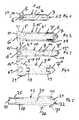
- the FIG. 1shows a screw 1 having a core 3, which forms the screw shaft. This has substantially over its entire length a thread 4 as external thread.
- the shaft 15is coaxial with a helical longitudinal axis 27.
- the core 3consists of an X-ray transparent plastic, for example fiber-reinforced PEEK and in particular carbon fiber reinforced PEEK or PEEK.
- the fibersmay be long fibers or short fibers.
- the shank 15is concentric with a helical longitudinal axis 27.
- other X-ray-transparent and biocompatible plasticssuch as polycarbonate, polyethylene, PEK or PEEKEK are also conceivable.
- a head 14which has a sleeve-shaped part 5, is fastened to the shaft 15.
- This part 5is firmly connected to the core 3, for example by means of a press fit or by gluing.
- This part 5consists of a metal, for example titanium or steel. If the core 3 consists of carbon-fiber-reinforced PEEK, the part 5 may consist of PEEK. Reinforcing fibers are provided in this case only in the core 3.
- the part 5is, for example, in the case of clamping on a plate or a connecting rod of the load-bearing area.
- the head 14has an internal attack 6, for example in the form of a polygonal depression. In principle, however, the attack can also be done outside on Part 5.
- the FIG. 2shows a screw 2, which is designed as a self-tapping screw. It also has a core 3 'made of fiber reinforced PEEK or PEEK.
- the core 3 'has a thread 4', which is also an external thread and which serves to anchor the screw 2 in a bone or a bone part.
- the tip of the shaft 15 'is here formed by a tip 7, which is made of a different material than the core 3'.
- the tip 7may have a thread 28, which may be an external thread and self-tapping.
- the thread 28supplements the thread 4 'in the region of the tip.
- the tip 7is preferably made of a comparatively hard material, for example titanium or steel.
- the attachment of the tip 7 with the core 4 'for example, also by press fit, gluing or screwing example. But there are also other types of connection possible.
- the screw head 14 'is here formed by a sleeve 5', which is also made of a different material than the core 3 '.
- the sleeve 15 'is fixedly connected to the core 3'. It consists for example of metal, in particular titanium or in the case of a core 3 'of fiber-reinforced PEEK made of PEEK.
- the sleeve 5 'is provided with an internal attack 6'.
- the screw head 14 'has a conical thread 31, which is suitable for fastening in a corresponding opening a plate not shown here.
- FIG. 3shows a screw 10 which is suitable as a translaminar pin. It has a 3 "core of fiber reinforced PEEK or PEEK, centered between a 13" tip and a head 14 ", a circumferential recess 16 or groove is incorporated into the core 3", in which a sleeve 9 is inserted. This is fixed at least axially and is made of a different material than the core 3 "The sleeve 9 serves to increase the shear strength in the central region of the core 3". However, this sleeve 9 can also be arranged at a different point of the core 3 ", for example closer to the tip 3" or closer to the head 14.
- the sleeve 9is preferably made of a suitable metal, for example of steel or titanium 17, this sleeve 9 is flush
- the head 14has a sleeve 5" which has an external thread 14 ".
- This sleeve 5is seen to be preferably cylindrical and firmly connected to the core 3", for example glued to this.
- the head 14also has an internal attack 6".
- FIG. 4shows a screw 11, which has a core 3 "', which is also made of PEEK or fiber reinforced PEEK., At a front end of the core 3"' has a recess 19, in which a tip 7 "'is inserted, consisting of a is made much harder material, that of the core 3 "'.
- the core 3 "'has a further recess 18 into which a sleeve 5"' is inserted and fixedly connected to the core 3 "'.
- the sleeve 5"'forms a head 14 "'which has a spherical outer side 29 and an internal attack 6 "'has.
- This screw 11is preferably formed as a self-tapping screw. Between the tip 7 "'and the head 14"' this is transparent to X-rays.
- the head 14 "'is suitable for polyaxial bearing in a peticular system, for example, the head 14"' may be mounted and clamped in a corresponding recess in a plate.
- the sleeve 5 ''consists for example of titanium or a suitable steel.
- FIG. 5discloses a femoral neck screw 12, which is stepped as seen in the longitudinal direction and at a front end has a larger outer diameter with a cylindrical thread 26. It has a core 30 having a cannulation 22 extending in the axial direction. This cannulation 22 is open at both ends of the core 30. At the front pointed end of the core 30 has a circumferential recess 20, in which a sleeve-shaped tip 7 "is inserted. This tip 7" is fixedly connected to the core 30, for example glued. It is conceivable, however Also, for example, a connection 21, which is a press connection or screw connection or the like.
- a sleeve 24Opposite the tip 7 "there is arranged a sleeve 24, which is also fixedly connected to the core 30.
- This sleeve 24has a recess 25 which is formed, for example, as a groove which extends in the axial direction and on which the screw 12 against rotation
- the tip 7 "and sleeve 24are also made of a different material than the core 30.
- the materials or materials already mentioned aboveare provided.
- the tip 7 "and the sleeve 24are made of a material which is substantially harder than the material of the core 30. Die in den FIGS. 1 to 5
- the heads 14 to 14 "'shown in each casecan in principle always be connected to each of the shafts and tips shown FIG.
- cannulation shown 22is also in the in the FIGS. 1 to 4 shown screws conceivable.
- the screwscan also per se suitable markers, for example of tantalum fibers, barium sulfate.
- coatingsare conceivable, for example of titanium or hydroxyapatite.
Landscapes
- Health & Medical Sciences (AREA)
- Orthopedic Medicine & Surgery (AREA)
- Surgery (AREA)
- Life Sciences & Earth Sciences (AREA)
- Heart & Thoracic Surgery (AREA)
- Animal Behavior & Ethology (AREA)
- Engineering & Computer Science (AREA)
- Biomedical Technology (AREA)
- Neurology (AREA)
- Medical Informatics (AREA)
- Molecular Biology (AREA)
- Nuclear Medicine, Radiotherapy & Molecular Imaging (AREA)
- General Health & Medical Sciences (AREA)
- Public Health (AREA)
- Veterinary Medicine (AREA)
- Surgical Instruments (AREA)
- Prostheses (AREA)
- Materials For Medical Uses (AREA)
Abstract
Description
Translated fromGermanDie vorliegende Erfindung betrifft eine Knochenschraube mit einem Schraubenschaft, der eine Spitze aufweist und konzentrisch zu einer Schraubenlängsachse ist und der in einen Knochen oder Knochenteil zu verankern ist und mit einem am Schraubenschaft befestigten und Angriffsmittel aufweisenden Schraubenkopf.The present invention relates to a bone screw having a screw shank which has a tip and is concentric with a screw longitudinal axis and which is to be anchored in a bone or bone part and having a bolt head attached to the screw shaft and engaging means.
Knochenschrauben dieser Art sind seit langem bekannt. Sie dienen beispielsweise zur osteosynthetischen Knochenfixierung. Solche Schrauben dienen hierbei insbesondere zum Verankern einer Platte oder eines Verbindungsstabes an einer Wirbelsäule. Die Schrauben werden hierbei wesentlich beansprucht, beispielsweise durch eine Klemmverbindung zwischen der Schraube und einem Verbindungsstab oder zu einer Platte. Eine Knochenschraube dieser Art ist beispielsweise aus der
Die
Die
Die genannten Knochenschrauben sind aus Metall, insbesondere Titan hergestellt. Diese besitzen eine hohe Festigkeit, sodass sie beim Einschrauben und beim Verbinden mit einem Implantat hochbelastbar sind. Nachteilig ist hier jedoch die mangelnde Röntgentransparenz.The aforementioned bone screws are made of metal, especially titanium. These have a high strength, so they when screwing and when connecting with are highly resilient an implant. The disadvantage here, however, is the lack of X-ray transparency.
Der Erfindung liegt die Aufgabe zugrunde, eine Knochenschraube der genannten Art zu schaffen, die weitergehend oder zumindest bereichsweise röntgentransparent ist, die aber dennoch funktionssicher ist.The invention has for its object to provide a bone screw of the type mentioned, which is further or at least partially X-ray transparent, but which is still reliable.
Die Aufgabe ist bei einer gattungsgemässen Knochenschraube dadurch gelöst, dass der Schraubenschaft im Wesentlichen aus einem röntgentransparenten Kunststoff hergestellt ist und dass wenigstens ein lastentragender Bereich einen Teil aufweist, wobei dieser Teil aus einem anderen Werkstoff hergestellt ist als diejenige eines Kerns, welcher im Wesentlichen den Schraubenschaft bildet. Die Röntgentransparenz der erfindungsgemässen Knochenschraube ergibt sich durch die Herstellung des Schraubenschaftes aus einem röntgentransparenten Kunststoff, beispielsweise PEEK oder faserverstärktem PEEK. Faserverstärktes PEEK und PEEK sind röntgentransparent und besitzt eine vergleichsweise hohe Festigkeit. Faserverstärktes PEEK ist jedoch zugleich vergleichsweise spröd. Ein Schraubenschaft aus faserverstärktem PEEK ist trotz dieser Sprödigkeit jedoch möglich, da wenigstens ein lasttragender Bereich ein Teil aus einem anderen Werkstoff aufweist. Dieser Werkstoff ist Metall oder PEEK. Dieser Teil ist vorzugsweise am Schraubenkopf angeordnet und weist die genannten Angriffsmittel auf. Ist der genannte Teil aus Metall, so ist die Knochenschraube lediglich im Bereich des Schraubenkopfes nicht röntgentransparent. Eine solche Schraube kann wie bei einer üblichen Schraube aus Titan am Schraubenkopf beispielsweise mittels eines Schraubendrehers eingedreht und auch geklemmt werden. Ein lasttragender Bereich ist ein Bereich der besonders beansprucht ist wie insbesondere der Schraubenkopf und/oder die Schraubenspitze.The object is achieved in a generic bone screw in that the screw shaft is essentially made of a transparent X-ray plastic and that at least one load-bearing area has a part, this part is made of a different material than that of a core, which substantially the screw shaft forms. The X-ray transparency of the bone screw according to the invention results from the manufacture of the screw shaft from an X-ray-transparent plastic, for example PEEK or fiber-reinforced PEEK. Fiber-reinforced PEEK and PEEK are X-ray transparent and have a comparatively high strength. However, fiber reinforced PEEK is also relatively brittle at the same time. However, a screw shaft made of fiber reinforced PEEK is possible despite this brittleness, since at least one load-bearing area has a part made of a different material. This material is metal or PEEK. This part is preferably arranged on the screw head and has the said attack means. If the said part is made of metal, then the bone screw is not transparent to X-rays only in the region of the screw head. Such a screw can be screwed as in a conventional screw made of titanium on the screw head, for example by means of a screwdriver and clamped. A load-bearing area is an area which is particularly stressed, in particular the screw head and / or the screw tip.
Nach einer Weiterbildung der Erfindung ist vorgesehen, dass der genannte Teil an der Spitze des Schraubenschaftes angeordnet ist. Dieser Teil ist insbesondere mit einem Gewinde versehen und ermöglicht hohe Bohr- oder Gewindeschneideeigenschaften. Die Bohrspitze kann zudem selbstschneidend ausgebildet werden. Trotzdem ist die erfindungsgemässe Knochenschraube im Bereich des Schraubenschaftes weitgehend röntgentransparent.According to a development of the invention it is provided that said part is arranged at the tip of the screw shank. This part is particularly threaded and allows for high drilling or thread cutting properties. The drill bit can also be designed self-tapping. Nevertheless, the bone screw according to the invention is largely X-ray transparent in the area of the screw shaft.
Der genannte Teil ist gemäss einer Weiterbildung der Erfindung hülsenförmig ausgebildet. Ein solcher hülsenförmiger Teil kann beispielsweise durch Presssitz oder durch Verkleben mit dem Schraubenschaft verbunden werden. Die Hülse ist gemäss einer Weiterbildung der Erfindung zur Verbesserung der Abscherfestigkeit vorgesehen. Diese Hülse vorzugsweise in einem mittleren Bereich des Schraubenschaftes zwischen dem Schraubenkopf und der Spitze angeordnet.The said part is sleeve-shaped according to an embodiment of the invention. Such a sleeve-shaped part can be connected for example by press fitting or by gluing with the screw shaft. The sleeve is provided according to an embodiment of the invention for improving the shearing resistance. This sleeve is preferably arranged in a middle region of the screw shaft between the screw head and the tip.
Vorzugsweise ist der Teil am Schraubenkopf angeordnet. Denkbar ist aber auch eine Ausführung, bei welcher ein erster Teil am Schraubenkopf und ein zweiter Teil an der Spitze des Schraubenschaftes angeordnet sind. Einerseits ergeben sich dadurch sehr gute Bohr- und Gewindeschneideeigenschaften und andererseits eine hohe Belastbarkeit der Knochenschraube am Schraubenkopf. Auch in diesem Fall ist der Schraubenschaft weitgehend röntgentransparent.Preferably, the part is arranged on the screw head. Also conceivable, however, is an embodiment in which a first part is arranged on the screw head and a second part is arranged on the tip of the screw shank. On the one hand this results in very good drilling and thread cutting properties and on the other hand a high load capacity of the bone screw on the screw head. Also in this case, the screw shaft is largely transparent to X-rays.
Ausführungsbeispiele der Erfindung werden nachfolgend anhand der Zeichnung näher erläutert:Embodiments of the invention will be explained in more detail with reference to the drawing:
Es zeigen:
- Figuren 1 - 5
- Jeweils schematisch Längsschnitte durch erfindungsgemässe Schrauben.
- Figures 1 - 5
- In each case, schematic longitudinal sections through screws according to the invention.
Die
Gegenüber der Spitze 13 ist am Schaft 15 ein Kopf 14 befestigt, der einen hülsenförmigen Teil 5 besitzt. Dieser Teil 5 ist fest mit dem Kern 3 verbunden, beispielsweise mittels eines Presssitzes oder durch Verkleben. Dieser Teil 5 besteht aus einem Metall, beispielsweise aus Titan oder Stahl. Besteht der Kern 3 aus kohlenfaserverstärktem PEEK, so kann der Teil 5 aus PEEK bestehen. Verstärkende Fasern sind in diesem Fall lediglich im Kern 3 vorgesehen. Der Teil 5 ist beispielsweise im Fall einer Klemmung an einer Platte oder einem Verbindungsstab der lasttragende Bereich. Zum Einschrauben der Schraube 1 in einen Knochen oder einen Knochenteil besitzt der Kopf 14 einen Innenangriff 6, beispielsweise in der Form einer mehrkantigen Vertiefung. Grundsätzlich kann der Angriff jedoch auch aussen am Teil 5 erfolgen.Opposite the tip 13, a
Die
Der Schraubenkopf 14' wird hier durch eine Hülse 5' gebildet, die ebenfalls aus einem anderen Material hergestellt ist als der Kern 3'. Die Hülse 15' ist fest mit dem Kern 3' verbunden. Sie besteht beispielsweise aus Metall, insbesondere Titan oder im Fall eines Kernes 3' aus faserverstärktem PEEK aus PEEK. Die Hülse 5' ist mit einem Innenangriff 6' versehen. Der Schraubenkopf 14' weist ein konisches Gewinde 31 auf, das zur Befestigung in einer korrespondierenden Öffnung einen hier nicht gezeigten Platte geeignet ist.The screw head 14 'is here formed by a sleeve 5', which is also made of a different material than the core 3 '. The sleeve 15 'is fixedly connected to the core 3'. It consists for example of metal, in particular titanium or in the case of a core 3 'of fiber-reinforced PEEK made of PEEK. The sleeve 5 'is provided with an internal attack 6'. The screw head 14 'has a
Die
Die
Der Kern 3"' besitzt eine weitere Ausnehmung 18, in die eine Hülse 5"' eingesetzt und fest mit dem Kern 3"' verbunden ist. Die Hülse 5"' bildet einen Kopf 14"', der eine kugelförmige Aussenseite 29 und einen Innenangriff 6"' aufweist. Diese Schraube 11 ist vorzugsweise als selbstschneidende Schraube ausgebildet. Zwischen der Spitze 7"' und dem Kopf 14"' ist diese röntgentransparent. Der Kopf 14"' eignet sich beispielsweise für eine polyaxiale Lagerung in einem Petikularsystem. Beispielsweise kann der Kopf 14"' in einer entsprechenden Ausnehmung in einer Platte gelagert und festklemmbar sein. Die Hülse 5"' besteht beispielsweise aus Titan oder einem geeigneten Stahl.The
Die
- 11
- Schraubescrew
- 22
- Schraubescrew
- 33
- Kerncore
- 44
- Gewindethread
- 55
- Hülseshell
- 66
- Innenangriffinside attack
- 77
- Spitzetop
- 88th
- Verbindung (Gewinde)Connection (thread)
- 99
- Hülseshell
- 1010
- Schraubescrew
- 1111
- Schraubescrew
- 1212
- Schraubescrew
- 1313
- Spitzetop
- 1414
- Kopfhead
- 1515
- Schaftshaft
- 1616
- Ausnehmungrecess
- 1717
- Umfangscope
- 1818
- Ausnehmungrecess
- 1919
- Ausnehmungrecess
- 2020
- Ausnehmungrecess
- 2121
- Verbindungconnection
- 2222
- Kannulierungcannulation
- 2323
- Innenangriff (Gewinde)Internal attack (thread)
- 2424
- Hülseshell
- 2525
- Vertiefungdeepening
- 2626
- Gewindethread
- 2727
- Schraubenlängsachsescrew longitudinal axis
- 2828
- Gewindethread
- 2929
- Aussenseiteoutside
- 3030
- Kerncore
- 3131
- Gewindethread
Claims (8)
Translated fromGermanPriority Applications (10)
| Application Number | Priority Date | Filing Date | Title |
|---|---|---|---|
| EP08405311AEP2198796A1 (en) | 2008-12-19 | 2008-12-19 | Bone screw |
| US13/141,029US20110257689A1 (en) | 2008-12-19 | 2009-12-08 | Bone screw |
| RU2011128266/14ARU2521537C2 (en) | 2008-12-19 | 2009-12-08 | Bone screw |
| PCT/EP2009/008743WO2010069496A1 (en) | 2008-12-19 | 2009-12-08 | Bone screw |
| CN2009801515040ACN102256557B (en) | 2008-12-19 | 2009-12-08 | Bone screw |
| BRPI0917751ABRPI0917751A2 (en) | 2008-12-19 | 2009-12-08 | bone screw |
| JP2011541163AJP2012511980A (en) | 2008-12-19 | 2009-12-08 | Bone screw |
| CA2744392ACA2744392A1 (en) | 2008-12-19 | 2009-12-08 | Bone screw |
| EP09796300AEP2367490A1 (en) | 2008-12-19 | 2009-12-08 | Bone screw |
| RU2014115686/14ARU2014115686A (en) | 2008-12-19 | 2014-04-21 | BONE SCREW |
Applications Claiming Priority (1)
| Application Number | Priority Date | Filing Date | Title |
|---|---|---|---|
| EP08405311AEP2198796A1 (en) | 2008-12-19 | 2008-12-19 | Bone screw |
Publications (1)
| Publication Number | Publication Date |
|---|---|
| EP2198796A1true EP2198796A1 (en) | 2010-06-23 |
Family
ID=40673570
Family Applications (2)
| Application Number | Title | Priority Date | Filing Date |
|---|---|---|---|
| EP08405311AWithdrawnEP2198796A1 (en) | 2008-12-19 | 2008-12-19 | Bone screw |
| EP09796300AWithdrawnEP2367490A1 (en) | 2008-12-19 | 2009-12-08 | Bone screw |
Family Applications After (1)
| Application Number | Title | Priority Date | Filing Date |
|---|---|---|---|
| EP09796300AWithdrawnEP2367490A1 (en) | 2008-12-19 | 2009-12-08 | Bone screw |
Country Status (8)
| Country | Link |
|---|---|
| US (1) | US20110257689A1 (en) |
| EP (2) | EP2198796A1 (en) |
| JP (1) | JP2012511980A (en) |
| CN (1) | CN102256557B (en) |
| BR (1) | BRPI0917751A2 (en) |
| CA (1) | CA2744392A1 (en) |
| RU (2) | RU2521537C2 (en) |
| WO (1) | WO2010069496A1 (en) |
Cited By (2)
| Publication number | Priority date | Publication date | Assignee | Title |
|---|---|---|---|---|
| US9456852B2 (en) | 2013-09-01 | 2016-10-04 | Carbofix Orthopedics Ltd. | Composite material spinal implant |
| WO2024193955A1 (en)* | 2023-03-20 | 2024-09-26 | Icotec Ag | Medical implant with an implant screw |
Families Citing this family (48)
| Publication number | Priority date | Publication date | Assignee | Title |
|---|---|---|---|---|
| US7833250B2 (en) | 2004-11-10 | 2010-11-16 | Jackson Roger P | Polyaxial bone screw with helically wound capture connection |
| US8876868B2 (en) | 2002-09-06 | 2014-11-04 | Roger P. Jackson | Helical guide and advancement flange with radially loaded lip |
| US7377923B2 (en) | 2003-05-22 | 2008-05-27 | Alphatec Spine, Inc. | Variable angle spinal screw assembly |
| US8926670B2 (en) | 2003-06-18 | 2015-01-06 | Roger P. Jackson | Polyaxial bone screw assembly |
| US7776067B2 (en) | 2005-05-27 | 2010-08-17 | Jackson Roger P | Polyaxial bone screw with shank articulation pressure insert and method |
| US7766915B2 (en) | 2004-02-27 | 2010-08-03 | Jackson Roger P | Dynamic fixation assemblies with inner core and outer coil-like member |
| US8926672B2 (en) | 2004-11-10 | 2015-01-06 | Roger P. Jackson | Splay control closure for open bone anchor |
| US9168069B2 (en) | 2009-06-15 | 2015-10-27 | Roger P. Jackson | Polyaxial bone anchor with pop-on shank and winged insert with lower skirt for engaging a friction fit retainer |
| US8444681B2 (en) | 2009-06-15 | 2013-05-21 | Roger P. Jackson | Polyaxial bone anchor with pop-on shank, friction fit retainer and winged insert |
| US9980753B2 (en) | 2009-06-15 | 2018-05-29 | Roger P Jackson | pivotal anchor with snap-in-place insert having rotation blocking extensions |
| US8979904B2 (en) | 2007-05-01 | 2015-03-17 | Roger P Jackson | Connecting member with tensioned cord, low profile rigid sleeve and spacer with torsion control |
| AU2010260521C1 (en) | 2008-08-01 | 2013-08-01 | Roger P. Jackson | Longitudinal connecting member with sleeved tensioned cords |
| US9833289B2 (en)* | 2009-02-26 | 2017-12-05 | pro med instruments, GmbH | Method and apparatus for a radiolucent and MRI compatible cranial stabilization pin |
| WO2010097702A2 (en)* | 2009-02-26 | 2010-09-02 | Schuele, Christian, P. | Method and apparatus for a radiolucent and mri compatible cranial stabilization pin |
| US11229457B2 (en) | 2009-06-15 | 2022-01-25 | Roger P. Jackson | Pivotal bone anchor assembly with insert tool deployment |
| CN103826560A (en) | 2009-06-15 | 2014-05-28 | 罗杰.P.杰克逊 | Polyaxial Bone Anchor with Socket Stem and Winged Inserts with Friction Fit Compression Collars |
| US8574273B2 (en) | 2009-09-09 | 2013-11-05 | Innovision, Inc. | Bone screws and methods of use thereof |
| US20120330361A1 (en)* | 2010-03-10 | 2012-12-27 | Reuven Gepstein | Spinal implantable devices made of carbon composite materials and use thereof |
| US9687278B2 (en)* | 2011-03-21 | 2017-06-27 | Ronald Childs | Sleeve for bone fixation device |
| JP5865479B2 (en) | 2011-03-24 | 2016-02-17 | ロジャー・ピー・ジャクソン | Multiaxial bone anchor with compound joint and pop-mounted shank |
| US8911479B2 (en) | 2012-01-10 | 2014-12-16 | Roger P. Jackson | Multi-start closures for open implants |
| ES2539501T3 (en) | 2012-06-18 | 2015-07-01 | Biedermann Technologies Gmbh & Co. Kg | Bone anchor |
| WO2013192489A1 (en)* | 2012-06-21 | 2013-12-27 | Aesculap Implant Systems, Llc | Low profile bone stabilization systems |
| US8911478B2 (en) | 2012-11-21 | 2014-12-16 | Roger P. Jackson | Splay control closure for open bone anchor |
| US10058354B2 (en) | 2013-01-28 | 2018-08-28 | Roger P. Jackson | Pivotal bone anchor assembly with frictional shank head seating surfaces |
| US8852239B2 (en) | 2013-02-15 | 2014-10-07 | Roger P Jackson | Sagittal angle screw with integral shank and receiver |
| US9993276B2 (en) | 2013-03-15 | 2018-06-12 | Innovision, Inc. | Bone screws and methods of use thereof |
| US9566092B2 (en) | 2013-10-29 | 2017-02-14 | Roger P. Jackson | Cervical bone anchor with collet retainer and outer locking sleeve |
| US9717533B2 (en) | 2013-12-12 | 2017-08-01 | Roger P. Jackson | Bone anchor closure pivot-splay control flange form guide and advancement structure |
| US9451993B2 (en) | 2014-01-09 | 2016-09-27 | Roger P. Jackson | Bi-radial pop-on cervical bone anchor |
| US20150209094A1 (en)* | 2014-01-27 | 2015-07-30 | Biomet Trauma, LLC | Porous bone screw |
| CN104905863A (en)* | 2014-03-10 | 2015-09-16 | 创辉医疗器械江苏有限公司 | Composite screw |
| US9597119B2 (en) | 2014-06-04 | 2017-03-21 | Roger P. Jackson | Polyaxial bone anchor with polymer sleeve |
| US10064658B2 (en) | 2014-06-04 | 2018-09-04 | Roger P. Jackson | Polyaxial bone anchor with insert guides |
| US10154863B2 (en)* | 2015-07-13 | 2018-12-18 | IntraFuse, LLC | Flexible bone screw |
| US10492838B2 (en)* | 2015-07-13 | 2019-12-03 | IntraFuse, LLC | Flexible bone implant |
| US10448983B2 (en) | 2015-12-07 | 2019-10-22 | Carbofix In Orthopedics Llc | Core and shell coupling of a composite material bone implant |
| DE102016011947A1 (en)* | 2016-10-05 | 2018-04-05 | Bluewater Medical GmbH | Screw with a head part, a threaded part and a connecting part |
| ES2672265B1 (en)* | 2016-11-07 | 2019-04-10 | Inst Biomecanico De Barcelona S L | DEVICE FOR INTERVERTEBRAL FUSION COMPRISING AN INTERVERTEBRAL STABILIZATION SCREW AND A COMPOSITION FOR BONE REMODELING |
| CN106618705B (en)* | 2017-01-23 | 2018-09-21 | 南京鼓楼医院 | A kind of flexible connection pedicle screw |
| US11534219B2 (en)* | 2017-11-21 | 2022-12-27 | Esp Medical Solutions, Llc | Hybrid radiolucent screw with radiopaque components and radiolucent components and method of manufacture |
| US11253304B2 (en)* | 2018-01-03 | 2022-02-22 | Glw, Inc. | Hybrid cannulated orthopedic screws |
| US20220000529A1 (en)* | 2018-11-16 | 2022-01-06 | Indian Institute Of Technology Delhi | Orthopedic screw |
| US11278334B2 (en) | 2019-05-22 | 2022-03-22 | DePuy Synthes Products, Inc. | Variable angle bone screw having a hardened head |
| DE102019218335A1 (en)* | 2019-11-27 | 2021-07-01 | Robert Bosch Gmbh | Method for inserting a nail into at least one component |
| BR102020010965A2 (en)* | 2020-05-29 | 2021-12-14 | Luis Guilherme Scavone De Macedo | SOFT TISSUE REMOVAL DEVICE FOR APPOSITIONAL BONE RECONSTRUCTION |
| US11957391B2 (en)* | 2021-11-01 | 2024-04-16 | Warsaw Orthopedic, Inc. | Bone screw having an overmold of a shank |
| CN116533550B (en)* | 2023-03-16 | 2023-10-24 | 常州集硕医疗器械有限公司 | Machining process of cone forming screw based on carbon fiber reinforced polyether-ether-ketone material |
Citations (12)
| Publication number | Priority date | Publication date | Assignee | Title |
|---|---|---|---|---|
| EP0507162A1 (en) | 1991-04-03 | 1992-10-07 | Waldemar Link (GmbH & Co.) | Bone plate device |
| US5466237A (en) | 1993-11-19 | 1995-11-14 | Cross Medical Products, Inc. | Variable locking stabilizer anchor seat and screw |
| WO1996009014A1 (en)* | 1994-09-20 | 1996-03-28 | Smith & Nephew Richards, Inc. | Composite threaded component and method of manufacture |
| US5522817A (en)* | 1989-03-31 | 1996-06-04 | United States Surgical Corporation | Absorbable surgical fastener with bone penetrating elements |
| EP1191891A1 (en) | 1999-07-07 | 2002-04-03 | SYNTHES AG Chur | Bone screw with axially two-part screw head |
| US6471707B1 (en)* | 2001-05-11 | 2002-10-29 | Biomet | Bone screw having bioresorbable proximal shaft portion |
| US20050143823A1 (en)* | 2003-12-31 | 2005-06-30 | Boyd Lawrence M. | Dynamic spinal stabilization system |
| US20050283158A1 (en)* | 2004-06-22 | 2005-12-22 | West Hugh S Jr | Bone anchors for use in attaching soft tissue to a bone |
| WO2006105935A1 (en)* | 2005-04-04 | 2006-10-12 | Zimmer Gmbh | Pedicle screw |
| WO2007127845A2 (en)* | 2006-04-28 | 2007-11-08 | Warsaw Orthopedic, Inc. | Radiolucent bone plate systems and methods of use |
| US20080065076A1 (en)* | 2000-02-16 | 2008-03-13 | Cragg Andrew H | Spinal mobility preservation apparatus |
| WO2008033742A1 (en)* | 2006-09-14 | 2008-03-20 | Warsaw Orthopedic, Inc. | Hybrid bone fixation apparatus |
Family Cites Families (10)
| Publication number | Priority date | Publication date | Assignee | Title |
|---|---|---|---|---|
| US6162225A (en)* | 1998-10-26 | 2000-12-19 | Musculoskeletal Transplant Foundation | Allograft bone fixation screw method and apparatus |
| AR031880A1 (en)* | 2000-11-03 | 2003-10-08 | Control Delivery Systems | IMPLANTABLE SUSTAINED RELEASE DEVICE FOR LOCALLY MANAGING A MEDICINAL PRODUCT |
| US10258382B2 (en)* | 2007-01-18 | 2019-04-16 | Roger P. Jackson | Rod-cord dynamic connection assemblies with slidable bone anchor attachment members along the cord |
| US6916321B2 (en)* | 2001-09-28 | 2005-07-12 | Ethicon, Inc. | Self-tapping resorbable two-piece bone screw |
| DE20205016U1 (en)* | 2002-03-30 | 2003-08-14 | Mathys Medizinaltechnik Ag, Bettlach | Surgical implant |
| US20060036258A1 (en)* | 2004-06-08 | 2006-02-16 | St. Francis Medical Technologies, Inc. | Sizing distractor and method for implanting an interspinous implant between adjacent spinous processes |
| ES2313472T3 (en)* | 2006-02-23 | 2009-03-01 | Biedermann Motech Gmbh | OSEO ANCHORAGE DEVICE. |
| US20080154308A1 (en)* | 2006-12-21 | 2008-06-26 | Warsaw Orthopedic, Inc. | Spinal fixation system |
| WO2009055356A1 (en)* | 2007-10-24 | 2009-04-30 | The Cleveland Clinic Foundation | Apparatus and method for affixing body structures |
| WO2010025386A1 (en)* | 2008-08-29 | 2010-03-04 | Smed-Ta/Td, Llc | Orthopaedic implant |
- 2008
- 2008-12-19EPEP08405311Apatent/EP2198796A1/ennot_activeWithdrawn
- 2009
- 2009-12-08JPJP2011541163Apatent/JP2012511980A/enactivePending
- 2009-12-08CNCN2009801515040Apatent/CN102256557B/ennot_activeExpired - Fee Related
- 2009-12-08USUS13/141,029patent/US20110257689A1/ennot_activeAbandoned
- 2009-12-08CACA2744392Apatent/CA2744392A1/ennot_activeAbandoned
- 2009-12-08BRBRPI0917751Apatent/BRPI0917751A2/ennot_activeIP Right Cessation
- 2009-12-08WOPCT/EP2009/008743patent/WO2010069496A1/enactiveApplication Filing
- 2009-12-08EPEP09796300Apatent/EP2367490A1/ennot_activeWithdrawn
- 2009-12-08RURU2011128266/14Apatent/RU2521537C2/ennot_activeIP Right Cessation
- 2014
- 2014-04-21RURU2014115686/14Apatent/RU2014115686A/ennot_activeApplication Discontinuation
Patent Citations (12)
| Publication number | Priority date | Publication date | Assignee | Title |
|---|---|---|---|---|
| US5522817A (en)* | 1989-03-31 | 1996-06-04 | United States Surgical Corporation | Absorbable surgical fastener with bone penetrating elements |
| EP0507162A1 (en) | 1991-04-03 | 1992-10-07 | Waldemar Link (GmbH & Co.) | Bone plate device |
| US5466237A (en) | 1993-11-19 | 1995-11-14 | Cross Medical Products, Inc. | Variable locking stabilizer anchor seat and screw |
| WO1996009014A1 (en)* | 1994-09-20 | 1996-03-28 | Smith & Nephew Richards, Inc. | Composite threaded component and method of manufacture |
| EP1191891A1 (en) | 1999-07-07 | 2002-04-03 | SYNTHES AG Chur | Bone screw with axially two-part screw head |
| US20080065076A1 (en)* | 2000-02-16 | 2008-03-13 | Cragg Andrew H | Spinal mobility preservation apparatus |
| US6471707B1 (en)* | 2001-05-11 | 2002-10-29 | Biomet | Bone screw having bioresorbable proximal shaft portion |
| US20050143823A1 (en)* | 2003-12-31 | 2005-06-30 | Boyd Lawrence M. | Dynamic spinal stabilization system |
| US20050283158A1 (en)* | 2004-06-22 | 2005-12-22 | West Hugh S Jr | Bone anchors for use in attaching soft tissue to a bone |
| WO2006105935A1 (en)* | 2005-04-04 | 2006-10-12 | Zimmer Gmbh | Pedicle screw |
| WO2007127845A2 (en)* | 2006-04-28 | 2007-11-08 | Warsaw Orthopedic, Inc. | Radiolucent bone plate systems and methods of use |
| WO2008033742A1 (en)* | 2006-09-14 | 2008-03-20 | Warsaw Orthopedic, Inc. | Hybrid bone fixation apparatus |
Cited By (6)
| Publication number | Priority date | Publication date | Assignee | Title |
|---|---|---|---|---|
| US9456852B2 (en) | 2013-09-01 | 2016-10-04 | Carbofix Orthopedics Ltd. | Composite material spinal implant |
| US9918746B2 (en) | 2013-09-01 | 2018-03-20 | Carbofix In Orthopedics Llc | Composite material spinal implant |
| US9956005B2 (en) | 2013-09-01 | 2018-05-01 | Carbofix In Orthopedics Llc | Composite material spinal implant |
| US10524838B2 (en) | 2013-09-01 | 2020-01-07 | Carbofix In Orthopedics Llc | Composite material spinal implant |
| US11395682B2 (en) | 2013-09-01 | 2022-07-26 | Carbofix Spine Inc. | Composite material spinal implant |
| WO2024193955A1 (en)* | 2023-03-20 | 2024-09-26 | Icotec Ag | Medical implant with an implant screw |
Also Published As
| Publication number | Publication date |
|---|---|
| RU2014115686A (en) | 2015-10-27 |
| JP2012511980A (en) | 2012-05-31 |
| CA2744392A1 (en) | 2010-06-24 |
| CN102256557B (en) | 2013-10-23 |
| US20110257689A1 (en) | 2011-10-20 |
| RU2011128266A (en) | 2013-01-27 |
| CN102256557A (en) | 2011-11-23 |
| BRPI0917751A2 (en) | 2016-02-16 |
| WO2010069496A1 (en) | 2010-06-24 |
| EP2367490A1 (en) | 2011-09-28 |
| WO2010069496A8 (en) | 2011-06-30 |
| RU2521537C2 (en) | 2014-06-27 |
Similar Documents
| Publication | Publication Date | Title |
|---|---|---|
| EP2198796A1 (en) | Bone screw | |
| EP2263584B1 (en) | Intramedullary nail with locking screw | |
| DE60213800T2 (en) | Nail and screw for surgical fixation system | |
| EP1753355B1 (en) | Articulated bone screw | |
| DE19858889B4 (en) | Fixation system for bones | |
| EP1133263B1 (en) | Screw | |
| EP0917449B1 (en) | Device for attaching fractured hip-joint heads | |
| EP2367488A1 (en) | Implant system for stabilizing bones | |
| EP2286747B1 (en) | Enchoring element and dynamic stabilisation device for vertebral bodies or bones | |
| EP1631205B1 (en) | Surgical nail | |
| DE20022673U1 (en) | Screw connection for osteosynthesis | |
| EP1315462B1 (en) | Device for fixing surgical implants | |
| DE102005009282A1 (en) | Fixing element for a bone implant system comprises a fixing part with a fixing section on the distal side and a receiving part connected to the fixing part | |
| EP1648321B1 (en) | Surgical nail | |
| EP1758513B1 (en) | Surgical nail | |
| DE19852945B4 (en) | Bone nail for intramedullary compression nailing of femur fractures | |
| EP3487433B1 (en) | Bone anchor for triangular iliosacral osteosynthesis | |
| WO1998031293A1 (en) | Pedicle screw with double thread | |
| EP4178474B1 (en) | Blade-like osteosynthetic device | |
| DE202004018748U1 (en) | Intramedullary nail in particular to be used in femur, comprising various differently shaped openings and grooves for adding more nails or screws | |
| EP1439801A1 (en) | Femoral prosthesis | |
| DE60223505T2 (en) | BONE SCREW AND METHOD FOR PRODUCING THE THREAD FOR THIS | |
| DE102010023640B4 (en) | Nail screw system for angular stable osteosynthesis | |
| DE29820515U1 (en) | Bone nail for intramedullary compression nailing of femoral fractures | |
| DE202007019576U1 (en) | Femoral head implant |
Legal Events
| Date | Code | Title | Description |
|---|---|---|---|
| PUAI | Public reference made under article 153(3) epc to a published international application that has entered the european phase | Free format text:ORIGINAL CODE: 0009012 | |
| AK | Designated contracting states | Kind code of ref document:A1 Designated state(s):AT BE BG CH CY CZ DE DK EE ES FI FR GB GR HR HU IE IS IT LI LT LU LV MC MT NL NO PL PT RO SE SI SK TR | |
| AX | Request for extension of the european patent | Extension state:AL BA MK RS | |
| AKY | No designation fees paid | ||
| REG | Reference to a national code | Ref country code:DE Ref legal event code:R108 Effective date:20110201 Ref country code:DE Ref legal event code:8566 | |
| STAA | Information on the status of an ep patent application or granted ep patent | Free format text:STATUS: THE APPLICATION IS DEEMED TO BE WITHDRAWN | |
| 18D | Application deemed to be withdrawn | Effective date:20101224 |