EP2197119B1 - Method and system of calibration of a second order intermodulation intercept point of a radio transceiver - Google Patents
Method and system of calibration of a second order intermodulation intercept point of a radio transceiverDownload PDFInfo
- Publication number
- EP2197119B1 EP2197119B1EP08305928AEP08305928AEP2197119B1EP 2197119 B1EP2197119 B1EP 2197119B1EP 08305928 AEP08305928 AEP 08305928AEP 08305928 AEP08305928 AEP 08305928AEP 2197119 B1EP2197119 B1EP 2197119B1
- Authority
- EP
- European Patent Office
- Prior art keywords
- order intermodulation
- signal
- ref
- radio transceiver
- power
- Prior art date
- Legal status (The legal status is an assumption and is not a legal conclusion. Google has not performed a legal analysis and makes no representation as to the accuracy of the status listed.)
- Not-in-force
Links
- 238000000034methodMethods0.000titleclaimsdescription33
- 230000005540biological transmissionEffects0.000claimsdescription57
- 230000003044adaptive effectEffects0.000claimsdescription18
- 238000001914filtrationMethods0.000claimsdescription16
- 238000006243chemical reactionMethods0.000claimsdescription11
- 230000008569processEffects0.000claimsdescription9
- 230000001629suppressionEffects0.000claimsdescription8
- 239000000284extractSubstances0.000claimsdescription3
- 230000000875corresponding effectEffects0.000description9
- 238000004891communicationMethods0.000description7
- 238000012360testing methodMethods0.000description7
- 238000002955isolationMethods0.000description6
- 238000010586diagramMethods0.000description4
- 230000002596correlated effectEffects0.000description3
- 238000012545processingMethods0.000description3
- 230000008901benefitEffects0.000description2
- 230000015556catabolic processEffects0.000description2
- 238000006731degradation reactionMethods0.000description2
- 230000000694effectsEffects0.000description2
- 238000002347injectionMethods0.000description2
- 239000007924injectionSubstances0.000description2
- 230000035945sensitivityEffects0.000description2
- 101000621427Homo sapiens Wiskott-Aldrich syndrome proteinProteins0.000description1
- 102100023034Wiskott-Aldrich syndrome proteinHuman genes0.000description1
- 238000004458analytical methodMethods0.000description1
- 230000015572biosynthetic processEffects0.000description1
- 238000004364calculation methodMethods0.000description1
- 230000008859changeEffects0.000description1
- 239000002131composite materialSubstances0.000description1
- 238000000605extractionMethods0.000description1
- 230000010354integrationEffects0.000description1
- 230000010355oscillationEffects0.000description1
- 230000000750progressive effectEffects0.000description1
- 230000009467reductionEffects0.000description1
- 230000004044responseEffects0.000description1
- 238000000624total reflection X-ray fluorescence spectroscopyMethods0.000description1
Images

Classifications
- H—ELECTRICITY
- H04—ELECTRIC COMMUNICATION TECHNIQUE
- H04B—TRANSMISSION
- H04B1/00—Details of transmission systems, not covered by a single one of groups H04B3/00 - H04B13/00; Details of transmission systems not characterised by the medium used for transmission
- H04B1/38—Transceivers, i.e. devices in which transmitter and receiver form a structural unit and in which at least one part is used for functions of transmitting and receiving
- H04B1/40—Circuits
- H04B1/50—Circuits using different frequencies for the two directions of communication
- H04B1/52—Hybrid arrangements, i.e. arrangements for transition from single-path two-direction transmission to single-direction transmission on each of two paths or vice versa
- H04B1/525—Hybrid arrangements, i.e. arrangements for transition from single-path two-direction transmission to single-direction transmission on each of two paths or vice versa with means for reducing leakage of transmitter signal into the receiver
- H—ELECTRICITY
- H04—ELECTRIC COMMUNICATION TECHNIQUE
- H04B—TRANSMISSION
- H04B1/00—Details of transmission systems, not covered by a single one of groups H04B3/00 - H04B13/00; Details of transmission systems not characterised by the medium used for transmission
- H04B1/06—Receivers
- H04B1/10—Means associated with receiver for limiting or suppressing noise or interference
Definitions
- the present inventionis related to wireless communication devices, and more particularly to a dynamic second order intercept point calibration enabling a second order interference reduction in direct conversion receivers.
- Direct conversion receiver (DCR) architectureis widely used in modern wireless communication systems essentially for its high integration level, resulting in a lower cost and smaller size.
- DCR architecturesuch as zero intermediate frequency (ZIF) architecture is currently chosen for a radio receiver of third generation wideband code division multiple access (3G WCDMA) handset, or universal mobile telecommunication system (UMTS) handset.
- ZIFzero intermediate frequency
- 3G WCDMAthird generation wideband code division multiple access
- UMTSuniversal mobile telecommunication system
- IM2 contributionscome from down conversion mixers, especially due to nonlinearities and mismatches in parts of its differential structure. They are essentially generated in the front-end mixers and occupy the same frequency band as the desired signal. IM2 power linked to any interferer depends on its power level and second order intercept point (IP2) level, which indicates a figure of merit for IM2 distortion compensation.
- IP2second order intercept point
- the main difficultyis linked to IM2 distortion generated by the transmitter signal leakage.
- 3G transceiverswould need to get a new second order intermodulation intercept point (IIP2), as the 3G transceivers are getting more and more complex with, for instance, multi-band, multi-standard, multi-mode.
- IIP2intermodulation intercept point
- the calibration problemis more critical in portable devices as calibration techniques need signal processing from a digital signal processor (DSP) chip, whose calculation power and availability is strongly limited.
- DSPdigital signal processor
- an external duplexeris needed to separate reception from transmission.
- a transmitter leakage due to limited finite duplexer isolation between transmission and receptionappears into the input of the receiver. It is the main cause of second order intermodulation distortion.
- thiscorresponds to a squared version of the transmission signal envelope, and occupies twice the bandwidth of the transmission amplitude envelope, contributing thereby to the sensitivity degradation of the receiver.
- Document US 2007/0184782describes a transceiver having an adaptive second order intermodulation cancellation circuit, the transceiver comprising a transmitter and a receiver down-conversion circuit.
- the cancellation circuitcomprises a second order intermodulation reconstruction circuit receiving a transmit signal from the transmitter and provides an approximate second order intermodulation signal that is substracted from a composite received signal from the receiver.
- Document WO 2008/089574describes an automatic second order intermodulation intercept point calibration system comprising a receiver core, an IIP2 calibration circuit and a test signal generator.
- the IIP2 calibration circuitmeasures a value of the second order tone and generates a compensation or corrective signal to the specific circuit of receiver core.
- US 2004 0 203 458presents a method and apparatus to reduce second order interference in a communication device. It presents a technique to compensate the interference by signal processing.
- transceiversare becoming more and more complex and with it signal cohabitation is also becoming more complex.
- This methodcomprises the steps of:
- the second order intermodulation reference signalis preferably generated by an ideal square-law process of the transmission baseband signal.
- the second order intermodulation effectcan be represented by a square-law process of the following type: ⁇ ⁇ S TXBB - REF 2
- S TXBB-REFrepresents the magnitude of the time varying complex signal envelope of the transmission baseband signal
- ⁇is a coefficient proportional to the second order intercept point
- the second order intermodulation powercan advantageously be estimated with adaptive filtering means.
- the adaptive filtering meansextracts the second intermodulation signal included in the radio transceiver output signal by a convolution of the second order intermodulation reference signal with the radio transceiver output signal.
- this methodcomprises the step of:
- the transmit radiofrequency signalis used here as a test signal for the second order intermodulation power estimation.
- the complex envelope of the transmission leakage signalexperiences some distortion, essentially through the amplifier and the duplexer's isolation. Therefore the transmission leakage signal can not be similar to the original transmit baseband signal, and strongly risks to degrade the estimation means performances based in a correlation level between these two complex envelopes.
- the power of the transmission leakage signalvaries in accordance with the WCDMA communication standard. This is a reason why, to overcome these restraints for the signal correlation of the estimator, a part of the transmission signal of constant power is injected to the mixer input of the reception means.
- the transmission leakage signalis uncorrelated from the transmission signal.
- the transmission reference signalcan be encoded if ever the transmission leakage signal is found to be correlated with the transmission signal.
- the steps of estimating the IM2 power, tuning the second order intermodulation intercept point, and extracting the optimum second order intermodulation intercept pointare carried out in a closed loop.
- Using the transmit radiofrequency signal as a test signal for suppressing second order intermodulation and using a closed loop for optimum controlenables to continuously adjust the calibration while the wireless communication device is working, compensating therefore the slow progressive degradation essentially due to low oscillation frequencies and temperature variations.
- the transmit radiofrequency signal injected into the mixer of the reception meanscan be modified according to the gain parameters of the radio transceiver.
- the reception meanscan include a direct conversion receiver.
- This systemcomprises generating means to generate a second order intermodulation reference signal from a transmission baseband signal, estimating means to estimate the second order intermodulation power from the second order intermodulation reference signal and a radio transceiver output signal, extracting means to extract an optimum second order intermodulation intercept point corresponding to a lowest second order intermodulation power and a second order intermodulation intercept point tuner (24) tuned to the optimum.
- the generating meansincludes means to process square-law of the transmission baseband signal.
- the estimating meansmay include adaptive filtering means.
- the adaptive filtering meanscomprises means to calculate a convolution of the second order intermodulation reference signal with the radio transceiver output signal.
- the systemincludes injecting means to inject a transmit radiofrequency signal from an up converter of a transmitter into a mixer of reception means, generating means to generate a second order intermodulation reference signal from a transmission baseband signal, estimating means to estimate the second order intermodulation power from the second order intermodulation reference signal and a radio transceiver output signal, extracting means to extract an optimum second order intermodulation intercept point corresponding to a lowest second order intermodulation power found, subtraction means to subtract the second order intermodulation signal extracted from the radio transceiver output signal to the radio transceiver output signal.
- the systemmay further include a closed loop including the estimating means, the calibrating means and the second order intermodulation intercept point tuner.
- the injecting meanscan modify the transmit radiofrequency signal injected into the mixer of the reception means according to the gain parameters of the radio transceiver.
- the reception meanscan advantageously include a direct conversion receiver.
- Figure 1presents a block diagram of a wireless communication device such as a radio transceiver including an embodiment of a system of suppression of second order intermodulation.
- Signalsmay be in digital or analog form and in some cases can be real or complex, i.e. separate signal components representing the real and imaginary parts.
- the digital, analog or complex nature of a signalhas no impact on the general processing concepts described herein.
- the radio transceiverincludes transmitting means 1 able to transmit a radio frequency signal to another radio transceiver through a duplexer 2 coupled to an antenna 3, and reception means 4 able to receive through the duplexer 2 coupled to the antenna 3 a radiofrequency signal emitted by another radio transceiver.
- Transmit dataare provided to a baseband generator 5, such as a digital signal processor.
- the baseband generatorproduces the actual complex modulation envelope signal for the transmitting means 1, locally available as the transmission baseband signal S TXBB-REF in a direct conversion radio, for example.
- the transmit baseband signalmodulates the transmit carrier through a frequency up converter 6 to produce a transmit radio frequency signal S TXRF-REF .
- the transmit radio frequency signalis amplified by a power amplifier 7, and is injected into duplexer 2 and sent out by means of the antenna 3.
- some of the transmit radio frequency signalwill find its way to the reception means 4 input as interference, due to finite isolation between separate antennas or the use of a single antenna for both transmitting means 1 and the affected reception means 4.
- This transmission leakage signalwill lead to the formation of second order intermodulation in the signal received by the reception means 4 at the reception side.
- the transmission leakage signalpasses through and is modified by the front end of the reception means 4, including a low noise amplifier 8. At this point, the complex envelope of the transmission leakage signal has experienced some distortion, both non-linear and linear.
- the transmission leakage signalis injected into a mixer 9.
- the signalis then filtered using filtering means 10 to filter and amplify the signal which is passing there through.
- a second order intermodulation intercept point (IIP2) calibration system 20is implemented to the radio transceiver.
- the IIP2 calibration system 20includes generating means 21 to generate a second order intermodulation reference signal S IM2-REF from a transmission baseband signal S TXBB-REF , estimating means 22 to estimate the second order intermodulation power from the second order intermodulation reference signal S IM2-REF and a radio transceiver output signal, a second order intermodulation intercept point tuner 24, and extracting means 23 to extract an optimum second order intermodulation intercept point corresponding to a lowest second order intermodulation power.
- Generating means 21generates a second order intermodulation reference signal S IM2-REF from the transmission baseband signal S TXBB-REF .
- the second order intermodulation reference signal S IM2-REFis generated by an ideal square-law process of the transmission baseband signal S TXBB-REF .
- the second order intermodulation effectcan be represented by an ideal square-law process of the following type: ⁇ ⁇ S TXBB - REF 2 Where
- the second order intermodulation reference signal S IM2-REF generated by the generating means 21is injected into estimating means 22 which also receives in input a radio transceiver output signal Output.
- the estimating means 22uses adaptive filtering means. For instance, an adaptive transversal filter using a least mean squared adaptive control algorithm could be used in this embodiment.
- the adaptive filtering meansextracts the second order intermodulation signal included in the radio transceiver output signal by convoluting the second order intermodulation reference signal S IM2-REF with the radio transceiver output signal Output, and adjusting its filtering parameters applied to the second order intermodulation reference signal S IM2-REF through an adaptive control algorithm.
- the estimating means 22Having extracted the second order intermodulation signal included in the radio transceiver output signal Output using the adaptive means, the estimating means 22 thus estimate the power of the second order intermodulation signal.
- the real second order intermodulation intercept pointcan be extracted from the estimation of the power of the second order intermodulation by the extracting means 23.
- the extracting means 23starts running the calibration of the mixer in collaboration with the second order intermodulation intercept point tuner 24 using an algorithm intended to change the code of the IIP2 tuner 24 and to measure whether the second order intermodulation power has risen or has been lowered.
- the IIP2 tuner code corresponding to the lowest IM2 powerhas been found, it is considered that the IIP2 with the highest level has been found. This IIP2 is thus extracted.
- the IIP2 tuner 24keeps the code corresponding to the lowest IM2 power, optimising therefore the calibration of the mixer 9 formed by the IIP2 tuner 24 which can be used as an impedance network coupled with a mixer to stabilize the asymmetry present in the mixer 9 and to cause the second order intermodulation.
- a calibration of the mixer 9 and an estimation of the second order intermodulationis made with a transmit radiofrequency reference signal S TXRF-REF as a test signal.
- a part of the transmit radiofrequency reference signal S TXRF-REF generated by the up converter 6 of the transmission means 1is injected thanks to injecting means 25 into the mixer 9 of the reception means which is in this embodiment a direct conversion receiver.
- the transmit radiofrequency reference signal S TXRF-REFis used here as a test signal for the second order intermodulation power estimation.
- the complex envelope of the transmission leakage signalexperiences some large amplitude and phase distortion, essentially through the amplifier and the duplexer's isolation.
- the transmission signal generated by the transmission means 1operates in a frequency bandwidth which the duplexer 2 is supposed to reject, and prevent the transmission signal from passing through towards the reception means 4. It is therefore a frequency window in the slope of the isolation response, and thus the isolation is strongly dependant on the frequency. Therefore, the transmission leakage signal can not be similar to the original transmit baseband signal, and strongly risks to degrade the estimation means performances based in a correlation level between these two complex envelopes.
- the power of the transmission leakage signalvaries in accordance with the control by the base station as defined in the WCDMA communication standard. This is a reason why, to overcome these restraints for the signal correlation of the estimator, a part of the transmission radiofrequency signal of constant power is injected to the mixer 9 input of the reception means 4 through injection means 25.
- a transmit radiofrequency reference signal S TXRF-REFas an input of the mixer 9 will create a significant second order intermodulation, and thus enable an accurate second order intercept point calibration, that will cancel the second order intermodulation interference signals generated by the base station transmission signals in the neighbouring channels.
- the transmission leakage signalis uncorrelated from the transmission signal.
- the transmission radiofrequency reference signal S TXRF-REFcan be encoded if ever the transmission leakage signal is found to be correlated with the transmission signal.
- the radio transceiver output signal Outputis correlated with the second order intermodulation reference signal S IM2-REF enabling an efficient estimation of the power of the second order intermodulation signal included in the radio transceiver output signal Output.
- the signalAfter extraction of the second order intermodulation signal from the radio transceiver output signal Output using the adaptive filtering means, the signal is subtracted from the output signal of the reception means 4 by means of the subtracting means 11.
- the mixer 9having been calibrated by IIP2 tuner 24, the lowest second order intermodulation power can thus be found.
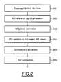
- FIG. 2illustrating a logic flow diagram showing an embodiment of a method of suppression of second order intermodulation.
- a part of a transmit radiofrequency signal S TXRF-REF generated by an up converter 6 of transmission means 1is injected into a mixer 9 of reception means 4.
- a second order intermodulation reference signal S IM2-REFis generated from a transmission baseband signal S TXBB-REF .
- a second order intermodulation poweris estimated from the second order intermodulation reference signal S IM2-REF and a radio transceiver output signal Output using adaptive filtering means.
- a subsequent step 204the code of a second order intermodulation intercept point tuner 24 is modified to find a lowest second order intermodulation power.
- An optimum second order intermodulation intercept point corresponding to the lowest second order intermodulation power foundis then extracted by the extracting means 23 (step 205), enabling therefore to calibrate the mixer with the code found for the IIP2 tuner 24 of the optimum second order intermodulation intercept point corresponding to the lowest power of second order intermodulation found.
- a step 206the second order intermodulation signal extracted from the radio transceiver output signal.
- Output using the adaptive filtering means included in the estimating means 22is subtracted to the reception output signal thanks to subtracting means 11.
Landscapes
- Engineering & Computer Science (AREA)
- Computer Networks & Wireless Communication (AREA)
- Signal Processing (AREA)
- Transceivers (AREA)
- Transmitters (AREA)
Description
- The present invention is related to wireless communication devices, and more particularly to a dynamic second order intercept point calibration enabling a second order interference reduction in direct conversion receivers.
- Direct conversion receiver (DCR) architecture is widely used in modern wireless communication systems essentially for its high integration level, resulting in a lower cost and smaller size. For example, DCR architecture such as zero intermediate frequency (ZIF) architecture is currently chosen for a radio receiver of third generation wideband code division multiple access (3G WCDMA) handset, or universal mobile telecommunication system (UMTS) handset.
- The main difficulties of direct conversion receivers are baseband co-located noises essentially linked to flicker noise, direct current offsets and second order intermodulation distortion (IM2), which all corrupt the desired signal and strongly degrade the receiver sensitivity. Flicker noise and direct current offsets can be mitigated by high pass filtering in wideband applications. Conversely, IM2 distortion still remains the most critical phenomena in such applications.
- Major IM2 contributions come from down conversion mixers, especially due to nonlinearities and mismatches in parts of its differential structure. They are essentially generated in the front-end mixers and occupy the same frequency band as the desired signal. IM2 power linked to any interferer depends on its power level and second order intercept point (IP2) level, which indicates a figure of merit for IM2 distortion compensation.
- For instance, in 3G WCDMA full duplex (FDD) receivers, the main difficulty is linked to IM2 distortion generated by the transmitter signal leakage. Moreover, 3G transceivers would need to get a new second order intermodulation intercept point (IIP2), as the 3G transceivers are getting more and more complex with, for instance, multi-band, multi-standard, multi-mode.
- The calibration problem is more critical in portable devices as calibration techniques need signal processing from a digital signal processor (DSP) chip, whose calculation power and availability is strongly limited.
- An automated calibration technique has been developed and offers a fast calibration but only when the mobile device is switched on. Moreover, temperature and frequency dependencies tend to decrease the performance level of the calibration point.
- For example, in a 3G WCDMA FDD operation mode, an external duplexer is needed to separate reception from transmission. A transmitter leakage due to limited finite duplexer isolation between transmission and reception appears into the input of the receiver. It is the main cause of second order intermodulation distortion. At the receiver's baseband, this corresponds to a squared version of the transmission signal envelope, and occupies twice the bandwidth of the transmission amplitude envelope, contributing thereby to the sensitivity degradation of the receiver.
- Document
US 2007/0184782 describes a transceiver having an adaptive second order intermodulation cancellation circuit, the transceiver comprising a transmitter and a receiver down-conversion circuit. The cancellation circuit comprises a second order intermodulation reconstruction circuit receiving a transmit signal from the transmitter and provides an approximate second order intermodulation signal that is substracted from a composite received signal from the receiver. - Document
WO 2008/089574 describes an automatic second order intermodulation intercept point calibration system comprising a receiver core, an IIP2 calibration circuit and a test signal generator. The IIP2 calibration circuit measures a value of the second order tone and generates a compensation or corrective signal to the specific circuit of receiver core. - Turning to the prior art,
US 2004 0 203 458 presents a method and apparatus to reduce second order interference in a communication device. It presents a technique to compensate the interference by signal processing. - However, this document presents a method to reduce intermodulation distortion caused by transmission leakage only.
- The dissertation ofKrzystof Duchêne, "Analysis and Cancellation Methods of Second Order Intermodulation Distortion in RFIC Downconversion Mixers", Erlangen 2007,", discloses a method and system for IIP2 calibration of a radio transceiver. An IM2 reference signal is generated from a transmit baseband signal. A cost function is calculated from the IM2 reference signal and the radio receiver output. The cost function is used to tune the downconverting mixer imbalance to the lowest IM2 power.
- Therefore, for instance, second order non-linearity linked to the adjacent channel in WCDMA is not removed by this method.
- Moreover, transceivers are becoming more and more complex and with it signal cohabitation is also becoming more complex.
- In view of the foregoing, it is hereby proposed to reduce general intermodulation distortion and to achieve a high second order intercept point requirement by dynamically calibrating the second order intercept point and even when the device is operating.
- In an aspect, it is proposed a method of calibration of a second order intermodulation intercept point of a radio transceiver.
- This method comprises the steps of:
- Generating a second order intermodulation (IM2) reference signal from a transmission baseband signal;
- Estimating a second order intermodulation power from the second order intermodulation reference signal and a radio transceiver output signal;
- Tuning the generated second order intermodulation intercept point to correspond to a lowest second order intermodulation power;
- Extracting an optimum second order intermodulation intercept point corresponding to the lowest second order intermodulation power found.
- According to a first feature, the second order intermodulation reference signal is preferably generated by an ideal square-law process of the transmission baseband signal.
- It is generally admitted that the second order intermodulation effect can be represented by a square-law process of the following type:

- Where |STXBB-REF| represents the magnitude of the time varying complex signal envelope of the transmission baseband signal, and α is a coefficient proportional to the second order intercept point.
- According to a second feature, the second order intermodulation power can advantageously be estimated with adaptive filtering means.
- For example, to estimate the second order intermodulation power, the adaptive filtering means extracts the second intermodulation signal included in the radio transceiver output signal by a convolution of the second order intermodulation reference signal with the radio transceiver output signal.
- In another aspect, it is proposed a method of suppression of second order intermodulation of reception means of a radio transceiver.
- According to one general feature of this method, it comprises the step of:
- Injecting a transmit radiofrequency signal from an up converter of a transmitter into a mixer of reception means;
- Generating a second order intermodulation (IM2) reference signal from a transmission baseband signal;
- Estimating a second order intermodulation power from the second order intermodulation reference signal and a radio transceiver output signal;
- Tuning the second order intermodulation intercept point to correspond to a lowest second order intermodulation power;
- Extracting an optimum second order intermodulation intercept point corresponding to the lowest second order intermodulation power;
- Subtracting the second order intermodulation signal extracted from the radio transceiver output signal to the reception putput signal.
- The transmit radiofrequency signal is used here as a test signal for the second order intermodulation power estimation.
- The complex envelope of the transmission leakage signal experiences some distortion, essentially through the amplifier and the duplexer's isolation. Therefore the transmission leakage signal can not be similar to the original transmit baseband signal, and strongly risks to degrade the estimation means performances based in a correlation level between these two complex envelopes. Moreover, the power of the transmission leakage signal varies in accordance with the WCDMA communication standard. This is a reason why, to overcome these restraints for the signal correlation of the estimator, a part of the transmission signal of constant power is injected to the mixer input of the reception means.
- The transmission leakage signal is uncorrelated from the transmission signal. As the quality of this uncorrelation impacts on the quality of the estimation, the transmission reference signal can be encoded if ever the transmission leakage signal is found to be correlated with the transmission signal.
- According to another feature, the steps of estimating the IM2 power, tuning the second order intermodulation intercept point, and extracting the optimum second order intermodulation intercept point are carried out in a closed loop.
- Using the transmit radiofrequency signal as a test signal for suppressing second order intermodulation and using a closed loop for optimum control enables to continuously adjust the calibration while the wireless communication device is working, compensating therefore the slow progressive degradation essentially due to low oscillation frequencies and temperature variations.
- Advantageously, the transmit radiofrequency signal injected into the mixer of the reception means can be modified according to the gain parameters of the radio transceiver.
- According to yet another feature, the reception means can include a direct conversion receiver.
- In a third aspect, it is proposed a system of calibration of a second order intermodulation intercept point of a radio transceiver.
- This system comprises generating means to generate a second order intermodulation reference signal from a transmission baseband signal, estimating means to estimate the second order intermodulation power from the second order intermodulation reference signal and a radio transceiver output signal, extracting means to extract an optimum second order intermodulation intercept point corresponding to a lowest second order intermodulation power and a second order intermodulation intercept point tuner (24) tuned to the optimum.
- Advantageously, the generating means includes means to process square-law of the transmission baseband signal.
- The estimating means may include adaptive filtering means.
- Advantageously, the adaptive filtering means comprises means to calculate a convolution of the second order intermodulation reference signal with the radio transceiver output signal.
- In a fourth aspect, it is proposed a system of suppression of second order intermodulation of reception means of a radio transceiver.
- The system includes injecting means to inject a transmit radiofrequency signal from an up converter of a transmitter into a mixer of reception means, generating means to generate a second order intermodulation reference signal from a transmission baseband signal, estimating means to estimate the second order intermodulation power from the second order intermodulation reference signal and a radio transceiver output signal, extracting means to extract an optimum second order intermodulation intercept point corresponding to a lowest second order intermodulation power found, subtraction means to subtract the second order intermodulation signal extracted from the radio transceiver output signal to the radio transceiver output signal.
- The system may further include a closed loop including the estimating means, the calibrating means and the second order intermodulation intercept point tuner.
- Advantageously, the injecting means can modify the transmit radiofrequency signal injected into the mixer of the reception means according to the gain parameters of the radio transceiver.
- The reception means can advantageously include a direct conversion receiver.
- Other advantages and characteristics of the invention will become apparent from the examination of the detailed description, being in no way limiting, and of the appended drawings on which:
Figure 1 presents a block diagram of a radio transceiver including an embodiment of a system of suppression of second order intermodulation;Figure 2 is a logic flow diagram that illustrates an embodiment of a method of suppression of second order intermodulation.Figure 1 presents a block diagram of a wireless communication device such as a radio transceiver including an embodiment of a system of suppression of second order intermodulation.- The present system is equally applicable to analog and digital signals. Signals may be in digital or analog form and in some cases can be real or complex, i.e. separate signal components representing the real and imaginary parts. The digital, analog or complex nature of a signal has no impact on the general processing concepts described herein.
- The radio transceiver includes transmitting means 1 able to transmit a radio frequency signal to another radio transceiver through a
duplexer 2 coupled to anantenna 3, and reception means 4 able to receive through theduplexer 2 coupled to the antenna 3 a radiofrequency signal emitted by another radio transceiver. - Transmit data are provided to a
baseband generator 5, such as a digital signal processor. The baseband generator produces the actual complex modulation envelope signal for the transmitting means 1, locally available as the transmission baseband signal STXBB-REF in a direct conversion radio, for example. The transmit baseband signal modulates the transmit carrier through a frequency upconverter 6 to produce a transmit radio frequency signal STXRF-REF. The transmit radio frequency signal is amplified by apower amplifier 7, and is injected intoduplexer 2 and sent out by means of theantenna 3. - At the transmission side, some of the transmit radio frequency signal will find its way to the reception means 4 input as interference, due to finite isolation between separate antennas or the use of a single antenna for both transmitting means 1 and the affected reception means 4. This transmission leakage signal will lead to the formation of second order intermodulation in the signal received by the reception means 4 at the reception side.
- The transmission leakage signal passes through and is modified by the front end of the reception means 4, including a
low noise amplifier 8. At this point, the complex envelope of the transmission leakage signal has experienced some distortion, both non-linear and linear. - After passing through the
low noise amplifier 8, the transmission leakage signal is injected into amixer 9. The signal is then filtered using filtering means 10 to filter and amplify the signal which is passing there through. - In this embodiment, a second order intermodulation intercept point (IIP2)
calibration system 20 is implemented to the radio transceiver. - The
IIP2 calibration system 20 includes generating means 21 to generate a second order intermodulation reference signal SIM2-REF from a transmission baseband signal STXBB-REF, estimating means 22 to estimate the second order intermodulation power from the second order intermodulation reference signal SIM2-REF and a radio transceiver output signal, a second order intermodulationintercept point tuner 24, and extractingmeans 23 to extract an optimum second order intermodulation intercept point corresponding to a lowest second order intermodulation power. - Generating means 21 generates a second order intermodulation reference signal SIM2-REF from the transmission baseband signal STXBB-REF. The second order intermodulation reference signal SIM2-REF is generated by an ideal square-law process of the transmission baseband signal STXBB-REF.
- It is theoretically admitted that the second order intermodulation effect can be represented by an ideal square-law process of the following type:

Where |STXBB-REF| represents the magnitude of the time varying complex signal envelope of the transmission baseband signal, and α is a coefficient proportional to the second order intercept point. - The second order intermodulation reference signal SIM2-REF generated by the generating means 21 is injected into estimating means 22 which also receives in input a radio transceiver output signalOutput.
- To estimate the second order intermodulation power of the second order intermodulation signal comprised in the radio transceiver output signal, the estimating means 22 uses adaptive filtering means. For instance, an adaptive transversal filter using a least mean squared adaptive control algorithm could be used in this embodiment.
- The adaptive filtering means extracts the second order intermodulation signal included in the radio transceiver output signal by convoluting the second order intermodulation reference signal SIM2-REF with the radio transceiver output signalOutput, and adjusting its filtering parameters applied to the second order intermodulation reference signal SIM2-REF through an adaptive control algorithm.
- Having extracted the second order intermodulation signal included in the radio transceiver output signalOutput using the adaptive means, the estimating means 22 thus estimate the power of the second order intermodulation signal.
- The power of the second order intermodulation signal, and in particular the power of the low frequency IM2 signal, is linked to the second order intermodulation intercept point by the following equation:

Where: - PIM2 represents the power of the second order intermodulation signal,
- PTXRF-REF represents the power of the transmit radiofrequency reference signal,
- IIP2 represents the second order intermodulation intercept point, and
- KTX is a corrective factor which takes into account that the transmit radiofrequency reference signal STXRF-REF is not a two tones but a bandwidth signal.
- Therefore, the real second order intermodulation intercept point can be extracted from the estimation of the power of the second order intermodulation by the extracting
means 23. With the real IIP2 extracted, the extracting means 23 starts running the calibration of the mixer in collaboration with the second order intermodulationintercept point tuner 24 using an algorithm intended to change the code of theIIP2 tuner 24 and to measure whether the second order intermodulation power has risen or has been lowered. Once the IIP2 tuner code corresponding to the lowest IM2 power has been found, it is considered that the IIP2 with the highest level has been found. This IIP2 is thus extracted. Meanwhile, theIIP2 tuner 24 keeps the code corresponding to the lowest IM2 power, optimising therefore the calibration of themixer 9 formed by theIIP2 tuner 24 which can be used as an impedance network coupled with a mixer to stabilize the asymmetry present in themixer 9 and to cause the second order intermodulation. - To calibrate the second order intermodulation while the mobile is working and therefore suppress the second intermodulation present in the output signal with the best efficiency, a calibration of the
mixer 9 and an estimation of the second order intermodulation is made with a transmit radiofrequency reference signal STXRF-REF as a test signal. - A part of the transmit radiofrequency reference signal STXRF-REF generated by the up
converter 6 of the transmission means 1 is injected thanks to injecting means 25 into themixer 9 of the reception means which is in this embodiment a direct conversion receiver. The transmit radiofrequency reference signal STXRF-REF is used here as a test signal for the second order intermodulation power estimation. - The complex envelope of the transmission leakage signal experiences some large amplitude and phase distortion, essentially through the amplifier and the duplexer's isolation. The transmission signal generated by the transmission means 1 operates in a frequency bandwidth which the
duplexer 2 is supposed to reject, and prevent the transmission signal from passing through towards the reception means 4. It is therefore a frequency window in the slope of the isolation response, and thus the isolation is strongly dependant on the frequency. Therefore, the transmission leakage signal can not be similar to the original transmit baseband signal, and strongly risks to degrade the estimation means performances based in a correlation level between these two complex envelopes. - Moreover, the power of the transmission leakage signal varies in accordance with the control by the base station as defined in the WCDMA communication standard. This is a reason why, to overcome these restraints for the signal correlation of the estimator, a part of the transmission radiofrequency signal of constant power is injected to the
mixer 9 input of the reception means 4 through injection means 25. - For example, when a mobile phone comprising such a radio transceiver is very close to the base station, a low power of transmission will be requested, and this base station may transmit a high power level towards other mobile phones in the neighbouring channels. Using a transmit radiofrequency reference signal STXRF-REF as an input of the
mixer 9 will create a significant second order intermodulation, and thus enable an accurate second order intercept point calibration, that will cancel the second order intermodulation interference signals generated by the base station transmission signals in the neighbouring channels. - This is major advantage as these second order intermodulation interference will be output within the reception channel after the down mixer. In many practical designs of receiver chains, a switchable operating current of a mixer is implemented; an adjustment of the gain of this injection can be controlled depending on this mixer operation point, that sets an optimum power level of the test signal high enough for the accuracy of the calibration process, and low enough to cancel the second order intermodulation down to a level well below the desired received signal after the convergence of the calibration process.
- The transmission leakage signal is uncorrelated from the transmission signal. As the quality of this uncorrelation impacts on the quality of the estimation, the transmission radiofrequency reference signal STXRF-REF can be encoded if ever the transmission leakage signal is found to be correlated with the transmission signal.
- Using a part of the transmit radiofrequency reference signal instead of the transmission leakage signal as a test signal, avoids from having to add a filter before the reception means input.
- Thus, the radio transceiver output signalOutput is correlated with the second order intermodulation reference signal SIM2-REF enabling an efficient estimation of the power of the second order intermodulation signal included in the radio transceiver output signalOutput.
- After extraction of the second order intermodulation signal from the radio transceiver output signalOutput using the adaptive filtering means, the signal is subtracted from the output signal of the reception means 4 by means of the subtracting means 11. The
mixer 9 having been calibrated byIIP2 tuner 24, the lowest second order intermodulation power can thus be found. - Reference is now made to
Figure 2 illustrating a logic flow diagram showing an embodiment of a method of suppression of second order intermodulation. - In a
first step 201, a part of a transmit radiofrequency signal STXRF-REF generated by an upconverter 6 of transmission means 1 is injected into amixer 9 of reception means 4. In a followingstep 202, a second order intermodulation reference signal SIM2-REF is generated from a transmission baseband signal STXBB-REF. - Then, in a
next step 203, a second order intermodulation power is estimated from the second order intermodulation reference signal SIM2-REF and a radio transceiver output signalOutput using adaptive filtering means. - In a
subsequent step 204, the code of a second order intermodulationintercept point tuner 24 is modified to find a lowest second order intermodulation power. - An optimum second order intermodulation intercept point corresponding to the lowest second order intermodulation power found is then extracted by the extracting means 23 (step 205), enabling therefore to calibrate the mixer with the code found for the
IIP2 tuner 24 of the optimum second order intermodulation intercept point corresponding to the lowest power of second order intermodulation found. - Finally, in a
step 206, the second order intermodulation signal extracted from the radio transceiver output signal.Output using the adaptive filtering means included in the estimating means 22 is subtracted to the reception output signal thanks to subtractingmeans 11.


Claims (16)
- Method of calibration of a second order intermodulation intercept point (IIP2) of a radio transceiver, comprising the steps of:- Generating a second order intermodulation (IM2) reference signal (SIM2-REF) from a transmission baseband signal (STXBB-REF);- Estimating a second order intermodulation power from the second order intermodulation reference signal (SIM2-REF) and a radio transceiver output signal (Output);- Tuning a second order intermodulation intercept point tuner to correspond to a lowest second order intermodulation power;- Extracting an optimum second order intermodulation intercept point corresponding to the lowest second order intermodulation power.
- Method as claimed in claim 1, wherein the second order intermodulation reference signal (SIM2-REF) is generated by square-law process of the transmission baseband signal (STXBB-REF).
- Method as claimed in claim 1 or 2, wherein the second order intermodulation power is estimated with adaptive filtering means.
- Method as claimed in claim 3, wherein, to estimate the second order intermodulation power, the adaptive filtering means extracts the second order intermodulation signal included in the radio transceiver output signal (Output) by a convolution of the second order intermodulation reference signal (SIM2-REF) with the radio transceiver output signal (Output).
- Method of suppression of second order intermodulation of reception means (4) of a radio transceiver, comprising the step of:- Injecting a transmit radiofrequency signal (STXRF-REF) from an up converter (6) of transmission means (1) into a mixer (9) of reception means (4);- Generating a second order intermodulation reference signal (SIM2-REF) from a transmission baseband signal (STXBB-REF);- Estimating a second order intermodulation power from the second order intermodulation reference signal (SIM2-REF) and a radio transceiver output signal (Output);- Tuning a second order intermodulation intercept point corresponding to a lowest second order intermodulation power;- Extracting an optimum second order intermodulation intercept point corresponding to the lowest second order intermodulation power found;- Subtracting a second order intermodulation signal extracted from the radio transceiver output signal (Output) to the reception output signal.
- Method as claimed in claim 5, wherein the steps of estimating the second order intermodulation power, modifying the tuner (24), and extracting the optimum second order intermodulation intercept point are carried out in a closed loop.
- Method as claimed in claim 5 or 6, wherein the transmit radiofrequency signal (STXRF-REF) injected into the mixer (9) of the reception means (4) can be modified according to the gain parameters of the radio transceiver.
- Method as claimed in claim 5 to 7, wherein the reception means (4) includes a direct conversion receiver.
- System of calibration of a second order intermodulation intercept point (IIP2) of a radio transceiver, comprising generating means (21) to generate a second order intermodulation reference signal (SIM2-REF) from a transmission baseband signal (STXBB-REF), estimating means (22) to estimate the second order intermodulation power from the second order intermodulation reference signal (SIM2-REF) and a radio transceiver output signal (Output), extracting means (23) to extract an optimum second order intermodulation intercept point corresponding to a lowest second order intermodulation power and a second order intermodulation intercept point tuner (24) tuned to said optimum.
- System as claimed in claim 9, wherein the generating means (21) includes means to process square-law of the transmission baseband signal.
- System as claimed in claim 9 or 10, wherein the estimating means (22) includes adaptive filtering means.
- System as claimed in claim 11, wherein the adaptive filtering means comprises means to calculate a convolution of the second order intermodulation reference (SIM2-REF) signal with the radio transceiver output signal (Output).
- System of suppression of second order intermodulation of reception means (4) of a radio transceiver, comprising injecting means (25) to inject a transmit radiofrequency signal (STXRF-REF) from an up converter (6) of transmission means (1) into a mixer (9) of reception means (4), generating means (21) to generate a second order intermodulation reference signal (SIM2-REF) from a transmission baseband signal (STXBB-REF), estimating means (22) to estimate the second order intermodulation power from the second order intermodulation reference signal (SIM2-REF) and a radio transceiver output signal (Output), extracting means (23) to extract an optimum second order intermodulation intercept point corresponding to a lowest second order intermodulation power, subtraction means (11) to subtract a second order intermodulation signal extracted from the radio transceiver output signal (Output) to the reception output signal.
- System as claimed in claim 13, wherein it includes a closed loop including said estimating means (22), said extracting means (23) and a second order intermodulation intercept point tuner (24).
- System as claimed in claim 13 or 14, wherein the injecting means (25) can modify the transmit radiofrequency signal (STXRF-REF) injected into the mixer (9) of the reception means (4) according to the gain parameters of the radio transceiver.
- System as claimed in claim 13 to 15, wherein the reception means includes a direct conversion receiver.
Priority Applications (6)
| Application Number | Priority Date | Filing Date | Title |
|---|---|---|---|
| ES08305928TES2406705T3 (en) | 2008-12-12 | 2008-12-12 | Method and system of calibration of a second order intermodulation interception point of a radio transceiver |
| EP08305928AEP2197119B1 (en) | 2008-12-12 | 2008-12-12 | Method and system of calibration of a second order intermodulation intercept point of a radio transceiver |
| CN200980150039.9ACN102246423B (en) | 2008-12-12 | 2009-11-25 | Method and system of calibration of a second order intermodulation intercept point of a radio transceiver |
| PCT/EP2009/065811WO2010066579A1 (en) | 2008-12-12 | 2009-11-25 | Method and system of calibration of a second order intermodulation intercept point of a radio transceiver |
| KR1020117013352AKR101602520B1 (en) | 2008-12-12 | 2009-11-25 | Method and system of calibration of a second order intermodulation intercept point of a radio transceiver |
| US13/139,128US9178559B2 (en) | 2008-12-12 | 2009-11-25 | Method and system of calibration of a second order intermodulation intercept point of a radio transceiver |
Applications Claiming Priority (1)
| Application Number | Priority Date | Filing Date | Title |
|---|---|---|---|
| EP08305928AEP2197119B1 (en) | 2008-12-12 | 2008-12-12 | Method and system of calibration of a second order intermodulation intercept point of a radio transceiver |
Publications (2)
| Publication Number | Publication Date |
|---|---|
| EP2197119A1 EP2197119A1 (en) | 2010-06-16 |
| EP2197119B1true EP2197119B1 (en) | 2013-02-13 |
Family
ID=40578402
Family Applications (1)
| Application Number | Title | Priority Date | Filing Date |
|---|---|---|---|
| EP08305928ANot-in-forceEP2197119B1 (en) | 2008-12-12 | 2008-12-12 | Method and system of calibration of a second order intermodulation intercept point of a radio transceiver |
Country Status (6)
| Country | Link |
|---|---|
| US (1) | US9178559B2 (en) |
| EP (1) | EP2197119B1 (en) |
| KR (1) | KR101602520B1 (en) |
| CN (1) | CN102246423B (en) |
| ES (1) | ES2406705T3 (en) |
| WO (1) | WO2010066579A1 (en) |
Cited By (2)
| Publication number | Priority date | Publication date | Assignee | Title |
|---|---|---|---|---|
| US9325360B2 (en) | 2010-09-28 | 2016-04-26 | Qualcomm Incorporated | Reducing non-linearities in a differential receiver path prior to a mixer using calibration |
| US11804867B2 (en) | 2017-10-03 | 2023-10-31 | Surewave Technology Limited | Signal processing systems and methods |
Families Citing this family (21)
| Publication number | Priority date | Publication date | Assignee | Title |
|---|---|---|---|---|
| US8634793B2 (en) | 2010-05-10 | 2014-01-21 | Csr Technology Inc. | IP2 calibration measurement and signal generation |
| US8805312B2 (en) | 2011-04-06 | 2014-08-12 | Texas Instruments Incorporated | Methods, circuits, systems and apparatus providing audio sensitivity enhancement in a wireless receiver, power management and other performances |
| GB2502279B (en) | 2012-05-21 | 2014-07-09 | Aceaxis Ltd | Reduction of intermodulation products |
| EP2709287A1 (en)* | 2012-09-17 | 2014-03-19 | ST-Ericsson SA | On-chip stimulus generation for test and calibration of nfc reader receivers |
| WO2014078455A1 (en)* | 2012-11-13 | 2014-05-22 | Spectra7 Microsystems Ltd | Method and system for signal dynamic range improvement for frequency-division duplex communication systems |
| US8917792B2 (en)* | 2012-12-12 | 2014-12-23 | Motorola Mobility Llc | Method and apparatus for the cancellation of intermodulation and harmonic distortion in a baseband receiver |
| US8811538B1 (en) | 2013-03-15 | 2014-08-19 | Blackberry Limited | IQ error correction |
| US9197279B2 (en) | 2013-03-15 | 2015-11-24 | Blackberry Limited | Estimation and reduction of second order distortion in real time |
| US8942656B2 (en) | 2013-03-15 | 2015-01-27 | Blackberry Limited | Reduction of second order distortion in real time |
| US8983486B2 (en) | 2013-03-15 | 2015-03-17 | Blackberry Limited | Statistical weighting and adjustment of state variables in a radio |
| EP2779510B1 (en) | 2013-03-15 | 2018-10-31 | BlackBerry Limited | Statistical weighting and adjustment of state variables in a radio |
| US9252892B2 (en)* | 2013-05-30 | 2016-02-02 | Ncr Corporation | Device and method for active reduction of radio frequency noise |
| US9444559B2 (en) | 2013-06-03 | 2016-09-13 | Futurewei Technologies, Inc. | Second order intercept point (IP2) calibration for wireless receivers |
| US9461756B2 (en) | 2014-03-06 | 2016-10-04 | Samsung Electronics Co., Ltd | Calibration apparatus and method of terminal in wireless communication system |
| GB2544753B (en)* | 2015-11-24 | 2021-12-08 | Trw Ltd | Transceiver Circuits |
| US9712198B1 (en) | 2016-03-18 | 2017-07-18 | Samsung Electronics Co., Ltd | Apparatus and method for providing background real-time second order input intercept point calibration |
| EP3264620A1 (en)* | 2016-07-01 | 2018-01-03 | Intel IP Corporation | Methods and transceivers for reducing a distortion component within a baseband receive signal |
| CN106301516B (en) | 2016-08-08 | 2020-07-21 | 华为技术有限公司 | Diversity receiver and terminal |
| KR102573878B1 (en)* | 2017-01-17 | 2023-09-01 | 삼성전자주식회사 | An apparatus for processing signal in a wireless communication system and a method thereof |
| KR102447804B1 (en) | 2017-09-05 | 2022-09-27 | 삼성전자주식회사 | Electronic device comprising a wireless communication system for processing a transmitted signal or a received signal |
| CN113439391B (en)* | 2019-02-28 | 2022-11-22 | 华为技术有限公司 | Method and device for correcting intermodulation distortion signal of receiver |
Family Cites Families (19)
| Publication number | Priority date | Publication date | Assignee | Title |
|---|---|---|---|---|
| US6591091B1 (en)* | 1998-11-12 | 2003-07-08 | Broadcom Corporation | System and method for coarse/fine PLL adjustment |
| US6525609B1 (en)* | 1998-11-12 | 2003-02-25 | Broadcom Corporation | Large gain range, high linearity, low noise MOS VGA |
| AU5299600A (en)* | 1999-05-26 | 2000-12-12 | Broadcom Corporation | Integrated vco |
| US7106388B2 (en)* | 1999-12-15 | 2006-09-12 | Broadcom Corporation | Digital IF demodulator for video applications |
| US6704349B1 (en) | 2000-01-18 | 2004-03-09 | Ditrans Corporation | Method and apparatus for canceling a transmit signal spectrum in a receiver bandwidth |
| US6509796B2 (en)* | 2000-02-15 | 2003-01-21 | Broadcom Corporation | Variable transconductance variable gain amplifier utilizing a degenerated differential pair |
| CN1280981C (en)* | 2001-11-16 | 2006-10-18 | 松下电器产业株式会社 | Power amplifier, power amplifying method and radio communication device |
| US7299021B2 (en) | 2001-12-28 | 2007-11-20 | Nokia Corporation | Method and apparatus for scaling the dynamic range of a receiver for continuously optimizing performance versus power consumption |
| US7203472B2 (en) | 2002-03-15 | 2007-04-10 | Nokia Corporation | Method and apparatus providing calibration technique for RF performance tuning |
| US7043208B2 (en) | 2002-10-15 | 2006-05-09 | Motorola, Inc. | Method and apparatus to reduce interference in a communication device |
| CN1707961B (en)* | 2004-06-09 | 2012-07-04 | 天津滨海鼎芯科技有限公司 | Zero intermediate frequency radio receiver second-order inter-modulation automatic correcting circuit |
| ATE394830T1 (en)* | 2004-07-06 | 2008-05-15 | Acp Advanced Circuit Pursuit A | SYMMETRIC MIXER WITH FETS |
| US7483678B2 (en)* | 2005-09-27 | 2009-01-27 | Skyworks Solutions, Inc. | Single chip GSM/EDGE transceiver architecture with closed loop power control |
| US8170487B2 (en)* | 2006-02-03 | 2012-05-01 | Qualcomm, Incorporated | Baseband transmitter self-jamming and intermodulation cancellation device |
| JP4682335B2 (en)* | 2006-03-30 | 2011-05-11 | エスティー‐エリクソン、ソシエテ、アノニム | Self-calibrating mixer |
| US7742747B2 (en) | 2007-01-25 | 2010-06-22 | Icera Canada ULC | Automatic IIP2 calibration architecture |
| US8010074B2 (en)* | 2008-02-08 | 2011-08-30 | Freescale Semiconductor, Inc. | Mixer circuits for second order intercept point calibration |
| US8126036B2 (en)* | 2008-06-21 | 2012-02-28 | Vyycore Corporation | Predistortion and post-distortion correction of both a receiver and transmitter during calibration |
| US8060043B2 (en)* | 2008-10-09 | 2011-11-15 | Freescale Semiconductor | Adaptive IIP2 calibration |
- 2008
- 2008-12-12EPEP08305928Apatent/EP2197119B1/ennot_activeNot-in-force
- 2008-12-12ESES08305928Tpatent/ES2406705T3/enactiveActive
- 2009
- 2009-11-25USUS13/139,128patent/US9178559B2/ennot_activeExpired - Fee Related
- 2009-11-25KRKR1020117013352Apatent/KR101602520B1/ennot_activeExpired - Fee Related
- 2009-11-25CNCN200980150039.9Apatent/CN102246423B/ennot_activeExpired - Fee Related
- 2009-11-25WOPCT/EP2009/065811patent/WO2010066579A1/enactiveApplication Filing
Non-Patent Citations (1)
| Title |
|---|
| DUFRÊNE K: "Analysis and Cancellation Methods of Second Order Intermodulation Distortion in RFIC Downconversion Mixers", part chapter 5 2007, Erlangen, article "IMD2 Cancellation Methods"* |
Cited By (3)
| Publication number | Priority date | Publication date | Assignee | Title |
|---|---|---|---|---|
| US9325360B2 (en) | 2010-09-28 | 2016-04-26 | Qualcomm Incorporated | Reducing non-linearities in a differential receiver path prior to a mixer using calibration |
| US11804867B2 (en) | 2017-10-03 | 2023-10-31 | Surewave Technology Limited | Signal processing systems and methods |
| US12255676B2 (en) | 2017-10-03 | 2025-03-18 | Surewave Technology Limited | Signal processing systems and methods |
Also Published As
| Publication number | Publication date |
|---|---|
| CN102246423A (en) | 2011-11-16 |
| KR20110104489A (en) | 2011-09-22 |
| US9178559B2 (en) | 2015-11-03 |
| CN102246423B (en) | 2014-02-26 |
| KR101602520B1 (en) | 2016-03-10 |
| US20110299575A1 (en) | 2011-12-08 |
| WO2010066579A1 (en) | 2010-06-17 |
| ES2406705T3 (en) | 2013-06-07 |
| EP2197119A1 (en) | 2010-06-16 |
Similar Documents
| Publication | Publication Date | Title |
|---|---|---|
| EP2197119B1 (en) | Method and system of calibration of a second order intermodulation intercept point of a radio transceiver | |
| US7043208B2 (en) | Method and apparatus to reduce interference in a communication device | |
| CN101521520B (en) | Full division duplex system and leakage elimination method | |
| US8150350B2 (en) | Adaptive IIP2 calibration | |
| US8565681B2 (en) | Systems, methods, and apparatuses for reducing interference at the front-end of a communications receiving device | |
| EP3285404B1 (en) | Digital-centric full-duplex architecture | |
| US9647705B2 (en) | Digital self-interference residual cancellation | |
| US8503926B2 (en) | IQ imbalance compensation in interference cancellation repeater using a zero-IF radio architecture | |
| CN101502007B (en) | Intermodulation Distortion Detection and Mitigation | |
| US7916671B1 (en) | Echo cancellation for duplex radios | |
| US20110256857A1 (en) | Systems and Methods for Improving Antenna Isolation Using Signal Cancellation | |
| EP2474099B1 (en) | Radio environment scanner | |
| CN102739268A (en) | Transmitter and Compensation Method | |
| US20200244294A1 (en) | Adjusting parameters of a receiver system | |
| JP2004521534A (en) | Direct conversion digital domain control | |
| Schacherbauer et al. | A flexible multiband frontend for software radios using high IF and active interference cancellation | |
| US11251880B2 (en) | CA power measurement | |
| KR102159973B1 (en) | Apparatus and method for second order input intercept point calibration | |
| Williamson et al. | Performance Analysis of Adaptive Wideband Duplexer | |
| WO2010025568A1 (en) | A method and system for dynamic signal to noise ratio adjustment in a transceiver |
Legal Events
| Date | Code | Title | Description |
|---|---|---|---|
| PUAI | Public reference made under article 153(3) epc to a published international application that has entered the european phase | Free format text:ORIGINAL CODE: 0009012 | |
| AK | Designated contracting states | Kind code of ref document:A1 Designated state(s):AT BE BG CH CY CZ DE DK EE ES FI FR GB GR HR HU IE IS IT LI LT LU LV MC MT NL NO PL PT RO SE SI SK TR | |
| AX | Request for extension of the european patent | Extension state:AL BA MK RS | |
| 17P | Request for examination filed | Effective date:20101203 | |
| 17Q | First examination report despatched | Effective date:20101223 | |
| AKX | Designation fees paid | Designated state(s):AT BE BG CH CY CZ DE DK EE ES FI FR GB GR HR HU IE IS IT LI LT LU LV MC MT NL NO PL PT RO SE SI SK TR | |
| GRAP | Despatch of communication of intention to grant a patent | Free format text:ORIGINAL CODE: EPIDOSNIGR1 | |
| GRAS | Grant fee paid | Free format text:ORIGINAL CODE: EPIDOSNIGR3 | |
| RAP1 | Party data changed (applicant data changed or rights of an application transferred) | Owner name:ST-ERICSSON SA | |
| GRAA | (expected) grant | Free format text:ORIGINAL CODE: 0009210 | |
| AK | Designated contracting states | Kind code of ref document:B1 Designated state(s):AT BE BG CH CY CZ DE DK EE ES FI FR GB GR HR HU IE IS IT LI LT LU LV MC MT NL NO PL PT RO SE SI SK TR | |
| REG | Reference to a national code | Ref country code:GB Ref legal event code:FG4D | |
| REG | Reference to a national code | Ref country code:AT Ref legal event code:REF Ref document number:596952 Country of ref document:AT Kind code of ref document:T Effective date:20130215 | |
| REG | Reference to a national code | Ref country code:IE Ref legal event code:FG4D | |
| REG | Reference to a national code | Ref country code:DE Ref legal event code:R096 Ref document number:602008022089 Country of ref document:DE Effective date:20130411 | |
| REG | Reference to a national code | Ref country code:ES Ref legal event code:FG2A Ref document number:2406705 Country of ref document:ES Kind code of ref document:T3 Effective date:20130607 | |
| REG | Reference to a national code | Ref country code:NL Ref legal event code:T3 | |
| REG | Reference to a national code | Ref country code:AT Ref legal event code:MK05 Ref document number:596952 Country of ref document:AT Kind code of ref document:T Effective date:20130213 | |
| REG | Reference to a national code | Ref country code:LT Ref legal event code:MG4D | |
| PG25 | Lapsed in a contracting state [announced via postgrant information from national office to epo] | Ref country code:BG Free format text:LAPSE BECAUSE OF FAILURE TO SUBMIT A TRANSLATION OF THE DESCRIPTION OR TO PAY THE FEE WITHIN THE PRESCRIBED TIME-LIMIT Effective date:20130513 Ref country code:AT Free format text:LAPSE BECAUSE OF FAILURE TO SUBMIT A TRANSLATION OF THE DESCRIPTION OR TO PAY THE FEE WITHIN THE PRESCRIBED TIME-LIMIT Effective date:20130213 Ref country code:SE Free format text:LAPSE BECAUSE OF FAILURE TO SUBMIT A TRANSLATION OF THE DESCRIPTION OR TO PAY THE FEE WITHIN THE PRESCRIBED TIME-LIMIT Effective date:20130213 Ref country code:LT Free format text:LAPSE BECAUSE OF FAILURE TO SUBMIT A TRANSLATION OF THE DESCRIPTION OR TO PAY THE FEE WITHIN THE PRESCRIBED TIME-LIMIT Effective date:20130213 Ref country code:IS Free format text:LAPSE BECAUSE OF FAILURE TO SUBMIT A TRANSLATION OF THE DESCRIPTION OR TO PAY THE FEE WITHIN THE PRESCRIBED TIME-LIMIT Effective date:20130613 Ref country code:NO Free format text:LAPSE BECAUSE OF FAILURE TO SUBMIT A TRANSLATION OF THE DESCRIPTION OR TO PAY THE FEE WITHIN THE PRESCRIBED TIME-LIMIT Effective date:20130513 | |
| PG25 | Lapsed in a contracting state [announced via postgrant information from national office to epo] | Ref country code:SI Free format text:LAPSE BECAUSE OF FAILURE TO SUBMIT A TRANSLATION OF THE DESCRIPTION OR TO PAY THE FEE WITHIN THE PRESCRIBED TIME-LIMIT Effective date:20130213 Ref country code:BE Free format text:LAPSE BECAUSE OF FAILURE TO SUBMIT A TRANSLATION OF THE DESCRIPTION OR TO PAY THE FEE WITHIN THE PRESCRIBED TIME-LIMIT Effective date:20130213 Ref country code:GR Free format text:LAPSE BECAUSE OF FAILURE TO SUBMIT A TRANSLATION OF THE DESCRIPTION OR TO PAY THE FEE WITHIN THE PRESCRIBED TIME-LIMIT Effective date:20130514 Ref country code:PL Free format text:LAPSE BECAUSE OF FAILURE TO SUBMIT A TRANSLATION OF THE DESCRIPTION OR TO PAY THE FEE WITHIN THE PRESCRIBED TIME-LIMIT Effective date:20130213 Ref country code:FI Free format text:LAPSE BECAUSE OF FAILURE TO SUBMIT A TRANSLATION OF THE DESCRIPTION OR TO PAY THE FEE WITHIN THE PRESCRIBED TIME-LIMIT Effective date:20130213 Ref country code:PT Free format text:LAPSE BECAUSE OF FAILURE TO SUBMIT A TRANSLATION OF THE DESCRIPTION OR TO PAY THE FEE WITHIN THE PRESCRIBED TIME-LIMIT Effective date:20130613 Ref country code:LV Free format text:LAPSE BECAUSE OF FAILURE TO SUBMIT A TRANSLATION OF THE DESCRIPTION OR TO PAY THE FEE WITHIN THE PRESCRIBED TIME-LIMIT Effective date:20130213 | |
| PG25 | Lapsed in a contracting state [announced via postgrant information from national office to epo] | Ref country code:HR Free format text:LAPSE BECAUSE OF FAILURE TO SUBMIT A TRANSLATION OF THE DESCRIPTION OR TO PAY THE FEE WITHIN THE PRESCRIBED TIME-LIMIT Effective date:20130213 | |
| PG25 | Lapsed in a contracting state [announced via postgrant information from national office to epo] | Ref country code:SK Free format text:LAPSE BECAUSE OF FAILURE TO SUBMIT A TRANSLATION OF THE DESCRIPTION OR TO PAY THE FEE WITHIN THE PRESCRIBED TIME-LIMIT Effective date:20130213 Ref country code:EE Free format text:LAPSE BECAUSE OF FAILURE TO SUBMIT A TRANSLATION OF THE DESCRIPTION OR TO PAY THE FEE WITHIN THE PRESCRIBED TIME-LIMIT Effective date:20130213 Ref country code:RO Free format text:LAPSE BECAUSE OF FAILURE TO SUBMIT A TRANSLATION OF THE DESCRIPTION OR TO PAY THE FEE WITHIN THE PRESCRIBED TIME-LIMIT Effective date:20130213 Ref country code:CZ Free format text:LAPSE BECAUSE OF FAILURE TO SUBMIT A TRANSLATION OF THE DESCRIPTION OR TO PAY THE FEE WITHIN THE PRESCRIBED TIME-LIMIT Effective date:20130213 Ref country code:DK Free format text:LAPSE BECAUSE OF FAILURE TO SUBMIT A TRANSLATION OF THE DESCRIPTION OR TO PAY THE FEE WITHIN THE PRESCRIBED TIME-LIMIT Effective date:20130213 | |
| PLBE | No opposition filed within time limit | Free format text:ORIGINAL CODE: 0009261 | |
| STAA | Information on the status of an ep patent application or granted ep patent | Free format text:STATUS: NO OPPOSITION FILED WITHIN TIME LIMIT | |
| PG25 | Lapsed in a contracting state [announced via postgrant information from national office to epo] | Ref country code:IT Free format text:LAPSE BECAUSE OF FAILURE TO SUBMIT A TRANSLATION OF THE DESCRIPTION OR TO PAY THE FEE WITHIN THE PRESCRIBED TIME-LIMIT Effective date:20130213 | |
| 26N | No opposition filed | Effective date:20131114 | |
| REG | Reference to a national code | Ref country code:DE Ref legal event code:R097 Ref document number:602008022089 Country of ref document:DE Effective date:20131114 | |
| REG | Reference to a national code | Ref country code:CH Ref legal event code:PL | |
| PG25 | Lapsed in a contracting state [announced via postgrant information from national office to epo] | Ref country code:LU Free format text:LAPSE BECAUSE OF FAILURE TO SUBMIT A TRANSLATION OF THE DESCRIPTION OR TO PAY THE FEE WITHIN THE PRESCRIBED TIME-LIMIT Effective date:20131212 Ref country code:MC Free format text:LAPSE BECAUSE OF FAILURE TO SUBMIT A TRANSLATION OF THE DESCRIPTION OR TO PAY THE FEE WITHIN THE PRESCRIBED TIME-LIMIT Effective date:20130213 | |
| REG | Reference to a national code | Ref country code:IE Ref legal event code:MM4A | |
| REG | Reference to a national code | Ref country code:FR Ref legal event code:ST Effective date:20140829 | |
| PG25 | Lapsed in a contracting state [announced via postgrant information from national office to epo] | Ref country code:CH Free format text:LAPSE BECAUSE OF NON-PAYMENT OF DUE FEES Effective date:20131231 Ref country code:LI Free format text:LAPSE BECAUSE OF NON-PAYMENT OF DUE FEES Effective date:20131231 Ref country code:IE Free format text:LAPSE BECAUSE OF NON-PAYMENT OF DUE FEES Effective date:20131212 | |
| PG25 | Lapsed in a contracting state [announced via postgrant information from national office to epo] | Ref country code:FR Free format text:LAPSE BECAUSE OF NON-PAYMENT OF DUE FEES Effective date:20131231 | |
| PG25 | Lapsed in a contracting state [announced via postgrant information from national office to epo] | Ref country code:TR Free format text:LAPSE BECAUSE OF FAILURE TO SUBMIT A TRANSLATION OF THE DESCRIPTION OR TO PAY THE FEE WITHIN THE PRESCRIBED TIME-LIMIT Effective date:20130213 Ref country code:CY Free format text:LAPSE BECAUSE OF FAILURE TO SUBMIT A TRANSLATION OF THE DESCRIPTION OR TO PAY THE FEE WITHIN THE PRESCRIBED TIME-LIMIT Effective date:20130213 | |
| PG25 | Lapsed in a contracting state [announced via postgrant information from national office to epo] | Ref country code:HU Free format text:LAPSE BECAUSE OF FAILURE TO SUBMIT A TRANSLATION OF THE DESCRIPTION OR TO PAY THE FEE WITHIN THE PRESCRIBED TIME-LIMIT; INVALID AB INITIO Effective date:20081212 | |
| PG25 | Lapsed in a contracting state [announced via postgrant information from national office to epo] | Ref country code:MT Free format text:LAPSE BECAUSE OF FAILURE TO SUBMIT A TRANSLATION OF THE DESCRIPTION OR TO PAY THE FEE WITHIN THE PRESCRIBED TIME-LIMIT Effective date:20130213 | |
| REG | Reference to a national code | Ref country code:DE Ref legal event code:R082 Ref document number:602008022089 Country of ref document:DE Representative=s name:GRUENECKER PATENT- UND RECHTSANWAELTE PARTG MB, DE Ref country code:DE Ref legal event code:R081 Ref document number:602008022089 Country of ref document:DE Owner name:OCT CIRCUIT TECHNOLOGIES INTERNATIONAL LTD., IE Free format text:FORMER OWNER: ST-ERICSSON SA, GENEVE, CH | |
| PGFP | Annual fee paid to national office [announced via postgrant information from national office to epo] | Ref country code:NL Payment date:20161123 Year of fee payment:9 | |
| PGFP | Annual fee paid to national office [announced via postgrant information from national office to epo] | Ref country code:ES Payment date:20161125 Year of fee payment:9 | |
| REG | Reference to a national code | Ref country code:NL Ref legal event code:PD Owner name:OCT CIRCUIT TECHNOLOGIES INTERNATIONAL LIMITED; IE Free format text:DETAILS ASSIGNMENT: CHANGE OF OWNER(S), ASSIGNMENT; FORMER OWNER NAME: ST-ERICSSON SA Effective date:20170620 | |
| REG | Reference to a national code | Ref country code:NL Ref legal event code:MM Effective date:20180101 | |
| PG25 | Lapsed in a contracting state [announced via postgrant information from national office to epo] | Ref country code:NL Free format text:LAPSE BECAUSE OF NON-PAYMENT OF DUE FEES Effective date:20180101 | |
| REG | Reference to a national code | Ref country code:ES Ref legal event code:FD2A Effective date:20190703 | |
| PG25 | Lapsed in a contracting state [announced via postgrant information from national office to epo] | Ref country code:ES Free format text:LAPSE BECAUSE OF NON-PAYMENT OF DUE FEES Effective date:20171213 | |
| PGFP | Annual fee paid to national office [announced via postgrant information from national office to epo] | Ref country code:DE Payment date:20191231 Year of fee payment:12 Ref country code:GB Payment date:20200102 Year of fee payment:12 | |
| REG | Reference to a national code | Ref country code:DE Ref legal event code:R119 Ref document number:602008022089 Country of ref document:DE | |
| REG | Reference to a national code | Ref country code:GB Ref legal event code:732E Free format text:REGISTERED BETWEEN 20210722 AND 20210728 | |
| GBPC | Gb: european patent ceased through non-payment of renewal fee | Effective date:20201212 | |
| REG | Reference to a national code | Ref country code:GB Ref legal event code:732E Free format text:REGISTERED BETWEEN 20210805 AND 20210811 | |
| PG25 | Lapsed in a contracting state [announced via postgrant information from national office to epo] | Ref country code:DE Free format text:LAPSE BECAUSE OF NON-PAYMENT OF DUE FEES Effective date:20210701 Ref country code:GB Free format text:LAPSE BECAUSE OF NON-PAYMENT OF DUE FEES Effective date:20201212 |