EP2196282A1 - Tool system - Google Patents
Tool systemDownload PDFInfo
- Publication number
- EP2196282A1 EP2196282A1EP09176121AEP09176121AEP2196282A1EP 2196282 A1EP2196282 A1EP 2196282A1EP 09176121 AEP09176121 AEP 09176121AEP 09176121 AEP09176121 AEP 09176121AEP 2196282 A1EP2196282 A1EP 2196282A1
- Authority
- EP
- European Patent Office
- Prior art keywords
- tool
- suction device
- suction
- voltage
- electric hand
- Prior art date
- Legal status (The legal status is an assumption and is not a legal conclusion. Google has not performed a legal analysis and makes no representation as to the accuracy of the status listed.)
- Granted
Links
- 238000007599dischargingMethods0.000claimsabstractdescription6
- 229910003460diamondInorganic materials0.000abstractdescription5
- 239000010432diamondSubstances0.000abstractdescription5
- 238000004146energy storageMethods0.000abstract1
- 238000005553drillingMethods0.000description9
- 239000000428dustSubstances0.000description8
- XLYOFNOQVPJJNP-UHFFFAOYSA-NwaterSubstancesOXLYOFNOQVPJJNP-UHFFFAOYSA-N0.000description7
- 238000005520cutting processMethods0.000description4
- 238000010410dustingMethods0.000description2
- 238000000034methodMethods0.000description2
- 238000006243chemical reactionMethods0.000description1
- 238000010276constructionMethods0.000description1
- 238000011109contaminationMethods0.000description1
- 239000002826coolantSubstances0.000description1
- 238000011161developmentMethods0.000description1
- 230000018109developmental processEffects0.000description1
- 239000012530fluidSubstances0.000description1
- 229910001416lithium ionInorganic materials0.000description1
- 239000000463materialSubstances0.000description1
- 229920000642polymerPolymers0.000description1
- 238000004064recyclingMethods0.000description1
- 238000000926separation methodMethods0.000description1
Images
Classifications
- B—PERFORMING OPERATIONS; TRANSPORTING
- B23—MACHINE TOOLS; METAL-WORKING NOT OTHERWISE PROVIDED FOR
- B23Q—DETAILS, COMPONENTS, OR ACCESSORIES FOR MACHINE TOOLS, e.g. ARRANGEMENTS FOR COPYING OR CONTROLLING; MACHINE TOOLS IN GENERAL CHARACTERISED BY THE CONSTRUCTION OF PARTICULAR DETAILS OR COMPONENTS; COMBINATIONS OR ASSOCIATIONS OF METAL-WORKING MACHINES, NOT DIRECTED TO A PARTICULAR RESULT
- B23Q11/00—Accessories fitted to machine tools for keeping tools or parts of the machine in good working condition or for cooling work; Safety devices specially combined with or arranged in, or specially adapted for use in connection with, machine tools
- B23Q11/0042—Devices for removing chips
- B23Q11/0046—Devices for removing chips by sucking
- B—PERFORMING OPERATIONS; TRANSPORTING
- B23—MACHINE TOOLS; METAL-WORKING NOT OTHERWISE PROVIDED FOR
- B23Q—DETAILS, COMPONENTS, OR ACCESSORIES FOR MACHINE TOOLS, e.g. ARRANGEMENTS FOR COPYING OR CONTROLLING; MACHINE TOOLS IN GENERAL CHARACTERISED BY THE CONSTRUCTION OF PARTICULAR DETAILS OR COMPONENTS; COMBINATIONS OR ASSOCIATIONS OF METAL-WORKING MACHINES, NOT DIRECTED TO A PARTICULAR RESULT
- B23Q11/00—Accessories fitted to machine tools for keeping tools or parts of the machine in good working condition or for cooling work; Safety devices specially combined with or arranged in, or specially adapted for use in connection with, machine tools
- B23Q11/0042—Devices for removing chips
- B23Q11/0057—Devices for removing chips outside the working area
Definitions
- the inventionrelates to a tool system with an electric hand tool, a tool device side dirt collector and with a suction device referred to in the preamble of claim 1.
- tool-side dirt collecting devicesin which the accumulated dirt during work on a suction device, such as a vacuum cleaner or a (drilling) water recycling device, is discharged from the workplace without contamination of the adjacent environment.
- a suction hood arranged on a grinding deviceis known as a dirt collecting device, which has a connection for a suction hose for removing the dust that accumulates during grinding.
- a suction hood arranged on a chisel hammeris known as a dirt collecting device, which has a connection for a suction hose for removing the dust and the pieces of material that are produced during chiseling.
- a collecting ringis known as a dirt collecting device for a water-cooled tool of a drilling rig, which has a connection for a suction hose for discharging the muddy overburden arising during drilling.
- a vacuum cleaneris known as a suction device, which is suitable for discharging the accumulated in the tool device side dirt collector dirt.
- the object of the inventionis to provide a generic tool system that does not have the aforementioned disadvantages and in particular is easy to handle.
- an electrical output for a wegerSCHnde from the housing of the electric hand tool device electrical line for feeding the electric hand tool deviceis provided on the suction device.
- the power toolis fed directly via the autonomous and movable suction device, so that the suction device is available to the user at any kind of work with the corresponding, dirt-generating power tool at any time.
- the suction deviceitself has its own power supply, which is produced, for example, via an input line which can be arranged at a mains connection.
- the suction deviceis provided with rollers, whereby the suction device on the site is easily repositioned. For the operation of the tool system only an external power supply and possibly an extension cable are required, which fewer cables are available on the site and the logistical effort for the user is reduced.
- the power toolis advantageously connected with its line directly to the electrical output of the suction device, which is why the electrical output is preferably designed as a female connector part which is designed to receive a conventional or customary male male part, which is provided on the line of the power tool.
- the power toolis a part of the tool system and thus usable with this.
- the power tool devicecan also be used autonomously by being connected to a mains connection and thus being fed via it.
- the tool systemcan be optimized with respect to the electrical and mechanical efficiency of its components or its service users, so that the available electrical energy is optimally usable.
- the suction devicehas a power storage, which comprises, for example, a battery cell unit or battery cell unit.
- the power toolfor example, fed directly from the power storage.
- the power storage deviceserves to supply the suction device, with which the suction device and the power tool device can also be operated without an external power source.
- the power storage deviceadvantageously outputs a DC voltage, which enables operation of a DC-operated electric hand tool device, as is known, for example, as a cordless device.
- the power accumulatoris designed, for example, removable from the suction device and can be arranged on another DC-powered electrical appliance.
- the power storage on a DC-powered electric hand toolsuch as a cordless device, be arranged and feed this directly.
- a DC powered handheld power toolWith a DC powered handheld power tool, the electrical losses in the passage of the electrical energy can be reduced, since the conversion of a DC voltage, as it is usually provided by a power storage, is lossy in an AC voltage.
- the suction deviceto a charger for charging the power storage, whereby the power storage is rechargeable after its discharge.
- the chargeris advantageously connected to a connectable to a network connection input line of the suction device.
- the suction devicecomprises an AC / DC converter, which converts the AC input side into a DC current.
- At the electric Output of the suction deviceis advantageously DC available, which allows operation of a DC-powered electric hand tool device. Furthermore, lower safety requirements than with an AC-powered tool system are imposed on a DC-powered tool system.
- a switching means for selectively providing AC voltage or DC voltage to the electrical outputis provided, whereby at an electrical output of the suction device either a DC-powered or an AC-powered electric hand tool device for feeding the same can be connected.
- the switching devicecomprises, for example, a switch arrangement in order to provide the corresponding voltage at the electrical output, depending on the switch position.
- the plug part of the electric hand tool devicedepending on the type of voltage for operating the electric hand tool device on a different configuration, so that when connecting the plug part via a mechanics and / or electronics for the operation of the electric hand tool device correct voltage at the electrical connection of the suction provided becomes.
- a first electrical output for providing DC voltage and a second electrical output for providing AC voltage to the suction deviceare provided. According to the required voltage of the electric hand tool device, this is connected to the first or to the second electrical output. Since usually the plug parts of a DC-powered and an AC-powered electric hand tool device are designed differently, a faulty connection of the electric hand tool device is excluded.
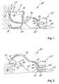
- tool system 10has a diamond drill as electric hand tool 11 with a diamond drill bit as a tool 12 to create a borehole 7 in a wall as a component 6.
- a water hose 13arranged at a water connection 8 and connected to the electric hand tool device 11, water as coolant is supplied to the tool 12 via the electric hand tool 11 during the drilling process.
- a wegersharende from the housing 14 of the electric hand tool 11 electric line 15is provided for feeding the electric power tool 11, which has a male connector part 16 at its free end.
- the resulting muddy overburdenconsisting of water, drilling dust and possibly cuttings, is collected in a collecting ring as tool-side dirt collecting device 21 of the tool system 10 so that it does not pollute the environment around the borehole 7 to be created.
- a connecting piece 22is provided at the formed as a collecting ring dirt collecting device 21, .
- the tool system 10comprises an autonomous, movable vacuum cleaner as suction device 31 for discharging the dirt accumulating in the tool device-side dirt collecting device 21, which is fed via an input line 32 arranged on a mains connection (not shown here).
- a connection piece 33is provided on the suction device 31, on which one end of the suction hose 34 is arranged.
- the other end of the suction hose 34is arranged on the connecting piece 22 of the dirt collecting device 21, so that during operation of the suction device 31, the dirt accumulating in the tool device-side dirt collecting device 21 can be removed.
- an AC / DC converter 38is provided which can convert the AC current supplied through the input line 32 into a DC current.
- an electrical output 35is further provided in the form of a female plug part, in which the male plug part 16 of the electric wire 15 of the electric hand tool 11 for the same is arranged.
- a switching device 36is provided, with which either AC voltage or DC voltage at the electrical output 35 can be made available as a function of the corresponding switch position.
- Tool system 40 shownhas a separating device as an electric hand tool unit 41 with a cutting wheel as a tool 42 for creating a slot 9 in a component 6.
- the resulting dustis collected in a suction hood as a tool device-side dirt collecting device 51, the one Connecting piece 52 for connection of a suction hose 64 has.
- the suction hose 64is further connected to the connecting piece 63 of the suction device 61, so that the resulting dust can be removed via the suction device 61.
- the suction device 61has a current accumulator 66 in the form of rechargeable battery cells, for example Li-ion or Li-polymer rechargeable battery cells.
- the power storage device 66is rechargeable via a charging device 67 provided in the suction device 61.
- an AC / DC converter 68is provided which converts the AC current supplied through the input line 62 into a DC current.
- the suction device 61can be operated on the one hand via the mains voltage and on the other hand via the voltage of the current memory 66.
- the suction device 31may be provided with a power storage and / or a charger (in Fig. 1 not shown). If a power accumulator is provided in the suction device 31, the suction device 31 can also be operated on the one hand via the mains voltage and on the other hand via the voltage of the current accumulator.
- the DC-powered electric hand tool unit 41is supplied via the connected to the electrical output 65 of the suction device 61, away from the housing 44 of the electric power tool 41 extending line 45 with DC. Furthermore, a second electrical output 69 is provided on the suction device 61, via which an AC voltage for operating an AC-operated electric hand tool device, such as the electric hand tool 11 in Fig. 1 , is provided.
Landscapes
- Engineering & Computer Science (AREA)
- Mechanical Engineering (AREA)
- Auxiliary Devices For Machine Tools (AREA)
- Secondary Cells (AREA)
- Cleaning In General (AREA)
Abstract
Description
Translated fromGermanDie Erfindung betrifft ein Werkzeugsystem mit einem Elektrohandwerkzeuggerät, einer werkzeuggerätseitigen Schmutzsammeleinrichtung und mit einer Saugeinrichtung, der im Oberbegriff des Patentanspruchs 1 genannten Art.The invention relates to a tool system with an electric hand tool, a tool device side dirt collector and with a suction device referred to in the preamble of claim 1. Art.
Beim Arbeiten mit Elektrohandwerkzeuggeräten, wie z. B. mit Bohrhämmern oder mit Trenn- und Schleifgeräten, entsteht Staub, der die Umgebung verschmutzen kann. Beim Arbeiten mit Elektrohandwerkzeuggeräten, bei denen das Werkzeug während dem Bohrvorgang mit einem Fluid, wie Wasser gekühlt wird, z. B. bei Bohrgeräten mit einer Diamantbohrkrone, fällt ein schlammiger Abraum aus Wasser und Bohrstaub beziehungsweise Bohrkleins an, der die Umgebung verschmutzen kann. Unter Elektrohandwerkzeuggerät wird in diesem Zusammenhang auch ein ständergeführtes Bohrgerät verstanden, wie es beispielsweise zum Erstellen von Diamantbohrungen zur Anwendung kommt.When working with electrical hand tools, such. B. with rotary hammers or with separation and grinding equipment, creates dust that can pollute the environment. When working with electrical hand tool devices in which the tool during the drilling process with a fluid such as water is cooled, for. As in drilling rigs with a diamond core bit, falls to a muddy overburden of water and drilling dust or cuttings, which can pollute the environment. Under electric hand tool device is understood in this context, a stand-guided drill, as it comes, for example, for creating diamond drill holes for use.
Es werden deshalb werkzeuggerätseitige Schmutzsammeleinrichtungen vorgesehen, in denen der beim Arbeiten anfallende Schmutz über eine Saugeinrichtung, wie beispielsweise einen Staubsauger oder ein (Bohr-) Wasser-Recyclinggerät, von der Arbeitsstelle ohne Verschmutzung der benachbarten Umgebung abgeführt wird.There are therefore provided tool-side dirt collecting devices, in which the accumulated dirt during work on a suction device, such as a vacuum cleaner or a (drilling) water recycling device, is discharged from the workplace without contamination of the adjacent environment.
Aus der
Aus der
Aus der
Aus der
Aus der
Nachteilig an den bekannten Lösungen ist, dass das Elektrowerkzeuggerät und die Saugeinrichtung für den Betrieb separat gespiesen werden müssen und daher mehrere Kabel getrennt voneinander auf der Baustelle geführt werden müssen. Neben dem mühsamen Handling des Werkzeugsystems sind zudem mehrere Anschlüsse zum Betrieb des Werkzeugsystems erforderlich.A disadvantage of the known solutions that the power tool and the suction device must be fed separately for operation and therefore several cables must be performed separately on the construction site. In addition to the tedious handling of the tool system, several connections are required for operating the tool system.
Aufgabe der Erfindung ist es, ein gattungsgemässes Werkzeugsystem zu schaffen, das die vorgenannten Nachteile nicht aufweist und das insbesondere einfach handhabbar ist.The object of the invention is to provide a generic tool system that does not have the aforementioned disadvantages and in particular is easy to handle.
Die Aufgabe ist durch die Merkmale des unabhängigen Anspruchs gelöst. Vorteilhafte Weiterbildungen sind in den Unteransprüchen dargelegt.The object is solved by the features of the independent claim. Advantageous developments are set forth in the subclaims.
Gemäss der Erfindung ist an der Saugeinrichtung ein elektrischer Ausgang für eine sich vom Gehäuse des Elektrohandwerkzeuggerätes wegerstreckende elektrische Leitung zur Speisung des Elektrohandwerkzeuggerätes vorgesehen.According to the invention, an electrical output for a wegerstreckende from the housing of the electric hand tool device electrical line for feeding the electric hand tool device is provided on the suction device.
Das Elektrowerkzeuggerät wird direkt über die autonome und verfahrbare Saugeinrichtung gespiesen, womit die Saugeinrichtung dem Anwender bei jeder Art von Arbeit mit dem entsprechenden, Schmutz erzeugenden Elektrowerkzeuggerät jederzeit zur Verfügung steht. Die Saugeinrichtung selbst weist eine eigene Stromversorgung auf, welche beispielsweise über eine an einem Netzanschluss anordnenbare Eingangsleitung hergestellt wird. Vorteilhaft ist die Saugeinrichtung mit Rollen versehen, womit die Saugeinrichtung auf der Baustelle einfach umpositionierbar ist. Für den Betrieb des Werkzeugsystems sind nur ein externer Netzanschluss und gegebenenfalls ein Verlängerungskabel erforderlich, womit weniger Leitungen auf der Baustelle vorhanden sind und der logistische Aufwand für den Anwender reduziert ist.The power tool is fed directly via the autonomous and movable suction device, so that the suction device is available to the user at any kind of work with the corresponding, dirt-generating power tool at any time. The suction device itself has its own power supply, which is produced, for example, via an input line which can be arranged at a mains connection. Advantageously, the suction device is provided with rollers, whereby the suction device on the site is easily repositioned. For the operation of the tool system only an external power supply and possibly an extension cable are required, which fewer cables are available on the site and the logistical effort for the user is reduced.
Das Elektrowerkzeug wird vorteilhaft mit seiner Leitung direkt an dem elektrischen Ausgang der Saugeinrichtung angeschlossen, weshalb der elektrische Ausgang vorzugsweise als weiblicher Steckerteil ausgebildet ist, der entsprechend zur Aufnahme eines herkömmlichen beziehungsweise landesüblichen männlichen Steckerteils ausgebildet ist, das an der Leitung des Elektrowerkzeuggerätes vorgesehen ist. Das Elektrowerkzeuggerät ist ein Teil des Werkzeugsystems und somit mit diesem verwendbar. Andererseits kann das Elektrowerkzeuggerät bedarfsweise auch autonom verwendet werden, indem es an einem Netzanschluss angeschlossen und somit über diesen gespiesen wird.The power tool is advantageously connected with its line directly to the electrical output of the suction device, which is why the electrical output is preferably designed as a female connector part which is designed to receive a conventional or customary male male part, which is provided on the line of the power tool. The power tool is a part of the tool system and thus usable with this. On the other hand, if necessary, the power tool device can also be used autonomously by being connected to a mains connection and thus being fed via it.
Das Werkzeugsystem lässt sich in Bezug auf den elektrischen und mechanischen Wirkungsgrad seiner Komponenten beziehungsweise seiner Leistungsnehmer optimieren, womit die zur Verfügung stehende elektrische Energie optimal nutzbar ist.The tool system can be optimized with respect to the electrical and mechanical efficiency of its components or its service users, so that the available electrical energy is optimally usable.
Vorzugsweise weist die Saugeinrichtung einen Stromspeicher auf, der beispielsweise eine Batteriezelleneinheit oder Akkuzelleneinheit umfasst. Das Elektrowerkzeuggerät wird beispielsweise direkt von dem Stromspeicher gespiesen. Alternativ oder ergänzend dient der Stromspeicher der Speisung der Saugeinrichtung, womit die Saugeinrichtung sowie das Elektrowerkzeuggerät auch ohne eine externe Stromquelle betreibbar sind. Der Stromspeicher gibt vorteilhaft eine Gleichspannung ab, welche einen Betrieb eines Gleichstrom-betriebenen Elektrohandwerkzeuggerätes ermöglicht, wie es beispielsweise als Akkugerät bekannt ist.Preferably, the suction device has a power storage, which comprises, for example, a battery cell unit or battery cell unit. The power tool, for example, fed directly from the power storage. Alternatively or additionally, the power storage device serves to supply the suction device, with which the suction device and the power tool device can also be operated without an external power source. The power storage device advantageously outputs a DC voltage, which enables operation of a DC-operated electric hand tool device, as is known, for example, as a cordless device.
Der Stromspeicher ist beispielsweise von der Saugeinrichtung abnehmbar ausgebildet und kann an einem anderen Gleichstrom-betriebenen Elektrogerät angeordnet werden. Beispielsweise kann der Stromspeicher an einem Gleichstrom-betriebenen Elektrohandwerkzeuggerät, wie ein Akkugerät, angeordnet werden und dieses direkt speisen. Mit einem Gleichstrom-betriebenen Elektrohandwerkzeuggerät lassen sich die elektrischen Verluste bei der Durchleitung der elektrischen Energie reduzieren, da die Umwandlung von einer Gleichstromspannung, wie sie von einem Stromspeicher üblicherweise zur Verfügung gestellt wird, in eine Wechselstromspannung verlustbehaftet ist.The power accumulator is designed, for example, removable from the suction device and can be arranged on another DC-powered electrical appliance. For example, the power storage on a DC-powered electric hand tool, such as a cordless device, be arranged and feed this directly. With a DC powered handheld power tool, the electrical losses in the passage of the electrical energy can be reduced, since the conversion of a DC voltage, as it is usually provided by a power storage, is lossy in an AC voltage.
Bevorzugt weist die Saugeinrichtung ein Ladegerät zum Laden des Stromspeichers auf, womit der Stromspeicher nach seiner Entladung wieder aufladbar ist. Das Ladegerät ist vorteilhaft mit einer mit einem Netzanschluss verbindbaren Eingangsleitung der Saugeinrichtung verbunden.Preferably, the suction device to a charger for charging the power storage, whereby the power storage is rechargeable after its discharge. The charger is advantageously connected to a connectable to a network connection input line of the suction device.
Vorzugsweise weist die Saugeinrichtung einen Wechselstrom-/Gleichstromwandler auf, der den eingangsseitigen Wechselstrom in einen Gleichstrom umwandelt. An dem elektrischen Ausgang der Saugeinrichtung steht vorteilhaft Gleichstrom zur Verfügung, welche einen Betrieb eines Gleichstrom-betriebenen Elektrohandwerkzeuggerätes ermöglicht. Des Weiteren werden an ein mit Gleichstrom-betriebenes Werkzeugsystem geringere sicherheitstechnische Anforderungen als ein nur mit Wechselstrom-betriebenes Werkzeugsystem gestellt.Preferably, the suction device comprises an AC / DC converter, which converts the AC input side into a DC current. At the electric Output of the suction device is advantageously DC available, which allows operation of a DC-powered electric hand tool device. Furthermore, lower safety requirements than with an AC-powered tool system are imposed on a DC-powered tool system.
Bevorzugt ist eine Umschalteinrichtung zur wahlweisen Bereitstellung von Wechselstromspannung oder Gleichstromspannung an dem elektrischen Ausgang vorgesehen, womit an einem elektrischen Ausgang der Saugeinrichtung wahlweise ein Gleichstrom-betriebenes oder ein Wechselstrom-betriebenes Elektrohandwerkzeuggerät zur Speisung desselben angeschlossen werden kann. Die Umschalteinrichtung umfasst beispielsweise eine Schalteranordnung um an dem elektrischen Ausgang je nach Schalterstellung die entsprechende Spannung zur Verfügung zu stellen. Alternativ weist der Steckerteil des Elektrohandwerkzeuggerätes je nach Art der Spannung zum Betrieb des Elektrohandwerkzeuggerätes eine unterschiedliche Ausgestaltung auf, so dass beim Anschluss des Steckerteils über eine Mechanik und/oder Elektronik die für den Betreib des Elektrohandwerkzeuggerätes richtige Spannungsart am elektrischen Anschluss von der Saugeinrichtung zur Verfügung gestellt wird.Preferably, a switching means for selectively providing AC voltage or DC voltage to the electrical output is provided, whereby at an electrical output of the suction device either a DC-powered or an AC-powered electric hand tool device for feeding the same can be connected. The switching device comprises, for example, a switch arrangement in order to provide the corresponding voltage at the electrical output, depending on the switch position. Alternatively, the plug part of the electric hand tool device, depending on the type of voltage for operating the electric hand tool device on a different configuration, so that when connecting the plug part via a mechanics and / or electronics for the operation of the electric hand tool device correct voltage at the electrical connection of the suction provided becomes.
Vorzugsweise sind ein erster elektrischer Ausgang zur Bereitstellung von Gleichstromspannung und ein zweiter elektrischer Ausgang zur Bereitstellung von Wechselstromspannung an der Saugeinrichtung vorgesehen. Entsprechend der erforderlichen Spannungsart des Elektrohandwerkzeuggerätes wird dieses an dem ersten oder an dem zweiten elektrischen Ausgang angeschlossen. Da üblicherweise die Steckerteile eines Gleichstrom-betriebenen und eines Wechselstrom-betriebenen Elektrohandwerkzeuggerät unterschiedlich ausgebildet sind, wird ein Fehlanschluss des Elektrohandwerkzeuggerätes ausgeschlossen.Preferably, a first electrical output for providing DC voltage and a second electrical output for providing AC voltage to the suction device are provided. According to the required voltage of the electric hand tool device, this is connected to the first or to the second electrical output. Since usually the plug parts of a DC-powered and an AC-powered electric hand tool device are designed differently, a faulty connection of the electric hand tool device is excluded.
Die Erfindung wird nachstehend anhand von Ausführungsbeispielen näher erläutert. Es zeigen:
Fig. 1 Ein erstes Ausführungsbeispiel eines Werkzeugsystems in Seitenansicht; undFig. 2 ein zweites Ausführungsbeispiel eines Werkzeugsystems in Seitenansicht.
Fig. 1 A first embodiment of a tool system in side view; andFig. 2 a second embodiment of a tool system in side view.
Grundsätzlich sind in den Figuren gleiche Teile mit den gleichen Bezugszeichen versehen.Basically, the same parts are provided with the same reference numerals in the figures.
Das in der
Der dabei entstehende schlammige Abraum, bestehend aus Wasser, Bohrmehl und allenfalls Bohrklein, wird in einem Auffangring als werkzeuggerätseitige Schmutzsammeleinrichtung 21 des Werkzeugsystems 10 aufgefangen, so dass dieser die Umgebung um das zu erstellende Bohrloch 7 nicht verschmutzt. An der als Auffangring ausgebildeten Schmutzsammeleinrichtung 21 ist ein Anschlussstutzen 22 vorgesehen.The resulting muddy overburden, consisting of water, drilling dust and possibly cuttings, is collected in a collecting ring as tool-side dirt collecting
Weiter umfasst das Werkzeugsystem 10 einen autonomen, verfahrbaren Staubsauger als Saugeinrichtung 31 zum Abführen des in der werkzeuggerätseitigen Schmutzsammeleinrichtung 21 anfallenden Schmutzes, der über eine an einem - hier nicht dargestellten - Netzanschluss angeordnete Eingangsleitung 32 gespiesen wird. Weiter ist ein Anschlussstutzen 33 an der Saugeinrichtung 31 vorgesehen, an dem das eine Ende des Saugschlauchs 34 angeordnet ist. Das andere Ende des Saugschlauchs 34 ist an dem Anschlussstutzen 22 der Schmutzsammeleinrichtung 21 angeordnet, so dass im Betrieb der Saugeinrichtung 31 der in der werkzeuggerätseitigen Schmutzsammeleinrichtung 21 anfallende Schmutz abgeführt werden kann. Weiter ist ein Wechselstrom-/Gleichstromwandler 38 vorgesehen, der den über die Eingangsleitung 32 zugeführten Wechselstrom in einem Gleichstrom umwandeln kann.Furthermore, the
An der Saugeinrichtung 31 ist weiter ein elektrischer Ausgang 35 in Form eines weiblichen Steckerteils vorgesehen, in welches das männliche Steckerteil 16 der elektrischen Leitung 15 des Elektrohandwerkzeuggerätes 11 zur Speisung desselben angeordnet wird. An dem elektrischen Ausgang 35 ist eine hier nicht näher dargestellte Umschaltvorrichtung 36 vorgesehen, mit der in Abhängigkeit der entsprechenden Schalterstellung wahlweise Wechselstromspannung oder Gleichstromspannung an dem elektrischen Ausgang 35 zur Verfügung gestellt werden kann.At the
Das in der
Die Saugeinrichtung 61 weist im Gegensatz zu der zuvor dargelegten Saugeinrichtung 31 einen Stromspeicher 66 in Form von Akkuzellen, beispielsweise Li-lonen- oder Li-Polymer-Akkuzellen auf. Der Stromspeicher 66 ist über ein in der Saugeinrichtung 61 vorgesehenes Ladegerät 67 wiederaufladbar. Weiter ist ein Wechselstrom-/Gleichstromwandler 68 vorgesehen, der den über die Eingangsleitung 62 zugeführten Wechselstrom in einem Gleichstrom umwandelt. Die Saugeinrichtung 61 kann einerseits über die Netzspannung und andererseits über die Spannung des Stromspeichers 66 betrieben werden.In contrast to the
Auch die Saugeinrichtung 31 kann mit einem Stromspeicher und/oder einem Ladegerät versehen sein (in
Das Gleichstrom-betriebene Elektrohandwerkzeuggerät 41 wird über die an dem elektrischen Ausgang 65 der Saugeinrichtung 61 angeschlossenen, sich vom Gehäuse 44 des Elektrohandwerkzeuggerätes 41 wegerstreckende Leitung 45 mit Gleichstrom versorgt. Weiter ist ein zweiter elektrischer Ausgang 69 an der Saugeinrichtung 61 vorgesehen, über den eine Wechselspannung zum Betrieb eines Wechselstrom-betriebenen Elektrohandwerkzeuggerätes, wie das Elektrohandwerkzeuggerät 11 in
Claims (6)
Translated fromGermanan der Saugeinrichtung (31; 61) ein elektrischer Ausgang (35; 65, 69) für eine sich vom Gehäuse (14; 44) des Elektrohandwerkzeuggerätes (11; 41) wegerstreckende elektrische Leitung (15; 45) zur Speisung des Elektrohandwerkzeuggerätes (11; 41) vorgesehen ist.Tool system comprising an electric hand tool device (11; 41), a tool device side dirt collecting device (21; 51) and with a suction device (31; 61) for discharging the dirt accumulating in the tool device side dirt collecting device (21; 51),characterized in that
an electric outlet (35; 65, 69) for an electrical line (15; 45) extending from the housing (14; 44) of the electric hand tool device (11; 41) for feeding the electric hand tool device (11; 41) is provided.
Applications Claiming Priority (1)
| Application Number | Priority Date | Filing Date | Title |
|---|---|---|---|
| DE102008054489ADE102008054489A1 (en) | 2008-12-10 | 2008-12-10 | Tooling system |
Publications (2)
| Publication Number | Publication Date |
|---|---|
| EP2196282A1true EP2196282A1 (en) | 2010-06-16 |
| EP2196282B1 EP2196282B1 (en) | 2011-09-28 |
Family
ID=41820394
Family Applications (1)
| Application Number | Title | Priority Date | Filing Date |
|---|---|---|---|
| EP09176121AActiveEP2196282B1 (en) | 2008-12-10 | 2009-11-16 | Tool system |
Country Status (4)
| Country | Link |
|---|---|
| EP (1) | EP2196282B1 (en) |
| AT (1) | ATE526111T1 (en) |
| DE (1) | DE102008054489A1 (en) |
| DK (1) | DK2196282T3 (en) |
Cited By (3)
| Publication number | Priority date | Publication date | Assignee | Title |
|---|---|---|---|---|
| NL2009274C2 (en)* | 2012-08-03 | 2014-02-04 | Dapan B V | HOOK GRINDING DEVICE. |
| EP3772385A1 (en)* | 2019-08-08 | 2021-02-10 | Hilti Aktiengesellschaft | System and method for driving a machine tool into a wall or a ground |
| US12357136B2 (en) | 2020-11-19 | 2025-07-15 | Milwaukee Electric Tool Corporation | Portable dust extractor |
Families Citing this family (7)
| Publication number | Priority date | Publication date | Assignee | Title |
|---|---|---|---|---|
| DE102010040336A1 (en) | 2010-09-07 | 2012-03-08 | Alfred Kärcher Gmbh & Co. Kg | Device and method for detecting a change in operating state of a power tool and vacuum cleaner |
| DE202011105240U1 (en) | 2011-08-26 | 2012-05-23 | Herwig Bohrtechnik Schmalkalden Gmbh | Apparatus for use in the dry drilling process to minimize fiber and particulate emissions |
| EP2628428B1 (en)* | 2012-02-17 | 2019-05-22 | Festool GmbH | Suction device with a charging device |
| DE102013018278A1 (en)* | 2013-10-31 | 2015-04-30 | Metabowerke Gmbh | Multi-purpose vacuum cleaners |
| DE102016008346B4 (en) | 2016-07-11 | 2023-06-29 | Fritz Acksteiner | dust collector |
| DE202017106772U1 (en) | 2017-11-08 | 2017-11-20 | Mario Jakopec | Drilling dust suction device |
| DE102022107517A1 (en) | 2022-03-30 | 2023-10-05 | MAFELL Aktiengesellschaft | Mobile suction device |
Citations (10)
| Publication number | Priority date | Publication date | Assignee | Title |
|---|---|---|---|---|
| GB441351A (en) | 1935-02-06 | 1936-01-17 | Pyrene Co Ltd | Improvements relating to apparatus for trapping dust in connection with bore holes |
| DE8813719U1 (en) | 1988-11-03 | 1989-08-03 | dth Diamant-Technik-Herdecke GmbH, 5804 Herdecke | Hand rotary drill with ring core bit |
| DE3805962A1 (en) | 1988-02-25 | 1989-09-07 | Festo Kg | PLATE GRINDING MACHINE |
| EP0377100A1 (en)* | 1988-12-30 | 1990-07-11 | C. & E. FEIN GmbH & Co. | Vacuum cleaner and dust-free working tool |
| FR2690328A1 (en) | 1992-04-28 | 1993-10-29 | Ducasse Xavier | Vacuum cleaner with cylindrical drum and integral energy source - uses cylindrical drum divided into lower compartment housing battery and upper compartment with suction unit and dust collector |
| US6053674A (en) | 1999-03-04 | 2000-04-25 | Thompson; John Eugene | Dust collector assembly for drilling tools |
| EP1240976A1 (en)* | 2001-03-14 | 2002-09-18 | HILTI Aktiengesellschaft | Suction module |
| EP1321247A2 (en)* | 2001-12-21 | 2003-06-25 | Guido Valentini | Portable container for an electric tool with dust suction and collection capacity |
| EP1391263A1 (en)* | 2002-08-21 | 2004-02-25 | Hitachi Koki Co., Ltd. | Dust collector |
| EP1477272A1 (en)* | 2003-03-21 | 2004-11-17 | BLACK & DECKER INC. | Cordless hand held power tool with power accessory |
Family Cites Families (5)
| Publication number | Priority date | Publication date | Assignee | Title |
|---|---|---|---|---|
| DE2925908A1 (en)* | 1979-06-27 | 1981-01-29 | Licentia Gmbh | Hand drill exhausting swarf accessory - has fan driven by separate motor powered by battery |
| JP2553485Y2 (en)* | 1991-04-19 | 1997-11-05 | 株式会社マキタ | External power supply mechanism for dust collector |
| JP4021625B2 (en)* | 2001-02-01 | 2007-12-12 | 株式会社マキタ | Dust collector and electric tool |
| DE102004033844A1 (en)* | 2004-07-13 | 2006-02-09 | Robert Bosch Gmbh | Power supply device for multiple output voltages |
| DE102007019646A1 (en)* | 2007-04-26 | 2008-10-30 | Robert Bosch Gmbh | Hose arrangement for e.g. grinding machine, has supply line supplying energy to drive unit that drives machine tool, extraction hose for suction of abrasive dust, where supply line and extraction hose are combined into common hose line |
- 2008
- 2008-12-10DEDE102008054489Apatent/DE102008054489A1/ennot_activeCeased
- 2009
- 2009-11-16ATAT09176121Tpatent/ATE526111T1/enactive
- 2009-11-16EPEP09176121Apatent/EP2196282B1/enactiveActive
- 2009-11-16DKDK09176121.3Tpatent/DK2196282T3/enactive
Patent Citations (10)
| Publication number | Priority date | Publication date | Assignee | Title |
|---|---|---|---|---|
| GB441351A (en) | 1935-02-06 | 1936-01-17 | Pyrene Co Ltd | Improvements relating to apparatus for trapping dust in connection with bore holes |
| DE3805962A1 (en) | 1988-02-25 | 1989-09-07 | Festo Kg | PLATE GRINDING MACHINE |
| DE8813719U1 (en) | 1988-11-03 | 1989-08-03 | dth Diamant-Technik-Herdecke GmbH, 5804 Herdecke | Hand rotary drill with ring core bit |
| EP0377100A1 (en)* | 1988-12-30 | 1990-07-11 | C. & E. FEIN GmbH & Co. | Vacuum cleaner and dust-free working tool |
| FR2690328A1 (en) | 1992-04-28 | 1993-10-29 | Ducasse Xavier | Vacuum cleaner with cylindrical drum and integral energy source - uses cylindrical drum divided into lower compartment housing battery and upper compartment with suction unit and dust collector |
| US6053674A (en) | 1999-03-04 | 2000-04-25 | Thompson; John Eugene | Dust collector assembly for drilling tools |
| EP1240976A1 (en)* | 2001-03-14 | 2002-09-18 | HILTI Aktiengesellschaft | Suction module |
| EP1321247A2 (en)* | 2001-12-21 | 2003-06-25 | Guido Valentini | Portable container for an electric tool with dust suction and collection capacity |
| EP1391263A1 (en)* | 2002-08-21 | 2004-02-25 | Hitachi Koki Co., Ltd. | Dust collector |
| EP1477272A1 (en)* | 2003-03-21 | 2004-11-17 | BLACK & DECKER INC. | Cordless hand held power tool with power accessory |
Cited By (5)
| Publication number | Priority date | Publication date | Assignee | Title |
|---|---|---|---|---|
| NL2009274C2 (en)* | 2012-08-03 | 2014-02-04 | Dapan B V | HOOK GRINDING DEVICE. |
| EP3772385A1 (en)* | 2019-08-08 | 2021-02-10 | Hilti Aktiengesellschaft | System and method for driving a machine tool into a wall or a ground |
| WO2021023543A1 (en)* | 2019-08-08 | 2021-02-11 | Hilti Aktiengesellschaft | System and method for driving a machine tool into a wall or a substrate |
| US12185897B2 (en) | 2019-08-08 | 2025-01-07 | Hilti Aktiengesellschaft | System and method for driving a power tool into a substrate using a negative pressure produced by a suction device |
| US12357136B2 (en) | 2020-11-19 | 2025-07-15 | Milwaukee Electric Tool Corporation | Portable dust extractor |
Also Published As
| Publication number | Publication date |
|---|---|
| ATE526111T1 (en) | 2011-10-15 |
| DK2196282T3 (en) | 2011-11-14 |
| DE102008054489A1 (en) | 2010-06-17 |
| EP2196282B1 (en) | 2011-09-28 |
Similar Documents
| Publication | Publication Date | Title |
|---|---|---|
| EP2196282B1 (en) | Tool system | |
| EP1240976B1 (en) | Suction module | |
| EP3272261B1 (en) | Portable cleaning device with battery pack | |
| WO2011047975A1 (en) | Hand-held tool, auxiliary measuring device for a hand-held tool and battery for hand-held tool | |
| EP2878249B1 (en) | Multipurpose vacuum cleaner | |
| WO2008145443A1 (en) | Hand-propelled appliance, in particular vacuum cleaner | |
| DE2925908A1 (en) | Hand drill exhausting swarf accessory - has fan driven by separate motor powered by battery | |
| DE102010016244B4 (en) | Vacuum lifting device with electrically driven pump and power supply in the handle | |
| EP2478612B1 (en) | Rechargeable battery for hand tool | |
| EP2535149A2 (en) | Electric work device with an electric engine, in particular a hand-held electric tool | |
| DE3516099A1 (en) | Hand-held machine tool with an electric motor drive | |
| EP3875225A1 (en) | Energy supply device for a machine tool | |
| WO2000018546A1 (en) | Energy supply for an electrical hand-held appliance | |
| EP2174749B1 (en) | Dust suction for a rechargeable electrical manual tool machine | |
| EP2451002A1 (en) | Method and charger for charging at least two batteries | |
| CN114552692A (en) | Energy supply device and system comprising same | |
| WO2016142461A1 (en) | Rechargeable tool battery, mains-operable hand-held power tool, and tool system | |
| EP4289562A1 (en) | Machine tool with parallel output and motor axes | |
| WO2023247108A1 (en) | Electrical machining device and system comprising an electrical machining device and an external energy supply device | |
| DE102014222370A1 (en) | Battery pack for a hand tool | |
| DE102021202879A1 (en) | Energy supply device for a hand-held power tool | |
| WO2019170832A1 (en) | Rotationally drivable rotary tool device | |
| DE102023211315A1 (en) | System consisting of an electric motor-driven hand tool and at least one power supply cable connectable to the hand tool | |
| DE9402335U1 (en) | Battery powered electrical device | |
| EP4297934A1 (en) | Device and system for supplying a machine tool with electric energy, and use of the device for this purpose |
Legal Events
| Date | Code | Title | Description |
|---|---|---|---|
| PUAI | Public reference made under article 153(3) epc to a published international application that has entered the european phase | Free format text:ORIGINAL CODE: 0009012 | |
| AK | Designated contracting states | Kind code of ref document:A1 Designated state(s):AT BE BG CH CY CZ DE DK EE ES FI FR GB GR HR HU IE IS IT LI LT LU LV MC MK MT NL NO PL PT RO SE SI SK SM TR | |
| AX | Request for extension of the european patent | Extension state:AL BA RS | |
| 17P | Request for examination filed | Effective date:20101216 | |
| 17Q | First examination report despatched | Effective date:20110117 | |
| GRAP | Despatch of communication of intention to grant a patent | Free format text:ORIGINAL CODE: EPIDOSNIGR1 | |
| RIC1 | Information provided on ipc code assigned before grant | Ipc:B23Q 11/00 20060101AFI20110607BHEP | |
| GRAS | Grant fee paid | Free format text:ORIGINAL CODE: EPIDOSNIGR3 | |
| GRAA | (expected) grant | Free format text:ORIGINAL CODE: 0009210 | |
| AK | Designated contracting states | Kind code of ref document:B1 Designated state(s):AT BE BG CH CY CZ DE DK EE ES FI FR GB GR HR HU IE IS IT LI LT LU LV MC MK MT NL NO PL PT RO SE SI SK SM TR | |
| REG | Reference to a national code | Ref country code:GB Ref legal event code:FG4D Free format text:NOT ENGLISH | |
| REG | Reference to a national code | Ref country code:CH Ref legal event code:EP | |
| REG | Reference to a national code | Ref country code:IE Ref legal event code:FG4D | |
| REG | Reference to a national code | Ref country code:DK Ref legal event code:T3 | |
| REG | Reference to a national code | Ref country code:DE Ref legal event code:R096 Ref document number:502009001459 Country of ref document:DE Effective date:20111124 | |
| REG | Reference to a national code | Ref country code:NL Ref legal event code:VDEP Effective date:20110928 | |
| REG | Reference to a national code | Ref country code:SE Ref legal event code:TRGR | |
| PG25 | Lapsed in a contracting state [announced via postgrant information from national office to epo] | Ref country code:LT Free format text:LAPSE BECAUSE OF FAILURE TO SUBMIT A TRANSLATION OF THE DESCRIPTION OR TO PAY THE FEE WITHIN THE PRESCRIBED TIME-LIMIT Effective date:20110928 Ref country code:HR Free format text:LAPSE BECAUSE OF FAILURE TO SUBMIT A TRANSLATION OF THE DESCRIPTION OR TO PAY THE FEE WITHIN THE PRESCRIBED TIME-LIMIT Effective date:20110928 Ref country code:NO Free format text:LAPSE BECAUSE OF FAILURE TO SUBMIT A TRANSLATION OF THE DESCRIPTION OR TO PAY THE FEE WITHIN THE PRESCRIBED TIME-LIMIT Effective date:20111228 Ref country code:FI Free format text:LAPSE BECAUSE OF FAILURE TO SUBMIT A TRANSLATION OF THE DESCRIPTION OR TO PAY THE FEE WITHIN THE PRESCRIBED TIME-LIMIT Effective date:20110928 | |
| LTIE | Lt: invalidation of european patent or patent extension | Effective date:20110928 | |
| PG25 | Lapsed in a contracting state [announced via postgrant information from national office to epo] | Ref country code:CY Free format text:LAPSE BECAUSE OF FAILURE TO SUBMIT A TRANSLATION OF THE DESCRIPTION OR TO PAY THE FEE WITHIN THE PRESCRIBED TIME-LIMIT Effective date:20110928 Ref country code:SI Free format text:LAPSE BECAUSE OF FAILURE TO SUBMIT A TRANSLATION OF THE DESCRIPTION OR TO PAY THE FEE WITHIN THE PRESCRIBED TIME-LIMIT Effective date:20110928 Ref country code:GR Free format text:LAPSE BECAUSE OF FAILURE TO SUBMIT A TRANSLATION OF THE DESCRIPTION OR TO PAY THE FEE WITHIN THE PRESCRIBED TIME-LIMIT Effective date:20111229 Ref country code:LV Free format text:LAPSE BECAUSE OF FAILURE TO SUBMIT A TRANSLATION OF THE DESCRIPTION OR TO PAY THE FEE WITHIN THE PRESCRIBED TIME-LIMIT Effective date:20110928 | |
| REG | Reference to a national code | Ref country code:IE Ref legal event code:FD4D | |
| PG25 | Lapsed in a contracting state [announced via postgrant information from national office to epo] | Ref country code:SK Free format text:LAPSE BECAUSE OF FAILURE TO SUBMIT A TRANSLATION OF THE DESCRIPTION OR TO PAY THE FEE WITHIN THE PRESCRIBED TIME-LIMIT Effective date:20110928 Ref country code:CZ Free format text:LAPSE BECAUSE OF FAILURE TO SUBMIT A TRANSLATION OF THE DESCRIPTION OR TO PAY THE FEE WITHIN THE PRESCRIBED TIME-LIMIT Effective date:20110928 Ref country code:IS Free format text:LAPSE BECAUSE OF FAILURE TO SUBMIT A TRANSLATION OF THE DESCRIPTION OR TO PAY THE FEE WITHIN THE PRESCRIBED TIME-LIMIT Effective date:20120128 | |
| BERE | Be: lapsed | Owner name:HILTI AKTIENGESELLSCHAFT Effective date:20111130 | |
| PG25 | Lapsed in a contracting state [announced via postgrant information from national office to epo] | Ref country code:PT Free format text:LAPSE BECAUSE OF FAILURE TO SUBMIT A TRANSLATION OF THE DESCRIPTION OR TO PAY THE FEE WITHIN THE PRESCRIBED TIME-LIMIT Effective date:20120130 Ref country code:NL Free format text:LAPSE BECAUSE OF FAILURE TO SUBMIT A TRANSLATION OF THE DESCRIPTION OR TO PAY THE FEE WITHIN THE PRESCRIBED TIME-LIMIT Effective date:20110928 Ref country code:EE Free format text:LAPSE BECAUSE OF FAILURE TO SUBMIT A TRANSLATION OF THE DESCRIPTION OR TO PAY THE FEE WITHIN THE PRESCRIBED TIME-LIMIT Effective date:20110928 Ref country code:RO Free format text:LAPSE BECAUSE OF FAILURE TO SUBMIT A TRANSLATION OF THE DESCRIPTION OR TO PAY THE FEE WITHIN THE PRESCRIBED TIME-LIMIT Effective date:20110928 | |
| PG25 | Lapsed in a contracting state [announced via postgrant information from national office to epo] | Ref country code:MC Free format text:LAPSE BECAUSE OF NON-PAYMENT OF DUE FEES Effective date:20111130 | |
| PG25 | Lapsed in a contracting state [announced via postgrant information from national office to epo] | Ref country code:IE Free format text:LAPSE BECAUSE OF FAILURE TO SUBMIT A TRANSLATION OF THE DESCRIPTION OR TO PAY THE FEE WITHIN THE PRESCRIBED TIME-LIMIT Effective date:20110928 | |
| PLBE | No opposition filed within time limit | Free format text:ORIGINAL CODE: 0009261 | |
| STAA | Information on the status of an ep patent application or granted ep patent | Free format text:STATUS: NO OPPOSITION FILED WITHIN TIME LIMIT | |
| PG25 | Lapsed in a contracting state [announced via postgrant information from national office to epo] | Ref country code:PL Free format text:LAPSE BECAUSE OF FAILURE TO SUBMIT A TRANSLATION OF THE DESCRIPTION OR TO PAY THE FEE WITHIN THE PRESCRIBED TIME-LIMIT Effective date:20110928 Ref country code:BE Free format text:LAPSE BECAUSE OF NON-PAYMENT OF DUE FEES Effective date:20111130 | |
| 26N | No opposition filed | Effective date:20120629 | |
| REG | Reference to a national code | Ref country code:DE Ref legal event code:R097 Ref document number:502009001459 Country of ref document:DE Effective date:20120629 | |
| PG25 | Lapsed in a contracting state [announced via postgrant information from national office to epo] | Ref country code:MT Free format text:LAPSE BECAUSE OF FAILURE TO SUBMIT A TRANSLATION OF THE DESCRIPTION OR TO PAY THE FEE WITHIN THE PRESCRIBED TIME-LIMIT Effective date:20110928 Ref country code:MK Free format text:LAPSE BECAUSE OF FAILURE TO SUBMIT A TRANSLATION OF THE DESCRIPTION OR TO PAY THE FEE WITHIN THE PRESCRIBED TIME-LIMIT Effective date:20110928 | |
| PG25 | Lapsed in a contracting state [announced via postgrant information from national office to epo] | Ref country code:ES Free format text:LAPSE BECAUSE OF FAILURE TO SUBMIT A TRANSLATION OF THE DESCRIPTION OR TO PAY THE FEE WITHIN THE PRESCRIBED TIME-LIMIT Effective date:20120108 Ref country code:SM Free format text:LAPSE BECAUSE OF FAILURE TO SUBMIT A TRANSLATION OF THE DESCRIPTION OR TO PAY THE FEE WITHIN THE PRESCRIBED TIME-LIMIT Effective date:20110928 | |
| PG25 | Lapsed in a contracting state [announced via postgrant information from national office to epo] | Ref country code:LU Free format text:LAPSE BECAUSE OF NON-PAYMENT OF DUE FEES Effective date:20111116 | |
| PG25 | Lapsed in a contracting state [announced via postgrant information from national office to epo] | Ref country code:BG Free format text:LAPSE BECAUSE OF FAILURE TO SUBMIT A TRANSLATION OF THE DESCRIPTION OR TO PAY THE FEE WITHIN THE PRESCRIBED TIME-LIMIT Effective date:20111228 | |
| PG25 | Lapsed in a contracting state [announced via postgrant information from national office to epo] | Ref country code:TR Free format text:LAPSE BECAUSE OF FAILURE TO SUBMIT A TRANSLATION OF THE DESCRIPTION OR TO PAY THE FEE WITHIN THE PRESCRIBED TIME-LIMIT Effective date:20110928 | |
| PG25 | Lapsed in a contracting state [announced via postgrant information from national office to epo] | Ref country code:HU Free format text:LAPSE BECAUSE OF FAILURE TO SUBMIT A TRANSLATION OF THE DESCRIPTION OR TO PAY THE FEE WITHIN THE PRESCRIBED TIME-LIMIT Effective date:20110928 | |
| REG | Reference to a national code | Ref country code:CH Ref legal event code:PL | |
| GBPC | Gb: european patent ceased through non-payment of renewal fee | Effective date:20131116 | |
| PG25 | Lapsed in a contracting state [announced via postgrant information from national office to epo] | Ref country code:CH Free format text:LAPSE BECAUSE OF NON-PAYMENT OF DUE FEES Effective date:20131130 Ref country code:LI Free format text:LAPSE BECAUSE OF NON-PAYMENT OF DUE FEES Effective date:20131130 | |
| PG25 | Lapsed in a contracting state [announced via postgrant information from national office to epo] | Ref country code:GB Free format text:LAPSE BECAUSE OF NON-PAYMENT OF DUE FEES Effective date:20131116 | |
| REG | Reference to a national code | Ref country code:FR Ref legal event code:PLFP Year of fee payment:7 | |
| REG | Reference to a national code | Ref country code:AT Ref legal event code:MM01 Ref document number:526111 Country of ref document:AT Kind code of ref document:T Effective date:20141116 | |
| PG25 | Lapsed in a contracting state [announced via postgrant information from national office to epo] | Ref country code:AT Free format text:LAPSE BECAUSE OF NON-PAYMENT OF DUE FEES Effective date:20141116 | |
| REG | Reference to a national code | Ref country code:FR Ref legal event code:PLFP Year of fee payment:8 | |
| REG | Reference to a national code | Ref country code:FR Ref legal event code:PLFP Year of fee payment:9 | |
| P01 | Opt-out of the competence of the unified patent court (upc) registered | Effective date:20230830 | |
| PGFP | Annual fee paid to national office [announced via postgrant information from national office to epo] | Ref country code:DE Payment date:20241121 Year of fee payment:16 | |
| PGFP | Annual fee paid to national office [announced via postgrant information from national office to epo] | Ref country code:DK Payment date:20241125 Year of fee payment:16 | |
| PGFP | Annual fee paid to national office [announced via postgrant information from national office to epo] | Ref country code:FR Payment date:20241128 Year of fee payment:16 | |
| PGFP | Annual fee paid to national office [announced via postgrant information from national office to epo] | Ref country code:IT Payment date:20241126 Year of fee payment:16 | |
| PGFP | Annual fee paid to national office [announced via postgrant information from national office to epo] | Ref country code:SE Payment date:20241120 Year of fee payment:16 |