EP2194528A1 - Reconstruction of the spectrum of an audiosignal with incomplete spectrum based on frequency translation - Google Patents
Reconstruction of the spectrum of an audiosignal with incomplete spectrum based on frequency translationDownload PDFInfo
- Publication number
- EP2194528A1 EP2194528A1EP10155626AEP10155626AEP2194528A1EP 2194528 A1EP2194528 A1EP 2194528A1EP 10155626 AEP10155626 AEP 10155626AEP 10155626 AEP10155626 AEP 10155626AEP 2194528 A1EP2194528 A1EP 2194528A1
- Authority
- EP
- European Patent Office
- Prior art keywords
- signal
- spectral components
- frequency
- baseband
- spectral
- Prior art date
- Legal status (The legal status is an assumption and is not a legal conclusion. Google has not performed a legal analysis and makes no representation as to the accuracy of the status listed.)
- Granted
Links
- 230000005236sound signalEffects0.000titleclaimsabstractdescription34
- 238000013519translationMethods0.000titleclaimsabstractdescription27
- 238000001228spectrumMethods0.000titledescription17
- 230000003595spectral effectEffects0.000claimsabstractdescription202
- 238000000034methodMethods0.000claimsabstractdescription90
- 238000002156mixingMethods0.000claimsdescription48
- 238000003786synthesis reactionMethods0.000claimsdescription18
- 230000015572biosynthetic processEffects0.000claimsdescription17
- 230000002123temporal effectEffects0.000description78
- 238000004458analytical methodMethods0.000description25
- 230000006870functionEffects0.000description19
- 238000004891communicationMethods0.000description18
- 230000005540biological transmissionEffects0.000description15
- 230000008929regenerationEffects0.000description13
- 238000011069regeneration methodMethods0.000description13
- 238000010586diagramMethods0.000description12
- 230000000694effectsEffects0.000description6
- 239000011159matrix materialSubstances0.000description4
- 238000012545processingMethods0.000description4
- 230000001172regenerating effectEffects0.000description4
- 239000000203mixtureSubstances0.000description3
- 230000003044adaptive effectEffects0.000description2
- 230000002238attenuated effectEffects0.000description2
- 230000001427coherent effectEffects0.000description2
- 230000000295complement effectEffects0.000description2
- 238000012937correctionMethods0.000description2
- 230000000593degrading effectEffects0.000description2
- 238000013461designMethods0.000description2
- 238000001514detection methodMethods0.000description2
- 230000003287optical effectEffects0.000description2
- 230000008447perceptionEffects0.000description2
- 230000004044responseEffects0.000description2
- 230000002441reversible effectEffects0.000description2
- 238000003491arrayMethods0.000description1
- 230000001419dependent effectEffects0.000description1
- 238000005516engineering processMethods0.000description1
- 238000003384imaging methodMethods0.000description1
- 230000014759maintenance of locationEffects0.000description1
- 239000013307optical fiberSubstances0.000description1
- 230000000717retained effectEffects0.000description1
- 238000005070samplingMethods0.000description1
Images


Classifications
- G—PHYSICS
- G10—MUSICAL INSTRUMENTS; ACOUSTICS
- G10L—SPEECH ANALYSIS TECHNIQUES OR SPEECH SYNTHESIS; SPEECH RECOGNITION; SPEECH OR VOICE PROCESSING TECHNIQUES; SPEECH OR AUDIO CODING OR DECODING
- G10L21/00—Speech or voice signal processing techniques to produce another audible or non-audible signal, e.g. visual or tactile, in order to modify its quality or its intelligibility
- G10L21/02—Speech enhancement, e.g. noise reduction or echo cancellation
- G—PHYSICS
- G10—MUSICAL INSTRUMENTS; ACOUSTICS
- G10L—SPEECH ANALYSIS TECHNIQUES OR SPEECH SYNTHESIS; SPEECH RECOGNITION; SPEECH OR VOICE PROCESSING TECHNIQUES; SPEECH OR AUDIO CODING OR DECODING
- G10L19/00—Speech or audio signals analysis-synthesis techniques for redundancy reduction, e.g. in vocoders; Coding or decoding of speech or audio signals, using source filter models or psychoacoustic analysis
- G10L19/02—Speech or audio signals analysis-synthesis techniques for redundancy reduction, e.g. in vocoders; Coding or decoding of speech or audio signals, using source filter models or psychoacoustic analysis using spectral analysis, e.g. transform vocoders or subband vocoders
- G10L19/0204—Speech or audio signals analysis-synthesis techniques for redundancy reduction, e.g. in vocoders; Coding or decoding of speech or audio signals, using source filter models or psychoacoustic analysis using spectral analysis, e.g. transform vocoders or subband vocoders using subband decomposition
- G10L19/0208—Subband vocoders
- G—PHYSICS
- G10—MUSICAL INSTRUMENTS; ACOUSTICS
- G10L—SPEECH ANALYSIS TECHNIQUES OR SPEECH SYNTHESIS; SPEECH RECOGNITION; SPEECH OR VOICE PROCESSING TECHNIQUES; SPEECH OR AUDIO CODING OR DECODING
- G10L19/00—Speech or audio signals analysis-synthesis techniques for redundancy reduction, e.g. in vocoders; Coding or decoding of speech or audio signals, using source filter models or psychoacoustic analysis
- G10L19/0017—Lossless audio signal coding; Perfect reconstruction of coded audio signal by transmission of coding error
- G—PHYSICS
- G10—MUSICAL INSTRUMENTS; ACOUSTICS
- G10L—SPEECH ANALYSIS TECHNIQUES OR SPEECH SYNTHESIS; SPEECH RECOGNITION; SPEECH OR VOICE PROCESSING TECHNIQUES; SPEECH OR AUDIO CODING OR DECODING
- G10L19/00—Speech or audio signals analysis-synthesis techniques for redundancy reduction, e.g. in vocoders; Coding or decoding of speech or audio signals, using source filter models or psychoacoustic analysis
- G10L19/002—Dynamic bit allocation
- G—PHYSICS
- G10—MUSICAL INSTRUMENTS; ACOUSTICS
- G10L—SPEECH ANALYSIS TECHNIQUES OR SPEECH SYNTHESIS; SPEECH RECOGNITION; SPEECH OR VOICE PROCESSING TECHNIQUES; SPEECH OR AUDIO CODING OR DECODING
- G10L19/00—Speech or audio signals analysis-synthesis techniques for redundancy reduction, e.g. in vocoders; Coding or decoding of speech or audio signals, using source filter models or psychoacoustic analysis
- G10L19/012—Comfort noise or silence coding
- G—PHYSICS
- G10—MUSICAL INSTRUMENTS; ACOUSTICS
- G10L—SPEECH ANALYSIS TECHNIQUES OR SPEECH SYNTHESIS; SPEECH RECOGNITION; SPEECH OR VOICE PROCESSING TECHNIQUES; SPEECH OR AUDIO CODING OR DECODING
- G10L19/00—Speech or audio signals analysis-synthesis techniques for redundancy reduction, e.g. in vocoders; Coding or decoding of speech or audio signals, using source filter models or psychoacoustic analysis
- G10L19/02—Speech or audio signals analysis-synthesis techniques for redundancy reduction, e.g. in vocoders; Coding or decoding of speech or audio signals, using source filter models or psychoacoustic analysis using spectral analysis, e.g. transform vocoders or subband vocoders
- G10L19/0204—Speech or audio signals analysis-synthesis techniques for redundancy reduction, e.g. in vocoders; Coding or decoding of speech or audio signals, using source filter models or psychoacoustic analysis using spectral analysis, e.g. transform vocoders or subband vocoders using subband decomposition
- G—PHYSICS
- G10—MUSICAL INSTRUMENTS; ACOUSTICS
- G10L—SPEECH ANALYSIS TECHNIQUES OR SPEECH SYNTHESIS; SPEECH RECOGNITION; SPEECH OR VOICE PROCESSING TECHNIQUES; SPEECH OR AUDIO CODING OR DECODING
- G10L19/00—Speech or audio signals analysis-synthesis techniques for redundancy reduction, e.g. in vocoders; Coding or decoding of speech or audio signals, using source filter models or psychoacoustic analysis
- G10L19/02—Speech or audio signals analysis-synthesis techniques for redundancy reduction, e.g. in vocoders; Coding or decoding of speech or audio signals, using source filter models or psychoacoustic analysis using spectral analysis, e.g. transform vocoders or subband vocoders
- G10L19/028—Noise substitution, i.e. substituting non-tonal spectral components by noisy source
- G—PHYSICS
- G10—MUSICAL INSTRUMENTS; ACOUSTICS
- G10L—SPEECH ANALYSIS TECHNIQUES OR SPEECH SYNTHESIS; SPEECH RECOGNITION; SPEECH OR VOICE PROCESSING TECHNIQUES; SPEECH OR AUDIO CODING OR DECODING
- G10L19/00—Speech or audio signals analysis-synthesis techniques for redundancy reduction, e.g. in vocoders; Coding or decoding of speech or audio signals, using source filter models or psychoacoustic analysis
- G10L19/02—Speech or audio signals analysis-synthesis techniques for redundancy reduction, e.g. in vocoders; Coding or decoding of speech or audio signals, using source filter models or psychoacoustic analysis using spectral analysis, e.g. transform vocoders or subband vocoders
- G10L19/03—Spectral prediction for preventing pre-echo; Temporary noise shaping [TNS], e.g. in MPEG2 or MPEG4
- G—PHYSICS
- G10—MUSICAL INSTRUMENTS; ACOUSTICS
- G10L—SPEECH ANALYSIS TECHNIQUES OR SPEECH SYNTHESIS; SPEECH RECOGNITION; SPEECH OR VOICE PROCESSING TECHNIQUES; SPEECH OR AUDIO CODING OR DECODING
- G10L19/00—Speech or audio signals analysis-synthesis techniques for redundancy reduction, e.g. in vocoders; Coding or decoding of speech or audio signals, using source filter models or psychoacoustic analysis
- G10L19/04—Speech or audio signals analysis-synthesis techniques for redundancy reduction, e.g. in vocoders; Coding or decoding of speech or audio signals, using source filter models or psychoacoustic analysis using predictive techniques
- G10L19/06—Determination or coding of the spectral characteristics, e.g. of the short-term prediction coefficients
- G—PHYSICS
- G10—MUSICAL INSTRUMENTS; ACOUSTICS
- G10L—SPEECH ANALYSIS TECHNIQUES OR SPEECH SYNTHESIS; SPEECH RECOGNITION; SPEECH OR VOICE PROCESSING TECHNIQUES; SPEECH OR AUDIO CODING OR DECODING
- G10L19/00—Speech or audio signals analysis-synthesis techniques for redundancy reduction, e.g. in vocoders; Coding or decoding of speech or audio signals, using source filter models or psychoacoustic analysis
- G10L19/04—Speech or audio signals analysis-synthesis techniques for redundancy reduction, e.g. in vocoders; Coding or decoding of speech or audio signals, using source filter models or psychoacoustic analysis using predictive techniques
- G10L19/16—Vocoder architecture
- G10L19/167—Audio streaming, i.e. formatting and decoding of an encoded audio signal representation into a data stream for transmission or storage purposes
- G—PHYSICS
- G10—MUSICAL INSTRUMENTS; ACOUSTICS
- G10L—SPEECH ANALYSIS TECHNIQUES OR SPEECH SYNTHESIS; SPEECH RECOGNITION; SPEECH OR VOICE PROCESSING TECHNIQUES; SPEECH OR AUDIO CODING OR DECODING
- G10L19/00—Speech or audio signals analysis-synthesis techniques for redundancy reduction, e.g. in vocoders; Coding or decoding of speech or audio signals, using source filter models or psychoacoustic analysis
- G10L19/04—Speech or audio signals analysis-synthesis techniques for redundancy reduction, e.g. in vocoders; Coding or decoding of speech or audio signals, using source filter models or psychoacoustic analysis using predictive techniques
- G10L19/16—Vocoder architecture
- G10L19/173—Transcoding, i.e. converting between two coded representations avoiding cascaded coding-decoding
- G—PHYSICS
- G10—MUSICAL INSTRUMENTS; ACOUSTICS
- G10L—SPEECH ANALYSIS TECHNIQUES OR SPEECH SYNTHESIS; SPEECH RECOGNITION; SPEECH OR VOICE PROCESSING TECHNIQUES; SPEECH OR AUDIO CODING OR DECODING
- G10L19/00—Speech or audio signals analysis-synthesis techniques for redundancy reduction, e.g. in vocoders; Coding or decoding of speech or audio signals, using source filter models or psychoacoustic analysis
- G10L19/04—Speech or audio signals analysis-synthesis techniques for redundancy reduction, e.g. in vocoders; Coding or decoding of speech or audio signals, using source filter models or psychoacoustic analysis using predictive techniques
- G10L19/26—Pre-filtering or post-filtering
- G10L19/265—Pre-filtering, e.g. high frequency emphasis prior to encoding
- G—PHYSICS
- G10—MUSICAL INSTRUMENTS; ACOUSTICS
- G10L—SPEECH ANALYSIS TECHNIQUES OR SPEECH SYNTHESIS; SPEECH RECOGNITION; SPEECH OR VOICE PROCESSING TECHNIQUES; SPEECH OR AUDIO CODING OR DECODING
- G10L21/00—Speech or voice signal processing techniques to produce another audible or non-audible signal, e.g. visual or tactile, in order to modify its quality or its intelligibility
- G10L21/02—Speech enhancement, e.g. noise reduction or echo cancellation
- G10L21/038—Speech enhancement, e.g. noise reduction or echo cancellation using band spreading techniques
- G10L21/0388—Details of processing therefor
- G—PHYSICS
- G10—MUSICAL INSTRUMENTS; ACOUSTICS
- G10L—SPEECH ANALYSIS TECHNIQUES OR SPEECH SYNTHESIS; SPEECH RECOGNITION; SPEECH OR VOICE PROCESSING TECHNIQUES; SPEECH OR AUDIO CODING OR DECODING
- G10L19/00—Speech or audio signals analysis-synthesis techniques for redundancy reduction, e.g. in vocoders; Coding or decoding of speech or audio signals, using source filter models or psychoacoustic analysis
- G10L19/02—Speech or audio signals analysis-synthesis techniques for redundancy reduction, e.g. in vocoders; Coding or decoding of speech or audio signals, using source filter models or psychoacoustic analysis using spectral analysis, e.g. transform vocoders or subband vocoders
- G10L19/0212—Speech or audio signals analysis-synthesis techniques for redundancy reduction, e.g. in vocoders; Coding or decoding of speech or audio signals, using source filter models or psychoacoustic analysis using spectral analysis, e.g. transform vocoders or subband vocoders using orthogonal transformation
Definitions
- the present inventionrelates generally to the transmission and recording of audio signals. More particularly, the present invention provides for a reduction of information required to transmit or store a given audio signal while maintaining a given level of perceived quality in the output signal.
- Traditional methods for reducing information requirementsinvolve transmitting or recording only a selected portion of the input signal, with the remainder being discarded. Preferably, only that portion deemed to be either redundant or perceptually irrelevant is discarded. If additional reduction is required, preferably only a portion of the signal deemed to have the least perceptual significance is discarded.
- Speech applications that emphasize intelligibility over fidelitymay transmit or record only a portion of a signal, referred to herein as a "baseband signal", which contains only the perceptually most relevant portions of the signal's frequency spectrum.
- a receivercan regenerate the omitted portion of the voice signal from information contained within that baseband signal.
- the regenerated signalgenerally is not perceptually identical to the original, but for many applications an approximate reproduction is sufficient.
- applications designed to achieve a high degree of fidelitysuch as high-quality music applications, generally require a higher quality output signal. To obtain a higher quality output signal, it is generally necessary to transmit a greater amount of information or to utilize a more sophisticated method of generating the output signal.
- HFRhigh frequency regeneration
- a baseband signal containing only low-frequency components of a signalis transmitted or stored.
- a receiverregenerates the omitted high-frequency components based on the contents of the received baseband signal and combines the baseband signal with the regenerated high-frequency components to produce an output signal.
- the regenerated high-frequency componentsare generally not identical to the high-frequency components in the original signal, this technique can produce an output signal that is more satisfactory than other techniques that do not use HFR.
- Numerous variations of this techniquehave been developed in the area of speech encoding and decoding.
- Three common methods used for HFRare spectral folding, spectral translation, and rectification. A description of these techniques can be found in Makhoul and Berouti, "High-Frequency Regeneration in Speech Coding Systems", ICASSP 1979 IEEE International Conf. on Acoust., Speech and Signal Proc., April 2-4, 1979 .
- the inventorshave also noted two other problems that can arise from the use of HFR techniques.
- the first problemis related to the tone and noise characteristics of signals, and the second problem is related to the temporal shape or envelope of regenerated signals.
- Many natural signalscontain a noise component that increases in magnitude as a function of frequency.
- a few known HFR techniquessuch as that described in WO 00/45379 regenerate high-frequency components from a baseband signal and attempt to reproduce a proper mix of tone-like and noise-like components in the regenerated signal at the higher frequencies but the regeneration schemes are complex, computationally intensive and relatively inflexible.
- known HFR techniquesfail to regenerate spectral components in such a way that the temporal envelope of the regenerated signal preserves or is at least similar to the temporal envelope of the original signal.
- the present inventionis particularly directed toward the reproduction of music signals, it is also applicable to a wide range of audio signals including voice.
- Fig. 1illustrates major components in one example of a communications system.
- An information source 112generates an audio signal along path 115 that represents essentially any type of audio information such as speech or music.
- a transmitter 136receives the audio signal from path 115 and processes the information into a form that is suitable for transmission through the channel 140. The transmitter 136 may prepare the signal to match the physical characteristics of the channel 140.
- the channel 140may be a transmission path such as electrical wires or optical fibers, or it may be a wireless communication path through space.
- the channel 140may also include a storage device that records the signal on a storage medium such as a magnetic tape or disk, or an optical disc for later use by a receiver 142.
- the receiver 142may perform a variety of signal processing functions such as demodulation or decoding of the signal received from the channel 140.
- the output of the receiver 142is passed along a path 145 to a transducer 147, which converts it into an output signal 152 that is suitable for the user.
- loudspeakersserve as transducers to convert electrical signals into acoustic signals.
- HFRhigh-frequency regeneration
- Only a baseband signal containing low-frequency components of a speech signalare transmitted or stored.
- the receiver 142regenerates the omitted high-frequency components based on the contents of the received baseband signal and combines the baseband signal with the regenerated high-frequency components to produce an output signal.
- known HFR techniquesproduce regenerated high-frequency components that are easily distinguishable from the high-frequency components in the original signal.
- the present inventionprovides an improved technique for spectral component regeneration that produces regenerated spectral components perceptually more similar to corresponding spectral components in the original signal than is provided by other known techniques.
- Fig. 2is a block diagram of the transmitter 136 according to one aspect of the present invention.
- An input audio signalis received from path 115 and processed by an analysis filterbank 705 to obtain a frequency-domain representation of the input signal.
- a baseband signal analyzer 710determines which spectral components of the input signal are to be discarded.
- a filter 715removes the spectral components to be discarded to produce a baseband signal consisting of the remaining spectral components.
- a spectral envelope estimator 720obtains an estimate of the input signal's spectral envelope.
- a spectral analyzer 722analyzes the estimated spectral envelope to determine noise-blending parameters for the signal.
- a signal formatter 725combines the estimated spectral envelope information, the noise-blending parameters, and the baseband signal into an output signal having a form suitable for transmission or storage.
- the analysis filterbank 705may be implemented by essentially any time-domain to frequency-domain transform.
- the transform used in a preferred implementation of the present inventionis described in Princen, Johnson and Bradley, "Subband/Transform Coding Using Filter Bank Designs Based on Time Domain Aliasing Cancellation," ICASSP 1987 Conf. Proc., May 1987, pp. 2161-64 .
- This transformis the time-domain equivalent of an oddly-stacked critically sampled single-sideband analysis-synthesis system with time-domain aliasing cancellation and is referred to herein as "O-TDAC".
- an audio signalis sampled, quantized and grouped into a series of overlapped time-domain signal sample blocks. Each sample block is weighted by an analysis window function. This is equivalent to a sample-by-sample multiplication of the signal sample block.
- the O-TDAC techniqueapplies a modified Discrete Cosine Transform ("DCT") to the weighted time-domain signal sample blocks to produce sets of transform coefficients, referred to herein as "transform blocks".
- DCTDiscrete Cosine Transform
- transform blockssets of transform coefficients
- the O-TDAC techniquecan cancel the aliasing and accurately recover the input signal.
- the length of the blocksmay be varied in response to signal characteristics using techniques that are known in the art; however, care should be taken with respect to phase coherency for reasons that are discussed below. Additional details of the O-TDAC technique may be obtained by referring to U.S. Patent 5,394,473 .
- the O-TDAC techniqueutilizes an inverse modified DCT.
- the signal blocks produced by the inverse transformare weighted by a synthesis window function, overlapped and added to recreate the input signal.
- the analysis and synthesis windowsmust be designed to meet strict criteria.
- the spectral components obtained from the analysis filterbank 705are divided into four subbands having ranges of frequencies as shown in Table I.
- Table I Band Frequency Range (kHz)0 0.0 to 5.5 1 5.5 to 11.0 2 11.0 to 16.5 3 16.5 to 22.0
- the baseband signal analyzer 710selects which spectral components to discard and which spectral components to retain for the baseband signal. This selection can vary depending on input signal characteristics or it can remain fixed according to the needs of an application; however, the inventors have determined empirically that the perceived quality of an audio signal deteriorates if one or more of the signal's fundamental frequencies are discarded. It is therefore preferable to preserve those portions of the spectrum that contain the signal's fundamental frequencies. Because the fundamental frequencies of voice and most natural musical instruments are generally no higher than about 5 kHz, a preferred implementation of the transmitter 136 intended for music applications uses a fixed cutoff frequency at or around 5 kHz and discards all spectral components above that frequency.
- the baseband signal analyzerneed not do anything more than provide the fixed cutoff frequency to the filter 715 and the spectral analyzer 722.
- the baseband signal analyzer 710is eliminated and the filter 715 and the spectral analyzer 722 operate according to the fixed cutoff frequency.
- the spectral components in only subband 0are retained for the baseband signal. This choice is also suitable because the human ear cannot easily distinguish differences in pitch above 5 kHz and therefore cannot easily discern inaccuracies in regenerated components above this frequency.
- the choice of cutoff frequencyaffects the bandwidth of the baseband signal, which in turn influences a tradeoff between the information capacity requirements of the output signal generated by the transmitter 136 and the perceived quality of the signal reconstructed by the receiver 142.
- the perceived quality of the signal reconstructed by the receiver 142is influenced by three factors that are discussed in the following paragraphs.
- the first factoris the accuracy of the baseband signal representation that is transmitted or stored.
- the bandwidth of a baseband signalis held constant, the perceived quality of a reconstructed signal will increase as the accuracy of the baseband signal representation is increased.
- Inaccuraciesrepresent noise that will be audible in the reconstructed signal if the inaccuracies are large enough. The noise will degrade both the perceived quality of the baseband signal and the spectral components that are regenerated from the baseband signal.
- the baseband signal representationis a set of frequency-domain transform coefficients. The accuracy of this representation is controlled by the number of bits that are used to express each transform coefficient. Coding techniques can be used to convey a given level of accuracy with fewer bits; however, a basic tradeoff between baseband signal accuracy and information capacity requirements exists for any given coding technique.
- the second factoris the bandwidth of the baseband signal that is transmitted or stored.
- the bandwidth of the baseband signalis controlled by the number of transform coefficients in the representation. Coding techniques can be used to convey a given number of coefficients with fewer bits; however, a basic tradeoff between baseband signal bandwidth and information capacity requirements exists for any given coding technique.
- the third factoris the information capacity that is required to transmit or store the baseband signal representation. If the information capacity requirement is held constant, the baseband signal accuracy will vary inversely with the bandwidth of the baseband signal. The needs of an application will generally dictate a particular information capacity requirement for the output signal that is generated by the transmitter 136. This capacity must be allocated to various portions of the output signal such as a baseband signal representation and an estimated spectral envelope. The allocation must balance the needs of a number of conflicting interests that are well known for communication systems. Within this allocation, the bandwidth of the baseband signal should be chosen to balance a tradeoff with coding accuracy to optimize the perceived quality of the reconstructed signal.
- the spectral envelope estimator 720analyzes the audio signal to extract information regarding the signal's spectral envelope. If available information capacity permits, an implementation of the transmitter 136 preferably obtains an estimate of a signal's spectral envelope by dividing the signal's spectrum into frequency bands with bandwidths approximating the human ear's critical bands, and extracting information regarding the signal magnitude in each band. In most applications having limited information capacity, however, it is preferable to divide the spectrum into a smaller number of subbands such as the arrangement shown above in Table I. Other variations may be used such as calculating a power spectral density, or extracting the average or maximum amplitude in each band. More sophisticated techniques can provide higher quality in the output signal but generally require greater computational resources. The choice of method used to obtain an estimated spectral envelope generally has practical implications because it generally affects the perceived quality of the communication system; however, the choice of method is not critical in principle. Essentially any technique may be used as desired.
- the spectral envelope estimator 720obtains an estimate of the spectral envelope only for subbands 0, 1 and 2. Subband 3 is excluded to reduce the amount of information required to represent the estimated spectral envelope.
- the spectral analyzer 722analyzes the estimated spectral envelope received from the spectral envelope estimator 720 and information from the baseband signal analyzer 710, which identifies the spectral components to be discarded from a baseband signal, and calculates one or more noise-blending parameters to be used by the receiver 142 to generate a noise component for translated spectral components.
- a preferred implementationminimizes data rate requirements by computing and transmitting a single noise-blending parameter to be applied by the receiver 142 to all translated components.
- Noise-blending parameterscan be calculated by any one of a number of different methods.
- a preferred methodderives a single noise-blending parameter equal to a spectral flatness measure that is calculated from the ratio of the geometric mean to the arithmetic mean of the short-time power spectrum. The ratio gives a rough indication of the flatness of the spectrum.
- a higher spectral flatness measurewhich indicates a flatter spectrum, also indicates a higher noise-blending level is appropriate.
- the spectral componentsare grouped into multiple subbands such as those shown in Table I, and the transmitter 136 transmits a noise-blending parameter for each subband. This more accurately defines the amount of noise to be mixed with the translated frequency content but it also requires a higher data rate to transmit the additional noise-blending parameters.
- the filter 715receives information from the baseband signal analyzer 710, which identifies the spectral components that are selected to be discarded from a baseband signal, and eliminates the selected frequency components to obtain a frequency-domain representation of the baseband signal for transmission or storage.
- Figs. 3A and 3Bare hypothetical graphical illustrations of an audio signal and a corresponding baseband signal.
- Fig. 3Ashows the spectral envelope of a frequency-domain representation 600 of a hypothetical audio signal.
- Fig. 3Bshows the spectral envelope of the baseband signal 610 that remains after the audio signal is processed to eliminate selected high-frequency components.
- the filter 715may be implemented in essentially any manner that effectively removes the frequency components that are selected for discarding.
- the filter 715applies a frequency-domain window function to the frequency-domain representation of the input audio signal.
- the shape of the window functionis selected to provide an appropriate trade off between frequency selectivity and attenuation against time-domain effects in the output audio signal that is ultimately generated by the receiver 142.
- the signal formatter 725generates an output signal along communication channel 140 by combining the estimated spectral envelope information, the one or more noise-blending parameters, and a representation of the baseband signal into an output signal having a form suitable for transmission or storage.
- the individual signalsmay be combined in essentially any manner.
- the formatter 725multiplexes the individual signals into a serial bit stream with appropriate synchronization patterns, error detection and correction codes, and other information that is pertinent either to transmission or storage operations or to the application in which the audio information is used.
- the signal formatter 725may also encode all or portions of the output signal to reduce information capacity requirements, to provide security, or to put the output signal into a form that facilitates subsequent usage.
- Fig. 4is a block diagram of the receiver 142 according to one aspect of the present invention.
- a deformatter 805receives a signal from the communication channel 140 and obtains from this signal a baseband signal, estimated spectral envelope information and one or more noise-blending parameters. These elements of information are transmitted to a signal processor 808 that comprises a spectral regenerator 810, a phase adjuster 815, a blending filter 818 and a gain adjuster 820.
- the spectral component regenerator 810determines which spectral components are missing from the baseband signal and regenerates them by translating all or at least some spectral components of the baseband signal to the locations of the missing spectral components.
- the translated componentsare passed to the phase adjuster 815, which adjusts the phase of one or more spectral components within the combined signal to ensure phase coherency.
- the blending filter 818adds one or more noise components to the translated components according to the one or more noise-blending parameters received with the baseband signal.
- the gain adjuster 820adjusts the amplitude of spectral components in the regenerated signal according to the estimated spectral envelope information received with the baseband signal.
- the translated and adjusted spectral componentsare combined with the baseband signal to produce a frequency-domain representation of the output signal.
- a synthesis filterbank 825processes the signal to obtain a time-domain representation of the output signal, which is passed along path 145.
- the deformatter 805processes the signal received from communication channel 140 in a manner that is complementary to the formatting process provided by the signal formatter 725.
- the deformatter 805receives a serial bit stream from the channel 140, uses synchronization patterns within the bit stream to synchronize its processing, uses error correction and detection codes to identify and rectify errors that were introduced into the bit stream during transmission or storage, and operates as a demultiplexer to extract a representation of the baseband signal, the estimated spectral envelope information, one or more noise-blending parameters, and any other information that may be pertinent to the application.
- the deformatter 805may also decode all or portions of the serial bit stream to reverse the effects of any coding provided by the transmitter 136.
- a frequency-domain representation of the baseband signalis passed to the spectral component regenerator 810, the noise-blending parameters are passed to the blending filter 818, and the spectral envelope information is passed to the gain adjuster 820.
- the spectral component regenerator 810regenerates missing spectral components by copying or translating all or at least some of the spectral components of the baseband signal to the locations of the missing components of the signal. Spectral components may be copied into more than one interval of frequencies, thereby allowing an output signal to be generated with a bandwidth greater than twice the bandwidth of the baseband signal.
- the baseband signalcontains no spectral components above a cutoff frequency at or about 5.5 kHz.
- Spectral components of the baseband signalare copied or translated to a range of frequencies from about 5.5 kHz to about 11.0 kHz. If a 16.5 kHz bandwidth is desired, for example, the spectral components of the baseband signal can also be translated into ranges of frequencies from about 11.0 kHz to about 16.5 kHz.
- the spectral componentsare translated into non-overlapping frequency ranges such that no gap exists in the spectrum including the baseband signal and all copied spectral components; however, this feature is not essential.
- Spectral componentsmay be translated into overlapping frequency ranges and/or into frequency ranges with gaps in the spectrum in essentially any manner as desired.
- spectral components that are copiedneed not start at the lower edge of the baseband and need not end at the upper edge of the baseband.
- the perceived quality of the signal reconstructed by the receiver 142can sometimes be improved by excluding fundamental frequencies of voice and instruments and copying only harmonics. This aspect is incorporated into one implementation by excluding from translation those baseband spectral components that are below about 1 kHz. Referring to the subband structure shown above in Table I as an example, only spectral components from about 1 kHz to about 5.5 kHz are translated.
- the baseband spectral componentsmay be copied in a circular manner starting with the lowest frequency component up to the highest frequency component and, if necessary, wrapping around and continuing with the lowest frequency component.
- baseband spectral components from about 1 kHz to 5.5 kHzare copied and spectral components are to be regenerated for subbands 1 and 2 that span frequencies from about 5.5 kHz to 16.5 kHz
- baseband spectral components from about 1 kHz to 5.5 kHzare copied to respective frequencies from about 5.5 kHz to 10 kHz
- the same baseband spectral components from about 1 kHz to 5.5 kHzare copied again to respective frequencies from about 10 kHz to 14.5 kHz
- the baseband spectral component from about 1 kHz to 3 kHzare copied to respective frequencies from about 14.5 kHz to 16.5 kHz.
- this copying processcan be performed for each individual subband of regenerated components by copying the lowest-frequency component of the baseband to the lower edge of the respective subband and continuing through the baseband spectral components in a circular manner as necessary to complete the translation for that subband.
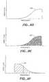
- Figs. 5A through 5Dare hypothetical graphical illustrations of the spectral envelope of a baseband signal and the spectral envelope of signals generated by translation of spectral components within the baseband signal.
- Fig. 5Ashows a hypothetical decoded baseband signal 900.
- Fig. 5Bshows spectral components of the baseband signal 905 translated to higher frequencies.
- Fig. 5Cshows the baseband signal components 910 translated multiple times to higher frequencies.
- Fig. 5Dshows a signal resulting from the combination of the translated components 915 and the baseband signal 920.
- the translation of spectral componentsmay create discontinuities in the phase of the regenerated components.
- the O-TDAC transform implementation described above, for example, as well as many other possible implementations,provides frequency-domain representations that are arranged in blocks of transform coefficients.
- the translated spectral componentsare also arranged in blocks. If spectral components regenerated by translation have phase discontinuities between successive blocks, audible artifacts in the output audio signal are likely to occur.
- the phase adjuster 815adjusts the phase of each regenerated spectral component to maintain a consistent or coherent phase.
- each of the regenerated spectral componentsis multiplied by the complex value eh j ⁇ , where ⁇ represents the frequency interval each respective spectral component is translated, expressed as the number of transform coefficients that correspond to that frequency interval. For example, if a spectral component is translated to the frequency of the adjacent component, the translation interval ⁇ is equal to one.
- Alternative implementationsmay require different phase adjustment techniques appropriate to the particular implementation of the synthesis filterbank 825.
- the translation processmay be adapted to match the regenerated components with harmonics of significant spectral components within the baseband signal.
- Two ways in which translation may be adaptedis by changing either the specific spectral components that are copied, or by changing the amount of translation. If an adaptive process is used, special care should be taken with regard to phase coherency if spectral components are arranged in blocks. If the regenerated spectral components are copied from different base components from block to block or if the amount of frequency translation is changed from block to block, it is very likely the regenerated components will not be phase coherent. It is possible to adapt the translation of spectral components but care must be taken to ensure the audibility of artifacts caused by phase incoherency is not significant.
- a system that employs either multiple-pass techniques or look-ahead techniquescould identify intervals during which translation could be adapted.
- Blocks representing intervals of an audio signal in which the regenerated spectral components are deemed to be inaudibleare usually good candidates for adapting the translation process.
- the blending filter 818generates a noise component for the translated spectral components using the noise-blending parameters received from the deformatter 805.
- the blending filter 818generates a noise signal, computes a noise-blending function using the noise-blending parameters and utilizes the noise-blending function to combine the noise signal with the translated spectral components.
- a noise signalcan be generated by any one of a variety of ways.
- a noise signalis produced by generating a sequence of random numbers having a distribution with zero mean and variance of one.
- the blending filter 818adjusts the noise signal by multiplying the noise signal by the noise-blending function. If a single noise-blending parameter is used, the noise-blending function generally should adjust the noise signal to have higher amplitude at higher frequencies. This follows from the assumptions discussed above that voice and natural musical instrument signals tend to contain more noise at higher frequencies. In a preferred implementation when spectral components are translated to higher frequencies, a noise-blending function has a maximum amplitude at the highest frequency and decays smoothly to a minimum value at the lowest frequency at which noise is blended.
- N kmax ⁇ k - k MIN k MAX - k MIN + B - 1 , 0 for k MIN ⁇ k ⁇ k MAX
- the value of Bvaries from zero to one, where one indicates a flat spectrum that is typical of a noise-like signal and zero indicates a spectral shape that is not flat and is typical of a tone-like signal.
- the value of the quotient in equation 1varies from zero to one as k increases from k MIN to k MAX . If B is equal to zero, the first term in the "max" function varies from negative one to zero; therefore, N( k ) will be equal to zero throughout the regenerated spectrum and no noise is added to regenerated spectral components.
- N( k )increases linearly from zero at the lowest regenerated frequency k MIN up to a value equal to one at the maximum regenerated frequency k MAX. If B has a value between zero and one, N( k ) is equal to zero from k MIN up to some frequency between k MIN and k MAX , and increases linearly for the remainder of the regenerated spectrum.
- the amplitude of the regenerated spectral componentsis adjusted by multiplying them with an inverse of the noise-blending function. The adjusted noise signal and the adjusted regenerated spectral components are combined.
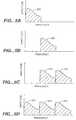
- Figs. 6A through 6Gare hypothetical graphical illustrations of the spectral envelopes of signals obtained by regenerating high-frequency components using both spectral translation and noise blending.
- Fig. 6Ashows a hypothetical input signal 410 to be transmitted.
- Fig. 6Bshows the baseband signal 420 produced by discarding high-frequency components.
- Fig. 6Cshows the regenerated high-frequency components 431, 432 and 433.
- Fig. 6Ddepicts a possible noise-blending function 440 that gives greater weight to noise components at higher frequencies.
- Fig. 6Eis a schematic illustration of a noise signal 445 that has been multiplied by the noise-blending function 440.
- Fig. 6Ashows a hypothetical input signal 410 to be transmitted.
- Fig. 6Bshows the baseband signal 420 produced by discarding high-frequency components.
- Fig. 6Cshows the regenerated high-frequency components 431, 432 and 433.
- Fig. 6Ddepicts a possible noise-blending function 440
- FIG. 6Fshows a signal 450 generated by multiplying the regenerated high-frequency components 431, 432 and 433 by the inverse of the noise-blending function 440.
- Fig. 6Gis a schematic illustration of a combined signal resulting from adding the adjusted noise signal 445 to the adjusted high-frequency components 450.
- Fig. 6Gis drawn to illustrate schematically that the high-frequency portion 430 contains a mixture of the translated high-frequency components 431, 432 and 433 and noise.
- the gain adjuster 820adjusts the amplitude of the regenerated signal according to the estimated spectral envelope information received from the deformatter 805.
- Fig. 6His a hypothetical illustration of the spectral envelope of signal shown in Fig. 6G after gain adjustment.
- the portion 510 of the signal containing a mixture of translated spectral components and noisehas been given a spectral envelope approximating that of the original signal 410 shown in Fig. 6A .
- Reproducing the spectral envelope on a fine scaleis generally unnecessary because the regenerated spectral components do not exactly reproduce the spectral components of the original signal.
- a translated harmonic seriesgenerally will not equal an harmonic series; therefore, it is generally impossible to ensure that the regenerated output signal is identical to the original input signal on a fine scale.
- the gain-adjusted regenerated spectral components provided by the gain adjuster 820are combined with the frequency-domain representation of the baseband signal received from the deformatter 805 to form a frequency-domain representation of a reconstructed signal. This may be done by adding the regenerated components to corresponding components of the baseband signal.
- Fig. 7shows a hypothetical reconstructed signal obtained by combining the baseband signal shown in Fig. 6B with the regenerated components shown in Fig. 6H .
- the synthesis filterbank 825transforms the frequency-domain representation into a time domain representation of the reconstructed signal.
- This filterbankcan be implemented in essentially any manner but it should be inverse to the filterbank 705 used in the transmitter 136.
- receiver 142uses O-TDAC synthesis that applies an inverse modified DCT.
- the width and location of the baseband signalcan be established in essentially any manner and can be varied dynamically according to input signal characteristics, for example.
- the transmitter 136generates a baseband signal by discarding multiple bands of spectral components, thereby creating gaps in the spectrum of the baseband signal. During spectral component regeneration, portions of the baseband signal are translated to regenerate the missing spectral components.
- the direction of translationcan also be varied.
- the transmitter 136discards spectral components at low frequencies to produce a baseband signal located at relatively higher frequencies.
- the receiver 142translates portions of the high-frequency baseband signal down to lower-frequency locations to regenerate the missing spectral components.
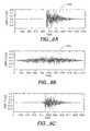
- Fig. 8Ashows the temporal shape of an audio signal 860.
- Fig. 8Bshows the temporal shape of a reconstructed output signal 870 produced by deriving a baseband signal from the signal 860 in Fig. 8A and regenerating discarded spectral components through a process of spectral component translation.
- the temporal shape of the reconstructed signal 870differs significantly from the temporal shape of the original signal 860. Changes in the temporal shape can have a significant effect on the perceived quality of a regenerated audio signal. Two methods for preserving the temporal envelope are discussed below.
- the transmitter 136determines the temporal envelope of the input audio signal in the time domain and the receiver 142 restores the same or substantially the same temporal envelope to the reconstructed signal in the time domain.
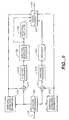
- Fig. 9shows a block diagram of one implementation of the transmitter 136 in a communication system that provides temporal envelope control using a time-domain technique.
- the analysis filterbank 205receives an input signal from path 115 and divides the signal into multiple frequency subband signals. The figure illustrates only two subbands for illustrative clarity; however, the analysis filterbank 205 may divide the input signal into any integer number of subbands that is greater than one.
- the analysis filterbank 205may be implemented in essentially any manner such as one or more Quadrature Mirror Filters (QMF) connected in cascade or, preferably, by a pseudo-QMF technique that can divide an input signal into any integer number of subbands in one filter stage. Additional information about the pseudo-QMF technique may be obtained from Vaidyanathan, "Multirate Systems and Filter Banks," Prentice Hall, New Jersey, 1993, pp. 354-373 .
- QMFQuadrature Mirror Filters
- the subband signalsare used to form the baseband signal.
- the remaining subband signalscontain the spectral components of the input signal that are discarded.
- the baseband signalis formed from one subband signal representing the lowest-frequency spectral components of the input signal, but this is not necessary in principle.
- the analysis filterbank 205divides the input signal into four subbands having ranges of frequencies as shown above in Table I. The lowest-frequency subband is used to form the baseband signal.
- the analysis filterbank 205passes the lower-frequency subband signal as the baseband signal to the temporal envelope estimator 213 and the modulator 214.
- the temporal envelope estimator 213provides an estimated temporal envelope of the baseband signal to the modulator 214 and to the signal formatter 225.
- baseband signal spectral componentsthat are below about 500 Hz are either excluded from the process that estimates the temporal envelope or are attenuated so that they do not have any significant effect on the shape of the estimated temporal envelope. This may be accomplished by applying an appropriate high-pass filter to the signal that is analyzed by the temporal envelope estimator 213.
- the modulator 214divides the amplitude of the baseband signal by the estimated temporal envelope and passes to the analysis filterbank 215 a representation of the baseband signal that is flattened temporally.
- the analysis filterbank 215generates a frequency-domain representation of the flattened baseband signal, which is passed to the encoder 220 for encoding.
- the analysis filterbank 215, as well as the analysis filterbank 212 discussed below,may be implemented by essentially any time-domain-to-frequency-domain transform; however, a transform like the O-TDAC transform that implements a critically-sampled filterbank is generally preferred.
- the encoder 220is optional; however, its use is preferred because encoding can generally be used to reduce the information requirements of the flattened baseband signal.
- the flattened baseband signalis passed to the signal formatter 225.
- the analysis filterbank 205passes the higher-frequency subband signal to the temporal envelope estimator 210 and the modulator 211.
- the temporal envelope estimator 210provides an estimated temporal envelope of the higher-frequency subband signal to the modulator 211 and to the output signal formatter 225.
- the modulator 211divides the amplitude of the higher-frequency subband signal by the estimated temporal envelope and passes to the analysis filterbank 212 a representation of the higher-frequency subband signal that is flattened temporally.
- the analysis filterbank 212generates a frequency-domain representation of the flattened higher-frequency subband signal.
- the spectral envelope estimator 720 and the spectral analyzer 722provide an estimated spectral envelope and one or more noise-blending parameters, respectively, for the higher-frequency subband signal in essentially the same manner as that described above, and pass this information to the signal formatter 225.
- the signal formatter 225provides an output signal along communication channel 140 by assembling a representation of the flattened baseband signal, the estimated temporal envelopes of the baseband signal and the higher-frequency subband signal, the estimated spectral envelope, and the one or more noise-blending parameters into the output signal.
- the individual signals and informationare assembled into a signal having a form that is suitable for transmission or storage using essentially any desired formatting technique as described above for the signal formatter 725.
- the temporal envelope estimators 210 and 213may be implemented in wide variety of ways. In one implementation, each of these estimators processes a subband signal that is divided into blocks of subband signal samples. These blocks of subband signal samples are also processed by either the analysis filterbank 212 or 215. In many practical implementations, the blocks are arranged to contain a number of samples that is a power of two and is greater than 256 samples. Such a block size is generally preferred to improve the efficiency and the frequency resolution of the transforms used to implement the analysis filterbanks 212 and 215. The length of the blocks may also be adapted in response to input signal characteristics such as the occurrence or absence of large transients. Each block is further divided into groups of 256 samples for temporal envelope estimation. The size of the groups is chosen to balance a tradeoff between the accuracy of the estimate and the amount of information required to convey the estimate in the output signal.
- the temporal envelope estimatorcalculates the power of the samples in each group of subband signal samples.
- the set of power values for the block of subband signal samplesis the estimated temporal envelope for that block.
- the temporal envelope estimatorcalculates the mean value of the subband signal sample magnitudes in each group.
- the set of means for the blockis the estimated temporal envelope for that block.
- the set of values in the estimated envelopemay be encoded in a variety of ways.
- the envelope for each blockis represented by an initial value for the first group of samples in the block and a set of differential values that express the relative values for subsequent groups.
- either differential or absolute codesare used in an adaptive manner to reduce the amount of information required to convey the values.
- Fig. 10shows a block diagram of one implementation of the receiver 142 in a communication system that provides temporal envelope control using a time-domain technique.
- the deformatter 265receives a signal from communication channel 140 and obtains from this signal a representation of a flattened baseband signal, estimated temporal envelopes of the baseband signal and a higher-frequency subband signal, an estimated spectral envelope and one or more noise-blending parameters.
- the decoder 267is optional but should be used to reverse the effects of any encoding performed in the transmitter 136 to obtain a frequency-domain representation of the flattened baseband signal.
- the synthesis filterbank 280receives the frequency-domain representation of the flattened baseband signal and generates a time-domain representation using a technique that is inverse to that used by the analysis filterbank 215 in the transmitter 136.
- the modulator 281receives the estimated temporal envelope of the baseband signal from the deformatter 265, and uses this estimated envelope to modulate the flattened baseband signal received from the synthesis filterbank 280. This modulation provides a temporal shape that is substantially the same as the temporal shape of the original baseband signal before it was flattened by the modulator 214 in the transmitter 136.
- the signal processor 808receives the frequency-domain representation of the flattened baseband signal, the estimated spectral envelope and the one or more noise-blending parameters from the deformatter 265, and regenerates spectral components in the same manner as that discussed above for the signal processor 808 shown in Fig. 4 .
- the regenerated spectral componentsare passed to the synthesis filterbank 283, which generates a time-domain representation using a technique that is inverse to that used by the analysis filterbanks 212 and 215 in the transmitter 136.
- the modulator 284receives the estimated temporal envelope of the higher-frequency subband signal from the deformatter 265, and uses this estimated envelope to modulate the regenerated spectral components signal received from the synthesis filterbank 283. This modulation provides a temporal shape that is substantially the same as the temporal shape of the original higher-frequency subband signal before it was flattened by the modulator 211 in the transmitter 136.
- the modulated baseband signal and the modulated higher-frequency subband signalare combined to form a reconstructed signal, which is passed to the synthesis filterbank 287.
- the synthesis filterbank 287uses a technique inverse to that used by the analysis filterbank 205 in the transmitter 136 to provide along path 145 an output signal that is perceptually indistinguishable or nearly indistinguishable from the original input signal received from path 115 by the transmitter 136.
- the transmitter 136determines the temporal envelope of the input audio signal in the frequency domain and the receiver 142 restores the same or substantially the same temporal envelope to the reconstructed signal in the frequency domain.
- Fig. 11shows a block diagram of one implementation of the transmitter 136 in a communication system that provides temporal envelope control using a frequency-domain technique.
- the implementation of this transmitteris very similar to the implementation of the transmitter shown in Fig. 2 .
- the principal differenceis the temporal envelope estimator 707.
- the other componentsare not discussed here in detail because their operation is essentially the same as that described above in connection with Fig. 2 .
- the temporal envelope estimator 707receives from the analysis filterbank 705 a frequency-domain representation of the input signal, which it analyzes to derive an estimate of the temporal envelope of the input signal.
- spectral components that are below about 500 Hzare either excluded from the frequency-domain representation or are attenuated so that they do not have any significant effect on the process that estimates the temporal envelope.
- the temporal envelope estimator 707obtains a frequency-domain representation of a temporally-flattened version of the input signal by deconvolving a frequency-domain representation of the estimated temporal envelope and the frequency-domain representation of the input signal.
- This deconvolutionmay be done by convolving the frequency-domain representation of the input signal with an inverse of the frequency-domain representation of the estimated temporal envelope.
- the frequency-domain representation of a temporally-flattened version of the input signalis passed to the filter 715, the baseband signal analyzer 710, and the spectral envelope estimator 720.
- a description of the frequency-domain representation of the estimated temporal envelopeis passed to the signal formatter 725 for assembly into the output signal that is passed along the communication channel 140.
- the signal y ( t )is the audio signal that the transmitter 136 receives from path 115.
- the analysis filterbank 705provides the frequency-domain representation Y [ k ] of the signal y ( t ).
- the temporal envelope estimator 707obtains an estimate of the frequency-domain representation H [ k ] of the signal's temporal envelope h ( t ) by solving a set of equations derived from an autoregressive moving average (ARMA) model of Y [ k ] and X [ k ].
- ARMAautoregressive moving average
- ARMA modelsmay be obtained from Proakis and Manolakis, "Digital Signal Processing: Principles, Algorithms and Application, MacMillan Publishing Co., New York, 1988. See especially pp. 818-821 .
- the filterbank 705applies a transform to blocks of samples representing the signal y ( t ) to provide the frequency-domain representation Y [ k ] arranged in blocks of transform coefficients.
- Each block of transform coefficientsexpresses a short-time spectrum of the signal of the signal y ( t ).
- the frequency-domain representation X [ k ]is also arranged in blocks.
- Each block of coefficients in the frequency-domain representation X [ k ]represents a block of samples for the temporally-flat signal x ( t ) that is assumed to be wide sense stationary (WSS). It is also assumed the coefficients in each block of the X [ k ] representation are independently distributed (ID).
- the temporal envelope estimator 707receives a frequency-domain representation Y [ k ] of an input signal y ( t ) and calculates the autocorrelation sequence R XX [ m ] for - L ⁇ m ⁇ L . These values are used to construct the matrix shown in equation 8. The matrix is then inverted to solve for the coefficients a i . Because the matrix in equation 8 is Toeplitz, it can be inverted by the Levinson-Durbin algorithm. For information, see Proakis and Manolakis, pp. 458-462.
- the set of equations obtained by inverting the matrixcannot be solved directly because the variance ⁇ 2 X of X [ k ] is not known; however, the set of equations can be solved for some arbitrary variance such as the value one. Once solved for this arbitrary value, the set of equations yields a set of unnormalized coefficients ⁇ a ' 0 , ..., a ' L ⁇ . These coefficients are unnormalized because the equations were solved for an arbitrary variance.
- the set of normalized coefficients ⁇ 1, a 1 , ..., a L ⁇represents the zeroes of a flattening filter FF that can be convolved with a frequency-domain representation Y [ k ] of an input signal y ( t ) to obtain a frequency-domain representation X [ k ] of a temporally-flattened version x ( t ) of the input signal.
- the set of normalized coefficientsalso represents the poles of a reconstruction filter FR that can be convolved with the frequency-domain representation X [ k ] of a temporally-flat signal x ( t ) to obtain a frequency-domain representation of that flat signal having a modified temporal shape substantially equal to the temporal envelope of the input signal y ( t ).
- the temporal envelope estimator 707convolves the flattening filter FF with the frequency-domain representation Y [ k ] received from the filterbank 705 and passes the temporally-flattened result to the filter 715, the baseband signal analyzer 710, and the spectral envelope estimator 720.
- a description of the coefficients in flattening filter FFis passed to the signal formatter 725 for assembly into the output signal passed along path 140.
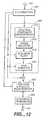
- Fig. 12shows a block diagram of one implementation of the receiver 142 in a communication system that provides temporal envelope control using a frequency-domain technique.
- the implementation of this receiveris very similar to the implementation of the receiver shown in Fig. 4 .
- the principal differenceis the temporal envelope regenerator 807.
- the other componentsare not discussed here in detail because their operation is essentially the same as that described above in connection with Fig. 4 .
- the temporal envelope regenerator 807receives from the deformatter 805 a description of an estimated temporal envelope, which is convolved with a frequency-domain representation of a reconstructed signal.
- the result obtained from the convolutionis passed to the synthesis filterbank 825, which provides along path 145 an output signal that is perceptually indistinguishable or nearly indistinguishable from the original input signal received from path 115 by the transmitter 136.
- the temporal envelope regenerator 807may be implemented in a number of ways.
- the deformatter 805provides a set of coefficients that represent the poles of a reconstruction filter FR , which is convolved with the frequency-domain representation of the reconstructed signal.
- the spectral components of the frequency-domain representation received from the filterbank 705are grouped into frequency subbands.
- the set of subbands shown in Table Iis one suitable example.
- a flattening filter FFis derived for each subband and convolved with the frequency-domain representation of each subband to temporally flatten it.
- the signal formatter 725assembles into the output signal an identification of the estimated temporal envelope for each subband.
- the receiver 142receives the envelope identification for each subband, obtains an appropriate regeneration filter FR for each subband, and convolves it with a frequency-domain representation of the corresponding subband in the reconstructed signal.
- multiple sets of coefficients ⁇ C i ⁇ jare stored in a table.
- Coefficients ⁇ 1, a 1 , ..., a L ⁇ for flattening filter FFare calculated for an input signal, and the calculated coefficients are compared with each of the multiple sets of coefficients stored in the table.
- the set ⁇ C i ⁇ j in the table that is deemed to be closest to the calculated coefficientsis selected and used to flatten the input signal.
- An identification of the set ⁇ C ⁇ ⁇ j that is selected from the tableis passed to the signal formatter 725 to be assembled into the output signal.
- the receiver 142receives the identification of the set ⁇ C i ⁇ j , consults a table of stored coefficient sets to obtain the appropriate set of coefficients ⁇ C i ⁇ j , derives a regeneration filter FR that corresponds to the coefficients, and convolves the filter with a frequency-domain representation of the reconstructed signal. This alternative may also be applied to subbands as discussed above.
- One way in which a set of coefficients in the table may be selectedis to define a target point in an L -dimensional space having Euclidean coordinates equal to the calculated coefficients ( a 1 , ..., a L ) for the input signal or subband of the input signal.
- Each of the sets stored in the tablealso defines a respective point in the L -dimensional space.
- the set stored in the table whose associated point has the shortest Euclidean distance to the target pointis deemed to be closest to the calculated coefficients. If the table stores 256 sets of coefficients, for example, an eight-bit number could be passed to the signal formatter 725 to identify the selected set of coefficients.
- the present inventionmay be implemented in a wide variety of ways. Analog and digital technologies may be used as desired. Various aspects may be implemented by discrete electrical components, integrated circuits, programmable logic arrays, ASICs and other types of electronic components, and by devices that execute programs of instructions, for example. Programs of instructions may be conveyed by essentially any device-readable media such as magnetic and optical storage media, read-only memory and programmable memory.
Landscapes
- Engineering & Computer Science (AREA)
- Physics & Mathematics (AREA)
- Multimedia (AREA)
- Computational Linguistics (AREA)
- Signal Processing (AREA)
- Health & Medical Sciences (AREA)
- Audiology, Speech & Language Pathology (AREA)
- Human Computer Interaction (AREA)
- Acoustics & Sound (AREA)
- Spectroscopy & Molecular Physics (AREA)
- Quality & Reliability (AREA)
- Compression, Expansion, Code Conversion, And Decoders (AREA)
- Electrically Operated Instructional Devices (AREA)
- Stereophonic System (AREA)
- Signal Processing Not Specific To The Method Of Recording And Reproducing (AREA)
- Signal Processing For Digital Recording And Reproducing (AREA)
- Tone Control, Compression And Expansion, Limiting Amplitude (AREA)
- Measurement And Recording Of Electrical Phenomena And Electrical Characteristics Of The Living Body (AREA)
- Reduction Or Emphasis Of Bandwidth Of Signals (AREA)
- Ceramic Products (AREA)
- Superconductors And Manufacturing Methods Therefor (AREA)
Abstract
Description
- The present invention relates generally to the transmission and recording of audio signals. More particularly, the present invention provides for a reduction of information required to transmit or store a given audio signal while maintaining a given level of perceived quality in the output signal.
- Many communications systems face the problem that the demand for information transmission and storage capacity often exceeds the available capacity. As a result there is considerable interest among those in the fields of broadcasting and recording to reduce the amount of information required to transmit or record an audio signal intended for human perception without degrading its subjective quality. Similarly there is a need to improve the quality of the output signal for a given bandwidth or storage capacity.
- Two principle considerations drive the design of systems intended for audio transmission and storage: the need to reduce information requirements and the need to ensure a specified level of perceptual quality in the output signal. These two considerations conflict in that reducing the quantity of information transmitted can reduce the perceived quality of the output signal. While objective constraints such as data rate are usually imposed by the communications system itself, subjective perceptual requirements are usually dictated by the application.
- Traditional methods for reducing information requirements involve transmitting or recording only a selected portion of the input signal, with the remainder being discarded. Preferably, only that portion deemed to be either redundant or perceptually irrelevant is discarded. If additional reduction is required, preferably only a portion of the signal deemed to have the least perceptual significance is discarded.
- Speech applications that emphasize intelligibility over fidelity, such as speech coding, may transmit or record only a portion of a signal, referred to herein as a "baseband signal", which contains only the perceptually most relevant portions of the signal's frequency spectrum. A receiver can regenerate the omitted portion of the voice signal from information contained within that baseband signal. The regenerated signal generally is not perceptually identical to the original, but for many applications an approximate reproduction is sufficient. On the other hand, applications designed to achieve a high degree of fidelity, such as high-quality music applications, generally require a higher quality output signal. To obtain a higher quality output signal, it is generally necessary to transmit a greater amount of information or to utilize a more sophisticated method of generating the output signal.
- One technique used in connection with speech signal decoding is known as high frequency regeneration ("HFR"). A baseband signal containing only low-frequency components of a signal is transmitted or stored. A receiver regenerates the omitted high-frequency components based on the contents of the received baseband signal and combines the baseband signal with the regenerated high-frequency components to produce an output signal. Although the regenerated high-frequency components are generally not identical to the high-frequency components in the original signal, this technique can produce an output signal that is more satisfactory than other techniques that do not use HFR. Numerous variations of this technique have been developed in the area of speech encoding and decoding. Three common methods used for HFR are spectral folding, spectral translation, and rectification. A description of these techniques can be found inMakhoul and Berouti, "High-Frequency Regeneration in Speech Coding Systems", ICASSP 1979 IEEE International Conf. on Acoust., Speech and Signal Proc., April 2-4, 1979.
- Although simple to implement, these HFR techniques are usually not suitable for high quality reproduction systems such as those used for high quality music. Spectral folding and spectral translation can produce undesirable background tones. Rectification tends to produce results that are perceived to be harsh. The inventors have noted that in many cases where these techniques have produced unsatisfactory results, the techniques were used in bandlimited speech coders where HFR was restricted to the translation of components below 5 kHz.
- The inventors have also noted two other problems that can arise from the use of HFR techniques. The first problem is related to the tone and noise characteristics of signals, and the second problem is related to the temporal shape or envelope of regenerated signals. Many natural signals contain a noise component that increases in magnitude as a function of frequency. A few known HFR techniques such as that described in
WO 00/45379 - A number of more sophisticated HFR techniques have been developed that offer improved results; however, these techniques tend to be either speech specific, relying on characteristics of speech that are not suitable for music and other forms of audio, or require extensive computational resources that cannot be implemented economically.
- It is an object of the present invention to provide for the processing of audio signals to reduce the quantity of information required to represent a signal during transmission or storage while maintaining the perceived quality of the signal. Although the present invention is particularly directed toward the reproduction of music signals, it is also applicable to a wide range of audio signals including voice.
- This object is achieved with a method and an apparatus as claimed in
claims 1 and 6, respectively, and a storage medium according to claim 11. Preferred embodiments of the invention are defined in the dependent claims. - Other aspects of the present invention are described below and set forth in the claims.
- The various features of the present invention and its preferred implementations may be better understood by referring to the following discussion and the accompanying drawings in which like reference numerals refer to like elements in the several figures. The contents of the following discussion and the drawings are set forth as examples only and should not be understood to represent limitations upon the scope of the present invention.
Fig. 1 illustrates major components in a communications system.Fig. 2 is a block diagram of a transmitter.Figs. 3A and 3B are hypothetical graphical illustrations of an audio signal and a corresponding baseband signal.Fig. 4 is a block diagram of a receiver.Figs. 5A-5D are hypothetical graphical illustrations of a baseband signal and signals generated by translation of the baseband signal.Figs. 6A-6G are hypothetical graphical illustrations of signals obtained by regenerating high-frequency components using both spectral translation and noise blending.Fig. 6H is an illustration of the signal inFig. 6G after gain adjustment.Fig. 7 is an illustration of the baseband signal shown inFig. 6B combined with the regenerated signal shown inFig. 6H .Fig. 8A is an illustration of a signal's temporal shape.Fig. 8B shows the temporal shape of an output signal that is produced by deriving a baseband signal from the signal inFig. 8A and regenerating the signal through a process of spectral translation.Fig. 8C shows the temporal shape of the signal inFig. 8B after temporal envelope control has been performed.Fig. 9 is a block diagram of a transmitter that provides information needed for temporal envelope control using time-domain techniques.Fig. 10 is a block diagram of a receiver that provides temporal envelope control using time-domain techniques.Fig. 11 is a block diagram of a transmitter that provides information needed for temporal envelope control using frequency-domain techniques.Fig. 12 is a block diagram of a receiver that provides temporal envelope control using frequency-domain techniques.Fig. 1 illustrates major components in one example of a communications system. Aninformation source 112 generates an audio signal alongpath 115 that represents essentially any type of audio information such as speech or music. Atransmitter 136 receives the audio signal frompath 115 and processes the information into a form that is suitable for transmission through thechannel 140. Thetransmitter 136 may prepare the signal to match the physical characteristics of thechannel 140. Thechannel 140 may be a transmission path such as electrical wires or optical fibers, or it may be a wireless communication path through space. Thechannel 140 may also include a storage device that records the signal on a storage medium such as a magnetic tape or disk, or an optical disc for later use by areceiver 142. Thereceiver 142 may perform a variety of signal processing functions such as demodulation or decoding of the signal received from thechannel 140. The output of thereceiver 142 is passed along apath 145 to atransducer 147, which converts it into anoutput signal 152 that is suitable for the user. In a conventional audio playback system, for example, loudspeakers serve as transducers to convert electrical signals into acoustic signals.- Communication systems, which are restricted to transmitting over a channel that has a limited bandwidth or recording on a medium that has limited capacity, encounter problems when the demand for information exceeds this available bandwidth or capacity. As a result there is a continuing need in the fields of broadcasting and recording to reduce the amount of information required to transmit or record an audio signal intended for human perception without degrading its subjective quality. Similarly there is a need to improve the quality of the output signal for a given transmission bandwidth or storage capacity.
- A technique used in connection with speech coding is known as high-frequency regeneration ("HFR"). Only a baseband signal containing low-frequency components of a speech signal are transmitted or stored. The
receiver 142 regenerates the omitted high-frequency components based on the contents of the received baseband signal and combines the baseband signal with the regenerated high-frequency components to produce an output signal. In general, however, known HFR techniques produce regenerated high-frequency components that are easily distinguishable from the high-frequency components in the original signal. The present invention provides an improved technique for spectral component regeneration that produces regenerated spectral components perceptually more similar to corresponding spectral components in the original signal than is provided by other known techniques. It is important to note that although the techniques described herein are sometimes referred to as high-frequency regeneration, the present invention is not limited to the regeneration of high-frequency components of a signal. The techniques described below may also be utilized to regenerate spectral components in any part of the spectrum. Fig. 2 is a block diagram of thetransmitter 136 according to one aspect of the present invention. An input audio signal is received frompath 115 and processed by ananalysis filterbank 705 to obtain a frequency-domain representation of the input signal. Abaseband signal analyzer 710 determines which spectral components of the input signal are to be discarded. Afilter 715 removes the spectral components to be discarded to produce a baseband signal consisting of the remaining spectral components. Aspectral envelope estimator 720 obtains an estimate of the input signal's spectral envelope. Aspectral analyzer 722 analyzes the estimated spectral envelope to determine noise-blending parameters for the signal. Asignal formatter 725 combines the estimated spectral envelope information, the noise-blending parameters, and the baseband signal into an output signal having a form suitable for transmission or storage.- The
analysis filterbank 705 may be implemented by essentially any time-domain to frequency-domain transform. The transform used in a preferred implementation of the present invention is described inPrincen, Johnson and Bradley, "Subband/Transform Coding Using Filter Bank Designs Based on Time Domain Aliasing Cancellation," ICASSP 1987 Conf. Proc., May 1987, pp. 2161-64. This transform is the time-domain equivalent of an oddly-stacked critically sampled single-sideband analysis-synthesis system with time-domain aliasing cancellation and is referred to herein as "O-TDAC". - According to the O-TDAC technique, an audio signal is sampled, quantized and grouped into a series of overlapped time-domain signal sample blocks. Each sample block is weighted by an analysis window function. This is equivalent to a sample-by-sample multiplication of the signal sample block. The O-TDAC technique applies a modified Discrete Cosine Transform ("DCT") to the weighted time-domain signal sample blocks to produce sets of transform coefficients, referred to herein as "transform blocks". To achieve critical sampling, the technique retains only half of the spectral coefficients prior to transmission or storage. Unfortunately, the retention of only half of the spectral coefficients causes a complementary inverse transform to generate time-domain aliasing components. The O-TDAC technique can cancel the aliasing and accurately recover the input signal. The length of the blocks may be varied in response to signal characteristics using techniques that are known in the art; however, care should be taken with respect to phase coherency for reasons that are discussed below. Additional details of the O-TDAC technique may be obtained by referring to
U.S. Patent 5,394,473 . - To recover the original input signal blocks from the transform blocks, the O-TDAC technique utilizes an inverse modified DCT. The signal blocks produced by the inverse transform are weighted by a synthesis window function, overlapped and added to recreate the input signal. To cancel the time-domain aliasing and accurately recover the input signal, the analysis and synthesis windows must be designed to meet strict criteria.
- In one preferred implementation of a system for transmitting or recording an input digital signal sampled at a rate of 44.1 kilosamples/second, the spectral components obtained from the
analysis filterbank 705 are divided into four subbands having ranges of frequencies as shown in Table I.Table I Band Frequency Range (kHz) 0 0.0 to 5.5 1 5.5 to 11.0 2 11.0 to 16.5 3 16.5 to 22.0 - The
baseband signal analyzer 710 selects which spectral components to discard and which spectral components to retain for the baseband signal. This selection can vary depending on input signal characteristics or it can remain fixed according to the needs of an application; however, the inventors have determined empirically that the perceived quality of an audio signal deteriorates if one or more of the signal's fundamental frequencies are discarded. It is therefore preferable to preserve those portions of the spectrum that contain the signal's fundamental frequencies. Because the fundamental frequencies of voice and most natural musical instruments are generally no higher than about 5 kHz, a preferred implementation of thetransmitter 136 intended for music applications uses a fixed cutoff frequency at or around 5 kHz and discards all spectral components above that frequency. In the case of a fixed cutoff frequency, the baseband signal analyzer need not do anything more than provide the fixed cutoff frequency to thefilter 715 and thespectral analyzer 722. In an alternative implementation, thebaseband signal analyzer 710 is eliminated and thefilter 715 and thespectral analyzer 722 operate according to the fixed cutoff frequency. In the subband structure shown above in Table I, for example, the spectral components inonly subband 0 are retained for the baseband signal. This choice is also suitable because the human ear cannot easily distinguish differences in pitch above 5 kHz and therefore cannot easily discern inaccuracies in regenerated components above this frequency. - The choice of cutoff frequency affects the bandwidth of the baseband signal, which in turn influences a tradeoff between the information capacity requirements of the output signal generated by the
transmitter 136 and the perceived quality of the signal reconstructed by thereceiver 142. The perceived quality of the signal reconstructed by thereceiver 142 is influenced by three factors that are discussed in the following paragraphs. - The first factor is the accuracy of the baseband signal representation that is transmitted or stored. Generally, if the bandwidth of a baseband signal is held constant, the perceived quality of a reconstructed signal will increase as the accuracy of the baseband signal representation is increased. Inaccuracies represent noise that will be audible in the reconstructed signal if the inaccuracies are large enough. The noise will degrade both the perceived quality of the baseband signal and the spectral components that are regenerated from the baseband signal. In an exemplary implementation, the baseband signal representation is a set of frequency-domain transform coefficients. The accuracy of this representation is controlled by the number of bits that are used to express each transform coefficient. Coding techniques can be used to convey a given level of accuracy with fewer bits; however, a basic tradeoff between baseband signal accuracy and information capacity requirements exists for any given coding technique.
- The second factor is the bandwidth of the baseband signal that is transmitted or stored. Generally, if the accuracy of the baseband signal representation is held constant, the perceived quality of a reconstructed signal will increase as the bandwidth of the baseband signal is increased. The use of wider bandwidth baseband signals allows the
receiver 142 to confine regenerated spectral components to higher frequencies where the human auditory system is less sensitive to differences in temporal and spectral shape. In the exemplary implementation mentioned above, the bandwidth of the baseband signal is controlled by the number of transform coefficients in the representation. Coding techniques can be used to convey a given number of coefficients with fewer bits; however, a basic tradeoff between baseband signal bandwidth and information capacity requirements exists for any given coding technique. - The third factor is the information capacity that is required to transmit or store the baseband signal representation. If the information capacity requirement is held constant, the baseband signal accuracy will vary inversely with the bandwidth of the baseband signal. The needs of an application will generally dictate a particular information capacity requirement for the output signal that is generated by the
transmitter 136. This capacity must be allocated to various portions of the output signal such as a baseband signal representation and an estimated spectral envelope. The allocation must balance the needs of a number of conflicting interests that are well known for communication systems. Within this allocation, the bandwidth of the baseband signal should be chosen to balance a tradeoff with coding accuracy to optimize the perceived quality of the reconstructed signal. - The
spectral envelope estimator 720 analyzes the audio signal to extract information regarding the signal's spectral envelope. If available information capacity permits, an implementation of thetransmitter 136 preferably obtains an estimate of a signal's spectral envelope by dividing the signal's spectrum into frequency bands with bandwidths approximating the human ear's critical bands, and extracting information regarding the signal magnitude in each band. In most applications having limited information capacity, however, it is preferable to divide the spectrum into a smaller number of subbands such as the arrangement shown above in Table I. Other variations may be used such as calculating a power spectral density, or extracting the average or maximum amplitude in each band. More sophisticated techniques can provide higher quality in the output signal but generally require greater computational resources. The choice of method used to obtain an estimated spectral envelope generally has practical implications because it generally affects the perceived quality of the communication system; however, the choice of method is not critical in principle. Essentially any technique may be used as desired. - In one implementation using the subband structure shown in Table I, the
spectral envelope estimator 720 obtains an estimate of the spectral envelope only forsubbands - The
spectral analyzer 722 analyzes the estimated spectral envelope received from thespectral envelope estimator 720 and information from thebaseband signal analyzer 710, which identifies the spectral components to be discarded from a baseband signal, and calculates one or more noise-blending parameters to be used by thereceiver 142 to generate a noise component for translated spectral components. A preferred implementation minimizes data rate requirements by computing and transmitting a single noise-blending parameter to be applied by thereceiver 142 to all translated components. Noise-blending parameters can be calculated by any one of a number of different methods. A preferred method derives a single noise-blending parameter equal to a spectral flatness measure that is calculated from the ratio of the geometric mean to the arithmetic mean of the short-time power spectrum. The ratio gives a rough indication of the flatness of the spectrum. A higher spectral flatness measure, which indicates a flatter spectrum, also indicates a higher noise-blending level is appropriate. - In an alternative implementation of the
transmitter 136, the spectral components are grouped into multiple subbands such as those shown in Table I, and thetransmitter 136 transmits a noise-blending parameter for each subband. This more accurately defines the amount of noise to be mixed with the translated frequency content but it also requires a higher data rate to transmit the additional noise-blending parameters. - The
filter 715 receives information from thebaseband signal analyzer 710, which identifies the spectral components that are selected to be discarded from a baseband signal, and eliminates the selected frequency components to obtain a frequency-domain representation of the baseband signal for transmission or storage.Figs. 3A and 3B are hypothetical graphical illustrations of an audio signal and a corresponding baseband signal.Fig. 3A shows the spectral envelope of a frequency-domain representation 600 of a hypothetical audio signal.Fig. 3B shows the spectral envelope of the baseband signal 610 that remains after the audio signal is processed to eliminate selected high-frequency components. - The
filter 715 may be implemented in essentially any manner that effectively removes the frequency components that are selected for discarding. In one implementation, thefilter 715 applies a frequency-domain window function to the frequency-domain representation of the input audio signal. The shape of the window function is selected to provide an appropriate trade off between frequency selectivity and attenuation against time-domain effects in the output audio signal that is ultimately generated by thereceiver 142. - The
signal formatter 725 generates an output signal alongcommunication channel 140 by combining the estimated spectral envelope information, the one or more noise-blending parameters, and a representation of the baseband signal into an output signal having a form suitable for transmission or storage. The individual signals may be combined in essentially any manner. In many applications, theformatter 725 multiplexes the individual signals into a serial bit stream with appropriate synchronization patterns, error detection and correction codes, and other information that is pertinent either to transmission or storage operations or to the application in which the audio information is used. Thesignal formatter 725 may also encode all or portions of the output signal to reduce information capacity requirements, to provide security, or to put the output signal into a form that facilitates subsequent usage. Fig. 4 is a block diagram of thereceiver 142 according to one aspect of the present invention. Adeformatter 805 receives a signal from thecommunication channel 140 and obtains from this signal a baseband signal, estimated spectral envelope information and one or more noise-blending parameters. These elements of information are transmitted to asignal processor 808 that comprises aspectral regenerator 810, aphase adjuster 815, a blendingfilter 818 and again adjuster 820. Thespectral component regenerator 810 determines which spectral components are missing from the baseband signal and regenerates them by translating all or at least some spectral components of the baseband signal to the locations of the missing spectral components. The translated components are passed to thephase adjuster 815, which adjusts the phase of one or more spectral components within the combined signal to ensure phase coherency. The blendingfilter 818 adds one or more noise components to the translated components according to the one or more noise-blending parameters received with the baseband signal. Thegain adjuster 820 adjusts the amplitude of spectral components in the regenerated signal according to the estimated spectral envelope information received with the baseband signal. The translated and adjusted spectral components are combined with the baseband signal to produce a frequency-domain representation of the output signal. Asynthesis filterbank 825 processes the signal to obtain a time-domain representation of the output signal, which is passed alongpath 145.- The
deformatter 805 processes the signal received fromcommunication channel 140 in a manner that is complementary to the formatting process provided by thesignal formatter 725. In many applications, thedeformatter 805 receives a serial bit stream from thechannel 140, uses synchronization patterns within the bit stream to synchronize its processing, uses error correction and detection codes to identify and rectify errors that were introduced into the bit stream during transmission or storage, and operates as a demultiplexer to extract a representation of the baseband signal, the estimated spectral envelope information, one or more noise-blending parameters, and any other information that may be pertinent to the application. Thedeformatter 805 may also decode all or portions of the serial bit stream to reverse the effects of any coding provided by thetransmitter 136. A frequency-domain representation of the baseband signal is passed to thespectral component regenerator 810, the noise-blending parameters are passed to the blendingfilter 818, and the spectral envelope information is passed to thegain adjuster 820. - The
spectral component regenerator 810 regenerates missing spectral components by copying or translating all or at least some of the spectral components of the baseband signal to the locations of the missing components of the signal. Spectral components may be copied into more than one interval of frequencies, thereby allowing an output signal to be generated with a bandwidth greater than twice the bandwidth of the baseband signal. - In an implementation of the
receiver 142 that uses only subbands 0 and 1 shown above in Table I, the baseband signal contains no spectral components above a cutoff frequency at or about 5.5 kHz. Spectral components of the baseband signal are copied or translated to a range of frequencies from about 5.5 kHz to about 11.0 kHz. If a 16.5 kHz bandwidth is desired, for example, the spectral components of the baseband signal can also be translated into ranges of frequencies from about 11.0 kHz to about 16.5 kHz. Generally, the spectral components are translated into non-overlapping frequency ranges such that no gap exists in the spectrum including the baseband signal and all copied spectral components; however, this feature is not essential. Spectral components may be translated into overlapping frequency ranges and/or into frequency ranges with gaps in the spectrum in essentially any manner as desired. - The choice of which spectral components should be copied can be varied to suit the particular application. For example, spectral components that are copied need not start at the lower edge of the baseband and need not end at the upper edge of the baseband. The perceived quality of the signal reconstructed by the
receiver 142 can sometimes be improved by excluding fundamental frequencies of voice and instruments and copying only harmonics. This aspect is incorporated into one implementation by excluding from translation those baseband spectral components that are below about 1 kHz. Referring to the subband structure shown above in Table I as an example, only spectral components from about 1 kHz to about 5.5 kHz are translated. - If the bandwidth of all spectral components to be regenerated is wider than the bandwidth of the baseband spectral components to be copied, the baseband spectral components may be copied in a circular manner starting with the lowest frequency component up to the highest frequency component and, if necessary, wrapping around and continuing with the lowest frequency component. For example, referring to the subband structure shown in Table I, if only baseband spectral components from about 1 kHz to 5.5 kHz are to be copied and spectral components are to be regenerated for
subbands 1 and 2 that span frequencies from about 5.5 kHz to 16.5 kHz, then baseband spectral components from about 1 kHz to 5.5 kHz are copied to respective frequencies from about 5.5 kHz to 10 kHz, the same baseband spectral components from about 1 kHz to 5.5 kHz are copied again to respective frequencies from about 10 kHz to 14.5 kHz, and the baseband spectral component from about 1 kHz to 3 kHz are copied to respective frequencies from about 14.5 kHz to 16.5 kHz. - Alternatively, this copying process can be performed for each individual subband of regenerated components by copying the lowest-frequency component of the baseband to the lower edge of the respective subband and continuing through the baseband spectral components in a circular manner as necessary to complete the translation for that subband.
Figs. 5A through 5D are hypothetical graphical illustrations of the spectral envelope of a baseband signal and the spectral envelope of signals generated by translation of spectral components within the baseband signal.Fig. 5A shows a hypothetical decodedbaseband signal 900.Fig. 5B shows spectral components of the baseband signal 905 translated to higher frequencies.Fig. 5C shows thebaseband signal components 910 translated multiple times to higher frequencies.Fig. 5D shows a signal resulting from the combination of the translatedcomponents 915 and thebaseband signal 920.- The translation of spectral components may create discontinuities in the phase of the regenerated components. The O-TDAC transform implementation described above, for example, as well as many other possible implementations, provides frequency-domain representations that are arranged in blocks of transform coefficients. The translated spectral components are also arranged in blocks. If spectral components regenerated by translation have phase discontinuities between successive blocks, audible artifacts in the output audio signal are likely to occur.
- The
phase adjuster 815 adjusts the phase of each regenerated spectral component to maintain a consistent or coherent phase. In an implementation of thereceiver 142 which employs the O-TDAC transform described above, each of the regenerated spectral components is multiplied by the complex value ehjΔω, where Δω represents the frequency interval each respective spectral component is translated, expressed as the number of transform coefficients that correspond to that frequency interval. For example, if a spectral component is translated to the frequency of the adjacent component, the translation interval Δω is equal to one. Alternative implementations may require different phase adjustment techniques appropriate to the particular implementation of thesynthesis filterbank 825. - The translation process may be adapted to match the regenerated components with harmonics of significant spectral components within the baseband signal. Two ways in which translation may be adapted is by changing either the specific spectral components that are copied, or by changing the amount of translation. If an adaptive process is used, special care should be taken with regard to phase coherency if spectral components are arranged in blocks. If the regenerated spectral components are copied from different base components from block to block or if the amount of frequency translation is changed from block to block, it is very likely the regenerated components will not be phase coherent. It is possible to adapt the translation of spectral components but care must be taken to ensure the audibility of artifacts caused by phase incoherency is not significant. A system that employs either multiple-pass techniques or look-ahead techniques could identify intervals during which translation could be adapted. Blocks representing intervals of an audio signal in which the regenerated spectral components are deemed to be inaudible are usually good candidates for adapting the translation process.
- The blending
filter 818 generates a noise component for the translated spectral components using the noise-blending parameters received from thedeformatter 805. The blendingfilter 818 generates a noise signal, computes a noise-blending function using the noise-blending parameters and utilizes the noise-blending function to combine the noise signal with the translated spectral components. - A noise signal can be generated by any one of a variety of ways. In a preferred implementation, a noise signal is produced by generating a sequence of random numbers having a distribution with zero mean and variance of one. The blending
filter 818 adjusts the noise signal by multiplying the noise signal by the noise-blending function. If a single noise-blending parameter is used, the noise-blending function generally should adjust the noise signal to have higher amplitude at higher frequencies. This follows from the assumptions discussed above that voice and natural musical instrument signals tend to contain more noise at higher frequencies. In a preferred implementation when spectral components are translated to higher frequencies, a noise-blending function has a maximum amplitude at the highest frequency and decays smoothly to a minimum value at the lowest frequency at which noise is blended. - One implementation uses a noise-blending function N(k) as shown in the following expression:

- where max(x,y) = the larger ofx andy;
- B = a noise-blending parameter based on SFM;
- k = the index of regenerated spectral components;
- kMAX = highest frequency for spectral component regeneration; and
- kMIN = lowest frequency for spectral component regeneration.
- In this implementation, the value ofB varies from zero to one, where one indicates a flat spectrum that is typical of a noise-like signal and zero indicates a spectral shape that is not flat and is typical of a tone-like signal. The value of the quotient in
equation 1 varies from zero to one ask increases fromkMIN tokMAX. IfB is equal to zero, the first term in the "max" function varies from negative one to zero; therefore, N(k) will be equal to zero throughout the regenerated spectrum and no noise is added to regenerated spectral components. IfB is equal to one, the first term in the "max" function varies from zero to one; therefore, N(k) increases linearly from zero at the lowest regenerated frequencykMIN up to a value equal to one at the maximum regenerated frequencykMAX. IfB has a value between zero and one, N(k) is equal to zero fromkMIN up to some frequency betweenkMIN andkMAX, and increases linearly for the remainder of the regenerated spectrum. The amplitude of the regenerated spectral components is adjusted by multiplying them with an inverse of the noise-blending function. The adjusted noise signal and the adjusted regenerated spectral components are combined. - This particular implementation described above is merely one suitable example. Other noise blending techniques may be used as desired.
Figs. 6A through 6G are hypothetical graphical illustrations of the spectral envelopes of signals obtained by regenerating high-frequency components using both spectral translation and noise blending.Fig. 6A shows ahypothetical input signal 410 to be transmitted.Fig. 6B shows the baseband signal 420 produced by discarding high-frequency components.Fig. 6C shows the regenerated high-frequency components Fig. 6D depicts a possible noise-blending function 440 that gives greater weight to noise components at higher frequencies.Fig. 6E is a schematic illustration of anoise signal 445 that has been multiplied by the noise-blending function 440.Fig. 6F shows asignal 450 generated by multiplying the regenerated high-frequency components blending function 440.Fig. 6G is a schematic illustration of a combined signal resulting from adding the adjustednoise signal 445 to the adjusted high-frequency components 450.Fig. 6G is drawn to illustrate schematically that the high-frequency portion 430 contains a mixture of the translated high-frequency components - The
gain adjuster 820 adjusts the amplitude of the regenerated signal according to the estimated spectral envelope information received from thedeformatter 805.Fig. 6H is a hypothetical illustration of the spectral envelope of signal shown inFig. 6G after gain adjustment. Theportion 510 of the signal containing a mixture of translated spectral components and noise has been given a spectral envelope approximating that of theoriginal signal 410 shown inFig. 6A . Reproducing the spectral envelope on a fine scale is generally unnecessary because the regenerated spectral components do not exactly reproduce the spectral components of the original signal. A translated harmonic series generally will not equal an harmonic series; therefore, it is generally impossible to ensure that the regenerated output signal is identical to the original input signal on a fine scale. Coarse approximations that match the spectral energy within a few critical bands or less have been found to work well. It should also be noted that the use of a coarse estimate of spectral shape rather than a finer approximation is generally preferred because a coarse estimate imposes lower information capacity requirements upon transmission channels and storage media. In audio applications that have more than one channel, however, aural imaging may be improved by using finer approximations of spectral shape so that more precise gain adjustments can be made to ensure a proper balance between channels. - The gain-adjusted regenerated spectral components provided by the
gain adjuster 820 are combined with the frequency-domain representation of the baseband signal received from thedeformatter 805 to form a frequency-domain representation of a reconstructed signal. This may be done by adding the regenerated components to corresponding components of the baseband signal.Fig. 7 shows a hypothetical reconstructed signal obtained by combining the baseband signal shown inFig. 6B with the regenerated components shown inFig. 6H . - The
synthesis filterbank 825 transforms the frequency-domain representation into a time domain representation of the reconstructed signal. This filterbank can be implemented in essentially any manner but it should be inverse to thefilterbank 705 used in thetransmitter 136. In the preferred implementation discussed above,receiver 142 uses O-TDAC synthesis that applies an inverse modified DCT. - The width and location of the baseband signal can be established in essentially any manner and can be varied dynamically according to input signal characteristics, for example. In one alternative implementation, the
transmitter 136 generates a baseband signal by discarding multiple bands of spectral components, thereby creating gaps in the spectrum of the baseband signal. During spectral component regeneration, portions of the baseband signal are translated to regenerate the missing spectral components. - The direction of translation can also be varied. In another implementation, the
transmitter 136 discards spectral components at low frequencies to produce a baseband signal located at relatively higher frequencies. Thereceiver 142 translates portions of the high-frequency baseband signal down to lower-frequency locations to regenerate the missing spectral components. - The regeneration techniques discussed above are able to generate a reconstructed signal that substantially preserves the spectral envelope of the input audio signal; however, the temporal envelope of the input signal generally is not preserved.
Fig. 8A shows the temporal shape of anaudio signal 860.Fig. 8B shows the temporal shape of a reconstructedoutput signal 870 produced by deriving a baseband signal from thesignal 860 inFig. 8A and regenerating discarded spectral components through a process of spectral component translation. The temporal shape of thereconstructed signal 870 differs significantly from the temporal shape of theoriginal signal 860. Changes in the temporal shape can have a significant effect on the perceived quality of a regenerated audio signal. Two methods for preserving the temporal envelope are discussed below. - In the first method, the
transmitter 136 determines the temporal envelope of the input audio signal in the time domain and thereceiver 142 restores the same or substantially the same temporal envelope to the reconstructed signal in the time domain. Fig. 9 shows a block diagram of one implementation of thetransmitter 136 in a communication system that provides temporal envelope control using a time-domain technique. Theanalysis filterbank 205 receives an input signal frompath 115 and divides the signal into multiple frequency subband signals. The figure illustrates only two subbands for illustrative clarity; however, theanalysis filterbank 205 may divide the input signal into any integer number of subbands that is greater than one.- The
analysis filterbank 205 may be implemented in essentially any manner such as one or more Quadrature Mirror Filters (QMF) connected in cascade or, preferably, by a pseudo-QMF technique that can divide an input signal into any integer number of subbands in one filter stage. Additional information about the pseudo-QMF technique may be obtained fromVaidyanathan, "Multirate Systems and Filter Banks," Prentice Hall, New Jersey, 1993, pp. 354-373. - One or more of the subband signals are used to form the baseband signal. The remaining subband signals contain the spectral components of the input signal that are discarded. In many applications, the baseband signal is formed from one subband signal representing the lowest-frequency spectral components of the input signal, but this is not necessary in principle. In one preferred implementation of a system for transmitting or recording an input digital signal sampled at a rate of 44.1 kilosamples/second, the
analysis filterbank 205 divides the input signal into four subbands having ranges of frequencies as shown above in Table I. The lowest-frequency subband is used to form the baseband signal. - Referring to the implementation shown in
Fig. 9 , theanalysis filterbank 205 passes the lower-frequency subband signal as the baseband signal to thetemporal envelope estimator 213 and themodulator 214. Thetemporal envelope estimator 213 provides an estimated temporal envelope of the baseband signal to themodulator 214 and to thesignal formatter 225. Preferably, baseband signal spectral components that are below about 500 Hz are either excluded from the process that estimates the temporal envelope or are attenuated so that they do not have any significant effect on the shape of the estimated temporal envelope. This may be accomplished by applying an appropriate high-pass filter to the signal that is analyzed by thetemporal envelope estimator 213. Themodulator 214 divides the amplitude of the baseband signal by the estimated temporal envelope and passes to the analysis filterbank 215 a representation of the baseband signal that is flattened temporally. Theanalysis filterbank 215 generates a frequency-domain representation of the flattened baseband signal, which is passed to theencoder 220 for encoding. Theanalysis filterbank 215, as well as theanalysis filterbank 212 discussed below, may be implemented by essentially any time-domain-to-frequency-domain transform; however, a transform like the O-TDAC transform that implements a critically-sampled filterbank is generally preferred. Theencoder 220 is optional; however, its use is preferred because encoding can generally be used to reduce the information requirements of the flattened baseband signal. The flattened baseband signal, whether in encoded form or not, is passed to thesignal formatter 225. - The analysis filterbank 205 passes the higher-frequency subband signal to the
temporal envelope estimator 210 and themodulator 211. Thetemporal envelope estimator 210 provides an estimated temporal envelope of the higher-frequency subband signal to themodulator 211 and to theoutput signal formatter 225. Themodulator 211 divides the amplitude of the higher-frequency subband signal by the estimated temporal envelope and passes to the analysis filterbank 212 a representation of the higher-frequency subband signal that is flattened temporally. Theanalysis filterbank 212 generates a frequency-domain representation of the flattened higher-frequency subband signal. Thespectral envelope estimator 720 and thespectral analyzer 722 provide an estimated spectral envelope and one or more noise-blending parameters, respectively, for the higher-frequency subband signal in essentially the same manner as that described above, and pass this information to thesignal formatter 225. - The
signal formatter 225 provides an output signal alongcommunication channel 140 by assembling a representation of the flattened baseband signal, the estimated temporal envelopes of the baseband signal and the higher-frequency subband signal, the estimated spectral envelope, and the one or more noise-blending parameters into the output signal. The individual signals and information are assembled into a signal having a form that is suitable for transmission or storage using essentially any desired formatting technique as described above for thesignal formatter 725. - The
temporal envelope estimators analysis filterbank analysis filterbanks - In one implementation, the temporal envelope estimator calculates the power of the samples in each group of subband signal samples. The set of power values for the block of subband signal samples is the estimated temporal envelope for that block. In another implementation, the temporal envelope estimator calculates the mean value of the subband signal sample magnitudes in each group. The set of means for the block is the estimated temporal envelope for that block.
- The set of values in the estimated envelope may be encoded in a variety of ways. In one example, the envelope for each block is represented by an initial value for the first group of samples in the block and a set of differential values that express the relative values for subsequent groups. In another example, either differential or absolute codes are used in an adaptive manner to reduce the amount of information required to convey the values.
Fig. 10 shows a block diagram of one implementation of thereceiver 142 in a communication system that provides temporal envelope control using a time-domain technique. Thedeformatter 265 receives a signal fromcommunication channel 140 and obtains from this signal a representation of a flattened baseband signal, estimated temporal envelopes of the baseband signal and a higher-frequency subband signal, an estimated spectral envelope and one or more noise-blending parameters. Thedecoder 267 is optional but should be used to reverse the effects of any encoding performed in thetransmitter 136 to obtain a frequency-domain representation of the flattened baseband signal.- The
synthesis filterbank 280 receives the frequency-domain representation of the flattened baseband signal and generates a time-domain representation using a technique that is inverse to that used by theanalysis filterbank 215 in thetransmitter 136. Themodulator 281 receives the estimated temporal envelope of the baseband signal from thedeformatter 265, and uses this estimated envelope to modulate the flattened baseband signal received from thesynthesis filterbank 280. This modulation provides a temporal shape that is substantially the same as the temporal shape of the original baseband signal before it was flattened by themodulator 214 in thetransmitter 136. - The
signal processor 808 receives the frequency-domain representation of the flattened baseband signal, the estimated spectral envelope and the one or more noise-blending parameters from thedeformatter 265, and regenerates spectral components in the same manner as that discussed above for thesignal processor 808 shown inFig. 4 . The regenerated spectral components are passed to thesynthesis filterbank 283, which generates a time-domain representation using a technique that is inverse to that used by theanalysis filterbanks transmitter 136. Themodulator 284 receives the estimated temporal envelope of the higher-frequency subband signal from thedeformatter 265, and uses this estimated envelope to modulate the regenerated spectral components signal received from thesynthesis filterbank 283. This modulation provides a temporal shape that is substantially the same as the temporal shape of the original higher-frequency subband signal before it was flattened by themodulator 211 in thetransmitter 136. - The modulated baseband signal and the modulated higher-frequency subband signal are combined to form a reconstructed signal, which is passed to the
synthesis filterbank 287. The synthesis filterbank 287 uses a technique inverse to that used by theanalysis filterbank 205 in thetransmitter 136 to provide alongpath 145 an output signal that is perceptually indistinguishable or nearly indistinguishable from the original input signal received frompath 115 by thetransmitter 136. - In the second method, the
transmitter 136 determines the temporal envelope of the input audio signal in the frequency domain and thereceiver 142 restores the same or substantially the same temporal envelope to the reconstructed signal in the frequency domain. Fig. 11 shows a block diagram of one implementation of thetransmitter 136 in a communication system that provides temporal envelope control using a frequency-domain technique. The implementation of this transmitter is very similar to the implementation of the transmitter shown inFig. 2 . The principal difference is thetemporal envelope estimator 707. The other components are not discussed here in detail because their operation is essentially the same as that described above in connection withFig. 2 .- Referring to
Fig. 11 , thetemporal envelope estimator 707 receives from the analysis filterbank 705 a frequency-domain representation of the input signal, which it analyzes to derive an estimate of the temporal envelope of the input signal. Preferably, spectral components that are below about 500 Hz are either excluded from the frequency-domain representation or are attenuated so that they do not have any significant effect on the process that estimates the temporal envelope. Thetemporal envelope estimator 707 obtains a frequency-domain representation of a temporally-flattened version of the input signal by deconvolving a frequency-domain representation of the estimated temporal envelope and the frequency-domain representation of the input signal. This deconvolution may be done by convolving the frequency-domain representation of the input signal with an inverse of the frequency-domain representation of the estimated temporal envelope. The frequency-domain representation of a temporally-flattened version of the input signal is passed to thefilter 715, thebaseband signal analyzer 710, and thespectral envelope estimator 720. A description of the frequency-domain representation of the estimated temporal envelope is passed to thesignal formatter 725 for assembly into the output signal that is passed along thecommunication channel 140. - The
temporal envelope estimator 707 may be implemented in a number of ways. The technical basis for one implementation of the temporal envelope estimator may be explained in terms of the linear system shown in equation 2:
- wherey(t) = a signal to be transmitted;
- h(t) = the temporal envelope of the signal to be transmitted;
- the dot symbol (·) denotes multiplication; and
- x(t) = a temporally-flat version of the signaly(t).
- Equation 2 may be rewritten as:

- whereY[k] = a frequency-domain representation of the input signaly(t);
- H[k] = a frequency-domain representation ofh(t);
- the star symbol (*) denotes convolution; and
- X[k] = a frequency-domain representation ofx(t).
- Referring to
Fig. 11 , the signaly(t) is the audio signal that thetransmitter 136 receives frompath 115. Theanalysis filterbank 705 provides the frequency-domain representationY[k] of the signaly(t). Thetemporal envelope estimator 707 obtains an estimate of the frequency-domain representationH[k] of the signal's temporal envelopeh(t) by solving a set of equations derived from an autoregressive moving average (ARMA) model ofY[k] andX[k]. Additional information about the use of ARMA models may be obtained fromProakis and Manolakis, "Digital Signal Processing: Principles, Algorithms and Application, MacMillan Publishing Co., New York, 1988. See especially pp. 818-821. - In a preferred implementation of the
transmitter 136, thefilterbank 705 applies a transform to blocks of samples representing the signaly(t) to provide the frequency-domain representationY[k] arranged in blocks of transform coefficients. Each block of transform coefficients expresses a short-time spectrum of the signal of the signaly(t). The frequency-domain representationX[k] is also arranged in blocks. Each block of coefficients in the frequency-domain representationX[k] represents a block of samples for the temporally-flat signalx(t) that is assumed to be wide sense stationary (WSS). It is also assumed the coefficients in each block of theX[k] representation are independently distributed (ID). Given these assumptions, the signals can be expressed by an ARMA model as follows:
- Equation 4 can be solved foral andbq by solving for the autocorrelation ofY[k]:

- whereE{} denotes the expected value function;
- L = length of the autoregressive portion of the ARMA model; and
- Q = the length of the moving average portion of the ARMA model.
- Equation 5 can be rewritten as:

- whereRYY[n] denotes the autocorrelation ofY[n]; and
- RXY[k] denotes the crosscorrelation ofY[k] andX[k].
- If we further assume the linear system represented byH[k] is only autoregressive, then the second term on the right side of equation 6 is equal to the variance σ2X ofX[k]. Equation 6 can then be rewritten as:

- Equation 7 can be solved by inverting the following set of linear equations:

- Given this background, it is now possible to describe one implementation of a temporal envelope estimator that uses frequency-domain techniques. In this implementation, the
temporal envelope estimator 707 receives a frequency-domain representationY[k] of an input signaly(t) and calculates the autocorrelation sequenceRXX[m] for -L ≤m ≤L. These values are used to construct the matrix shown in equation 8. The matrix is then inverted to solve for the coefficientsai. Because the matrix in equation 8 is Toeplitz, it can be inverted by the Levinson-Durbin algorithm. For information, see Proakis and Manolakis, pp. 458-462. - The set of equations obtained by inverting the matrix cannot be solved directly because the variance σ2X ofX[k] is not known; however, the set of equations can be solved for some arbitrary variance such as the value one. Once solved for this arbitrary value, the set of equations yields a set of unnormalized coefficients {a'0, ...,a'L}. These coefficients are unnormalized because the equations were solved for an arbitrary variance. The coefficients can be normalized by dividing each by the value of the first unnormalized coefficienta'0, which can be expressed as:

- The variance can be obtained from the following equation.

- The set of normalized coefficients {1,a1, ...,aL} represents the zeroes of a flattening filterFF that can be convolved with a frequency-domain representationY[k] of an input signaly(t) to obtain a frequency-domain representationX[k] of a temporally-flattened versionx(t) of the input signal. The set of normalized coefficients also represents the poles of a reconstruction filterFR that can be convolved with the frequency-domain representationX[k] of a temporally-flat signalx(t) to obtain a frequency-domain representation of that flat signal having a modified temporal shape substantially equal to the temporal envelope of the input signaly(t).
- The
temporal envelope estimator 707 convolves the flattening filterFF with the frequency-domain representationY[k] received from thefilterbank 705 and passes the temporally-flattened result to thefilter 715, thebaseband signal analyzer 710, and thespectral envelope estimator 720. A description of the coefficients in flattening filterFF is passed to thesignal formatter 725 for assembly into the output signal passed alongpath 140. Fig. 12 shows a block diagram of one implementation of thereceiver 142 in a communication system that provides temporal envelope control using a frequency-domain technique. The implementation of this receiver is very similar to the implementation of the receiver shown inFig. 4 . The principal difference is thetemporal envelope regenerator 807. The other components are not discussed here in detail because their operation is essentially the same as that described above in connection withFig. 4 .- Referring to
Fig. 12 , thetemporal envelope regenerator 807 receives from the deformatter 805 a description of an estimated temporal envelope, which is convolved with a frequency-domain representation of a reconstructed signal. - The result obtained from the convolution is passed to the
synthesis filterbank 825, which provides alongpath 145 an output signal that is perceptually indistinguishable or nearly indistinguishable from the original input signal received frompath 115 by thetransmitter 136. - The
temporal envelope regenerator 807 may be implemented in a number of ways. In an implementation compatible with the implementation of the envelope estimator discussed above, thedeformatter 805 provides a set of coefficients that represent the poles of a reconstruction filterFR, which is convolved with the frequency-domain representation of the reconstructed signal. - Alternative implementations are possible. In one alternative for the
transmitter 136, the spectral components of the frequency-domain representation received from thefilterbank 705 are grouped into frequency subbands. The set of subbands shown in Table I is one suitable example. A flattening filterFF is derived for each subband and convolved with the frequency-domain representation of each subband to temporally flatten it. Thesignal formatter 725 assembles into the output signal an identification of the estimated temporal envelope for each subband. Thereceiver 142 receives the envelope identification for each subband, obtains an appropriate regeneration filterFR for each subband, and convolves it with a frequency-domain representation of the corresponding subband in the reconstructed signal. - In another alternative, multiple sets of coefficients {Ci}j are stored in a table. Coefficients {1,a1,..., aL} for flattening filterFF are calculated for an input signal, and the calculated coefficients are compared with each of the multiple sets of coefficients stored in the table. The set {Ci}j in the table that is deemed to be closest to the calculated coefficients is selected and used to flatten the input signal. An identification of the set {C¡}j that is selected from the table is passed to the
signal formatter 725 to be assembled into the output signal. Thereceiver 142 receives the identification of the set {Ci}j, consults a table of stored coefficient sets to obtain the appropriate set of coefficients {Ci}j, derives a regeneration filterFR that corresponds to the coefficients, and convolves the filter with a frequency-domain representation of the reconstructed signal. This alternative may also be applied to subbands as discussed above. - One way in which a set of coefficients in the table may be selected is to define a target point in anL-dimensional space having Euclidean coordinates equal to the calculated coefficients (a1, ...,aL) for the input signal or subband of the input signal. Each of the sets stored in the table also defines a respective point in theL-dimensional space. The set stored in the table whose associated point has the shortest Euclidean distance to the target point is deemed to be closest to the calculated coefficients. If the table stores 256 sets of coefficients, for example, an eight-bit number could be passed to the
signal formatter 725 to identify the selected set of coefficients. - The present invention may be implemented in a wide variety of ways. Analog and digital technologies may be used as desired. Various aspects may be implemented by discrete electrical components, integrated circuits, programmable logic arrays, ASICs and other types of electronic components, and by devices that execute programs of instructions, for example. Programs of instructions may be conveyed by essentially any device-readable media such as magnetic and optical storage media, read-only memory and programmable memory.


Claims (15)
- A method for generating a reconstructed signal that comprises:receiving a signal containing data representing a baseband signal derived from an audio signal and an estimated spectral envelope;obtaining from the data a frequency-domain representation of the baseband signal, the frequency-domain representation comprising baseband spectral components;obtaining a regenerated signal comprising regenerated spectral components by copying into individual subbands the lowest-frequency baseband spectral components to a lower edge of a respective subband and continuing through the baseband spectral components in a circular manner to complete a translation for that respective subband; andobtaining a time-domain representation of the reconstructed signal corresponding to a combination of the baseband spectral components, the regenerated spectral components and the estimated spectral envelope.
- The method of claim 1, wherein the time-domain representation of the reconstructed signal is obtained to represent segments of the reconstructed signal that vary in length.
- The method of claim 1 that comprises applying a time-domain aliasing cancellation synthesis transform to obtain the time-domain representation of the reconstructed signal.
- The method of claim 1 that comprises adapting the copying of spectral components by changing which spectral components are copied or by changing the frequency amount by which spectral components are copied.
- The method of claim 1, wherein the data contained in the received signal also represents a noise-blending parameter derived from a measure of noise content of the audio signal, and wherein the method comprises adjusting amplitudes of the regenerated spectral components according to the estimated spectral envelope and the noise-blending parameter.
- An apparatus for generating a reconstructed signal that comprises:means for receiving a signal containing data representing a baseband signal derived from an audio signal and an estimated spectral envelope;means for obtaining from the data a frequency-domain representation of the baseband signal, the frequency-domain representation comprising baseband spectral components;means for obtaining a regenerated signal comprising regenerated spectral components by copying into individual subbands the lowest-frequency baseband spectral components to a lower edge of a respective subband and continuing through the baseband spectral components in a circular manner to complete a translation for that respective subband; andmeans for obtaining a time-domain representation of the reconstructed signal corresponding to a combination of the baseband spectral components, the regenerated spectral components and the estimated spectral envelope.
- The apparatus of claim 6, wherein the time-domain representation of the reconstructed signal is obtained to represent segments of the reconstructed signal that vary in length.
- The apparatus of claim 6 that comprises means for applying a time-domain aliasing cancellation synthesis transform to obtain the time-domain representation of the reconstructed signal.
- The apparatus of claim 6 that comprises means for adapting the copying of spectral components by changing which spectral components are copied or by changing the frequency amount by which spectral components are copied.
- The apparatus of claim 6, wherein the data contained in the received signal also represents a noise-blending parameter derived from a measure of noise content of the audio signal, and wherein the apparatus comprises means for adjusting amplitudes of the regenerated spectral components according to the estimated spectral envelope and the noise-blending parameter.
- A storage medium that is readable by a device and that records a program of instructions executable by the device to perform a method for generating a reconstructed signal, wherein the method comprises:receiving a signal containing data representing a baseband signal derived from an audio signal and an estimated spectral envelope;obtaining from the data a frequency-domain representation of the baseband signal, the frequency-domain representation comprising baseband spectral components;obtaining a regenerated signal comprising regenerated spectral components by copying into individual subbands the lowest-frequency baseband spectral components to a lower edge of a respective subband and continuing through the baseband spectral components in a circular manner to complete a translation for that respective subband; andobtaining a time-domain representation of the reconstructed signal corresponding to a combination of the baseband spectral components, the regenerated spectral components and the estimated spectral envelope.
- The medium of claim 11, wherein the time-domain representation of the reconstructed signal is obtained to represent segments of the reconstructed signal that vary in length.
- The medium of claim 11, wherein the method comprises applying a time-domain aliasing cancellation synthesis transform to obtain the time-domain representation of the reconstructed signal.
- The medium of claim 11, wherein the method comprises adapting the copying of spectral components by changing which spectral components are copied or by changing the frequency amount by which spectral components are copied.
- The medium of claim 11, wherein the data contained in the received signal also represents a noise-blending parameter derived from a measure of noise content of the audio signal, and wherein the method comprises adjusting amplitudes of the regenerated spectral components according to the estimated spectral envelope and the noise-blending parameter.
Applications Claiming Priority (2)
| Application Number | Priority Date | Filing Date | Title |
|---|---|---|---|
| US10/113,858US20030187663A1 (en) | 2002-03-28 | 2002-03-28 | Broadband frequency translation for high frequency regeneration |
| EP03733840AEP1488414A1 (en) | 2002-03-28 | 2003-03-21 | Reconstruction of the spectrum of an audiosignal with incomplete spectrum based on frequency translation |
Related Parent Applications (1)
| Application Number | Title | Priority Date | Filing Date |
|---|---|---|---|
| EP03733840.7Division | 2003-03-21 |
Publications (2)
| Publication Number | Publication Date |
|---|---|
| EP2194528A1true EP2194528A1 (en) | 2010-06-09 |
| EP2194528B1 EP2194528B1 (en) | 2011-05-25 |
Family
ID=28453693
Family Applications (2)
| Application Number | Title | Priority Date | Filing Date |
|---|---|---|---|
| EP03733840AWithdrawnEP1488414A1 (en) | 2002-03-28 | 2003-03-21 | Reconstruction of the spectrum of an audiosignal with incomplete spectrum based on frequency translation |
| EP10155626AExpired - LifetimeEP2194528B1 (en) | 2002-03-28 | 2003-03-21 | Reconstruction of the spectrum of an audiosignal with incomplete spectrum based on frequency translation |
Family Applications Before (1)
| Application Number | Title | Priority Date | Filing Date |
|---|---|---|---|
| EP03733840AWithdrawnEP1488414A1 (en) | 2002-03-28 | 2003-03-21 | Reconstruction of the spectrum of an audiosignal with incomplete spectrum based on frequency translation |
Country Status (15)
| Country | Link |
|---|---|
| US (19) | US20030187663A1 (en) |
| EP (2) | EP1488414A1 (en) |
| JP (1) | JP4345890B2 (en) |
| KR (1) | KR101005731B1 (en) |
| CN (2) | CN101093670B (en) |
| AT (1) | ATE511180T1 (en) |
| AU (1) | AU2003239126B2 (en) |
| CA (1) | CA2475460C (en) |
| MX (1) | MXPA04009408A (en) |
| MY (1) | MY140567A (en) |
| PL (1) | PL208846B1 (en) |
| SG (8) | SG10201710917UA (en) |
| SI (1) | SI2194528T1 (en) |
| TW (1) | TWI319180B (en) |
| WO (1) | WO2003083834A1 (en) |
Cited By (1)
| Publication number | Priority date | Publication date | Assignee | Title |
|---|---|---|---|---|
| RU2630379C1 (en)* | 2011-02-18 | 2017-09-07 | Нтт Докомо, Инк. | Decoder of speech, coder of speech, method of decoding the speech, method of coding the speech, program of decoding the speech and program of coding the speech |
Families Citing this family (165)
| Publication number | Priority date | Publication date | Assignee | Title |
|---|---|---|---|---|
| US7742927B2 (en)* | 2000-04-18 | 2010-06-22 | France Telecom | Spectral enhancing method and device |
| AUPR433901A0 (en) | 2001-04-10 | 2001-05-17 | Lake Technology Limited | High frequency signal construction method |
| US7583805B2 (en)* | 2004-02-12 | 2009-09-01 | Agere Systems Inc. | Late reverberation-based synthesis of auditory scenes |
| US20030035553A1 (en)* | 2001-08-10 | 2003-02-20 | Frank Baumgarte | Backwards-compatible perceptual coding of spatial cues |
| US7116787B2 (en)* | 2001-05-04 | 2006-10-03 | Agere Systems Inc. | Perceptual synthesis of auditory scenes |
| US7644003B2 (en)* | 2001-05-04 | 2010-01-05 | Agere Systems Inc. | Cue-based audio coding/decoding |
| US7292901B2 (en)* | 2002-06-24 | 2007-11-06 | Agere Systems Inc. | Hybrid multi-channel/cue coding/decoding of audio signals |
| US20030187663A1 (en) | 2002-03-28 | 2003-10-02 | Truman Michael Mead | Broadband frequency translation for high frequency regeneration |
| US7447631B2 (en) | 2002-06-17 | 2008-11-04 | Dolby Laboratories Licensing Corporation | Audio coding system using spectral hole filling |
| US20040138876A1 (en)* | 2003-01-10 | 2004-07-15 | Nokia Corporation | Method and apparatus for artificial bandwidth expansion in speech processing |
| EP1482482A1 (en)* | 2003-05-27 | 2004-12-01 | Siemens Aktiengesellschaft | Frequency expansion for Synthesiser |
| EP1642265B1 (en) | 2003-06-30 | 2010-10-27 | Koninklijke Philips Electronics N.V. | Improving quality of decoded audio by adding noise |
| US20050004793A1 (en)* | 2003-07-03 | 2005-01-06 | Pasi Ojala | Signal adaptation for higher band coding in a codec utilizing band split coding |
| US7461003B1 (en)* | 2003-10-22 | 2008-12-02 | Tellabs Operations, Inc. | Methods and apparatus for improving the quality of speech signals |
| US7672838B1 (en) | 2003-12-01 | 2010-03-02 | The Trustees Of Columbia University In The City Of New York | Systems and methods for speech recognition using frequency domain linear prediction polynomials to form temporal and spectral envelopes from frequency domain representations of signals |
| US6984403B2 (en) | 2003-12-04 | 2006-01-10 | Pfizer Inc. | Azithromycin dosage forms with reduced side effects |
| US6980933B2 (en)* | 2004-01-27 | 2005-12-27 | Dolby Laboratories Licensing Corporation | Coding techniques using estimated spectral magnitude and phase derived from MDCT coefficients |
| US7805313B2 (en)* | 2004-03-04 | 2010-09-28 | Agere Systems Inc. | Frequency-based coding of channels in parametric multi-channel coding systems |
| DE102004021403A1 (en)* | 2004-04-30 | 2005-11-24 | Fraunhofer-Gesellschaft zur Förderung der angewandten Forschung e.V. | Information signal processing by modification in the spectral / modulation spectral range representation |
| US8417515B2 (en)* | 2004-05-14 | 2013-04-09 | Panasonic Corporation | Encoding device, decoding device, and method thereof |
| US7512536B2 (en)* | 2004-05-14 | 2009-03-31 | Texas Instruments Incorporated | Efficient filter bank computation for audio coding |
| EP1763871A1 (en)* | 2004-06-28 | 2007-03-21 | Koninklijke Philips Electronics N.V. | Wireless audio |
| WO2006018748A1 (en)* | 2004-08-17 | 2006-02-23 | Koninklijke Philips Electronics N.V. | Scalable audio coding |
| TWI498882B (en) | 2004-08-25 | 2015-09-01 | Dolby Lab Licensing Corp | Audio decoder |
| TWI393121B (en)* | 2004-08-25 | 2013-04-11 | Dolby Lab Licensing Corp | Method and apparatus for processing a set of n audio signals, and computer program associated therewith |
| US7830900B2 (en) | 2004-08-30 | 2010-11-09 | Qualcomm Incorporated | Method and apparatus for an adaptive de-jitter buffer |
| US8085678B2 (en) | 2004-10-13 | 2011-12-27 | Qualcomm Incorporated | Media (voice) playback (de-jitter) buffer adjustments based on air interface |
| US7720230B2 (en)* | 2004-10-20 | 2010-05-18 | Agere Systems, Inc. | Individual channel shaping for BCC schemes and the like |
| US8204261B2 (en)* | 2004-10-20 | 2012-06-19 | Fraunhofer-Gesellschaft Zur Foerderung Der Angewandten Forschung E.V. | Diffuse sound shaping for BCC schemes and the like |
| WO2006060278A1 (en)* | 2004-11-30 | 2006-06-08 | Agere Systems Inc. | Synchronizing parametric coding of spatial audio with externally provided downmix |
| US7787631B2 (en)* | 2004-11-30 | 2010-08-31 | Agere Systems Inc. | Parametric coding of spatial audio with cues based on transmitted channels |
| EP1817767B1 (en) | 2004-11-30 | 2015-11-11 | Agere Systems Inc. | Parametric coding of spatial audio with object-based side information |
| US7903824B2 (en)* | 2005-01-10 | 2011-03-08 | Agere Systems Inc. | Compact side information for parametric coding of spatial audio |
| JP4761506B2 (en)* | 2005-03-01 | 2011-08-31 | 国立大学法人北陸先端科学技術大学院大学 | Audio processing method and apparatus, program, and audio system |
| US8155965B2 (en) | 2005-03-11 | 2012-04-10 | Qualcomm Incorporated | Time warping frames inside the vocoder by modifying the residual |
| US8355907B2 (en) | 2005-03-11 | 2013-01-15 | Qualcomm Incorporated | Method and apparatus for phase matching frames in vocoders |
| WO2006108543A1 (en)* | 2005-04-15 | 2006-10-19 | Coding Technologies Ab | Temporal envelope shaping of decorrelated signal |
| US8311840B2 (en)* | 2005-06-28 | 2012-11-13 | Qnx Software Systems Limited | Frequency extension of harmonic signals |
| JP4554451B2 (en)* | 2005-06-29 | 2010-09-29 | 京セラ株式会社 | COMMUNICATION DEVICE, COMMUNICATION SYSTEM, MODULATION METHOD, AND PROGRAM |
| DE102005032724B4 (en) | 2005-07-13 | 2009-10-08 | Siemens Ag | Method and device for artificially expanding the bandwidth of speech signals |
| FR2891100B1 (en)* | 2005-09-22 | 2008-10-10 | Georges Samake | AUDIO CODEC USING RAPID FOURIER TRANSFORMATION, PARTIAL COVERING AND ENERGY BASED TWO PLOT DECOMPOSITION |
| KR100717058B1 (en)* | 2005-11-28 | 2007-05-14 | 삼성전자주식회사 | High frequency component restoration method and device |
| JP5034228B2 (en)* | 2005-11-30 | 2012-09-26 | 株式会社Jvcケンウッド | Interpolation device, sound reproduction device, interpolation method and interpolation program |
| US8126706B2 (en)* | 2005-12-09 | 2012-02-28 | Acoustic Technologies, Inc. | Music detector for echo cancellation and noise reduction |
| CN101405792B (en)* | 2006-03-20 | 2012-09-05 | 法国电信公司 | Method for post-processing a signal in an audio decoder |
| US20080076374A1 (en)* | 2006-09-25 | 2008-03-27 | Avraham Grenader | System and method for filtering of angle modulated signals |
| US8625808B2 (en) | 2006-09-29 | 2014-01-07 | Lg Elecronics Inc. | Methods and apparatuses for encoding and decoding object-based audio signals |
| US8295507B2 (en)* | 2006-11-09 | 2012-10-23 | Sony Corporation | Frequency band extending apparatus, frequency band extending method, player apparatus, playing method, program and recording medium |
| KR101434198B1 (en)* | 2006-11-17 | 2014-08-26 | 삼성전자주식회사 | Method of decoding a signal |
| JP4967618B2 (en)* | 2006-11-24 | 2012-07-04 | 富士通株式会社 | Decoding device and decoding method |
| JP5103880B2 (en)* | 2006-11-24 | 2012-12-19 | 富士通株式会社 | Decoding device and decoding method |
| CN101237317B (en)* | 2006-11-27 | 2010-09-29 | 华为技术有限公司 | Method and device for determining transmission spectrum |
| EP1947644B1 (en)* | 2007-01-18 | 2019-06-19 | Nuance Communications, Inc. | Method and apparatus for providing an acoustic signal with extended band-width |
| EP2143101B1 (en)* | 2007-03-30 | 2020-03-11 | Electronics and Telecommunications Research Institute | Apparatus and method for coding and decoding multi object audio signal with multi channel |
| EP2571024B1 (en)* | 2007-08-27 | 2014-10-22 | Telefonaktiebolaget L M Ericsson AB (Publ) | Adaptive transition frequency between noise fill and bandwidth extension |
| CA2698031C (en) | 2007-08-27 | 2016-10-18 | Telefonaktiebolaget Lm Ericsson (Publ) | Method and device for noise filling |
| KR101161866B1 (en)* | 2007-11-06 | 2012-07-04 | 노키아 코포레이션 | Audio coding apparatus and method thereof |
| WO2009059633A1 (en)* | 2007-11-06 | 2009-05-14 | Nokia Corporation | An encoder |
| KR100970446B1 (en)* | 2007-11-21 | 2010-07-16 | 한국전자통신연구원 | Variable Noise Level Determination Apparatus and Method for Frequency Expansion |
| US8688441B2 (en)* | 2007-11-29 | 2014-04-01 | Motorola Mobility Llc | Method and apparatus to facilitate provision and use of an energy value to determine a spectral envelope shape for out-of-signal bandwidth content |
| US8433582B2 (en)* | 2008-02-01 | 2013-04-30 | Motorola Mobility Llc | Method and apparatus for estimating high-band energy in a bandwidth extension system |
| US20090201983A1 (en)* | 2008-02-07 | 2009-08-13 | Motorola, Inc. | Method and apparatus for estimating high-band energy in a bandwidth extension system |
| KR20090110244A (en)* | 2008-04-17 | 2009-10-21 | 삼성전자주식회사 | Method and apparatus for encoding / decoding audio signal using audio semantic information |
| US8005152B2 (en) | 2008-05-21 | 2011-08-23 | Samplify Systems, Inc. | Compression of baseband signals in base transceiver systems |
| USRE47180E1 (en)* | 2008-07-11 | 2018-12-25 | Fraunhofer-Gesellschaft Zur Foerderung Der Angewandten Forschung E.V. | Apparatus and method for generating a bandwidth extended signal |
| US8463412B2 (en)* | 2008-08-21 | 2013-06-11 | Motorola Mobility Llc | Method and apparatus to facilitate determining signal bounding frequencies |
| CN101727906B (en)* | 2008-10-29 | 2012-02-01 | 华为技术有限公司 | Encoding and decoding method and device for high frequency band signal |
| CN101770775B (en)* | 2008-12-31 | 2011-06-22 | 华为技术有限公司 | Signal processing method and device |
| US8463599B2 (en)* | 2009-02-04 | 2013-06-11 | Motorola Mobility Llc | Bandwidth extension method and apparatus for a modified discrete cosine transform audio coder |
| JP5387076B2 (en)* | 2009-03-17 | 2014-01-15 | ヤマハ株式会社 | Sound processing apparatus and program |
| RU2452044C1 (en) | 2009-04-02 | 2012-05-27 | Фраунхофер-Гезелльшафт цур Фёрдерунг дер ангевандтен Форшунг Е.Ф. | Apparatus, method and media with programme code for generating representation of bandwidth-extended signal on basis of input signal representation using combination of harmonic bandwidth-extension and non-harmonic bandwidth-extension |
| EP2239732A1 (en)* | 2009-04-09 | 2010-10-13 | Fraunhofer-Gesellschaft zur Förderung der Angewandten Forschung e.V. | Apparatus and method for generating a synthesis audio signal and for encoding an audio signal |
| JP4921611B2 (en)* | 2009-04-03 | 2012-04-25 | 株式会社エヌ・ティ・ティ・ドコモ | Speech decoding apparatus, speech decoding method, and speech decoding program |
| AU2012204076B2 (en)* | 2009-04-03 | 2013-12-12 | Ntt Docomo, Inc. | Speech encoding device, speech decoding device, speech encoding method, speech decoding method, speech encoding program, and speech decoding program |
| JP4932917B2 (en) | 2009-04-03 | 2012-05-16 | 株式会社エヌ・ティ・ティ・ドコモ | Speech decoding apparatus, speech decoding method, and speech decoding program |
| US11657788B2 (en) | 2009-05-27 | 2023-05-23 | Dolby International Ab | Efficient combined harmonic transposition |
| TWI643187B (en)* | 2009-05-27 | 2018-12-01 | 瑞典商杜比國際公司 | System and method for generating high frequency components of the signal from low frequency components of the signal, and its set top box, computer program product, software program and storage medium |
| TWI401923B (en)* | 2009-06-06 | 2013-07-11 | Generalplus Technology Inc | Methods and apparatuses for adaptive clock reconstruction and decoding in audio frequency |
| JP5754899B2 (en) | 2009-10-07 | 2015-07-29 | ソニー株式会社 | Decoding apparatus and method, and program |
| PL2800094T3 (en) | 2009-10-21 | 2018-03-30 | Dolby International Ab | Oversampling in a combined transposer filter bank |
| US8699727B2 (en) | 2010-01-15 | 2014-04-15 | Apple Inc. | Visually-assisted mixing of audio using a spectral analyzer |
| ES2734179T3 (en)* | 2010-01-19 | 2019-12-04 | Dolby Int Ab | Harmonic transposition based on improved subband block |
| AU2014200151B2 (en)* | 2010-01-19 | 2015-04-16 | Dolby International Ab | Improved subband block based harmonic transposition |
| TWI443646B (en) | 2010-02-18 | 2014-07-01 | Dolby Lab Licensing Corp | Audio decoder and decoding method using efficient downmixing |
| EP2362376A3 (en) | 2010-02-26 | 2011-11-02 | Fraunhofer-Gesellschaft zur Förderung der Angewandten Forschung e.V. | Apparatus and method for modifying an audio signal using envelope shaping |
| RU2596033C2 (en) | 2010-03-09 | 2016-08-27 | Фраунхофер-Гезелльшафт цур Фёрдерунг дер ангевандтен Форшунг Е.Ф. | Device and method of producing improved frequency characteristics and temporary phasing by bandwidth expansion using audio signals in phase vocoder |
| AU2011226208B2 (en) | 2010-03-09 | 2013-12-19 | Fraunhofer-Gesellschaft Zur Foerderung Der Angewandten Forschung E.V. | Apparatus and method for handling transient sound events in audio signals when changing the replay speed or pitch |
| ES3010370T3 (en)* | 2010-03-09 | 2025-04-02 | Fraunhofer Ges Forschung | Apparatus for downsampling an audio signal |
| JP5651980B2 (en)* | 2010-03-31 | 2015-01-14 | ソニー株式会社 | Decoding device, decoding method, and program |
| JP5850216B2 (en)* | 2010-04-13 | 2016-02-03 | ソニー株式会社 | Signal processing apparatus and method, encoding apparatus and method, decoding apparatus and method, and program |
| JP6103324B2 (en)* | 2010-04-13 | 2017-03-29 | ソニー株式会社 | Signal processing apparatus and method, and program |
| JP5609737B2 (en)* | 2010-04-13 | 2014-10-22 | ソニー株式会社 | Signal processing apparatus and method, encoding apparatus and method, decoding apparatus and method, and program |
| JP5652658B2 (en) | 2010-04-13 | 2015-01-14 | ソニー株式会社 | Signal processing apparatus and method, encoding apparatus and method, decoding apparatus and method, and program |
| US8793126B2 (en)* | 2010-04-14 | 2014-07-29 | Huawei Technologies Co., Ltd. | Time/frequency two dimension post-processing |
| US9443534B2 (en) | 2010-04-14 | 2016-09-13 | Huawei Technologies Co., Ltd. | Bandwidth extension system and approach |
| TR201904117T4 (en)* | 2010-04-16 | 2019-05-21 | Fraunhofer Ges Forschung | Apparatus, method and computer program for generating a broadband signal using guided bandwidth extension and blind bandwidth extension. |
| TW201138354A (en)* | 2010-04-27 | 2011-11-01 | Ind Tech Res Inst | Soft demapping method and apparatus thereof and communication system thereof |
| CN102237954A (en)* | 2010-04-30 | 2011-11-09 | 财团法人工业技术研究院 | Soft demapping method, apparatus and communication system thereof |
| PL2581905T3 (en)* | 2010-06-09 | 2016-06-30 | Panasonic Ip Corp America | Bandwidth extension method, bandwidth extension apparatus, program, integrated circuit, and audio decoding apparatus |
| EP3544009B1 (en) | 2010-07-19 | 2020-05-27 | Dolby International AB | Processing of audio signals during high frequency reconstruction |
| US12002476B2 (en) | 2010-07-19 | 2024-06-04 | Dolby International Ab | Processing of audio signals during high frequency reconstruction |
| JP6075743B2 (en) | 2010-08-03 | 2017-02-08 | ソニー株式会社 | Signal processing apparatus and method, and program |
| US8762158B2 (en)* | 2010-08-06 | 2014-06-24 | Samsung Electronics Co., Ltd. | Decoding method and decoding apparatus therefor |
| US8759661B2 (en) | 2010-08-31 | 2014-06-24 | Sonivox, L.P. | System and method for audio synthesizer utilizing frequency aperture arrays |
| US8649388B2 (en) | 2010-09-02 | 2014-02-11 | Integrated Device Technology, Inc. | Transmission of multiprotocol data in a distributed antenna system |
| JP5707842B2 (en) | 2010-10-15 | 2015-04-30 | ソニー株式会社 | Encoding apparatus and method, decoding apparatus and method, and program |
| US9059778B2 (en)* | 2011-01-07 | 2015-06-16 | Integrated Device Technology Inc. | Frequency domain compression in a base transceiver system |
| US8989088B2 (en)* | 2011-01-07 | 2015-03-24 | Integrated Device Technology Inc. | OFDM signal processing in a base transceiver system |
| WO2012095700A1 (en)* | 2011-01-12 | 2012-07-19 | Nokia Corporation | An audio encoder/decoder apparatus |
| US8653354B1 (en)* | 2011-08-02 | 2014-02-18 | Sonivoz, L.P. | Audio synthesizing systems and methods |
| JP5942358B2 (en) | 2011-08-24 | 2016-06-29 | ソニー株式会社 | Encoding apparatus and method, decoding apparatus and method, and program |
| CN104221081B (en)* | 2011-11-02 | 2017-03-15 | 瑞典爱立信有限公司 | Generation of high-frequency band extensions for bandwidth-extended audio signals |
| EP2631906A1 (en) | 2012-02-27 | 2013-08-28 | Fraunhofer-Gesellschaft zur Förderung der angewandten Forschung e.V. | Phase coherence control for harmonic signals in perceptual audio codecs |
| CN110706715B (en)* | 2012-03-29 | 2022-05-24 | 华为技术有限公司 | Method and apparatus for encoding and decoding signal |
| JP5997592B2 (en)* | 2012-04-27 | 2016-09-28 | 株式会社Nttドコモ | Speech decoder |
| US9215296B1 (en) | 2012-05-03 | 2015-12-15 | Integrated Device Technology, Inc. | Method and apparatus for efficient radio unit processing in a communication system |
| US9313453B2 (en)* | 2012-08-20 | 2016-04-12 | Mitel Networks Corporation | Localization algorithm for conferencing |
| PL2869299T3 (en)* | 2012-08-29 | 2021-12-13 | Nippon Telegraph And Telephone Corporation | Decoding method, decoding apparatus, program, and recording medium therefor |
| US9135920B2 (en)* | 2012-11-26 | 2015-09-15 | Harman International Industries, Incorporated | System for perceived enhancement and restoration of compressed audio signals |
| CN103971693B (en) | 2013-01-29 | 2017-02-22 | 华为技术有限公司 | High-band signal prediction method, encoding/decoding device |
| US9786286B2 (en)* | 2013-03-29 | 2017-10-10 | Dolby Laboratories Licensing Corporation | Methods and apparatuses for generating and using low-resolution preview tracks with high-quality encoded object and multichannel audio signals |
| US8804971B1 (en) | 2013-04-30 | 2014-08-12 | Dolby International Ab | Hybrid encoding of higher frequency and downmixed low frequency content of multichannel audio |
| MX353188B (en)* | 2013-06-10 | 2018-01-05 | Fraunhofer Ges Forschung | Apparatus and method for audio signal envelope encoding, processing and decoding by splitting the audio signal envelope employing distribution quantization and coding. |
| KR101789083B1 (en) | 2013-06-10 | 2017-10-23 | 프라운호퍼 게젤샤프트 쭈르 푀르데룽 데어 안겐반텐 포르슝 에.베. | Apparatus and method for audio signal envelope encoding, processing and decoding by modelling a cumulative sum representation employing distribution quantization and coding |
| PL3011557T3 (en) | 2013-06-21 | 2017-10-31 | Fraunhofer Ges Forschung | Apparatus and method for improved signal fade out for switched audio coding systems during error concealment |
| US9454970B2 (en)* | 2013-07-03 | 2016-09-27 | Bose Corporation | Processing multichannel audio signals |
| EP2830059A1 (en) | 2013-07-22 | 2015-01-28 | Fraunhofer-Gesellschaft zur Förderung der angewandten Forschung e.V. | Noise filling energy adjustment |
| WO2015025052A1 (en)* | 2013-08-23 | 2015-02-26 | Fraunhofer-Gesellschaft zur Förderung der angewandten Forschung e.V. | Apparatus and method for processing an audio signal using an aliasing error signal |
| US9203933B1 (en) | 2013-08-28 | 2015-12-01 | Integrated Device Technology, Inc. | Method and apparatus for efficient data compression in a communication system |
| EP3048609A4 (en) | 2013-09-19 | 2017-05-03 | Sony Corporation | Encoding device and method, decoding device and method, and program |
| US9553954B1 (en) | 2013-10-01 | 2017-01-24 | Integrated Device Technology, Inc. | Method and apparatus utilizing packet segment compression parameters for compression in a communication system |
| US9398489B1 (en) | 2013-10-09 | 2016-07-19 | Integrated Device Technology | Method and apparatus for context based data compression in a communication system |
| US9485688B1 (en) | 2013-10-09 | 2016-11-01 | Integrated Device Technology, Inc. | Method and apparatus for controlling error and identifying bursts in a data compression system |
| US8989257B1 (en) | 2013-10-09 | 2015-03-24 | Integrated Device Technology Inc. | Method and apparatus for providing near-zero jitter real-time compression in a communication system |
| US9313300B2 (en) | 2013-11-07 | 2016-04-12 | Integrated Device Technology, Inc. | Methods and apparatuses for a unified compression framework of baseband signals |
| JP6345780B2 (en)* | 2013-11-22 | 2018-06-20 | クゥアルコム・インコーポレイテッドQualcomm Incorporated | Selective phase compensation in highband coding. |
| EP3089161B1 (en) | 2013-12-27 | 2019-10-23 | Sony Corporation | Decoding device, method, and program |
| US20150194157A1 (en)* | 2014-01-06 | 2015-07-09 | Nvidia Corporation | System, method, and computer program product for artifact reduction in high-frequency regeneration audio signals |
| FR3017484A1 (en)* | 2014-02-07 | 2015-08-14 | Orange | ENHANCED FREQUENCY BAND EXTENSION IN AUDIO FREQUENCY SIGNAL DECODER |
| US9542955B2 (en) | 2014-03-31 | 2017-01-10 | Qualcomm Incorporated | High-band signal coding using multiple sub-bands |
| KR101861787B1 (en)* | 2014-05-01 | 2018-05-28 | 니폰 덴신 덴와 가부시끼가이샤 | Encoder, decoder, coding method, decoding method, coding program, decoding program, and recording medium |
| JP6700507B6 (en)* | 2014-06-10 | 2020-07-22 | エムキューエー リミテッド | Digital encapsulation of audio signals |
| CN107078750B (en)* | 2014-10-31 | 2019-03-19 | 瑞典爱立信有限公司 | The method and computer program of invasion signal in radio receiver, detection radio receiver |
| CN107210029B (en)* | 2014-12-11 | 2020-07-17 | 优博肖德Ug公司 | Method and apparatus for processing a series of signals for polyphonic note recognition |
| JP6763194B2 (en)* | 2016-05-10 | 2020-09-30 | 株式会社Jvcケンウッド | Encoding device, decoding device, communication system |
| KR102721794B1 (en) | 2016-11-18 | 2024-10-25 | 삼성전자주식회사 | Signal processing processor and controlling method thereof |
| US11176958B2 (en)* | 2017-04-28 | 2021-11-16 | Hewlett-Packard Development Company, L.P. | Loudness enhancement based on multiband range compression |
| KR102468799B1 (en)* | 2017-08-11 | 2022-11-18 | 삼성전자 주식회사 | Electronic apparatus, method for controlling thereof and computer program product thereof |
| CN107545900B (en)* | 2017-08-16 | 2020-12-01 | 广州广晟数码技术有限公司 | Method and apparatus for generating medium and high frequency string signals for bandwidth extension encoding and decoding |
| RU2744485C1 (en) | 2017-10-27 | 2021-03-10 | Фраунхофер-Гезелльшафт Цур Фердерунг Дер Ангевандтен Форшунг Е.Ф. | Noise reduction in the decoder |
| EP3483880A1 (en) | 2017-11-10 | 2019-05-15 | Fraunhofer-Gesellschaft zur Förderung der angewandten Forschung e.V. | Temporal noise shaping |
| EP3483882A1 (en) | 2017-11-10 | 2019-05-15 | Fraunhofer-Gesellschaft zur Förderung der angewandten Forschung e.V. | Controlling bandwidth in encoders and/or decoders |
| WO2019091573A1 (en) | 2017-11-10 | 2019-05-16 | Fraunhofer-Gesellschaft zur Förderung der angewandten Forschung e.V. | Apparatus and method for encoding and decoding an audio signal using downsampling or interpolation of scale parameters |
| EP3483886A1 (en) | 2017-11-10 | 2019-05-15 | Fraunhofer-Gesellschaft zur Förderung der angewandten Forschung e.V. | Selecting pitch lag |
| EP3483883A1 (en) | 2017-11-10 | 2019-05-15 | Fraunhofer-Gesellschaft zur Förderung der angewandten Forschung e.V. | Audio coding and decoding with selective postfiltering |
| WO2019091576A1 (en) | 2017-11-10 | 2019-05-16 | Fraunhofer-Gesellschaft zur Förderung der angewandten Forschung e.V. | Audio encoders, audio decoders, methods and computer programs adapting an encoding and decoding of least significant bits |
| EP3483878A1 (en) | 2017-11-10 | 2019-05-15 | Fraunhofer-Gesellschaft zur Förderung der angewandten Forschung e.V. | Audio decoder supporting a set of different loss concealment tools |
| EP3483884A1 (en) | 2017-11-10 | 2019-05-15 | Fraunhofer-Gesellschaft zur Förderung der angewandten Forschung e.V. | Signal filtering |
| EP3483879A1 (en) | 2017-11-10 | 2019-05-15 | Fraunhofer-Gesellschaft zur Förderung der angewandten Forschung e.V. | Analysis/synthesis windowing function for modulated lapped transformation |
| US10714098B2 (en) | 2017-12-21 | 2020-07-14 | Dolby Laboratories Licensing Corporation | Selective forward error correction for spatial audio codecs |
| TWI834582B (en) | 2018-01-26 | 2024-03-01 | 瑞典商都比國際公司 | Method, audio processing unit and non-transitory computer readable medium for performing high frequency reconstruction of an audio signal |
| EP3913626A1 (en)* | 2018-04-05 | 2021-11-24 | Telefonaktiebolaget LM Ericsson (publ) | Support for generation of comfort noise |
| CN109036457B (en)* | 2018-09-10 | 2021-10-08 | 广州酷狗计算机科技有限公司 | Method and apparatus for restoring audio signal |
| CN115148217B (en)* | 2022-06-15 | 2024-07-09 | 腾讯科技(深圳)有限公司 | Audio processing method, device, electronic equipment, storage medium and program product |
| CN115318605B (en)* | 2022-07-22 | 2023-09-08 | 东北大学 | Automatic matching method of variable frequency ultrasonic transducer |
Citations (3)
| Publication number | Priority date | Publication date | Assignee | Title |
|---|---|---|---|---|
| US5394473A (en) | 1990-04-12 | 1995-02-28 | Dolby Laboratories Licensing Corporation | Adaptive-block-length, adaptive-transforn, and adaptive-window transform coder, decoder, and encoder/decoder for high-quality audio |
| WO1998057436A2 (en)* | 1997-06-10 | 1998-12-17 | Lars Gustaf Liljeryd | Source coding enhancement using spectral-band replication |
| WO2000045379A2 (en) | 1999-01-27 | 2000-08-03 | Coding Technologies Sweden Ab | Enhancing perceptual performance of sbr and related hfr coding methods by adaptive noise-floor addition and noise substitution limiting |
Family Cites Families (84)
| Publication number | Priority date | Publication date | Assignee | Title |
|---|---|---|---|---|
| US3995115A (en)* | 1967-08-25 | 1976-11-30 | Bell Telephone Laboratories, Incorporated | Speech privacy system |
| US3684838A (en)* | 1968-06-26 | 1972-08-15 | Kahn Res Lab | Single channel audio signal transmission system |
| US4051331A (en)* | 1976-03-29 | 1977-09-27 | Brigham Young University | Speech coding hearing aid system utilizing formant frequency transformation |
| US4232194A (en)* | 1979-03-16 | 1980-11-04 | Ocean Technology, Inc. | Voice encryption system |
| NL7908213A (en)* | 1979-11-09 | 1981-06-01 | Philips Nv | SPEECH SYNTHESIS DEVICE WITH AT LEAST TWO DISTORTION CHAINS. |
| US4419544A (en)* | 1982-04-26 | 1983-12-06 | Adelman Roger A | Signal processing apparatus |
| JPS6011360B2 (en)* | 1981-12-15 | 1985-03-25 | ケイディディ株式会社 | Audio encoding method |
| US4667340A (en)* | 1983-04-13 | 1987-05-19 | Texas Instruments Incorporated | Voice messaging system with pitch-congruent baseband coding |
| US4866777A (en)* | 1984-11-09 | 1989-09-12 | Alcatel Usa Corporation | Apparatus for extracting features from a speech signal |
| WO1986003873A1 (en)* | 1984-12-20 | 1986-07-03 | Gte Laboratories Incorporated | Method and apparatus for encoding speech |
| US4790016A (en)* | 1985-11-14 | 1988-12-06 | Gte Laboratories Incorporated | Adaptive method and apparatus for coding speech |
| US4885790A (en)* | 1985-03-18 | 1989-12-05 | Massachusetts Institute Of Technology | Processing of acoustic waveforms |
| US4935963A (en)* | 1986-01-24 | 1990-06-19 | Racal Data Communications Inc. | Method and apparatus for processing speech signals |
| JPS62234435A (en)* | 1986-04-04 | 1987-10-14 | Kokusai Denshin Denwa Co Ltd <Kdd> | Decoding method for encoded speech |
| EP0243562B1 (en)* | 1986-04-30 | 1992-01-29 | International Business Machines Corporation | Improved voice coding process and device for implementing said process |
| US4776014A (en)* | 1986-09-02 | 1988-10-04 | General Electric Company | Method for pitch-aligned high-frequency regeneration in RELP vocoders |
| US5054072A (en)* | 1987-04-02 | 1991-10-01 | Massachusetts Institute Of Technology | Coding of acoustic waveforms |
| DE3785189T2 (en)* | 1987-04-22 | 1993-10-07 | Ibm | Method and device for changing speech speed. |
| US5127054A (en)* | 1988-04-29 | 1992-06-30 | Motorola, Inc. | Speech quality improvement for voice coders and synthesizers |
| US4964166A (en)* | 1988-05-26 | 1990-10-16 | Pacific Communication Science, Inc. | Adaptive transform coder having minimal bit allocation processing |
| US5109417A (en)* | 1989-01-27 | 1992-04-28 | Dolby Laboratories Licensing Corporation | Low bit rate transform coder, decoder, and encoder/decoder for high-quality audio |
| US5054075A (en)* | 1989-09-05 | 1991-10-01 | Motorola, Inc. | Subband decoding method and apparatus |
| ES2087522T3 (en)* | 1991-01-08 | 1996-07-16 | Dolby Lab Licensing Corp | DECODING / CODING FOR MULTIDIMENSIONAL SOUND FIELDS. |
| US5327457A (en)* | 1991-09-13 | 1994-07-05 | Motorola, Inc. | Operation indicative background noise in a digital receiver |
| JP2693893B2 (en)* | 1992-03-30 | 1997-12-24 | 松下電器産業株式会社 | Stereo speech coding method |
| US5455888A (en)* | 1992-12-04 | 1995-10-03 | Northern Telecom Limited | Speech bandwidth extension method and apparatus |
| CN1038089C (en)* | 1993-05-31 | 1998-04-15 | 索尼公司 | Apparatus and method for coding or decoding signals, and recording medium |
| US5623577A (en)* | 1993-07-16 | 1997-04-22 | Dolby Laboratories Licensing Corporation | Computationally efficient adaptive bit allocation for encoding method and apparatus with allowance for decoder spectral distortions |
| CN1045852C (en)* | 1993-10-08 | 1999-10-20 | 索尼公司 | Digital signal processor, digital signal processing method and data recording medium |
| JPH07160299A (en)* | 1993-12-06 | 1995-06-23 | Hitachi Denshi Ltd | Audio signal band compression / expansion device, audio signal band compression transmission system and reproduction system |
| US5619503A (en)* | 1994-01-11 | 1997-04-08 | Ericsson Inc. | Cellular/satellite communications system with improved frequency re-use |
| US6173062B1 (en)* | 1994-03-16 | 2001-01-09 | Hearing Innovations Incorporated | Frequency transpositional hearing aid with digital and single sideband modulation |
| US6169813B1 (en)* | 1994-03-16 | 2001-01-02 | Hearing Innovations Incorporated | Frequency transpositional hearing aid with single sideband modulation |
| AU3215295A (en)* | 1994-08-12 | 1996-03-14 | Neosoft, A.G. | Nonlinear digital communications system |
| US5587998A (en)* | 1995-03-03 | 1996-12-24 | At&T | Method and apparatus for reducing residual far-end echo in voice communication networks |
| EP0732687B2 (en)* | 1995-03-13 | 2005-10-12 | Matsushita Electric Industrial Co., Ltd. | Apparatus for expanding speech bandwidth |
| DE19509149A1 (en) | 1995-03-14 | 1996-09-19 | Donald Dipl Ing Schulz | Audio signal coding for data compression factor |
| JPH08328599A (en) | 1995-06-01 | 1996-12-13 | Mitsubishi Electric Corp | MPEG audio decoder |
| JPH09101799A (en)* | 1995-10-04 | 1997-04-15 | Sony Corp | Signal coding method and device therefor |
| US5956674A (en)* | 1995-12-01 | 1999-09-21 | Digital Theater Systems, Inc. | Multi-channel predictive subband audio coder using psychoacoustic adaptive bit allocation in frequency, time and over the multiple channels |
| JP3092653B2 (en)* | 1996-06-21 | 2000-09-25 | 日本電気株式会社 | Broadband speech encoding apparatus, speech decoding apparatus, and speech encoding / decoding apparatus |
| DE19628293C1 (en)* | 1996-07-12 | 1997-12-11 | Fraunhofer Ges Forschung | Encoding and decoding audio signals using intensity stereo and prediction |
| US5744739A (en)* | 1996-09-13 | 1998-04-28 | Crystal Semiconductor | Wavetable synthesizer and operating method using a variable sampling rate approximation |
| US6098038A (en)* | 1996-09-27 | 2000-08-01 | Oregon Graduate Institute Of Science & Technology | Method and system for adaptive speech enhancement using frequency specific signal-to-noise ratio estimates |
| GB2318029B (en)* | 1996-10-01 | 2000-11-08 | Nokia Mobile Phones Ltd | Audio coding method and apparatus |
| JPH10124088A (en)* | 1996-10-24 | 1998-05-15 | Sony Corp | Device and method for expanding voice frequency band width |
| TW326070B (en)* | 1996-12-19 | 1998-02-01 | Holtek Microelectronics Inc | The estimation method of the impulse gain for coding vocoder |
| US6167375A (en)* | 1997-03-17 | 2000-12-26 | Kabushiki Kaisha Toshiba | Method for encoding and decoding a speech signal including background noise |
| US6336092B1 (en)* | 1997-04-28 | 2002-01-01 | Ivl Technologies Ltd | Targeted vocal transformation |
| EP0878790A1 (en)* | 1997-05-15 | 1998-11-18 | Hewlett-Packard Company | Voice coding system and method |
| JPH10341256A (en)* | 1997-06-10 | 1998-12-22 | Logic Corp | Method and system for extracting voiced sound from speech signal and reproducing speech signal from extracted voiced sound |
| US6035048A (en)* | 1997-06-18 | 2000-03-07 | Lucent Technologies Inc. | Method and apparatus for reducing noise in speech and audio signals |
| DE19730130C2 (en)* | 1997-07-14 | 2002-02-28 | Fraunhofer Ges Forschung | Method for coding an audio signal |
| US5899969A (en) | 1997-10-17 | 1999-05-04 | Dolby Laboratories Licensing Corporation | Frame-based audio coding with gain-control words |
| US6019607A (en)* | 1997-12-17 | 2000-02-01 | Jenkins; William M. | Method and apparatus for training of sensory and perceptual systems in LLI systems |
| US6159014A (en)* | 1997-12-17 | 2000-12-12 | Scientific Learning Corp. | Method and apparatus for training of cognitive and memory systems in humans |
| JP3473828B2 (en) | 1998-06-26 | 2003-12-08 | 株式会社東芝 | Audio optical disc, information reproducing method and reproducing apparatus |
| WO2000070769A1 (en)* | 1999-05-14 | 2000-11-23 | Matsushita Electric Industrial Co., Ltd. | Method and apparatus for expanding band of audio signal |
| US6226616B1 (en)* | 1999-06-21 | 2001-05-01 | Digital Theater Systems, Inc. | Sound quality of established low bit-rate audio coding systems without loss of decoder compatibility |
| GB2351889B (en)* | 1999-07-06 | 2003-12-17 | Ericsson Telefon Ab L M | Speech band expansion |
| US6978236B1 (en)* | 1999-10-01 | 2005-12-20 | Coding Technologies Ab | Efficient spectral envelope coding using variable time/frequency resolution and time/frequency switching |
| AUPQ366799A0 (en)* | 1999-10-26 | 1999-11-18 | University Of Melbourne, The | Emphasis of short-duration transient speech features |
| US7058572B1 (en)* | 2000-01-28 | 2006-06-06 | Nortel Networks Limited | Reducing acoustic noise in wireless and landline based telephony |
| US6704711B2 (en)* | 2000-01-28 | 2004-03-09 | Telefonaktiebolaget Lm Ericsson (Publ) | System and method for modifying speech signals |
| US7742927B2 (en)* | 2000-04-18 | 2010-06-22 | France Telecom | Spectral enhancing method and device |
| FR2807897B1 (en)* | 2000-04-18 | 2003-07-18 | France Telecom | SPECTRAL ENRICHMENT METHOD AND DEVICE |
| EP1158799A1 (en) | 2000-05-18 | 2001-11-28 | Deutsche Thomson-Brandt Gmbh | Method and receiver for providing subtitle data in several languages on demand |
| EP1158800A1 (en) | 2000-05-18 | 2001-11-28 | Deutsche Thomson-Brandt Gmbh | Method and receiver for providing audio translation data on demand |
| US7330814B2 (en)* | 2000-05-22 | 2008-02-12 | Texas Instruments Incorporated | Wideband speech coding with modulated noise highband excitation system and method |
| SE0001926D0 (en) | 2000-05-23 | 2000-05-23 | Lars Liljeryd | Improved spectral translation / folding in the subband domain |
| CN1381040A (en)* | 2000-05-26 | 2002-11-20 | 皇家菲利浦电子有限公司 | Transmitter for transmitting signal encoded in narrow band, and receiver for extending band of signal at receiving end |
| US20020016698A1 (en)* | 2000-06-26 | 2002-02-07 | Toshimichi Tokuda | Device and method for audio frequency range expansion |
| SE0004163D0 (en)* | 2000-11-14 | 2000-11-14 | Coding Technologies Sweden Ab | Enhancing perceptual performance or high frequency reconstruction coding methods by adaptive filtering |
| SE0004187D0 (en)* | 2000-11-15 | 2000-11-15 | Coding Technologies Sweden Ab | Enhancing the performance of coding systems that use high frequency reconstruction methods |
| US7236929B2 (en)* | 2001-05-09 | 2007-06-26 | Plantronics, Inc. | Echo suppression and speech detection techniques for telephony applications |
| US6941263B2 (en)* | 2001-06-29 | 2005-09-06 | Microsoft Corporation | Frequency domain postfiltering for quality enhancement of coded speech |
| JP2005509928A (en)* | 2001-11-23 | 2005-04-14 | コーニンクレッカ フィリップス エレクトロニクス エヌ ヴィ | Audio signal bandwidth expansion |
| US20030187663A1 (en)* | 2002-03-28 | 2003-10-02 | Truman Michael Mead | Broadband frequency translation for high frequency regeneration |
| US7502743B2 (en)* | 2002-09-04 | 2009-03-10 | Microsoft Corporation | Multi-channel audio encoding and decoding with multi-channel transform selection |
| US20040181411A1 (en)* | 2003-03-15 | 2004-09-16 | Mindspeed Technologies, Inc. | Voicing index controls for CELP speech coding |
| EP1638083B1 (en)* | 2004-09-17 | 2009-04-22 | Harman Becker Automotive Systems GmbH | Bandwidth extension of bandlimited audio signals |
| US8086451B2 (en)* | 2005-04-20 | 2011-12-27 | Qnx Software Systems Co. | System for improving speech intelligibility through high frequency compression |
| US7831434B2 (en)* | 2006-01-20 | 2010-11-09 | Microsoft Corporation | Complex-transform channel coding with extended-band frequency coding |
| US8015368B2 (en)* | 2007-04-20 | 2011-09-06 | Siport, Inc. | Processor extensions for accelerating spectral band replication |
- 2002
- 2002-03-28USUS10/113,858patent/US20030187663A1/ennot_activeAbandoned
- 2003
- 2003-03-07TWTW092104947Apatent/TWI319180B/ennot_activeIP Right Cessation
- 2003-03-21SGSG10201710917UApatent/SG10201710917UA/enunknown
- 2003-03-21CACA2475460Apatent/CA2475460C/ennot_activeExpired - Lifetime
- 2003-03-21SGSG10201710915PApatent/SG10201710915PA/enunknown
- 2003-03-21SGSG10201710913TApatent/SG10201710913TA/enunknown
- 2003-03-21EPEP03733840Apatent/EP1488414A1/ennot_activeWithdrawn
- 2003-03-21SGSG2009012824Apatent/SG173224A1/enunknown
- 2003-03-21JPJP2003581173Apatent/JP4345890B2/ennot_activeExpired - Lifetime
- 2003-03-21PLPL371410Apatent/PL208846B1/enunknown
- 2003-03-21ATAT10155626Tpatent/ATE511180T1/ennot_activeIP Right Cessation
- 2003-03-21SISI200332022Tpatent/SI2194528T1/enunknown
- 2003-03-21KRKR1020047012465Apatent/KR101005731B1/ennot_activeExpired - Lifetime
- 2003-03-21SGSG10201710911VApatent/SG10201710911VA/enunknown
- 2003-03-21CNCN2007101373998Apatent/CN101093670B/ennot_activeExpired - Lifetime
- 2003-03-21SGSG10201710912WApatent/SG10201710912WA/enunknown
- 2003-03-21EPEP10155626Apatent/EP2194528B1/ennot_activeExpired - Lifetime
- 2003-03-21AUAU2003239126Apatent/AU2003239126B2/ennot_activeExpired
- 2003-03-21SGSG2013057666Apatent/SG2013057666A/enunknown
- 2003-03-21CNCNB03805096XApatent/CN100338649C/ennot_activeExpired - Lifetime
- 2003-03-21SGSG200606723-5Apatent/SG153658A1/enunknown
- 2003-03-21WOPCT/US2003/008895patent/WO2003083834A1/enactiveApplication Filing
- 2003-03-21MXMXPA04009408Apatent/MXPA04009408A/enactiveIP Right Grant
- 2003-03-27MYMYPI20031138Apatent/MY140567A/enunknown
- 2009
- 2009-02-24USUS12/391,936patent/US8126709B2/ennot_activeExpired - Fee Related
- 2012
- 2012-01-24USUS13/357,545patent/US8285543B2/ennot_activeExpired - Fee Related
- 2012-08-31USUS13/601,182patent/US8457956B2/ennot_activeExpired - Fee Related
- 2013
- 2013-05-31USUS13/906,994patent/US9177564B2/ennot_activeExpired - Fee Related
- 2015
- 2015-05-11USUS14/709,109patent/US9324328B2/ennot_activeExpired - Fee Related
- 2015-06-10USUS14/735,663patent/US9343071B2/ennot_activeExpired - Fee Related
- 2016
- 2016-04-14USUS15/098,459patent/US9412389B1/ennot_activeExpired - Fee Related
- 2016-04-14USUS15/098,472patent/US9412383B1/ennot_activeExpired - Fee Related
- 2016-04-20USUS15/133,367patent/US9412388B1/ennot_activeExpired - Fee Related
- 2016-07-06USUS15/203,528patent/US9466306B1/ennot_activeExpired - Fee Related
- 2016-09-07USUS15/258,415patent/US9548060B1/ennot_activeExpired - Fee Related
- 2016-12-06USUS15/370,085patent/US9653085B2/ennot_activeExpired - Fee Related
- 2017
- 2017-02-06USUS15/425,827patent/US9704496B2/ennot_activeExpired - Fee Related
- 2017-03-30USUS15/473,808patent/US9767816B2/ennot_activeExpired - Lifetime
- 2017-09-12USUS15/702,451patent/US9947328B2/ennot_activeExpired - Lifetime
- 2018
- 2018-03-15USUS15/921,859patent/US10269362B2/ennot_activeExpired - Fee Related
- 2019
- 2019-02-05USUS16/268,448patent/US10529347B2/ennot_activeExpired - Fee Related
- 2020
- 2020-01-06USUS16/735,328patent/US20200143817A1/ennot_activeAbandoned
Patent Citations (3)
| Publication number | Priority date | Publication date | Assignee | Title |
|---|---|---|---|---|
| US5394473A (en) | 1990-04-12 | 1995-02-28 | Dolby Laboratories Licensing Corporation | Adaptive-block-length, adaptive-transforn, and adaptive-window transform coder, decoder, and encoder/decoder for high-quality audio |
| WO1998057436A2 (en)* | 1997-06-10 | 1998-12-17 | Lars Gustaf Liljeryd | Source coding enhancement using spectral-band replication |
| WO2000045379A2 (en) | 1999-01-27 | 2000-08-03 | Coding Technologies Sweden Ab | Enhancing perceptual performance of sbr and related hfr coding methods by adaptive noise-floor addition and noise substitution limiting |
Non-Patent Citations (6)
| Title |
|---|
| GUSTAFSSON H ET AL: "Speech bandwidth extension", 20010822; 20010822 - 20010825, 22 August 2001 (2001-08-22), pages 809 - 812, XP010661962, ISBN: 978-0-7695-1198-6* |
| KARLSSON G ET AL: "Extension of finite length signals for sub-band coding", SIGNAL PROCESSING, ELSEVIER SCIENCE PUBLISHERS B.V. AMSTERDAM, NL LNKD- DOI:10.1016/0165-1684(89)90019-4, vol. 17, no. 2, 1 June 1989 (1989-06-01), pages 161 - 168, XP026650209, ISSN: 0165-1684, [retrieved on 19890601]* |
| MAKHOUL; BEROUTI: "High-Frequency Regeneration in Speech Coding Systems", ICASSP 1979 IEEE INTERNATIONAL CONF ON ACOUST., SPEECH AND SIGNAL PROC., 2 April 1979 (1979-04-02) |
| PRINCEN; JOHNSON; BRADLEY: "Subband/Transform Coding Using Filter Bank Designs Based on Time Domain Aliasing Cancellation", ICASSP 1987 CONF. PROC., May 1987 (1987-05-01), pages 2161 - 64 |
| PROAKIS; MANOLAKIS: "Digital Signal Processing: Principles, Algorithms and Applications", 1988, MACMILLAN PUBLISHING CO., pages: 818 - 821 |
| VAIDYANATHAN: "Multirate Systems and Filter Banks", 1993, PRENTICE HALL, pages: 354 - 373 |
Cited By (6)
| Publication number | Priority date | Publication date | Assignee | Title |
|---|---|---|---|---|
| RU2630379C1 (en)* | 2011-02-18 | 2017-09-07 | Нтт Докомо, Инк. | Decoder of speech, coder of speech, method of decoding the speech, method of coding the speech, program of decoding the speech and program of coding the speech |
| RU2651193C1 (en)* | 2011-02-18 | 2018-04-18 | Нтт Докомо, Инк. | Decoder of speech, coder of speech, method of speech decoding, method of speech coding, speech decoding program and speech coding program |
| RU2674922C1 (en)* | 2011-02-18 | 2018-12-13 | Нтт Докомо, Инк. | Speech decoder, speech encoder, speech decoding method, speech encoding method, speech decoding program and speech encoding program |
| RU2707931C1 (en)* | 2011-02-18 | 2019-12-02 | Нтт Докомо, Инк. | Speech decoder, speech coder, speech decoding method, speech encoding method, speech decoding program and speech coding program |
| RU2718425C1 (en)* | 2011-02-18 | 2020-04-02 | Нтт Докомо, Инк. | Speech decoder, speech coder, speech decoding method, speech encoding method, speech decoding program and speech coding program |
| RU2742199C1 (en)* | 2011-02-18 | 2021-02-03 | Нтт Докомо, Инк. | Speech decoder, speech coder, speech decoding method, speech encoding method, speech decoding program and speech coding program |
Also Published As
Similar Documents
| Publication | Publication Date | Title |
|---|---|---|
| US10529347B2 (en) | Methods, apparatus and systems for determining reconstructed audio signal | |
| HK1114233B (en) | A method for generating a reconstructed signal |
Legal Events
| Date | Code | Title | Description |
|---|---|---|---|
| PUAI | Public reference made under article 153(3) epc to a published international application that has entered the european phase | Free format text:ORIGINAL CODE: 0009012 | |
| AC | Divisional application: reference to earlier application | Ref document number:1488414 Country of ref document:EP Kind code of ref document:P | |
| AK | Designated contracting states | Kind code of ref document:A1 Designated state(s):AT BE BG CH CY CZ DE DK EE ES FI FR GB GR HU IE IT LI LU MC NL PT RO SE SI SK TR | |
| 17P | Request for examination filed | Effective date:20101206 | |
| GRAP | Despatch of communication of intention to grant a patent | Free format text:ORIGINAL CODE: EPIDOSNIGR1 | |
| RIC1 | Information provided on ipc code assigned before grant | Ipc:G10L 19/14 20060101ALN20110111BHEP Ipc:G10L 21/02 20060101AFI20110111BHEP | |
| RIC1 | Information provided on ipc code assigned before grant | Ipc:G10L 19/14 20060101ALI20110201BHEP Ipc:G10L 21/02 20060101AFI20110201BHEP | |
| GRAS | Grant fee paid | Free format text:ORIGINAL CODE: EPIDOSNIGR3 | |
| GRAA | (expected) grant | Free format text:ORIGINAL CODE: 0009210 | |
| GRAL | Information related to payment of fee for publishing/printing deleted | Free format text:ORIGINAL CODE: EPIDOSDIGR3 | |
| GRAS | Grant fee paid | Free format text:ORIGINAL CODE: EPIDOSNIGR3 | |
| AC | Divisional application: reference to earlier application | Ref document number:1488414 Country of ref document:EP Kind code of ref document:P | |
| AK | Designated contracting states | Kind code of ref document:B1 Designated state(s):AT BE BG CH CY CZ DE DK EE ES FI FR GB GR HU IE IT LI LU MC NL PT RO SE SI SK TR | |
| REG | Reference to a national code | Ref country code:GB Ref legal event code:FG4D | |
| REG | Reference to a national code | Ref country code:CH Ref legal event code:EP | |
| REG | Reference to a national code | Ref country code:IE Ref legal event code:FG4D | |
| REG | Reference to a national code | Ref country code:DE Ref legal event code:R096 Ref document number:60337264 Country of ref document:DE Effective date:20110707 | |
| REG | Reference to a national code | Ref country code:SK Ref legal event code:T3 Ref document number:E 9423 Country of ref document:SK | |
| REG | Reference to a national code | Ref country code:NL Ref legal event code:VDEP Effective date:20110525 | |
| PG25 | Lapsed in a contracting state [announced via postgrant information from national office to epo] | Ref country code:SE Free format text:LAPSE BECAUSE OF FAILURE TO SUBMIT A TRANSLATION OF THE DESCRIPTION OR TO PAY THE FEE WITHIN THE PRESCRIBED TIME-LIMIT Effective date:20110525 Ref country code:PT Free format text:LAPSE BECAUSE OF FAILURE TO SUBMIT A TRANSLATION OF THE DESCRIPTION OR TO PAY THE FEE WITHIN THE PRESCRIBED TIME-LIMIT Effective date:20110926 | |
| PG25 | Lapsed in a contracting state [announced via postgrant information from national office to epo] | Ref country code:GR Free format text:LAPSE BECAUSE OF FAILURE TO SUBMIT A TRANSLATION OF THE DESCRIPTION OR TO PAY THE FEE WITHIN THE PRESCRIBED TIME-LIMIT Effective date:20110826 Ref country code:BE Free format text:LAPSE BECAUSE OF FAILURE TO SUBMIT A TRANSLATION OF THE DESCRIPTION OR TO PAY THE FEE WITHIN THE PRESCRIBED TIME-LIMIT Effective date:20110525 Ref country code:CY Free format text:LAPSE BECAUSE OF FAILURE TO SUBMIT A TRANSLATION OF THE DESCRIPTION OR TO PAY THE FEE WITHIN THE PRESCRIBED TIME-LIMIT Effective date:20110525 Ref country code:AT Free format text:LAPSE BECAUSE OF FAILURE TO SUBMIT A TRANSLATION OF THE DESCRIPTION OR TO PAY THE FEE WITHIN THE PRESCRIBED TIME-LIMIT Effective date:20110525 Ref country code:FI Free format text:LAPSE BECAUSE OF FAILURE TO SUBMIT A TRANSLATION OF THE DESCRIPTION OR TO PAY THE FEE WITHIN THE PRESCRIBED TIME-LIMIT Effective date:20110525 Ref country code:ES Free format text:LAPSE BECAUSE OF FAILURE TO SUBMIT A TRANSLATION OF THE DESCRIPTION OR TO PAY THE FEE WITHIN THE PRESCRIBED TIME-LIMIT Effective date:20110905 | |
| REG | Reference to a national code | Ref country code:SK Ref legal event code:MM4A Ref document number:E 9423 Country of ref document:SK Effective date:20110321 | |
| PG25 | Lapsed in a contracting state [announced via postgrant information from national office to epo] | Ref country code:NL Free format text:LAPSE BECAUSE OF FAILURE TO SUBMIT A TRANSLATION OF THE DESCRIPTION OR TO PAY THE FEE WITHIN THE PRESCRIBED TIME-LIMIT Effective date:20110525 | |
| PG25 | Lapsed in a contracting state [announced via postgrant information from national office to epo] | Ref country code:CZ Free format text:LAPSE BECAUSE OF FAILURE TO SUBMIT A TRANSLATION OF THE DESCRIPTION OR TO PAY THE FEE WITHIN THE PRESCRIBED TIME-LIMIT Effective date:20110525 | |
| PLBE | No opposition filed within time limit | Free format text:ORIGINAL CODE: 0009261 | |
| STAA | Information on the status of an ep patent application or granted ep patent | Free format text:STATUS: NO OPPOSITION FILED WITHIN TIME LIMIT | |
| 26N | No opposition filed | Effective date:20120228 | |
| PG25 | Lapsed in a contracting state [announced via postgrant information from national office to epo] | Ref country code:IT Free format text:LAPSE BECAUSE OF FAILURE TO SUBMIT A TRANSLATION OF THE DESCRIPTION OR TO PAY THE FEE WITHIN THE PRESCRIBED TIME-LIMIT Effective date:20110525 | |
| REG | Reference to a national code | Ref country code:DE Ref legal event code:R097 Ref document number:60337264 Country of ref document:DE Effective date:20120228 | |
| PG25 | Lapsed in a contracting state [announced via postgrant information from national office to epo] | Ref country code:MC Free format text:LAPSE BECAUSE OF NON-PAYMENT OF DUE FEES Effective date:20120331 | |
| REG | Reference to a national code | Ref country code:CH Ref legal event code:PL | |
| PG25 | Lapsed in a contracting state [announced via postgrant information from national office to epo] | Ref country code:LI Free format text:LAPSE BECAUSE OF NON-PAYMENT OF DUE FEES Effective date:20120331 Ref country code:CH Free format text:LAPSE BECAUSE OF NON-PAYMENT OF DUE FEES Effective date:20120331 | |
| PG25 | Lapsed in a contracting state [announced via postgrant information from national office to epo] | Ref country code:LU Free format text:LAPSE BECAUSE OF NON-PAYMENT OF DUE FEES Effective date:20120321 | |
| PG25 | Lapsed in a contracting state [announced via postgrant information from national office to epo] | Ref country code:HU Free format text:LAPSE BECAUSE OF FAILURE TO SUBMIT A TRANSLATION OF THE DESCRIPTION OR TO PAY THE FEE WITHIN THE PRESCRIBED TIME-LIMIT Effective date:20030321 | |
| REG | Reference to a national code | Ref country code:FR Ref legal event code:PLFP Year of fee payment:14 | |
| REG | Reference to a national code | Ref country code:FR Ref legal event code:PLFP Year of fee payment:15 | |
| REG | Reference to a national code | Ref country code:FR Ref legal event code:PLFP Year of fee payment:16 | |
| PGFP | Annual fee paid to national office [announced via postgrant information from national office to epo] | Ref country code:IE Payment date:20220218 Year of fee payment:20 Ref country code:GB Payment date:20220225 Year of fee payment:20 Ref country code:DE Payment date:20220217 Year of fee payment:20 Ref country code:BG Payment date:20220302 Year of fee payment:20 | |
| PGFP | Annual fee paid to national office [announced via postgrant information from national office to epo] | Ref country code:TR Payment date:20220224 Year of fee payment:20 Ref country code:SK Payment date:20220224 Year of fee payment:20 Ref country code:FR Payment date:20220221 Year of fee payment:20 Ref country code:EE Payment date:20220218 Year of fee payment:20 | |
| PGFP | Annual fee paid to national office [announced via postgrant information from national office to epo] | Ref country code:SI Payment date:20220228 Year of fee payment:20 | |
| REG | Reference to a national code | Ref country code:DE Ref legal event code:R071 Ref document number:60337264 Country of ref document:DE | |
| REG | Reference to a national code | Ref country code:GB Ref legal event code:PE20 Expiry date:20230320 Ref country code:SK Ref legal event code:MK4A Ref document number:E 9423 Country of ref document:SK Expiry date:20230321 | |
| REG | Reference to a national code | Ref country code:IE Ref legal event code:MK9A | |
| PG25 | Lapsed in a contracting state [announced via postgrant information from national office to epo] | Ref country code:SK Free format text:LAPSE BECAUSE OF EXPIRATION OF PROTECTION Effective date:20230321 Ref country code:SI Free format text:LAPSE BECAUSE OF EXPIRATION OF PROTECTION Effective date:20230322 Ref country code:GB Free format text:LAPSE BECAUSE OF EXPIRATION OF PROTECTION Effective date:20230320 | |
| P01 | Opt-out of the competence of the unified patent court (upc) registered | Effective date:20230330 | |
| PG25 | Lapsed in a contracting state [announced via postgrant information from national office to epo] | Ref country code:IE Free format text:LAPSE BECAUSE OF EXPIRATION OF PROTECTION Effective date:20230321 |