EP2194434B1 - Robot system - Google Patents
Robot systemDownload PDFInfo
- Publication number
- EP2194434B1 EP2194434B1EP08425778AEP08425778AEP2194434B1EP 2194434 B1EP2194434 B1EP 2194434B1EP 08425778 AEP08425778 AEP 08425778AEP 08425778 AEP08425778 AEP 08425778AEP 2194434 B1EP2194434 B1EP 2194434B1
- Authority
- EP
- European Patent Office
- Prior art keywords
- robot
- guide device
- portable terminal
- manual guide
- terminal
- Prior art date
- Legal status (The legal status is an assumption and is not a legal conclusion. Google has not performed a legal analysis and makes no representation as to the accuracy of the status listed.)
- Active
Links
- 238000004891communicationMethods0.000claimsdescription43
- 238000000034methodMethods0.000claimsdescription18
- 238000010168coupling processMethods0.000claimsdescription12
- 238000005859coupling reactionMethods0.000claimsdescription12
- 230000008878couplingEffects0.000claimsdescription10
- 239000012636effectorSubstances0.000claimsdescription8
- 238000006073displacement reactionMethods0.000claimsdescription5
- 238000003860storageMethods0.000claimsdescription2
- 230000000875corresponding effectEffects0.000description18
- 238000003466weldingMethods0.000description6
- 230000000694effectsEffects0.000description5
- 238000009434installationMethods0.000description5
- 210000000707wristAnatomy0.000description5
- 230000009471actionEffects0.000description3
- 230000008901benefitEffects0.000description3
- 230000005540biological transmissionEffects0.000description3
- 238000005516engineering processMethods0.000description3
- 230000006870functionEffects0.000description3
- 230000004913activationEffects0.000description2
- 230000000903blocking effectEffects0.000description2
- 230000009849deactivationEffects0.000description2
- 238000010586diagramMethods0.000description2
- 210000000245forearmAnatomy0.000description2
- 230000002093peripheral effectEffects0.000description2
- 238000013519translationMethods0.000description2
- 230000014616translationEffects0.000description2
- 230000001133accelerationEffects0.000description1
- 230000003213activating effectEffects0.000description1
- 230000006978adaptationEffects0.000description1
- 230000002411adverseEffects0.000description1
- 238000006243chemical reactionMethods0.000description1
- 230000002596correlated effectEffects0.000description1
- 238000005538encapsulationMethods0.000description1
- 238000003754machiningMethods0.000description1
- 238000003825pressingMethods0.000description1
- 230000008569processEffects0.000description1
- 238000009877renderingMethods0.000description1
- 239000000565sealantSubstances0.000description1
- 238000007789sealingMethods0.000description1
- 230000001360synchronised effectEffects0.000description1
- 230000000007visual effectEffects0.000description1
Images


Classifications
- G—PHYSICS
- G05—CONTROLLING; REGULATING
- G05B—CONTROL OR REGULATING SYSTEMS IN GENERAL; FUNCTIONAL ELEMENTS OF SUCH SYSTEMS; MONITORING OR TESTING ARRANGEMENTS FOR SUCH SYSTEMS OR ELEMENTS
- G05B19/00—Programme-control systems
- G05B19/02—Programme-control systems electric
- G05B19/42—Recording and playback systems, i.e. in which the programme is recorded from a cycle of operations, e.g. the cycle of operations being manually controlled, after which this record is played back on the same machine
- G05B19/425—Teaching successive positions by numerical control, i.e. commands being entered to control the positioning servo of the tool head or end effector
- B—PERFORMING OPERATIONS; TRANSPORTING
- B25—HAND TOOLS; PORTABLE POWER-DRIVEN TOOLS; MANIPULATORS
- B25J—MANIPULATORS; CHAMBERS PROVIDED WITH MANIPULATION DEVICES
- B25J13/00—Controls for manipulators
- B25J13/06—Control stands, e.g. consoles, switchboards
- G—PHYSICS
- G05—CONTROLLING; REGULATING
- G05B—CONTROL OR REGULATING SYSTEMS IN GENERAL; FUNCTIONAL ELEMENTS OF SUCH SYSTEMS; MONITORING OR TESTING ARRANGEMENTS FOR SUCH SYSTEMS OR ELEMENTS
- G05B2219/00—Program-control systems
- G05B2219/30—Nc systems
- G05B2219/33—Director till display
- G05B2219/33192—Radio link, wireless
- G—PHYSICS
- G05—CONTROLLING; REGULATING
- G05B—CONTROL OR REGULATING SYSTEMS IN GENERAL; FUNCTIONAL ELEMENTS OF SUCH SYSTEMS; MONITORING OR TESTING ARRANGEMENTS FOR SUCH SYSTEMS OR ELEMENTS
- G05B2219/00—Program-control systems
- G05B2219/30—Nc systems
- G05B2219/36—Nc in input of data, input key till input tape
- G05B2219/36162—Pendant control box
Definitions
- the present inventionrelates to industrial robots and has been developed with particular reference being paid to devices used for carrying out the programming or "teaching" of industrial robots.
- the activity of programming of a robotbasically consists in teaching the robot the path that a point of its movable structure must repeat automatically in the course of the normal working steps, to execute a certain operation.
- Said pointis typically represented by the so-called "Tool Center Point” (TCP), which identifies in general the position of the active part of the tool mounted on the wrist of the robot, i.e., the part that executes the operation and that is defined by an operator in a convenient way according to the application.
- TCPTool Center Point
- the TCPis located on the tip of the welding torch at the end of the welding wire; in sealing applications, the TCP is instead at a nozzle for outlet of the sealant, whilst, for applications that provides for the use of an electric spot-welding gun, the TCP corresponds to one of the two electrodes or an intermediate point between them.
- An industrial robotcan then operate at least in an automatic mode and in a manual mode, usually selectable on the control unit of the robot.
- a manual modefor example for the purposes of programming or teaching
- the robotcan be manoeuvred via commands imparted by a portable programming device, known as "teach pendant".
- the automatic-operating modeis selected, the movement of the robot is governed only by the control unit.
- the majority of the programming timeis dedicated to manual control of the robot, in order to identify the points deemed optimal of the paths of movement of the TCP, and store the corresponding co-ordinates thereof.
- the teach pendantis used, which typically comprises a display and a series of pushbuttons, used for manoeuvring and programming the robot.
- the teach pendantis in general connected to the control unit by means of a long cable that enables the operator to move into the proximity of the working area of the robot, in order to be able to verify accurately the points and paths of the TCP.
- teach pendantsconnected to the control unit of the robot in wireless mode.
- the operatoruses specific pushbuttons of the teach pendant, known as jog pushbuttons or keys, which govern the movement of one or more axes of the robot.
- the TCPcan be moved in a specific positive or negative direction in the range of a reference system selected by the operator from among a plurality of possible reference systems.
- a robot system having the features of the preamble of claim 1is known from US 6212443 A .
- the object of the present inventionis basically to provide a robot system equipped with a manual guide device that is easy to install, simple to use, and inexpensive to produce, as well as being convenient and fast to interface to a portable programming terminal or teach pendant.
- the correlated object of the inventionis to provide a manual guide device that can be transferred in a simple and fast way from one robot to another, for the purposes of the corresponding programming operations.
- a robot systemcomprising a robot 1 having a structure 2 that is movable according to a number of degrees of freedom.
- the robotis an anthropomorphic robot having a base 3 and a column 4 mounted so that it can turn on the base 3 about a first axis A1 directed vertically.
- Designated by 5is an arm mounted oscillating on the column 4 about a second axis A2 directed horizontally.
- Designated by 7is a forearm mounted on the arm 5 about a third axis A3, which is also directed horizontally.
- the forearm 7moreover has the possibility of turning about its axis A4, which consequently constitutes a fourth axis of movement of the robot 1, and is equipped at its end with a wrist 10, mounted for the movement according to two axes A5 and A6.
- a tool or end effectordesignated by 13, which in the example is represented by a welding torch with corresponding wire.
- TCPTool Center Point
- each of the movable parts 4, 5, 7 and 10 of the structure 2is controlled by a respective electric motor with corresponding gear-reducing transmission.
- the movements of the structure 2 and the operations of the end effector 13are managed by a control unit, designated by 14 in Figure 1 , which is in a remote position with respect to the structure 2 and is connected to the latter via a cable 15.
- the systemmoreover comprises a portable programming terminal, or teach pendant, designated by 20, usable by an operator EU for manual programming of the robot 1.
- a portable programming terminal, or teach pendantdesignated by 20, usable by an operator EU for manual programming of the robot 1.
- the modalities of practical embodiment of the hardware relating to the unit 14 and to the terminal 20, equipped with respective microprocessor control system,are irrespective of the aims of the present description, apart from some aspects indicated hereinafter that regard the invention.
- the operator EUcan simulate a working step that the robot 1 will then be called upon to perform automatically, varying the posture of the robot via purposely provided movement control means envisaged on the terminal 20, constituted by the so-called jog buttons; via other pushbuttons of the terminal 20 the operator EU can store the co-ordinates of the optimal path identified for the TCP.
- the terminal 20further comprises an emergency-stop device, designated by ES, which can be constituted by a mushroom-headed pushbutton, set in a fixed position on the front of the terminal. Pressure applied on said pushbutton enables immediate stopping/deactivation of the movement of the robot and/or of the entire operating cell in which the robot operates.
- the terminalis also equipped with an enabling device designated by ED, which is to be used in combination with the keys of the set 20b during the steps of learning or of manual control of movement of the robot.
- the enabling device EDis to be actuated or kept active by the operator, in order to enable the robot 1 to perform the desired movements during programming.
- the device EDcomprises two keys that extend along the side edges of the terminal 20, but in another possible embodiment the device ED can be located in the rear part of the terminal.
- control unit of the robot and the terminalare prearranged for communicating with one another in wireless mode, and for said purpose are equipped with means for exchange of signals over the air, comprising respective transceiver modules 14a ( Figure 1 ) and 24 ( Figure 2 ).
- Said modulesare sized so as to have a useful range of some metres, and hence fall within the range of the terminal 20 with respect to the unit 14. Transmission over the air of the signals can occur according to any known technique.
- the wireless communication between the unit 14 and the Terminal 1 20occurs in radiofrequency, using the transmission system defined by the IEEE 802. 11a standard (to which the reader is referred integrally for further details), known as Wi-fi.
- the wireless connection between the terminal 20 and the unit 14basically enables exchange of the following three types of information :
- the terminal 20further comprises an electrical connector 23, forming part of an arrangement for recharging an internal battery of the terminal, and at least one communication port 25.
- the port 25is a USB port.
- the control logic of the systemenvisages that the jog buttons command each time functions of translation and functions of rotation of axes of the robot 1 with reference to the various possible reference systems, such as those referred to as Joints, Base and Tool, which the operator EU must each time choose and select previously. Said circumstance, as previously explained, can render the activity of programming via the terminal 20 far from intuitive.
- a manual guide devicedirectly associated to the movable structure 2 of the robot 1 is a manual guide device, to which the invention refers in a specific way and which is designated as a whole by 30 in Figure 1 .
- the guide device 30is provided with additional control means, which can be used as an alternative to the jog keys of the terminal or teach pendant 20 for governing the movement of the robot during programming.
- FIG. 3Represented via a block diagram in Figure 3 is the general architecture for control of the robot, including the unit 14, the terminal 20, and the guide device 30.
- the guide device 30has a microprocessor electronic control system, of a programmable type and provided with permanent rewritable memory means, designated as a whole by 31.
- the circuitis of a miniaturized type, and can be implemented, for example, using a board of a "FOX Board” type, produced by the company ACME Systems Sr1, Rome, Italy, to the technical documentation of which the reader is referred for further details.
- Designated by 32are the movement control means of the robot belonging to the device 30.
- these meansare constituted by a joystick with a number of degrees of freedom, particularly an optical-sensor joystick with six degrees of freedom.
- Joysticks of the type indicatedare commercially available, at contained costs, and are extremely precise.
- a device usable for this purposeis, for example, the one referred to as Space Navigator TM, marketed by the company 3DConnexion GmbH, Seefeld, Germany, to the technical documentation of which the reader is referred for further detail.
- the devicemoreover comprises some keys, amongst which, for example, a key 33 for turning on/turning off the device and a storage key 34, usable by the operator EU for storing the co-ordinates of the points of the path identified for the TCP.
- the device 30further comprises an autonomous supply source 35, such as a battery, which is preferentially of a rechargeable type.
- an autonomous supply source 35such as a battery
- the device 30is also conveniently provided with a connector 36 for connection to a recharging device of a known type, not represented.
- the manual guide device 30is provided with wireless communication means, in order to set up a wireless communication channel for communication with the portable terminal 20.
- the communication meanscomprise for said purpose a first transceiver module on the manual guide device 30 and a second transceiver module on the portable terminal 20.
- the first wireless transceiver moduleis designated by 37 in Figure 2 and is connected to the control system 31.
- the module 37is prearranged for operating according to the Bluetooth standard and can be implemented by any transceiver suited for the purpose.
- the use of Bluetooth technologyproves particularly advantageous both as regards the easy traceability and the contained cost of the transceivers and because the typical mode of operation envisaged by the Bluetooth standard enables containment of the levels of consumption of electrical energy by the device 30.
- the module 37can be of the "key" type in order to enable connection to the control system 31 exploiting a communication port of the latter, particularly a USB port; in an example, the module 37 will have a USB plug, and the aforesaid port will have a USB socket.
- the control system 31 of the device 30is preferentially configured for effecting installation of the peripheral represented by the module 37 via the plug-and-play technique.
- the module 37irrespective of its practical implementation, does not necessarily have to be associated to the device 30 in a removable way.
- the terminal 20is provided with a corresponding microprocessor programmable electronic control system, designated by 21, equipped with corresponding memory means, to which the various keys of the device (designated as a whole by K in Figure 3 ) and the display 20a are interfaced in a known way, the latter possibly being implemented with touch-screen technology.
- a corresponding microprocessor programmable electronic control systemdesignated by 21, equipped with corresponding memory means, to which the various keys of the device (designated as a whole by K in Figure 3 ) and the display 20a are interfaced in a known way, the latter possibly being implemented with touch-screen technology.
- the terminal 20has a corresponding autonomous supply source 22, such as a battery, preferentially of a rechargeable type and with a connector 23 for connection to a suitable recharging arrangement (not represented).
- a corresponding autonomous supply source 22such as a battery
- a connector 23for connection to a suitable recharging arrangement (not represented).
- first transceiver means for wireless signalsdesignated by 24, for communicating with similar transceiver means 14a of the control unit 14 of the robot 1.
- these transceiver meansoperate, in a possible embodiment, according to the Wi-fi communication standard.
- the control system 21 of the terminal 20is moreover provided with at least one communication port 25 accessible from outside the teach pendant, preferably of a USB type. It should be noted that practically all teach pendants commonly used in combination with industrial robots are provided with at least one accessible communication port.
- the second transceiver moduleConnectable in a removable way to said port 25 is the second transceiver module, designated by 26, forming part of the communication means provided to enable dialogue in wireless mode between the device 30 and the terminal 20.
- the module 26,which can be implemented via any transceiver suited to the purpose, operates according to the Bluetooth standard.
- the module 26is of the "key" type in order to enable connection to the control system 21, exploiting the communication port 25.
- the port 25is preferably of a USB type, in which case the module 26 will preferentially have a USB plug and the port 25 will have a USB socket.
- the control system 21 of the terminal 20is configured to enable installation of the peripheral represented by the module 26 via the plug-and-play technique.
- Illustrated in Figure 4is a possible practical embodiment of the device 30, which comprises a casing of a prismatic shape, housed within which is the corresponding control system, and mounted on which is the joystick 32 with six degrees of freedom, with the keys 33 and 34, the recharging connector 36, and the transceiver module 37.
- the control circuit of the device 30is of a miniaturized type so that the dimensions of its casing are small, indicatively less than 10 cm in the three dimensions.
- the device 30is provided with means for its coupling, at the axis A6, to one of the movable structure 2 and the end effector 13 of the robot 1, said means being preferably configured to enable a fast coupling or assembly.
- an assembly base 40is purposely provided, equipped with straps or clamps 41 for fast fixing to the structure of the robot or directly to the tool (of course, instead of clamps, other means of assembly can be used, such as for example adjustable collars).
- the casing of the device 30has a respective base 38 that defines one or more engagement seats 39 designed to receive respective portions 43 of the assembly base 40, with a substantially slide-type coupling. Secure fixing between the bases 38 and 40 can be guaranteed by snap-action or spring-action couplings.
- the guide device 30can be used in the case where it is intended to facilitate programming of the robot, via means alternative to the jog keys of the terminal 20, simplifying also movement of the robot in its range of application.
- the movement of the robot 1 by means of the device 30occurs in a cartesian reference system, i.e., in the "Tool" reference system, in a way independent of the reference system possibly selected for the terminal 20.
- the movement of the TCP determined by actuation of the joystick 32is not affected by the current setting of the jog keys, so that it is sufficient for the operator EU to actuate the joystick 32 in the desired direction in order to produce a corresponding movement of the robot 1.
- the joystickis a control means additional to the jog keys: consequently, the movement of the TCP to reach the desired point can always be governed by the operator EU using the teach pendant, after prior selection of the desired reference system.
- the joystick deviceit is possible to move the TCP of the robot 1 in all the directions of the "Tool” reference system (and following all the rotations).
- the joystickhas preferentially six degrees of freedom. For example, by exerting a pressure or else a pulling action on the knob of the joystick 32, an advance or a recession of the TPC is obtained; by pressing the knob to the right or to the left, a displacement to the right and to the left, respectively, of the TCP is obtained. Likewise, by pushing the knob down or up, the corresponding movements of the TCP are obtained.
- the knobcan likewise be turned in a clockwise direction and in a counterclockwise direction to obtain movements of rotation of the TCP, or else be inclined to obtain inclinations of the TCP in the desired direction.
- the device 30communicates with the terminal 20 through a Bluetooth system, which guarantees low consumption levels, using the UDP (User Datagram Protocol).
- the communication protocolis preferentially a dedicated protocol, based upon encapsulated messages as body of a UDP packet.
- the practical modes of implementation of the communication between the device 30 and the terminal 20, as well as between the latter and the control unit 14 of the robot,can be of any type.
- the terminal 20operates alternatively as client and as server in regard to the guide device 30.
- the terminal 20behaves as UDP client in regard to the device 30 for the messages of initial configuration and messages of movement, requesting at each instant - for example, every 10 ms - the position of the knob of the joystick 32, with the corresponding control system that responds in a synchronous way.
- the control system 31 of the device 30With a touch or release of the knob of the joystick by the user, detected by the control system 31 of the device 30, this sends a message of activation to the terminal 20, which in this case behaves as UDP server for the messages of action, i.e., control of the displacement of the robot.
- the modalities of communication between the terminal 20 and the control unit 14 of the robotis substantially analogous to the one described above, but the terminal 20 behaves always as a UDP client for the messages of configuration and movement, whereas the control unit 14 is configured for handling a task that is launched at start-up of the system with the UDP server in listening mode.
- the aforesaid task in the unit 14is provided for handling the messages of interchange between the task of communication present on the terminal 20 (which behaves as client) and the task on the unit 14 (server).
- the task on the unit 14is configured for establishing whether, in the communication when waiting for a message there occurs a timeout or an error in reception, and makes a series of attempts in such a way as to be able to guarantee a percentage of error in reception such as not to have an adverse effect on the performance of the communication.
- the server processUpon receipt of a packet of an action type (movement of the robot), the server process responds to the terminal 20 with a message containing the current position of the TCP and the state of the enabling device ED of the terminal.
- the corresponding moduleis deactiveted within the interpolator of the control 14; otherwise, the system activates the device 30.
- the server on the control 14receives the data regarding the position reference of the device 30 and responds to the task client on the terminal 20 with the current position of the TCP, from which the reference systems commonly active on the system have previously been removed.
- the task client on the terminal 20requests at a regular rate from the task server the reference systems active on the system, which are, however, used in combination with the device 30 only for management of possible advanced movements, as has been said previously (blocking of the degrees of freedom).
- the part of communication between the teach pendant 20 and the control unit 14can be basically divided into two parts.
- the first partconcerns the exchange of information that occurs between the user interface of the teach pendant (hence, for example, information regarding the state of the system, the configuration, and set-up of the device), is established upon start-up of the system and updating of the data between the teach pendant and the guide device, and is performed whenever the graphic interface on the teach pendant requests an updating of the data to be displayed, or when there are entered from the user interface configuration values that are to be passed to the guide device 30.
- the second part of the communication between the teach pendant and the device 30is, instead, as has already been said, at a lower level and deals prevalently with the initialization part of the communication (start-up of the Bluetooth protocol and adaptation to the TCP/IP protocol with the Bluetooth Network Encapsulation Protocol - BNEP) and the part of renewal of the connection between the device 30 and the terminal 20 and between the terminal 20 and the control unit 14. All the messages that regard the movement and updating of the reference systems are managed by this task on the terminal 20.
- the device 30is configurable, in so far as, in the communication protocol, different messages can be integrated for entering the parameters of the guide device.
- the position of the device 30with respect to the axis A6 of the robot, the maximum speeds and the accelerations that may be allowed for translations and rotations, the number and the gear-reducing ratio, the limitation of the degrees of freedom, and the configuration of the reference systems.
- the procedureis preferentially guided via the display of the teach pendant, through which there is first requested positioning of the robot 1, by a command issued by the device 30, in a position such that a side face of the casing of the device itself is substantially parallel to the base 3 of the robot or to the ground; in this a way, the calibration procedure can occur more easily.
- the systemrequests the user, once again via the display of the teach pendant, to act on the joystick 32 in such a way as to cause displacements in the directions X, Y, Z of the "Base” reference system in such a way as to be able to calculate the conversion of co-ordinates between the "Tool” reference system of the device 30 and the "Base” reference system of the robot. If the procedure of acquisition of the directions has been performed correctly, the system sends back on the display a message to indicate that calibration has been performed and in this way it will be possible to use the device 30 in the position just calibrated. Of course, it is possible to execute the calibration procedure for "n" possible points of installation of the device 30 on the robot, and each configuration will preferentially be saved on the unit 14 and not on the device 30, which can be used also on robots different from the one currently being programmed.
- the unique coupling between the device 30 and the terminal 20, purposely configured,is guaranteed through a pairing procedure that envisages scanning by the terminal, via the corresponding module 26, of the Bluetooth network so as to identify the Bluetooth devices present.
- the device 30responds to the scanning, via the corresponding transceiver module 37, with an identifier or information of identity that coincides with the identifier or information of identity of the module 26 paired with the terminal 20.
- said identifieris represented by the MAC address of the module 26 of the terminal 20.
- the terminalis able to query the corresponding transceiver module 37 to identify the aforesaid identifier and to enable pairing or otherwise.
- the uniqueness of the identifierevidently guarantees the uniqueness of the pairing.
- the device 30is mounted on the robot 1, in a position corresponding to the axis A6, for example directly on the end effector 13. Next, the logic pairing and calibration procedures described above are performed. Next, the robot 1 can be manoeuvred by the operator EU by directly acting on the joystick 32, as described previously. As explained, the possibility of manoeuvring the robot 1 using the device 30 depends always and in any case upon the state of activation of the enabling device ED provided on the terminal 20.
- the manual guide device proposedis simple and economically advantageous to produce and ensures precise and reliable operation.
- the fact that the device is provided with means for establishing a wireless communication with a teach pendantrenders transportability or transferability of the device between different robots to be programmed very convenient and fast.
- the fact that practically all the teach pendants for industrial robots are provided with at least one communication portrenders implementation of the invention very easy, it being sufficient to combine with such a port a module of the wireless communication system.
- the absence of a cable between the teach pendant and the manual guide devicehas also the practical advantage of facilitating the displacements of the operator in the proximity of the TCP.
- the contained dimensions of the device and the provision of coupling means of a substantially fast-coupling typefurther facilitate the transportability of the device itself and, in addition to facilitating its installation, enabling positioning of the device in various possible positions on the robot.
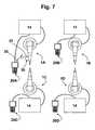
- FIG. 7Illustrated schematically in Figure 7 is a working cell that comprises a plurality of robots 1A, 1B, 1C, 1D, each equipped with a respective control unit 14.
- each unitis wire connected to a respective terminal or teach pendant 20A, 20B, 20C, 20D.
- the guide device 30 previously describedcan be used for programming any of the robots (the robot 1A, in the example illustrated), and then be transferred and interfaced in a simple and fast way to other robots of the plurality (1B, 1C, 1D), for the corresponding programming, and so forth for the other robots.
- the manual guide device 30can always remain paired to one and the same teach pendant 20, whereas the latter can be selectively coupled to each of the robots 1A, 1B, 1B, 1C of the cell. Hence, for such an application, it is sufficient to uncouple the device 30 from the robot 1A, then mount it on a different robot of the cell, for example, the robot 1B, and then carry out the calibration procedure described.
- Bluetooth technologyfor the purposes of implementation of the communication between the teach pendant 20 and the manual guide device 30, but it is clear that it is possible to implement for the purpose a radiofrequency communication network in compliance with other specifications, such as ZigBee, Wi-fi, Bluetooth, Z-Wave or some other wireless protocol of a standard or proprietary type.
Landscapes
- Engineering & Computer Science (AREA)
- Robotics (AREA)
- Mechanical Engineering (AREA)
- Physics & Mathematics (AREA)
- General Physics & Mathematics (AREA)
- Automation & Control Theory (AREA)
- Manipulator (AREA)
- Numerical Control (AREA)
Description
- The present invention relates to industrial robots and has been developed with particular reference being paid to devices used for carrying out the programming or "teaching" of industrial robots.
- The activity of programming of a robot basically consists in teaching the robot the path that a point of its movable structure must repeat automatically in the course of the normal working steps, to execute a certain operation. Said point is typically represented by the so-called"Tool Center Point" (TCP), which identifies in general the position of the active part of the tool mounted on the wrist of the robot, i.e., the part that executes the operation and that is defined by an operator in a convenient way according to the application. For example, in the case of an operation of arc welding, the TCP is located on the tip of the welding torch at the end of the welding wire; in sealing applications, the TCP is instead at a nozzle for outlet of the sealant, whilst, for applications that provides for the use of an electric spot-welding gun, the TCP corresponds to one of the two electrodes or an intermediate point between them.
- An industrial robot can then operate at least in an automatic mode and in a manual mode, usually selectable on the control unit of the robot. When the manual mode is selected, for example for the purposes of programming or teaching, the robot can be manoeuvred via commands imparted by a portable programming device, known as "teach pendant". Instead, when the automatic-operating mode is selected, the movement of the robot is governed only by the control unit.
- The majority of the programming time is dedicated to manual control of the robot, in order to identify the points deemed optimal of the paths of movement of the TCP, and store the corresponding co-ordinates thereof. For this purpose the teach pendant is used, which typically comprises a display and a series of pushbuttons, used for manoeuvring and programming the robot. The teach pendant is in general connected to the control unit by means of a long cable that enables the operator to move into the proximity of the working area of the robot, in order to be able to verify accurately the points and paths of the TCP. Also known are teach pendants connected to the control unit of the robot in wireless mode.
- For manual control of the variations of the posture of the robot, the operator uses specific pushbuttons of the teach pendant, known as jog pushbuttons or keys, which govern the movement of one or more axes of the robot. By acting on the jog buttons of the teach pendant, the TCP can be moved in a specific positive or negative direction in the range of a reference system selected by the operator from among a plurality of possible reference systems. In an anthropomorphic robot with six degrees of freedom, there are typically envisaged at least the "Joints", "Base", and "Tool" reference systems, where the "Joints" system is referenced to the joints of the robot (a vector in said system represents the angular positions of each of the joints), and the "Base" and "Tool" systems are cartesian reference systems, the former being referenced to the base of the robot and the latter to the tool mounted on the flange of the wrist of the robot.
- In order to follow the TCP closely and make a visual check on positioning thereof, the operator moves continuously around the robot: by so doing, the operator moves evidently also with respect to the origins of the aforesaid reference systems, and this complicates to a certain extent the activity of programming, also in view of the fact that the operator is each time called upon to select the reference system that he wishes to use.
- In order to render the activity of programming of the robot more intuitive, it has also been proposed to equip the robot with a manual guide device, mounted directly on the movable structure of the robot. Known devices of this type, generally based upon the use of a force/torque sensor connected to the control unit of the robot or else to the corresponding teach pendant via wired connection, are inconvenient to install, relatively cumbersome and costly, and their modalities of interfacing to the control system of the robot are frequently complex. These disadvantages also have the consequence of rendering the transferability of the guide device from one robot to another laborious, for example in the cases where a number of robots of one and the same working environment are to be programmed.
- A robot system having the features of the preamble of
claim 1 is known fromUS 6212443 A . - In the light of what is set forth above, the object of the present invention is basically to provide a robot system equipped with a manual guide device that is easy to install, simple to use, and inexpensive to produce, as well as being convenient and fast to interface to a portable programming terminal or teach pendant. The correlated object of the invention is to provide a manual guide device that can be transferred in a simple and fast way from one robot to another, for the purposes of the corresponding programming operations.
- The above and other purposes, which will emerge clearly hereinafter, are achieved according to the invention by a robot system and by a manual guide device for a robot having the characteristics indicated in the annexed claims. The claims form an integral part of the technical teaching provided herein in relation to the invention.
- Further purposes, characteristics and advantages of the present invention will emerge clearly from the ensuing description and the annexed drawings, which are provided purely by way of explanatory and non-limiting example and in which:
Figure 1 is a schematic illustration of a robot system according to the invention;Figure 2 is a schematic illustration of a portable programming terminal of the system ofFigure 1 ;Figure 3 illustrates with a simplified block diagram a possible control architecture of a robot of the system ofFigure 1 ;Figures 4 and 5 are schematic perspective illustrations of two possible practical implementations of a device for manual guiding of the robots of the system ofFigure 1 ;Figure 6 is a schematic view of an example of installation of the device ofFigure 5 ; andFigures 7 and8 are schematic representations in plan view of two machining cells, each implementing a robot system according to the invention.- Represented schematically in
Figure 1 is a robot system according to the invention, comprising arobot 1 having astructure 2 that is movable according to a number of degrees of freedom. In the example illustrated, the robot is an anthropomorphic robot having abase 3 and acolumn 4 mounted so that it can turn on thebase 3 about a first axis A1 directed vertically. Designated by 5 is an arm mounted oscillating on thecolumn 4 about a second axis A2 directed horizontally. Designated by 7 is a forearm mounted on thearm 5 about a third axis A3, which is also directed horizontally. Theforearm 7 moreover has the possibility of turning about its axis A4, which consequently constitutes a fourth axis of movement of therobot 1, and is equipped at its end with awrist 10, mounted for the movement according to two axes A5 and A6. Associated to the terminal flange of thewrist 10 is a tool or end effector, designated by 13, which in the example is represented by a welding torch with corresponding wire. As explained in the introductory part of the present description, the end of theend effector 13 constitutes a so-called "Tool Center Point" (TCP). - According to a technique in itself known, the movement of each of the
movable parts structure 2 is controlled by a respective electric motor with corresponding gear-reducing transmission. The movements of thestructure 2 and the operations of theend effector 13 are managed by a control unit, designated by 14 inFigure 1 , which is in a remote position with respect to thestructure 2 and is connected to the latter via a cable 15. - The system moreover comprises a portable programming terminal, or teach pendant, designated by 20, usable by an operator EU for manual programming of the
robot 1. The modalities of practical embodiment of the hardware relating to theunit 14 and to theterminal 20, equipped with respective microprocessor control system, are irrespective of the aims of the present description, apart from some aspects indicated hereinafter that regard the invention. - As previously explained, the operator EU can simulate a working step that the
robot 1 will then be called upon to perform automatically, varying the posture of the robot via purposely provided movement control means envisaged on theterminal 20, constituted by the so-called jog buttons; via other pushbuttons of theterminal 20 the operator EU can store the co-ordinates of the optimal path identified for the TCP. - Represented in
Figure 2 in a merely schematic form is an example of teachpendant 20, which comprises at least: - a
display 20a, through which the machine states, the program steps, possible alarms, and various parameters, such as the position of the axes of the manipulator, can be monitored; thedisplay 20a is used both during programming of the positions of the axes and of the movement program steps and as remote monitor of theunit 14; - a set of keys for governing the movement of the axes of the
robot 1, some of which designated by 20b; the keys of said set comprise in particular those for selection of the desired reference system of movement and the jog buttons; and - a set of programming and editing keys, some of which designated schematically by 20c, used for navigating within the programs displayed on the
display 20a, activating the various functions and entering data. - The
terminal 20 further comprises an emergency-stop device, designated by ES, which can be constituted by a mushroom-headed pushbutton, set in a fixed position on the front of the terminal. Pressure applied on said pushbutton enables immediate stopping/deactivation of the movement of the robot and/or of the entire operating cell in which the robot operates. The terminal is also equipped with an enabling device designated by ED, which is to be used in combination with the keys of theset 20b during the steps of learning or of manual control of movement of the robot. In practice, the enabling device ED is to be actuated or kept active by the operator, in order to enable therobot 1 to perform the desired movements during programming. In the non-limiting example ofFigure 2 , the device ED comprises two keys that extend along the side edges of theterminal 20, but in another possible embodiment the device ED can be located in the rear part of the terminal. - In the example represented, the control unit of the robot and the terminal are prearranged for communicating with one another in wireless mode, and for said purpose are equipped with means for exchange of signals over the air, comprising
respective transceiver modules 14a (Figure 1 ) and 24 (Figure 2 ). Said modules are sized so as to have a useful range of some metres, and hence fall within the range of theterminal 20 with respect to theunit 14. Transmission over the air of the signals can occur according to any known technique. In a preferred embodiment, the wireless communication between theunit 14 and theTerminal 1 20 occurs in radiofrequency, using the transmission system defined by the IEEE 802. 11a standard (to which the reader is referred integrally for further details), known as Wi-fi. - The wireless connection between the
terminal 20 and theunit 14 basically enables exchange of the following three types of information : - a) operating data, such as information regarding the dimensions of the axes, the jog commands, and in general all the selections that can be made via the
terminal 20, as well as downloading of software from the terminal itself to theunit 14; also theunit 14 can send data to theterminal 20, such as information necessary for updating of the display windows on thedisplay 20a, warning codes (alarms, machine states, etc.), uploading of programs, etc.; - b) state of the emergency-stop device ES; and
- c) state of the enabling device ED.
- The terminal 20 further comprises an
electrical connector 23, forming part of an arrangement for recharging an internal battery of the terminal, and at least onecommunication port 25. In a preferred embodiment, theport 25 is a USB port. - The control logic of the system envisages that the jog buttons command each time functions of translation and functions of rotation of axes of the
robot 1 with reference to the various possible reference systems, such as those referred to as Joints, Base and Tool, which the operator EU must each time choose and select previously. Said circumstance, as previously explained, can render the activity of programming via the terminal 20 far from intuitive. - For this reason, directly associated to the
movable structure 2 of therobot 1 is a manual guide device, to which the invention refers in a specific way and which is designated as a whole by 30 inFigure 1 . Theguide device 30 is provided with additional control means, which can be used as an alternative to the jog keys of the terminal or teachpendant 20 for governing the movement of the robot during programming. - Represented via a block diagram in
Figure 3 is the general architecture for control of the robot, including theunit 14, the terminal 20, and theguide device 30. - The
guide device 30 has a microprocessor electronic control system, of a programmable type and provided with permanent rewritable memory means, designated as a whole by 31. Preferentially, the circuit is of a miniaturized type, and can be implemented, for example, using a board of a "FOX Board" type, produced by the company ACME Systems Sr1, Rome, Italy, to the technical documentation of which the reader is referred for further details. Designated by 32 are the movement control means of the robot belonging to thedevice 30. In the preferred embodiment of the invention, these means are constituted by a joystick with a number of degrees of freedom, particularly an optical-sensor joystick with six degrees of freedom. Joysticks of the type indicated are commercially available, at contained costs, and are extremely precise. A device usable for this purpose is, for example, the one referred to asSpace Navigator™, marketed by the company 3DConnexion GmbH, Seefeld, Germany, to the technical documentation of which the reader is referred for further detail. The device moreover comprises some keys, amongst which, for example, a key 33 for turning on/turning off the device and astorage key 34, usable by the operator EU for storing the co-ordinates of the points of the path identified for the TCP. - The
device 30 further comprises anautonomous supply source 35, such as a battery, which is preferentially of a rechargeable type. For this purpose, thedevice 30 is also conveniently provided with aconnector 36 for connection to a recharging device of a known type, not represented. - According to the main characteristic of the invention, the
manual guide device 30 is provided with wireless communication means, in order to set up a wireless communication channel for communication with theportable terminal 20. The communication means comprise for said purpose a first transceiver module on themanual guide device 30 and a second transceiver module on theportable terminal 20. - The first wireless transceiver module is designated by 37 in
Figure 2 and is connected to thecontrol system 31. In a preferred embodiment of the invention, themodule 37 is prearranged for operating according to the Bluetooth standard and can be implemented by any transceiver suited for the purpose. The use of Bluetooth technology proves particularly advantageous both as regards the easy traceability and the contained cost of the transceivers and because the typical mode of operation envisaged by the Bluetooth standard enables containment of the levels of consumption of electrical energy by thedevice 30. - In a possible practical embodiment, the
module 37 can be of the "key" type in order to enable connection to thecontrol system 31 exploiting a communication port of the latter, particularly a USB port; in an example, themodule 37 will have a USB plug, and the aforesaid port will have a USB socket. In such a case, thecontrol system 31 of thedevice 30 is preferentially configured for effecting installation of the peripheral represented by themodule 37 via theplug-and-play technique. It should on the other hand be borne in mind that themodule 37, irrespective of its practical implementation, does not necessarily have to be associated to thedevice 30 in a removable way. - Also the terminal 20 is provided with a corresponding microprocessor programmable electronic control system, designated by 21, equipped with corresponding memory means, to which the various keys of the device (designated as a whole by K in
Figure 3 ) and thedisplay 20a are interfaced in a known way, the latter possibly being implemented with touch-screen technology. - As already mentioned, the terminal 20 has a corresponding
autonomous supply source 22, such as a battery, preferentially of a rechargeable type and with aconnector 23 for connection to a suitable recharging arrangement (not represented). - Associated to the
control system 21 are first transceiver means for wireless signals, designated by 24, for communicating with similar transceiver means 14a of thecontrol unit 14 of therobot 1. As already explained, these transceiver means operate, in a possible embodiment, according to the Wi-fi communication standard. - The
control system 21 of the terminal 20 is moreover provided with at least onecommunication port 25 accessible from outside the teach pendant, preferably of a USB type. It should be noted that practically all teach pendants commonly used in combination with industrial robots are provided with at least one accessible communication port. - Connectable in a removable way to said
port 25 is the second transceiver module, designated by 26, forming part of the communication means provided to enable dialogue in wireless mode between thedevice 30 and the terminal 20. - Consequently, in the example considered, the
module 26, which can be implemented via any transceiver suited to the purpose, operates according to the Bluetooth standard. In the preferred embodiment of the invention, themodule 26 is of the "key" type in order to enable connection to thecontrol system 21, exploiting thecommunication port 25. As has been said, theport 25 is preferably of a USB type, in which case themodule 26 will preferentially have a USB plug and theport 25 will have a USB socket. Preferably, thecontrol system 21 of the terminal 20 is configured to enable installation of the peripheral represented by themodule 26 via theplug-and-play technique. - Illustrated in
Figure 4 is a possible practical embodiment of thedevice 30, which comprises a casing of a prismatic shape, housed within which is the corresponding control system, and mounted on which is thejoystick 32 with six degrees of freedom, with thekeys connector 36, and thetransceiver module 37. As has been said, the control circuit of thedevice 30 is of a miniaturized type so that the dimensions of its casing are small, indicatively less than 10 cm in the three dimensions. - The
device 30 is provided with means for its coupling, at the axis A6, to one of themovable structure 2 and theend effector 13 of therobot 1, said means being preferably configured to enable a fast coupling or assembly. In the embodiment exemplified inFigure 5 anassembly base 40 is purposely provided, equipped with straps or clamps 41 for fast fixing to the structure of the robot or directly to the tool (of course, instead of clamps, other means of assembly can be used, such as for example adjustable collars). - Exemplified, for instance, in
Figure 6 is the coupling of theguide device 30 to one of theelectrodes 51 of awelding gun 50 mounted on thewrist 10 of the robot. In the case ofFigure 1 , instead, thedevice 30 is fixed to the support of thetorch 13 via screws, for example exploiting the presence of purposely providedholes 42 made in the base 40 or in a base of the casing of thedevice 30. - In the example of
Figure 5 , the casing of thedevice 30 has arespective base 38 that defines one ormore engagement seats 39 designed to receiverespective portions 43 of theassembly base 40, with a substantially slide-type coupling. Secure fixing between thebases - The
guide device 30 can be used in the case where it is intended to facilitate programming of the robot, via means alternative to the jog keys of the terminal 20, simplifying also movement of the robot in its range of application. Preferentially, the movement of therobot 1 by means of thedevice 30 occurs in a cartesian reference system, i.e., in the "Tool" reference system, in a way independent of the reference system possibly selected for the terminal 20. In other words, the movement of the TCP determined by actuation of thejoystick 32 is not affected by the current setting of the jog keys, so that it is sufficient for the operator EU to actuate thejoystick 32 in the desired direction in order to produce a corresponding movement of therobot 1. It should in any case be noted that the joystick is a control means additional to the jog keys: consequently, the movement of the TCP to reach the desired point can always be governed by the operator EU using the teach pendant, after prior selection of the desired reference system. - Using the joystick device it is possible to move the TCP of the
robot 1 in all the directions of the "Tool" reference system (and following all the rotations). In a preferred embodiment of the invention, it is possible, using the teach pendant, to block some movements (blocking the degrees of freedom), with the possibility of moving the robot along a plane or a straight line, possibly also in a reference system different from the "Tool" reference system, previously selectable according to an appropriate procedure on the terminal 20. - As has been said, the joystick has preferentially six degrees of freedom. For example, by exerting a pressure or else a pulling action on the knob of the
joystick 32, an advance or a recession of the TPC is obtained; by pressing the knob to the right or to the left, a displacement to the right and to the left, respectively, of the TCP is obtained. Likewise, by pushing the knob down or up, the corresponding movements of the TCP are obtained. The knob can likewise be turned in a clockwise direction and in a counterclockwise direction to obtain movements of rotation of the TCP, or else be inclined to obtain inclinations of the TCP in the desired direction. - As previously explained, in a possible embodiment of the invention the
device 30 communicates with the terminal 20 through a Bluetooth system, which guarantees low consumption levels, using the UDP (User Datagram Protocol). The communication protocol is preferentially a dedicated protocol, based upon encapsulated messages as body of a UDP packet. - The practical modes of implementation of the communication between the
device 30 and the terminal 20, as well as between the latter and thecontrol unit 14 of the robot, can be of any type. - In general terms, the terminal 20 operates alternatively as client and as server in regard to the
guide device 30. The terminal 20 behaves as UDP client in regard to thedevice 30 for the messages of initial configuration and messages of movement, requesting at each instant - for example, every 10 ms - the position of the knob of thejoystick 32, with the corresponding control system that responds in a synchronous way. With a touch or release of the knob of the joystick by the user, detected by thecontrol system 31 of thedevice 30, this sends a message of activation to the terminal 20, which in this case behaves as UDP server for the messages of action, i.e., control of the displacement of the robot. - The modalities of communication between the terminal 20 and the
control unit 14 of the robot is substantially analogous to the one described above, but the terminal 20 behaves always as a UDP client for the messages of configuration and movement, whereas thecontrol unit 14 is configured for handling a task that is launched at start-up of the system with the UDP server in listening mode. The aforesaid task in theunit 14 is provided for handling the messages of interchange between the task of communication present on the terminal 20 (which behaves as client) and the task on the unit 14 (server). The task on theunit 14 is configured for establishing whether, in the communication when waiting for a message there occurs a timeout or an error in reception, and makes a series of attempts in such a way as to be able to guarantee a percentage of error in reception such as not to have an adverse effect on the performance of the communication. Upon receipt of a packet of an action type (movement of the robot), the server process responds to the terminal 20 with a message containing the current position of the TCP and the state of the enabling device ED of the terminal. - In the case where via the terminal 20 deactivation of the
guide device 30 is requested, the corresponding module is deactiveted within the interpolator of thecontrol 14; otherwise, the system activates thedevice 30. During the step in which in the system device 30 -terminal 20 carries out polling to supply the current position to thecontrol 14, the server on thecontrol 14 receives the data regarding the position reference of thedevice 30 and responds to the task client on the terminal 20 with the current position of the TCP, from which the reference systems commonly active on the system have previously been removed. Finally, the task client on the terminal 20 requests at a regular rate from the task server the reference systems active on the system, which are, however, used in combination with thedevice 30 only for management of possible advanced movements, as has been said previously (blocking of the degrees of freedom). - The part of communication between the
teach pendant 20 and thecontrol unit 14 can be basically divided into two parts. The part of the communication between the user interface (display) of the terminal 20 and thedevice 30, and the part for management at a lower level of the communication and handshaking between the terminal 20 and thedevice 30, and between the terminal 20 and thecontrol unit 14. The first part concerns the exchange of information that occurs between the user interface of the teach pendant (hence, for example, information regarding the state of the system, the configuration, and set-up of the device), is established upon start-up of the system and updating of the data between the teach pendant and the guide device, and is performed whenever the graphic interface on the teach pendant requests an updating of the data to be displayed, or when there are entered from the user interface configuration values that are to be passed to theguide device 30. - The second part of the communication between the teach pendant and the
device 30 is, instead, as has already been said, at a lower level and deals prevalently with the initialization part of the communication (start-up of the Bluetooth protocol and adaptation to the TCP/IP protocol with the Bluetooth Network Encapsulation Protocol - BNEP) and the part of renewal of the connection between thedevice 30 and the terminal 20 and between the terminal 20 and thecontrol unit 14. All the messages that regard the movement and updating of the reference systems are managed by this task on the terminal 20. - Thanks to its own microprocessor control system, the
device 30 is configurable, in so far as, in the communication protocol, different messages can be integrated for entering the parameters of the guide device. Preferentially, there is envisaged the possibility of configuring the position of thedevice 30 with respect to the axis A6 of the robot, the maximum speeds and the accelerations that may be allowed for translations and rotations, the number and the gear-reducing ratio, the limitation of the degrees of freedom, and the configuration of the reference systems. - In the preferred embodiment, integrated in the control logic of the system is a calibration procedure controllable by means of the terminal 20, which enables configuration of the
guide device 30 in any point of the "Tool" system of co-ordinates starting from the axis A6 of the robot. The procedure is preferentially guided via the display of the teach pendant, through which there is first requested positioning of therobot 1, by a command issued by thedevice 30, in a position such that a side face of the casing of the device itself is substantially parallel to thebase 3 of the robot or to the ground; in this a way, the calibration procedure can occur more easily. Next, the system requests the user, once again via the display of the teach pendant, to act on thejoystick 32 in such a way as to cause displacements in the directions X, Y, Z of the "Base" reference system in such a way as to be able to calculate the conversion of co-ordinates between the "Tool" reference system of thedevice 30 and the "Base" reference system of the robot. If the procedure of acquisition of the directions has been performed correctly, the system sends back on the display a message to indicate that calibration has been performed and in this way it will be possible to use thedevice 30 in the position just calibrated. Of course, it is possible to execute the calibration procedure for "n" possible points of installation of thedevice 30 on the robot, and each configuration will preferentially be saved on theunit 14 and not on thedevice 30, which can be used also on robots different from the one currently being programmed. - To guarantee coupling of the terminal 20 with the
manual guide device 30, it is necessary for the Bluetooth transceiver modules to be uniquely identified. The unique coupling between thedevice 30 and the terminal 20, purposely configured, is guaranteed through a pairing procedure that envisages scanning by the terminal, via the correspondingmodule 26, of the Bluetooth network so as to identify the Bluetooth devices present. Thedevice 30 responds to the scanning, via the correspondingtransceiver module 37, with an identifier or information of identity that coincides with the identifier or information of identity of themodule 26 paired with the terminal 20. Preferentially, said identifier is represented by the MAC address of themodule 26 of the terminal 20. The terminal is able to query the correspondingtransceiver module 37 to identify the aforesaid identifier and to enable pairing or otherwise. The uniqueness of the identifier evidently guarantees the uniqueness of the pairing. - In normal use, the
device 30 is mounted on therobot 1, in a position corresponding to the axis A6, for example directly on theend effector 13. Next, the logic pairing and calibration procedures described above are performed. Next, therobot 1 can be manoeuvred by the operator EU by directly acting on thejoystick 32, as described previously. As explained, the possibility of manoeuvring therobot 1 using thedevice 30 depends always and in any case upon the state of activation of the enabling device ED provided on the terminal 20. - From the foregoing description, the characteristics of the present invention emerge clearly. The manual guide device proposed is simple and economically advantageous to produce and ensures precise and reliable operation. The fact that the device is provided with means for establishing a wireless communication with a teach pendant renders transportability or transferability of the device between different robots to be programmed very convenient and fast. As has been said, the fact that practically all the teach pendants for industrial robots are provided with at least one communication port renders implementation of the invention very easy, it being sufficient to combine with such a port a module of the wireless communication system. Of course, the absence of a cable between the teach pendant and the manual guide device has also the practical advantage of facilitating the displacements of the operator in the proximity of the TCP.
- The contained dimensions of the device and the provision of coupling means of a substantially fast-coupling type further facilitate the transportability of the device itself and, in addition to facilitating its installation, enabling positioning of the device in various possible positions on the robot.
- The advantages in terms of transportability of the
device 30 are highlighted inFigures 7 and8 . - Illustrated schematically in
Figure 7 is a working cell that comprises a plurality ofrobots respective control unit 14. In the example ofFigure 7 , each unit is wire connected to a respective terminal or teachpendant guide device 30 previously described can be used for programming any of the robots (therobot 1A, in the example illustrated), and then be transferred and interfaced in a simple and fast way to other robots of the plurality (1B, 1C, 1D), for the corresponding programming, and so forth for the other robots. For this purpose, it is in fact sufficient to uncouple thedevice 30 from therobot 1A, and then mount it on a different robot of the cell, for example, therobot 1B, as well as transfer the transceiver module from theteach pendant 20A to theteach pendant 20B in order to carry out then the procedures of pairing and calibration described. - Even more convenient is the case where the working cell is provided with a single teach pendant of a wireless type, of the sort that can be coupled selectively to any of the
control units 14, as schematically illustrated inFigure 8 . A technique that can be used for this purpose is the one described in the document No.EP-B-1 716 983 (with particular reference to the connection defined as "Main" in said document). - In this application, the
manual guide device 30 can always remain paired to one and thesame teach pendant 20, whereas the latter can be selectively coupled to each of therobots device 30 from therobot 1A, then mount it on a different robot of the cell, for example, therobot 1B, and then carry out the calibration procedure described. - Previously, reference has been made to Bluetooth technology for the purposes of implementation of the communication between the
teach pendant 20 and themanual guide device 30, but it is clear that it is possible to implement for the purpose a radiofrequency communication network in compliance with other specifications, such as ZigBee, Wi-fi, Bluetooth, Z-Wave or some other wireless protocol of a standard or proprietary type.
Claims (14)
- A robot system that comprises:- at least one robot (1; 1A-1D) having a control unit (14) and a movable structure (2) to which an end effector (13; 50) is associated;- at least one portable programming terminal (20; 20A-20D) in data communication with the control unit (14), including a manually actuatable enabling device (ED) for enabling manual control of displacements of the movable structure (2) of the robot (1); and- a manual guide device (30), provided with means (38-41) for coupling thereof to at least one of the movable structure (2) and the end effector (13; 50) of the robot (1; 1A-1D),
characterized in that- the manual guide device (30) has wireless communication means (26, 37) to set up a wireless communication channel for communication with the portable terminal (20; 20A-20D),- the wireless communication means comprises a first wireless transceiver module (37) on the manual guide device (30) and a second wireless transceiver module (26) on the portable terminal (20; 20A-20D), and- at least the second wireless transceiver module (26) is prearranged for being physically connected in a separable way to the portable terminal (20; 20A). - The system according to Claim 1, comprising a plurality of robots (1A-1D), wherein the wireless communication means (26, 37) are prearranged for the selective connection in wireless mode of the manual guide device (30) to the portable terminal (20A) that is in data communication with the control unit (14) of any (1A) of the robots of said plurality (1A-1D) that is to be programmed.
- The system according to Claim 1, wherein the wireless communication means (26, 37) are prearranged to set up a unique connection between the manual guide device (30) and the portable terminal (20; 20A).
- The system according to Claim 3, wherein- one of the first and second wireless transceiver modules (26, 37) contains information of identity of the other of the first and second wireless transceiver modules, particularly corresponding to a MAC address; and- the manual guide device (30) and the portable terminal (20; 20A) are configured in such a way that, in the course of a pairing procedure necessary for enabling a session of use of the manual guide device (30), said information of identity is communicated from one wireless transceiver module to the other wireless transceiver module.
- The system according to at least one of the preceding claims, wherein said means for coupling the manual guide device (30) to at least one of the movable structure (2) and the end effector (13; 50) comprise fast-coupling means (38-41).
- The system according to Claim 2, wherein the portable terminal (20) comprises further wireless communication means (24), the control units (14) of the robots of said plurality (1A-1D) are provided with respective wireless communication means (14A), and the portable terminal (20) is selectively connectable in wireless mode to the control unit (14) of any robot (1A) of said plurality (1A-1D) that is to be programmed.
- The system according to at least one of the preceding claims, wherein the manual guide device (30) comprises a joystick with a number of degrees of freedom (32), particularly an optical-sensor joystick with six degrees of freedom.
- The system according to at least one of the preceding claims, wherein the portable terminal (20) comprises a microprocessor electronic control system (21) having at least one communication port (25) to which the second wireless transceiver module (26) is connectable in a separable way.
- The system according to claim 8, wherein said communication port is a USB port (25).
- The system according to Claim 1, wherein the manual guide device (30) is provided with an autonomous supply source (35), particularly a battery of a rechargeable type.
- The system according to at least one of the preceding claims, wherein at least one of the portable terminal (20) and the control unit (14) with which the portable terminal (20) is in data communication are configured in such a way that the movement allowed for the movable structure (2) of the robot (1; 1A), which can be controlled via the manual guide device (30), can be selectively limited for one or more degrees of freedom.
- The system according to at least one of the preceding claims, wherein the manual guide device (30), the portable terminal (20) and the control unit (14) with which the portable terminal (20) is in data communication are configured for the purposes of execution of a procedure of calibration of the manual guide device (30).
- The system according to at least one of the preceding claims, wherein the manual guide device (30) comprises a plurality of control means (33, 34), particularly at least one ON/OFF key (33) and a key for storage of position co-ordinates (34).
- The system according to claim 2, comprising a plurality of said portable terminals (20A-20D) and wherein each robot of said plurality of robots (1A-1D) comprises a respective control unit (14) to which a respective one portable terminal of said plurality of portable terminals (20A-20D) is wire connected.
Priority Applications (4)
| Application Number | Priority Date | Filing Date | Title |
|---|---|---|---|
| EP08425778AEP2194434B1 (en) | 2008-12-05 | 2008-12-05 | Robot system |
| US12/616,328US8412379B2 (en) | 2008-12-05 | 2009-11-11 | Robot system |
| JP2009275462AJP2010149273A (en) | 2008-12-05 | 2009-12-03 | Robot system |
| JP2013006888UJP3188939U (en) | 2008-12-05 | 2013-12-04 | Robot system |
Applications Claiming Priority (1)
| Application Number | Priority Date | Filing Date | Title |
|---|---|---|---|
| EP08425778AEP2194434B1 (en) | 2008-12-05 | 2008-12-05 | Robot system |
Publications (2)
| Publication Number | Publication Date |
|---|---|
| EP2194434A1 EP2194434A1 (en) | 2010-06-09 |
| EP2194434B1true EP2194434B1 (en) | 2012-05-30 |
Family
ID=40560308
Family Applications (1)
| Application Number | Title | Priority Date | Filing Date |
|---|---|---|---|
| EP08425778AActiveEP2194434B1 (en) | 2008-12-05 | 2008-12-05 | Robot system |
Country Status (3)
| Country | Link |
|---|---|
| US (1) | US8412379B2 (en) |
| EP (1) | EP2194434B1 (en) |
| JP (2) | JP2010149273A (en) |
Cited By (6)
| Publication number | Priority date | Publication date | Assignee | Title |
|---|---|---|---|---|
| DE102014226933B3 (en)* | 2014-12-23 | 2016-03-24 | Kuka Roboter Gmbh | Device and method for recording positions |
| CN108202329A (en)* | 2017-12-31 | 2018-06-26 | 芜湖哈特机器人产业技术研究院有限公司 | A kind of method that robot demonstrator is communicated with controller data with parsing |
| DE102018114644B3 (en) | 2018-06-19 | 2019-09-19 | Deutsches Zentrum für Luft- und Raumfahrt e.V. | Manual learning process on a robot manipulator with force / torque specification |
| US11858130B2 (en) | 2018-12-07 | 2024-01-02 | Fanuc Corporation | Controller of robot for performing manual operation by operation device |
| WO2024105171A1 (en) | 2022-11-17 | 2024-05-23 | Deutsches Zentrum für Luft- und Raumfahrt e.V. | Robot arm, ultrasound robot, and method for controlling a robot arm |
| DE102019131775B4 (en) | 2018-11-29 | 2025-03-06 | Fanuc Corporation | robot control device |
Families Citing this family (94)
| Publication number | Priority date | Publication date | Assignee | Title |
|---|---|---|---|---|
| WO2009146359A1 (en) | 2008-05-28 | 2009-12-03 | Illinois Tool Works Inc. | Welding training system |
| DE102010063222B4 (en)* | 2010-12-16 | 2019-02-14 | Robert Bosch Gmbh | Device and method for programming a handling device and handling device |
| US20170028557A1 (en)* | 2015-07-28 | 2017-02-02 | Comprehensive Engineering Solutions, Inc. | Robotic navigation system and method |
| US9101994B2 (en) | 2011-08-10 | 2015-08-11 | Illinois Tool Works Inc. | System and device for welding training |
| WO2013029658A1 (en)* | 2011-08-30 | 2013-03-07 | Abb Technology Ag | Enabling device transferring robot control signals |
| EP2570878A1 (en)* | 2011-09-17 | 2013-03-20 | Mikron Agie Charmilles AG | CNC machine without operating console |
| US9770828B2 (en)* | 2011-09-28 | 2017-09-26 | The Johns Hopkins University | Teleoperative-cooperative robotic system |
| JP2013099815A (en)* | 2011-11-08 | 2013-05-23 | Fanuc Ltd | Robot programming device |
| JP6052576B2 (en)* | 2012-05-30 | 2016-12-27 | 日本電気株式会社 | Information processing system, information processing method, information processing apparatus, portable terminal, and control method and control program thereof |
| US9583014B2 (en) | 2012-11-09 | 2017-02-28 | Illinois Tool Works Inc. | System and device for welding training |
| US9672757B2 (en) | 2013-03-15 | 2017-06-06 | Illinois Tool Works Inc. | Multi-mode software and method for a welding training system |
| US9583023B2 (en) | 2013-03-15 | 2017-02-28 | Illinois Tool Works Inc. | Welding torch for a welding training system |
| US9666100B2 (en) | 2013-03-15 | 2017-05-30 | Illinois Tool Works Inc. | Calibration devices for a welding training system |
| US9713852B2 (en) | 2013-03-15 | 2017-07-25 | Illinois Tool Works Inc. | Welding training systems and devices |
| US9728103B2 (en) | 2013-03-15 | 2017-08-08 | Illinois Tool Works Inc. | Data storage and analysis for a welding training system |
| US10056010B2 (en) | 2013-12-03 | 2018-08-21 | Illinois Tool Works Inc. | Systems and methods for a weld training system |
| US10105782B2 (en) | 2014-01-07 | 2018-10-23 | Illinois Tool Works Inc. | Feedback from a welding torch of a welding system |
| US9751149B2 (en) | 2014-01-07 | 2017-09-05 | Illinois Tool Works Inc. | Welding stand for a welding system |
| US9757819B2 (en) | 2014-01-07 | 2017-09-12 | Illinois Tool Works Inc. | Calibration tool and method for a welding system |
| US9724788B2 (en) | 2014-01-07 | 2017-08-08 | Illinois Tool Works Inc. | Electrical assemblies for a welding system |
| US9589481B2 (en) | 2014-01-07 | 2017-03-07 | Illinois Tool Works Inc. | Welding software for detection and control of devices and for analysis of data |
| US10170019B2 (en) | 2014-01-07 | 2019-01-01 | Illinois Tool Works Inc. | Feedback from a welding torch of a welding system |
| EP3112079A4 (en)* | 2014-02-24 | 2017-03-15 | Howon Co. Ltd. | Hybrid welder |
| DE102014004919B4 (en) | 2014-04-07 | 2022-05-12 | Abb Schweiz Ag | Method and means for manipulating an object |
| US10665128B2 (en) | 2014-06-27 | 2020-05-26 | Illinois Tool Works Inc. | System and method of monitoring welding information |
| US10307853B2 (en) | 2014-06-27 | 2019-06-04 | Illinois Tool Works Inc. | System and method for managing welding data |
| US9937578B2 (en) | 2014-06-27 | 2018-04-10 | Illinois Tool Works Inc. | System and method for remote welding training |
| US9862049B2 (en) | 2014-06-27 | 2018-01-09 | Illinois Tool Works Inc. | System and method of welding system operator identification |
| US11014183B2 (en) | 2014-08-07 | 2021-05-25 | Illinois Tool Works Inc. | System and method of marking a welding workpiece |
| US9724787B2 (en) | 2014-08-07 | 2017-08-08 | Illinois Tool Works Inc. | System and method of monitoring a welding environment |
| US9875665B2 (en) | 2014-08-18 | 2018-01-23 | Illinois Tool Works Inc. | Weld training system and method |
| US9815206B2 (en)* | 2014-09-25 | 2017-11-14 | The Johns Hopkins University | Surgical system user interface using cooperatively-controlled robot |
| US10239147B2 (en) | 2014-10-16 | 2019-03-26 | Illinois Tool Works Inc. | Sensor-based power controls for a welding system |
| US11247289B2 (en) | 2014-10-16 | 2022-02-15 | Illinois Tool Works Inc. | Remote power supply parameter adjustment |
| US9597807B2 (en)* | 2014-10-24 | 2017-03-21 | Hiwin Technologies Corp. | Robot teaching device |
| US10373304B2 (en) | 2014-11-05 | 2019-08-06 | Illinois Tool Works Inc. | System and method of arranging welding device markers |
| US10204406B2 (en) | 2014-11-05 | 2019-02-12 | Illinois Tool Works Inc. | System and method of controlling welding system camera exposure and marker illumination |
| US10490098B2 (en) | 2014-11-05 | 2019-11-26 | Illinois Tool Works Inc. | System and method of recording multi-run data |
| US10402959B2 (en) | 2014-11-05 | 2019-09-03 | Illinois Tool Works Inc. | System and method of active torch marker control |
| US10210773B2 (en) | 2014-11-05 | 2019-02-19 | Illinois Tool Works Inc. | System and method for welding torch display |
| US10417934B2 (en) | 2014-11-05 | 2019-09-17 | Illinois Tool Works Inc. | System and method of reviewing weld data |
| ES2648295T3 (en) | 2014-11-07 | 2017-12-29 | Comau S.P.A. | Industrial robot and control procedure of an industrial robot |
| US9804593B1 (en)* | 2014-12-12 | 2017-10-31 | X Development Llc | Methods and systems for teaching positions to components of devices |
| DE102015200428B3 (en)* | 2015-01-14 | 2016-03-17 | Kuka Roboter Gmbh | Method for aligning a multi-axis manipulator with an input device |
| US10427239B2 (en) | 2015-04-02 | 2019-10-01 | Illinois Tool Works Inc. | Systems and methods for tracking weld training arc parameters |
| WO2016161444A1 (en)* | 2015-04-03 | 2016-10-06 | Think Surgical, Inc. | Robotic system with intuitive motion control |
| CN105033996B (en)* | 2015-05-22 | 2017-04-12 | 苏州法鲁克自动化设备有限公司 | Control system based on hand-push teaching type five-shaft horizontal joint robot |
| US9925662B1 (en)* | 2015-06-28 | 2018-03-27 | X Development Llc | Generating a trained robot path based on physical manipulation of the robot and based on training user interface input(s) associated with the physical manipulation |
| US20170028549A1 (en)* | 2015-07-28 | 2017-02-02 | Comprehensive Engineering Solutions, Inc. | Robotic navigation system and method |
| US10593230B2 (en) | 2015-08-12 | 2020-03-17 | Illinois Tool Works Inc. | Stick welding electrode holder systems and methods |
| US10657839B2 (en) | 2015-08-12 | 2020-05-19 | Illinois Tool Works Inc. | Stick welding electrode holders with real-time feedback features |
| US10438505B2 (en) | 2015-08-12 | 2019-10-08 | Illinois Tool Works | Welding training system interface |
| US10373517B2 (en) | 2015-08-12 | 2019-08-06 | Illinois Tool Works Inc. | Simulation stick welding electrode holder systems and methods |
| ITUB20169976A1 (en) | 2016-01-14 | 2017-07-14 | Comau Spa | System for robot-assisted control of a transrectal probe, for example for use in performing a prostatic ultrasound |
| DE102016016051B4 (en)* | 2016-01-15 | 2024-02-29 | Kuka Deutschland Gmbh | Robot assembly with handheld |
| DE102016000362B4 (en)* | 2016-01-15 | 2024-10-31 | Kuka Deutschland Gmbh | robot arrangement with handheld |
| DE102016202881B4 (en)* | 2016-02-24 | 2018-01-18 | Kuka Roboter Gmbh | Operating device for manipulator |
| AT518481B1 (en)* | 2016-03-07 | 2018-09-15 | Keba Ag | System and method for the spatial movement of an object |
| DE102016204137A1 (en)* | 2016-03-14 | 2017-09-14 | Kuka Roboter Gmbh | Programmable manipulator system with a function switch device |
| DE202016002733U1 (en)* | 2016-04-22 | 2017-07-26 | Kuka Roboter Gmbh | End effector means |
| JP6338617B2 (en)* | 2016-05-31 | 2018-06-06 | 株式会社アスコ | Teaching device |
| DE102016222675C5 (en) | 2016-11-17 | 2022-03-31 | Kuka Deutschland Gmbh | Robotic handheld device, associated docking device, robot and method |
| US10207404B2 (en) | 2017-02-09 | 2019-02-19 | X Development Llc | Generating a robot control policy from demonstrations collected via kinesthetic teaching of a robot |
| US10960543B2 (en)* | 2017-05-30 | 2021-03-30 | Sisu Devices, LLC | Robotic point capture and motion control |
| US11565412B2 (en)* | 2017-09-15 | 2023-01-31 | Google Llc | Generating a robot control policy from demonstrations collected via kinesthetic teaching of a robot |
| JP1606242S (en)* | 2017-11-22 | 2018-06-11 | ||
| JP6730247B2 (en) | 2017-11-28 | 2020-07-29 | ファナック株式会社 | Robot operating device |
| JP6737765B2 (en)* | 2017-11-28 | 2020-08-12 | ファナック株式会社 | Robot teaching system, controller and hand guide unit |
| US12186879B2 (en)* | 2018-01-18 | 2025-01-07 | Ingersoll-Rand Industrial U.S., Inc. | Add-on user interface module for precision power tools |
| IT201800005091A1 (en) | 2018-05-04 | 2019-11-04 | "Procedure for monitoring the operating status of a processing station, its monitoring system and IT product" | |
| US11839979B2 (en)* | 2018-06-15 | 2023-12-12 | Universal Robots A/S | Dual mode free-drive of robot arm |
| JP1646783S (en)* | 2019-02-13 | 2019-12-02 | ||
| JP1646782S (en)* | 2019-02-13 | 2019-12-02 | ||
| JP1646794S (en)* | 2019-03-14 | 2019-12-02 | ||
| JP1646798S (en)* | 2019-03-14 | 2019-12-02 | ||
| JP1646795S (en)* | 2019-03-14 | 2019-12-02 | ||
| JP1646793S (en)* | 2019-03-14 | 2019-12-02 | ||
| JP1646799S (en)* | 2019-03-14 | 2019-12-02 | ||
| JP1646797S (en)* | 2019-03-14 | 2019-12-02 | ||
| JP1646796S (en)* | 2019-03-14 | 2019-12-02 | ||
| JP1646800S (en)* | 2019-03-14 | 2019-12-02 | ||
| USD892885S1 (en)* | 2019-05-03 | 2020-08-11 | Carbon Robotics, Inc. | Robotic arm segment |
| JP7294880B2 (en) | 2019-05-20 | 2023-06-20 | ファナック株式会社 | ROBOT CONTROL DEVICE, ROBOT SYSTEM, AND ROBOT CONTROL METHOD |
| IT201900008769A1 (en) | 2019-06-17 | 2020-12-17 | Maurizio Corridori | Intuitive interface for the control and programming of an industrial robot manipulator |
| US11154985B1 (en)* | 2019-07-02 | 2021-10-26 | X Development Llc | Null space jog control for robotic arm |
| US11776423B2 (en) | 2019-07-22 | 2023-10-03 | Illinois Tool Works Inc. | Connection boxes for gas tungsten arc welding training systems |
| US11288978B2 (en) | 2019-07-22 | 2022-03-29 | Illinois Tool Works Inc. | Gas tungsten arc welding training systems |
| DK180508B1 (en) | 2019-10-22 | 2021-06-03 | Universal Robots As | Maintaining free-drive mode of robot arm for period of time |
| CN114585483A (en) | 2019-10-22 | 2022-06-03 | 优傲机器人公司 | Safely activate the free drive mode of the robot arm |
| EP4049104A1 (en) | 2019-10-22 | 2022-08-31 | Universal Robots A/S | Robot arm with adaptive three-dimensional boundary in free-drive |
| KR102471860B1 (en)* | 2021-01-22 | 2022-11-30 | 주식회사 푸른기술 | Direct teaching apparatus attached to collaborative robot |
| EP4615659A1 (en)* | 2022-11-07 | 2025-09-17 | Illinois Tool Works Inc. | Systems and methods to configure a robotic welding system |
| WO2024113286A1 (en)* | 2022-11-30 | 2024-06-06 | Abb Schweiz Ag | Method and system for programming an industrial robot |
| JP7529920B1 (en)* | 2023-04-24 | 2024-08-06 | ファナック株式会社 | Apparatus and method for controlling robot operation, apparatus and method for generating operation program, computer program, and operation program |
Family Cites Families (14)
| Publication number | Priority date | Publication date | Assignee | Title |
|---|---|---|---|---|
| JPH08336785A (en)* | 1995-06-09 | 1996-12-24 | Yaskawa Electric Corp | Teaching device for industrial robot |
| JP3465252B2 (en)* | 1995-09-14 | 2003-11-10 | 株式会社安川電機 | Robot direct teaching device |
| JP3632268B2 (en)* | 1995-11-29 | 2005-03-23 | 株式会社安川電機 | Robot direct teaching device |
| KR100449429B1 (en) | 1995-09-14 | 2004-12-13 | 가부시키가이샤 야스가와덴끼 | Robot teaching device |
| JPH09117884A (en)* | 1995-10-25 | 1997-05-06 | Hitachi Constr Mach Co Ltd | Manipulator operation device |
| JP3272286B2 (en)* | 1997-01-13 | 2002-04-08 | 株式会社三協精機製作所 | Operating device for force assist device |
| JPH1173201A (en)* | 1997-08-29 | 1999-03-16 | Yaskawa Electric Corp | Communications system |
| WO2004009303A1 (en)* | 2002-07-18 | 2004-01-29 | Kabushiki Kaisha Yaskawa Denki | Robot controller and robot system |
| SE524627C2 (en)* | 2002-10-07 | 2004-09-07 | Abb Research Ltd | Wireless controller and method for controlling a device arranged relative to a robot |
| JP3923053B2 (en)* | 2004-03-31 | 2007-05-30 | ファナック株式会社 | Robot teaching device |
| ITTO20040266A1 (en)* | 2004-04-29 | 2004-07-29 | Comau Spa | INDUSTRIAL ROBOT |
| DE112006000695T5 (en)* | 2005-03-25 | 2008-02-07 | Kabushiki Kaisha Yaskawa Denki, Kitakyushu | Automatic machine system and wireless communication method for the same |
| EP1716982B1 (en)* | 2005-04-19 | 2008-05-07 | COMAU S.p.A. | Process for controlling industrial robots, and related robots, robot systems and computer programs |
| JP4859706B2 (en)* | 2006-08-29 | 2012-01-25 | 株式会社ダイヘン | Robot control system |
- 2008
- 2008-12-05EPEP08425778Apatent/EP2194434B1/enactiveActive
- 2009
- 2009-11-11USUS12/616,328patent/US8412379B2/enactiveActive
- 2009-12-03JPJP2009275462Apatent/JP2010149273A/enactivePending
- 2013
- 2013-12-04JPJP2013006888Upatent/JP3188939U/ennot_activeExpired - Lifetime
Cited By (9)
| Publication number | Priority date | Publication date | Assignee | Title |
|---|---|---|---|---|
| DE102014226933B3 (en)* | 2014-12-23 | 2016-03-24 | Kuka Roboter Gmbh | Device and method for recording positions |
| CN108202329A (en)* | 2017-12-31 | 2018-06-26 | 芜湖哈特机器人产业技术研究院有限公司 | A kind of method that robot demonstrator is communicated with controller data with parsing |
| DE102018114644B3 (en) | 2018-06-19 | 2019-09-19 | Deutsches Zentrum für Luft- und Raumfahrt e.V. | Manual learning process on a robot manipulator with force / torque specification |
| US11648660B2 (en) | 2018-06-19 | 2023-05-16 | Deutsches Zentrum für Luft- und Raumfahrt e.V. | Manual teaching process in a robot manipulator with force/torque specification |
| DE102019131775B4 (en) | 2018-11-29 | 2025-03-06 | Fanuc Corporation | robot control device |
| US11858130B2 (en) | 2018-12-07 | 2024-01-02 | Fanuc Corporation | Controller of robot for performing manual operation by operation device |
| DE102019008337B4 (en) | 2018-12-07 | 2025-02-20 | Fanuc Corporation | CONTROL DEVICE OF A ROBOT FOR CARRYING OUT A MANUAL OPERATION BY MEANS OF AN OPERATING DEVICE |
| WO2024105171A1 (en) | 2022-11-17 | 2024-05-23 | Deutsches Zentrum für Luft- und Raumfahrt e.V. | Robot arm, ultrasound robot, and method for controlling a robot arm |
| DE102022130514A1 (en) | 2022-11-17 | 2024-05-23 | Deutsches Zentrum für Luft- und Raumfahrt e.V. | Robot arm, ultrasonic robot and method for controlling a robot arm |
Also Published As
| Publication number | Publication date |
|---|---|
| JP3188939U (en) | 2014-02-13 |
| JP2010149273A (en) | 2010-07-08 |
| EP2194434A1 (en) | 2010-06-09 |
| US8412379B2 (en) | 2013-04-02 |
| US20100145520A1 (en) | 2010-06-10 |
Similar Documents
| Publication | Publication Date | Title |
|---|---|---|
| EP2194434B1 (en) | Robot system | |
| US11992949B2 (en) | Remote robotic welding with a handheld controller | |
| US6157873A (en) | Robot programming system and method | |
| US7765031B2 (en) | Robot and multi-robot interference avoidance method | |
| KR102293501B1 (en) | Portable safety controls for industrial machines, especially robots | |
| US20180353871A1 (en) | Module system and method for exchanging information and/or power between modules of a module system | |
| US11104005B2 (en) | Controller for end portion control of multi-degree-of-freedom robot, method for controlling multi-degree-of-freedom robot by using controller, and robot operated thereby | |
| WO2018222762A2 (en) | Robotic point capture and motion control | |
| JP2017094430A (en) | Manual feed apparatus for robot for calculating operation possible range of robot | |
| JP7141857B2 (en) | ROBOT SYSTEM AND ROBOT SYSTEM CONTROL METHOD | |
| US20170028549A1 (en) | Robotic navigation system and method | |
| JP2019514703A (en) | Robot manufacturing method and apparatus for carrying out the method | |
| US20210116939A1 (en) | Autonomous mobile vehicle | |
| JP3140561U (en) | Apparatus and method for controlling robot by wireless teach pendant | |
| CN106647513A (en) | A handheld controller and its control method | |
| WO2006112069A1 (en) | Origin adjustment method for industrial robot | |
| JP4531943B2 (en) | Robot end effector | |
| US20250205905A1 (en) | Robot Add-On Part, Control Device, Robot, and Associated Method | |
| CN217494275U (en) | Teleoperation manipulator and handle and teleoperation equipment thereof | |
| CN113905857B (en) | Teaching system | |
| CN215789884U (en) | Demonstrator and robot | |
| US8588981B2 (en) | System of manipulators and method for controlling such a system | |
| WO2021261513A1 (en) | Control system | |
| Rutherford | Using the PUMA560 Robot | |
| KR101545918B1 (en) | Smart phone capable of teaching manipulator and method for teaching manipulator intuitively using the same |
Legal Events
| Date | Code | Title | Description |
|---|---|---|---|
| PUAI | Public reference made under article 153(3) epc to a published international application that has entered the european phase | Free format text:ORIGINAL CODE: 0009012 | |
| 17P | Request for examination filed | Effective date:20090909 | |
| AK | Designated contracting states | Kind code of ref document:A1 Designated state(s):AT BE BG CH CY CZ DE DK EE ES FI FR GB GR HR HU IE IS IT LI LT LU LV MC MT NL NO PL PT RO SE SI SK TR | |
| AX | Request for extension of the european patent | Extension state:AL BA MK RS | |
| 17Q | First examination report despatched | Effective date:20100526 | |
| AKX | Designation fees paid | Designated state(s):AT BE BG CH CY CZ DE DK EE ES FI FR GB GR HR HU IE IS IT LI LT LU LV MC MT NL NO PL PT RO SE SI SK TR | |
| GRAP | Despatch of communication of intention to grant a patent | Free format text:ORIGINAL CODE: EPIDOSNIGR1 | |
| RIN1 | Information on inventor provided before grant (corrected) | Inventor name:MOLINARI TOSATTI, LORENZO Inventor name:PARAZZOLI, DIEGO Inventor name:DANESI, MATTEO Inventor name:SCARI, ETTORE Inventor name:FRACCAROLI, MICHELE Inventor name:LACHELLO, LUCA Inventor name:ROMANELLI, FABRIZIO Inventor name:CICCIARELLO, BRUNO Inventor name:GERIO, GIAN PAOLO | |
| GRAS | Grant fee paid | Free format text:ORIGINAL CODE: EPIDOSNIGR3 | |
| GRAA | (expected) grant | Free format text:ORIGINAL CODE: 0009210 | |
| AK | Designated contracting states | Kind code of ref document:B1 Designated state(s):AT BE BG CH CY CZ DE DK EE ES FI FR GB GR HR HU IE IS IT LI LT LU LV MC MT NL NO PL PT RO SE SI SK TR | |
| REG | Reference to a national code | Ref country code:GB Ref legal event code:FG4D | |
| REG | Reference to a national code | Ref country code:CH Ref legal event code:EP | |
| REG | Reference to a national code | Ref country code:AT Ref legal event code:REF Ref document number:560336 Country of ref document:AT Kind code of ref document:T Effective date:20120615 | |
| REG | Reference to a national code | Ref country code:IE Ref legal event code:FG4D | |
| REG | Reference to a national code | Ref country code:DE Ref legal event code:R096 Ref document number:602008016010 Country of ref document:DE Effective date:20120802 | |
| REG | Reference to a national code | Ref country code:SE Ref legal event code:TRGR | |
| REG | Reference to a national code | Ref country code:NL Ref legal event code:VDEP Effective date:20120530 | |
| REG | Reference to a national code | Ref country code:LT Ref legal event code:MG4D Effective date:20120530 | |
| PG25 | Lapsed in a contracting state [announced via postgrant information from national office to epo] | Ref country code:IS Free format text:LAPSE BECAUSE OF FAILURE TO SUBMIT A TRANSLATION OF THE DESCRIPTION OR TO PAY THE FEE WITHIN THE PRESCRIBED TIME-LIMIT Effective date:20120930 Ref country code:FI Free format text:LAPSE BECAUSE OF FAILURE TO SUBMIT A TRANSLATION OF THE DESCRIPTION OR TO PAY THE FEE WITHIN THE PRESCRIBED TIME-LIMIT Effective date:20120530 Ref country code:NO Free format text:LAPSE BECAUSE OF FAILURE TO SUBMIT A TRANSLATION OF THE DESCRIPTION OR TO PAY THE FEE WITHIN THE PRESCRIBED TIME-LIMIT Effective date:20120830 Ref country code:CY Free format text:LAPSE BECAUSE OF FAILURE TO SUBMIT A TRANSLATION OF THE DESCRIPTION OR TO PAY THE FEE WITHIN THE PRESCRIBED TIME-LIMIT Effective date:20120530 Ref country code:LT Free format text:LAPSE BECAUSE OF FAILURE TO SUBMIT A TRANSLATION OF THE DESCRIPTION OR TO PAY THE FEE WITHIN THE PRESCRIBED TIME-LIMIT Effective date:20120530 | |
| REG | Reference to a national code | Ref country code:AT Ref legal event code:MK05 Ref document number:560336 Country of ref document:AT Kind code of ref document:T Effective date:20120530 | |
| PG25 | Lapsed in a contracting state [announced via postgrant information from national office to epo] | Ref country code:HR Free format text:LAPSE BECAUSE OF FAILURE TO SUBMIT A TRANSLATION OF THE DESCRIPTION OR TO PAY THE FEE WITHIN THE PRESCRIBED TIME-LIMIT Effective date:20120530 Ref country code:SI Free format text:LAPSE BECAUSE OF FAILURE TO SUBMIT A TRANSLATION OF THE DESCRIPTION OR TO PAY THE FEE WITHIN THE PRESCRIBED TIME-LIMIT Effective date:20120530 Ref country code:LV Free format text:LAPSE BECAUSE OF FAILURE TO SUBMIT A TRANSLATION OF THE DESCRIPTION OR TO PAY THE FEE WITHIN THE PRESCRIBED TIME-LIMIT Effective date:20120530 Ref country code:GR Free format text:LAPSE BECAUSE OF FAILURE TO SUBMIT A TRANSLATION OF THE DESCRIPTION OR TO PAY THE FEE WITHIN THE PRESCRIBED TIME-LIMIT Effective date:20120831 | |
| PG25 | Lapsed in a contracting state [announced via postgrant information from national office to epo] | Ref country code:BE Free format text:LAPSE BECAUSE OF FAILURE TO SUBMIT A TRANSLATION OF THE DESCRIPTION OR TO PAY THE FEE WITHIN THE PRESCRIBED TIME-LIMIT Effective date:20120530 | |
| PG25 | Lapsed in a contracting state [announced via postgrant information from national office to epo] | Ref country code:AT Free format text:LAPSE BECAUSE OF FAILURE TO SUBMIT A TRANSLATION OF THE DESCRIPTION OR TO PAY THE FEE WITHIN THE PRESCRIBED TIME-LIMIT Effective date:20120530 Ref country code:SK Free format text:LAPSE BECAUSE OF FAILURE TO SUBMIT A TRANSLATION OF THE DESCRIPTION OR TO PAY THE FEE WITHIN THE PRESCRIBED TIME-LIMIT Effective date:20120530 Ref country code:NL Free format text:LAPSE BECAUSE OF FAILURE TO SUBMIT A TRANSLATION OF THE DESCRIPTION OR TO PAY THE FEE WITHIN THE PRESCRIBED TIME-LIMIT Effective date:20120530 Ref country code:EE Free format text:LAPSE BECAUSE OF FAILURE TO SUBMIT A TRANSLATION OF THE DESCRIPTION OR TO PAY THE FEE WITHIN THE PRESCRIBED TIME-LIMIT Effective date:20120530 Ref country code:CZ Free format text:LAPSE BECAUSE OF FAILURE TO SUBMIT A TRANSLATION OF THE DESCRIPTION OR TO PAY THE FEE WITHIN THE PRESCRIBED TIME-LIMIT Effective date:20120530 Ref country code:DK Free format text:LAPSE BECAUSE OF FAILURE TO SUBMIT A TRANSLATION OF THE DESCRIPTION OR TO PAY THE FEE WITHIN THE PRESCRIBED TIME-LIMIT Effective date:20120530 Ref country code:RO Free format text:LAPSE BECAUSE OF FAILURE TO SUBMIT A TRANSLATION OF THE DESCRIPTION OR TO PAY THE FEE WITHIN THE PRESCRIBED TIME-LIMIT Effective date:20120530 | |
| PG25 | Lapsed in a contracting state [announced via postgrant information from national office to epo] | Ref country code:PL Free format text:LAPSE BECAUSE OF FAILURE TO SUBMIT A TRANSLATION OF THE DESCRIPTION OR TO PAY THE FEE WITHIN THE PRESCRIBED TIME-LIMIT Effective date:20120530 Ref country code:PT Free format text:LAPSE BECAUSE OF FAILURE TO SUBMIT A TRANSLATION OF THE DESCRIPTION OR TO PAY THE FEE WITHIN THE PRESCRIBED TIME-LIMIT Effective date:20121001 | |
| PLBE | No opposition filed within time limit | Free format text:ORIGINAL CODE: 0009261 | |
| STAA | Information on the status of an ep patent application or granted ep patent | Free format text:STATUS: NO OPPOSITION FILED WITHIN TIME LIMIT | |
| PG25 | Lapsed in a contracting state [announced via postgrant information from national office to epo] | Ref country code:ES Free format text:LAPSE BECAUSE OF FAILURE TO SUBMIT A TRANSLATION OF THE DESCRIPTION OR TO PAY THE FEE WITHIN THE PRESCRIBED TIME-LIMIT Effective date:20120910 | |
| 26N | No opposition filed | Effective date:20130301 | |
| REG | Reference to a national code | Ref country code:DE Ref legal event code:R097 Ref document number:602008016010 Country of ref document:DE Effective date:20130301 | |
| PG25 | Lapsed in a contracting state [announced via postgrant information from national office to epo] | Ref country code:BG Free format text:LAPSE BECAUSE OF FAILURE TO SUBMIT A TRANSLATION OF THE DESCRIPTION OR TO PAY THE FEE WITHIN THE PRESCRIBED TIME-LIMIT Effective date:20120830 Ref country code:MC Free format text:LAPSE BECAUSE OF NON-PAYMENT OF DUE FEES Effective date:20121231 | |
| REG | Reference to a national code | Ref country code:CH Ref legal event code:PL | |
| GBPC | Gb: european patent ceased through non-payment of renewal fee | Effective date:20121205 | |
| REG | Reference to a national code | Ref country code:IE Ref legal event code:MM4A | |
| REG | Reference to a national code | Ref country code:FR Ref legal event code:ST Effective date:20130830 | |
| PG25 | Lapsed in a contracting state [announced via postgrant information from national office to epo] | Ref country code:LI Free format text:LAPSE BECAUSE OF NON-PAYMENT OF DUE FEES Effective date:20121231 Ref country code:CH Free format text:LAPSE BECAUSE OF NON-PAYMENT OF DUE FEES Effective date:20121231 Ref country code:IE Free format text:LAPSE BECAUSE OF NON-PAYMENT OF DUE FEES Effective date:20121205 | |
| PG25 | Lapsed in a contracting state [announced via postgrant information from national office to epo] | Ref country code:FR Free format text:LAPSE BECAUSE OF NON-PAYMENT OF DUE FEES Effective date:20130102 Ref country code:GB Free format text:LAPSE BECAUSE OF NON-PAYMENT OF DUE FEES Effective date:20121205 Ref country code:MT Free format text:LAPSE BECAUSE OF FAILURE TO SUBMIT A TRANSLATION OF THE DESCRIPTION OR TO PAY THE FEE WITHIN THE PRESCRIBED TIME-LIMIT Effective date:20120530 | |
| PG25 | Lapsed in a contracting state [announced via postgrant information from national office to epo] | Ref country code:TR Free format text:LAPSE BECAUSE OF FAILURE TO SUBMIT A TRANSLATION OF THE DESCRIPTION OR TO PAY THE FEE WITHIN THE PRESCRIBED TIME-LIMIT Effective date:20120530 | |
| PG25 | Lapsed in a contracting state [announced via postgrant information from national office to epo] | Ref country code:LU Free format text:LAPSE BECAUSE OF NON-PAYMENT OF DUE FEES Effective date:20121205 | |
| PG25 | Lapsed in a contracting state [announced via postgrant information from national office to epo] | Ref country code:HU Free format text:LAPSE BECAUSE OF FAILURE TO SUBMIT A TRANSLATION OF THE DESCRIPTION OR TO PAY THE FEE WITHIN THE PRESCRIBED TIME-LIMIT Effective date:20081205 | |
| PGFP | Annual fee paid to national office [announced via postgrant information from national office to epo] | Ref country code:SE Payment date:20211222 Year of fee payment:14 | |
| REG | Reference to a national code | Ref country code:SE Ref legal event code:EUG | |
| PG25 | Lapsed in a contracting state [announced via postgrant information from national office to epo] | Ref country code:SE Free format text:LAPSE BECAUSE OF NON-PAYMENT OF DUE FEES Effective date:20221206 | |
| PGFP | Annual fee paid to national office [announced via postgrant information from national office to epo] | Ref country code:IT Payment date:20241203 Year of fee payment:17 | |
| PGFP | Annual fee paid to national office [announced via postgrant information from national office to epo] | Ref country code:DE Payment date:20241227 Year of fee payment:17 |