EP2193954B1 - Auxiliary drive apparatus and method of manufacturing same - Google Patents
Auxiliary drive apparatus and method of manufacturing sameDownload PDFInfo
- Publication number
- EP2193954B1 EP2193954B1EP09176593.3AEP09176593AEP2193954B1EP 2193954 B1EP2193954 B1EP 2193954B1EP 09176593 AEP09176593 AEP 09176593AEP 2193954 B1EP2193954 B1EP 2193954B1
- Authority
- EP
- European Patent Office
- Prior art keywords
- voltage
- auxiliary
- bus
- energy storage
- storage device
- Prior art date
- Legal status (The legal status is an assumption and is not a legal conclusion. Google has not performed a legal analysis and makes no representation as to the accuracy of the status listed.)
- Active
Links
- 238000004519manufacturing processMethods0.000titleclaimsdescription4
- 238000004146energy storageMethods0.000claimsdescription30
- 230000008878couplingEffects0.000claimsdescription21
- 238000010168coupling processMethods0.000claimsdescription21
- 238000005859coupling reactionMethods0.000claimsdescription21
- 239000000446fuelSubstances0.000claimsdescription12
- 239000004065semiconductorSubstances0.000claimsdescription6
- 238000000034methodMethods0.000claimsdescription4
- 238000004378air conditioningMethods0.000claimsdescription3
- 238000004891communicationMethods0.000claims2
- 238000010586diagramMethods0.000description11
- 230000001172regenerating effectEffects0.000description8
- 238000002485combustion reactionMethods0.000description5
- 230000001133accelerationEffects0.000description2
- 239000002826coolantSubstances0.000description2
- 238000001816coolingMethods0.000description2
- 238000002955isolationMethods0.000description2
- 238000006243chemical reactionMethods0.000description1
- 230000002459sustained effectEffects0.000description1
- 239000002699waste materialSubstances0.000description1
Images


Classifications
- B—PERFORMING OPERATIONS; TRANSPORTING
- B60—VEHICLES IN GENERAL
- B60W—CONJOINT CONTROL OF VEHICLE SUB-UNITS OF DIFFERENT TYPE OR DIFFERENT FUNCTION; CONTROL SYSTEMS SPECIALLY ADAPTED FOR HYBRID VEHICLES; ROAD VEHICLE DRIVE CONTROL SYSTEMS FOR PURPOSES NOT RELATED TO THE CONTROL OF A PARTICULAR SUB-UNIT
- B60W20/00—Control systems specially adapted for hybrid vehicles
- B—PERFORMING OPERATIONS; TRANSPORTING
- B60—VEHICLES IN GENERAL
- B60L—PROPULSION OF ELECTRICALLY-PROPELLED VEHICLES; SUPPLYING ELECTRIC POWER FOR AUXILIARY EQUIPMENT OF ELECTRICALLY-PROPELLED VEHICLES; ELECTRODYNAMIC BRAKE SYSTEMS FOR VEHICLES IN GENERAL; MAGNETIC SUSPENSION OR LEVITATION FOR VEHICLES; MONITORING OPERATING VARIABLES OF ELECTRICALLY-PROPELLED VEHICLES; ELECTRIC SAFETY DEVICES FOR ELECTRICALLY-PROPELLED VEHICLES
- B60L1/00—Supplying electric power to auxiliary equipment of vehicles
- B60L1/003—Supplying electric power to auxiliary equipment of vehicles to auxiliary motors, e.g. for pumps, compressors
- B—PERFORMING OPERATIONS; TRANSPORTING
- B60—VEHICLES IN GENERAL
- B60L—PROPULSION OF ELECTRICALLY-PROPELLED VEHICLES; SUPPLYING ELECTRIC POWER FOR AUXILIARY EQUIPMENT OF ELECTRICALLY-PROPELLED VEHICLES; ELECTRODYNAMIC BRAKE SYSTEMS FOR VEHICLES IN GENERAL; MAGNETIC SUSPENSION OR LEVITATION FOR VEHICLES; MONITORING OPERATING VARIABLES OF ELECTRICALLY-PROPELLED VEHICLES; ELECTRIC SAFETY DEVICES FOR ELECTRICALLY-PROPELLED VEHICLES
- B60L50/00—Electric propulsion with power supplied within the vehicle
- B60L50/50—Electric propulsion with power supplied within the vehicle using propulsion power supplied by batteries or fuel cells
- B60L50/51—Electric propulsion with power supplied within the vehicle using propulsion power supplied by batteries or fuel cells characterised by AC-motors
- B—PERFORMING OPERATIONS; TRANSPORTING
- B60—VEHICLES IN GENERAL
- B60L—PROPULSION OF ELECTRICALLY-PROPELLED VEHICLES; SUPPLYING ELECTRIC POWER FOR AUXILIARY EQUIPMENT OF ELECTRICALLY-PROPELLED VEHICLES; ELECTRODYNAMIC BRAKE SYSTEMS FOR VEHICLES IN GENERAL; MAGNETIC SUSPENSION OR LEVITATION FOR VEHICLES; MONITORING OPERATING VARIABLES OF ELECTRICALLY-PROPELLED VEHICLES; ELECTRIC SAFETY DEVICES FOR ELECTRICALLY-PROPELLED VEHICLES
- B60L1/00—Supplying electric power to auxiliary equipment of vehicles
- B—PERFORMING OPERATIONS; TRANSPORTING
- B60—VEHICLES IN GENERAL
- B60R—VEHICLES, VEHICLE FITTINGS, OR VEHICLE PARTS, NOT OTHERWISE PROVIDED FOR
- B60R16/00—Electric or fluid circuits specially adapted for vehicles and not otherwise provided for; Arrangement of elements of electric or fluid circuits specially adapted for vehicles and not otherwise provided for
- B60R16/02—Electric or fluid circuits specially adapted for vehicles and not otherwise provided for; Arrangement of elements of electric or fluid circuits specially adapted for vehicles and not otherwise provided for electric constitutive elements
- B60R16/03—Electric or fluid circuits specially adapted for vehicles and not otherwise provided for; Arrangement of elements of electric or fluid circuits specially adapted for vehicles and not otherwise provided for electric constitutive elements for supply of electrical power to vehicle subsystems or for
- B60R16/033—Electric or fluid circuits specially adapted for vehicles and not otherwise provided for; Arrangement of elements of electric or fluid circuits specially adapted for vehicles and not otherwise provided for electric constitutive elements for supply of electrical power to vehicle subsystems or for characterised by the use of electrical cells or batteries
- B—PERFORMING OPERATIONS; TRANSPORTING
- B60—VEHICLES IN GENERAL
- B60W—CONJOINT CONTROL OF VEHICLE SUB-UNITS OF DIFFERENT TYPE OR DIFFERENT FUNCTION; CONTROL SYSTEMS SPECIALLY ADAPTED FOR HYBRID VEHICLES; ROAD VEHICLE DRIVE CONTROL SYSTEMS FOR PURPOSES NOT RELATED TO THE CONTROL OF A PARTICULAR SUB-UNIT
- B60W10/00—Conjoint control of vehicle sub-units of different type or different function
- B60W10/24—Conjoint control of vehicle sub-units of different type or different function including control of energy storage means
- B60W10/26—Conjoint control of vehicle sub-units of different type or different function including control of energy storage means for electrical energy, e.g. batteries or capacitors
- H—ELECTRICITY
- H02—GENERATION; CONVERSION OR DISTRIBUTION OF ELECTRIC POWER
- H02M—APPARATUS FOR CONVERSION BETWEEN AC AND AC, BETWEEN AC AND DC, OR BETWEEN DC AND DC, AND FOR USE WITH MAINS OR SIMILAR POWER SUPPLY SYSTEMS; CONVERSION OF DC OR AC INPUT POWER INTO SURGE OUTPUT POWER; CONTROL OR REGULATION THEREOF
- H02M3/00—Conversion of DC power input into DC power output
- H02M3/02—Conversion of DC power input into DC power output without intermediate conversion into AC
- H02M3/04—Conversion of DC power input into DC power output without intermediate conversion into AC by static converters
- H02M3/10—Conversion of DC power input into DC power output without intermediate conversion into AC by static converters using discharge tubes with control electrode or semiconductor devices with control electrode
- H02M3/145—Conversion of DC power input into DC power output without intermediate conversion into AC by static converters using discharge tubes with control electrode or semiconductor devices with control electrode using devices of a triode or transistor type requiring continuous application of a control signal
- H02M3/155—Conversion of DC power input into DC power output without intermediate conversion into AC by static converters using discharge tubes with control electrode or semiconductor devices with control electrode using devices of a triode or transistor type requiring continuous application of a control signal using semiconductor devices only
- H02M3/156—Conversion of DC power input into DC power output without intermediate conversion into AC by static converters using discharge tubes with control electrode or semiconductor devices with control electrode using devices of a triode or transistor type requiring continuous application of a control signal using semiconductor devices only with automatic control of output voltage or current, e.g. switching regulators
- H02M3/158—Conversion of DC power input into DC power output without intermediate conversion into AC by static converters using discharge tubes with control electrode or semiconductor devices with control electrode using devices of a triode or transistor type requiring continuous application of a control signal using semiconductor devices only with automatic control of output voltage or current, e.g. switching regulators including plural semiconductor devices as final control devices for a single load
- H02M3/1582—Buck-boost converters
- H—ELECTRICITY
- H02—GENERATION; CONVERSION OR DISTRIBUTION OF ELECTRIC POWER
- H02M—APPARATUS FOR CONVERSION BETWEEN AC AND AC, BETWEEN AC AND DC, OR BETWEEN DC AND DC, AND FOR USE WITH MAINS OR SIMILAR POWER SUPPLY SYSTEMS; CONVERSION OF DC OR AC INPUT POWER INTO SURGE OUTPUT POWER; CONTROL OR REGULATION THEREOF
- H02M3/00—Conversion of DC power input into DC power output
- H02M3/02—Conversion of DC power input into DC power output without intermediate conversion into AC
- H02M3/04—Conversion of DC power input into DC power output without intermediate conversion into AC by static converters
- H02M3/10—Conversion of DC power input into DC power output without intermediate conversion into AC by static converters using discharge tubes with control electrode or semiconductor devices with control electrode
- H02M3/145—Conversion of DC power input into DC power output without intermediate conversion into AC by static converters using discharge tubes with control electrode or semiconductor devices with control electrode using devices of a triode or transistor type requiring continuous application of a control signal
- H02M3/155—Conversion of DC power input into DC power output without intermediate conversion into AC by static converters using discharge tubes with control electrode or semiconductor devices with control electrode using devices of a triode or transistor type requiring continuous application of a control signal using semiconductor devices only
- H02M3/156—Conversion of DC power input into DC power output without intermediate conversion into AC by static converters using discharge tubes with control electrode or semiconductor devices with control electrode using devices of a triode or transistor type requiring continuous application of a control signal using semiconductor devices only with automatic control of output voltage or current, e.g. switching regulators
- H02M3/158—Conversion of DC power input into DC power output without intermediate conversion into AC by static converters using discharge tubes with control electrode or semiconductor devices with control electrode using devices of a triode or transistor type requiring continuous application of a control signal using semiconductor devices only with automatic control of output voltage or current, e.g. switching regulators including plural semiconductor devices as final control devices for a single load
- H02M3/1584—Conversion of DC power input into DC power output without intermediate conversion into AC by static converters using discharge tubes with control electrode or semiconductor devices with control electrode using devices of a triode or transistor type requiring continuous application of a control signal using semiconductor devices only with automatic control of output voltage or current, e.g. switching regulators including plural semiconductor devices as final control devices for a single load with a plurality of power processing stages connected in parallel
- B—PERFORMING OPERATIONS; TRANSPORTING
- B60—VEHICLES IN GENERAL
- B60L—PROPULSION OF ELECTRICALLY-PROPELLED VEHICLES; SUPPLYING ELECTRIC POWER FOR AUXILIARY EQUIPMENT OF ELECTRICALLY-PROPELLED VEHICLES; ELECTRODYNAMIC BRAKE SYSTEMS FOR VEHICLES IN GENERAL; MAGNETIC SUSPENSION OR LEVITATION FOR VEHICLES; MONITORING OPERATING VARIABLES OF ELECTRICALLY-PROPELLED VEHICLES; ELECTRIC SAFETY DEVICES FOR ELECTRICALLY-PROPELLED VEHICLES
- B60L2210/00—Converter types
- B60L2210/20—AC to AC converters
- Y—GENERAL TAGGING OF NEW TECHNOLOGICAL DEVELOPMENTS; GENERAL TAGGING OF CROSS-SECTIONAL TECHNOLOGIES SPANNING OVER SEVERAL SECTIONS OF THE IPC; TECHNICAL SUBJECTS COVERED BY FORMER USPC CROSS-REFERENCE ART COLLECTIONS [XRACs] AND DIGESTS
- Y02—TECHNOLOGIES OR APPLICATIONS FOR MITIGATION OR ADAPTATION AGAINST CLIMATE CHANGE
- Y02T—CLIMATE CHANGE MITIGATION TECHNOLOGIES RELATED TO TRANSPORTATION
- Y02T10/00—Road transport of goods or passengers
- Y02T10/60—Other road transportation technologies with climate change mitigation effect
- Y02T10/70—Energy storage systems for electromobility, e.g. batteries
- Y—GENERAL TAGGING OF NEW TECHNOLOGICAL DEVELOPMENTS; GENERAL TAGGING OF CROSS-SECTIONAL TECHNOLOGIES SPANNING OVER SEVERAL SECTIONS OF THE IPC; TECHNICAL SUBJECTS COVERED BY FORMER USPC CROSS-REFERENCE ART COLLECTIONS [XRACs] AND DIGESTS
- Y02—TECHNOLOGIES OR APPLICATIONS FOR MITIGATION OR ADAPTATION AGAINST CLIMATE CHANGE
- Y02T—CLIMATE CHANGE MITIGATION TECHNOLOGIES RELATED TO TRANSPORTATION
- Y02T10/00—Road transport of goods or passengers
- Y02T10/60—Other road transportation technologies with climate change mitigation effect
- Y02T10/72—Electric energy management in electromobility
Definitions
- the disclosurerelates generally to hybrid and electric vehicles, and more specifically to systems for operating auxiliary systems aboard hybrid and electric vehicles.
- Hybrid electric vehiclestypically use stored electrical energy to power an electric motor, which propels the vehicle.
- Hybrid electric vehiclescombine an internal combustion engine and an electric motor that is typically powered by one or more electrical energy storage devices. Such a combination may increase overall fuel efficiency by enabling the combustion engine and the electric motor to each operate in respective ranges of increased efficiency.
- Electric motorsfor example, may be efficient at accelerating from a standing start, while combustion engines may be efficient during sustained periods of constant engine operation, such as in highway driving. Having an electric motor to boost initial acceleration allows combustion engines in hybrid vehicles to be smaller and more fuel efficient.
- auxiliary systemsinclude air conditioning, power steering pumps, oil pumps, coolant fans and air compressors, and the like, and are typically driven by belts and gear drives powered by the vehicle's internal combustion engine.
- electric and hybrid vehiclesgenerally power auxiliary systems using stored or recaptured electrical energy. In some cases, for example, such as a transit bus operating in an urban area, energy required to operate auxiliary system loads may exceed the energy needed to propel the vehicle. Efficiency improvements in the operation of auxiliary systems may increase the driving range of electric vehicles and may reduce fuel usage and tail pipe emissions in hybrid vehicles.
- US 2002/109406 A1describes an apparatus for generating and distributing electrical power in a vehicle.
- a voltage networkis connected to a bi-directional DC/DC converter which is connected to a second voltage network which has a lower voltage rating than the first network.
- the second voltage networkis connected to a second DC/DC converter which is connected to a third voltage network with a lower rated voltage than the second voltage network and connected to a second energy store.
- US 2001/053950 A1describes a fuel cell vehicle in which it is determined whether a terminal voltage of a power storage unit is higher than a predetermined value.
- Auxiliary systems in hybrid and electric vehiclesmay be powered directly from a battery, fuel cell, or other energy storage device, or may be powered through the traction drive DC link.
- One auxiliary systemmay run most efficiently at a voltage different from that needed for efficient operation of another auxiliary system.
- one common system designmay cause the auxiliary systems to run at a voltage provided by the fuel cell or battery supplying power thereto even if the provided voltage is not ideal for a specific auxiliary system.
- the voltage provided by such a battery or fuel cellmay vary widely with the load placed thereon.
- some auxiliary systemsmay waste power by operating inefficiently at widely varying or suboptimal voltages. It would therefore be desirable to have a system capable of supplying stable power to a plurality of auxiliary systems at a voltage where each system operates most efficiently
- the disclosureincludes examples that relate to hybrid and electric vehicles.
- the disclosureincludes examples that relate to an auxiliary drive apparatus and to methods for manufacturing auxiliary drive systems.
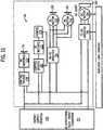
- FIGS. 1 and 2illustrates an auxiliary drive circuit 10 that includes an auxiliary system or load 102 coupled to an auxiliary link or auxiliary bus positive bus 103.
- the auxiliary load 102is powered by a battery 104 coupled to a first DC link or bus 105, having a positive DC link 111 and a negative DC link 113.
- Battery 104is coupled to first DC bus 105.
- battery 104may be replaced by a fuel cell.
- a first bi-directional buck/boost converter 106is coupled between first DC bus 105, which is a low-voltage side of the converter 106, and a second DC link or bus 110 which is a high-voltage side of the converter 106, having a positive DC link 115 and negative DC link 117.
- First bi-directional buck/boost converter 106converts the electrical power that is coupled on the low-voltage side from battery 104 onto first DC bus 105 to a first voltage and outputs the first voltage to second DC bus 110.
- a buck converter 108has a high-voltage side coupled to second DC bus 110, and a low-voltage side coupled to auxiliary bus 103. Buck converter 108 converts the first voltage on the high-voltage side, coupled to second DC bus 110, to a second voltage on the low-voltage side and outputs the second voltage to auxiliary bus 103 which supplies the second voltage to auxiliary load 102.
- First DC bus 105includes contactors 112, 114 to permit galvanic isolation of battery 104 from the remainder of circuit 10.
- a double pole single throw (DPST) switchmay be implemented with contactors 112, 114 to facilitate isolation of battery 104.
- contactors 112 and 114may be replaced by semiconductor switches or similar devices capable of coupling and decoupling battery 104 to circuit 10.
- Semiconductor switches or similar devicesare capable of decoupling a source from a load with very high impedance, typically measured in at least tens of megohms.
- Contactors 112, 114could also be replaced by diodes in another example of the disclosure.
- bi-directional buck/boost converter 106boosts or steps up the voltage from battery 104 to a higher voltage that is output to second DC bus 110.
- Buck converter 108takes the voltage output by bi-directional buck/boost converter 106 and, typically, steps down the voltage to a level where auxiliary load 102 can operate more efficiently.
- Auxiliary system 102 voltageis decoupled from second DC bus 110 by buck converter 108 and can be operated at a selected voltage below the second DC bus 110 voltage.
- each load 102may have a control device 109 (shown in phantom and described in detail in FIG. 11 ), such as a DC-to-AC inverter or DC-to-DC converter, configured to further adjust the input voltage to a level most suitable for the individual load.
- the level to which the battery 104 voltage(i.e., the voltage on the first DC bus) is stepped up by bi-directional buck/boost converter 106 depends on the manner in which the converter 106 is controlled.
- the level to which the bi-directional buck/boost converter high-voltage side(i.e., the voltage on the second DC bus 110) is stepped down by buck converter 108 depends on the manner in which buck converter 108 is controlled.
- FIG. 3shows an example of a switch-mode power supply: a bi-directional buck/boost converter 106 having two transistors or switches 202, 204 used to control the voltage difference between the low-voltage side and the high-voltage side of the device.
- a microprocessor-based energy management system (EMS), or controller, 116(shown in FIG. 1 ) opens and closes switches 202, 204 using pulse-width modulation (PWM) to generate the desired output voltage.
- PWMpulse-width modulation
- a second switch-mode power supplysuch as buck converter 108 shown in FIG. 4 has a voltage at the low-voltage side 210 that can be controlled by a switching of transistor 208 by EMS/controller 116 (shown in FIG.
- Pulse-width modulation of a power sourcesuch as battery 104 and bi-directional buck/boost converter 106 or buck converter 108, involves modulation of the power source duty cycle.
- the resulting outputis a series of square waves. By controlling the timing of the square waves, the power source output signal can be made to simulate a range of DC voltage values.
- Microprocessor-based EMS/controller 116is configured to optimize the operating efficiency of auxiliary load 102 by dynamically setting the auxiliary load control device input voltage based on a set of external factors.
- EMS 116can communicate with the auxiliary load control device 109 to command the voltage, if the auxiliary load is a DC auxiliary load, or both voltage and frequency, if the auxiliary load is an AC auxiliary load, for auxiliary system 102 during vehicle operation.
- EMS 116may communicate with the auxiliary load control device 109 to command the frequency and voltage of the specific motors that drive the auxiliary systems using measured values including, but not limited to, ambient temperature, coolant temperature, traction drive power and torque levels, vehicle speed, vehicle acceleration/deceleration rate, vehicle operating mode, and road gradient.
- the auxiliary drive circuit 20 illustrated in FIGS. 5 and 6is based on the circuit 10 of FIGS. 1 and 2 and replaces the buck converter 108 (in FIG. 2 ) by a second bi-directional buck/boost converter 120 and includes a coupling device 122 coupled between the positive DC Link 111 of first DC bus 105 and auxiliary bus positive bus 103.
- An alternate example of circuit 20includes a pre-charge resistor 119 and a single pole single throw (SPST) contactor 121 (shown in phantom) connected in parallel. Pre-charge resistor 119 and SPST contactor 121 are coupled between contactor 112 and first bi-directional buck/boost converter 106.
- a pre-charge configurationcouples a pre-charge resistor such as pre-charge resistor 119 and an SPST contactor such as SPST contactor 121, or appropriate semiconductor switch, in series wherein both of these series connected components 119, 121 are coupled in parallel with contactor 112.
- Coupling device 122may be one of a diode, contactor, or semiconductor switch.
- Second bi-directional buck/boost converter 120decouples auxiliary system 102 voltage from second DC bus 110 and is configured to convert a first voltage from second DC bus 110 into a second voltage that is output to auxiliary bus 103. The conversion generates an auxiliary bus 103 voltage that is less than the second DC bus 110 voltage.
- auxiliary system 102can operate efficiently at the battery 104 voltage, the system 102 can be powered directly from battery 104 through coupling device 122, thus bypassing the second bi-directional buck/boost converter 120, which receives power from battery 104 voltage via second DC bus 110, and bypassing first bi-directional buck/boost converter 106.
- a pre-charge circuit(not shown) may be employed during start up of auxiliary loads, auxiliary control devices, and bi-directional buck/boost converters.
- battery 104can be replaced by a fuel cell in an alternate example of the disclosure. Alternate examples are envisioned in which first and second bi-directional buck/boost converters 106, 120 simultaneously supply power to second DC bus 110, effectively doubling the power available to devices powered therefrom.
- first and second bi-directional buck/boost converters 106, 120(and buck converter 108 in FIG. 2 ) enables the system 20 to power auxiliary load 102 directly from energy captured during regenerative braking.
- battery 104may not have to supply any power to the auxiliary system 102, further improving system efficiency.
- the voltage generated during regenerative brakingmay exceed the battery 104 voltage, and could be used to provide power to partially charge battery 104 and to operate auxiliary system 102.
- the typically increased voltage from regenerative brakingmay increase the second DC bus 110 voltage to a level greater than the maximum allowable voltage of battery 104.
- auxiliary bus 103may be greater than the voltage on first DC bus 105, allowing operation of cooling fans at higher speeds than when operated from battery 104 DC via first DC bus 105.
- fansprovide additional cooling using regenerative braking energy without taxing battery 104.
- auxiliary DC bus 103is operated at a higher voltage than the voltage output by battery 104, additional regenerative energy is utilized and therefore less regenerative braking energy is wasted in dynamic brake grids (not shown), or dissipated in a mechanical brake or other power dissipating device (not shown).
- the auxiliary drive circuit 30 illustrated in FIGS. 7 and 8is based on the circuit 20 shown in FIGS. 5 and 6 and adds a third bi-directional buck/boost converter 124, a second coupling device 126, and a second energy storage device 128.
- Third bi-directional buck/boost converter 124which is configured to be controlled by EMS 116, is coupled between second DC bus 110 and second energy storage device 128.
- Second energy storage device 128can be charged directly from battery 104 through coupling devices 122, 126 or from second DC bus 110 through third bi-directional buck/boost converter 124.
- the second DC bus 110 voltage(high-voltage side) is determined by the voltage from first bi-directional buck/boost converter 106 and, depending on the state of coupling device 122, possibly from the second bi-directional buck/boost converter 120, or associated traction drive(s) (not shown) or other loads/sources (not shown) that may be attached to the high-voltage side of second DC link 110.
- Second energy storage device 128,which may be one of a battery and an ultracapacitor, can also supply power to second DC bus 110 through third bi-directional buck/boost converter 124, or to auxiliary load 102 through second and third bi-directional buck/boost converters 120 and 124.
- a third energy storage device 130may be coupled across second DC bus 110.
- Third energy storage device 130which may be one of a battery and an ultracapacitor, can supply power directly to second DC bus 110, to battery 104 through first bi-directional buck/boost converter 106, to auxiliary load 102 through second bi-directional buck/boost converter 120, or to energy storage device 128 through third bi-directional buck/boost converter 124.
- FIGS. 9 and 10illustrate an auxiliary drive circuit 40 based on circuit 30 shown in FIGS. 7 and 8 and includes a plurality of fuel cells 132 and a plurality of coupling devices 134, each of which may be one of a diode, a contactor and a semiconductor switch.
- the plurality of fuels cells 132are configured to supply electrical power directly to auxiliary system 102, to second DC bus 110 through second bi-directional buck/boost converter 120, to battery 104 either through first bi-directional buck/boost converter 106, or possibly to second energy storage device 128 through coupling device 126 or through third bi-directional buck/boost converter 124.
- FIG. 11illustrates an example of an auxiliary drive system 50 having multiple auxiliary loads, which receive electrical power from one or more energy supply devices 150 through a bi-directional buck/boost converter 151.
- the multiple auxiliary loadsinclude three AC motors 152, 154 and 156.
- AC motors 152 and 154drive fans 158 and 160, respectively.
- AC motor 156drives an air conditioning compressor 162.
- AC poweris supplied to motors 152, 154 and 156 via two DC-to-AC inverters 164, 166.
- System 50also includes two DC motors 170, 172.
- DC motor 170drives a fan 174 while DC motor 172 drives a pump 176.
- DC poweris supplied to motors 170, 172 via control devices 178, 180, which may include one of a DC-to-DC converter, a thermo-switch, a flow sensor, and a pressure switch.
- control devices 178, 180 and DC-to-AC inverters 164, 166may be configured to independently control the voltage input to their respective auxiliary loads. For example, if the vehicle or system is operating at low power levels, the DC motors 170, 172, which run the fan 174 and pump 176, are likewise operating at very low speeds.
- an auxiliary drive circuitincluding a first energy storage device coupled to a first DC bus and configured to output electrical power to the first DC bus, and a first DC-to-DC voltage converter coupled to the first DC bus and to a second DC bus, the first DC-to-DC voltage converter configured to convert the electrical power to a first voltage and to output the first voltage to the second DC bus.
- the auxiliary drive circuitalso includes a second DC-to-DC voltage converter coupled to the second DC bus and coupled to an auxiliary bus, the second DC-to-DC voltage converter configured to convert the first voltage to a second voltage and to provide the second voltage to the auxiliary bus, the auxiliary bus configured to provide an auxiliary voltage to an auxiliary load, wherein the second voltage is different from the first voltage.
- a method of manufacturingincludes coupling a first energy storage device to a first DC link, the first energy device configured to output electrical power to the first DC link, coupling a first switch-mode power supply to the first DC link and to a second DC link, and configuring the first switch-mode power supply to convert the electrical power output by the first energy storage device to the first DC link into a first voltage, and to output the first voltage to the second DC link.
- the methodalso includes coupling a second switch-mode power supply to the second DC link and to an auxiliary bus, and configuring the second switch-mode power supply to convert the first voltage to a second voltage and to supply the second voltage to the auxiliary bus, wherein the second voltage is different from the first voltage.
- an auxiliary drive systemincluding a first energy storage device coupled to a first DC bus, the first energy storage device configured to output electrical power to the first DC bus, a first bi-directional buck/boost converter coupled to a second DC bus and to the first DC bus, the first bi-directional buck/boost converter configured to output a first voltage to the second DC bus, a voltage converter coupled between an auxiliary bus and the second DC bus, the voltage converter configured to convert the first voltage to a second voltage different from the first voltage, the second voltage output to the auxiliary bus.
- the auxiliary drive systemfurther includes an auxiliary system coupled to the auxiliary bus, and configured to receive an input voltage from the auxiliary bus, and a controller configured to regulate the first voltage output from the first bi-directional buck/boost converter, and further configured to regulate the second voltage output from the voltage converter.
Landscapes
- Engineering & Computer Science (AREA)
- Power Engineering (AREA)
- Mechanical Engineering (AREA)
- Transportation (AREA)
- Sustainable Energy (AREA)
- Life Sciences & Earth Sciences (AREA)
- Sustainable Development (AREA)
- Chemical & Material Sciences (AREA)
- Combustion & Propulsion (AREA)
- Automation & Control Theory (AREA)
- Electric Propulsion And Braking For Vehicles (AREA)
- Charge And Discharge Circuits For Batteries Or The Like (AREA)
- Dc-Dc Converters (AREA)
Description
- The disclosure relates generally to hybrid and electric vehicles, and more specifically to systems for operating auxiliary systems aboard hybrid and electric vehicles.
- Purely electric vehicles typically use stored electrical energy to power an electric motor, which propels the vehicle. Hybrid electric vehicles combine an internal combustion engine and an electric motor that is typically powered by one or more electrical energy storage devices. Such a combination may increase overall fuel efficiency by enabling the combustion engine and the electric motor to each operate in respective ranges of increased efficiency. Electric motors, for example, may be efficient at accelerating from a standing start, while combustion engines may be efficient during sustained periods of constant engine operation, such as in highway driving. Having an electric motor to boost initial acceleration allows combustion engines in hybrid vehicles to be smaller and more fuel efficient.
- In conventional vehicles, auxiliary systems include air conditioning, power steering pumps, oil pumps, coolant fans and air compressors, and the like, and are typically driven by belts and gear drives powered by the vehicle's internal combustion engine. However, electric and hybrid vehicles generally power auxiliary systems using stored or recaptured electrical energy. In some cases, for example, such as a transit bus operating in an urban area, energy required to operate auxiliary system loads may exceed the energy needed to propel the vehicle. Efficiency improvements in the operation of auxiliary systems may increase the driving range of electric vehicles and may reduce fuel usage and tail pipe emissions in hybrid vehicles.
US 2002/109406 A1 describes an apparatus for generating and distributing electrical power in a vehicle. A voltage network is connected to a bi-directional DC/DC converter which is connected to a second voltage network which has a lower voltage rating than the first network. The second voltage network is connected to a second DC/DC converter which is connected to a third voltage network with a lower rated voltage than the second voltage network and connected to a second energy store.US 2001/053950 A1 describes a fuel cell vehicle in which it is determined whether a terminal voltage of a power storage unit is higher than a predetermined value. - Auxiliary systems in hybrid and electric vehicles may be powered directly from a battery, fuel cell, or other energy storage device, or may be powered through the traction drive DC link. One auxiliary system may run most efficiently at a voltage different from that needed for efficient operation of another auxiliary system. However, one common system design may cause the auxiliary systems to run at a voltage provided by the fuel cell or battery supplying power thereto even if the provided voltage is not ideal for a specific auxiliary system. Moreover, the voltage provided by such a battery or fuel cell may vary widely with the load placed thereon. As a result, some auxiliary systems may waste power by operating inefficiently at widely varying or suboptimal voltages. It would therefore be desirable to have a system capable of supplying stable power to a plurality of auxiliary systems at a voltage where each system operates most efficiently
- Aspects of the invention are defined in the appended claims.
- Various other features and advantages will be made apparent from the following detailed description and the drawings.
- The drawings illustrate one preferred example presently contemplated for carrying out the disclosure.
- In the drawings:
FIG. 1 is a schematic diagram of an auxiliary drive circuit according to an example of the disclosure.FIG. 2 is a schematic diagram of an auxiliary drive circuit according to an example of the disclosure.FIG. 3 is a schematic diagram of an exemplary bi-directional buck/boost converter according to an example of the disclosure.FIG. 4 is a schematic diagram of an exemplary buck converter according to an example of the disclosure.FIG. 5 is a schematic diagram of an auxiliary drive circuit according to an example of the disclosure.FIG. 6 is a schematic diagram of an auxiliary drive circuit according to an example of the disclosure.FIG. 7 is a schematic diagram of an auxiliary drive circuit according to an example of the disclosure.FIG. 8 is a schematic diagram of an auxiliary drive circuit according to an example of the disclosure.FIG. 9 is a schematic diagram of an auxiliary drive circuit according to an example of the disclosure.FIG. 10 is a schematic diagram of an auxiliary drive circuit according to an example of the disclosure.FIG. 11 is a schematic diagram of an auxiliary drive circuit having multiple auxiliary loads according to an example of the disclosure.- The disclosure includes examples that relate to hybrid and electric vehicles. The disclosure includes examples that relate to an auxiliary drive apparatus and to methods for manufacturing auxiliary drive systems.
- An example of the disclosure illustrated in
FIGS. 1 and2 illustrates anauxiliary drive circuit 10 that includes an auxiliary system orload 102 coupled to an auxiliary link or auxiliary buspositive bus 103. Theauxiliary load 102 is powered by abattery 104 coupled to a first DC link orbus 105, having apositive DC link 111 and anegative DC link 113.Battery 104 is coupled tofirst DC bus 105. In an alternate example,battery 104 may be replaced by a fuel cell. A first bi-directional buck/boost converter 106 is coupled betweenfirst DC bus 105, which is a low-voltage side of theconverter 106, and a second DC link orbus 110 which is a high-voltage side of theconverter 106, having apositive DC link 115 andnegative DC link 117. First bi-directional buck/boost converter 106 converts the electrical power that is coupled on the low-voltage side frombattery 104 ontofirst DC bus 105 to a first voltage and outputs the first voltage tosecond DC bus 110. Abuck converter 108 has a high-voltage side coupled tosecond DC bus 110, and a low-voltage side coupled toauxiliary bus 103.Buck converter 108 converts the first voltage on the high-voltage side, coupled tosecond DC bus 110, to a second voltage on the low-voltage side and outputs the second voltage toauxiliary bus 103 which supplies the second voltage toauxiliary load 102. First DC bus 105 includescontactors battery 104 from the remainder ofcircuit 10. In one example, a double pole single throw (DPST) switch may be implemented withcontactors battery 104. In an alternate example,contactors battery 104 tocircuit 10. Semiconductor switches or similar devices are capable of decoupling a source from a load with very high impedance, typically measured in at least tens of megohms.Contactors boost converter 106 boosts or steps up the voltage frombattery 104 to a higher voltage that is output tosecond DC bus 110.Buck converter 108 takes the voltage output by bi-directional buck/boost converter 106 and, typically, steps down the voltage to a level whereauxiliary load 102 can operate more efficiently.Auxiliary system 102 voltage is decoupled fromsecond DC bus 110 bybuck converter 108 and can be operated at a selected voltage below thesecond DC bus 110 voltage. Additionally, if there are multipleauxiliary loads 102, eachload 102 may have a control device 109 (shown in phantom and described in detail inFIG. 11 ), such as a DC-to-AC inverter or DC-to-DC converter, configured to further adjust the input voltage to a level most suitable for the individual load.- The level to which the
battery 104 voltage (i.e., the voltage on the first DC bus) is stepped up by bi-directional buck/boost converter 106 depends on the manner in which theconverter 106 is controlled. Similarly, the level to which the bi-directional buck/boost converter high-voltage side (i.e., the voltage on the second DC bus 110) is stepped down bybuck converter 108 depends on the manner in whichbuck converter 108 is controlled. FIG. 3 shows an example of a switch-mode power supply: a bi-directional buck/boost converter 106 having two transistors orswitches FIG. 1 ) opens and closesswitches buck converter 108 shown inFIG. 4 has a voltage at the low-voltage side 210 that can be controlled by a switching oftransistor 208 by EMS/controller 116 (shown inFIG. 1 ) using PWM. Pulse-width modulation of a power source, such asbattery 104 and bi-directional buck/boost converter 106 orbuck converter 108, involves modulation of the power source duty cycle. The resulting output is a series of square waves. By controlling the timing of the square waves, the power source output signal can be made to simulate a range of DC voltage values.- Microprocessor-based EMS/
controller 116 is configured to optimize the operating efficiency ofauxiliary load 102 by dynamically setting the auxiliary load control device input voltage based on a set of external factors.EMS 116 can communicate with the auxiliaryload control device 109 to command the voltage, if the auxiliary load is a DC auxiliary load, or both voltage and frequency, if the auxiliary load is an AC auxiliary load, forauxiliary system 102 during vehicle operation.EMS 116 may communicate with the auxiliaryload control device 109 to command the frequency and voltage of the specific motors that drive the auxiliary systems using measured values including, but not limited to, ambient temperature, coolant temperature, traction drive power and torque levels, vehicle speed, vehicle acceleration/deceleration rate, vehicle operating mode, and road gradient. - The
auxiliary drive circuit 20 illustrated inFIGS. 5 and6 is based on thecircuit 10 ofFIGS. 1 and2 and replaces the buck converter 108 (inFIG. 2 ) by a second bi-directional buck/boost converter 120 and includes acoupling device 122 coupled between thepositive DC Link 111 offirst DC bus 105 and auxiliary buspositive bus 103. An alternate example ofcircuit 20 includes apre-charge resistor 119 and a single pole single throw (SPST) contactor 121 (shown in phantom) connected in parallel.Pre-charge resistor 119 and SPST contactor 121 are coupled betweencontactor 112 and first bi-directional buck/boost converter 106. In an alternate example, a pre-charge configuration (not shown) couples a pre-charge resistor such aspre-charge resistor 119 and an SPST contactor such as SPST contactor 121, or appropriate semiconductor switch, in series wherein both of these series connectedcomponents 119, 121 are coupled in parallel withcontactor 112.Coupling device 122 may be one of a diode, contactor, or semiconductor switch. Second bi-directional buck/boost converter 120 decouplesauxiliary system 102 voltage fromsecond DC bus 110 and is configured to convert a first voltage fromsecond DC bus 110 into a second voltage that is output toauxiliary bus 103. The conversion generates anauxiliary bus 103 voltage that is less than thesecond DC bus 110 voltage. However, ifauxiliary system 102 can operate efficiently at thebattery 104 voltage, thesystem 102 can be powered directly frombattery 104 throughcoupling device 122, thus bypassing the second bi-directional buck/boost converter 120, which receives power frombattery 104 voltage viasecond DC bus 110, and bypassing first bi-directional buck/boost converter 106. A pre-charge circuit (not shown) may be employed during start up of auxiliary loads, auxiliary control devices, and bi-directional buck/boost converters. As in the example ofFIGS. 1 and2 described above,battery 104 can be replaced by a fuel cell in an alternate example of the disclosure. Alternate examples are envisioned in which first and second bi-directional buck/boost converters second DC bus 110, effectively doubling the power available to devices powered therefrom. - The ability to control the voltage output of first and second bi-directional buck/
boost converters 106, 120 (andbuck converter 108 inFIG. 2 ) enables thesystem 20 to powerauxiliary load 102 directly from energy captured during regenerative braking. During regenerative braking,battery 104 may not have to supply any power to theauxiliary system 102, further improving system efficiency. Additionally, it is possible that the voltage generated during regenerative braking may exceed thebattery 104 voltage, and could be used to provide power to partially chargebattery 104 and to operateauxiliary system 102. During severe braking or while holding speed on a downhill grade, the typically increased voltage from regenerative braking may increase thesecond DC bus 110 voltage to a level greater than the maximum allowable voltage ofbattery 104. Thus the voltage onauxiliary bus 103 may be greater than the voltage onfirst DC bus 105, allowing operation of cooling fans at higher speeds than when operated frombattery 104 DC viafirst DC bus 105. As a result, fans provide additional cooling using regenerative braking energy without taxingbattery 104. In addition, during severe regenerative braking events, when theauxiliary DC bus 103 is operated at a higher voltage than the voltage output bybattery 104, additional regenerative energy is utilized and therefore less regenerative braking energy is wasted in dynamic brake grids (not shown), or dissipated in a mechanical brake or other power dissipating device (not shown). - The
auxiliary drive circuit 30 illustrated inFIGS. 7 and8 is based on thecircuit 20 shown inFIGS. 5 and6 and adds a third bi-directional buck/boost converter 124, asecond coupling device 126, and a secondenergy storage device 128. Third bi-directional buck/boost converter 124, which is configured to be controlled byEMS 116, is coupled betweensecond DC bus 110 and secondenergy storage device 128. Secondenergy storage device 128 can be charged directly frombattery 104 throughcoupling devices second DC bus 110 through third bi-directional buck/boost converter 124. Thesecond DC bus 110 voltage (high-voltage side) is determined by the voltage from first bi-directional buck/boost converter 106 and, depending on the state ofcoupling device 122, possibly from the second bi-directional buck/boost converter 120, or associated traction drive(s) (not shown) or other loads/sources (not shown) that may be attached to the high-voltage side ofsecond DC link 110. Secondenergy storage device 128, which may be one of a battery and an ultracapacitor, can also supply power tosecond DC bus 110 through third bi-directional buck/boost converter 124, or toauxiliary load 102 through second and third bi-directional buck/boost converters - Still referring to
FIGS. 7 and8 , a third energy storage device 130 (shown in phantom) may be coupled acrosssecond DC bus 110. Thirdenergy storage device 130, which may be one of a battery and an ultracapacitor, can supply power directly tosecond DC bus 110, tobattery 104 through first bi-directional buck/boost converter 106, toauxiliary load 102 through second bi-directional buck/boost converter 120, or toenergy storage device 128 through third bi-directional buck/boost converter 124. FIGS. 9 and10 illustrate anauxiliary drive circuit 40 based oncircuit 30 shown inFIGS. 7 and8 and includes a plurality offuel cells 132 and a plurality ofcoupling devices 134, each of which may be one of a diode, a contactor and a semiconductor switch. The plurality offuels cells 132, each of which is coupled to aseparate coupling device 134, are configured to supply electrical power directly toauxiliary system 102, tosecond DC bus 110 through second bi-directional buck/boost converter 120, tobattery 104 either through first bi-directional buck/boost converter 106, or possibly to secondenergy storage device 128 throughcoupling device 126 or through third bi-directional buck/boost converter 124.FIG. 11 illustrates an example of anauxiliary drive system 50 having multiple auxiliary loads, which receive electrical power from one or moreenergy supply devices 150 through a bi-directional buck/boost converter 151. The multiple auxiliary loads include threeAC motors AC motors drive fans AC motor 156 drives anair conditioning compressor 162. AC power is supplied tomotors AC inverters System 50 also includes twoDC motors DC motor 170 drives a fan 174 while DC motor 172 drives apump 176. DC power is supplied tomotors control devices boost converter 151. Additionally,control devices AC inverters DC motors converter 151 to controldevices control devices motors control devices motors battery 104, which is at a relatively high voltage.- According to one example of the disclosure, an auxiliary drive circuit including a first energy storage device coupled to a first DC bus and configured to output electrical power to the first DC bus, and a first DC-to-DC voltage converter coupled to the first DC bus and to a second DC bus, the first DC-to-DC voltage converter configured to convert the electrical power to a first voltage and to output the first voltage to the second DC bus. The auxiliary drive circuit also includes a second DC-to-DC voltage converter coupled to the second DC bus and coupled to an auxiliary bus, the second DC-to-DC voltage converter configured to convert the first voltage to a second voltage and to provide the second voltage to the auxiliary bus, the auxiliary bus configured to provide an auxiliary voltage to an auxiliary load, wherein the second voltage is different from the first voltage.
- In accordance with another example of the disclosure, a method of manufacturing includes coupling a first energy storage device to a first DC link, the first energy device configured to output electrical power to the first DC link, coupling a first switch-mode power supply to the first DC link and to a second DC link, and configuring the first switch-mode power supply to convert the electrical power output by the first energy storage device to the first DC link into a first voltage, and to output the first voltage to the second DC link. The method also includes coupling a second switch-mode power supply to the second DC link and to an auxiliary bus, and configuring the second switch-mode power supply to convert the first voltage to a second voltage and to supply the second voltage to the auxiliary bus, wherein the second voltage is different from the first voltage.
- In accordance with yet another example of the disclosure, an auxiliary drive system including a first energy storage device coupled to a first DC bus, the first energy storage device configured to output electrical power to the first DC bus, a first bi-directional buck/boost converter coupled to a second DC bus and to the first DC bus, the first bi-directional buck/boost converter configured to output a first voltage to the second DC bus, a voltage converter coupled between an auxiliary bus and the second DC bus, the voltage converter configured to convert the first voltage to a second voltage different from the first voltage, the second voltage output to the auxiliary bus. The auxiliary drive system further includes an auxiliary system coupled to the auxiliary bus, and configured to receive an input voltage from the auxiliary bus, and a controller configured to regulate the first voltage output from the first bi-directional buck/boost converter, and further configured to regulate the second voltage output from the voltage converter.
Claims (11)
- An auxiliary drive circuit comprising:a first energy storage device (104) having an output voltage, the first energy storage device (104) being coupled to a first DC bus (105) and configured to output electrical power to the first DC bus (105);a first DC-to-DC voltage converter (106) coupled to the first DC bus (105) and to a second DC bus (110), the first DC-to-DC voltage converter (106) configured to convert the electrical power to a first voltage and to output the first voltage to the second DC bus (110); anda second DC-to-DC voltage converter (108, 120) coupled to the second DC bus (110) and coupled to an auxiliary bus (103), the second DC-to-DC voltage converter (108, 120) configured to convert the first voltage to a second voltage, and to provide the second voltage to the auxiliary bus (103), the auxiliary bus (103) configured to provide an auxiliary voltage to a plurality of auxiliary loads (102), wherein the second voltage is different from the first voltage, wherein
the second voltage is greater than the output voltage; Pcharacterised in that:
the auxiliary drive circuit comprises:an auxiliary drive system (50) including control devices (178, 180) and DC-to-AC inverters (164, 166) coupled to the auxiliary bus (103) and configured to independently control the voltage input to the plurality of auxiliary loads (102); anda controller in operable communication with the control devices, the controller being configured to:receive an input comprising a measured value of one or more parameters associated with operation of a vehicle in which the auxiliary drive circuit is incorporated; andprovide a command to command at least one of a frequency and voltage to drive at least one motor of the plurality of auxiliary loads based on the measured value of the one or more parameters at a higher operating efficiency of the plurality of auxiliary loads compared to an operating efficiency if the auxiliary drive was operated at the second voltage. - The auxiliary drive circuit of claim 1, further comprising a second energy storage device (128) coupled to the auxiliary bus (103) and to the second DC-to-DC voltage converter (108, 120), the second energy storage device (128) configured to supply electrical power to the auxiliary bus (103);
wherein the second DC-to-DC voltage converter (108, 120) is further configured to convert the electrical power supplied by the second energy storage device (128) to a third voltage and to provide the third voltage to the second DC bus (110). - The auxiliary drive circuit of claim 2, further comprising a coupling device (126) coupled between the second energy storage device (128) and the second DC-to-DC voltage converter (108, 120).
- The auxiliary drive circuit of any one of the preceding claims, further comprising a coupling device (122) coupled between the first energy storage device (104) and the first DC-to-DC voltage converter (106), wherein the coupling device (122) comprises one of a contactor, a semiconductor switch, and a diode.
- The auxiliary drive circuit of claim 4, wherein the coupling device (122) comprises a set of contactors configured to de-couple the positive and negative terminals of the first energy storage device (104) from the remainder of the auxiliary drive circuit.
- The auxiliary drive circuit of any one of the preceding claims, wherein the first DC-to-DC voltage converter (106) comprises a first bi-directional buck/boost converter.
- The auxiliary drive circuit of claim 6, wherein the second DC-to-DC voltage converter (120) comprises a second bi-directional buck/boost converter; and
further comprising a coupling device (122) coupled between the auxiliary bus (103) and the first DC bus (105). - The auxiliary drive circuit of any one of the preceding claims, wherein the auxiliary load (102) comprises one of a thermal switch, a DC motor, a control device, a DC-to-DC converter, a pump, a DC-AC inverter, an AC motor, and an air-conditioning motor.
- A method of manufacturing comprising:coupling a first energy storage device (104) having an output voltage to a first DC link (105), the first energy storage device (104) configured to output electrical power to the first DC link (105);coupling a first switch-mode power supply (106) to the first DC link (105) and to a second DC link (110);
configuring the first switch-mode power supply (106) to convert the electrical power output by the first energy storage device (104) to the first DC link (105) into a first voltage, and to output the first voltage to the second DC link (110);
coupling a second switch-mode power supply (108, 120) to the second DC link (110) and to an auxiliary bus (103);
configuring the second switch-mode power supply (108, 120) to convert the first voltage to a second voltage, and to supply the second voltage to the auxiliary bus (103); and
configuring the auxiliary bus (103) to provide an auxiliary voltage to a plurality of auxiliary loads (102),
wherein the second voltage is different from the first voltage,characterized by:the second voltage being greater than the output voltage;providing the auxiliary drive circuit with an auxiliary drive system (50) including control devices (178, 180) and DC-to-AC inverters (164, 166) coupled to the auxiliary bus (103);configuring the DC-to-AC inverters (164, 166) to independently control the voltage input to the plurality of auxiliary loads (102);providing a controller in operable communication with the control devices; and and configuring the controller to:receive an input comprising a measured value of one or more parameters associated with operation of a vehicle in which the auxiliary drive circuit is incorporated; andprovide a command to command at least one of a frequency and voltage to drive at least one motor of the plurality of auxiliary loads based on the measured value of the one or more parameters at a higher operating efficiency of the plurality of auxiliary loads compared to an operating efficiency if the auxiliary drive was operated at the second voltage. - The method of claim 9, further comprising controlling the output voltage of one of the first and the second switch-mode power supplies (106, 108, 120) using pulse-width-modulation.
- The method of one of claims 9 or 10, further comprising:providing a second energy storage device (128), the second energy storage device (128) comprising one of a battery and a fuel cell;configuring the second energy storage device (128) to supply electrical power to the auxiliary bus (103); andconfiguring the second energy storage device (128) to supply electrical power to the second DC link (110) via the second switch-mode power supply (108, 120).
Applications Claiming Priority (1)
| Application Number | Priority Date | Filing Date | Title |
|---|---|---|---|
| US12/326,152US8274173B2 (en) | 2008-12-02 | 2008-12-02 | Auxiliary drive apparatus and method of manufacturing same |
Publications (2)
| Publication Number | Publication Date |
|---|---|
| EP2193954A1 EP2193954A1 (en) | 2010-06-09 |
| EP2193954B1true EP2193954B1 (en) | 2020-10-21 |
Family
ID=41665664
Family Applications (1)
| Application Number | Title | Priority Date | Filing Date |
|---|---|---|---|
| EP09176593.3AActiveEP2193954B1 (en) | 2008-12-02 | 2009-11-20 | Auxiliary drive apparatus and method of manufacturing same |
Country Status (6)
| Country | Link |
|---|---|
| US (2) | US8274173B2 (en) |
| EP (1) | EP2193954B1 (en) |
| JP (2) | JP2010136614A (en) |
| KR (1) | KR101614948B1 (en) |
| CN (1) | CN101746247B (en) |
| ES (1) | ES2841051T3 (en) |
Families Citing this family (61)
| Publication number | Priority date | Publication date | Assignee | Title |
|---|---|---|---|---|
| JP4835743B2 (en)* | 2009-10-07 | 2011-12-14 | 株式会社デンソー | Control device for power conversion circuit |
| US8754545B2 (en)* | 2010-04-22 | 2014-06-17 | Trimble Navigation Limited | High efficiency backup-power circuits for switch-mode power supplies |
| JP5662410B2 (en)* | 2010-06-24 | 2015-01-28 | パナソニックIpマネジメント株式会社 | Electric vehicle power supply system |
| US8310083B2 (en)* | 2010-07-21 | 2012-11-13 | General Electric Company | Apparatus and system for power conversion |
| US10457159B1 (en)* | 2010-10-20 | 2019-10-29 | Motiv Power Systems, Inc. | Power share converter for connecting multiple energy storage systems |
| US9013066B2 (en) | 2010-10-28 | 2015-04-21 | Honeywell International Inc. | High voltage electric accumulators with internal distributed DC-DC converters for self regulation and protection |
| US20120112533A1 (en)* | 2010-11-09 | 2012-05-10 | Hitachi Automotive Products (Usa), Inc. | Power supply system for hybrid vehicle |
| US8761978B2 (en)* | 2011-03-23 | 2014-06-24 | General Electric Company | System for supplying propulsion energy from an auxiliary drive and method of making same |
| FR2977120B1 (en)* | 2011-06-24 | 2013-06-07 | Valeo Japan Co Ltd | PRINTED CIRCUIT BOARD FOR COMPRESSOR HOUSING |
| JP5790394B2 (en)* | 2011-10-14 | 2015-10-07 | トヨタ自動車株式会社 | Electric car |
| US9073438B2 (en) | 2011-10-28 | 2015-07-07 | General Electric Company | System for selectively coupling an energy source to a load and method of making same |
| CN103199708A (en)* | 2012-01-04 | 2013-07-10 | 台达电子企业管理(上海)有限公司 | High-voltage battery conversion system |
| FR2986917B1 (en)* | 2012-02-13 | 2014-02-21 | Converteam Technology Ltd | ELECTRIC POWER SUPPLY SYSTEM AND ELECTRIC POWER GENERATION PLANT COMPRISING SUCH A SYSTEM |
| HUP1200240A2 (en)* | 2012-04-21 | 2013-10-28 | Debreceni Egyetem | Circuit arrangement and method for ac traction control of electric vehicle |
| US8981727B2 (en) | 2012-05-21 | 2015-03-17 | General Electric Company | Method and apparatus for charging multiple energy storage devices |
| US9142372B2 (en)* | 2012-05-21 | 2015-09-22 | General Electric Company | Contactor isolation method and apparatus |
| US9013168B2 (en)* | 2012-06-07 | 2015-04-21 | General Electric Company | System for transferring energy from an energy source and method of making same |
| KR101235844B1 (en)* | 2012-07-16 | 2013-02-22 | (주)씨에스이 | Combined vacuum packaging machine for home and car |
| US9682691B2 (en)* | 2012-08-07 | 2017-06-20 | Ford Global Technologies, Llc | Initiating preparations for engine autostop prior to vehicle stop |
| SG2013067749A (en)* | 2012-09-07 | 2014-04-28 | Agency Science Tech & Res | An energy harvesting apparatus and a method for operating an energy harvesting apparatus |
| US9174525B2 (en) | 2013-02-25 | 2015-11-03 | Fairfield Manufacturing Company, Inc. | Hybrid electric vehicle |
| ES2638186T3 (en)* | 2013-03-27 | 2017-10-19 | Abb Technology Ag | Drive inverter shared by different engines in a vehicle |
| US10236803B2 (en) | 2014-06-02 | 2019-03-19 | Ford Global Technologies, Llc | Hybrid-vehicle variable-voltage traction motor drive |
| US9682671B2 (en)* | 2014-06-10 | 2017-06-20 | Ford Global Technologies, Llc | Vehicle system with battery boost and bypass control |
| US9716447B2 (en)* | 2014-06-18 | 2017-07-25 | Raytheon Company | Method and integrated motor drive power electronics system with improved efficiency |
| US9637006B2 (en)* | 2014-07-31 | 2017-05-02 | Caterpillar Inc. | Power converter for electric hybrid earthmoving machine |
| AU2015238862B2 (en)* | 2014-10-28 | 2019-11-14 | Ge Global Sourcing Llc | Blower system and method |
| CN105730257B (en) | 2014-12-08 | 2018-05-22 | 通用电气公司 | Propulsion system, Energy Management System and method |
| DE102015204491A1 (en)* | 2015-03-12 | 2016-09-15 | Robert Bosch Gmbh | A power buffer for a battery system for operating an electrical machine and method for adjusting an electrical power that can be provided by means of a battery system for operating an electrical machine |
| PE20180591A1 (en)* | 2015-07-10 | 2018-04-05 | Hemant Karamchand Rohera | HYBRID POWER BLOCK |
| WO2017058631A1 (en)* | 2015-09-30 | 2017-04-06 | Crynamt Management Llc | Converter architecture |
| US11456669B2 (en) | 2015-09-30 | 2022-09-27 | Apple Inc. | Voltage supply to a load and battery |
| US10974606B2 (en)* | 2016-08-31 | 2021-04-13 | Cps Technology Holdings Llc | Bi-stable relay |
| DE102016221514A1 (en)* | 2016-11-03 | 2018-05-03 | Audi Ag | Energy-technical coupling of a high-voltage on-board electrical system with a low voltage on-board electrical system |
| JP6397872B2 (en)* | 2016-11-04 | 2018-09-26 | 本田技研工業株式会社 | Power system |
| JP6397871B2 (en)* | 2016-11-04 | 2018-09-26 | 本田技研工業株式会社 | Power system |
| US10516189B2 (en)* | 2016-11-15 | 2019-12-24 | Ford Global Technologies, Llc | High voltage bus contactor fault detection |
| JP6446080B2 (en)* | 2017-03-10 | 2018-12-26 | 本田技研工業株式会社 | Power system |
| GB2561588B (en)* | 2017-04-19 | 2020-01-08 | Sevcon Ltd | DC-DC converter |
| JP6787242B2 (en)* | 2017-04-28 | 2020-11-18 | トヨタ自動車株式会社 | Power system |
| JP6545230B2 (en)* | 2017-08-31 | 2019-07-17 | 本田技研工業株式会社 | Vehicle power system |
| JP6554151B2 (en)* | 2017-08-31 | 2019-07-31 | 本田技研工業株式会社 | Vehicle power system |
| IT201700101020A1 (en)* | 2017-09-08 | 2019-03-08 | Magneti Marelli Spa | CONVERSION SYSTEM OF DC-DC TYPE ENERGY OPERATING BETWEEN A LOW VOLTAGE SYSTEM AND A HIGH VOLTAGE SYSTEM OF A VEHICLE INCLUDING AN ENERGY RECOVERY STAGE AND ITS PROCEDURE |
| IT201700101028A1 (en)* | 2017-09-08 | 2019-03-08 | Magneti Marelli Spa | BIDIRECTIONAL ENERGY CONVERSION SYSTEM OF DC-DC TYPE OPERATING BETWEEN A LOW VOLTAGE SYSTEM AND A HIGH VOLTAGE SYSTEM OF A VEHICLE INCLUDING A STAGE OF ENERGY RECOVERY AND ITS PROCEDURE |
| US10651648B2 (en) | 2018-01-11 | 2020-05-12 | General Electric Company | System for powering auxiliary loads of an energy storage system |
| US10581363B2 (en) | 2018-06-22 | 2020-03-03 | Ford Global Technologies, Llc | Isolated dual bus hybrid vehicle drivetrain |
| US11307225B2 (en) | 2018-09-24 | 2022-04-19 | Ford Global Technologies, Llc | Temperature based control of variable voltage converter |
| WO2020112832A1 (en)* | 2018-11-29 | 2020-06-04 | Club Car, Llc | Auxiliary power output for battery management system |
| US10742242B1 (en)* | 2019-06-05 | 2020-08-11 | Silicon Laboratories Inc. | Apparatus for improving the effective performance of a power source and associated methods |
| US11235676B2 (en)* | 2019-06-19 | 2022-02-01 | Karma Automotive Llc | Combined converter circuit |
| WO2021115576A1 (en)* | 2019-12-10 | 2021-06-17 | Abb Schweiz Ag | Vehicular power supply system |
| US11513578B1 (en)* | 2020-02-03 | 2022-11-29 | Meta Platforms Technologies, Llc | Power management system for an artificial reality system |
| GB2595711B (en)* | 2020-06-04 | 2022-10-19 | Advance Technical Systems Ltd | Power convertor |
| KR20220085934A (en)* | 2020-12-15 | 2022-06-23 | 현대모비스 주식회사 | Bidirectional insulating DC-DC converter and its control apparatus and operating method |
| KR102619173B1 (en)* | 2020-12-21 | 2024-01-03 | 현대모비스 주식회사 | Large capacity bidirectional insulating DC-DC converter and its control method |
| KR102528007B1 (en)* | 2020-12-21 | 2023-05-03 | 현대모비스 주식회사 | Large capacity bidirectional insulating DC-DC converter assembly and cooling structure thereof |
| CN115489387B (en)* | 2021-06-17 | 2024-10-11 | 比亚迪股份有限公司 | Energy conversion device, control method thereof and vehicle |
| US11876456B2 (en)* | 2021-12-08 | 2024-01-16 | Alpha And Omega Semiconductor International Lp | Switching regulator implementing power recycling |
| JP2023118207A (en)* | 2022-02-15 | 2023-08-25 | 日立建機株式会社 | Dump truck |
| US20240162827A1 (en)* | 2022-11-04 | 2024-05-16 | University Of North Texas | Multiple port bidirectional power conversion circuit |
| US12261531B2 (en) | 2022-12-13 | 2025-03-25 | Hamilton Sundstrand Corporation | Buck-boost converter for contactor drive |
Family Cites Families (27)
| Publication number | Priority date | Publication date | Assignee | Title |
|---|---|---|---|---|
| JPH0596928A (en) | 1991-10-11 | 1993-04-20 | Toyota Motor Corp | Automatic air-conditioning device for vehicle |
| JPH05184180A (en) | 1991-12-28 | 1993-07-23 | Stanley Electric Co Ltd | Motor controller |
| US5373195A (en)* | 1992-12-23 | 1994-12-13 | General Electric Company | Technique for decoupling the energy storage system voltage from the DC link voltage in AC electric drive systems |
| US5710699A (en)* | 1996-05-28 | 1998-01-20 | General Electric Company | Power electronic interface circuits for batteries and ultracapacitors in electric vehicles and battery storage systems |
| JPH10224912A (en) | 1997-02-07 | 1998-08-21 | Isuzu Motors Ltd | Electric car power supply device |
| US5903449A (en)* | 1998-06-09 | 1999-05-11 | General Electric Company | Bi-directional power control system for voltage converter |
| US6331365B1 (en)* | 1998-11-12 | 2001-12-18 | General Electric Company | Traction motor drive system |
| JP3842015B2 (en)* | 2000-06-12 | 2006-11-08 | 本田技研工業株式会社 | Idle control device for fuel cell vehicle |
| DE10102243A1 (en)* | 2001-01-19 | 2002-10-17 | Xcellsis Gmbh | Device for generating and distributing electrical energy to consumers in a vehicle |
| KR100768354B1 (en)* | 2001-02-16 | 2007-10-18 | 지멘스 악티엔게젤샤프트 | Automotive electrical systems |
| KR20030094002A (en)* | 2002-05-30 | 2003-12-11 | 엔이씨 도낀 가부시끼가이샤 | Hybrid power supply system |
| US7138730B2 (en)* | 2002-11-22 | 2006-11-21 | Virginia Tech Intellectual Properties, Inc. | Topologies for multiple energy sources |
| US7701079B2 (en)* | 2004-08-06 | 2010-04-20 | Continental Automotive Systems, Inc. | Automotive electrical system |
| JP2006278210A (en)* | 2005-03-30 | 2006-10-12 | Toyota Motor Corp | Failure diagnosis apparatus and failure diagnosis method |
| JP2006278297A (en) | 2005-03-30 | 2006-10-12 | Tdk Corp | Voltage conversion device, fuel cell power generation system, and power generation method |
| JP4555136B2 (en)* | 2005-03-31 | 2010-09-29 | 本田技研工業株式会社 | Fuel cell electrical system, fuel cell vehicle and power supply method |
| JP4519728B2 (en) | 2005-07-15 | 2010-08-04 | 本田技研工業株式会社 | Control device for electric vehicle |
| JP2007236064A (en)* | 2006-02-28 | 2007-09-13 | Daikin Ind Ltd | Energy storage device |
| US7392143B2 (en)* | 2006-03-14 | 2008-06-24 | The University Of Texas System Board Of Regents | Monitoring and fault diagnosis of single-and multi-converter power systems |
| JP2007302129A (en) | 2006-05-12 | 2007-11-22 | Toyota Motor Corp | Power supply for hybrid vehicles |
| JP4356715B2 (en)* | 2006-08-02 | 2009-11-04 | トヨタ自動車株式会社 | Power supply device and vehicle equipped with power supply device |
| JP4513812B2 (en) | 2007-01-04 | 2010-07-28 | トヨタ自動車株式会社 | Vehicle power supply device and vehicle |
| JP4569603B2 (en) | 2007-01-04 | 2010-10-27 | トヨタ自動車株式会社 | Power supply system, vehicle including the same, and control method thereof |
| JP2008289270A (en)* | 2007-05-17 | 2008-11-27 | Panasonic Corp | Power storage device |
| JP4874874B2 (en)* | 2007-06-06 | 2012-02-15 | トヨタ自動車株式会社 | Vehicle power supply |
| JP2009027886A (en)* | 2007-07-23 | 2009-02-05 | Sanken Electric Co Ltd | Ac-dc converter |
| US8058743B2 (en)* | 2008-09-30 | 2011-11-15 | GM Global Technology Operations LLC | Automotive electrical system for coupling power converters with a transformer |
- 2008
- 2008-12-02USUS12/326,152patent/US8274173B2/enactiveActive
- 2009
- 2009-11-20EPEP09176593.3Apatent/EP2193954B1/enactiveActive
- 2009-11-20ESES09176593Tpatent/ES2841051T3/enactiveActive
- 2009-12-01CNCN200910253369.2Apatent/CN101746247B/enactiveActive
- 2009-12-01KRKR1020090117742Apatent/KR101614948B1/enactiveActive
- 2009-12-01JPJP2009273096Apatent/JP2010136614A/enactivePending
- 2012
- 2012-08-07USUS13/568,251patent/US9061595B2/enactiveActive
- 2013
- 2013-10-07JPJP2013209761Apatent/JP5844787B2/enactiveActive
Non-Patent Citations (1)
| Title |
|---|
| None* |
Also Published As
| Publication number | Publication date |
|---|---|
| US8274173B2 (en) | 2012-09-25 |
| ES2841051T3 (en) | 2021-07-07 |
| JP2014042449A (en) | 2014-03-06 |
| US20100133912A1 (en) | 2010-06-03 |
| JP5844787B2 (en) | 2016-01-20 |
| KR20100062951A (en) | 2010-06-10 |
| CN101746247B (en) | 2016-01-06 |
| KR101614948B1 (en) | 2016-04-22 |
| US9061595B2 (en) | 2015-06-23 |
| JP2010136614A (en) | 2010-06-17 |
| EP2193954A1 (en) | 2010-06-09 |
| CN101746247A (en) | 2010-06-23 |
| US20120299378A1 (en) | 2012-11-29 |
Similar Documents
| Publication | Publication Date | Title |
|---|---|---|
| EP2193954B1 (en) | Auxiliary drive apparatus and method of manufacturing same | |
| JP6774519B2 (en) | Vehicle propulsion system with multi-channel DC bus and method of manufacturing the system | |
| JP3655277B2 (en) | Electric motor power management system | |
| EP1976721B1 (en) | Vehicle propulsion system | |
| US8245801B2 (en) | Expandable energy storage control system architecture | |
| US7960855B2 (en) | System and method for providing power control of an energy storage system | |
| US8761978B2 (en) | System for supplying propulsion energy from an auxiliary drive and method of making same | |
| US20110100735A1 (en) | Propulsion Energy Storage Control System and Method of Control | |
| US10044312B2 (en) | Modular stacked DC architecture traction system and method of making same | |
| JP2009508763A (en) | Plug-in hybrid propulsion power electronics equipment with high-speed energy storage device and control method and apparatus |
Legal Events
| Date | Code | Title | Description |
|---|---|---|---|
| PUAI | Public reference made under article 153(3) epc to a published international application that has entered the european phase | Free format text:ORIGINAL CODE: 0009012 | |
| AK | Designated contracting states | Kind code of ref document:A1 Designated state(s):AT BE BG CH CY CZ DE DK EE ES FI FR GB GR HR HU IE IS IT LI LT LU LV MC MK MT NL NO PL PT RO SE SI SK SM TR | |
| AX | Request for extension of the european patent | Extension state:AL BA RS | |
| 17P | Request for examination filed | Effective date:20101209 | |
| 17Q | First examination report despatched | Effective date:20110120 | |
| STAA | Information on the status of an ep patent application or granted ep patent | Free format text:STATUS: EXAMINATION IS IN PROGRESS | |
| REG | Reference to a national code | Ref country code:DE Ref legal event code:R079 Ref document number:602009062938 Country of ref document:DE Free format text:PREVIOUS MAIN CLASS: B60L0011180000 Ipc:B60L0001000000 | |
| GRAP | Despatch of communication of intention to grant a patent | Free format text:ORIGINAL CODE: EPIDOSNIGR1 | |
| STAA | Information on the status of an ep patent application or granted ep patent | Free format text:STATUS: GRANT OF PATENT IS INTENDED | |
| RIC1 | Information provided on ipc code assigned before grant | Ipc:B60L 1/00 20060101AFI20200514BHEP Ipc:H02M 3/158 20060101ALI20200514BHEP Ipc:B60L 50/51 20190101ALI20200514BHEP | |
| INTG | Intention to grant announced | Effective date:20200603 | |
| GRAS | Grant fee paid | Free format text:ORIGINAL CODE: EPIDOSNIGR3 | |
| GRAA | (expected) grant | Free format text:ORIGINAL CODE: 0009210 | |
| STAA | Information on the status of an ep patent application or granted ep patent | Free format text:STATUS: THE PATENT HAS BEEN GRANTED | |
| AK | Designated contracting states | Kind code of ref document:B1 Designated state(s):AT BE BG CH CY CZ DE DK EE ES FI FR GB GR HR HU IE IS IT LI LT LU LV MC MK MT NL NO PL PT RO SE SI SK SM TR | |
| REG | Reference to a national code | Ref country code:GB Ref legal event code:FG4D | |
| REG | Reference to a national code | Ref country code:CH Ref legal event code:EP | |
| REG | Reference to a national code | Ref country code:IE Ref legal event code:FG4D | |
| REG | Reference to a national code | Ref country code:DE Ref legal event code:R096 Ref document number:602009062938 Country of ref document:DE | |
| REG | Reference to a national code | Ref country code:AT Ref legal event code:REF Ref document number:1325490 Country of ref document:AT Kind code of ref document:T Effective date:20201115 | |
| REG | Reference to a national code | Ref country code:AT Ref legal event code:MK05 Ref document number:1325490 Country of ref document:AT Kind code of ref document:T Effective date:20201021 | |
| REG | Reference to a national code | Ref country code:NL Ref legal event code:MP Effective date:20201021 | |
| PG25 | Lapsed in a contracting state [announced via postgrant information from national office to epo] | Ref country code:GR Free format text:LAPSE BECAUSE OF FAILURE TO SUBMIT A TRANSLATION OF THE DESCRIPTION OR TO PAY THE FEE WITHIN THE PRESCRIBED TIME-LIMIT Effective date:20210122 Ref country code:FI Free format text:LAPSE BECAUSE OF FAILURE TO SUBMIT A TRANSLATION OF THE DESCRIPTION OR TO PAY THE FEE WITHIN THE PRESCRIBED TIME-LIMIT Effective date:20201021 Ref country code:NO Free format text:LAPSE BECAUSE OF FAILURE TO SUBMIT A TRANSLATION OF THE DESCRIPTION OR TO PAY THE FEE WITHIN THE PRESCRIBED TIME-LIMIT Effective date:20210121 Ref country code:PT Free format text:LAPSE BECAUSE OF FAILURE TO SUBMIT A TRANSLATION OF THE DESCRIPTION OR TO PAY THE FEE WITHIN THE PRESCRIBED TIME-LIMIT Effective date:20210222 Ref country code:NL Free format text:LAPSE BECAUSE OF FAILURE TO SUBMIT A TRANSLATION OF THE DESCRIPTION OR TO PAY THE FEE WITHIN THE PRESCRIBED TIME-LIMIT Effective date:20201021 | |
| REG | Reference to a national code | Ref country code:LT Ref legal event code:MG4D | |
| PG25 | Lapsed in a contracting state [announced via postgrant information from national office to epo] | Ref country code:SE Free format text:LAPSE BECAUSE OF FAILURE TO SUBMIT A TRANSLATION OF THE DESCRIPTION OR TO PAY THE FEE WITHIN THE PRESCRIBED TIME-LIMIT Effective date:20201021 Ref country code:PL Free format text:LAPSE BECAUSE OF FAILURE TO SUBMIT A TRANSLATION OF THE DESCRIPTION OR TO PAY THE FEE WITHIN THE PRESCRIBED TIME-LIMIT Effective date:20201021 Ref country code:LV Free format text:LAPSE BECAUSE OF FAILURE TO SUBMIT A TRANSLATION OF THE DESCRIPTION OR TO PAY THE FEE WITHIN THE PRESCRIBED TIME-LIMIT Effective date:20201021 Ref country code:BG Free format text:LAPSE BECAUSE OF FAILURE TO SUBMIT A TRANSLATION OF THE DESCRIPTION OR TO PAY THE FEE WITHIN THE PRESCRIBED TIME-LIMIT Effective date:20210121 Ref country code:AT Free format text:LAPSE BECAUSE OF FAILURE TO SUBMIT A TRANSLATION OF THE DESCRIPTION OR TO PAY THE FEE WITHIN THE PRESCRIBED TIME-LIMIT Effective date:20201021 Ref country code:IS Free format text:LAPSE BECAUSE OF FAILURE TO SUBMIT A TRANSLATION OF THE DESCRIPTION OR TO PAY THE FEE WITHIN THE PRESCRIBED TIME-LIMIT Effective date:20210221 | |
| PG25 | Lapsed in a contracting state [announced via postgrant information from national office to epo] | Ref country code:HR Free format text:LAPSE BECAUSE OF FAILURE TO SUBMIT A TRANSLATION OF THE DESCRIPTION OR TO PAY THE FEE WITHIN THE PRESCRIBED TIME-LIMIT Effective date:20201021 | |
| REG | Reference to a national code | Ref country code:CH Ref legal event code:PL | |
| REG | Reference to a national code | Ref country code:ES Ref legal event code:FG2A Ref document number:2841051 Country of ref document:ES Kind code of ref document:T3 Effective date:20210707 | |
| REG | Reference to a national code | Ref country code:DE Ref legal event code:R097 Ref document number:602009062938 Country of ref document:DE | |
| PG25 | Lapsed in a contracting state [announced via postgrant information from national office to epo] | Ref country code:LU Free format text:LAPSE BECAUSE OF NON-PAYMENT OF DUE FEES Effective date:20201120 Ref country code:MC Free format text:LAPSE BECAUSE OF FAILURE TO SUBMIT A TRANSLATION OF THE DESCRIPTION OR TO PAY THE FEE WITHIN THE PRESCRIBED TIME-LIMIT Effective date:20201021 Ref country code:LT Free format text:LAPSE BECAUSE OF FAILURE TO SUBMIT A TRANSLATION OF THE DESCRIPTION OR TO PAY THE FEE WITHIN THE PRESCRIBED TIME-LIMIT Effective date:20201021 Ref country code:CZ Free format text:LAPSE BECAUSE OF FAILURE TO SUBMIT A TRANSLATION OF THE DESCRIPTION OR TO PAY THE FEE WITHIN THE PRESCRIBED TIME-LIMIT Effective date:20201021 Ref country code:EE Free format text:LAPSE BECAUSE OF FAILURE TO SUBMIT A TRANSLATION OF THE DESCRIPTION OR TO PAY THE FEE WITHIN THE PRESCRIBED TIME-LIMIT Effective date:20201021 Ref country code:SK Free format text:LAPSE BECAUSE OF FAILURE TO SUBMIT A TRANSLATION OF THE DESCRIPTION OR TO PAY THE FEE WITHIN THE PRESCRIBED TIME-LIMIT Effective date:20201021 Ref country code:RO Free format text:LAPSE BECAUSE OF FAILURE TO SUBMIT A TRANSLATION OF THE DESCRIPTION OR TO PAY THE FEE WITHIN THE PRESCRIBED TIME-LIMIT Effective date:20201021 Ref country code:SM Free format text:LAPSE BECAUSE OF FAILURE TO SUBMIT A TRANSLATION OF THE DESCRIPTION OR TO PAY THE FEE WITHIN THE PRESCRIBED TIME-LIMIT Effective date:20201021 | |
| REG | Reference to a national code | Ref country code:BE Ref legal event code:MM Effective date:20201130 | |
| PLBE | No opposition filed within time limit | Free format text:ORIGINAL CODE: 0009261 | |
| STAA | Information on the status of an ep patent application or granted ep patent | Free format text:STATUS: NO OPPOSITION FILED WITHIN TIME LIMIT | |
| PG25 | Lapsed in a contracting state [announced via postgrant information from national office to epo] | Ref country code:LI Free format text:LAPSE BECAUSE OF NON-PAYMENT OF DUE FEES Effective date:20201130 Ref country code:DK Free format text:LAPSE BECAUSE OF FAILURE TO SUBMIT A TRANSLATION OF THE DESCRIPTION OR TO PAY THE FEE WITHIN THE PRESCRIBED TIME-LIMIT Effective date:20201021 Ref country code:CH Free format text:LAPSE BECAUSE OF NON-PAYMENT OF DUE FEES Effective date:20201130 | |
| 26N | No opposition filed | Effective date:20210722 | |
| PG25 | Lapsed in a contracting state [announced via postgrant information from national office to epo] | Ref country code:IE Free format text:LAPSE BECAUSE OF NON-PAYMENT OF DUE FEES Effective date:20201120 | |
| PG25 | Lapsed in a contracting state [announced via postgrant information from national office to epo] | Ref country code:SI Free format text:LAPSE BECAUSE OF FAILURE TO SUBMIT A TRANSLATION OF THE DESCRIPTION OR TO PAY THE FEE WITHIN THE PRESCRIBED TIME-LIMIT Effective date:20201021 | |
| PG25 | Lapsed in a contracting state [announced via postgrant information from national office to epo] | Ref country code:IS Free format text:LAPSE BECAUSE OF FAILURE TO SUBMIT A TRANSLATION OF THE DESCRIPTION OR TO PAY THE FEE WITHIN THE PRESCRIBED TIME-LIMIT Effective date:20210221 Ref country code:TR Free format text:LAPSE BECAUSE OF FAILURE TO SUBMIT A TRANSLATION OF THE DESCRIPTION OR TO PAY THE FEE WITHIN THE PRESCRIBED TIME-LIMIT Effective date:20201021 Ref country code:MT Free format text:LAPSE BECAUSE OF FAILURE TO SUBMIT A TRANSLATION OF THE DESCRIPTION OR TO PAY THE FEE WITHIN THE PRESCRIBED TIME-LIMIT Effective date:20201021 Ref country code:CY Free format text:LAPSE BECAUSE OF FAILURE TO SUBMIT A TRANSLATION OF THE DESCRIPTION OR TO PAY THE FEE WITHIN THE PRESCRIBED TIME-LIMIT Effective date:20201021 | |
| PG25 | Lapsed in a contracting state [announced via postgrant information from national office to epo] | Ref country code:MK Free format text:LAPSE BECAUSE OF FAILURE TO SUBMIT A TRANSLATION OF THE DESCRIPTION OR TO PAY THE FEE WITHIN THE PRESCRIBED TIME-LIMIT Effective date:20201021 | |
| PG25 | Lapsed in a contracting state [announced via postgrant information from national office to epo] | Ref country code:BE Free format text:LAPSE BECAUSE OF NON-PAYMENT OF DUE FEES Effective date:20201130 | |
| P01 | Opt-out of the competence of the unified patent court (upc) registered | Effective date:20230528 | |
| PGFP | Annual fee paid to national office [announced via postgrant information from national office to epo] | Ref country code:DE Payment date:20241022 Year of fee payment:16 | |
| PGFP | Annual fee paid to national office [announced via postgrant information from national office to epo] | Ref country code:GB Payment date:20241023 Year of fee payment:16 | |
| PGFP | Annual fee paid to national office [announced via postgrant information from national office to epo] | Ref country code:FR Payment date:20241022 Year of fee payment:16 | |
| PGFP | Annual fee paid to national office [announced via postgrant information from national office to epo] | Ref country code:ES Payment date:20241202 Year of fee payment:16 Ref country code:IT Payment date:20241022 Year of fee payment:16 |