EP2193500B1 - A caliper for measuring objects in an image - Google Patents
A caliper for measuring objects in an imageDownload PDFInfo
- Publication number
- EP2193500B1 EP2193500B1EP08807583.3AEP08807583AEP2193500B1EP 2193500 B1EP2193500 B1EP 2193500B1EP 08807583 AEP08807583 AEP 08807583AEP 2193500 B1EP2193500 B1EP 2193500B1
- Authority
- EP
- European Patent Office
- Prior art keywords
- caliper
- image data
- planar surface
- image
- data space
- Prior art date
- Legal status (The legal status is an assumption and is not a legal conclusion. Google has not performed a legal analysis and makes no representation as to the accuracy of the status listed.)
- Active
Links
Images


Classifications
- A—HUMAN NECESSITIES
- A61—MEDICAL OR VETERINARY SCIENCE; HYGIENE
- A61B—DIAGNOSIS; SURGERY; IDENTIFICATION
- A61B5/00—Measuring for diagnostic purposes; Identification of persons
- A61B5/103—Measuring devices for testing the shape, pattern, colour, size or movement of the body or parts thereof, for diagnostic purposes
- A61B5/107—Measuring physical dimensions, e.g. size of the entire body or parts thereof
- A61B5/1072—Measuring physical dimensions, e.g. size of the entire body or parts thereof measuring distances on the body, e.g. measuring length, height or thickness
- G—PHYSICS
- G06—COMPUTING OR CALCULATING; COUNTING
- G06T—IMAGE DATA PROCESSING OR GENERATION, IN GENERAL
- G06T19/00—Manipulating 3D models or images for computer graphics
- G—PHYSICS
- G06—COMPUTING OR CALCULATING; COUNTING
- G06T—IMAGE DATA PROCESSING OR GENERATION, IN GENERAL
- G06T7/00—Image analysis
- G06T7/0002—Inspection of images, e.g. flaw detection
- G06T7/0012—Biomedical image inspection
- G—PHYSICS
- G06—COMPUTING OR CALCULATING; COUNTING
- G06T—IMAGE DATA PROCESSING OR GENERATION, IN GENERAL
- G06T7/00—Image analysis
- G06T7/60—Analysis of geometric attributes
- G06T7/62—Analysis of geometric attributes of area, perimeter, diameter or volume
- G—PHYSICS
- G06—COMPUTING OR CALCULATING; COUNTING
- G06T—IMAGE DATA PROCESSING OR GENERATION, IN GENERAL
- G06T2219/00—Indexing scheme for manipulating 3D models or images for computer graphics
- G06T2219/012—Dimensioning, tolerancing
Definitions
- the inventionrelates to the field of image analysis and, more specifically, to measuring structures viewed in images.
- Computed Tomography (CT) colonoscopyalso known as virtual colonoscopy, is a technique for detecting polyps in the colon. Colon cancer is often preceded by the presence of a benign polyp before it becomes malignant. The size of a polyp is important because it helps predict the likelihood of malignancy. The measured size of a polyp in CT colonography images is used to determine the action a patient has to undergo after examination.
- CTComputed Tomography
- the polyp size on two-dimensional (2D) or three-dimensional (3D) colonography imagesmay be measured manually by measuring the distance between two points placed at two locations on the polyp base visualized in an image.
- the CT colonography softwarecomputes the Euclidean distance between the two points.
- each pointis placed on the colon wall somewhere halfway between the black (the colon air) and the white (the colon wall) gray value.
- the pointsare positioned directly on the visible colon surface.
- the polyp sizeis determined on the basis of the distance of the two points.
- a manual measurement technique for measuring the polyp sizeis described by P. J. Pickhardt et al.
- the polyp sizeis visualized by a line segment defined by the two points in a manual approach or floating inside the colon wall or in the air above the polyp in an automatic approach. This way of visualizing the measured polyp size does not always show the relationship between the measurement and the measured object.
- FIG. 1Aschematically illustrates a manually measured polyp size according to prior art.
- two points 101 and 102are selected on a contour 100 which is assumed to represent a projection of the polyp on a plane perpendicular to the viewing direction.
- the distance D1 between the selected two points 101 and 102is accepted as the size of the polyp.
- a side view 12 of the polypone can see that the distance D1 does not coincide with the size of the contour 100.
- Document WO 2005/022464 A1discloses a method for developing an executable template of an image processing protocol.
- the methodincludes placement of anatomical marks in a reference image and combining or joining the marks to define one or more geometric objects in the image.
- the protocolcan include the placement of labels specifying lengths or distances between marks or the defined geometrical objects.
- the documentdiscloses interactive 3D measurements, including 3D point-to-point distance line widget and thin cylindrical interactive rulers.
- the documentdiscloses as well a 3D interactive tool for volume approximation, wherein simple geometric shapes are used for volume approximation, comprising cuboids, ellipsoids and cylinders.
- a selected shapeis interactively placed and oriented in 3D by the user, so as to completely enclose a lesion.
- the document firtherdiscloses a tool for automatic measurement of the 3D extent of a pre-segmented lesion, the respective lengths of the principal directions being obtained by principal component analysis (PCA) of the segmented region.
- PCAprincipal component analysis
- a system for performing and visualizing a size measurement of an object viewed in an image computed from image datacomprising:
- the manipulations of the calipermay comprise translations, rotations and scaling of the caliper.
- Scaling of the calipermay be isotropic or directional.
- the manipulationsallow to better position the caliper relative to the object and may thus improve performing the size measurement, because it is easier to see what is being measured.
- the size of the object measured by the system of the inventionis often more accurate.
- Fig. 1Bschematically illustrates a manually measured polyp size according to the invention. In a top view 11, the first and second surface 211 of the caliper and 212, respectively, is adjacent to a contour 100 which is assumed to represent a projection of the polyp on a plane perpendicular to the viewing direction.
- the distance D2 between the two surfaces 211 and 212is accepted as the size of the polyp. This is in agreement with a definition of the polyp size described in an article by N. Gopalswamy et al., entitled “Is in vivo measurement of size of polyps during colonoscopy accurate?”, published in Gastrointestinal Endoscopy 46 (1997), no. 6, pages 497-502 .
- a side view 12further illustrates the distance D2 measured by the caliper of the invention.
- the first or second planar surfaceis semi-transparent.
- Semi-transparent planar surfacesallow viewing the object and other anatomical structures displayed in an image computed from the image data by the image unit through the first and second planar surface.
- the caliperfurther comprises a caliper axis.
- the caliper axismay be a rotation axis of the caliper.
- the caliper axismay further improve aligning the caliper with the measured object, in particular with an object having its own axis.
- the deployment unitis further arranged for aligning the caliper axis with an axis of the object. This makes aligning the caliper with an axis of the object, e.g., with a colon polyp axis, easier for the user of the system.
- the systemis used for measuring a colon polyp in a colonoscopic CT image.
- the systemhas proved very useful in test measurements of colon polyps in colonoscopic CT images.
- system according to the inventionis comprised in an image acquisition apparatus.
- system according to the inventionis comprised in a workstation.
- a method of performing and visualizing a size measurement of an object viewed in an image computed from image datacomprising:
- a computer program product to be loaded by a computer arrangementcomprising instructions for performing and visualizing a size measurement of an object viewed in an image computed from image data, the computer arrangement comprising a processing unit and a memory, the computer program product, after being loaded, providing said processing unit with the capability to carry out the following tasks:
- the systemmay be applied to view reports comprising multidimensional image data, e.g., 2-dimensional, 3-dimensional, or 4-dimensional images, acquired by various acquisition modalities such as, but not limited to, standard X-ray Imaging, Computed Tomography (CT), Magnetic Resonance Imaging (MRI), Ultrasound (US), Positron Emission Tomography (PET), Single Photon Emission Computed Tomography (SPECT), Digital Tomosynthesis, and Nuclear Medicine (NM).
- CTComputed Tomography
- MRIMagnetic Resonance Imaging
- USUltrasound
- PETPositron Emission Tomography
- SPECTSingle Photon Emission Computed Tomography
- NMNuclear Medicine
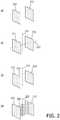
- FIG. 2illustrates exemplary embodiments of the caliper of the invention.
- a first embodiment 21 of the calipercomprises a first planar surface 211 and a second planar surface, substantially parallel to the first planar surface 212.
- the first and second planar surfaceare both a rectangle.
- the rectanglesare aligned with each other, i.e., the line determined by a pair of corresponding vertices of the first and second planar surface is substantially perpendicular to the first and second planar surface.
- the first and second planar surfacemay be a triangle or a circle.
- a circle of the first planar surfacemay have a radius different from, or may be not coaxial with, a circle of the second planar surface.
- a size of the objectis determined based on the distance between the planes of the first and second planar surface.
- a second embodiment 22 of the calipercomprises a first caliper axis 221 and a second caliper axis 222.
- the first caliper axis 221is substantially parallel to the first and second planar surface and placed substantially in the middle between the two planar surfaces.
- the second caliper axis 222is defined by the centers of the first and second planar surface.
- the first and/or second caliper axis 221 and/or 222, respectively,may or may not be visualized in an image.
- the first and second caliper axis 221 and/or 222, respectively,may be helpful in aligning the caliper with an anatomical or pathological structure such as a colon polyp.
- a third embodiment 23 of the calipercomprises a line segment 231.
- the ends of the line segment 231are the centers of the top sides of the rectangles of the first and second planar surface 211 and 212.
- the line segment 231is perpendicular to the first and second planar surface and may be useful for visualizing the size of the measured object.
- a fourth embodiment 24 of the calipercomprises a third rectangular surface 241 substantially perpendicular to the first and second planar surface.
- the vertices of this rectangleare the centers of the top and bottom side of the rectangles of the first and second planar surface.
- Fig. 3schematically shows a block diagram of an exemplary embodiment of the system 300 for performing and visualizing a measurement of an object viewed in an image computed from image data, the system comprising:
- the exemplary embodiment of the system 300further comprises the following units:
- the first input connector 381is arranged to receive data coming in from a data storage means such as, but not limited to, a hard disk, a magnetic tape, a flash memory, or an optical disk.
- the second input connector 382is arranged to receive data coming in from a user input device such as, but not limited to, a mouse or a touch screen.
- the third input connector 383is arranged to receive data coming in from a user input device such as a keyboard.
- the input connectors 381, 382 and 383are connected to an input control unit 380.
- the first output connector 391is arranged to output the data to a data storage means such as a hard disk, a magnetic tape, a flash memory, or an optical disk.
- the second output connector 392is arranged to output the data to a display device.
- the output connectors 391 and 392receive the respective data via an output control unit 390.
- the system 300comprises a memory unit 370.
- the system 300is arranged to receive input data from external devices via any of the input connectors 381, 382, and 383 and to store the received input data in the memory unit 370. Loading the input data into the memory unit 370 allows quick access to relevant data portions by the units of the system 300.
- the input datamay comprise, for example, the image data.
- the memory unit 370may be implemented by devices such as, but not limited to, a Random Access Memory (RAM) chip, a Read Only Memory (ROM) chip, and/or a hard disk drive and a hard disk.
- the memory unit 370may be further arranged to store the output data.
- the output datamay comprise, for example, data for displaying the caliper.
- the memory unit 370may be also arranged to receive data from and deliver data to the units of the system 300 comprising the image unit 310, the deployment unit 320, the manipulation unit 325, and the caliper unit 330, via a memory bus 375.
- the memory unit 370is further arranged to make the output data available to external devices via any of the output connectors 391 and 392. Storing data from the units of the system 300 in the memory unit 370 may advantageously improve performance of the units of the system 300 as well as the rate of transfer of the output data from the units of the system 300 to external devices.
- the system 300may comprise no memory unit 370 and no memory bus 375.
- the input data used by the system 300may be supplied by at least one external device, such as an external memory or a processor, connected to the units of the system 300.
- the output data produced by the system 300may be supplied to at least one external device, such as an external memory or a processor, connected to the units of the system 300.
- the units of the system 300may be arranged to receive the data from each other via internal connections or via a data bus.
- the image unit 310 of the system 300is arranged for visualizing the image data in the image for displaying on a display.
- the tasks to be performed by the image unit 310include, for example, determining a viewport for displaying the image.
- the skilled personwill know typical functions, which can be implemented in embodiments of the image unit 310.
- the viewmay be computed using, for example, maximum intensity projection (MIP), iso-surface projection (ISP), and direct volume rendering (DVR).
- MIPmaximum intensity projection
- ISPiso-surface projection
- DVRdirect volume rendering
- MIPa 3D location of maximum intensity along a projection ray is found.
- the rayis cast from a viewing plane.
- the intensity value of the pixel on the viewing planemay be set to the found maximum intensity value along the ray.
- ISPprojection rays are terminated when they cross the iso-surface of interest.
- the iso-surfaceis defined as the level set of the intensity function, i.e. the set of all voxels having the same intensity value.
- Objects such as iso-surfacesmay be identified in the image data and may be used to define objects in model coordinate systems of a graphics processor.
- a graphics pipeline of the graphics processormay be used to compute the view of the objects comprised in the model coordinate systems.
- the graphics pipelineis described in a book by J. D. Foley et al, entitled “Computer graphics: Principles and practice", 2nd Ed., Addison-Wesley, Reading, Massachusetts, USA, 1996 .
- the deployment unit 320 of the systemis arranged for deploying a caliper in an image data space.
- the caliperis deployed in a predefined location of the image data space or in a location specified by the user.
- the deployment unit 320may be arranged to receive a user input for specifying a caliper of a plurality of calipers for deployment.
- the deployment unit 320is arranged for segmenting the image data and deploying the caliper based on the image data segmentation.
- a method of segmenting, for example, a colon polypis described by J. J. Dijkers et al. in an article entitled “Segmentation and size measurement of polyps in ct colonography, published in "Medical image computing and computer-assisted intervention - MICCAI 2005, pt. 1, vol. 3749, 2005, pp. 712-719 , hereinafter referred to as Ref. 1.
- the size of the polypcan be also computed using the method described in Ref. 1.
- the deployment unit 320is arranged to determine the colon polyp axis based on the segmentation results and to align an axis of the caliper with the determined colon polyp axis.
- Ref. 1describes how to determine the colon polyp axis.
- the colon polyp axismay be defined by two points, the polyp mean point and the polyp center point.
- the polyp mean pointis computed by taking the mean of all points obtained in the polyp segmentation; the polyp center point is derived by minimizing the sum of distances of a point to all the surface normals.
- the deployment unit 320is further arranged to compute the size of the polyp and rotate and scale the aligned caliper based on the image data segmentation, using the method described in Ref. 1, for example.
- the optional manipulation unit 325is needed when measuring the size of the organ is performed manually.
- the manipulation unit 325is arranged to receive a user input from a user input device, such as a mouse, a trackball, or a keyboard, for example.
- the manipulation unitmay be further arranged to translate, rotate, and/or scale the caliper based on the user input.
- the manipulation unit 325is arranged for translating the caliper in the image data space.
- the manipulation unit 325is arranged to compute the translated location of the caliper on the basis of the user input.
- the translation vectorsare substantially parallel to the viewing plane.
- the usermay be also able to zoom in and out the caliper, when a perspective projection technique is used to compute the view of the region of the image data space.
- the manipulation unit 325is arranged for rotating the caliper in the image data space. Any number of rotation axes may be implemented.
- a rotation axismay be one of the three Cartesian axes of a reference system in the image data space. Alternatively, a rotation axis may be an axis of the caliper. For each rotation, a rotation axis and/or angle are selected by the user, and user input data specifying the rotation axis and/or angle is obtained by the manipulation unit 325.
- the manipulation unit 325is arranged for scaling the caliper by a scaling factor in a direction in the image data space.
- Scaling of the calipermay be isotropic or anisotropic.
- scaling of the calipermay be defined in a direction substantially perpendicular to the first and second planar surface.
- the scaling factordetermines the distance between the first and second planar surface.
- isotropic scaling of the caliperboth the distance between the two planar surfaces and the size of the first and second planar surface are scaled.
- the scaling factordetermines the distance between the first and second planar surface.
- Scaling of a 3D calipermay occur in a plurality of directions.
- a plurality of scaling factorsmay be determined, e.g., one scaling factor for each scaling direction.
- the mode of scalingmay be selectable and may be determined by the user.
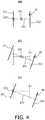
- Fig. 4schematically illustrates manipulating the caliper.
- the caliper in picture 400is schematically shown in the top view.
- the calipercomprises the first axis 221, a third axis 223, and a line segment 231.
- a mouse pointer 41is located at the second planar surface 212.
- the rotation axisis substantially identical with the first caliper axis 221.
- the first caliper axis 221is automatically aligned with an axis of an anatomical or pathological structure, e.g., a colon polyp.
- an anatomical or pathological structuree.g., a colon polyp.
- the rotation axisis substantially identical with the third caliper axis 223, which is substantially parallel to the first caliper axis 221 and crosses an end of the line segment 231.
- the usermay place the caliper so that the third axis is in a desired position in the image data space and scale and rotate the caliper to adjust its size and position.
- the userplaces the mouse pointer over the second planar surface 212, presses a mouse button, and moves the mouse, thereby dragging the second planar surface 212, the caliper is scaled and/or rotated about the rotation axis 223.
- the caliperis dropped.
- the caliper unit 330 of the system 300is arranged for visualizing the caliper in the image.
- the caliper unit 330is arranged to obtain data from the deployment unit 320 and/or the manipulation unit 325. Based on this data, the caliper unit 330 is further arranged to compute the image of the caliper in the image data space, for visualizing the caliper in the image.
- the caliper unit 330may be a component of, or may receive data from, the image unit 310 to determine how the caliper should be located and visualized in the 3D image data space.
- Fig. 5shows a top view of the caliper deployed in an image data space.
- the first axis (not visualized) of the caliperis aligned with the axis of the colon polyp 56.
- the alignmentmay be done automatically by the deployment unit 320.
- the line segment 231is displayed and the center of the line segment is marked with a cross. Further, the distance between the first and second planar surface is also displayed.
- Fig. 6shows a side view of the caliper deployed in an image data space.
- the first axis 221 of the caliperis aligned with the axis of the colon polyp 56.
- the line segment 231is displayed and the center of the line segment is marked with a cross. Further, the distance between the first and second planar surface is also displayed.
- the first and second planar surface 211 and 212, respectively,is semi-transparent. This allows the user to see the colon polyp and colon wall surface through the first and second planar surface. Further, parts of the first and second planar surface 211 and 212, respectively, which are behind the colon polyp and colon wall, are not visualized.
- This featuremay be implemented based on depth buffer values of the image pixels computed from the image data by the image unit 310 and depth buffer values of caliper pixels computed by the caliper unit 330. If a depth buffer value of an image pixel is less than a depth buffer value of a caliper pixel, the image pixel value is displayed. Otherwise, the displayed pixel value is computed based on the degree of transparency of the caliper and on the image pixel value. A curve, showing where the first and second planar surface 211 and 212, respectively, cuts through the colon polyp and colon wall surface, clearly indicates what is measured. The degree of transparency of the first and second planar surface may have different values in different parts of the first and second planar surface.
- system 300may be a valuable tool for assisting a physician in many aspects of her/his job.
- the units of the system 300may be implemented using a processor. Normally, their functions are performed under the control of a software program product. During the execution, the software program product is normally loaded into a memory, like a RAM, and executed from there. The program may be loaded from a background memory, such as a ROM, hard disk, or magnetic and/or optical storage, or may be loaded via a network like the Internet. Optionally, an application-specific integrated circuit may provide the described functionality.
- Fig. 7shows a flowchart of an exemplary implementation of the method 700 of performing and visualizing a measurement of an object viewed in an image computed from image data.
- a calipercomprising a first planar surface 211 and a second planar surface 212 substantially parallel to the first planar surface is used for performing and visualizing the measurement of the object.
- the measured size of the objectis determined based on the distance between the planes of the first and second planar surface.
- the method 700begins with an image step 710 for visualizing the image data in the image for displaying in a display. After the image step 710, the method 700 continues to a deployment step 720 for deploying the caliper in an image data space based on the location of the object in the image data space.
- the deployment step 720may be manual, semi-automated, or fully automated.
- the deployment step 720typically comprises initializing the caliper, i.e., placing the caliper in its initial position (location and orientation) in the image data space.
- the method 700continues to a caliper step 730 for visualizing the caliper in the image.
- the method 700may continue to an optional manipulation step 725 for manipulating the caliper in the image data space, or terminates.
- the optional manipulation stepmay comprise a scaling step 725-1 for scaling the caliper in the image data space, a translation step 725-2 for manipulating the caliper in the image data space, and/or a rotation step 725-3 for rotating the caliper in the image data space.
- the method 700returns to the caliper step 730.
- steps of the method 700 of the current inventionmay be combined into one step.
- a step of the method 700 of the current inventionmay be split into a plurality of steps.
- Fig. 8schematically shows an exemplary embodiment of the image acquisition apparatus 800 employing the system 300, said image acquisition apparatus 800 comprising a CT image acquisition unit 810 connected via an internal connection with the system 300, an input connector 801, and an output connector 802.
- This arrangementadvantageously increases the capabilities of the image acquisition apparatus 800, providing said image acquisition apparatus 800 with advantageous capabilities of the system 300.
- Fig. 9schematically shows an exemplary embodiment of the workstation 900.
- the workstationcomprises a user interface bus 901.
- a processor 910, a memory 920, a disk input/output (I/O) adapter 930, and a user interface (UI) 940are operatively connected to the user interface bus 901.
- a disk storage device 931is operatively coupled to the disk I/O adapter 930.
- a keyboard 941, a mouse 942, and a display 943are operatively coupled to the UI 940.
- the system 300 of the invention, implemented as a computer program,is stored in the disk storage device 931.
- the workstation 900is arranged to load the program and input data into memory 920 and execute the program on the processor 910.
- the usercan input information to the workstation 900, using the keyboard 941 and/or the mouse 942.
- the workstationis arranged to output information to the display device 943 and/or to the disk 931.
- the skilled personwill understand that there are numerous other embodiments of the workstation 900 known in the art and that the present embodiment serves the purpose of illustrating the invention and must not be interpreted as limiting the invention to this particular embodiment.
Landscapes
- Engineering & Computer Science (AREA)
- Health & Medical Sciences (AREA)
- Physics & Mathematics (AREA)
- Life Sciences & Earth Sciences (AREA)
- General Physics & Mathematics (AREA)
- Theoretical Computer Science (AREA)
- General Health & Medical Sciences (AREA)
- Medical Informatics (AREA)
- Computer Vision & Pattern Recognition (AREA)
- Biophysics (AREA)
- Surgery (AREA)
- Dentistry (AREA)
- Oral & Maxillofacial Surgery (AREA)
- General Engineering & Computer Science (AREA)
- Computer Hardware Design (AREA)
- Pathology (AREA)
- Biomedical Technology (AREA)
- Heart & Thoracic Surgery (AREA)
- Computer Graphics (AREA)
- Molecular Biology (AREA)
- Software Systems (AREA)
- Animal Behavior & Ethology (AREA)
- Quality & Reliability (AREA)
- Public Health (AREA)
- Veterinary Medicine (AREA)
- Nuclear Medicine, Radiotherapy & Molecular Imaging (AREA)
- Radiology & Medical Imaging (AREA)
- Geometry (AREA)
- Apparatus For Radiation Diagnosis (AREA)
- Length Measuring Devices By Optical Means (AREA)
Description
- The invention relates to the field of image analysis and, more specifically, to measuring structures viewed in images.
- Computed Tomography (CT) colonoscopy, also known as virtual colonoscopy, is a technique for detecting polyps in the colon. Colon cancer is often preceded by the presence of a benign polyp before it becomes malignant. The size of a polyp is important because it helps predict the likelihood of malignancy. The measured size of a polyp in CT colonography images is used to determine the action a patient has to undergo after examination.
- Currently, the polyp size on two-dimensional (2D) or three-dimensional (3D) colonography images may be measured manually by measuring the distance between two points placed at two locations on the polyp base visualized in an image. The CT colonography software computes the Euclidean distance between the two points. When using a 2D image to perform the measurement, e.g., on an axial or multiplanar reformatted image, each point is placed on the colon wall somewhere halfway between the black (the colon air) and the white (the colon wall) gray value. In 3D, the points are positioned directly on the visible colon surface. The polyp size is determined on the basis of the distance of the two points. A manual measurement technique for measuring the polyp size is described byP. J. Pickhardt et al. in an article entitled "Linear polyp measurement at CT colonography: In vitro and in vivo comparison of two-dimensional and three-dimensional displays", published Radiology, vol. 236 (2005), no. 3, pages 872-878. In automatic measurements, the size of the polyp is computed based on image data segmentation results. An automatic measurement technique for measuring the polyp size is described byD. Burling et al. in an article entitled "Ct colonography: Automatic measurement of polyp diameter compared with manual assessment - an in-vivo study", published in Clinical Radiology 62 (2007), pages 145-151.
- The polyp size is visualized by a line segment defined by the two points in a manual approach or floating inside the colon wall or in the air above the polyp in an automatic approach. This way of visualizing the measured polyp size does not always show the relationship between the measurement and the measured object.
- Further, in a manual approach, the measured size of the object may be less accurate.
Fig. 1A schematically illustrates a manually measured polyp size according to prior art. In atop view 11, twopoints contour 100 which is assumed to represent a projection of the polyp on a plane perpendicular to the viewing direction. The distance D1 between the selected twopoints side view 12 of the polyp one can see that the distance D1 does not coincide with the size of thecontour 100. - Document
WO 2005/022464 A1 discloses a method for developing an executable template of an image processing protocol. The method includes placement of anatomical marks in a reference image and combining or joining the marks to define one or more geometric objects in the image. The protocol can include the placement of labels specifying lengths or distances between marks or the defined geometrical objects. - The document YESHWANT S.C et al: "Polyps: Linear and volumetric measurements at CT colonography", RADIOLOGY, Radiological Society of North America, vol. 241, no. 3, December 2006 (2006-12), pages 802-811, discusses a study analyzing computed tomography based methods for measurement of polyps. Use of a built-in software-based caliper tool is disclosed for making multiple diameter measurements of each of a number of polyps.
- The documentPREIM et al.: "Integration of measurement tools in medical 3d visualizations", Proceedings of 2012 IEEE annual conference on visualization, 27/10 to 01/11 2002, pages 21-28, discloses the integration of several measurement tools. The document discloses interactive 3D measurements, including 3D point-to-point distance line widget and thin cylindrical interactive rulers. The document discloses as well a 3D interactive tool for volume approximation, wherein simple geometric shapes are used for volume approximation, comprising cuboids, ellipsoids and cylinders. In this volume approximation method, a selected shape is interactively placed and oriented in 3D by the user, so as to completely enclose a lesion. The document firther discloses a tool for automatic measurement of the 3D extent of a pre-segmented lesion, the respective lengths of the principal directions being obtained by principal component analysis (PCA) of the segmented region.
- The invention is defined by the claims.
- The embodiments and/or examples of the following description which are not covered by the appended claims are to be considered as not being part of the present invention.
- It would be advantageous to have a system that improves visualizing a size measurement of an anatomical or pathological structure.
- To better address this issue, in an aspect of the invention, a system for performing and visualizing a size measurement of an object viewed in an image computed from image data is provided, the system comprising:
- an image unit for visualizing the image data in the image for displaying in a display, where said deploying comprises placing the caliper in a location in the image data space;
- a deployment unit for deploying a caliper in an image data space based on the location of the object in the image data space;
a caliper unit for visualizing the caliper in the image;
a manipulation unit for manipulating the caliper in the image data space based on a user input, wherein the manipulation unit is arranged to rotate the caliper in three-dimensional image data space about a selected rotation axis based on the user input;
wherein the caliper comprises a first planar surface and a second planar surface, substantially parallel to the first planar surface, and wherein the measurement of the object is determined based on the distance between the planes of the first and second planar surface, wherein the distance between the planes of the first and second planar surface is determined as the measured size of the object. - Viewing the first and second planar surfaces of the caliper, visualized together with the measured object, improves the visualization of the size measurement of an anatomical or pathological structure, because the first and second planar surface help a user to relate the size measurement to the object.
- The manipulations of the caliper may comprise translations, rotations and scaling of the caliper. Scaling of the caliper may be isotropic or directional. The manipulations allow to better position the caliper relative to the object and may thus improve performing the size measurement, because it is easier to see what is being measured. Advantageously, the size of the object measured by the system of the invention is often more accurate.
Fig. 1B schematically illustrates a manually measured polyp size according to the invention. In atop view 11, the first andsecond surface 211 of the caliper and 212, respectively, is adjacent to acontour 100 which is assumed to represent a projection of the polyp on a plane perpendicular to the viewing direction. The distance D2 between the twosurfaces side view 12 further illustrates the distance D2 measured by the caliper of the invention. - In an embodiment of the system, the first or second planar surface is semi-transparent. Semi-transparent planar surfaces allow viewing the object and other anatomical structures displayed in an image computed from the image data by the image unit through the first and second planar surface.
- In an embodiment of the system, the caliper further comprises a caliper axis. The caliper axis may be a rotation axis of the caliper. The caliper axis may further improve aligning the caliper with the measured object, in particular with an object having its own axis.
- In an embodiment of the system, the deployment unit is further arranged for aligning the caliper axis with an axis of the object. This makes aligning the caliper with an axis of the object, e.g., with a colon polyp axis, easier for the user of the system.
- In an embodiment, the system is used for measuring a colon polyp in a colonoscopic CT image. Advantageously, the system has proved very useful in test measurements of colon polyps in colonoscopic CT images.
- In a further aspect of the invention, the system according to the invention is comprised in an image acquisition apparatus.
- In a further aspect of the invention, the system according to the invention is comprised in a workstation.
- In a further aspect of the invention, a method of performing and visualizing a size measurement of an object viewed in an image computed from image data is provided, the method comprising:
- an image step for visualizing the image data in the image for displaying in a display;
- a deployment step for deploying a caliper in an image data space based on the location of the object in the images data space, where said deploying comprises placing the caliper in a location in the image data space;
- a caliper step for visualizing the caliper in the image; and
a manipulation step for manipulating the caliper in the image data space based on a user input, wherein the manipulation step rotates the caliper in three-dimensional image data space about a selected rotation axis based on the user input;
wherein the caliper comprises a first planar surface and a second planar surface, substantially parallel to the first planar surface, and wherein the size measurement of the object is determined based on the distance between the planes of the first and second planar surface, wherein the distance between the planes of the first and second planar surface is determined as the measured size of the object. - In a further aspect of the invention, a computer program product to be loaded by a computer arrangement is provided, the computer program product comprising instructions for performing and visualizing a size measurement of an object viewed in an image computed from image data, the computer arrangement comprising a processing unit and a memory, the computer program product, after being loaded, providing said processing unit with the capability to carry out the following tasks:
- visualizing the image data in the image for displaying in a display;
- deploying a caliper in an image data space based on the location of the object in the images data space, where said deploying comprises placing the caliper in a location in the image data space;
- visualizing the caliper in the image; and
manipulating the caliper in the image data space based on a user input, wherein the manipulating rotates the caliper in three-dimensional image data space about a selected rotation axis based on the user input;
wherein the caliper comprises a first planar surface and a second planar surface, substantially parallel to the first planar surface, and wherein the size measurement of the object is determined based on the distance between the planes of the first and second planar surface, wherein the distance between the planes of the first and second planar surface is determined as the measured size of the object. - It will be appreciated by those skilled in the art that two or more of the above-mentioned embodiments, implementations, and/or aspects of the invention may be combined in any way deemed useful.
- Modifications and variations of the image acquisition apparatus, of the workstation, of the method, and/or of the computer program product, which correspond to the described modifications and variations of the system, can be carried out by a skilled person on the basis of the present description.
- The skilled person will appreciate that the system may be applied to view reports comprising multidimensional image data, e.g., 2-dimensional, 3-dimensional, or 4-dimensional images, acquired by various acquisition modalities such as, but not limited to, standard X-ray Imaging, Computed Tomography (CT), Magnetic Resonance Imaging (MRI), Ultrasound (US), Positron Emission Tomography (PET), Single Photon Emission Computed Tomography (SPECT), Digital Tomosynthesis, and Nuclear Medicine (NM).
- These and other aspects of the invention will become apparent from and will be elucidated with respect to the implementations and embodiments described hereinafter and with reference to the accompanying drawings, wherein:
Fig. 1A schematically illustrates a manually measured polyp size according to prior art;Fig. 1B schematically illustrates a manually measured polyp size according to the invention;Fig. 2 illustrates exemplary embodiments of the caliper of the invention;Fig. 3 schematically shows a block diagram of an exemplary embodiment of the system;Fig. 4 schematically illustrates manipulating the caliper;Fig. 5 shows a top view of the caliper deployed in an image data space;Fig. 6 shows a side view of the caliper deployed in an image data space;Fig. 7 shows a flowchart of an exemplary implementation of the method;Fig. 8 schematically shows an exemplary embodiment of the image acquisition apparatus; andFig. 9 schematically shows an exemplary embodiment of the workstation.- Identical reference numerals are used to denote similar parts throughout the Figures.
Fig. 2 illustrates exemplary embodiments of the caliper of the invention. Afirst embodiment 21 of the caliper comprises a firstplanar surface 211 and a second planar surface, substantially parallel to the firstplanar surface 212. The first and second planar surface are both a rectangle. The rectangles are aligned with each other, i.e., the line determined by a pair of corresponding vertices of the first and second planar surface is substantially perpendicular to the first and second planar surface. The skilled person will understand that other shapes and/or alignments are also possible and that the scope of the invention is not limited by the shape and alignment of the first and second planar surface used to illustrate the invention. For example, in an embodiment, the first and second planar surface may be a triangle or a circle. In an embodiment, a circle of the first planar surface may have a radius different from, or may be not coaxial with, a circle of the second planar surface. A size of the object is determined based on the distance between the planes of the first and second planar surface.- A
second embodiment 22 of the caliper comprises afirst caliper axis 221 and asecond caliper axis 222. Thefirst caliper axis 221 is substantially parallel to the first and second planar surface and placed substantially in the middle between the two planar surfaces. Thesecond caliper axis 222 is defined by the centers of the first and second planar surface. The first and/orsecond caliper axis 221 and/or 222, respectively, may or may not be visualized in an image. The first andsecond caliper axis 221 and/or 222, respectively, may be helpful in aligning the caliper with an anatomical or pathological structure such as a colon polyp. - A
third embodiment 23 of the caliper comprises aline segment 231. The ends of theline segment 231 are the centers of the top sides of the rectangles of the first and secondplanar surface line segment 231 is perpendicular to the first and second planar surface and may be useful for visualizing the size of the measured object. - A
fourth embodiment 24 of the caliper comprises a thirdrectangular surface 241 substantially perpendicular to the first and second planar surface. The vertices of this rectangle are the centers of the top and bottom side of the rectangles of the first and second planar surface. - The skilled person will appreciate that other structural or functional elements may be added to the described embodiments of the caliper. These elements may further improve performance and/or visualization of the caliper.
Fig. 3 schematically shows a block diagram of an exemplary embodiment of thesystem 300 for performing and visualizing a measurement of an object viewed in an image computed from image data, the system comprising:- an
image unit 310 for visualizing the image data in the image for displaying in a display; - a
deployment unit 320 for deploying a caliper in an image data space based on the location of the object in the images data space; and - a
caliper unit 330 for visualizing the caliper in the image; - The exemplary embodiment of the
system 300 further comprises the following units: - a
manipulation unit 325 for manipulating the caliper in the image data space; and - a
memory unit 370 for storing data. - In an embodiment of the
system 300, there are threeinput connectors first input connector 381 is arranged to receive data coming in from a data storage means such as, but not limited to, a hard disk, a magnetic tape, a flash memory, or an optical disk. Thesecond input connector 382 is arranged to receive data coming in from a user input device such as, but not limited to, a mouse or a touch screen. Thethird input connector 383 is arranged to receive data coming in from a user input device such as a keyboard. Theinput connectors input control unit 380. - In an embodiment of the
system 300, there are twooutput connectors first output connector 391 is arranged to output the data to a data storage means such as a hard disk, a magnetic tape, a flash memory, or an optical disk. Thesecond output connector 392 is arranged to output the data to a display device. Theoutput connectors output control unit 390. - The skilled person will understand that there are many ways to connect input devices to the
input connectors output connectors system 300. These ways comprise, but are not limited to, a wired and a wireless connection, a digital network such as, but not limited to, a Local Area Network (LAN) and a Wide Area Network (WAN), the Internet, a digital telephone network, and an analog telephone network. - In an embodiment of the
system 300, thesystem 300 comprises amemory unit 370. Thesystem 300 is arranged to receive input data from external devices via any of theinput connectors memory unit 370. Loading the input data into thememory unit 370 allows quick access to relevant data portions by the units of thesystem 300. The input data may comprise, for example, the image data. Thememory unit 370 may be implemented by devices such as, but not limited to, a Random Access Memory (RAM) chip, a Read Only Memory (ROM) chip, and/or a hard disk drive and a hard disk. Thememory unit 370 may be further arranged to store the output data. The output data may comprise, for example, data for displaying the caliper. Thememory unit 370 may be also arranged to receive data from and deliver data to the units of thesystem 300 comprising theimage unit 310, thedeployment unit 320, themanipulation unit 325, and thecaliper unit 330, via amemory bus 375. Thememory unit 370 is further arranged to make the output data available to external devices via any of theoutput connectors system 300 in thememory unit 370 may advantageously improve performance of the units of thesystem 300 as well as the rate of transfer of the output data from the units of thesystem 300 to external devices. - Alternatively, the
system 300 may comprise nomemory unit 370 and nomemory bus 375. The input data used by thesystem 300 may be supplied by at least one external device, such as an external memory or a processor, connected to the units of thesystem 300. Similarly, the output data produced by thesystem 300 may be supplied to at least one external device, such as an external memory or a processor, connected to the units of thesystem 300. The units of thesystem 300 may be arranged to receive the data from each other via internal connections or via a data bus. - The
image unit 310 of thesystem 300 is arranged for visualizing the image data in the image for displaying on a display. The tasks to be performed by theimage unit 310 include, for example, determining a viewport for displaying the image. The skilled person will know typical functions, which can be implemented in embodiments of theimage unit 310. - There are many ways of computing a view of a 3D region of image data space. The view may be computed using, for example, maximum intensity projection (MIP), iso-surface projection (ISP), and direct volume rendering (DVR). In MIP, a 3D location of maximum intensity along a projection ray is found. The ray is cast from a viewing plane. The intensity value of the pixel on the viewing plane may be set to the found maximum intensity value along the ray. In ISP, projection rays are terminated when they cross the iso-surface of interest. The iso-surface is defined as the level set of the intensity function, i.e. the set of all voxels having the same intensity value. More information on MIP and ISP can be found in a book byBarthold Lichtenbelt, Randy Crane, and Shaz Naqvi, entitled "Introduction to Volume Rendering", published by Hewlett-Packard Professional Books, Prentice Hall; Bk&CD-Rom edition (1998). In DVR, a transfer function assigns a renderable property, such as opacity, to intensity values comprised in the image data. An implementation of DVR is described in an article byT. He et al, entitled "Generation of Transfer Functions with Stochastic Search Techniques" in Proceedings of IEEE Visualization, pages 227- 234, 1996.
- Objects such as iso-surfaces may be identified in the image data and may be used to define objects in model coordinate systems of a graphics processor. A graphics pipeline of the graphics processor may be used to compute the view of the objects comprised in the model coordinate systems. The graphics pipeline is described in a book byJ. D. Foley et al, entitled "Computer graphics: Principles and practice", 2nd Ed., Addison-Wesley, Reading, Massachusetts, USA, 1996.
- The skilled person will understand that there are many methods that may be employed for computing a view of a 3D region of image data space. The choice of the method of computing the view of the 3D region of the image data space does not limit the scope of the claims.
- The
deployment unit 320 of the system is arranged for deploying a caliper in an image data space. In an embodiment of thesystem 300, the caliper is deployed in a predefined location of the image data space or in a location specified by the user. Optionally, thedeployment unit 320 may be arranged to receive a user input for specifying a caliper of a plurality of calipers for deployment. - In an embodiment of the
system 300, thedeployment unit 320 is arranged for segmenting the image data and deploying the caliper based on the image data segmentation. A method of segmenting, for example, a colon polyp is described byJ. J. Dijkers et al. in an article entitled "Segmentation and size measurement of polyps in ct colonography, published in"Medical image computing and computer-assisted intervention - MICCAI 2005, pt. 1, vol. 3749, 2005, pp. 712-719, hereinafter referred to as Ref. 1. The size of the polyp can be also computed using the method described in Ref. 1. Optionally, there may be a separate segmentation unit for segmenting the image data, comprised in thesystem 300. - In an embodiment of the
system 300, thedeployment unit 320 is arranged to determine the colon polyp axis based on the segmentation results and to align an axis of the caliper with the determined colon polyp axis. Ref. 1 describes how to determine the colon polyp axis. The colon polyp axis may be defined by two points, the polyp mean point and the polyp center point. The polyp mean point is computed by taking the mean of all points obtained in the polyp segmentation; the polyp center point is derived by minimizing the sum of distances of a point to all the surface normals. - In an embodiment of the
system 300, thedeployment unit 320 is further arranged to compute the size of the polyp and rotate and scale the aligned caliper based on the image data segmentation, using the method described in Ref. 1, for example. - The
optional manipulation unit 325 is needed when measuring the size of the organ is performed manually. In an embodiment of thesystem 300, after the caliper has been deployed, themanipulation unit 325 is arranged to receive a user input from a user input device, such as a mouse, a trackball, or a keyboard, for example. The manipulation unit may be further arranged to translate, rotate, and/or scale the caliper based on the user input. - In an embodiment of the
system 300, themanipulation unit 325 is arranged for translating the caliper in the image data space. Themanipulation unit 325 is arranged to compute the translated location of the caliper on the basis of the user input. In an embodiment, the translation vectors are substantially parallel to the viewing plane. In another embodiment, the user may be also able to zoom in and out the caliper, when a perspective projection technique is used to compute the view of the region of the image data space. - In an embodiment of the
system 300, themanipulation unit 325 is arranged for rotating the caliper in the image data space. Any number of rotation axes may be implemented. A rotation axis may be one of the three Cartesian axes of a reference system in the image data space. Alternatively, a rotation axis may be an axis of the caliper. For each rotation, a rotation axis and/or angle are selected by the user, and user input data specifying the rotation axis and/or angle is obtained by themanipulation unit 325. - In an embodiment of the
system 300, themanipulation unit 325 is arranged for scaling the caliper by a scaling factor in a direction in the image data space. Scaling of the caliper may be isotropic or anisotropic. For example, scaling of the caliper may be defined in a direction substantially perpendicular to the first and second planar surface. In this case, the scaling factor determines the distance between the first and second planar surface. In the case of isotropic scaling of the caliper, both the distance between the two planar surfaces and the size of the first and second planar surface are scaled. In this case too, the scaling factor determines the distance between the first and second planar surface. Scaling of a 3D caliper may occur in a plurality of directions. Optionally, a plurality of scaling factors may be determined, e.g., one scaling factor for each scaling direction. Optionally, the mode of scaling may be selectable and may be determined by the user. Fig. 4 schematically illustrates manipulating the caliper. The caliper inpicture 400 is schematically shown in the top view. The caliper comprises thefirst axis 221, athird axis 223, and aline segment 231. Amouse pointer 41 is located at the secondplanar surface 212.- In a first implementation or mode of operation, illustrated in
picture 401, the rotation axis is substantially identical with thefirst caliper axis 221. Thefirst caliper axis 221 is automatically aligned with an axis of an anatomical or pathological structure, e.g., a colon polyp. Thus, only rotations and scaling are needed for manipulating the caliper. When the user places the mouse pointer over the firstplanar surface 211 or secondplanar surface 212, presses a mouse button, and moves themouse 41, thereby dragging the selected first or second planar surface, the caliper is scaled and/or rotated about therotation axis 221. When the user releases the mouse button, the caliper is dropped. - In a second implementation or mode of operation, illustrated in
picture 402, the rotation axis is substantially identical with thethird caliper axis 223, which is substantially parallel to thefirst caliper axis 221 and crosses an end of theline segment 231. The user may place the caliper so that the third axis is in a desired position in the image data space and scale and rotate the caliper to adjust its size and position. When the user places the mouse pointer over the secondplanar surface 212, presses a mouse button, and moves the mouse, thereby dragging the secondplanar surface 212, the caliper is scaled and/or rotated about therotation axis 223. When the user releases the mouse button, the caliper is dropped. - Those skilled in the art will know other ways of implementing the deployment, segmentation, and/or manipulation of the caliper. The described implementations illustrate the invention and should not be construed as limiting the scope of the claims.
- The
caliper unit 330 of thesystem 300 is arranged for visualizing the caliper in the image. Thecaliper unit 330 is arranged to obtain data from thedeployment unit 320 and/or themanipulation unit 325. Based on this data, thecaliper unit 330 is further arranged to compute the image of the caliper in the image data space, for visualizing the caliper in the image. Thecaliper unit 330 may be a component of, or may receive data from, theimage unit 310 to determine how the caliper should be located and visualized in the 3D image data space. Fig. 5 shows a top view of the caliper deployed in an image data space. The first axis (not visualized) of the caliper is aligned with the axis of thecolon polyp 56. The alignment may be done automatically by thedeployment unit 320. Theline segment 231 is displayed and the center of the line segment is marked with a cross. Further, the distance between the first and second planar surface is also displayed.Fig. 6 shows a side view of the caliper deployed in an image data space. Here too, thefirst axis 221 of the caliper is aligned with the axis of thecolon polyp 56. Theline segment 231 is displayed and the center of the line segment is marked with a cross. Further, the distance between the first and second planar surface is also displayed. The first and secondplanar surface planar surface image unit 310 and depth buffer values of caliper pixels computed by thecaliper unit 330. If a depth buffer value of an image pixel is less than a depth buffer value of a caliper pixel, the image pixel value is displayed. Otherwise, the displayed pixel value is computed based on the degree of transparency of the caliper and on the image pixel value. A curve, showing where the first and secondplanar surface - Although the embodiments of the
system 300 are illustrated with applications of thesystem 300 for performing or visualizing measurements of the colon polyp, the skilled person will understand that other applications of thesystem 300, e.g., to perform or visualize measurements of the diameter of a blood vessel or the size of a lung nodule, may also be useful. The described applications illustrate the invention and should not be interpreted as limiting the invention. - The skilled person will understand that other embodiments of the
system 300 are also possible. It is possible, among other things, to redefine the units of thesystem 300 and to redistribute their functions. Although the described embodiments apply to medical images, other applications of thesystem 300, outside the medical domain, are also possible. - The skilled person will further recognize that the
system 300 may be a valuable tool for assisting a physician in many aspects of her/his job. - The units of the
system 300 may be implemented using a processor. Normally, their functions are performed under the control of a software program product. During the execution, the software program product is normally loaded into a memory, like a RAM, and executed from there. The program may be loaded from a background memory, such as a ROM, hard disk, or magnetic and/or optical storage, or may be loaded via a network like the Internet. Optionally, an application-specific integrated circuit may provide the described functionality. Fig. 7 shows a flowchart of an exemplary implementation of themethod 700 of performing and visualizing a measurement of an object viewed in an image computed from image data. A caliper comprising a firstplanar surface 211 and a secondplanar surface 212 substantially parallel to the first planar surface is used for performing and visualizing the measurement of the object. The measured size of the object is determined based on the distance between the planes of the first and second planar surface. Themethod 700 begins with animage step 710 for visualizing the image data in the image for displaying in a display. After theimage step 710, themethod 700 continues to adeployment step 720 for deploying the caliper in an image data space based on the location of the object in the image data space. Thedeployment step 720 may be manual, semi-automated, or fully automated. Thedeployment step 720 typically comprises initializing the caliper, i.e., placing the caliper in its initial position (location and orientation) in the image data space. After thedeployment step 720, themethod 700 continues to acaliper step 730 for visualizing the caliper in the image. After thecaliper step 730, themethod 700 may continue to anoptional manipulation step 725 for manipulating the caliper in the image data space, or terminates. The optional manipulation step may comprise a scaling step 725-1 for scaling the caliper in the image data space, a translation step 725-2 for manipulating the caliper in the image data space, and/or a rotation step 725-3 for rotating the caliper in the image data space. After themanipulation step 725, themethod 700 returns to thecaliper step 730.- The skilled person may change the order of some steps or perform some steps concurrently using threading models, multi-processor systems or multiple processes without departing from the concept as intended by the present invention. Optionally, two or more steps of the
method 700 of the current invention may be combined into one step. Optionally, a step of themethod 700 of the current invention may be split into a plurality of steps. Fig. 8 schematically shows an exemplary embodiment of theimage acquisition apparatus 800 employing thesystem 300, saidimage acquisition apparatus 800 comprising a CTimage acquisition unit 810 connected via an internal connection with thesystem 300, aninput connector 801, and anoutput connector 802. This arrangement advantageously increases the capabilities of theimage acquisition apparatus 800, providing saidimage acquisition apparatus 800 with advantageous capabilities of thesystem 300.Fig. 9 schematically shows an exemplary embodiment of theworkstation 900. The workstation comprises auser interface bus 901. Aprocessor 910, amemory 920, a disk input/output (I/O)adapter 930, and a user interface (UI) 940 are operatively connected to theuser interface bus 901. Adisk storage device 931 is operatively coupled to the disk I/O adapter 930. Akeyboard 941, amouse 942, and adisplay 943 are operatively coupled to theUI 940. Thesystem 300 of the invention, implemented as a computer program, is stored in thedisk storage device 931. Theworkstation 900 is arranged to load the program and input data intomemory 920 and execute the program on theprocessor 910. The user can input information to theworkstation 900, using thekeyboard 941 and/or themouse 942. The workstation is arranged to output information to thedisplay device 943 and/or to thedisk 931. The skilled person will understand that there are numerous other embodiments of theworkstation 900 known in the art and that the present embodiment serves the purpose of illustrating the invention and must not be interpreted as limiting the invention to this particular embodiment.- It should be noted that the above-mentioned embodiments illustrate rather than limit the invention and that those skilled in the art will be able to design alternative embodiments without departing from the scope of the appended claims. In the claims, any reference signs placed between parentheses shall not be construed as limiting the claim. The word "comprising" does not exclude the presence of elements or steps not listed in a claim or in the description. The word "a" or "an" preceding an element does not exclude the presence of a plurality of such elements. The invention can be implemented by means of hardware comprising several distinct elements and by means of a programmed computer. In the system claims enumerating several units, several of these units can be embodied by one and the same item of hardware or software. The usage of the words first, second and third, etc., does not indicate any ordering. These words are to be interpreted as names.
Claims (9)
- A system (300) for performing and visualizing a size measurement of an object viewed in an image computed from image data, the system comprising:- an image unit (310) for visualizing the image data in the image for displaying in a display;- a deployment unit (320) for deploying a caliper (21; 22; 23; 24) in an image data space based on the location of the object in the image data space, where said deploying comprises placing the caliper in a location in the image data space;- a caliper unit (330) for visualizing the caliper (21; 22; 23; 24) in the image; and
a manipulation unit for manipulating the caliper (21; 22; 23; 24) in the image data space based on a user input, wherein the manipulation unit is arranged to rotate the caliper in three-dimensional image data space about a selected rotation axis based on the user input;
wherein the caliper (21; 22; 23; 24) comprises a first planar surface (211) and a second planar surface (212) substantially parallel to the first planar surface (211), and wherein the size measurement of the object is determined based on the distance between the planes of the first and second planar surface, wherein the distance between the planes of the first and second planar surface is determined as the measured size of the object. - A system as claimed in claim 1, wherein the first or second planar surface is semi-transparent.
- A system as claimed in claim 1, wherein the caliper further comprises a caliper axis (221; 222; 223).
- A system as claimed in claim 3, wherein the deployment unit is further arranged for aligning the caliper axis (221; 222; 223) with an axis of the object.
- A system as claimed in claim 1, for measuring a colon polyp (56) in a colonoscopic CT image.
- An image acquisition apparatus (800) comprising a system (300) as claimed in claim 1.
- A workstation (900) comprising a system (300) as claimed in claim 1.
- A computer-implemented method (700) of performing and visualizing a size measurement of an object viewed in an image computed from image data, the method comprising:- an image step (710) for visualizing the image data in the image for displaying in a display;- a deployment step (720) for deploying a caliper (21; 22; 23; 24) in an image data space based on the location of the object in the image data space, where said deploying comprises placing the caliper in a location in the image data space;- a caliper step (730) for visualizing the caliper (21; 22; 23; 24) in the image; and
a manipulation step for manipulating the caliper (21; 22; 23; 24) in the image data space based on a user input, wherein the manipulation step rotates the caliper in three-dimensional image data space about a selected rotation axis based on the user input;
wherein the caliper (21; 22; 23; 24) comprises a first planar surface (211) and a second planar surface (212) substantially parallel to the first planar surface (211), and wherein the size measurement of the object is determined based on the distance between the planes of the first and second planar surface, wherein the distance between the planes of the first and second planar surface is determined as the measured size of the object. - A computer program product to be loaded by a computer arrangement, comprising instructions for performing and visualizing a size measurement of an object viewed in an image computed from image data, the computer arrangement comprising a processing unit and a memory, the computer program product, after being loaded, providing said processing unit with the capability to carry out the tasks of:- visualizing the image data in the image for displaying in a display;- deploying a caliper (21; 22; 23; 24) in an image data space based on the location of the object in the image data space, where said deploying comprises placing the caliper in a location in the image data space;- visualizing the caliper (21; 22; 23; 24) in the image; and
manipulating the caliper in the image data space based on a user input, wherein the manipulating rotates the caliper in three-dimensional image data space about a selected rotation axis based on the user input;
wherein the caliper (21; 22; 23; 24) comprises a first planar surface (211) and a second planar surface (212) substantially parallel to the first planar surface (211), and wherein the size measurement of the object is determined based on the distance between the planes of the first and second planar surface, wherein the distance between the planes of the first and second planar surface is determined as the measured size of the object.
Priority Applications (1)
| Application Number | Priority Date | Filing Date | Title |
|---|---|---|---|
| EP08807583.3AEP2193500B1 (en) | 2007-09-17 | 2008-09-10 | A caliper for measuring objects in an image |
Applications Claiming Priority (3)
| Application Number | Priority Date | Filing Date | Title |
|---|---|---|---|
| EP07116529 | 2007-09-17 | ||
| PCT/IB2008/053646WO2009037616A2 (en) | 2007-09-17 | 2008-09-10 | A caliper for measuring objects in an image |
| EP08807583.3AEP2193500B1 (en) | 2007-09-17 | 2008-09-10 | A caliper for measuring objects in an image |
Publications (2)
| Publication Number | Publication Date |
|---|---|
| EP2193500A2 EP2193500A2 (en) | 2010-06-09 |
| EP2193500B1true EP2193500B1 (en) | 2019-03-27 |
Family
ID=40468519
Family Applications (1)
| Application Number | Title | Priority Date | Filing Date |
|---|---|---|---|
| EP08807583.3AActiveEP2193500B1 (en) | 2007-09-17 | 2008-09-10 | A caliper for measuring objects in an image |
Country Status (4)
| Country | Link |
|---|---|
| US (1) | US9014441B2 (en) |
| EP (1) | EP2193500B1 (en) |
| CN (1) | CN101802871B (en) |
| WO (1) | WO2009037616A2 (en) |
Families Citing this family (44)
| Publication number | Priority date | Publication date | Assignee | Title |
|---|---|---|---|---|
| WO2010049844A1 (en)* | 2008-10-29 | 2010-05-06 | Koninklijke Philips Electronics N.V. | Analyzing an at least three-dimensional medical image |
| US8908995B2 (en)* | 2009-01-12 | 2014-12-09 | Intermec Ip Corp. | Semi-automatic dimensioning with imager on a portable device |
| GB2475722B (en)* | 2009-11-30 | 2011-11-02 | Mirada Medical | Measurement system for medical images |
| JP5907780B2 (en)* | 2012-04-02 | 2016-04-26 | 富士フイルム株式会社 | Ultrasonic diagnostic equipment |
| US9779546B2 (en) | 2012-05-04 | 2017-10-03 | Intermec Ip Corp. | Volume dimensioning systems and methods |
| US10007858B2 (en) | 2012-05-15 | 2018-06-26 | Honeywell International Inc. | Terminals and methods for dimensioning objects |
| US10321127B2 (en) | 2012-08-20 | 2019-06-11 | Intermec Ip Corp. | Volume dimensioning system calibration systems and methods |
| US9939259B2 (en) | 2012-10-04 | 2018-04-10 | Hand Held Products, Inc. | Measuring object dimensions using mobile computer |
| US20140104413A1 (en) | 2012-10-16 | 2014-04-17 | Hand Held Products, Inc. | Integrated dimensioning and weighing system |
| US9080856B2 (en) | 2013-03-13 | 2015-07-14 | Intermec Ip Corp. | Systems and methods for enhancing dimensioning, for example volume dimensioning |
| US10228452B2 (en) | 2013-06-07 | 2019-03-12 | Hand Held Products, Inc. | Method of error correction for 3D imaging device |
| EP3301645B1 (en) | 2013-10-02 | 2019-05-15 | Given Imaging Ltd. | System and method for size estimation of in-vivo objects |
| US11045293B2 (en)* | 2013-10-28 | 2021-06-29 | 3Shape A/S | Method for applying design guides |
| US9823059B2 (en) | 2014-08-06 | 2017-11-21 | Hand Held Products, Inc. | Dimensioning system with guided alignment |
| US10912530B2 (en)* | 2014-09-16 | 2021-02-09 | DENTSPLY SIRONA, Inc. | Methods, systems, apparatuses, and computer programs for processing tomographic images |
| US10810715B2 (en) | 2014-10-10 | 2020-10-20 | Hand Held Products, Inc | System and method for picking validation |
| US9779276B2 (en) | 2014-10-10 | 2017-10-03 | Hand Held Products, Inc. | Depth sensor based auto-focus system for an indicia scanner |
| US10775165B2 (en) | 2014-10-10 | 2020-09-15 | Hand Held Products, Inc. | Methods for improving the accuracy of dimensioning-system measurements |
| US9897434B2 (en) | 2014-10-21 | 2018-02-20 | Hand Held Products, Inc. | Handheld dimensioning system with measurement-conformance feedback |
| US9752864B2 (en) | 2014-10-21 | 2017-09-05 | Hand Held Products, Inc. | Handheld dimensioning system with feedback |
| US10060729B2 (en) | 2014-10-21 | 2018-08-28 | Hand Held Products, Inc. | Handheld dimensioner with data-quality indication |
| US9762793B2 (en) | 2014-10-21 | 2017-09-12 | Hand Held Products, Inc. | System and method for dimensioning |
| US20160225180A1 (en)* | 2015-01-29 | 2016-08-04 | Siemens Medical Solutions Usa, Inc. | Measurement tools with plane projection in rendered ultrasound volume imaging |
| US9786101B2 (en) | 2015-05-19 | 2017-10-10 | Hand Held Products, Inc. | Evaluating image values |
| US10066982B2 (en) | 2015-06-16 | 2018-09-04 | Hand Held Products, Inc. | Calibrating a volume dimensioner |
| US20160377414A1 (en) | 2015-06-23 | 2016-12-29 | Hand Held Products, Inc. | Optical pattern projector |
| US9857167B2 (en) | 2015-06-23 | 2018-01-02 | Hand Held Products, Inc. | Dual-projector three-dimensional scanner |
| US9835486B2 (en) | 2015-07-07 | 2017-12-05 | Hand Held Products, Inc. | Mobile dimensioner apparatus for use in commerce |
| EP3118576B1 (en)* | 2015-07-15 | 2018-09-12 | Hand Held Products, Inc. | Mobile dimensioning device with dynamic accuracy compatible with nist standard |
| US20170017301A1 (en) | 2015-07-16 | 2017-01-19 | Hand Held Products, Inc. | Adjusting dimensioning results using augmented reality |
| US10094650B2 (en) | 2015-07-16 | 2018-10-09 | Hand Held Products, Inc. | Dimensioning and imaging items |
| US10249030B2 (en) | 2015-10-30 | 2019-04-02 | Hand Held Products, Inc. | Image transformation for indicia reading |
| US10225544B2 (en) | 2015-11-19 | 2019-03-05 | Hand Held Products, Inc. | High resolution dot pattern |
| US10025314B2 (en) | 2016-01-27 | 2018-07-17 | Hand Held Products, Inc. | Vehicle positioning and object avoidance |
| US10339352B2 (en) | 2016-06-03 | 2019-07-02 | Hand Held Products, Inc. | Wearable metrological apparatus |
| US9940721B2 (en) | 2016-06-10 | 2018-04-10 | Hand Held Products, Inc. | Scene change detection in a dimensioner |
| US10163216B2 (en) | 2016-06-15 | 2018-12-25 | Hand Held Products, Inc. | Automatic mode switching in a volume dimensioner |
| US10909708B2 (en) | 2016-12-09 | 2021-02-02 | Hand Held Products, Inc. | Calibrating a dimensioner using ratios of measurable parameters of optic ally-perceptible geometric elements |
| CN108498118B (en)* | 2017-02-28 | 2021-08-03 | 佳能医疗系统株式会社 | Ultrasound image diagnostic apparatus, medical image processing apparatus, and medical image processing program |
| US11047672B2 (en) | 2017-03-28 | 2021-06-29 | Hand Held Products, Inc. | System for optically dimensioning |
| JP6960521B2 (en)* | 2018-03-16 | 2021-11-05 | 富士フイルム株式会社 | Control method of acoustic wave diagnostic device and acoustic wave diagnostic device |
| US10584962B2 (en) | 2018-05-01 | 2020-03-10 | Hand Held Products, Inc | System and method for validating physical-item security |
| WO2020154904A1 (en)* | 2019-01-29 | 2020-08-06 | 深圳市科曼医疗设备有限公司 | Method for automatically measuring blood vessel diameter in ultrasound image |
| US10909677B2 (en)* | 2019-02-14 | 2021-02-02 | Clarius Mobile Health Corp. | Systems and methods for performing a measurement on an ultrasound image displayed on a touchscreen device |
Family Cites Families (20)
| Publication number | Priority date | Publication date | Assignee | Title |
|---|---|---|---|---|
| US5400513A (en) | 1993-03-10 | 1995-03-28 | Duffield; Christopher | Image size measuring device |
| US6785410B2 (en)* | 1999-08-09 | 2004-08-31 | Wake Forest University Health Sciences | Image reporting method and system |
| US7274810B2 (en)* | 2000-04-11 | 2007-09-25 | Cornell Research Foundation, Inc. | System and method for three-dimensional image rendering and analysis |
| US6944330B2 (en) | 2000-09-07 | 2005-09-13 | Siemens Corporate Research, Inc. | Interactive computer-aided diagnosis method and system for assisting diagnosis of lung nodules in digital volumetric medical images |
| US6939301B2 (en)* | 2001-03-16 | 2005-09-06 | Yaakov Abdelhak | Automatic volume measurements: an application for 3D ultrasound |
| US6829382B2 (en)* | 2001-06-13 | 2004-12-07 | Shih-Jong J. Lee | Structure-guided automatic alignment for image processing |
| US6993174B2 (en) | 2001-09-07 | 2006-01-31 | Siemens Corporate Research, Inc | Real time interactive segmentation of pulmonary nodules with control parameters |
| US8588511B2 (en)* | 2002-05-22 | 2013-11-19 | Cognex Corporation | Method and apparatus for automatic measurement of pad geometry and inspection thereof |
| US7333644B2 (en)* | 2003-03-11 | 2008-02-19 | Siemens Medical Solutions Usa, Inc. | Systems and methods for providing automatic 3D lesion segmentation and measurements |
| US20060285730A1 (en)* | 2003-08-29 | 2006-12-21 | Koninklijke Philips Electronics N.V. | Method a device and a computer program arranged to develop and execute an executable template of an image processing protocol |
| US7327857B2 (en)* | 2004-03-09 | 2008-02-05 | General Electric Company | Non-contact measurement method and apparatus |
| AU2005237517B2 (en)* | 2004-04-26 | 2011-01-20 | Claudia Ingrid Henschke | Medical imaging system for accurate measurement evaluation of changes in a target lesion |
| US20060034538A1 (en)* | 2004-07-23 | 2006-02-16 | Agfa Corporation | Method and system of automating echocardiogram measurements and reporting |
| CA2611850C (en)* | 2005-06-17 | 2014-09-30 | Orthosoft Inc. | Method and apparatus for computer-assisted femoral head resurfacing |
| US20070027408A1 (en) | 2005-07-07 | 2007-02-01 | Siemens Medical Solutions Health Services Corporation | Anatomical Feature Tracking and Monitoring System |
| US8055047B2 (en)* | 2006-08-14 | 2011-11-08 | The Board Of Trustees Of The Leland Stanford Junior University | Polyp detection using smoothed shape operators |
| CN100581479C (en)* | 2007-01-10 | 2010-01-20 | 华中科技大学 | Method for reestablishing three-D ultrasonic image |
| US7995820B2 (en)* | 2007-03-30 | 2011-08-09 | Siemens Medical Solutions Usa, Inc. | System and method for detection of fetal anatomies from ultrasound images using a constrained probabilistic boosting tree |
| WO2009037611A1 (en)* | 2007-09-17 | 2009-03-26 | Koninklijke Philips Electronics N.V. | A caliper for measuring objects in an image |
| CN102405394A (en)* | 2009-02-27 | 2012-04-04 | 体表翻译有限公司 | Estimating physical parameters using three dimensional representations |
- 2008
- 2008-09-10EPEP08807583.3Apatent/EP2193500B1/enactiveActive
- 2008-09-10CNCN2008801073568Apatent/CN101802871B/enactiveActive
- 2008-09-10WOPCT/IB2008/053646patent/WO2009037616A2/enactiveApplication Filing
- 2008-09-10USUS12/678,496patent/US9014441B2/enactiveActive
Non-Patent Citations (1)
| Title |
|---|
| None* |
Also Published As
| Publication number | Publication date |
|---|---|
| CN101802871A (en) | 2010-08-11 |
| US20100260383A1 (en) | 2010-10-14 |
| EP2193500A2 (en) | 2010-06-09 |
| WO2009037616A3 (en) | 2009-09-24 |
| WO2009037616A2 (en) | 2009-03-26 |
| US9014441B2 (en) | 2015-04-21 |
| CN101802871B (en) | 2012-09-05 |
Similar Documents
| Publication | Publication Date | Title |
|---|---|---|
| EP2193500B1 (en) | A caliper for measuring objects in an image | |
| EP2191442B1 (en) | A caliper for measuring objects in an image | |
| US7813535B2 (en) | System and method for fused PET-CT visualization for heart unfolding | |
| US8493389B2 (en) | 3D connected shadow mouse pointer | |
| US10540745B2 (en) | Zooming of medical images | |
| US7492968B2 (en) | System and method for segmenting a structure of interest using an interpolation of a separating surface in an area of attachment to a structure having similar properties | |
| US9142017B2 (en) | TNM classification using image overlays | |
| Hachaj et al. | Visualization of perfusion abnormalities with GPU-based volume rendering | |
| US9361684B2 (en) | Feature validation using orientation difference vector | |
| US20100260393A1 (en) | Navigation guide | |
| US9754411B2 (en) | Path proximity rendering | |
| US20110122134A1 (en) | Image display of a tubular structure | |
| Zhang et al. | Curvature-vector pair and its application in displaying CT colon data |
Legal Events
| Date | Code | Title | Description |
|---|---|---|---|
| PUAI | Public reference made under article 153(3) epc to a published international application that has entered the european phase | Free format text:ORIGINAL CODE: 0009012 | |
| 17P | Request for examination filed | Effective date:20100419 | |
| AK | Designated contracting states | Kind code of ref document:A2 Designated state(s):AT BE BG CH CY CZ DE DK EE ES FI FR GB GR HR HU IE IS IT LI LT LU LV MC MT NL NO PL PT RO SE SI SK TR | |
| AX | Request for extension of the european patent | Extension state:AL BA MK RS | |
| DAX | Request for extension of the european patent (deleted) | ||
| RAP1 | Party data changed (applicant data changed or rights of an application transferred) | Owner name:KONINKLIJKE PHILIPS N.V. | |
| 17Q | First examination report despatched | Effective date:20160419 | |
| REG | Reference to a national code | Ref country code:DE Ref legal event code:R079 Ref document number:602008059526 Country of ref document:DE Free format text:PREVIOUS MAIN CLASS: G06T0007600000 Ipc:G06T0019000000 | |
| GRAP | Despatch of communication of intention to grant a patent | Free format text:ORIGINAL CODE: EPIDOSNIGR1 | |
| STAA | Information on the status of an ep patent application or granted ep patent | Free format text:STATUS: GRANT OF PATENT IS INTENDED | |
| RIC1 | Information provided on ipc code assigned before grant | Ipc:G06T 19/00 20110101AFI20180920BHEP Ipc:G06T 7/62 20170101ALI20180920BHEP | |
| INTG | Intention to grant announced | Effective date:20181010 | |
| RIN1 | Information on inventor provided before grant (corrected) | Inventor name:VAN DER KRAAN, ROEL Inventor name:PETERS, JOOST, F. Inventor name:TRUYEN, ROEL | |
| GRAS | Grant fee paid | Free format text:ORIGINAL CODE: EPIDOSNIGR3 | |
| GRAA | (expected) grant | Free format text:ORIGINAL CODE: 0009210 | |
| STAA | Information on the status of an ep patent application or granted ep patent | Free format text:STATUS: THE PATENT HAS BEEN GRANTED | |
| AK | Designated contracting states | Kind code of ref document:B1 Designated state(s):AT BE BG CH CY CZ DE DK EE ES FI FR GB GR HR HU IE IS IT LI LT LU LV MC MT NL NO PL PT RO SE SI SK TR | |
| REG | Reference to a national code | Ref country code:GB Ref legal event code:FG4D | |
| REG | Reference to a national code | Ref country code:CH Ref legal event code:EP | |
| REG | Reference to a national code | Ref country code:AT Ref legal event code:REF Ref document number:1113964 Country of ref document:AT Kind code of ref document:T Effective date:20190415 | |
| REG | Reference to a national code | Ref country code:IE Ref legal event code:FG4D | |
| REG | Reference to a national code | Ref country code:DE Ref legal event code:R096 Ref document number:602008059526 Country of ref document:DE | |
| REG | Reference to a national code | Ref country code:GB Ref legal event code:746 Effective date:20190508 Ref country code:DE Ref legal event code:R084 Ref document number:602008059526 Country of ref document:DE | |
| PG25 | Lapsed in a contracting state [announced via postgrant information from national office to epo] | Ref country code:NO Free format text:LAPSE BECAUSE OF FAILURE TO SUBMIT A TRANSLATION OF THE DESCRIPTION OR TO PAY THE FEE WITHIN THE PRESCRIBED TIME-LIMIT Effective date:20190627 Ref country code:FI Free format text:LAPSE BECAUSE OF FAILURE TO SUBMIT A TRANSLATION OF THE DESCRIPTION OR TO PAY THE FEE WITHIN THE PRESCRIBED TIME-LIMIT Effective date:20190327 Ref country code:SE Free format text:LAPSE BECAUSE OF FAILURE TO SUBMIT A TRANSLATION OF THE DESCRIPTION OR TO PAY THE FEE WITHIN THE PRESCRIBED TIME-LIMIT Effective date:20190327 Ref country code:LT Free format text:LAPSE BECAUSE OF FAILURE TO SUBMIT A TRANSLATION OF THE DESCRIPTION OR TO PAY THE FEE WITHIN THE PRESCRIBED TIME-LIMIT Effective date:20190327 | |
| REG | Reference to a national code | Ref country code:NL Ref legal event code:MP Effective date:20190327 | |
| PG25 | Lapsed in a contracting state [announced via postgrant information from national office to epo] | Ref country code:NL Free format text:LAPSE BECAUSE OF FAILURE TO SUBMIT A TRANSLATION OF THE DESCRIPTION OR TO PAY THE FEE WITHIN THE PRESCRIBED TIME-LIMIT Effective date:20190327 Ref country code:GR Free format text:LAPSE BECAUSE OF FAILURE TO SUBMIT A TRANSLATION OF THE DESCRIPTION OR TO PAY THE FEE WITHIN THE PRESCRIBED TIME-LIMIT Effective date:20190628 Ref country code:BG Free format text:LAPSE BECAUSE OF FAILURE TO SUBMIT A TRANSLATION OF THE DESCRIPTION OR TO PAY THE FEE WITHIN THE PRESCRIBED TIME-LIMIT Effective date:20190627 Ref country code:HR Free format text:LAPSE BECAUSE OF FAILURE TO SUBMIT A TRANSLATION OF THE DESCRIPTION OR TO PAY THE FEE WITHIN THE PRESCRIBED TIME-LIMIT Effective date:20190327 Ref country code:LV Free format text:LAPSE BECAUSE OF FAILURE TO SUBMIT A TRANSLATION OF THE DESCRIPTION OR TO PAY THE FEE WITHIN THE PRESCRIBED TIME-LIMIT Effective date:20190327 | |
| REG | Reference to a national code | Ref country code:AT Ref legal event code:MK05 Ref document number:1113964 Country of ref document:AT Kind code of ref document:T Effective date:20190327 | |
| PG25 | Lapsed in a contracting state [announced via postgrant information from national office to epo] | Ref country code:ES Free format text:LAPSE BECAUSE OF FAILURE TO SUBMIT A TRANSLATION OF THE DESCRIPTION OR TO PAY THE FEE WITHIN THE PRESCRIBED TIME-LIMIT Effective date:20190327 Ref country code:PT Free format text:LAPSE BECAUSE OF FAILURE TO SUBMIT A TRANSLATION OF THE DESCRIPTION OR TO PAY THE FEE WITHIN THE PRESCRIBED TIME-LIMIT Effective date:20190727 Ref country code:EE Free format text:LAPSE BECAUSE OF FAILURE TO SUBMIT A TRANSLATION OF THE DESCRIPTION OR TO PAY THE FEE WITHIN THE PRESCRIBED TIME-LIMIT Effective date:20190327 Ref country code:IT Free format text:LAPSE BECAUSE OF FAILURE TO SUBMIT A TRANSLATION OF THE DESCRIPTION OR TO PAY THE FEE WITHIN THE PRESCRIBED TIME-LIMIT Effective date:20190327 Ref country code:SK Free format text:LAPSE BECAUSE OF FAILURE TO SUBMIT A TRANSLATION OF THE DESCRIPTION OR TO PAY THE FEE WITHIN THE PRESCRIBED TIME-LIMIT Effective date:20190327 Ref country code:CZ Free format text:LAPSE BECAUSE OF FAILURE TO SUBMIT A TRANSLATION OF THE DESCRIPTION OR TO PAY THE FEE WITHIN THE PRESCRIBED TIME-LIMIT Effective date:20190327 Ref country code:RO Free format text:LAPSE BECAUSE OF FAILURE TO SUBMIT A TRANSLATION OF THE DESCRIPTION OR TO PAY THE FEE WITHIN THE PRESCRIBED TIME-LIMIT Effective date:20190327 | |
| PG25 | Lapsed in a contracting state [announced via postgrant information from national office to epo] | Ref country code:PL Free format text:LAPSE BECAUSE OF FAILURE TO SUBMIT A TRANSLATION OF THE DESCRIPTION OR TO PAY THE FEE WITHIN THE PRESCRIBED TIME-LIMIT Effective date:20190327 | |
| PG25 | Lapsed in a contracting state [announced via postgrant information from national office to epo] | Ref country code:AT Free format text:LAPSE BECAUSE OF FAILURE TO SUBMIT A TRANSLATION OF THE DESCRIPTION OR TO PAY THE FEE WITHIN THE PRESCRIBED TIME-LIMIT Effective date:20190327 Ref country code:IS Free format text:LAPSE BECAUSE OF FAILURE TO SUBMIT A TRANSLATION OF THE DESCRIPTION OR TO PAY THE FEE WITHIN THE PRESCRIBED TIME-LIMIT Effective date:20190727 | |
| REG | Reference to a national code | Ref country code:DE Ref legal event code:R097 Ref document number:602008059526 Country of ref document:DE | |
| PG25 | Lapsed in a contracting state [announced via postgrant information from national office to epo] | Ref country code:DK Free format text:LAPSE BECAUSE OF FAILURE TO SUBMIT A TRANSLATION OF THE DESCRIPTION OR TO PAY THE FEE WITHIN THE PRESCRIBED TIME-LIMIT Effective date:20190327 | |
| PLBE | No opposition filed within time limit | Free format text:ORIGINAL CODE: 0009261 | |
| STAA | Information on the status of an ep patent application or granted ep patent | Free format text:STATUS: NO OPPOSITION FILED WITHIN TIME LIMIT | |
| PG25 | Lapsed in a contracting state [announced via postgrant information from national office to epo] | Ref country code:SI Free format text:LAPSE BECAUSE OF FAILURE TO SUBMIT A TRANSLATION OF THE DESCRIPTION OR TO PAY THE FEE WITHIN THE PRESCRIBED TIME-LIMIT Effective date:20190327 | |
| 26N | No opposition filed | Effective date:20200103 | |
| PG25 | Lapsed in a contracting state [announced via postgrant information from national office to epo] | Ref country code:TR Free format text:LAPSE BECAUSE OF FAILURE TO SUBMIT A TRANSLATION OF THE DESCRIPTION OR TO PAY THE FEE WITHIN THE PRESCRIBED TIME-LIMIT Effective date:20190327 | |
| PG25 | Lapsed in a contracting state [announced via postgrant information from national office to epo] | Ref country code:MC Free format text:LAPSE BECAUSE OF FAILURE TO SUBMIT A TRANSLATION OF THE DESCRIPTION OR TO PAY THE FEE WITHIN THE PRESCRIBED TIME-LIMIT Effective date:20190327 | |
| REG | Reference to a national code | Ref country code:CH Ref legal event code:PL | |
| PG25 | Lapsed in a contracting state [announced via postgrant information from national office to epo] | Ref country code:LI Free format text:LAPSE BECAUSE OF NON-PAYMENT OF DUE FEES Effective date:20190930 Ref country code:CH Free format text:LAPSE BECAUSE OF NON-PAYMENT OF DUE FEES Effective date:20190930 Ref country code:LU Free format text:LAPSE BECAUSE OF NON-PAYMENT OF DUE FEES Effective date:20190910 Ref country code:IE Free format text:LAPSE BECAUSE OF NON-PAYMENT OF DUE FEES Effective date:20190910 | |
| REG | Reference to a national code | Ref country code:BE Ref legal event code:MM Effective date:20190930 | |
| PG25 | Lapsed in a contracting state [announced via postgrant information from national office to epo] | Ref country code:BE Free format text:LAPSE BECAUSE OF NON-PAYMENT OF DUE FEES Effective date:20190930 | |
| PG25 | Lapsed in a contracting state [announced via postgrant information from national office to epo] | Ref country code:CY Free format text:LAPSE BECAUSE OF FAILURE TO SUBMIT A TRANSLATION OF THE DESCRIPTION OR TO PAY THE FEE WITHIN THE PRESCRIBED TIME-LIMIT Effective date:20190327 | |
| PG25 | Lapsed in a contracting state [announced via postgrant information from national office to epo] | Ref country code:MT Free format text:LAPSE BECAUSE OF FAILURE TO SUBMIT A TRANSLATION OF THE DESCRIPTION OR TO PAY THE FEE WITHIN THE PRESCRIBED TIME-LIMIT Effective date:20190327 Ref country code:HU Free format text:LAPSE BECAUSE OF FAILURE TO SUBMIT A TRANSLATION OF THE DESCRIPTION OR TO PAY THE FEE WITHIN THE PRESCRIBED TIME-LIMIT; INVALID AB INITIO Effective date:20080910 | |
| PGFP | Annual fee paid to national office [announced via postgrant information from national office to epo] | Ref country code:FR Payment date:20230926 Year of fee payment:16 | |
| PGFP | Annual fee paid to national office [announced via postgrant information from national office to epo] | Ref country code:DE Payment date:20240926 Year of fee payment:17 | |
| PGFP | Annual fee paid to national office [announced via postgrant information from national office to epo] | Ref country code:GB Payment date:20240924 Year of fee payment:17 | |
| PG25 | Lapsed in a contracting state [announced via postgrant information from national office to epo] | Ref country code:FR Free format text:LAPSE BECAUSE OF NON-PAYMENT OF DUE FEES Effective date:20240930 |