EP2193049B1 - Docking apparatus for portable device - Google Patents
Docking apparatus for portable deviceDownload PDFInfo
- Publication number
- EP2193049B1 EP2193049B1EP07818808AEP07818808AEP2193049B1EP 2193049 B1EP2193049 B1EP 2193049B1EP 07818808 AEP07818808 AEP 07818808AEP 07818808 AEP07818808 AEP 07818808AEP 2193049 B1EP2193049 B1EP 2193049B1
- Authority
- EP
- European Patent Office
- Prior art keywords
- base
- docking apparatus
- mounting part
- mounting
- portable device
- Prior art date
- Legal status (The legal status is an assumption and is not a legal conclusion. Google has not performed a legal analysis and makes no representation as to the accuracy of the status listed.)
- Not-in-force
Links
Images


Classifications
- B—PERFORMING OPERATIONS; TRANSPORTING
- B60—VEHICLES IN GENERAL
- B60R—VEHICLES, VEHICLE FITTINGS, OR VEHICLE PARTS, NOT OTHERWISE PROVIDED FOR
- B60R11/00—Arrangements for holding or mounting articles, not otherwise provided for
- B60R11/02—Arrangements for holding or mounting articles, not otherwise provided for for radio sets, television sets, telephones, or the like; Arrangement of controls thereof
- B60R11/0241—Arrangements for holding or mounting articles, not otherwise provided for for radio sets, television sets, telephones, or the like; Arrangement of controls thereof for telephones
- B—PERFORMING OPERATIONS; TRANSPORTING
- B60—VEHICLES IN GENERAL
- B60R—VEHICLES, VEHICLE FITTINGS, OR VEHICLE PARTS, NOT OTHERWISE PROVIDED FOR
- B60R11/00—Arrangements for holding or mounting articles, not otherwise provided for
- B60R11/02—Arrangements for holding or mounting articles, not otherwise provided for for radio sets, television sets, telephones, or the like; Arrangement of controls thereof
- G—PHYSICS
- G01—MEASURING; TESTING
- G01C—MEASURING DISTANCES, LEVELS OR BEARINGS; SURVEYING; NAVIGATION; GYROSCOPIC INSTRUMENTS; PHOTOGRAMMETRY OR VIDEOGRAMMETRY
- G01C21/00—Navigation; Navigational instruments not provided for in groups G01C1/00 - G01C19/00
- G01C21/26—Navigation; Navigational instruments not provided for in groups G01C1/00 - G01C19/00 specially adapted for navigation in a road network
- G01C21/265—Navigation; Navigational instruments not provided for in groups G01C1/00 - G01C19/00 specially adapted for navigation in a road network constructional aspects of navigation devices, e.g. housings, mountings, displays
- B—PERFORMING OPERATIONS; TRANSPORTING
- B60—VEHICLES IN GENERAL
- B60R—VEHICLES, VEHICLE FITTINGS, OR VEHICLE PARTS, NOT OTHERWISE PROVIDED FOR
- B60R11/00—Arrangements for holding or mounting articles, not otherwise provided for
- B60R11/02—Arrangements for holding or mounting articles, not otherwise provided for for radio sets, television sets, telephones, or the like; Arrangement of controls thereof
- B60R11/0229—Arrangements for holding or mounting articles, not otherwise provided for for radio sets, television sets, telephones, or the like; Arrangement of controls thereof for displays, e.g. cathodic tubes
- B60R11/0235—Arrangements for holding or mounting articles, not otherwise provided for for radio sets, television sets, telephones, or the like; Arrangement of controls thereof for displays, e.g. cathodic tubes of flat type, e.g. LCD
- B—PERFORMING OPERATIONS; TRANSPORTING
- B60—VEHICLES IN GENERAL
- B60R—VEHICLES, VEHICLE FITTINGS, OR VEHICLE PARTS, NOT OTHERWISE PROVIDED FOR
- B60R11/00—Arrangements for holding or mounting articles, not otherwise provided for
- B60R11/02—Arrangements for holding or mounting articles, not otherwise provided for for radio sets, television sets, telephones, or the like; Arrangement of controls thereof
- B60R11/0252—Arrangements for holding or mounting articles, not otherwise provided for for radio sets, television sets, telephones, or the like; Arrangement of controls thereof for personal computers, e.g. laptops, notebooks
- B—PERFORMING OPERATIONS; TRANSPORTING
- B60—VEHICLES IN GENERAL
- B60R—VEHICLES, VEHICLE FITTINGS, OR VEHICLE PARTS, NOT OTHERWISE PROVIDED FOR
- B60R11/00—Arrangements for holding or mounting articles, not otherwise provided for
- B60R11/02—Arrangements for holding or mounting articles, not otherwise provided for for radio sets, television sets, telephones, or the like; Arrangement of controls thereof
- B60R11/0258—Arrangements for holding or mounting articles, not otherwise provided for for radio sets, television sets, telephones, or the like; Arrangement of controls thereof for navigation systems
- B—PERFORMING OPERATIONS; TRANSPORTING
- B60—VEHICLES IN GENERAL
- B60R—VEHICLES, VEHICLE FITTINGS, OR VEHICLE PARTS, NOT OTHERWISE PROVIDED FOR
- B60R11/00—Arrangements for holding or mounting articles, not otherwise provided for
- B60R2011/0001—Arrangements for holding or mounting articles, not otherwise provided for characterised by position
- B60R2011/0003—Arrangements for holding or mounting articles, not otherwise provided for characterised by position inside the vehicle
- B60R2011/0005—Dashboard
- B—PERFORMING OPERATIONS; TRANSPORTING
- B60—VEHICLES IN GENERAL
- B60R—VEHICLES, VEHICLE FITTINGS, OR VEHICLE PARTS, NOT OTHERWISE PROVIDED FOR
- B60R11/00—Arrangements for holding or mounting articles, not otherwise provided for
- B60R2011/0001—Arrangements for holding or mounting articles, not otherwise provided for characterised by position
- B60R2011/0003—Arrangements for holding or mounting articles, not otherwise provided for characterised by position inside the vehicle
- B60R2011/0007—Mid-console
- B—PERFORMING OPERATIONS; TRANSPORTING
- B60—VEHICLES IN GENERAL
- B60R—VEHICLES, VEHICLE FITTINGS, OR VEHICLE PARTS, NOT OTHERWISE PROVIDED FOR
- B60R11/00—Arrangements for holding or mounting articles, not otherwise provided for
- B60R2011/0042—Arrangements for holding or mounting articles, not otherwise provided for characterised by mounting means
- B60R2011/0049—Arrangements for holding or mounting articles, not otherwise provided for characterised by mounting means for non integrated articles
- B60R2011/0064—Connection with the article
- B60R2011/0075—Connection with the article using a containment or docking space
- B—PERFORMING OPERATIONS; TRANSPORTING
- B60—VEHICLES IN GENERAL
- B60R—VEHICLES, VEHICLE FITTINGS, OR VEHICLE PARTS, NOT OTHERWISE PROVIDED FOR
- B60R11/00—Arrangements for holding or mounting articles, not otherwise provided for
- B60R2011/0042—Arrangements for holding or mounting articles, not otherwise provided for characterised by mounting means
- B60R2011/008—Adjustable or movable supports
- B60R2011/0082—Adjustable or movable supports collapsible, e.g. for storing after use
- B—PERFORMING OPERATIONS; TRANSPORTING
- B60—VEHICLES IN GENERAL
- B60R—VEHICLES, VEHICLE FITTINGS, OR VEHICLE PARTS, NOT OTHERWISE PROVIDED FOR
- B60R11/00—Arrangements for holding or mounting articles, not otherwise provided for
- B60R2011/0042—Arrangements for holding or mounting articles, not otherwise provided for characterised by mounting means
- B60R2011/008—Adjustable or movable supports
- B60R2011/0085—Adjustable or movable supports with adjustment by rotation in their operational position
- B—PERFORMING OPERATIONS; TRANSPORTING
- B60—VEHICLES IN GENERAL
- B60R—VEHICLES, VEHICLE FITTINGS, OR VEHICLE PARTS, NOT OTHERWISE PROVIDED FOR
- B60R11/00—Arrangements for holding or mounting articles, not otherwise provided for
- B60R2011/0094—Arrangements for holding or mounting articles, not otherwise provided for characterised by means for covering after user, e.g. boxes, shutters or the like
Definitions
- This inventionis concerned with a docking apparatus for a portable device, preferably a portable electric or electronic device requiring a source of power or other electric or electronic signals, and in particular, but not exclusively, a portable navigation device (PND).
- a portable navigation devicePND
- a further disadvantage with the current situationis that PNDs are currently commonly provided with cigarette lighter adapters (CLA) to provide a source of power.
- CLAcigarette lighter adapters
- the cable emanating from the CLAis unsightly, but a necessity for medium to long journeys and frequent PND usage.
- a majority of potential navigation device customerssee this as a drawback of PNDs and a reason for considering a semi- or fully-integrated navigation system.
- a primary object of this inventiontherefore is to provide a docking apparatus which:
- a docking apparatusfor a portable device, said docking apparatus comprising at least a base and a mounting part which is connected to the base, wherein the mounting part is pivotally mounted within the base and consists of at least a cover part which in a first position lies substantially flush with the base, said cover part capable of being pivoted to a second position wherein part of the cover part extends substantially upwardly from the docking apparatus, said pivotal motion also revealing a fin part attached to the underside of said cover part, and wherein at least one of
- the base and the mounting partare substantially circular in cross-section.
- At least one of the mounting part and the baseincludes push-release means which in their locked condition secure the mounting part in the first position, and in their released condition allow pivotal movement of said mounting part.
- At least one of the base and the fin part of the mounting partinclude cooperating locking means which facilitate the locking of the fin part to the base thus securing the mounting part in the second position.
- the docking apparatusincludes a base, a mounting part, and an intermediate part within which the mounting part is pivotally mounted, said intermediate part being secured to the base in a push-fit manner.
- the at least one of the mounting part and the intermediate partincludes push-release means which in their locked condition secure the mounting part in the first position, and in their released condition allow pivotal movement of said mounting part.
- at least one of the base and the fin part of the mounting partinclude cooperating locking means which facilitate the locking of the fin part to the intermediate part thus securing the mounting part in the second position.
- the mounting partis capable of both pivoting and rotating, such rotational movement being achieved either by being rotationally mounted in either the base or the intermediate part if provided, or alternatively by means of the intermediate part being rotationally mounted in the base part.
- the cooperating connection featuresare provided on the underside of the cover part of the mounting part, such allowing the portable device to be slidingly connected to said cover part when disposed in an upward condition when the mounting part is in the second position.
- the fin partis provided with at least an aperture through which either a connecting cable may pass, or by means of which an electrical connection to the portable device may be achieved.
- the fin partincludes electrical connection means, such being preferably disposed proximately the lower reaches of the cooperating connection features on the underside of the cover part such that complete sliding connection of the portable device thereto simultaneously achieves electrical connection between the portable device and said electrical connection means.
- the mounting and electrical connection of a portable deviceis achieved through an intermediate adapter component which include connection features adapted to cooperate with the connection features provided on the underside of the cover part or the fin part of the mounting part as the case may be, and additionally include at least one of
- the electrical connectionincludes facility for an antenna signal and/or audio signal to be transmitted therethrough.
- the docking apparatus of the present inventionprovides an alternative to the standard windscreen-affixed cradle mounting currently employed for portable navigation devices, and thus overcomes the various disadvantages associated therewith.
- FIG. 1Athere is shown a vehicle dashboard 2 on one side of which may be cut or provided an aperture 4 thus producing a disc 6 of dashboard material which may be trimmed and secured to an upper surface 8 of a docking apparatus indicated generally at 10.
- the docking apparatuscan substantially blend in with the dashboard once it is secured therein as hereinafter described.
- FIG. 2the underside of the docking apparatus 10 is shown, and in particular is provided with an aperture 12 through which an electrical connector 14, provided within the dashboard and wired at 16 to the internal electrical and electronic systems of the vehicle, can pass to facilitate connection thereof to a corresponding connector 18 provided within the docking apparatus.
- the docking apparatus 10comprises a base 20 consisting of an annular peripheral lip 22 from the inner edge of which depends a skirt 24 which together ensure that the base can be securely inserted in push-fit manner into the aperture 4 defined in the dashboard 2, and is prevented from falling therethrough by said lip which is supported by an upper surface 2A of the dashboard.
- the base 20is provided with deflectable tabs 26 having hook formations 28 which lock behind a lower surface 2B of said dashboard.
- an intermediate component 30is provided within the base 20 and is secured therein in push-fit manner.
- Said intermediate componentis substantially hemi-spherical in shape defining an inner cavity 32 therein to which access is had through the aperture 12.
- a mounting part indicated generally at 40which comprises a cover part 42 having an upper surface 42A to which the trimmed disc 6 is secured, and a lower surface 42B from which a fin part 44 depends.
- Said fin partmay be suitably attached to said cover part, for example by being integrally formed therewith.
- a connector 46which may be for example a commonly known "D-type" or other suitable connector, which may be simply mounted or adhered in place, or alternatively connected to a corresponding connector, possibly provided in a mounted printed circuitboard 48.
- the supply of electric power, or other electric or electronic signals to said connectoris provided through cable 47.
- An aperture 50 provided in the fin part 44exposes a further connector 52 by means of which electric/electronic connection may be achieved with the portable device.
- the mounting part 40is pivotally mounted about an axis indicated at 54, in this embodiment, in the intermediate part 30, although it should be mentioned that the intermediate component is optional, and the mounting part may be directly pivotally mounted within the base 20.
- the mounting partcan adopt two positions, a first of which is shown in Figure 3B . It is retained in this position by means of a push-cam mechanism shown in greater detail in Figure 4C .
- a push-cam mechanismshown in greater detail in Figure 4C .
- a userapplies downward pressure as indicated by arrows 58 to release the push-cam mechanism, whereupon, the cover part, fin part, and associated connectors can pivot within the intermediate component (or base) until the fin comes into substantially co-planar relationship with the lip 22 of the base 20.
- the pivoting motion and the exposure of the connectorsis clearly shown in Figures 4A , B, and the motion of a typical push-cam mechanism, known and easily implementible by one skilled in the art, is clearly shown in Figure 4C .
- connection features 62such as ribs, grooves, channels, or the like on the underside 42B of the cover part 42. It is to be mentioned that any type of connection feature may be provided, but in this embodiment, and as can more clearly be seen in Figure 5A , the connection features 62 are in the form of a pair of substantially parallel guide rails which cooperate with a pair of correspondingly shaped grooves on the rear surface of a PND or other portable device.
- the sliding lock 60is clearly accessible to a user, whereby the mounting part may be secured in the second "open" position in which a portion of the cover part 42 extends upwardly from the docking apparatus 10 at a slight angle to the vertical such that any device mounted thereon is also appropriately inclined for ease of view or use, particularly when the portable device includes a visual display.
- the position and exposure of the connector 52is to be noted, proximate the lower reaches of the connection features 62, such that sliding fitment of a portable device thereon automatically aligns the connector 52 with the corresponding connector (not shown) provided on the base of the portable device, both connectors ultimately mating when the portable device is completely and properly mounted on said cover part 42.
- the lock 60consists of a simple slider which can be moved back and forth, in one of which positions the slider engages within a suitable detent 61 provided in the intermediate component 30 to prevent further pivoting motion of the mounting part 20 and to lock said mounting part in the second, "open" position.
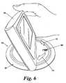
- Figure 6clearly shows a portable navigation device 70 mounted in place on the docking apparatus 10.
- An optional feature which may be incorporated into the docking apparatusis the facility for the mounting part to swivel as indicated by arrows 72, 74, further optionally while the lock is in a position which secures the cover part 42 to the intermediate component or the base as the case may be.
- an adapter 80is provided having a first connector 82 complementary to the connector 52 exposed through the aperture to the underside of fin 44 of the docking apparatus 10, and a second connector 84 which is complementary to the connector (not shown) on the underside of the portable device 70.
- connection means 86are provided to the rear of the adapter 80 which are complementary to the connection features 62 provided on the exposed surface of the cover part 42, and suitable connection features 88 are provided on the alternate face which allow for the sliding connection of the portable device 70, again included corresponding and complementary connection features (not shown) in its rear surface.
- the adaptermay either be of the type shown in Figure 7A which is sufficiently discreet to be fitted to the upstanding cover part 42 and to complete an electrical connection between the connector 82 and the connector 52 without impeding the pivotal movement of the mounting part, as shown in Figures 8A, 8B , or the adapter may be of an alternative type 90 shown in Figure 7B and 8C , which includes tabs 92, 94 allowing for push- as opposed to sliding-fit of a portable device, and a connector 96 complementary to the connector 52.
- sliding fit of adapter 90 to the cover part 42is still required for respective connection of connectors 96 and 52, as shown in Figure 7C .
- the adapteris too large to be concealed within the docking apparatus.
- the fin 44 of the mounting partis merely provided with an aperture 50 through which the cable 47 may pass, the connector 46 at the end thereof merely being manually attached to the corresponding and complementary connector 82 of the adapter 80.
Landscapes
- Engineering & Computer Science (AREA)
- Radar, Positioning & Navigation (AREA)
- Remote Sensing (AREA)
- Mechanical Engineering (AREA)
- Automation & Control Theory (AREA)
- Physics & Mathematics (AREA)
- General Physics & Mathematics (AREA)
- Fittings On The Vehicle Exterior For Carrying Loads, And Devices For Holding Or Mounting Articles (AREA)
- Navigation (AREA)
- Connector Housings Or Holding Contact Members (AREA)
Abstract
Description
- This invention is concerned with a docking apparatus for a portable device, preferably a portable electric or electronic device requiring a source of power or other electric or electronic signals, and in particular, but not exclusively, a portable navigation device (PND).
- Docking apparatuses for electronic devices are well known. An example of such a docking apparatus is disclosed by document
US-A-2007/0171316 . The reader will be aware that docking stations for laptop computers are available and have features which cooperate in some way with corresponding and suitably designed features of the laptop itself. Specifically, the docking station will inevitably be provided with a power and/or data transfer component, typically in the form of a connector, which is received in a corresponding socket within the laptop primarily to provide a source of power thereto, and optionally to pass other electric and electronic signals, such as video signals, data, USB signals and the like to and from the laptop. Aside from this basic requirement, there are few other requirements for the docking station, except that is should support the weight of the laptop. - In the case of portable navigation devices, which are most commonly used as in-car devices, the provision of a docking station is a more complex proposition, particularly as the majority of vehicle manufacturers are highly sensitive about alterations to the appearance of the cabin, particularly any such alterations which might be obtrusive or worse, unsafe either under normal driving conditions or in an accident.
- Semi-integrated docking apparatuses for the in-car market have therefore been proposed. However, such propositions have in the past foundered on account of additional development costs required on the part of the vehicle manufacturer, and potential incompatibility issues between the electric and electronic signals commonly routed within vehicles and those required for or provided by in-car PNDs, and the connectors commonly provided on such devices and those which might be proposed by the vehicle manufacturers. Notwithstanding these difficulties, the rapid and almost global adoption of PNDs has forced vehicle manufacturers to act.
- Initial attempts by the automotive industry to adapt to the PND market have proved relatively unsuccessful, due mainly to the need for a reliable physical connection and the hugely differing development and life cycles between vehicle manufacturers and the consumer electronics industry. Additionally, there is a threat that national governments will introduce legislation that prevents the currently used PND "cradles". The current cradles are typically provided with a suction disc for attachment to the inner surface of the windscreen of the car, and a mounting part with features which cooperate with corresponding features provided on the PND unit such that the pair can be releasably connected together. Inevitably, the attachment of the these often bulky cradles to the windscreen, and the fact that such devices necessarily mount the PNDs in the cabin space of the vehicle away from the windscreen is distracting and in certain positions, can reduce driver and/or passenger visibility.
- A further consideration is one of security. PND adoption has become so widespread that thieves are now targeting vehicles in which a suction disc mark can be seen on the inner surface of the windscreen, regardless of whether the cradle remains attached to the windscreen inside the vehicle.
- A further disadvantage with the current situation is that PNDs are currently commonly provided with cigarette lighter adapters (CLA) to provide a source of power. The cable emanating from the CLA is unsightly, but a necessity for medium to long journeys and frequent PND usage. A majority of potential navigation device customers see this as a drawback of PNDs and a reason for considering a semi- or fully-integrated navigation system.
- At the time of this application, vehicle manufacturers have worked with PND suppliers to develop dashboard-embedded cradles that enable varying levels of integration.
- A primary object of this invention therefore is to provide a docking apparatus which:
- reduces the product development time of vehicle manufacturers;
- is safe, functional, and offers reliable and sound physical and electrical connection with the PND attached thereto;
- is simple and quick to operate, in terms of PND connection and disconnection, and
- is concealable after PND disconnection, in which position it provides no indication to a potential thief that a PND device is owned by the vehicle owner.
- According to the invention there is provided a docking apparatus for a portable device, said docking apparatus comprising at least a base and a mounting part which is connected to the base, wherein
the mounting part is pivotally mounted within the base and consists of at least a cover part which in a first position lies substantially flush with the base, said cover part capable of being pivoted to a second position wherein part of the cover part extends substantially upwardly from the docking apparatus, said pivotal motion also revealing a fin part attached to the underside of said cover part, and wherein at least one of - the part of the cover part underside, and
- the fin part
- Preferably, the base and the mounting part are substantially circular in cross-section.
- Further preferably, at least one of the mounting part and the base includes push-release means which in their locked condition secure the mounting part in the first position, and in their released condition allow pivotal movement of said mounting part.
- Further preferably, at least one of the base and the fin part of the mounting part include cooperating locking means which facilitate the locking of the fin part to the base thus securing the mounting part in the second position.
- In an modified aspect of the invention, the docking apparatus includes a base, a mounting part, and an intermediate part within which the mounting part is pivotally mounted, said intermediate part being secured to the base in a push-fit manner. In this modified aspect, it is preferred that the at least one of the mounting part and the intermediate part includes push-release means which in their locked condition secure the mounting part in the first position, and in their released condition allow pivotal movement of said mounting part. Additionally, further preferably, at least one of the base and the fin part of the mounting part include cooperating locking means which facilitate the locking of the fin part to the intermediate part thus securing the mounting part in the second position.
- Preferably, the mounting part is capable of both pivoting and rotating, such rotational movement being achieved either by being rotationally mounted in either the base or the intermediate part if provided, or alternatively by means of the intermediate part being rotationally mounted in the base part.
- Most preferably, the cooperating connection features are provided on the underside of the cover part of the mounting part, such allowing the portable device to be slidingly connected to said cover part when disposed in an upward condition when the mounting part is in the second position.
- Most preferably, the fin part is provided with at least an aperture through which either a connecting cable may pass, or by means of which an electrical connection to the portable device may be achieved. In this latter embodiment, it is preferred that the fin part includes electrical connection means, such being preferably disposed proximately the lower reaches of the cooperating connection features on the underside of the cover part such that complete sliding connection of the portable device thereto simultaneously achieves electrical connection between the portable device and said electrical connection means.
- In a particularly preferred embodiment, the mounting and electrical connection of a portable device is achieved through an intermediate adapter component which include connection features adapted to cooperate with the connection features provided on the underside of the cover part or the fin part of the mounting part as the case may be, and additionally include at least one of
- Different connection features which are capable of cooperating with corresponding connection features of a portable device which are unsuited for the connection features of the underside of the cover part or the fin part,
- electrical connection means adapted to connect with the electrical connection means provided on the fin part which either mimic such connection means or adapt them to a different type of connection means which correspond to those of a particular portable device.
- In a most preferred embodiment, the electrical connection includes facility for an antenna signal and/or audio signal to be transmitted therethrough. With such a feature, the driver of the vehicle using a suitable specified PND can enjoy navigation commands, hands mobile telecommunications calls, and mp3 playback over the vehicle manufacturer-installed audio system of the vehicle.
- Accordingly, the docking apparatus of the present invention provides an alternative to the standard windscreen-affixed cradle mounting currently employed for portable navigation devices, and thus overcomes the various disadvantages associated therewith.
Figures 1A , B, C show a perspective view of a car dashboard, and schematic views of the docking apparatus respectively,Figures 2 shows a perspective view of the underside of the docking apparatus and the manner of electrical connection therewith,Figures 3A , B show a schematic perspective view of the docking apparatus in-situ, and a sectional view therethrough,Figures 4A , B C show respectively perspective and sectional views of the pivoting movement of the mounting part of the docking apparatus, and enlarged schematic views of a cam retaining cam mechanism provided on the mounting part,Figures 5A , B, C show respectively perspective and sectional views of the docking apparatus with the mounting part retained in the second position, and an enlarged view of a locking mechanism provided on a fin part of the docking apparatus,Figure 6 shows a perspective view of the portable device secured to the docking apparatus,Figures 7A , B, C show respectively a perspective view the mounting of a portable device to the docking apparatus when an adapter is employed, a perspective view of an alternative type of adapter, and a sectional view of the connection of a portable device using such alternative adapter,Figure 8A , B, C, D respectively show a perspective view of an adapter, a sectional view of the docking apparatus with said adapter remaining connected thereto, a perspective view of an alternative larger adapter, and a sectional view of said larger adapter connected to the docking apparatus in its second open condition, andFigure 9 shows a perspective view of a docking apparatus, an adapter and a PND prior to connection and a cable provided through the docking apparatus.- Referring firstly to
Figure 1A , there is shown avehicle dashboard 2 on one side of which may be cut or provided an aperture 4 thus producing adisc 6 of dashboard material which may be trimmed and secured to an upper surface 8 of a docking apparatus indicated generally at 10. In this manner, the docking apparatus can substantially blend in with the dashboard once it is secured therein as hereinafter described. - In
Figure 2 , the underside of thedocking apparatus 10 is shown, and in particular is provided with anaperture 12 through which anelectrical connector 14, provided within the dashboard and wired at 16 to the internal electrical and electronic systems of the vehicle, can pass to facilitate connection thereof to acorresponding connector 18 provided within the docking apparatus. - Referring now to
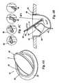
figures 3A, 3B , thedocking apparatus 10 comprises abase 20 consisting of an annularperipheral lip 22 from the inner edge of which depends askirt 24 which together ensure that the base can be securely inserted in push-fit manner into the aperture 4 defined in thedashboard 2, and is prevented from falling therethrough by said lip which is supported by anupper surface 2A of the dashboard. Referring back toFigure 1B , it can be seen that thebase 20 is provided withdeflectable tabs 26 havinghook formations 28 which lock behind alower surface 2B of said dashboard. - In the described embodiment, an
intermediate component 30 is provided within thebase 20 and is secured therein in push-fit manner. Said intermediate component is substantially hemi-spherical in shape defining aninner cavity 32 therein to which access is had through theaperture 12. Within the intermediate component is provided a mounting part indicated generally at 40 which comprises acover part 42 having anupper surface 42A to which the trimmeddisc 6 is secured, and alower surface 42B from which afin part 44 depends. Said fin part may be suitably attached to said cover part, for example by being integrally formed therewith. Provided on one side of thefin part 44 is aconnector 46, which may be for example a commonly known "D-type" or other suitable connector, which may be simply mounted or adhered in place, or alternatively connected to a corresponding connector, possibly provided in a mounted printedcircuitboard 48. The supply of electric power, or other electric or electronic signals to said connector is provided throughcable 47. Anaperture 50 provided in thefin part 44 exposes afurther connector 52 by means of which electric/electronic connection may be achieved with the portable device. - In accordance with the invention, the mounting
part 40 is pivotally mounted about an axis indicated at 54, in this embodiment, in theintermediate part 30, although it should be mentioned that the intermediate component is optional, and the mounting part may be directly pivotally mounted within thebase 20. - As previously mentioned, the mounting part can adopt two positions, a first of which is shown in
Figure 3B . It is retained in this position by means of a push-cam mechanism shown in greater detail inFigure 4C . To operate the docking apparatus such that theconnector 52 becomes exposed, a user applies downward pressure as indicated byarrows 58 to release the push-cam mechanism, whereupon, the cover part, fin part, and associated connectors can pivot within the intermediate component (or base) until the fin comes into substantially co-planar relationship with thelip 22 of thebase 20. The pivoting motion and the exposure of the connectors is clearly shown inFigures 4A , B, and the motion of a typical push-cam mechanism, known and easily implementible by one skilled in the art, is clearly shown inFigure 4C . Again with reference tofigure 3B , a simple slidinglock mechanism 60 is provided at the remote end of thefin part 44 to enable the releasable retention of the mountingpart 40 in its second position, shown inFigures 5A , B, C. Furthermore, the reader will note the provision of connection features 62 such as ribs, grooves, channels, or the like on theunderside 42B of thecover part 42. It is to be mentioned that any type of connection feature may be provided, but in this embodiment, and as can more clearly be seen inFigure 5A , the connection features 62 are in the form of a pair of substantially parallel guide rails which cooperate with a pair of correspondingly shaped grooves on the rear surface of a PND or other portable device. It can also be seen fromFigure 5A that the slidinglock 60 is clearly accessible to a user, whereby the mounting part may be secured in the second "open" position in which a portion of thecover part 42 extends upwardly from thedocking apparatus 10 at a slight angle to the vertical such that any device mounted thereon is also appropriately inclined for ease of view or use, particularly when the portable device includes a visual display. The position and exposure of theconnector 52 is to be noted, proximate the lower reaches of the connection features 62, such that sliding fitment of a portable device thereon automatically aligns theconnector 52 with the corresponding connector (not shown) provided on the base of the portable device, both connectors ultimately mating when the portable device is completely and properly mounted on saidcover part 42. As may also be seen in the enlarged view inFigure 5C , thelock 60 consists of a simple slider which can be moved back and forth, in one of which positions the slider engages within asuitable detent 61 provided in theintermediate component 30 to prevent further pivoting motion of the mountingpart 20 and to lock said mounting part in the second, "open" position. Figure 6 clearly shows aportable navigation device 70 mounted in place on thedocking apparatus 10. An optional feature which may be incorporated into the docking apparatus is the facility for the mounting part to swivel as indicated byarrows cover part 42 to the intermediate component or the base as the case may be.- In
Figures 7A , B, C, there is provided an alternative arrangement wherein anadapter 80 is provided having afirst connector 82 complementary to theconnector 52 exposed through the aperture to the underside offin 44 of thedocking apparatus 10, and asecond connector 84 which is complementary to the connector (not shown) on the underside of theportable device 70. Additionally, connection means 86 are provided to the rear of theadapter 80 which are complementary to the connection features 62 provided on the exposed surface of thecover part 42, and suitable connection features 88 are provided on the alternate face which allow for the sliding connection of theportable device 70, again included corresponding and complementary connection features (not shown) in its rear surface. The adapter may either be of the type shown inFigure 7A which is sufficiently discreet to be fitted to theupstanding cover part 42 and to complete an electrical connection between theconnector 82 and theconnector 52 without impeding the pivotal movement of the mounting part, as shown inFigures 8A, 8B , or the adapter may be of analternative type 90 shown inFigure 7B and8C , which includestabs connector 96 complementary to theconnector 52. However, in analogous manner to theadapter 80, sliding fit ofadapter 90 to thecover part 42 is still required for respective connection ofconnectors Figure 7C . As can be seen inFigure 8D , the adapter is too large to be concealed within the docking apparatus. - Finally, referring to
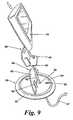
Figure 9 , in an alternative aspect of the invention, thefin 44 of the mounting part is merely provided with anaperture 50 through which thecable 47 may pass, theconnector 46 at the end thereof merely being manually attached to the corresponding andcomplementary connector 82 of theadapter 80.
Claims (16)
- A docking apparatus (10) for a portable device (70), said docking apparatus comprising at least a base (20) and a mounting part (40) which is connected to the base, wherein
the mounting part (40) is pivotally mounted (54) within the base (20) and consists of at least a cover part (42) which in a first position lies substantially flush with the base (20), said cover part (42) capable of being pivoted to a second position wherein part of the cover part (42) extends substantially upwardly from the docking apparatus (10), said pivotal motion also revealing a fin part (44) attached to the underside of said cover part (42), and wherein at least one of- the part of the cover part (42) underside, and- the fin part (44)which are exposed in the second position is provided with one or more cooperating connection features (62) which cooperate with corresponding features provided on the portable device (70) to facilitate the connection of the latter to the formercharacterized in that
said fin part (44) in said second position lies substantially flush with said base (20). - A docking apparatus according to claim 1 wherein the base (20) is additionally provided with a partial or continuous peripheral lip (22) to the inside of which depends a skirt (24) capable of being inserted through an aperture (4) in a mounting surface (2) thereby securing the base to said surface (2), said lip (22) preventing the base (20) from falling through said aperture (4).
- A docking apparatus (10) according to any preceding claim wherein the base (20) and the mounting part (40) are substantially circular in cross-section.
- A docking apparatus (10) according to any preceding claim wherein at least one of the mounting part (40) and the base (20) includes push-release means (56) which in their locked condition secure the mounting part (40) in the first position, and in their released condition allow pivotal movement of said mounting part (40).
- A docking apparatus (10) according to any preceding claim wherein the base (20) and the fin part (44) include cooperating locking means (60, 61) which facilitate the locking of the fin part (44) to the base to secure the mounting part (40) in the second position.
- A docking apparatus (10) according to any preceding claim wherein an intermediate base part (30) is provided within which the mounting part (40) is pivotally mounted, said intermediate base part being secured to the base (20) in a push-fit manner.
- A docking apparatus (10) according to claim 6 wherein at least one of the mounting part (40) and the intermediate base part (30) includes push-release means (56) which in their locked condition secure the mounting part (40) in the first position, and in their released condition allow pivotal movement of said mounting part (40) relative to said intermediate base part (30).
- A docking apparatus (10) according to claim 6 or 7 wherein at least one of the intermediate base part (30) and the fin part (44) of the mounting part (40) include cooperating locking means (60, 61) which facilitate the locking of the fin part (44) to the intermediate base part (30) thus securing the mounting part (40) in the second position.
- A docking apparatus (10) according to any of claims 6-8 wherein the mounting part (40) is both pivotally and rotationally mounted in said intermediate base part (30).
- A docking apparatus (10) according to any of claims 1-5 wherein the mounting part (40) is both pivotally and rotationally mounted in said base part (20).
- A docking apparatus (10) according to any preceding claim wherein cooperating connection features (62) are provided on the underside of the cover part (42) of the mounting part (40), such allowing the portable device (70) to be slidingly connected to said cover part (42) when disposed in an upward condition when the mounting part (40) is in the second position.
- A docking apparatus (10) according to claim 11 wherein the fin part (44) is provided with at least an aperture (50) and an electrical connector (46) disposed behind said aperture (50) such that sliding connection of the portable device (70) thereto automatically align the electrical connector (46) with a corresponding connector provided on the portable device (70) and ultimately achieves sound electrical connection therebetween.
- A docking apparatus (10) according to any preceding claim which includes voltage conversion electronics.
- A docking apparatus (10) according to any preceding claim which further includes a data bus connector.
- A docking apparatus (10) according to claim 14 wherein the bus connector is a universal serial bus (USB) connector.
- A docking apparatus (10) according to any preceding claim wherein the cooperating connection features (62) consist of guide rails.
Applications Claiming Priority (1)
| Application Number | Priority Date | Filing Date | Title |
|---|---|---|---|
| PCT/EP2007/008734WO2009043367A1 (en) | 2007-10-05 | 2007-10-05 | Docking apparatus for portable device |
Publications (2)
| Publication Number | Publication Date |
|---|---|
| EP2193049A1 EP2193049A1 (en) | 2010-06-09 |
| EP2193049B1true EP2193049B1 (en) | 2011-09-14 |
Family
ID=38658148
Family Applications (1)
| Application Number | Title | Priority Date | Filing Date |
|---|---|---|---|
| EP07818808ANot-in-forceEP2193049B1 (en) | 2007-10-05 | 2007-10-05 | Docking apparatus for portable device |
Country Status (7)
| Country | Link |
|---|---|
| EP (1) | EP2193049B1 (en) |
| JP (1) | JP2010540327A (en) |
| CN (1) | CN101815633B (en) |
| AT (1) | ATE524352T1 (en) |
| AU (1) | AU2007359642A1 (en) |
| CA (1) | CA2701250A1 (en) |
| WO (1) | WO2009043367A1 (en) |
Cited By (1)
| Publication number | Priority date | Publication date | Assignee | Title |
|---|---|---|---|---|
| DE102015200305A1 (en)* | 2015-01-13 | 2016-07-14 | Volkswagen Aktiengesellschaft | Holding device for an electronic mobile device |
Families Citing this family (13)
| Publication number | Priority date | Publication date | Assignee | Title |
|---|---|---|---|---|
| ES1066184Y (en)* | 2007-09-28 | 2008-03-16 | Seat Sa | UNIVERSAL SUPPORT FOR ASSEMBLY OF GPS NAVIGATORS IN CARS |
| GB2464352A (en)* | 2008-10-17 | 2010-04-21 | Native Design Ltd | Media player support |
| JP2011005944A (en)* | 2009-06-25 | 2011-01-13 | Nifco Inc | On-vehicle cable holder |
| WO2011034441A1 (en)* | 2009-09-17 | 2011-03-24 | Modulprodukter As | System for universal console for mobile telephones |
| US9140562B2 (en)* | 2011-03-24 | 2015-09-22 | Claude Mignen | System and method for transferring vehicle operating data to an external navigation system |
| DE102011084500A1 (en)* | 2011-10-14 | 2013-04-18 | Ford Global Technologies, Llc | Use for a dashboard |
| EP2738073B1 (en)* | 2012-03-02 | 2019-11-27 | Honda Motor Co., Ltd. | Saddle-type vehicle |
| JP5970697B2 (en)* | 2012-03-28 | 2016-08-17 | トヨタ車体株式会社 | Vehicle tray |
| GB201306995D0 (en)* | 2013-04-17 | 2013-05-29 | Tomtom Int Bv | Mount for portable electronic devices |
| EP3177486B1 (en)* | 2014-08-06 | 2018-09-26 | Johnson Controls Technology Company | Mobile device holder for use in a vehicle |
| FR3036070B1 (en)* | 2015-05-11 | 2018-07-27 | Faurecia Interieur Industrie | VEHICLE INTERIOR EQUIPMENT WITH ACCESSORY SUPPORT |
| FR3090528B1 (en)* | 2018-12-20 | 2020-11-27 | Psa Automobiles Sa | SUPPORT INTEGRATED IN THE DASHBOARD OF A VEHICLE TO MAINTAIN A MULTIMEDIA DEVICE AND CORRESPONDING DASHBOARD |
| ES2804620B2 (en)* | 2019-08-06 | 2022-05-24 | Seat Sa | Center console for a vehicle |
Family Cites Families (11)
| Publication number | Priority date | Publication date | Assignee | Title |
|---|---|---|---|---|
| DE4107995C2 (en)* | 1991-03-13 | 1995-04-13 | Aeg Mobile Communication | Vehicle holder for a handheld radio |
| DE19631444A1 (en)* | 1996-08-03 | 1998-08-13 | Henryk Dipl Ing Bury | Hands-free system for telephones in motor vehicles |
| DE19817346B4 (en)* | 1998-04-18 | 2007-08-09 | Volkswagen Ag | Vehicle console with a holding device for a car phone |
| DE19817345B4 (en)* | 1998-04-18 | 2007-12-27 | Volkswagen Ag | Vehicle console with a swivel mount for a car phone |
| US20070171316A1 (en)* | 1998-12-28 | 2007-07-26 | Johnson Controls Technology Company | Video display system for a vehicle |
| DE19951968A1 (en)* | 1999-10-28 | 2001-05-03 | Bayerische Motoren Werke Ag | Multifunctional module for interior of vehicle, including rotatable equipment module in dashboard or center console |
| US6377825B1 (en)* | 2000-02-18 | 2002-04-23 | Cellport Systems, Inc. | Hands-free wireless communication in a vehicle |
| WO2002058408A2 (en)* | 2001-01-18 | 2002-07-25 | Peiker, Andreas | Assembly comprising a mobile telephone |
| US6692053B1 (en)* | 2002-01-04 | 2004-02-17 | Johnson Controls Technology Company | Dual purpose storage and holding system |
| DE102006008420A1 (en)* | 2006-02-23 | 2007-08-30 | Leopold Kostal Gmbh & Co. Kg | Electronic appliance holder, for a vehicle dashboard, is at an open compartment which is closed for concealment when not in use |
| US8210605B2 (en)* | 2006-03-21 | 2012-07-03 | Be Aerospace, Inc. | Holster for portable IFE device |
- 2007
- 2007-10-05WOPCT/EP2007/008734patent/WO2009043367A1/enactiveApplication Filing
- 2007-10-05ATAT07818808Tpatent/ATE524352T1/ennot_activeIP Right Cessation
- 2007-10-05CACA2701250Apatent/CA2701250A1/ennot_activeAbandoned
- 2007-10-05CNCN2007801009340Apatent/CN101815633B/ennot_activeExpired - Fee Related
- 2007-10-05AUAU2007359642Apatent/AU2007359642A1/ennot_activeAbandoned
- 2007-10-05EPEP07818808Apatent/EP2193049B1/ennot_activeNot-in-force
- 2007-10-05JPJP2010527325Apatent/JP2010540327A/ennot_activeWithdrawn
Cited By (1)
| Publication number | Priority date | Publication date | Assignee | Title |
|---|---|---|---|---|
| DE102015200305A1 (en)* | 2015-01-13 | 2016-07-14 | Volkswagen Aktiengesellschaft | Holding device for an electronic mobile device |
Also Published As
| Publication number | Publication date |
|---|---|
| CA2701250A1 (en) | 2009-04-09 |
| JP2010540327A (en) | 2010-12-24 |
| CN101815633B (en) | 2013-06-05 |
| ATE524352T1 (en) | 2011-09-15 |
| AU2007359642A1 (en) | 2009-04-09 |
| CN101815633A (en) | 2010-08-25 |
| EP2193049A1 (en) | 2010-06-09 |
| WO2009043367A1 (en) | 2009-04-09 |
Similar Documents
| Publication | Publication Date | Title |
|---|---|---|
| US8159818B2 (en) | Docking apparatus for portable device | |
| EP2193049B1 (en) | Docking apparatus for portable device | |
| US20180215325A1 (en) | Vehicle mounting system for mobile computing devices | |
| US6956628B2 (en) | View angle-adjustable detachable display assembly | |
| US20080157574A1 (en) | Dockable media system | |
| US5555491A (en) | Compact docking station for portable computer | |
| US9180803B2 (en) | Rear pass through power outlet | |
| US7176987B2 (en) | Portable DVD player and console arrangement | |
| US20140006669A1 (en) | Retractable device dock | |
| US20070038434A1 (en) | Universal system interface | |
| US8550410B2 (en) | Mobile electronic device (MED) mounting and positioning bracket assembly | |
| US20050204596A1 (en) | Portable seat back display | |
| US20090108151A1 (en) | Transparent suction cup mounting platform | |
| US20090089841A1 (en) | Seat-mounted electronics assembly | |
| US9665961B2 (en) | Intelligent mirror | |
| US20080200217A1 (en) | Hands-free installation | |
| JP2007112200A (en) | Inner mirror | |
| EP1581985A1 (en) | Modular electronic systems for vehicles | |
| US20090233481A1 (en) | Vehicle | |
| GB2483853A (en) | Flexible mounting for personal electronic item in vehicle interior | |
| HK1143119A (en) | Docking apparatus for portable device | |
| KR100892125B1 (en) | Mounting device for mobile multimedia player | |
| JP2009262773A (en) | Mobile type electronic device and device fitting stand | |
| JP2000142244A (en) | Center console structure | |
| EP1592582B1 (en) | Installation module |
Legal Events
| Date | Code | Title | Description |
|---|---|---|---|
| PUAI | Public reference made under article 153(3) epc to a published international application that has entered the european phase | Free format text:ORIGINAL CODE: 0009012 | |
| 17P | Request for examination filed | Effective date:20100326 | |
| AK | Designated contracting states | Kind code of ref document:A1 Designated state(s):AT BE BG CH CY CZ DE DK EE ES FI FR GB GR HU IE IS IT LI LT LU LV MC MT NL PL PT RO SE SI SK TR | |
| AX | Request for extension of the european patent | Extension state:AL BA HR MK RS | |
| GRAP | Despatch of communication of intention to grant a patent | Free format text:ORIGINAL CODE: EPIDOSNIGR1 | |
| DAX | Request for extension of the european patent (deleted) | ||
| GRAS | Grant fee paid | Free format text:ORIGINAL CODE: EPIDOSNIGR3 | |
| GRAA | (expected) grant | Free format text:ORIGINAL CODE: 0009210 | |
| RAP1 | Party data changed (applicant data changed or rights of an application transferred) | Owner name:TOMTOM INTERNATIONAL B.V. | |
| AK | Designated contracting states | Kind code of ref document:B1 Designated state(s):AT BE BG CH CY CZ DE DK EE ES FI FR GB GR HU IE IS IT LI LT LU LV MC MT NL PL PT RO SE SI SK TR | |
| REG | Reference to a national code | Ref country code:GB Ref legal event code:FG4D | |
| REG | Reference to a national code | Ref country code:CH Ref legal event code:EP | |
| REG | Reference to a national code | Ref country code:IE Ref legal event code:FG4D | |
| REG | Reference to a national code | Ref country code:DE Ref legal event code:R096 Ref document number:602007017235 Country of ref document:DE Effective date:20111110 | |
| REG | Reference to a national code | Ref country code:NL Ref legal event code:T3 | |
| RAP2 | Party data changed (patent owner data changed or rights of a patent transferred) | Owner name:TOMTOM INTERNATIONAL B.V. | |
| PG25 | Lapsed in a contracting state [announced via postgrant information from national office to epo] | Ref country code:SE Free format text:LAPSE BECAUSE OF FAILURE TO SUBMIT A TRANSLATION OF THE DESCRIPTION OR TO PAY THE FEE WITHIN THE PRESCRIBED TIME-LIMIT Effective date:20110914 Ref country code:LT Free format text:LAPSE BECAUSE OF FAILURE TO SUBMIT A TRANSLATION OF THE DESCRIPTION OR TO PAY THE FEE WITHIN THE PRESCRIBED TIME-LIMIT Effective date:20110914 Ref country code:FI Free format text:LAPSE BECAUSE OF FAILURE TO SUBMIT A TRANSLATION OF THE DESCRIPTION OR TO PAY THE FEE WITHIN THE PRESCRIBED TIME-LIMIT Effective date:20110914 | |
| LTIE | Lt: invalidation of european patent or patent extension | Effective date:20110914 | |
| PG25 | Lapsed in a contracting state [announced via postgrant information from national office to epo] | Ref country code:SI Free format text:LAPSE BECAUSE OF FAILURE TO SUBMIT A TRANSLATION OF THE DESCRIPTION OR TO PAY THE FEE WITHIN THE PRESCRIBED TIME-LIMIT Effective date:20110914 Ref country code:LV Free format text:LAPSE BECAUSE OF FAILURE TO SUBMIT A TRANSLATION OF THE DESCRIPTION OR TO PAY THE FEE WITHIN THE PRESCRIBED TIME-LIMIT Effective date:20110914 Ref country code:AT Free format text:LAPSE BECAUSE OF FAILURE TO SUBMIT A TRANSLATION OF THE DESCRIPTION OR TO PAY THE FEE WITHIN THE PRESCRIBED TIME-LIMIT Effective date:20110914 Ref country code:GR Free format text:LAPSE BECAUSE OF FAILURE TO SUBMIT A TRANSLATION OF THE DESCRIPTION OR TO PAY THE FEE WITHIN THE PRESCRIBED TIME-LIMIT Effective date:20111215 Ref country code:CY Free format text:LAPSE BECAUSE OF FAILURE TO SUBMIT A TRANSLATION OF THE DESCRIPTION OR TO PAY THE FEE WITHIN THE PRESCRIBED TIME-LIMIT Effective date:20110914 | |
| REG | Reference to a national code | Ref country code:AT Ref legal event code:MK05 Ref document number:524352 Country of ref document:AT Kind code of ref document:T Effective date:20110914 | |
| PG25 | Lapsed in a contracting state [announced via postgrant information from national office to epo] | Ref country code:BE Free format text:LAPSE BECAUSE OF FAILURE TO SUBMIT A TRANSLATION OF THE DESCRIPTION OR TO PAY THE FEE WITHIN THE PRESCRIBED TIME-LIMIT Effective date:20110914 | |
| PG25 | Lapsed in a contracting state [announced via postgrant information from national office to epo] | Ref country code:IS Free format text:LAPSE BECAUSE OF FAILURE TO SUBMIT A TRANSLATION OF THE DESCRIPTION OR TO PAY THE FEE WITHIN THE PRESCRIBED TIME-LIMIT Effective date:20120114 Ref country code:SK Free format text:LAPSE BECAUSE OF FAILURE TO SUBMIT A TRANSLATION OF THE DESCRIPTION OR TO PAY THE FEE WITHIN THE PRESCRIBED TIME-LIMIT Effective date:20110914 Ref country code:CZ Free format text:LAPSE BECAUSE OF FAILURE TO SUBMIT A TRANSLATION OF THE DESCRIPTION OR TO PAY THE FEE WITHIN THE PRESCRIBED TIME-LIMIT Effective date:20110914 | |
| PG25 | Lapsed in a contracting state [announced via postgrant information from national office to epo] | Ref country code:IT Free format text:LAPSE BECAUSE OF FAILURE TO SUBMIT A TRANSLATION OF THE DESCRIPTION OR TO PAY THE FEE WITHIN THE PRESCRIBED TIME-LIMIT Effective date:20110914 Ref country code:MC Free format text:LAPSE BECAUSE OF NON-PAYMENT OF DUE FEES Effective date:20111031 Ref country code:PL Free format text:LAPSE BECAUSE OF FAILURE TO SUBMIT A TRANSLATION OF THE DESCRIPTION OR TO PAY THE FEE WITHIN THE PRESCRIBED TIME-LIMIT Effective date:20110914 Ref country code:EE Free format text:LAPSE BECAUSE OF FAILURE TO SUBMIT A TRANSLATION OF THE DESCRIPTION OR TO PAY THE FEE WITHIN THE PRESCRIBED TIME-LIMIT Effective date:20110914 Ref country code:PT Free format text:LAPSE BECAUSE OF FAILURE TO SUBMIT A TRANSLATION OF THE DESCRIPTION OR TO PAY THE FEE WITHIN THE PRESCRIBED TIME-LIMIT Effective date:20120116 Ref country code:RO Free format text:LAPSE BECAUSE OF FAILURE TO SUBMIT A TRANSLATION OF THE DESCRIPTION OR TO PAY THE FEE WITHIN THE PRESCRIBED TIME-LIMIT Effective date:20110914 | |
| REG | Reference to a national code | Ref country code:CH Ref legal event code:PL | |
| PLBE | No opposition filed within time limit | Free format text:ORIGINAL CODE: 0009261 | |
| STAA | Information on the status of an ep patent application or granted ep patent | Free format text:STATUS: NO OPPOSITION FILED WITHIN TIME LIMIT | |
| PG25 | Lapsed in a contracting state [announced via postgrant information from national office to epo] | Ref country code:CH Free format text:LAPSE BECAUSE OF NON-PAYMENT OF DUE FEES Effective date:20111031 Ref country code:DK Free format text:LAPSE BECAUSE OF FAILURE TO SUBMIT A TRANSLATION OF THE DESCRIPTION OR TO PAY THE FEE WITHIN THE PRESCRIBED TIME-LIMIT Effective date:20110914 Ref country code:LI Free format text:LAPSE BECAUSE OF NON-PAYMENT OF DUE FEES Effective date:20111031 | |
| REG | Reference to a national code | Ref country code:IE Ref legal event code:MM4A | |
| 26N | No opposition filed | Effective date:20120615 | |
| REG | Reference to a national code | Ref country code:DE Ref legal event code:R097 Ref document number:602007017235 Country of ref document:DE Effective date:20120615 | |
| PG25 | Lapsed in a contracting state [announced via postgrant information from national office to epo] | Ref country code:IE Free format text:LAPSE BECAUSE OF NON-PAYMENT OF DUE FEES Effective date:20111005 | |
| PG25 | Lapsed in a contracting state [announced via postgrant information from national office to epo] | Ref country code:MT Free format text:LAPSE BECAUSE OF FAILURE TO SUBMIT A TRANSLATION OF THE DESCRIPTION OR TO PAY THE FEE WITHIN THE PRESCRIBED TIME-LIMIT Effective date:20110914 | |
| PG25 | Lapsed in a contracting state [announced via postgrant information from national office to epo] | Ref country code:LU Free format text:LAPSE BECAUSE OF NON-PAYMENT OF DUE FEES Effective date:20111005 | |
| PG25 | Lapsed in a contracting state [announced via postgrant information from national office to epo] | Ref country code:BG Free format text:LAPSE BECAUSE OF FAILURE TO SUBMIT A TRANSLATION OF THE DESCRIPTION OR TO PAY THE FEE WITHIN THE PRESCRIBED TIME-LIMIT Effective date:20111214 | |
| PG25 | Lapsed in a contracting state [announced via postgrant information from national office to epo] | Ref country code:TR Free format text:LAPSE BECAUSE OF FAILURE TO SUBMIT A TRANSLATION OF THE DESCRIPTION OR TO PAY THE FEE WITHIN THE PRESCRIBED TIME-LIMIT Effective date:20110914 | |
| PG25 | Lapsed in a contracting state [announced via postgrant information from national office to epo] | Ref country code:ES Free format text:LAPSE BECAUSE OF FAILURE TO SUBMIT A TRANSLATION OF THE DESCRIPTION OR TO PAY THE FEE WITHIN THE PRESCRIBED TIME-LIMIT Effective date:20111225 Ref country code:HU Free format text:LAPSE BECAUSE OF FAILURE TO SUBMIT A TRANSLATION OF THE DESCRIPTION OR TO PAY THE FEE WITHIN THE PRESCRIBED TIME-LIMIT Effective date:20110914 | |
| REG | Reference to a national code | Ref country code:FR Ref legal event code:PLFP Year of fee payment:9 | |
| REG | Reference to a national code | Ref country code:FR Ref legal event code:PLFP Year of fee payment:10 | |
| REG | Reference to a national code | Ref country code:FR Ref legal event code:PLFP Year of fee payment:11 | |
| REG | Reference to a national code | Ref country code:FR Ref legal event code:PLFP Year of fee payment:12 | |
| PGFP | Annual fee paid to national office [announced via postgrant information from national office to epo] | Ref country code:FR Payment date:20220921 Year of fee payment:16 | |
| PGFP | Annual fee paid to national office [announced via postgrant information from national office to epo] | Ref country code:NL Payment date:20230915 Year of fee payment:17 Ref country code:GB Payment date:20230831 Year of fee payment:17 | |
| PGFP | Annual fee paid to national office [announced via postgrant information from national office to epo] | Ref country code:DE Payment date:20230906 Year of fee payment:17 | |
| PG25 | Lapsed in a contracting state [announced via postgrant information from national office to epo] | Ref country code:FR Free format text:LAPSE BECAUSE OF NON-PAYMENT OF DUE FEES Effective date:20231031 | |
| REG | Reference to a national code | Ref country code:DE Ref legal event code:R119 Ref document number:602007017235 Country of ref document:DE | |
| REG | Reference to a national code | Ref country code:NL Ref legal event code:MM Effective date:20241101 | |
| GBPC | Gb: european patent ceased through non-payment of renewal fee | Effective date:20241005 | |
| PG25 | Lapsed in a contracting state [announced via postgrant information from national office to epo] | Ref country code:DE Free format text:LAPSE BECAUSE OF NON-PAYMENT OF DUE FEES Effective date:20250501 | |
| PG25 | Lapsed in a contracting state [announced via postgrant information from national office to epo] | Ref country code:GB Free format text:LAPSE BECAUSE OF NON-PAYMENT OF DUE FEES Effective date:20241005 | |
| PG25 | Lapsed in a contracting state [announced via postgrant information from national office to epo] | Ref country code:NL Free format text:LAPSE BECAUSE OF NON-PAYMENT OF DUE FEES Effective date:20241101 |