EP2191798B1 - Systems and methods for power and flow rate control - Google Patents
Systems and methods for power and flow rate controlDownload PDFInfo
- Publication number
- EP2191798B1 EP2191798B1EP10153823AEP10153823AEP2191798B1EP 2191798 B1EP2191798 B1EP 2191798B1EP 10153823 AEP10153823 AEP 10153823AEP 10153823 AEP10153823 AEP 10153823AEP 2191798 B1EP2191798 B1EP 2191798B1
- Authority
- EP
- European Patent Office
- Prior art keywords
- aspiration
- vacuum
- occlusion
- fluid
- line
- Prior art date
- Legal status (The legal status is an assumption and is not a legal conclusion. Google has not performed a legal analysis and makes no representation as to the accuracy of the status listed.)
- Not-in-force
Links
- 238000000034methodMethods0.000titleclaimsabstractdescription33
- 239000012530fluidSubstances0.000claimsabstractdescription72
- 238000011144upstream manufacturingMethods0.000claimsabstract2
- 230000002262irrigationEffects0.000claimsdescription38
- 238000003973irrigationMethods0.000claimsdescription38
- 238000001356surgical procedureMethods0.000claimsdescription9
- 238000004590computer programMethods0.000claimsdescription8
- 230000008569processEffects0.000claimsdescription7
- 238000010438heat treatmentMethods0.000claimsdescription3
- 230000008030eliminationEffects0.000abstractdescription2
- 238000003379elimination reactionMethods0.000abstractdescription2
- 238000010586diagramMethods0.000description11
- 230000037361pathwayEffects0.000description6
- 238000013459approachMethods0.000description5
- 230000008859changeEffects0.000description5
- 210000002159anterior chamberAnatomy0.000description4
- 238000001514detection methodMethods0.000description4
- 230000002572peristaltic effectEffects0.000description4
- 230000008901benefitEffects0.000description3
- 230000004044responseEffects0.000description3
- 230000006378damageEffects0.000description2
- 238000003780insertionMethods0.000description2
- 230000037431insertionEffects0.000description2
- 239000007788liquidSubstances0.000description2
- 239000000463materialSubstances0.000description2
- 208000002177CataractDiseases0.000description1
- FAPWRFPIFSIZLT-UHFFFAOYSA-MSodium chlorideChemical compound[Na+].[Cl-]FAPWRFPIFSIZLT-UHFFFAOYSA-M0.000description1
- 208000027418Wounds and injuryDiseases0.000description1
- 230000004075alterationEffects0.000description1
- 230000000903blocking effectEffects0.000description1
- 230000017531blood circulationEffects0.000description1
- 238000004891communicationMethods0.000description1
- 239000013078crystalSubstances0.000description1
- 238000005520cutting processMethods0.000description1
- 238000000502dialysisMethods0.000description1
- 238000006073displacement reactionMethods0.000description1
- 230000009977dual effectEffects0.000description1
- 238000004945emulsificationMethods0.000description1
- 208000014674injuryDiseases0.000description1
- 238000013532laser treatmentMethods0.000description1
- 238000004890maltingMethods0.000description1
- 238000004519manufacturing processMethods0.000description1
- 238000005259measurementMethods0.000description1
- 238000012986modificationMethods0.000description1
- 230000004048modificationEffects0.000description1
- 238000012544monitoring processMethods0.000description1
- 239000002245particleSubstances0.000description1
- 230000010363phase shiftEffects0.000description1
- 125000006850spacer groupChemical group0.000description1
- 230000008733traumaEffects0.000description1
- 238000011282treatmentMethods0.000description1
- 238000013022ventingMethods0.000description1
- 230000000007visual effectEffects0.000description1
- XLYOFNOQVPJJNP-UHFFFAOYSA-NwaterSubstancesOXLYOFNOQVPJJNP-UHFFFAOYSA-N0.000description1
Images


Classifications
- A—HUMAN NECESSITIES
- A61—MEDICAL OR VETERINARY SCIENCE; HYGIENE
- A61F—FILTERS IMPLANTABLE INTO BLOOD VESSELS; PROSTHESES; DEVICES PROVIDING PATENCY TO, OR PREVENTING COLLAPSING OF, TUBULAR STRUCTURES OF THE BODY, e.g. STENTS; ORTHOPAEDIC, NURSING OR CONTRACEPTIVE DEVICES; FOMENTATION; TREATMENT OR PROTECTION OF EYES OR EARS; BANDAGES, DRESSINGS OR ABSORBENT PADS; FIRST-AID KITS
- A61F9/00—Methods or devices for treatment of the eyes; Devices for putting in contact-lenses; Devices to correct squinting; Apparatus to guide the blind; Protective devices for the eyes, carried on the body or in the hand
- A61F9/007—Methods or devices for eye surgery
- A61F9/00736—Instruments for removal of intra-ocular material or intra-ocular injection, e.g. cataract instruments
- A—HUMAN NECESSITIES
- A61—MEDICAL OR VETERINARY SCIENCE; HYGIENE
- A61M—DEVICES FOR INTRODUCING MEDIA INTO, OR ONTO, THE BODY; DEVICES FOR TRANSDUCING BODY MEDIA OR FOR TAKING MEDIA FROM THE BODY; DEVICES FOR PRODUCING OR ENDING SLEEP OR STUPOR
- A61M1/00—Suction or pumping devices for medical purposes; Devices for carrying-off, for treatment of, or for carrying-over, body-liquids; Drainage systems
- A61M1/71—Suction drainage systems
- A61M1/74—Suction control
- A61M1/743—Suction control by changing the cross-section of the line, e.g. flow regulating valves
- A—HUMAN NECESSITIES
- A61—MEDICAL OR VETERINARY SCIENCE; HYGIENE
- A61B—DIAGNOSIS; SURGERY; IDENTIFICATION
- A61B17/00—Surgical instruments, devices or methods
- A61B2017/00017—Electrical control of surgical instruments
- A61B2017/00022—Sensing or detecting at the treatment site
- A61B2017/00084—Temperature
- A—HUMAN NECESSITIES
- A61—MEDICAL OR VETERINARY SCIENCE; HYGIENE
- A61M—DEVICES FOR INTRODUCING MEDIA INTO, OR ONTO, THE BODY; DEVICES FOR TRANSDUCING BODY MEDIA OR FOR TAKING MEDIA FROM THE BODY; DEVICES FOR PRODUCING OR ENDING SLEEP OR STUPOR
- A61M1/00—Suction or pumping devices for medical purposes; Devices for carrying-off, for treatment of, or for carrying-over, body-liquids; Drainage systems
- A61M1/71—Suction drainage systems
- A61M1/77—Suction-irrigation systems
Definitions
- the field of the inventionrelates to systems and methods for fluid control, and more particularly to systems and methods for power and flow rate control.
- a number of medically recognized techniquesare utilized for cataractic lens removal based on, for example, phacoemulsification, mechanical cutting or destruction, laser treatments, water jet treatments, and so on.
- the phacoemulsification methodincludes malting a corneal incision and the insertion of a phacoemulsification handpiece which includes a needle that is ultrasonically driven in order to emulsify, or liquefy, the lens.
- a phacoemulsification system 5 known in the artis shown in Fig. 1 .
- the system 5generally includes a phacemulsification handpiece 20 coupled to an irrigation source 30 and an aspiration pump 40.
- the handpiece 10includes a distal tip 15 (shown within the anterior chamber of the patient's eye 1) that emits ultrasonic energy to emulsify the cataractic lens within the patient's eye 1.
- the handpiece 10further includes an irrigation port 25 proximal to the distal tip 15, which is coupled to an irrigation source 30 via an irrigation line 35, and an aspiration port 20 at the distal tip 15, which is coupled to an aspiration pump 40 via an aspiration line 45.
- fluid from the irrigation source 30, which is typically an elevated bottle of saline solutionis irrigated into the eye 1 via the irrigation line 35 and the irrigation port 25, and the irrigation fluid and emulsified cataractic lens material are aspirationd from the eye 1 by the aspiration pump 40 via the aspiration port 20 and the aspiration line 45.
- Other medical techniques for removing cataractic lensesalso typically include irrigating the eye and aspirating lens parts and other liquids. Additionally, some procedures may include irrigating the eye 1 and aspirating the irrigating fluid without concomitant destruction, alteration or removal of the lens.
- Aspirationcan be achieved with a variety of different aspiration pumps 40 known in the art.
- the two most common typesare (1) volumetric flow or positive displacement pumps (such as peristaltic or scroll pumps) and (2) vacuum-based pumps (such as venturi, diaphragm, or rotary-vane pumps).
- Each typehas its own general advantages and disadvantages.
- FIG. 2an example peristaltic flow pump 50 is illustrated.
- the aspiration line 45is in direct contact with a rotating pump head 50 having rollers 52 around its perimeter.
- the rollers 52press against the line 45 causing fluid to flow within the line 45 in the direction of the rollers 52.
- Thisis referred to as a volumetric flow pump because the pump 50 directly controls the volume or rate of fluid flow.
- An advantage with this type of pump 50is that the rate of fluid flow can be easily and precisely controlled by adjusting the rotational speed of the pump head 50.
- the vacuum-based pump 60can be an pneumatic pump (e.g., a venturi pump) that creates a pressure differential in a drainage cassette reservoir 65 that causes the fluid to be sucked from the aspiration line 45 into the drainage cassette reservoir 65.
- a pneumatic pumpe.g., a venturi pump
- the fluidis essentially pulled by vacuum through the line 45.
- the rate of fluid flow generated by a vacuum-based pumpis generally higher than the rate of fluid flow generated by a volumetric flow based pump; however, current systems and methods for controlling the rate of volumetric flow for the vacuum-based pump, which typically involve adjusting the operative vacuum level, are imprecise, which raises safety and efficacy concerns.
- This occlusionis caused by particles blocking a lumen or tube in the aspirating handpiece 10, e.g., the aspiration port 20 or irrigation port 25.
- this blockagecan result in increased vacuum (i.e. increasingly negative pressure) in the aspiration line 45 and the longer the occlusion is in place, the greater the vacuum.
- this blockagecan result in a volumetric fluid flow drop off near the aspiration port 20. In either case, once the occlusion is cleared, a resulting rush of fluid from the anterior chamber into the aspiration line 45 can outpace the volumetric flow of new fluid into the eye 1 from the irrigation source 30.
- post-occlusion surge or fluidic surgein which the structure of the anterior chamber moves rapidly as fluid is replaced due to the dynamic change in the rate of fluid flow and pressure.
- post-occlusion surge eventsmay lead to eye trauma.
- the most common approach to preventing or minimizing the post-occlusion surgeis to quickly adjust the vacuum-level or rate of fluid flow in the aspiration line 45 and/or the ultrasonic power of the handpiece 10 upon detection of an occlusion.
- Many surgeonsrely on their own visual observations to detect the occlusion; however, because of the unpredictable and time-sensitive nature of the problem, a reliable computer-based detection and response system is preferable.
- a computer-based systemcan utilize a vacuum sensor 55 placed on the aspiration line 45 to detect the vacuum increase and respond accordingly (an example of such a system is described in "Barwick” and "Claus").
- the vacuum level within the aspiration line 45is tied to the vacuum power generated by the pump 60 and thus, may not be an effective indicator of whether an occlusion has occurred.
- US 5,487,827discloses a flow sensor comprising first and second thermistors and a controller for determining the flow condition based on the outputs of the thermistors.
- WO 03/047653discloses an ophthalmic surgical pump system having a flow sensor for detecting occlusion of an aspiration pathway. The preamble of claim 1 is based on the WO document.
- the inventionis generally directed to a surgical system for eye surgery.
- the inventionis defined in claim 1.
- the rate of fluid flowis a function of three (3) basic parameters: (1) the effective viscosity of the fluid, (2) the operative or driving vacuum level, and (3) the instantaneous effective resistance of the fluid transport pathway (e.g., aspiration line 45).
- the instantaneous effective resistance of the fluid transport pathwayis a parameter that can vary independent of the vacuum-level, and thus, is not easily quantified or dynamically compensated for in cases such as fluid transport pathway obstruction (e.g., occlusion), which is a significant reason why volumetric flow rate is difficult to control by only adjusting the operative vacuum-level.
- fluid transport pathway obstructione.g., occlusion
- one existing approachis to utilize a fixed flow restrictor (not shown) on the aspiration line 45 between the aspiration port 20 and the pump 60.
- the fixed flow restrictorcan be an orifice within the line 45 that reduces the cross-sectional area of the portion of the line 45 having the orifice.
- variable flow restrictor 150is located on an aspiration line 110 having an aspiration port 120 at its distal end, and a drainage cassette 130 and vacuum pump 140 at its proximal end.
- the variable flow restrictor 150is generally a device, preferably controllable by a computer system (not shown), that variably controls the instantaneous effective resistance of the fluid pathway (e.g., the aspiration line 110) of the system 100. This can allow for precise control of the volumetric flow rate for a vacuum-based pump 140 while still utilizing a wide range of operation.
- variable flow restrictor 150is configured to deform a specific, localized, deformable segment 115 of the aspiration line 110.
- the instantaneous effective resistancecan be increased, which inversely lowers both the current actual volumetric flow race and also the theoretical maximum volumetric flow rate potential of the fluid.
- the segment 115 of the aspiration line 110 coupled to the variable flow restrictor 200is preferably made of an elastomeric deformable tubing having a resistance variability of at least 2:1 (comparing non-derormed vs. maximum deformation cross-sectional profiles).
- the variable flow restrictor 200includes a plunger 210 coupled to an actuator 230 controllable by a computer system (not shown). During operation, the actuator 230 pushes the plunger 210 into mechanical contact with the deformable segment 115 of the aspiration line 110, causing the segment 115 of the aspiration line 110 to deform, thereby adjusting the effective resistance, as explained above.
- the actuator 230can be any type of actuator known in the art, such as a mechanical actuator (e.g., a linear motor, axial solenoid, rotary solenoid, or electro magnetic motor), a pneumatic actuator (e.g., such as a low friction pneumatic rotary or axial bladder/cylinder with a variable pressure supply) or a thermal actuator (e.g., such as a bi-metallic strip).
- a mechanical actuatore.g., a linear motor, axial solenoid, rotary solenoid, or electro magnetic motor
- a pneumatic actuatore.g., such as a low friction pneumatic rotary or axial bladder/cylinder with a variable pressure supply
- a thermal actuatore.g., such as a bi-metallic strip.
- a pneumatic actuatoris preferable because it can be continuously variable, which desirably increases the resolution of the control of the plunger 210 and thus the control of the effective resistance.
- a spacer 220such as a wedge or cam, (also controllable by a computer system (not shown)), can be utilized in between the plunger 210 and the actuator 230 (or behind the actuator 240) to further control the plunger's 210 range of motion, thereby increasing controllability of the effective resistance.
- variable flow restrictor 300is shown coupled to the aspiration line 110 (shown in cross-sectional view).
- This variable flow restrictor 300includes a rigid case 350, having a fixed height, surrounding the line 110.
- the case 350limits the amount of deformation on the line 110.
- the restrictor 300further includes a flat plunger 310 having a width greater than the width of the case 350.
- the plunger 310is coupled to an actuator (not shown) such as the actuator 230 described above. The actuator pushes the plunger 310 into mechanical contact with the line 110, causing the line 110 to deform; however, deformation of the line 110 is limited to the top of the case 350.
- variable flow restrictors 150 that deform segment 115include devices that stretch the segment 115 in the longitudinal direction of the line 110 (not shown) and also devices that twist the segment 115 into a spiral shape (not shown).
- the variable flow restrictor 150can be a device that is integrated with the line 110, for example, a chamber (not shown) within the line 110 with a deformable cross-section.
- the aspiration system 1000includes a flow restrictor 1200, which is preferably a variable flow restrictor but can be a fixed flow restrictor, located on an aspiration line 1110 having an aspiration port 1120 at its distal end and a drainage cassette 1130 and vacuum-based pump 1140 at its proximal end. Further included are first and second vacuum sensors 1300/1350.
- the first vacuum sensor 1300is operatively coupled to the aspiration line 1110 between the port 1120 and the restrictor 1200 ("port 1120 side'), and the second vacuum sensor 1350 is located between the restrictor 1200 and the pump 1140 ("pump 1140 side").
- the flow restrictor 1200will produce a differential volumetric flow rate between the port 1120 side of the line and the pump 1140 side of the line. This accordingly, will cause a vacuum or pressure differential, ⁇ P, between the port 1120 side of the line 1110 and the pump 1140 side of the line.
- the vacuum level, or pressure, on the pump 1140 side of the line 1110will generally be substantially tied to the vacuum level of the pump 1140; however, the vacuum level, or pressure, on the port 1120 side can vary with the volumetric flow rate in the port 1120 side.
- the volumetric flow rate on the port 1120 side of the linewill be reduced, which will in turn reduce the pressure, P port-side, on the port 1120 side of the line, while the vacuum, or pressure, P pump-side: on the pump 1140 side of the line remains substantially tied to the vacuum-level of the pump.
- a ⁇ P (P port-side - P pump-side ) pressure differentialcan be measured and utilized in a computer-based algorithm, such as those described in the Claus and Barwick applications referenced above, to detect the onset, presence, breakage, or elimination of an occlusion.
- the flow restrictor 1200is a variable flow restrictor, then the vacuum-based aspiration system 1000 can provide both computer-based detection of occlusion and precise control of the volumetric flow rate while still maintaining the vacuum-based pump's 1140 full range of operation.
- Another approach to detect the occurrence of an occlusionis to utilize a Doppler flow meter, known in the art, to measure the volumetric flow rate in the aspiration line (not shown).
- a Doppler flow meterknown in the art
- the volumetric flow ratewill decrease, which will be detected by the Doppler flow meter, and the aspiration system (vacuum or flow pump based) can respond accordingly.
- thermodilutionis the measurement of rate of fluid flow in a fluid circuit based on the change in temperature of the fluid from one point of the circuit to another downstream.
- a technique known in the art as thermodilutionis the measurement of rate of fluid flow in a fluid circuit based on the change in temperature of the fluid from one point of the circuit to another downstream.
- a vacuum-based aspiration system 1005is shown having the same parts as aspiration system 1000 except instead of pressure sensors 1300 and 1350, temperature sensors 1500/1600 are used.
- a first temperature sensor 1500 for measuring fluidis coupled to the aspiration line 1110 towards the distal section of the line 1110
- a second temperature sensor 1600is coupled downstream of the first sensor 1500 towards the proximal section of the line 1110.
- the change in temperature, ⁇ T, in the fluid as read by the sensors 1500/1600will correlate with the rate of fluid flow, as one of ordinary skill in the art would appreciate, e.g., a higher rate of fluid flow will cause a smaller change in temperature compared to a lower rate of fluid flow.
- a fluid of a known starting temperatureis injected into the aspiration line 1110.
- a ⁇ Tis measured using the second temperature sensor 1600.
- a heating element 1490is used to heat the fluid within the line 1110 to a desired temperature. Again, ⁇ T is measured using the second temperature sensor 1600.
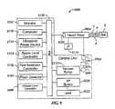
- the system 2000includes a control unit 2102 and a handpiece 2104 operably coupled together.
- the handpiece 2104may include a needle (not shown) for insertion into an eye E and a vibrating unit (not shown) that is configured to ultrasonically vibrate the needle.
- the vibrating unitwhich may include, e.g., a piezoelectric crystal, vibrates the needle according to one or more parameters, such as frequency, pulse width, shape, size, duty cycle, amplitude, and so on.
- the handpiece 2104provides power, P, irrigation fluid, F, from an irrigation fluid ("IF”) source 2128, and an aspiration line A.
- IFirrigation fluid
- the control unit 2102includes a vacuum-based pump 2112 operative coupled to aspiration line A, first and second vacuum sensors 2250/2260 in between the pump 2112 and the handpiece 2104, and a flow restrictor 2270 (which is preferably variable) in between the vacuum sensors 2250/2260.
- the control unit 2102further includes a microprocessor computer 2110 which is operably connected to and controls the various other elements of the system, such as the vacuum-based pump 2112, a vacuum level controller 2200, a pulsed ultrasonic power source 2114, a flow restrictor controller 2116 (which controls the volumetric flow rate of the aspiration line A by controlling the flow restrictor 2270 as described above), and an ultrasonic power level controller 2118 in accordance with algorithms described in the Claus application referenced above.
- a pressure differential ⁇ P sensor 2120provides an input to the computer 2110 representing the pressure differential between the first and second vacuum sensors 2250/2260. Venting may be provided by a vent 2122.
- the control unit 2102may also include a phase detector 2124 for providing an input to the computer 2110 that represents a phase shift between a sine wave representation of the voltage applied to the handpiece 2104 and the resultant current into the handpiece 2104.
- the functional representation of the system 2000also includes a system bus 2126 to enable the various elements to be operably in communication with each other.
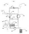
- an irrigation/aspiration cassette 3000(preferably disposable) is shown for use in a surgical system, such as a phacoemulsification system.
- the irrigation/aspiration cassette 3000includes an irrigation source 3100 operatively coupled to a handpiece 3200 via an irrigation line.
- An irrigation valve 3150controls the irrigation source 3100.
- the handpiece 3200is further coupled to the aspiration portion of the cassette 3000 having both a vacuum-based pump 3500 and a flow pump 3300.
- the operation of one or the otheris controlled by a selector valve 3250. When the selector valve 3250 is closed, then the flow pump 3300, which is a first peristaltic pump 3300 is the present embodiment, aspirations the fluid from the handpiece 3200.
- the flow pump 3300pushes the fluid to a holding tank 3450, which is then drained to a collection bag 3600 by a second peristaltic pump.
- a vacuum sensor 3750 communicatively coupled to a computer systemis utilized between the flow pump 3300 and the handpiece 3200 to detect any change in vacuum level, which can indicate a possible occlusion.
- the aspiration portion of the cassette 3000further includes an air filter 3350 and a vent valve 3400, which are utilized by the flow pump 3300 and the vacuum-based pump 3500.
- a flow restrictor 3650preferably variable
- an air transducer 3700operatively located in between the holding tank 3450 and the vacuum pump 3500.
- the flow restrictor 3650enables direct control of the volumetric flow rate, as explained above, and the pressure differential, ⁇ P, can be measured by using both the air-coupled vacuum transducer 3700 and the fluid-coupled vacuum sensor 3750 also used by the flow pump 3300 when in operation.
- the aspiration/irrigation cassette 3000 shown in Fig. 8provides the surgeon with a choice between a vacuum-based pump or a flow pump within a shingle surgical system, such as a phacosmulsification system. Further, the cassette 3000 allows the flow pump 3300 and the vacuum-based pump 3500 to share a common fluid circuit, which can reduce the manufacturing costs and the volume/length of the aspiration pathway is reduced.
Landscapes
- Health & Medical Sciences (AREA)
- Heart & Thoracic Surgery (AREA)
- Life Sciences & Earth Sciences (AREA)
- Veterinary Medicine (AREA)
- Engineering & Computer Science (AREA)
- Biomedical Technology (AREA)
- Public Health (AREA)
- Vascular Medicine (AREA)
- General Health & Medical Sciences (AREA)
- Animal Behavior & Ethology (AREA)
- Ophthalmology & Optometry (AREA)
- Anesthesiology (AREA)
- Hematology (AREA)
- Nuclear Medicine, Radiotherapy & Molecular Imaging (AREA)
- Surgery (AREA)
- External Artificial Organs (AREA)
- Flow Control (AREA)
Abstract
Description
- The field of the invention relates to systems and methods for fluid control, and more particularly to systems and methods for power and flow rate control.
- A number of medically recognized techniques are utilized for cataractic lens removal based on, for example, phacoemulsification, mechanical cutting or destruction, laser treatments, water jet treatments, and so on.
- The phacoemulsification method includes malting a corneal incision and the insertion of a phacoemulsification handpiece which includes a needle that is ultrasonically driven in order to emulsify, or liquefy, the lens. A
phacoemulsification system 5 known in the art is shown inFig. 1 . Thesystem 5 generally includes aphacemulsification handpiece 20 coupled to anirrigation source 30 and anaspiration pump 40. Thehandpiece 10 includes a distal tip 15 (shown within the anterior chamber of the patient's eye 1) that emits ultrasonic energy to emulsify the cataractic lens within the patient'seye 1. Thehandpiece 10 further includes anirrigation port 25 proximal to thedistal tip 15, which is coupled to anirrigation source 30 via anirrigation line 35, and anaspiration port 20 at thedistal tip 15, which is coupled to anaspiration pump 40 via anaspiration line 45. Concomitantly with the emulsification, fluid from theirrigation source 30, which is typically an elevated bottle of saline solution, is irrigated into theeye 1 via theirrigation line 35 and theirrigation port 25, and the irrigation fluid and emulsified cataractic lens material are aspirationd from theeye 1 by theaspiration pump 40 via theaspiration port 20 and theaspiration line 45. Other medical techniques for removing cataractic lenses also typically include irrigating the eye and aspirating lens parts and other liquids. Additionally, some procedures may include irrigating theeye 1 and aspirating the irrigating fluid without concomitant destruction, alteration or removal of the lens. - Aspiration can be achieved with a variety of
different aspiration pumps 40 known in the art. The two most common types are (1) volumetric flow or positive displacement pumps (such as peristaltic or scroll pumps) and (2) vacuum-based pumps (such as venturi, diaphragm, or rotary-vane pumps). Each type has its own general advantages and disadvantages. Turning toFig. 2 , an exampleperistaltic flow pump 50 is illustrated. In this configuration, theaspiration line 45 is in direct contact with a rotatingpump head 50 havingrollers 52 around its perimeter. As thepump head 50 rotates clockwise, therollers 52 press against theline 45 causing fluid to flow within theline 45 in the direction of therollers 52. This is referred to as a volumetric flow pump because thepump 50 directly controls the volume or rate of fluid flow. An advantage with this type ofpump 50 is that the rate of fluid flow can be easily and precisely controlled by adjusting the rotational speed of thepump head 50. - Turning to
Fig. 3 , an example vacuum-basedpump 60 is illustrated. This type of pump indirectly controls fluid flow by controlling the vacuum within the fluidic circuit. For example, the vacuum-basedpump 60 can be an pneumatic pump (e.g., a venturi pump) that creates a pressure differential in adrainage cassette reservoir 65 that causes the fluid to be sucked from theaspiration line 45 into thedrainage cassette reservoir 65. Thus, instead of pushing fluid through theaspiration line 45 like theflow pump 50, the fluid is essentially pulled by vacuum through theline 45. The rate of fluid flow generated by a vacuum-based pump is generally higher than the rate of fluid flow generated by a volumetric flow based pump; however, current systems and methods for controlling the rate of volumetric flow for the vacuum-based pump, which typically involve adjusting the operative vacuum level, are imprecise, which raises safety and efficacy concerns. - As is well known, for these various surgical techniques it is necessary to maintain a stable volume of liquid in the anterior chamber of the eye and this is accomplished by irrigating fluid into the eye at the same rate as aspirating fluid and lens material. For example, see
U.S. Patent No. 5,700,240, to Barwick et. al, filed January 24, 1995 ("Barwick") andU.S. Patent Application No. 11/401,529 to Claus et. al, filed April 10, 2006 phacoemulsification handpiece 10 to become occluded. This occlusion is caused by particles blocking a lumen or tube in the aspiratinghandpiece 10, e.g., theaspiration port 20 orirrigation port 25. In the case of volumetric flow based pumps, this blockage can result in increased vacuum (i.e. increasingly negative pressure) in theaspiration line 45 and the longer the occlusion is in place, the greater the vacuum. In contrast, with a vacuum-based pump, this blockage can result in a volumetric fluid flow drop off near theaspiration port 20. In either case, once the occlusion is cleared, a resulting rush of fluid from the anterior chamber into theaspiration line 45 can outpace the volumetric flow of new fluid into theeye 1 from theirrigation source 30. - The resulting imbalance of incoming and outgoing fluid can create a phenomenon known as post-occlusion surge or fluidic surge, in which the structure of the anterior chamber moves rapidly as fluid is replaced due to the dynamic change in the rate of fluid flow and pressure. Such post-occlusion surge events may lead to eye trauma. The most common approach to preventing or minimizing the post-occlusion surge is to quickly adjust the vacuum-level or rate of fluid flow in the
aspiration line 45 and/or the ultrasonic power of thehandpiece 10 upon detection of an occlusion. Many surgeons rely on their own visual observations to detect the occlusion; however, because of the unpredictable and time-sensitive nature of the problem, a reliable computer-based detection and response system is preferable. - For current systems with
volumetric flow pumps 50, if an occlusion occurs, the flow rate will decrease at theaspiration port 20 and the vacuum level within theaspiration line 45 between thepump 50 and thehandpiece 10 will increase. Thus, a computer-based system (not shown) can utilize avacuum sensor 55 placed on theaspiration line 45 to detect the vacuum increase and respond accordingly (an example of such a system is described in "Barwick" and "Claus"). For current systems with vacuum-basedpumps 60, however, the vacuum level within theaspiration line 45 is tied to the vacuum power generated by thepump 60 and thus, may not be an effective indicator of whether an occlusion has occurred. Accordingly, an improved system and method for controlling the rate of fluid flow and vacuum based on the detection of occlusion within a fluid circuit is desirable.US 5,487,827 discloses a flow sensor comprising first and second thermistors and a controller for determining the flow condition based on the outputs of the thermistors.WO 03/047653 claim 1 is based on the WO document. - The invention is generally directed to a surgical system for eye surgery. The invention is defined in
claim 1. - In order to better appreciate how the above-recited and other advantages and objects of the inventions are obtained, a more particular description of the embodiments briefly described above will be rendered by reference to specific embodiments thereof, which are illustrated in the accompanying drawings. It should be noted that the components in the figures are not necessarily to scale, emphasis instead being placed upon illustrating the principles of the invention. Moreover, in the figures, like reference numerals designate corresponding parts throughout the different views. However, like parts do not always have like reference numerals. Moreover, all illustrations are intended to convey concepts, where relative sizes, shapes and other detailed attributes may be illustrated schematically rather than literally or precisely.
Fig. 1 is a diagram of a phacoemulsification system known in the art.Fig. 2 is a diagram of a phacoemulsification system having a flow pump known in the art.Fig. 3 is a diagram of a phacoemulsification system having a vacuum-based pump known in the art.Fig. 4 is a diagram of a vacuum-based aspiration system in accordance with a preferred embodiment.Fig. 5a is a diagram of a variable flow restrictor in accordance with a preferred embodiment.Fig. 5b is a diagram of another variable flow restrictor in accordance with a preferred embodiment.Fig. 6 is a diagram of another vacuum-based aspiration system, which is not a part of the invention.Fig. 7 is a diagram of another vacuum-based aspiration system in accordance with a preferred embodiment.Fig. 8 is a diagram of a phacoemulsification system which is not a part of the invention.Fig. 9 is a diagram of an irrigation/aspiration system in accordance with a preferred embodiment.- What are described below are preferred embodiments or further examples of aspiration systems using vacuum-based pumps, which can be applied to any system, medical (such as phacoemulsification, wound drainage, blood circulation, dialysis, or similar), or non-medical.
- Variable Flow Restrictors
- In general, the rate of fluid flow is a function of three (3) basic parameters: (1) the effective viscosity of the fluid, (2) the operative or driving vacuum level, and (3) the instantaneous effective resistance of the fluid transport pathway (e.g., aspiration line 45). For many surgical procedures, a constant effective viscosity can be assumed (particularly if the fluid is predominantly a known irrigation source), and further, the operative or driving vacuum level can be easily measured and adjusted in an open-loop pressure monitoring system; however, for current aspiration systems with vacuum based pumps, the instantaneous effective resistance of the fluid transport pathway is a parameter that can vary independent of the vacuum-level, and thus, is not easily quantified or dynamically compensated for in cases such as fluid transport pathway obstruction (e.g., occlusion), which is a significant reason why volumetric flow rate is difficult to control by only adjusting the operative vacuum-level.
- To compensate for the third parameter, one existing approach is to utilize a fixed flow restrictor (not shown) on the
aspiration line 45 between theaspiration port 20 and thepump 60. The fixed flow restrictor can be an orifice within theline 45 that reduces the cross-sectional area of the portion of theline 45 having the orifice. This, in turn, increases the instantaneous effective resistance of theline 45 and reduces the volumetric flow rate, These fixed flow restrictors typically drop the volumetric flow rate down to rates generated by flow pumps 50, which can create a safer operating environment for surgeons (e.g., suppress post-occlusion surge), but these fixed flow restrictors also undesirably limit the range of operation that a vacuum-based pump can provide (e.g., range of allowable volumetric flow rates). - One approach to address tins issue is to utilize a variable flow restrictor. Turning to
Fig. 4 , a vacuum-basedaspiration system 100 having avariable flow restrictor 150 is shown. Thevariable flow restrictor 150 is located on anaspiration line 110 having anaspiration port 120 at its distal end, and adrainage cassette 130 andvacuum pump 140 at its proximal end. Thevariable flow restrictor 150 is generally a device, preferably controllable by a computer system (not shown), that variably controls the instantaneous effective resistance of the fluid pathway (e.g., the aspiration line 110) of thesystem 100. This can allow for precise control of the volumetric flow rate for a vacuum-basedpump 140 while still utilizing a wide range of operation. In a preferred embodiment, thevariable flow restrictor 150 is configured to deform a specific, localized,deformable segment 115 of theaspiration line 110. By distorting the cross-sectional area of thesegment 115 into a smaller total area or by significantly distorting the width vs. height ratio of thesegment 115, the instantaneous effective resistance can be increased, which inversely lowers both the current actual volumetric flow race and also the theoretical maximum volumetric flow rate potential of the fluid. - Turning to
Fig. 5a , an examplevariable flow restrictor 200 is shown in more detail. Thesegment 115 of theaspiration line 110 coupled to thevariable flow restrictor 200 is preferably made of an elastomeric deformable tubing having a resistance variability of at least 2:1 (comparing non-derormed vs. maximum deformation cross-sectional profiles). Thevariable flow restrictor 200 includes aplunger 210 coupled to anactuator 230 controllable by a computer system (not shown). During operation, theactuator 230 pushes theplunger 210 into mechanical contact with thedeformable segment 115 of theaspiration line 110, causing thesegment 115 of theaspiration line 110 to deform, thereby adjusting the effective resistance, as explained above. Theactuator 230 can be any type of actuator known in the art, such as a mechanical actuator (e.g., a linear motor, axial solenoid, rotary solenoid, or electro magnetic motor), a pneumatic actuator (e.g., such as a low friction pneumatic rotary or axial bladder/cylinder with a variable pressure supply) or a thermal actuator (e.g., such as a bi-metallic strip). A pneumatic actuator is preferable because it can be continuously variable, which desirably increases the resolution of the control of theplunger 210 and thus the control of the effective resistance. In addition, aspacer 220, such as a wedge or cam, (also controllable by a computer system (not shown)), can be utilized in between theplunger 210 and the actuator 230 (or behind the actuator 240) to further control the plunger's 210 range of motion, thereby increasing controllability of the effective resistance. - Turning to
Fig. 5b , anothervariable flow restrictor 300 is shown coupled to the aspiration line 110 (shown in cross-sectional view). Thisvariable flow restrictor 300 includes arigid case 350, having a fixed height, surrounding theline 110. Thecase 350 limits the amount of deformation on theline 110. The restrictor 300 further includes aflat plunger 310 having a width greater than the width of thecase 350. Theplunger 310 is coupled to an actuator (not shown) such as theactuator 230 described above. The actuator pushes theplunger 310 into mechanical contact with theline 110, causing theline 110 to deform; however, deformation of theline 110 is limited to the top of thecase 350. - Other
variable flow restrictors 150 that deformsegment 115 include devices that stretch thesegment 115 in the longitudinal direction of the line 110 (not shown) and also devices that twist thesegment 115 into a spiral shape (not shown). In addition, thevariable flow restrictor 150 can be a device that is integrated with theline 110, for example, a chamber (not shown) within theline 110 with a deformable cross-section. - Plow Rate sensing Method
- As mentioned above, with aspiration systems having flow pumps 50 (
Fig. 2 ), if an occlusion occurs, the vacuum level within theaspiration line 45 between thepump 50 and theaspiration port 20 will increase; however, for current systems with vacuum-based pumps 60 (Fig. 3 ), the vacuum level within theaspiration line 45 is tied to the vacuum generated by thepump 60 and thus, may not be an effective indicator of whether an occlusion has occurred. Turning toFig. 6 , another vacuum-basedaspiration system 1000 is shown, not being a part of the invention. Theaspiration system 1000 includes aflow restrictor 1200, which is preferably a variable flow restrictor but can be a fixed flow restrictor, located on anaspiration line 1110 having anaspiration port 1120 at its distal end and adrainage cassette 1130 and vacuum-basedpump 1140 at its proximal end. Further included are first andsecond vacuum sensors 1300/1350. Thefirst vacuum sensor 1300 is operatively coupled to theaspiration line 1110 between theport 1120 and the restrictor 1200 ("port 1120 side'), and thesecond vacuum sensor 1350 is located between the restrictor 1200 and the pump 1140 ("pump 1140 side"). - As one of ordinary skill in the art would appreciate, during aspiration, by increasing the effective resistance in a localized segment of the
aspiration line 1110, theflow restrictor 1200 will produce a differential volumetric flow rate between theport 1120 side of the line and thepump 1140 side of the line. This accordingly, will cause a vacuum or pressure differential, ΔP, between theport 1120 side of theline 1110 and thepump 1140 side of the line. The vacuum level, or pressure, on thepump 1140 side of theline 1110 will generally be substantially tied to the vacuum level of thepump 1140; however, the vacuum level, or pressure, on theport 1120 side can vary with the volumetric flow rate in theport 1120 side. For example, if an occlusion in theport 1120 occurs, the volumetric flow rate on theport 1120 side of the line will be reduced, which will in turn reduce the pressure, Pport-side, on theport 1120 side of the line, while the vacuum, or pressure, Ppump-side: on thepump 1140 side of the line remains substantially tied to the vacuum-level of the pump. By utilizing the first andsecond vacuum sensors 1300/1350, a ΔP (Pport-side - Ppump-side) pressure differential can be measured and utilized in a computer-based algorithm, such as those described in the Claus and Barwick applications referenced above, to detect the onset, presence, breakage, or elimination of an occlusion. If theflow restrictor 1200 is a variable flow restrictor, then the vacuum-basedaspiration system 1000 can provide both computer-based detection of occlusion and precise control of the volumetric flow rate while still maintaining the vacuum-based pump's 1140 full range of operation. - Another approach to detect the occurrence of an occlusion is to utilize a Doppler flow meter, known in the art, to measure the volumetric flow rate in the aspiration line (not shown). When an occlusion occurs, the volumetric flow rate will decrease, which will be detected by the Doppler flow meter, and the aspiration system (vacuum or flow pump based) can respond accordingly.
- In yet another approach to detect the occurrence of an occlusion is to utilize a technique known in the art as thermodilution, which is the measurement of rate of fluid flow in a fluid circuit based on the change in temperature of the fluid from one point of the circuit to another downstream. Turning to
Fig. 7 , another vacuum-basedaspiration system 1005 is shown having the same parts asaspiration system 1000 except instead ofpressure sensors temperature sensors 1500/1600 are used. In this embodiment, afirst temperature sensor 1500 for measuring fluid is coupled to theaspiration line 1110 towards the distal section of theline 1110, and asecond temperature sensor 1600 is coupled downstream of thefirst sensor 1500 towards the proximal section of theline 1110. The change in temperature, ΔT, in the fluid as read by thesensors 1500/1600 will correlate with the rate of fluid flow, as one of ordinary skill in the art would appreciate, e.g., a higher rate of fluid flow will cause a smaller change in temperature compared to a lower rate of fluid flow. In another embodiment (not shown), instead of afirst temperature sensor 1500, a fluid of a known starting temperature is injected into theaspiration line 1110. Again, a ΔT is measured using thesecond temperature sensor 1600. In yet another embodiment, instead of, or in addition to afirst temperature sensor 1500, aheating element 1490 is used to heat the fluid within theline 1110 to a desired temperature. Again, ΔT is measured using thesecond temperature sensor 1600. - Cataract Removal System
- Turning to
Fig. 8 , a functional block diagram of a phacoemulsification system which is not a part of the invention is shown. Thesystem 2000 includes a control unit 2102 and ahandpiece 2104 operably coupled together. Thehandpiece 2104 may include a needle (not shown) for insertion into an eye E and a vibrating unit (not shown) that is configured to ultrasonically vibrate the needle. The vibrating unit, which may include, e.g., a piezoelectric crystal, vibrates the needle according to one or more parameters, such as frequency, pulse width, shape, size, duty cycle, amplitude, and so on. Thehandpiece 2104 provides power, P, irrigation fluid, F, from an irrigation fluid ("IF") source 2128, and an aspiration line A. - The control unit 2102 includes a vacuum-based pump 2112 operative coupled to aspiration line A, first and
second vacuum sensors 2250/2260 in between the pump 2112 and thehandpiece 2104, and a flow restrictor 2270 (which is preferably variable) in between thevacuum sensors 2250/2260. The control unit 2102 further includes a microprocessor computer 2110 which is operably connected to and controls the various other elements of the system, such as the vacuum-based pump 2112, avacuum level controller 2200, a pulsed ultrasonic power source 2114, a flow restrictor controller 2116 (which controls the volumetric flow rate of the aspiration line A by controlling the flow restrictor 2270 as described above), and an ultrasonicpower level controller 2118 in accordance with algorithms described in the Claus application referenced above. A pressuredifferential ΔP sensor 2120 provides an input to the computer 2110 representing the pressure differential between the first andsecond vacuum sensors 2250/2260. Venting may be provided by avent 2122. The control unit 2102 may also include aphase detector 2124 for providing an input to the computer 2110 that represents a phase shift between a sine wave representation of the voltage applied to thehandpiece 2104 and the resultant current into thehandpiece 2104. The functional representation of thesystem 2000 also includes asystem bus 2126 to enable the various elements to be operably in communication with each other. - Dual Pump System
- Turning to
Fig. 9 , an irrigation/aspiration cassette 3000 (preferably disposable) is shown for use in a surgical system, such as a phacoemulsification system. The irrigation/aspiration cassette 3000 includes anirrigation source 3100 operatively coupled to ahandpiece 3200 via an irrigation line. Anirrigation valve 3150 controls theirrigation source 3100. Thehandpiece 3200 is further coupled to the aspiration portion of thecassette 3000 having both a vacuum-basedpump 3500 and aflow pump 3300. The operation of one or the other is controlled by aselector valve 3250. When theselector valve 3250 is closed, then theflow pump 3300, which is a firstperistaltic pump 3300 is the present embodiment, aspirations the fluid from thehandpiece 3200. Theflow pump 3300 pushes the fluid to aholding tank 3450, which is then drained to acollection bag 3600 by a second peristaltic pump. Avacuum sensor 3750 communicatively coupled to a computer system (not shown) is utilized between theflow pump 3300 and thehandpiece 3200 to detect any change in vacuum level, which can indicate a possible occlusion. - When the
selector valve 3250 is open, then the fluid flows through the circuit controlled by the vacuum-basedpump 3500, which creates an air-vacuum in theholding tank 3450 that sucks the fluid from thehandpiece 3200. The aspiration portion of thecassette 3000 further includes anair filter 3350 and avent valve 3400, which are utilized by theflow pump 3300 and the vacuum-basedpump 3500. Further included in the circuit controlled by the vacuum-pump 3500 is a flow restrictor 3650 (preferably variable) and anair transducer 3700 operatively located in between theholding tank 3450 and thevacuum pump 3500. The flow restrictor 3650 enables direct control of the volumetric flow rate, as explained above, and the pressure differential, ΔP, can be measured by using both the air-coupledvacuum transducer 3700 and the fluid-coupledvacuum sensor 3750 also used by theflow pump 3300 when in operation. The aspiration/irrigation cassette 3000 shown inFig. 8 provides the surgeon with a choice between a vacuum-based pump or a flow pump within a shingle surgical system, such as a phacosmulsification system. Further, thecassette 3000 allows theflow pump 3300 and the vacuum-basedpump 3500 to share a common fluid circuit, which can reduce the manufacturing costs and the volume/length of the aspiration pathway is reduced. - In the foregoing specification, the invention has been described with reference to specific embodiments thereof. It will, however, be evident that various modifications and changes may be made thereto without departing from the broader scope of the invention. For example, the reader is to understand that the specific ordering and combination of process actions described herein is merely illustrative, and the invention may appropriately be performed using different or additional process actions, or a different combination or ordering of process actions. For example, this invention is particularly suited for applications involving medical systems, but can be used beyond medical systems in general. As a further example, each feature of one embodiment can be mixed and matched with other features shown in other embodiments. Additionally and obviously, features may be added or subtracted as desired. Accordingly, the invention is not to be restricted except in light of the attached claims and their equivalents.
The following numbered items correspond to the claims as originally published of international applicationWO 2008/030872 . - 1. An aspiration system comprising:
- an aspiration line having distal and proximal ends and an aspiration port defined in the distal end;
- a fluid transport device operatively coupled to the proximal end of the aspiration line;
- a flow restrictor operatively coupled to the aspiration line in between the fluid transport device and the aspiration port;
- a first vacuum sensor operatively coupled to the aspiration line between the port and the restrictor;
- a second vacuum sensor operatively coupled to the aspiration line between the restrictor and the fluid transport device; and
- a computer program product that includes a computer-usable medium having a sequence of instructions which, when executed by a processor, causes said processor to execute a process for measuring a pressure differential between the first and second vacuum sensors.
- 2. The system of 1, wherein the aspiration system is configured to be coupled to a phacoemulsification system.
- 3. The system of 1, wherein the fluid transport device is a vacuum-based pump.
- 4. The system of 1, wherein one of the first and second vacuum sensors includes an air transducer.
- 5. The system of 1, wherein the flow restrictor is a variable flow restrictor.
- 6. The system of 5, wherein the aspiration line includes a deformable segment operatively coupled to the variable flow restrictor, and the variable flow restrictor comprises:
- a plunger element; and
- an actuator coupled to the plunger element and configured to deform the deformable segment via the plunger element.
- 7. The system of 5, further comprising:
- a computer program product that includes a computer-usable medium having a sequence of instructions which, when executed by a processor, causes said processor to control the variable flow restrictor.
- 8. The system of 1, further comprising a controller operatively coupled to the computer program product and configured to:
- control a system parameter to be greater than or equal to the lower value or to be less than or equal to an upper value;
- sense an occlusion in the aspiration line based on the pressure differential between the first and second vacuum sensors;
- determine a duration of occlusion; and
- control a system parameter based at least in part on at least one of (1) the sensing of an occlusion and (2) the duration of occlusion.
- 9. A surgical system for eye surgery comprising:
- a handpiece configured to be placed in an operative relationship with an eye for a surgical procedure;
- an irrigation fluid configured to supply an irrigation fluid source to the eye;
- an aspiration line having an aspiration port coupled to the handpiece;
- a vacuum-based aspiration source configured to apply a vacuum to the handpiece via the aspiration line in order to aspiration the irrigation fluid from the eye through the handpiece; and
- an occlusion detecting system coupled to the aspiration line.
- 10. The surgical system of 9, wherein the occlusion detecting system includes:
- a flow restrictor operatively coupled to the aspiration line in between the vacuum-based aspiration source and the aspiration port;
- a first vacuum sensor operatively coupled to the aspiration line between the port and the restrictor;
- a second vacuum sensor operatively coupled to the aspiration line between the restrictor and vacuum-based aspiration source; and
- a computer program product that includes a computer-usable medium having a sequence of instructions which, when executed by a processor, causes said processor to execute a process for measuring a pressure differential between the first and second vacuum sensors.
- 11. The system of 10, further comprising a controller operatively coupled to the computer program product and configured to:
- control a controlled system parameter to be greater than or equal to the lower value or to be less than or equal to an upper value;
- sense an occlusion in the aspiration line based on the pressure differential between the first and second vacuum sensors;
- determine a duration of occlusion; and
- control a system parameter based at least in part on at least one of (1) the sensing of an occlusion and (2) the duration of occlusion.
- 12. The system of 11, wherein the controlled system parameter is at least one of supply irrigation pressure, supply irrigation rate, aspiration rate, aspiration vacuum level, and power applied to the handpiece.
- 13. The system of 11, wherein the flow restrictor is a variable flow restrictor and the controller is operatively coupled to the variable flow restrictor for controlling the aspiration rate.
- 14. The system of 9, wherein the handpiece is a phacoemulsification handpiece.
- 15. A method of operating a surgical handpiece, comprising:
- placing a handpiece in an operative relationship with an eye for a surgical procedure;
- supplying irrigation fluid from an irrigation fluid source to the eye;
- applying vacuum from a vacuum-based fluid transport device to the handpiece in order to aspiration the irrigation fluid from the eye through the handpiece;
- sensing a value of an occlusion-indicating parameter corresponding to an occlusion of the handpiece;
- from the sensing of the value, determining a duration of occlusion; and
- controlling a system parameter based at least in part on the duration of occlusion.
- 16. The method of 15, wherein the occlusion indicating parameter is at least one of supply irrigation pressure, supply irrigation rate, aspiration rate, aspiration vacuum level, and power applied to the handpiece.
- 17. The method of 15, further comprising using a flow restrictor between the vacuum-based fluid transport device and the handpiece.
- 18. The method of 17, wherein the occlusion indicating parameter is a pressure differential between the pressure between the flow restrictor and the handpiece and the pressure between the flow restrictor and the vacuum-based fluid transport device.
- 19. The method of 18, wherein the flow restrictor is a variable flow restrictor.
- 20. The method of 19, wherein the controlled system parameter is the aspiration rate controlled by the variable flow restrictor.
- 21. The method of 15, wherein the controlled system parameter is at least one of supply irrigation pressure, supply irrigation rate, aspiration rate, aspiration vacuum level, or power applied to the handpiece
- 22. The method of 15, wherein the controlled system parameter is controlled by at least one of lowering a maximum level and raising a minimum level of the controlled system parameter allowed during the surgical procedure.
- 23. The method of 15, further comprising an upper value of the controlled system parameter and a lower value of the controlled system parameter, wherein the controlled system parameter is controlled to be less than or equal to the lower value.
- 24. The method of 23, further comprising sensing a drop in the controlled system parameter below a lower threshold and, in response to the drop, controlling the controlled system parameter to be less than or equal to the upper value.
- 25. The method of 15, further comprising an upper value of the controlled system parameter and a lower value of the controlled system parameter, wherein the controlled system parameter is controlled to be greater than or equal to the upper value.
- 26. The method of 25, further comprising sensing a rise in the controlled system parameter above an upper threshold and, in response to the rise, controlling the controlled system parameter to be greater than or equal to the lower value.
Claims (4)
- A surgical system for eye surgery (2000) comprising:a handpiece (2104) configured to be placed in an operative relationship with an eye for a surgical procedure;an irrigation fluid source (2128) configured to supply an irrigation fluid to the eye;an aspiration line (1110) having an aspiration port (1120) coupled to the handpiece;a vacuum-based aspiration source (2112) configured to apply a vacuum to the handpiece via the aspiration line in order to aspirate the irrigation fluid from the eye through the handpiece; andan occlusion detecting system (1005) coupled to the aspiration line;characterised in that the occlusion detecting system is configured to detect the occurrence of an occlusion using a thermodilution technique;wherein the occlusion detecting system includes:either (1)a temperature sensor (1500) operatively coupled to the aspiration line;a computer program product that includes a computer-usable medium having a sequence of instructions which, when executed by a processor, causes said processor to execute a process for measuring a temperature differential from a known temperature of the fluid at a location upstream from the temperature sensor and the temperature measured by the temperature sensor; anda heating element (1490) to heat the fluid within the aspiration line to the known temperature;or (2)a first temperature sensor (1500) operatively coupled to the aspiration line;a second temperature sensor (1600) operatively coupled to the aspiration line at a point downstream from the first temperature sensor;a computer program product that includes a computer-usable medium having a sequence of instructions which, when executed by a processor, causes said processor to execute a process for measuring a temperature differential between the first and second temperature sensors; andcomprising a heating element (1490) to heat the fluid within the line to a desired temperature so that the temperature differential of the heated fluid is measured.
- The system of claim 1, further comprising a controller operatively coupled to the computer program product and configured to:control a controlled system parameter to be greater than or equal to the lower value or to be less than or equal to an upper value;sense an occlusion in the aspiration line based on the temperature differential;determine a duration of occlusion; andcontrol a system parameter based at least in part on at least one of (1) the sensing of an occlusion and (2) the duration of occlusion.
- The system of claim 2, wherein the controlled system parameter is at least one of supply irrigation pressure, supply irrigation rate, aspiration rate, aspiration vacuum level, and power applied to the handpiece.
- The system of any one of the preceding claims, wherein the handpiece is a phacoemulsification handpiece.
Applications Claiming Priority (2)
| Application Number | Priority Date | Filing Date | Title |
|---|---|---|---|
| US11/530,306US8652086B2 (en) | 2006-09-08 | 2006-09-08 | Systems and methods for power and flow rate control |
| EP07814683AEP2059275B1 (en) | 2006-09-08 | 2007-09-05 | Systems for power and flow rate control |
Related Parent Applications (1)
| Application Number | Title | Priority Date | Filing Date |
|---|---|---|---|
| EP07814683.4Division | 2007-09-05 |
Publications (2)
| Publication Number | Publication Date |
|---|---|
| EP2191798A1 EP2191798A1 (en) | 2010-06-02 |
| EP2191798B1true EP2191798B1 (en) | 2011-11-02 |
Family
ID=38983713
Family Applications (2)
| Application Number | Title | Priority Date | Filing Date |
|---|---|---|---|
| EP10153823ANot-in-forceEP2191798B1 (en) | 2006-09-08 | 2007-09-05 | Systems and methods for power and flow rate control |
| EP07814683ANot-in-forceEP2059275B1 (en) | 2006-09-08 | 2007-09-05 | Systems for power and flow rate control |
Family Applications After (1)
| Application Number | Title | Priority Date | Filing Date |
|---|---|---|---|
| EP07814683ANot-in-forceEP2059275B1 (en) | 2006-09-08 | 2007-09-05 | Systems for power and flow rate control |
Country Status (6)
| Country | Link |
|---|---|
| US (4) | US8652086B2 (en) |
| EP (2) | EP2191798B1 (en) |
| AT (2) | ATE516829T1 (en) |
| AU (1) | AU2007292376B2 (en) |
| CA (2) | CA2882350C (en) |
| WO (1) | WO2008030872A1 (en) |
Families Citing this family (313)
| Publication number | Priority date | Publication date | Assignee | Title |
|---|---|---|---|---|
| US8758313B2 (en)* | 2003-10-28 | 2014-06-24 | Smith & Nephew Plc | Apparatus and method for wound cleansing with actives |
| GB0518804D0 (en)* | 2005-09-15 | 2005-10-26 | Smith & Nephew | Exudialysis tissue cleanser |
| US11298453B2 (en) | 2003-10-28 | 2022-04-12 | Smith & Nephew Plc | Apparatus and method for wound cleansing with actives |
| GB0518825D0 (en)* | 2005-09-15 | 2005-10-26 | Smith & Nephew | Apparatus with actives from tissue - sai |
| GB0325126D0 (en) | 2003-10-28 | 2003-12-03 | Smith & Nephew | Apparatus with heat |
| GB0518826D0 (en)* | 2005-09-15 | 2005-10-26 | Smith & Nephew | Apparatus with actives from tissue - exudialysis |
| GB0325130D0 (en) | 2003-10-28 | 2003-12-03 | Smith & Nephew | Apparatus with scaffold |
| US20070203445A1 (en)* | 2004-02-26 | 2007-08-30 | V-Kardia Pty Ltd | Isolating cardiac circulation |
| US10058642B2 (en) | 2004-04-05 | 2018-08-28 | Bluesky Medical Group Incorporated | Reduced pressure treatment system |
| US7909805B2 (en) | 2004-04-05 | 2011-03-22 | Bluesky Medical Group Incorporated | Flexible reduced pressure treatment appliance |
| GB0409444D0 (en)* | 2004-04-28 | 2004-06-02 | Smith & Nephew | Apparatus |
| US8529548B2 (en) | 2004-04-27 | 2013-09-10 | Smith & Nephew Plc | Wound treatment apparatus and method |
| GB0508528D0 (en)* | 2005-04-27 | 2005-06-01 | Smith & Nephew | SAI with macrostress |
| US8380126B1 (en) | 2005-10-13 | 2013-02-19 | Abbott Medical Optics Inc. | Reliable communications for wireless devices |
| US8565839B2 (en) | 2005-10-13 | 2013-10-22 | Abbott Medical Optics Inc. | Power management for wireless devices |
| US8366690B2 (en)* | 2006-09-19 | 2013-02-05 | Kci Licensing, Inc. | System and method for determining a fill status of a canister of fluid in a reduced pressure treatment system |
| WO2008036361A2 (en) | 2006-09-19 | 2008-03-27 | Kci Licensing Inc. | Reduced pressure treatment system having blockage clearing and dual-zone pressure protection capabilities |
| EP1905465B2 (en) | 2006-09-28 | 2013-11-27 | Smith & Nephew, Inc. | Portable wound therapy system |
| ES2564519T3 (en) | 2006-10-13 | 2016-03-23 | Bluesky Medical Group Inc. | Pressure control of a medical vacuum pump |
| US8152786B2 (en)* | 2006-11-07 | 2012-04-10 | Osprey Medical, Inc. | Collection catheter and kit |
| US8491528B2 (en) | 2006-11-09 | 2013-07-23 | Abbott Medical Optics Inc. | Critical alignment of fluidics cassettes |
| US9522221B2 (en) | 2006-11-09 | 2016-12-20 | Abbott Medical Optics Inc. | Fluidics cassette for ocular surgical system |
| US8414534B2 (en) | 2006-11-09 | 2013-04-09 | Abbott Medical Optics Inc. | Holding tank devices, systems, and methods for surgical fluidics cassette |
| US9295765B2 (en)* | 2006-11-09 | 2016-03-29 | Abbott Medical Optics Inc. | Surgical fluidics cassette supporting multiple pumps |
| US10959881B2 (en) | 2006-11-09 | 2021-03-30 | Johnson & Johnson Surgical Vision, Inc. | Fluidics cassette for ocular surgical system |
| US12290277B2 (en) | 2007-01-02 | 2025-05-06 | Aquabeam, Llc | Tissue resection with pressure sensing |
| US9232959B2 (en) | 2007-01-02 | 2016-01-12 | Aquabeam, Llc | Multi fluid tissue resection methods and devices |
| EP3689274A1 (en) | 2007-02-05 | 2020-08-05 | Boston Scientific Limited | Thrombectomy system |
| RU2428208C2 (en)* | 2007-02-09 | 2011-09-10 | КейСиАй Лайсензинг Инк. | System and method of low pressure control in tissue area |
| AU2008219034B2 (en) | 2007-02-20 | 2012-01-19 | Solventum Intellectual Properties Company | System and method for distinguishing leaks from a disengaged canister condition in a reduced pressure treatment system |
| US20110088151A1 (en)* | 2007-04-17 | 2011-04-21 | Semra Peksoz | Firefighter's turnout coat with seamless collar |
| US10485699B2 (en) | 2007-05-24 | 2019-11-26 | Johnson & Johnson Surgical Vision, Inc. | Systems and methods for transverse phacoemulsification |
| US10363166B2 (en) | 2007-05-24 | 2019-07-30 | Johnson & Johnson Surgical Vision, Inc. | System and method for controlling a transverse phacoemulsification system using sensed data |
| US10596032B2 (en) | 2007-05-24 | 2020-03-24 | Johnson & Johnson Surgical Vision, Inc. | System and method for controlling a transverse phacoemulsification system with a footpedal |
| GB0715211D0 (en)* | 2007-08-06 | 2007-09-12 | Smith & Nephew | Apparatus |
| GB0715259D0 (en) | 2007-08-06 | 2007-09-12 | Smith & Nephew | Canister status determination |
| GB0712763D0 (en) | 2007-07-02 | 2007-08-08 | Smith & Nephew | Apparatus |
| GB0712739D0 (en) | 2007-07-02 | 2007-08-08 | Smith & Nephew | Apparatus |
| US9408954B2 (en) | 2007-07-02 | 2016-08-09 | Smith & Nephew Plc | Systems and methods for controlling operation of negative pressure wound therapy apparatus |
| US8162633B2 (en)* | 2007-08-02 | 2012-04-24 | Abbott Medical Optics Inc. | Volumetric fluidics pump with translating shaft path |
| US12121648B2 (en) | 2007-08-06 | 2024-10-22 | Smith & Nephew Plc | Canister status determination |
| GB0715212D0 (en)* | 2007-08-06 | 2007-09-12 | Smith & Nephew | Apparatus |
| US10342701B2 (en)* | 2007-08-13 | 2019-07-09 | Johnson & Johnson Surgical Vision, Inc. | Systems and methods for phacoemulsification with vacuum based pumps |
| US9492318B2 (en) | 2007-11-05 | 2016-11-15 | Abbott Medical Optics Inc. | Systems and methods for enhanced occlusion removal during ophthalmic surgery |
| ES2715605T3 (en) | 2007-11-21 | 2019-06-05 | Smith & Nephew | Wound dressing |
| GB0723872D0 (en) | 2007-12-06 | 2008-01-16 | Smith & Nephew | Apparatus for topical negative pressure therapy |
| GB0723855D0 (en) | 2007-12-06 | 2008-01-16 | Smith & Nephew | Apparatus and method for wound volume measurement |
| GB0803564D0 (en) | 2008-02-27 | 2008-04-02 | Smith & Nephew | Fluid collection |
| ES2769535T3 (en) | 2008-03-06 | 2020-06-26 | Aquabeam Llc | Tissue ablation and cauterization with optical energy carried in a fluid stream |
| US10912869B2 (en) | 2008-05-21 | 2021-02-09 | Smith & Nephew, Inc. | Wound therapy system with related methods therefor |
| US8414519B2 (en) | 2008-05-21 | 2013-04-09 | Covidien Lp | Wound therapy system with portable container apparatus |
| US8177763B2 (en) | 2008-09-05 | 2012-05-15 | Tyco Healthcare Group Lp | Canister membrane for wound therapy system |
| US8366691B2 (en)* | 2008-08-08 | 2013-02-05 | Kci Licensing, Inc | Reduced-pressure treatment systems with reservoir control |
| US9050400B2 (en)* | 2008-08-12 | 2015-06-09 | Osprey Medical, Inc. | Remote sensing catheter system and methods |
| US20100041984A1 (en)* | 2008-08-12 | 2010-02-18 | James Edward Shapland | Impedance sensing device and catheter system |
| US8827983B2 (en) | 2008-08-21 | 2014-09-09 | Smith & Nephew, Inc. | Sensor with electrical contact protection for use in fluid collection canister and negative pressure wound therapy systems including same |
| US9510854B2 (en)* | 2008-10-13 | 2016-12-06 | Boston Scientific Scimed, Inc. | Thrombectomy catheter with control box having pressure/vacuum valve for synchronous aspiration and fluid irrigation |
| EP3156012B1 (en) | 2008-11-07 | 2021-10-20 | Johnson & Johnson Surgical Vision, Inc. | Adjustable foot pedal control for ophthalmic surgery |
| EP2341878B1 (en)* | 2008-11-07 | 2017-06-21 | Abbott Medical Optics Inc. | Semi-automatic device calibraton |
| WO2010054145A1 (en) | 2008-11-07 | 2010-05-14 | Abbott Medical Optics Inc. | Surgical cassette apparatus |
| EP2373265B1 (en) | 2008-11-07 | 2016-03-09 | Abbott Medical Optics Inc. | Controlling of multiple pumps |
| AU2015203797B2 (en)* | 2008-11-07 | 2017-02-23 | Johnson & Johnson Surgical Vision, Inc. | Automatically switching different aspiration levels and/or pumps to an ocular probe |
| US10349925B2 (en)* | 2008-11-07 | 2019-07-16 | Johnson & Johnson Surgical Vision, Inc. | Method for programming foot pedal settings and controlling performance through foot pedal variation |
| US9795507B2 (en) | 2008-11-07 | 2017-10-24 | Abbott Medical Optics Inc. | Multifunction foot pedal |
| AU2009313402C1 (en) | 2008-11-07 | 2015-10-15 | Johnson & Johnson Surgical Vision, Inc. | Automatically switching different aspiration levels and/or pumps to an ocular probe |
| US8469050B2 (en)* | 2008-11-07 | 2013-06-25 | Abbott Medical Optics Inc. | Capacitive fluid level sensing |
| EP2358942B1 (en) | 2008-11-07 | 2016-05-18 | Premium Board Finland Oy | Coated recyclable paper or paperboard and methods for their production |
| CA2743086C (en) | 2008-11-07 | 2017-12-05 | Abbott Medical Optics Inc. | Automatically pulsing different aspiration levels to an ocular probe |
| US9492317B2 (en) | 2009-03-31 | 2016-11-15 | Abbott Medical Optics Inc. | Cassette capture mechanism |
| US8876757B2 (en)* | 2009-11-12 | 2014-11-04 | Abbott Medical Optics Inc. | Fluid level detection system |
| US9295816B2 (en)* | 2009-12-09 | 2016-03-29 | Osprey Medical, Inc. | Catheter with distal and proximal ports |
| US8783255B2 (en)* | 2010-07-30 | 2014-07-22 | Covidien Lp | Medical device tube having suction lumen and an associated suctioning system |
| GB201015656D0 (en) | 2010-09-20 | 2010-10-27 | Smith & Nephew | Pressure control apparatus |
| US9526920B2 (en) | 2010-10-12 | 2016-12-27 | Smith & Nephew, Inc. | Medical device |
| US20120191079A1 (en) | 2011-01-20 | 2012-07-26 | Hansen Medical, Inc. | System and method for endoluminal and translumenal therapy |
| EP2677961B1 (en) | 2011-02-24 | 2024-12-11 | Eximo Medical Ltd. | Hybrid catheter for vascular intervention |
| US9067003B2 (en) | 2011-05-26 | 2015-06-30 | Kalypto Medical, Inc. | Method for providing negative pressure to a negative pressure wound therapy bandage |
| WO2013023126A2 (en) | 2011-08-11 | 2013-02-14 | Osprey Medical Inc. | Systems and methods for limb treatment |
| US9084845B2 (en) | 2011-11-02 | 2015-07-21 | Smith & Nephew Plc | Reduced pressure therapy apparatuses and methods of using same |
| US10004856B2 (en) | 2011-12-01 | 2018-06-26 | Buffalo Filter Llc | Filtration system and method |
| CA3057786C (en) | 2011-12-08 | 2022-02-08 | Alcon Research, Ltd. | Selectively moveable valve elements for aspiration and irrigation circuits |
| EP3351196A1 (en) | 2012-02-29 | 2018-07-25 | Procept Biorobotics Corporation | Automated image-guided tissue resection and treatment |
| WO2013142009A1 (en) | 2012-03-17 | 2013-09-26 | Abbott Medical Optics, Inc. | Surgical cassette |
| AU2013237095B2 (en) | 2012-03-20 | 2017-10-05 | Smith & Nephew Plc | Controlling operation of a reduced pressure therapy system based on dynamic duty cycle threshold determination |
| EP4218885A1 (en) | 2012-04-24 | 2023-08-02 | The Queen Elizabeth Hospital King's Lynn NHS Foundation Trust | A device for performing regional anesthesia |
| US9427505B2 (en) | 2012-05-15 | 2016-08-30 | Smith & Nephew Plc | Negative pressure wound therapy apparatus |
| US11871901B2 (en) | 2012-05-20 | 2024-01-16 | Cilag Gmbh International | Method for situational awareness for surgical network or surgical network connected device capable of adjusting function based on a sensed situation or usage |
| EP2852333B1 (en) | 2012-05-22 | 2021-12-15 | Smith & Nephew plc | Apparatuses for wound therapy |
| DE102012018983A1 (en) | 2012-09-27 | 2014-03-27 | Carl Zeiss Meditec Ag | Ophthalmic surgical device for phacoemulsification |
| RU2644521C2 (en)* | 2012-12-21 | 2018-02-12 | Конинклейке Филипс Н.В. | Plaque determination by flow probe |
| US9918814B2 (en) | 2012-12-21 | 2018-03-20 | Koninklijke Philips N.V | Plaque detection using a stream probe |
| US10231867B2 (en) | 2013-01-18 | 2019-03-19 | Auris Health, Inc. | Method, apparatus and system for a water jet |
| USD698019S1 (en) | 2013-03-05 | 2014-01-21 | Alcon Research, Ltd. | Ophthalmic surgical cassette |
| US9867635B2 (en)* | 2013-03-08 | 2018-01-16 | Auris Surgical Robotics, Inc. | Method, apparatus and system for a water jet |
| US9149011B2 (en) | 2013-03-11 | 2015-10-06 | International Business Machines Corporation | Controllable emitter |
| US9167757B2 (en)* | 2013-03-11 | 2015-10-27 | International Business Machines Corporation | Irrigation system and method |
| US9173353B2 (en) | 2013-03-11 | 2015-11-03 | International Business Machines Corporation | Irrigation system |
| US9737649B2 (en) | 2013-03-14 | 2017-08-22 | Smith & Nephew, Inc. | Systems and methods for applying reduced pressure therapy |
| JP2016517318A (en) | 2013-03-14 | 2016-06-16 | スミス アンド ネフュー インコーポレーテッド | System and method for administering decompression therapy |
| US9775968B2 (en)* | 2013-03-15 | 2017-10-03 | Abbott Medical Optics Inc. | Magnetically controlled stiffness of materials |
| US9549850B2 (en) | 2013-04-26 | 2017-01-24 | Novartis Ag | Partial venting system for occlusion surge mitigation |
| WO2014201165A1 (en) | 2013-06-11 | 2014-12-18 | Auris Surgical Robotics, Inc. | System for robotic assisted cataract surgery |
| WO2015023515A1 (en) | 2013-08-13 | 2015-02-19 | Smith & Nephew, Inc. | Systems and methods for applying reduced pressure therapy |
| US10426661B2 (en) | 2013-08-13 | 2019-10-01 | Auris Health, Inc. | Method and apparatus for laser assisted cataract surgery |
| US10022268B2 (en) | 2013-12-17 | 2018-07-17 | Medical Instrument Development Laboratories, Inc. | Diaphragm-position-controlled, multi-mode ocular fluid management system and method |
| WO2015113872A1 (en)* | 2014-01-30 | 2015-08-06 | Koninklijke Philips N.V. | Reducing blockages of a plaque detection stream probe |
| US9248221B2 (en) | 2014-04-08 | 2016-02-02 | Incuvate, Llc | Aspiration monitoring system and method |
| US9433427B2 (en) | 2014-04-08 | 2016-09-06 | Incuvate, Llc | Systems and methods for management of thrombosis |
| US9883877B2 (en) | 2014-05-19 | 2018-02-06 | Walk Vascular, Llc | Systems and methods for removal of blood and thrombotic material |
| US9597142B2 (en)* | 2014-07-24 | 2017-03-21 | Arthrocare Corporation | Method and system related to electrosurgical procedures |
| CA3179001A1 (en) | 2014-07-31 | 2016-02-04 | Smith & Nephew, Inc. | Systems and methods for applying reduced pressure therapy |
| US12133789B2 (en) | 2014-07-31 | 2024-11-05 | Smith & Nephew, Inc. | Reduced pressure therapy apparatus construction and control |
| US11504192B2 (en) | 2014-10-30 | 2022-11-22 | Cilag Gmbh International | Method of hub communication with surgical instrument systems |
| WO2016081321A2 (en) | 2014-11-18 | 2016-05-26 | C.R. Bard, Inc. | Ultrasound imaging system having automatic image presentation |
| US10905396B2 (en) | 2014-11-18 | 2021-02-02 | C. R. Bard, Inc. | Ultrasound imaging system having automatic image presentation |
| EP3237032B1 (en) | 2014-12-22 | 2024-08-07 | Smith & Nephew plc | Negative pressure wound therapy apparatus |
| CA2972701A1 (en) | 2014-12-30 | 2016-07-07 | Smith & Nephew, Inc. | Systems and methods for applying reduced pressure therapy |
| DE102015202967B4 (en)* | 2015-02-19 | 2016-12-08 | Carl Zeiss Meditec Ag | Flow restrictor for a fluid line in a phacoemulsification system |
| US20160287279A1 (en) | 2015-04-01 | 2016-10-06 | Auris Surgical Robotics, Inc. | Microsurgical tool for robotic applications |
| US10702292B2 (en) | 2015-08-28 | 2020-07-07 | Incuvate, Llc | Aspiration monitoring system and method |
| US10561440B2 (en) | 2015-09-03 | 2020-02-18 | Vesatek, Llc | Systems and methods for manipulating medical devices |
| US20170100142A1 (en) | 2015-10-09 | 2017-04-13 | Incuvate, Llc | Systems and methods for management of thrombosis |
| US9949749B2 (en) | 2015-10-30 | 2018-04-24 | Auris Surgical Robotics, Inc. | Object capture with a basket |
| US10231793B2 (en) | 2015-10-30 | 2019-03-19 | Auris Health, Inc. | Object removal through a percutaneous suction tube |
| US9955986B2 (en) | 2015-10-30 | 2018-05-01 | Auris Surgical Robotics, Inc. | Basket apparatus |
| US20170172796A1 (en)* | 2015-12-16 | 2017-06-22 | Novartis Ag | Surgical system with substance delivery system |
| US10226263B2 (en) | 2015-12-23 | 2019-03-12 | Incuvate, Llc | Aspiration monitoring system and method |
| EP4393526A3 (en) | 2016-02-12 | 2024-08-14 | Smith & Nephew, Inc | Systems and methods for detecting operational conditions of reduced pressure therapy |
| US10492805B2 (en) | 2016-04-06 | 2019-12-03 | Walk Vascular, Llc | Systems and methods for thrombolysis and delivery of an agent |
| CN109414292A (en) | 2016-05-05 | 2019-03-01 | 爱克斯莫医疗有限公司 | Device and method for cutting off and/or melting unwanted tissue |
| JP6812721B2 (en)* | 2016-09-29 | 2021-01-13 | 株式会社ニデック | Ophthalmic equipment |
| CN108934160B (en) | 2017-03-28 | 2021-08-31 | 奥瑞斯健康公司 | Shaft actuating handle |
| US10285574B2 (en) | 2017-04-07 | 2019-05-14 | Auris Health, Inc. | Superelastic medical instrument |
| EP3606400B1 (en) | 2017-04-07 | 2022-03-09 | Auris Health, Inc. | Patient introducer alignment |
| WO2018195101A1 (en) | 2017-04-19 | 2018-10-25 | Smith & Nephew, Inc. | Negative pressure wound therapy canisters |
| CN107080865A (en)* | 2017-05-17 | 2017-08-22 | 江西罡龙医疗器械有限公司 | Closed drainage seal water system with counterflow-preventing overvoltage protection buffer structure |
| US11969380B2 (en) | 2017-10-04 | 2024-04-30 | Johnson & Johnson Surgical Vision, Inc. | Advanced occlusion management methods for a phacoemulsification system |
| WO2019069189A1 (en)* | 2017-10-04 | 2019-04-11 | Johnson & Johnson Surgical Vision, Inc. | A system and method to augment irrigation pressure and to maintain iop during post occlusion surge |
| EP3691585B1 (en)* | 2017-10-04 | 2023-09-27 | Johnson & Johnson Surgical Vision, Inc. | Systems for measuring fluid flow in a venturi based system |
| US11071816B2 (en) | 2017-10-04 | 2021-07-27 | Johnson & Johnson Surgical Vision, Inc. | System, apparatus and method for monitoring anterior chamber intraoperative intraocular pressure |
| US20190099547A1 (en)* | 2017-10-04 | 2019-04-04 | Abbott Medical Optics Inc. | System, Apparatus and Method for Maintaining Anterior Chamber Intraoperative Intraocular Pressure |
| US11229436B2 (en) | 2017-10-30 | 2022-01-25 | Cilag Gmbh International | Surgical system comprising a surgical tool and a surgical hub |
| US11317919B2 (en) | 2017-10-30 | 2022-05-03 | Cilag Gmbh International | Clip applier comprising a clip crimping system |
| US11564756B2 (en) | 2017-10-30 | 2023-01-31 | Cilag Gmbh International | Method of hub communication with surgical instrument systems |
| US11911045B2 (en) | 2017-10-30 | 2024-02-27 | Cllag GmbH International | Method for operating a powered articulating multi-clip applier |
| US11026687B2 (en) | 2017-10-30 | 2021-06-08 | Cilag Gmbh International | Clip applier comprising clip advancing systems |
| US11311342B2 (en) | 2017-10-30 | 2022-04-26 | Cilag Gmbh International | Method for communicating with surgical instrument systems |
| US11801098B2 (en) | 2017-10-30 | 2023-10-31 | Cilag Gmbh International | Method of hub communication with surgical instrument systems |
| US11925373B2 (en) | 2017-10-30 | 2024-03-12 | Cilag Gmbh International | Surgical suturing instrument comprising a non-circular needle |
| US11291510B2 (en) | 2017-10-30 | 2022-04-05 | Cilag Gmbh International | Method of hub communication with surgical instrument systems |
| US11510741B2 (en) | 2017-10-30 | 2022-11-29 | Cilag Gmbh International | Method for producing a surgical instrument comprising a smart electrical system |
| US11179175B2 (en) | 2017-12-28 | 2021-11-23 | Cilag Gmbh International | Controlling an ultrasonic surgical instrument according to tissue location |
| US11633237B2 (en) | 2017-12-28 | 2023-04-25 | Cilag Gmbh International | Usage and technique analysis of surgeon / staff performance against a baseline to optimize device utilization and performance for both current and future procedures |
| US11304763B2 (en) | 2017-12-28 | 2022-04-19 | Cilag Gmbh International | Image capturing of the areas outside the abdomen to improve placement and control of a surgical device in use |
| US11786245B2 (en) | 2017-12-28 | 2023-10-17 | Cilag Gmbh International | Surgical systems with prioritized data transmission capabilities |
| US11896322B2 (en) | 2017-12-28 | 2024-02-13 | Cilag Gmbh International | Sensing the patient position and contact utilizing the mono-polar return pad electrode to provide situational awareness to the hub |
| US11666331B2 (en) | 2017-12-28 | 2023-06-06 | Cilag Gmbh International | Systems for detecting proximity of surgical end effector to cancerous tissue |
| US11132462B2 (en) | 2017-12-28 | 2021-09-28 | Cilag Gmbh International | Data stripping method to interrogate patient records and create anonymized record |
| US12062442B2 (en) | 2017-12-28 | 2024-08-13 | Cilag Gmbh International | Method for operating surgical instrument systems |
| US20190201142A1 (en) | 2017-12-28 | 2019-07-04 | Ethicon Llc | Automatic tool adjustments for robot-assisted surgical platforms |
| US11419630B2 (en) | 2017-12-28 | 2022-08-23 | Cilag Gmbh International | Surgical system distributed processing |
| US11266468B2 (en) | 2017-12-28 | 2022-03-08 | Cilag Gmbh International | Cooperative utilization of data derived from secondary sources by intelligent surgical hubs |
| US12127729B2 (en) | 2017-12-28 | 2024-10-29 | Cilag Gmbh International | Method for smoke evacuation for surgical hub |
| US11832840B2 (en) | 2017-12-28 | 2023-12-05 | Cilag Gmbh International | Surgical instrument having a flexible circuit |
| US12096916B2 (en) | 2017-12-28 | 2024-09-24 | Cilag Gmbh International | Method of sensing particulate from smoke evacuated from a patient, adjusting the pump speed based on the sensed information, and communicating the functional parameters of the system to the hub |
| US11424027B2 (en) | 2017-12-28 | 2022-08-23 | Cilag Gmbh International | Method for operating surgical instrument systems |
| US10987178B2 (en) | 2017-12-28 | 2021-04-27 | Ethicon Llc | Surgical hub control arrangements |
| US11937769B2 (en) | 2017-12-28 | 2024-03-26 | Cilag Gmbh International | Method of hub communication, processing, storage and display |
| US12396806B2 (en) | 2017-12-28 | 2025-08-26 | Cilag Gmbh International | Adjustment of a surgical device function based on situational awareness |
| US11069012B2 (en) | 2017-12-28 | 2021-07-20 | Cilag Gmbh International | Interactive surgical systems with condition handling of devices and data capabilities |
| US11540855B2 (en) | 2017-12-28 | 2023-01-03 | Cilag Gmbh International | Controlling activation of an ultrasonic surgical instrument according to the presence of tissue |
| US11832899B2 (en) | 2017-12-28 | 2023-12-05 | Cilag Gmbh International | Surgical systems with autonomously adjustable control programs |
| US10892995B2 (en) | 2017-12-28 | 2021-01-12 | Ethicon Llc | Surgical network determination of prioritization of communication, interaction, or processing based on system or device needs |
| US11304745B2 (en) | 2017-12-28 | 2022-04-19 | Cilag Gmbh International | Surgical evacuation sensing and display |
| US11998193B2 (en) | 2017-12-28 | 2024-06-04 | Cilag Gmbh International | Method for usage of the shroud as an aspect of sensing or controlling a powered surgical device, and a control algorithm to adjust its default operation |
| US11284936B2 (en) | 2017-12-28 | 2022-03-29 | Cilag Gmbh International | Surgical instrument having a flexible electrode |
| US11376002B2 (en) | 2017-12-28 | 2022-07-05 | Cilag Gmbh International | Surgical instrument cartridge sensor assemblies |
| US11818052B2 (en) | 2017-12-28 | 2023-11-14 | Cilag Gmbh International | Surgical network determination of prioritization of communication, interaction, or processing based on system or device needs |
| US11602393B2 (en) | 2017-12-28 | 2023-03-14 | Cilag Gmbh International | Surgical evacuation sensing and generator control |
| US11559307B2 (en) | 2017-12-28 | 2023-01-24 | Cilag Gmbh International | Method of robotic hub communication, detection, and control |
| US11529187B2 (en)* | 2017-12-28 | 2022-12-20 | Cilag Gmbh International | Surgical evacuation sensor arrangements |
| US11903601B2 (en) | 2017-12-28 | 2024-02-20 | Cilag Gmbh International | Surgical instrument comprising a plurality of drive systems |
| US11147607B2 (en) | 2017-12-28 | 2021-10-19 | Cilag Gmbh International | Bipolar combination device that automatically adjusts pressure based on energy modality |
| US11253315B2 (en) | 2017-12-28 | 2022-02-22 | Cilag Gmbh International | Increasing radio frequency to create pad-less monopolar loop |
| US10932872B2 (en) | 2017-12-28 | 2021-03-02 | Ethicon Llc | Cloud-based medical analytics for linking of local usage trends with the resource acquisition behaviors of larger data set |
| US11160605B2 (en) | 2017-12-28 | 2021-11-02 | Cilag Gmbh International | Surgical evacuation sensing and motor control |
| US11969216B2 (en) | 2017-12-28 | 2024-04-30 | Cilag Gmbh International | Surgical network recommendations from real time analysis of procedure variables against a baseline highlighting differences from the optimal solution |
| US11576677B2 (en) | 2017-12-28 | 2023-02-14 | Cilag Gmbh International | Method of hub communication, processing, display, and cloud analytics |
| US11096693B2 (en) | 2017-12-28 | 2021-08-24 | Cilag Gmbh International | Adjustment of staple height of at least one row of staples based on the sensed tissue thickness or force in closing |
| US11304699B2 (en) | 2017-12-28 | 2022-04-19 | Cilag Gmbh International | Method for adaptive control schemes for surgical network control and interaction |
| US11364075B2 (en) | 2017-12-28 | 2022-06-21 | Cilag Gmbh International | Radio frequency energy device for delivering combined electrical signals |
| US11100631B2 (en) | 2017-12-28 | 2021-08-24 | Cilag Gmbh International | Use of laser light and red-green-blue coloration to determine properties of back scattered light |
| US20190206569A1 (en) | 2017-12-28 | 2019-07-04 | Ethicon Llc | Method of cloud based data analytics for use with the hub |
| US11464559B2 (en) | 2017-12-28 | 2022-10-11 | Cilag Gmbh International | Estimating state of ultrasonic end effector and control system therefor |
| US11896443B2 (en) | 2017-12-28 | 2024-02-13 | Cilag Gmbh International | Control of a surgical system through a surgical barrier |
| US11324557B2 (en) | 2017-12-28 | 2022-05-10 | Cilag Gmbh International | Surgical instrument with a sensing array |
| US11423007B2 (en) | 2017-12-28 | 2022-08-23 | Cilag Gmbh International | Adjustment of device control programs based on stratified contextual data in addition to the data |
| US20190201090A1 (en) | 2017-12-28 | 2019-07-04 | Ethicon Llc | Capacitive coupled return path pad with separable array elements |
| US11051876B2 (en) | 2017-12-28 | 2021-07-06 | Cilag Gmbh International | Surgical evacuation flow paths |
| US11589888B2 (en) | 2017-12-28 | 2023-02-28 | Cilag Gmbh International | Method for controlling smart energy devices |
| WO2019133144A1 (en) | 2017-12-28 | 2019-07-04 | Ethicon Llc | Detection and escalation of security responses of surgical instruments to increasing severity threats |
| US11678881B2 (en) | 2017-12-28 | 2023-06-20 | Cilag Gmbh International | Spatial awareness of surgical hubs in operating rooms |
| US12376855B2 (en) | 2017-12-28 | 2025-08-05 | Cilag Gmbh International | Safety systems for smart powered surgical stapling |
| US11786251B2 (en) | 2017-12-28 | 2023-10-17 | Cilag Gmbh International | Method for adaptive control schemes for surgical network control and interaction |
| US11291495B2 (en) | 2017-12-28 | 2022-04-05 | Cilag Gmbh International | Interruption of energy due to inadvertent capacitive coupling |
| US11571234B2 (en) | 2017-12-28 | 2023-02-07 | Cilag Gmbh International | Temperature control of ultrasonic end effector and control system therefor |
| US10918310B2 (en) | 2018-01-03 | 2021-02-16 | Biosense Webster (Israel) Ltd. | Fast anatomical mapping (FAM) using volume filling |
| US11278281B2 (en) | 2017-12-28 | 2022-03-22 | Cilag Gmbh International | Interactive surgical system |
| US11659023B2 (en) | 2017-12-28 | 2023-05-23 | Cilag Gmbh International | Method of hub communication |
| US11612444B2 (en) | 2017-12-28 | 2023-03-28 | Cilag Gmbh International | Adjustment of a surgical device function based on situational awareness |
| US20190201112A1 (en) | 2017-12-28 | 2019-07-04 | Ethicon Llc | Computer implemented interactive surgical systems |
| US10966791B2 (en) | 2017-12-28 | 2021-04-06 | Ethicon Llc | Cloud-based medical analytics for medical facility segmented individualization of instrument function |
| US11076921B2 (en) | 2017-12-28 | 2021-08-03 | Cilag Gmbh International | Adaptive control program updates for surgical hubs |
| US11744604B2 (en) | 2017-12-28 | 2023-09-05 | Cilag Gmbh International | Surgical instrument with a hardware-only control circuit |
| US11056244B2 (en) | 2017-12-28 | 2021-07-06 | Cilag Gmbh International | Automated data scaling, alignment, and organizing based on predefined parameters within surgical networks |
| US11202570B2 (en) | 2017-12-28 | 2021-12-21 | Cilag Gmbh International | Communication hub and storage device for storing parameters and status of a surgical device to be shared with cloud based analytics systems |
| US10898622B2 (en) | 2017-12-28 | 2021-01-26 | Ethicon Llc | Surgical evacuation system with a communication circuit for communication between a filter and a smoke evacuation device |
| US11234756B2 (en) | 2017-12-28 | 2022-02-01 | Cilag Gmbh International | Powered surgical tool with predefined adjustable control algorithm for controlling end effector parameter |
| US11389164B2 (en) | 2017-12-28 | 2022-07-19 | Cilag Gmbh International | Method of using reinforced flexible circuits with multiple sensors to optimize performance of radio frequency devices |
| US10944728B2 (en) | 2017-12-28 | 2021-03-09 | Ethicon Llc | Interactive surgical systems with encrypted communication capabilities |
| US11446052B2 (en) | 2017-12-28 | 2022-09-20 | Cilag Gmbh International | Variation of radio frequency and ultrasonic power level in cooperation with varying clamp arm pressure to achieve predefined heat flux or power applied to tissue |
| US11257589B2 (en) | 2017-12-28 | 2022-02-22 | Cilag Gmbh International | Real-time analysis of comprehensive cost of all instrumentation used in surgery utilizing data fluidity to track instruments through stocking and in-house processes |
| US11304720B2 (en) | 2017-12-28 | 2022-04-19 | Cilag Gmbh International | Activation of energy devices |
| US11109866B2 (en) | 2017-12-28 | 2021-09-07 | Cilag Gmbh International | Method for circular stapler control algorithm adjustment based on situational awareness |
| US11969142B2 (en) | 2017-12-28 | 2024-04-30 | Cilag Gmbh International | Method of compressing tissue within a stapling device and simultaneously displaying the location of the tissue within the jaws |
| US11559308B2 (en) | 2017-12-28 | 2023-01-24 | Cilag Gmbh International | Method for smart energy device infrastructure |
| US10943454B2 (en) | 2017-12-28 | 2021-03-09 | Ethicon Llc | Detection and escalation of security responses of surgical instruments to increasing severity threats |
| US11432885B2 (en) | 2017-12-28 | 2022-09-06 | Cilag Gmbh International | Sensing arrangements for robot-assisted surgical platforms |
| US11311306B2 (en) | 2017-12-28 | 2022-04-26 | Cilag Gmbh International | Surgical systems for detecting end effector tissue distribution irregularities |
| US11166772B2 (en) | 2017-12-28 | 2021-11-09 | Cilag Gmbh International | Surgical hub coordination of control and communication of operating room devices |
| US11464535B2 (en) | 2017-12-28 | 2022-10-11 | Cilag Gmbh International | Detection of end effector emersion in liquid |
| US20190201039A1 (en) | 2017-12-28 | 2019-07-04 | Ethicon Llc | Situational awareness of electrosurgical systems |
| US11026751B2 (en) | 2017-12-28 | 2021-06-08 | Cilag Gmbh International | Display of alignment of staple cartridge to prior linear staple line |
| US11013563B2 (en) | 2017-12-28 | 2021-05-25 | Ethicon Llc | Drive arrangements for robot-assisted surgical platforms |
| US11317937B2 (en) | 2018-03-08 | 2022-05-03 | Cilag Gmbh International | Determining the state of an ultrasonic end effector |
| US10892899B2 (en) | 2017-12-28 | 2021-01-12 | Ethicon Llc | Self describing data packets generated at an issuing instrument |
| US10758310B2 (en) | 2017-12-28 | 2020-09-01 | Ethicon Llc | Wireless pairing of a surgical device with another device within a sterile surgical field based on the usage and situational awareness of devices |
| US11308075B2 (en) | 2017-12-28 | 2022-04-19 | Cilag Gmbh International | Surgical network, instrument, and cloud responses based on validation of received dataset and authentication of its source and integrity |
| US11864728B2 (en) | 2017-12-28 | 2024-01-09 | Cilag Gmbh International | Characterization of tissue irregularities through the use of mono-chromatic light refractivity |
| US11857152B2 (en) | 2017-12-28 | 2024-01-02 | Cilag Gmbh International | Surgical hub spatial awareness to determine devices in operating theater |
| US11696760B2 (en) | 2017-12-28 | 2023-07-11 | Cilag Gmbh International | Safety systems for smart powered surgical stapling |
| US11273001B2 (en) | 2017-12-28 | 2022-03-15 | Cilag Gmbh International | Surgical hub and modular device response adjustment based on situational awareness |
| US11419667B2 (en) | 2017-12-28 | 2022-08-23 | Cilag Gmbh International | Ultrasonic energy device which varies pressure applied by clamp arm to provide threshold control pressure at a cut progression location |
| BR112020013026A2 (en)* | 2017-12-28 | 2020-11-24 | Ethicon Llc | provisions for surgical evacuation sensors |
| US11179208B2 (en) | 2017-12-28 | 2021-11-23 | Cilag Gmbh International | Cloud-based medical analytics for security and authentication trends and reactive measures |
| US11410259B2 (en) | 2017-12-28 | 2022-08-09 | Cilag Gmbh International | Adaptive control program updates for surgical devices |
| US12303159B2 (en) | 2018-03-08 | 2025-05-20 | Cilag Gmbh International | Methods for estimating and controlling state of ultrasonic end effector |
| US11534196B2 (en) | 2018-03-08 | 2022-12-27 | Cilag Gmbh International | Using spectroscopy to determine device use state in combo instrument |
| US11986233B2 (en) | 2018-03-08 | 2024-05-21 | Cilag Gmbh International | Adjustment of complex impedance to compensate for lost power in an articulating ultrasonic device |
| US11259830B2 (en) | 2018-03-08 | 2022-03-01 | Cilag Gmbh International | Methods for controlling temperature in ultrasonic device |
| US11213294B2 (en) | 2018-03-28 | 2022-01-04 | Cilag Gmbh International | Surgical instrument comprising co-operating lockout features |
| US10973520B2 (en) | 2018-03-28 | 2021-04-13 | Ethicon Llc | Surgical staple cartridge with firing member driven camming assembly that has an onboard tissue cutting feature |
| US11207067B2 (en) | 2018-03-28 | 2021-12-28 | Cilag Gmbh International | Surgical stapling device with separate rotary driven closure and firing systems and firing member that engages both jaws while firing |
| US11096688B2 (en) | 2018-03-28 | 2021-08-24 | Cilag Gmbh International | Rotary driven firing members with different anvil and channel engagement features |
| US11471156B2 (en) | 2018-03-28 | 2022-10-18 | Cilag Gmbh International | Surgical stapling devices with improved rotary driven closure systems |
| US11090047B2 (en) | 2018-03-28 | 2021-08-17 | Cilag Gmbh International | Surgical instrument comprising an adaptive control system |
| US11219453B2 (en) | 2018-03-28 | 2022-01-11 | Cilag Gmbh International | Surgical stapling devices with cartridge compatible closure and firing lockout arrangements |
| US11589865B2 (en) | 2018-03-28 | 2023-02-28 | Cilag Gmbh International | Methods for controlling a powered surgical stapler that has separate rotary closure and firing systems |
| US11278280B2 (en) | 2018-03-28 | 2022-03-22 | Cilag Gmbh International | Surgical instrument comprising a jaw closure lockout |
| JP7267309B2 (en) | 2018-06-07 | 2023-05-01 | オーリス ヘルス インコーポレイテッド | Robotic medical system with high-strength instruments |
| JP7391886B2 (en) | 2018-06-28 | 2023-12-05 | オーリス ヘルス インコーポレイテッド | Medical system incorporating pulley sharing |
| US11678905B2 (en) | 2018-07-19 | 2023-06-20 | Walk Vascular, Llc | Systems and methods for removal of blood and thrombotic material |
| CN112533550A (en) | 2018-07-24 | 2021-03-19 | 半影公司 | Device and method for controlled clot aspiration |
| US12239777B2 (en) | 2018-07-24 | 2025-03-04 | Penumbra, Inc. | Thrombectomy systems and methods for controlled clot aspiration |
| WO2020036685A1 (en) | 2018-08-15 | 2020-02-20 | Auris Health, Inc. | Medical instruments for tissue cauterization |
| WO2020036686A1 (en) | 2018-08-17 | 2020-02-20 | Auris Health, Inc. | Bipolar medical instrument |
| CN109125884B (en)* | 2018-09-21 | 2020-10-16 | 温州医科大学附属第二医院、温州医科大学附属育英儿童医院 | A controllable intelligent drainage tube device |
| AU2019349676B2 (en)* | 2018-09-24 | 2025-05-29 | Stryker Corporation | Systems and methods for improving control responsiveness during aspiration |
| CN112770689B (en) | 2018-09-26 | 2024-07-19 | 奥瑞斯健康公司 | Systems and instruments for suction and irrigation |
| US11576738B2 (en) | 2018-10-08 | 2023-02-14 | Auris Health, Inc. | Systems and instruments for tissue sealing |
| WO2020131529A1 (en) | 2018-12-20 | 2020-06-25 | Auris Health, Inc. | Shielding for wristed instruments |
| EP3883492B1 (en) | 2019-01-25 | 2025-05-21 | Auris Health, Inc. | Vessel sealer with heating capabilities |
| US11357503B2 (en) | 2019-02-19 | 2022-06-14 | Cilag Gmbh International | Staple cartridge retainers with frangible retention features and methods of using same |
| US11369377B2 (en) | 2019-02-19 | 2022-06-28 | Cilag Gmbh International | Surgical stapling assembly with cartridge based retainer configured to unlock a firing lockout |
| US11331100B2 (en) | 2019-02-19 | 2022-05-17 | Cilag Gmbh International | Staple cartridge retainer system with authentication keys |
| US11317915B2 (en) | 2019-02-19 | 2022-05-03 | Cilag Gmbh International | Universal cartridge based key feature that unlocks multiple lockout arrangements in different surgical staplers |
| US11464511B2 (en) | 2019-02-19 | 2022-10-11 | Cilag Gmbh International | Surgical staple cartridges with movable authentication key arrangements |
| EP3908201B1 (en) | 2019-03-25 | 2024-04-24 | Auris Health, Inc. | Instruments for medical stapling |
| USD964564S1 (en) | 2019-06-25 | 2022-09-20 | Cilag Gmbh International | Surgical staple cartridge retainer with a closure system authentication key |
| USD950728S1 (en) | 2019-06-25 | 2022-05-03 | Cilag Gmbh International | Surgical staple cartridge |
| CN114126529A (en) | 2019-06-25 | 2022-03-01 | 奥瑞斯健康公司 | Medical instrument including a wrist with hybrid redirecting surfaces |
| USD952144S1 (en) | 2019-06-25 | 2022-05-17 | Cilag Gmbh International | Surgical staple cartridge retainer with firing system authentication key |
| WO2020263629A1 (en) | 2019-06-27 | 2020-12-30 | Auris Health, Inc. | Systems and methods for a medical clip applier |
| WO2020263949A1 (en) | 2019-06-28 | 2020-12-30 | Auris Health, Inc. | Medical instruments including wrists with hybrid redirect surfaces |
| US11896330B2 (en) | 2019-08-15 | 2024-02-13 | Auris Health, Inc. | Robotic medical system having multiple medical instruments |
| US10959792B1 (en) | 2019-09-26 | 2021-03-30 | Auris Health, Inc. | Systems and methods for collision detection and avoidance |
| WO2021059100A1 (en) | 2019-09-26 | 2021-04-01 | Auris Health, Inc. | Systems and methods for collision avoidance using object models |
| US11737845B2 (en) | 2019-09-30 | 2023-08-29 | Auris Inc. | Medical instrument with a capstan |
| GB201914283D0 (en) | 2019-10-03 | 2019-11-20 | Smith & Nephew | Apparatuses and methods for negative pressure wound therapy |
| US11737835B2 (en) | 2019-10-29 | 2023-08-29 | Auris Health, Inc. | Braid-reinforced insulation sheath |
| DE102019216669A1 (en)* | 2019-10-29 | 2021-04-29 | Carl Zeiss Meditec Ag | Ophthalmic surgical facility |
| US11986422B2 (en) | 2019-11-20 | 2024-05-21 | Johnson & Johnson Surgical Vision, Inc. | Vane pump for medical instrument |
| CN114727850A (en) | 2019-11-21 | 2022-07-08 | 奥瑞斯健康公司 | Systems and methods for draping surgical systems |
| CA3164827A1 (en)* | 2019-12-17 | 2021-06-24 | Johnson & Johnson Surgical Vision, Inc. | Cassette design and systems and methods thereof |
| US20210186590A1 (en)* | 2019-12-21 | 2021-06-24 | Covidien Lp | Motor-driven, multi-output surgical pump assembly and surgical generator incorporating the same |
| CN114901188A (en) | 2019-12-31 | 2022-08-12 | 奥瑞斯健康公司 | Dynamic pulley system |
| EP4084724A4 (en) | 2019-12-31 | 2023-12-27 | Auris Health, Inc. | ADVANCED BASKET DRIVE MODE |
| US12370002B2 (en) | 2020-03-30 | 2025-07-29 | Auris Health, Inc. | Workspace optimization for robotic surgery |
| CN115802975A (en) | 2020-06-29 | 2023-03-14 | 奥瑞斯健康公司 | System and method for detecting contact between a connecting rod and an external object |
| CN115734765A (en) | 2020-06-30 | 2023-03-03 | 奥瑞斯健康公司 | Robotic medical system with crash proximity indicator |
| US11357586B2 (en) | 2020-06-30 | 2022-06-14 | Auris Health, Inc. | Systems and methods for saturated robotic movement |
| US11291758B2 (en)* | 2020-08-05 | 2022-04-05 | Covidien Lp | Collection system for managing outflow from a surgical procedure |
| US12376904B1 (en) | 2020-09-08 | 2025-08-05 | Angiodynamics, Inc. | Dynamic laser stabilization and calibration system |
| US11957365B2 (en) | 2020-11-20 | 2024-04-16 | Covidien Lp | Aspiration pulsator |
| US12285360B2 (en) | 2020-12-22 | 2025-04-29 | Johnson & Johnson Surgical Vision, Inc. | Reducing irrigation/aspiration valve response time in a phacoemulsification system |
| US12274458B2 (en) | 2021-02-15 | 2025-04-15 | Walk Vascular, Llc | Systems and methods for removal of blood and thrombotic material |
| JP2024506374A (en) | 2021-02-15 | 2024-02-13 | ウォーク バスキュラー, エルエルシー | System and method for removing blood and thrombotic material |
| US11679195B2 (en) | 2021-04-27 | 2023-06-20 | Contego Medical, Inc. | Thrombus aspiration system and methods for controlling blood loss |
| CN113331911A (en)* | 2021-06-30 | 2021-09-03 | 迪泰医学科技(苏州)有限公司 | Fluid suction apparatus for controlling suction pressure, medical apparatus, and blood vessel suction method |
| US12338816B2 (en)* | 2021-07-26 | 2025-06-24 | Johnson & Johnson Surgical Vision, Inc. | Progressive cavity pump cartridge with infrared temperature sensors on fluid inlet and outlet |
| GB2618801B (en)* | 2022-05-17 | 2025-03-05 | Edwards Ltd | Fluid routing for a vacuum pumping system |
| US12038322B2 (en) | 2022-06-21 | 2024-07-16 | Eximo Medical Ltd. | Devices and methods for testing ablation systems |
| EP4371507A1 (en) | 2022-11-18 | 2024-05-22 | Penumbra, Inc. | Aspiration thrombectomy system for dynamic system state detection |
Family Cites Families (36)
| Publication number | Priority date | Publication date | Assignee | Title |
|---|---|---|---|---|
| US3920014A (en) | 1971-12-15 | 1975-11-18 | Anton Banko | Surgical system for controlling the infusion of fluid to and the evacuation of fluid and material from an operating field |
| US4384578A (en)* | 1981-04-16 | 1983-05-24 | The United States Of America As Represented By The Administrator Of The National Aeronautics And Space Administration | Bio-medical flow sensor |
| US4555940A (en)* | 1982-11-01 | 1985-12-03 | Renger Herman L | Method and apparatus for measuring fluid flow rates and volumes through fluid flow paths |
| EP0175528B1 (en)* | 1984-09-06 | 1991-05-08 | Genshiro Ogawa | Electronically-controlled heating device for infusion liquids |
| US4653719A (en)* | 1985-06-21 | 1987-03-31 | Coulter Electronics, Inc. | Fluid conduit and pinch valve for use therewith |
| US4702733A (en) | 1985-11-22 | 1987-10-27 | Innovative Surgical Products, Inc. | Foot actuated pinch valve and high vacuum source for irrigation/aspiration handpiece system |
| US4818186A (en)* | 1987-05-01 | 1989-04-04 | Abbott Laboratories | Drive mechanism for disposable fluid infusion pumping cassette |
| US5106367A (en) | 1989-11-28 | 1992-04-21 | Alexander Ureche | Eye surgery apparatus with vacuum surge suppressor |
| US5167620A (en) | 1989-11-28 | 1992-12-01 | Alexandar Ureche | Eye surgery methods |
| US5108372A (en)* | 1990-12-12 | 1992-04-28 | Houston Advanced Research Center | Intravenous fluid temperature regulation method and apparatus |
| US5486286A (en) | 1991-04-19 | 1996-01-23 | Althin Medical, Inc. | Apparatus for performing a self-test of kidney dialysis membrane |
| US5242404A (en)* | 1992-02-12 | 1993-09-07 | American Cyanamid Company | Aspiration control system |
| US5354268A (en)* | 1992-11-04 | 1994-10-11 | Medical Instrument Development Laboratories, Inc. | Methods and apparatus for control of vacuum and pressure for surgical procedures |
| US5591127A (en) | 1994-01-28 | 1997-01-07 | Barwick, Jr.; Billie J. | Phacoemulsification method and apparatus |
| US5695473A (en)* | 1994-07-27 | 1997-12-09 | Sims Deltec, Inc. | Occlusion detection system for an infusion pump |
| US5476448A (en) | 1994-10-19 | 1995-12-19 | Urich; Alex | Apparatus for suppressing a vacuum surge in eye surgery |
| US5616120A (en) | 1995-02-06 | 1997-04-01 | Andrew; Mark S. | Method and apparatus for lenticular liquefaction and aspiration |
| WO1996038091A1 (en) | 1995-06-02 | 1996-12-05 | Surgical Design Corporation | Phacoemulsification handpiece, sleeve, and tip |
| US5827223A (en)* | 1995-08-31 | 1998-10-27 | Alaris Medical Systems, Inc. | Upstream occulsion detection system |
| US5766146A (en)* | 1996-04-04 | 1998-06-16 | Allergan | Method of infusion control during phacoemulsification surgery |
| US5697898A (en)* | 1996-05-31 | 1997-12-16 | Surgical Design Corporation | Automated free flow mechanism for use in phacoemulsification, irrigation and aspiration of the eye |
| US5733256A (en)* | 1996-09-26 | 1998-03-31 | Micro Medical Devices | Integrated phacoemulsification system |
| US5885243A (en) | 1996-12-11 | 1999-03-23 | Alcon Laboratories, Inc. | Liquefaction handpiece |
| GB2320419B (en) | 1996-12-20 | 2000-08-16 | Notetry Ltd | Improved vacuum cleaner |
| US5865764A (en)* | 1996-12-30 | 1999-02-02 | Armoor Opthalmics, Inc. | Device and method for noninvasive measurement of internal pressure within body cavities |
| US6599271B1 (en) | 1999-04-13 | 2003-07-29 | Syntec, Inc. | Ophthalmic flow converter |
| US6423029B1 (en)* | 1999-04-29 | 2002-07-23 | Medtronic, Inc. | System and method for detecting abnormal medicament pump fluid pressure |
| CA2421569A1 (en) | 2000-09-07 | 2002-03-14 | Robert J. Cionni | Surge-flow regulator for use in ophthalmic surgical aspiration |
| EP1946973B1 (en)* | 2001-09-12 | 2010-11-10 | General Electric Company | Bumper beam with crush cans |
| US6599277B2 (en) | 2001-11-30 | 2003-07-29 | Bausch & Lomb Incorporated | Aspiration flow meter and control |
| DE10233053B4 (en) | 2002-07-19 | 2005-02-24 | W.O.M. World Of Medicine Ag | Device for flushing a body cavity |
| US8182461B2 (en)* | 2003-11-04 | 2012-05-22 | Smiths Medical Asd, Inc. | Syringe pump rapid occlusion detection system |
| US7811255B2 (en) | 2004-03-22 | 2010-10-12 | Alcon, Inc. | Method of controlling a surgical system based on a rate of change of an operating parameter |
| US20050234441A1 (en) | 2004-03-30 | 2005-10-20 | Bisch Michael E | Guided and filtered user interface for use with an ophthalmic surgical system |
| US7785316B2 (en)* | 2005-03-21 | 2010-08-31 | Abbott Medical Optics Inc. | Application of a system parameter as a method and mechanism for controlling eye chamber stability |
| US7670330B2 (en) | 2005-03-21 | 2010-03-02 | Abbott Medical Optics Inc. | Application of vacuum as a method and mechanism for controlling eye chamber stability |
- 2006
- 2006-09-08USUS11/530,306patent/US8652086B2/enactiveActive
- 2007
- 2007-09-05CACA2882350Apatent/CA2882350C/ennot_activeExpired - Fee Related
- 2007-09-05CACA2662797Apatent/CA2662797C/ennot_activeExpired - Fee Related
- 2007-09-05AUAU2007292376Apatent/AU2007292376B2/ennot_activeCeased
- 2007-09-05ATAT07814683Tpatent/ATE516829T1/ennot_activeIP Right Cessation
- 2007-09-05EPEP10153823Apatent/EP2191798B1/ennot_activeNot-in-force
- 2007-09-05ATAT10153823Tpatent/ATE531347T1/enactive
- 2007-09-05EPEP07814683Apatent/EP2059275B1/ennot_activeNot-in-force
- 2007-09-05WOPCT/US2007/077634patent/WO2008030872A1/enactiveApplication Filing
- 2011
- 2011-09-23USUS13/243,765patent/US8715220B2/enactiveActive
- 2011-09-23USUS13/243,721patent/US8668665B2/enactiveActive
- 2011-09-23USUS13/243,643patent/US9149568B2/enactiveActive
Also Published As
| Publication number | Publication date |
|---|---|
| CA2662797A1 (en) | 2008-03-13 |
| AU2007292376A1 (en) | 2008-03-13 |
| US8715220B2 (en) | 2014-05-06 |
| US20080125698A1 (en) | 2008-05-29 |
| US20120041360A1 (en) | 2012-02-16 |
| US9149568B2 (en) | 2015-10-06 |
| US8668665B2 (en) | 2014-03-11 |
| US8652086B2 (en) | 2014-02-18 |
| WO2008030872A1 (en) | 2008-03-13 |
| US20120041362A1 (en) | 2012-02-16 |
| US20120065580A1 (en) | 2012-03-15 |
| ATE531347T1 (en) | 2011-11-15 |
| EP2059275A1 (en) | 2009-05-20 |
| CA2882350C (en) | 2016-10-11 |
| ATE516829T1 (en) | 2011-08-15 |
| EP2191798A1 (en) | 2010-06-02 |
| AU2007292376B2 (en) | 2014-01-09 |
| CA2882350A1 (en) | 2008-03-13 |
| CA2662797C (en) | 2016-06-28 |
| EP2059275B1 (en) | 2011-07-20 |
Similar Documents
| Publication | Publication Date | Title |
|---|---|---|
| EP2191798B1 (en) | Systems and methods for power and flow rate control | |
| US10342701B2 (en) | Systems and methods for phacoemulsification with vacuum based pumps | |
| CA2559749C (en) | Method of controlling a surgical system based on a load on the cutting tip of a handpiece | |
| US8430841B2 (en) | Application of vacuum as a method and mechanism for controlling eye chamber stability | |
| JP6612618B2 (en) | Lens ultrasound emulsification handpiece with integrated suction and perfusion pump | |
| EP1729658A4 (en) | METHOD FOR CONTROLLING A SURGICAL DEVICE BASED ON IRRIGATION FLOW | |
| EP1727480A2 (en) | Method of controlling a surgical system based on a rate of change of an operating parameter | |
| AU2013201762B2 (en) | Systems and methods for power and flow rate control | |
| JP2025533194A (en) | Occlusion detection in vacuum-based ophthalmic surgical systems |
Legal Events
| Date | Code | Title | Description |
|---|---|---|---|
| PUAI | Public reference made under article 153(3) epc to a published international application that has entered the european phase | Free format text:ORIGINAL CODE: 0009012 | |
| AC | Divisional application: reference to earlier application | Ref document number:2059275 Country of ref document:EP Kind code of ref document:P | |
| AK | Designated contracting states | Kind code of ref document:A1 Designated state(s):AT BE BG CH CY CZ DE DK EE ES FI FR GB GR HU IE IS IT LI LT LU LV MC MT NL PL PT RO SE SI SK TR | |
| 17P | Request for examination filed | Effective date:20101202 | |
| GRAP | Despatch of communication of intention to grant a patent | Free format text:ORIGINAL CODE: EPIDOSNIGR1 | |
| RIC1 | Information provided on ipc code assigned before grant | Ipc:F04B 23/04 20060101ALI20110405BHEP Ipc:A61F 9/007 20060101AFI20110405BHEP Ipc:F04B 43/12 20060101ALI20110405BHEP | |
| GRAS | Grant fee paid | Free format text:ORIGINAL CODE: EPIDOSNIGR3 | |
| GRAA | (expected) grant | Free format text:ORIGINAL CODE: 0009210 | |
| AC | Divisional application: reference to earlier application | Ref document number:2059275 Country of ref document:EP Kind code of ref document:P | |
| AK | Designated contracting states | Kind code of ref document:B1 Designated state(s):AT BE BG CH CY CZ DE DK EE ES FI FR GB GR HU IE IS IT LI LT LU LV MC MT NL PL PT RO SE SI SK TR | |
| REG | Reference to a national code | Ref country code:GB Ref legal event code:FG4D | |
| REG | Reference to a national code | Ref country code:CH Ref legal event code:EP Ref country code:CH Ref legal event code:NV Representative=s name:BOVARD AG | |
| REG | Reference to a national code | Ref country code:IE Ref legal event code:FG4D | |
| REG | Reference to a national code | Ref country code:DE Ref legal event code:R096 Ref document number:602007018541 Country of ref document:DE Effective date:20120105 | |
| REG | Reference to a national code | Ref country code:NL Ref legal event code:T3 | |
| LTIE | Lt: invalidation of european patent or patent extension | Effective date:20111102 | |
| PG25 | Lapsed in a contracting state [announced via postgrant information from national office to epo] | Ref country code:IS Free format text:LAPSE BECAUSE OF FAILURE TO SUBMIT A TRANSLATION OF THE DESCRIPTION OR TO PAY THE FEE WITHIN THE PRESCRIBED TIME-LIMIT Effective date:20120302 Ref country code:LT Free format text:LAPSE BECAUSE OF FAILURE TO SUBMIT A TRANSLATION OF THE DESCRIPTION OR TO PAY THE FEE WITHIN THE PRESCRIBED TIME-LIMIT Effective date:20111102 | |
| PG25 | Lapsed in a contracting state [announced via postgrant information from national office to epo] | Ref country code:BE Free format text:LAPSE BECAUSE OF FAILURE TO SUBMIT A TRANSLATION OF THE DESCRIPTION OR TO PAY THE FEE WITHIN THE PRESCRIBED TIME-LIMIT Effective date:20111102 Ref country code:SI Free format text:LAPSE BECAUSE OF FAILURE TO SUBMIT A TRANSLATION OF THE DESCRIPTION OR TO PAY THE FEE WITHIN THE PRESCRIBED TIME-LIMIT Effective date:20111102 Ref country code:LV Free format text:LAPSE BECAUSE OF FAILURE TO SUBMIT A TRANSLATION OF THE DESCRIPTION OR TO PAY THE FEE WITHIN THE PRESCRIBED TIME-LIMIT Effective date:20111102 Ref country code:PT Free format text:LAPSE BECAUSE OF FAILURE TO SUBMIT A TRANSLATION OF THE DESCRIPTION OR TO PAY THE FEE WITHIN THE PRESCRIBED TIME-LIMIT Effective date:20120302 Ref country code:SE Free format text:LAPSE BECAUSE OF FAILURE TO SUBMIT A TRANSLATION OF THE DESCRIPTION OR TO PAY THE FEE WITHIN THE PRESCRIBED TIME-LIMIT Effective date:20111102 Ref country code:PL Free format text:LAPSE BECAUSE OF FAILURE TO SUBMIT A TRANSLATION OF THE DESCRIPTION OR TO PAY THE FEE WITHIN THE PRESCRIBED TIME-LIMIT Effective date:20111102 Ref country code:GR Free format text:LAPSE BECAUSE OF FAILURE TO SUBMIT A TRANSLATION OF THE DESCRIPTION OR TO PAY THE FEE WITHIN THE PRESCRIBED TIME-LIMIT Effective date:20120203 | |
| PG25 | Lapsed in a contracting state [announced via postgrant information from national office to epo] | Ref country code:CY Free format text:LAPSE BECAUSE OF FAILURE TO SUBMIT A TRANSLATION OF THE DESCRIPTION OR TO PAY THE FEE WITHIN THE PRESCRIBED TIME-LIMIT Effective date:20111102 | |
| PG25 | Lapsed in a contracting state [announced via postgrant information from national office to epo] | Ref country code:CZ Free format text:LAPSE BECAUSE OF FAILURE TO SUBMIT A TRANSLATION OF THE DESCRIPTION OR TO PAY THE FEE WITHIN THE PRESCRIBED TIME-LIMIT Effective date:20111102 Ref country code:SK Free format text:LAPSE BECAUSE OF FAILURE TO SUBMIT A TRANSLATION OF THE DESCRIPTION OR TO PAY THE FEE WITHIN THE PRESCRIBED TIME-LIMIT Effective date:20111102 Ref country code:EE Free format text:LAPSE BECAUSE OF FAILURE TO SUBMIT A TRANSLATION OF THE DESCRIPTION OR TO PAY THE FEE WITHIN THE PRESCRIBED TIME-LIMIT Effective date:20111102 Ref country code:DK Free format text:LAPSE BECAUSE OF FAILURE TO SUBMIT A TRANSLATION OF THE DESCRIPTION OR TO PAY THE FEE WITHIN THE PRESCRIBED TIME-LIMIT Effective date:20111102 Ref country code:BG Free format text:LAPSE BECAUSE OF FAILURE TO SUBMIT A TRANSLATION OF THE DESCRIPTION OR TO PAY THE FEE WITHIN THE PRESCRIBED TIME-LIMIT Effective date:20120202 | |
| PG25 | Lapsed in a contracting state [announced via postgrant information from national office to epo] | Ref country code:RO Free format text:LAPSE BECAUSE OF FAILURE TO SUBMIT A TRANSLATION OF THE DESCRIPTION OR TO PAY THE FEE WITHIN THE PRESCRIBED TIME-LIMIT Effective date:20111102 Ref country code:IT Free format text:LAPSE BECAUSE OF FAILURE TO SUBMIT A TRANSLATION OF THE DESCRIPTION OR TO PAY THE FEE WITHIN THE PRESCRIBED TIME-LIMIT Effective date:20111102 | |
| PLBE | No opposition filed within time limit | Free format text:ORIGINAL CODE: 0009261 | |
| STAA | Information on the status of an ep patent application or granted ep patent | Free format text:STATUS: NO OPPOSITION FILED WITHIN TIME LIMIT | |
| REG | Reference to a national code | Ref country code:AT Ref legal event code:MK05 Ref document number:531347 Country of ref document:AT Kind code of ref document:T Effective date:20111102 | |
| 26N | No opposition filed | Effective date:20120803 | |
| REG | Reference to a national code | Ref country code:DE Ref legal event code:R097 Ref document number:602007018541 Country of ref document:DE Effective date:20120803 | |
| PG25 | Lapsed in a contracting state [announced via postgrant information from national office to epo] | Ref country code:AT Free format text:LAPSE BECAUSE OF FAILURE TO SUBMIT A TRANSLATION OF THE DESCRIPTION OR TO PAY THE FEE WITHIN THE PRESCRIBED TIME-LIMIT Effective date:20111102 | |
| PG25 | Lapsed in a contracting state [announced via postgrant information from national office to epo] | Ref country code:MC Free format text:LAPSE BECAUSE OF NON-PAYMENT OF DUE FEES Effective date:20120930 Ref country code:ES Free format text:LAPSE BECAUSE OF FAILURE TO SUBMIT A TRANSLATION OF THE DESCRIPTION OR TO PAY THE FEE WITHIN THE PRESCRIBED TIME-LIMIT Effective date:20120213 | |
| REG | Reference to a national code | Ref country code:IE Ref legal event code:MM4A | |
| PG25 | Lapsed in a contracting state [announced via postgrant information from national office to epo] | Ref country code:FI Free format text:LAPSE BECAUSE OF FAILURE TO SUBMIT A TRANSLATION OF THE DESCRIPTION OR TO PAY THE FEE WITHIN THE PRESCRIBED TIME-LIMIT Effective date:20111102 | |
| PG25 | Lapsed in a contracting state [announced via postgrant information from national office to epo] | Ref country code:IE Free format text:LAPSE BECAUSE OF NON-PAYMENT OF DUE FEES Effective date:20120905 | |
| PG25 | Lapsed in a contracting state [announced via postgrant information from national office to epo] | Ref country code:MT Free format text:LAPSE BECAUSE OF FAILURE TO SUBMIT A TRANSLATION OF THE DESCRIPTION OR TO PAY THE FEE WITHIN THE PRESCRIBED TIME-LIMIT Effective date:20111102 | |
| PG25 | Lapsed in a contracting state [announced via postgrant information from national office to epo] | Ref country code:TR Free format text:LAPSE BECAUSE OF FAILURE TO SUBMIT A TRANSLATION OF THE DESCRIPTION OR TO PAY THE FEE WITHIN THE PRESCRIBED TIME-LIMIT Effective date:20111102 | |
| PG25 | Lapsed in a contracting state [announced via postgrant information from national office to epo] | Ref country code:LU Free format text:LAPSE BECAUSE OF NON-PAYMENT OF DUE FEES Effective date:20120905 | |
| PG25 | Lapsed in a contracting state [announced via postgrant information from national office to epo] | Ref country code:HU Free format text:LAPSE BECAUSE OF FAILURE TO SUBMIT A TRANSLATION OF THE DESCRIPTION OR TO PAY THE FEE WITHIN THE PRESCRIBED TIME-LIMIT Effective date:20070905 | |
| REG | Reference to a national code | Ref country code:FR Ref legal event code:PLFP Year of fee payment:9 | |
| REG | Reference to a national code | Ref country code:FR Ref legal event code:PLFP Year of fee payment:10 | |
| REG | Reference to a national code | Ref country code:FR Ref legal event code:PLFP Year of fee payment:11 | |
| REG | Reference to a national code | Ref country code:FR Ref legal event code:PLFP Year of fee payment:12 | |
| PGFP | Annual fee paid to national office [announced via postgrant information from national office to epo] | Ref country code:FR Payment date:20180712 Year of fee payment:13 | |
| PGFP | Annual fee paid to national office [announced via postgrant information from national office to epo] | Ref country code:GB Payment date:20180905 Year of fee payment:12 Ref country code:CH Payment date:20180913 Year of fee payment:12 Ref country code:NL Payment date:20180912 Year of fee payment:12 | |
| REG | Reference to a national code | Ref country code:CH Ref legal event code:PFA Owner name:JOHNSON AND JOHNSON SURGICAL VISION, INC., US Free format text:FORMER OWNER: ABBOTT MEDICAL OPTICS INC., US | |
| REG | Reference to a national code | Ref country code:DE Ref legal event code:R081 Ref document number:602007018541 Country of ref document:DE Owner name:JOHNSON & JOHNSON SURGICAL VISION, INC. (N. D., US Free format text:FORMER OWNER: ABBOTT MEDICAL OPTICS INC., SANTA ANA, CALIF., US Ref country code:DE Ref legal event code:R082 Ref document number:602007018541 Country of ref document:DE | |
| REG | Reference to a national code | Ref country code:NL Ref legal event code:HC Owner name:JOHNSON & JOHNSON SURGICAL VISION, INC.; US Free format text:DETAILS ASSIGNMENT: CHANGE OF OWNER(S), CHANGE OF OWNER(S) NAME; FORMER OWNER NAME: ABBOTT MEDICAL OPTICS INC. Effective date:20181204 | |
| PGFP | Annual fee paid to national office [announced via postgrant information from national office to epo] | Ref country code:DE Payment date:20190820 Year of fee payment:13 | |
| REG | Reference to a national code | Ref country code:NL Ref legal event code:MM Effective date:20191001 | |
| REG | Reference to a national code | Ref country code:CH Ref legal event code:PL | |
| PG25 | Lapsed in a contracting state [announced via postgrant information from national office to epo] | Ref country code:LI Free format text:LAPSE BECAUSE OF NON-PAYMENT OF DUE FEES Effective date:20190930 Ref country code:CH Free format text:LAPSE BECAUSE OF NON-PAYMENT OF DUE FEES Effective date:20190930 Ref country code:NL Free format text:LAPSE BECAUSE OF NON-PAYMENT OF DUE FEES Effective date:20191001 | |
| GBPC | Gb: european patent ceased through non-payment of renewal fee | Effective date:20190905 | |
| PG25 | Lapsed in a contracting state [announced via postgrant information from national office to epo] | Ref country code:FR Free format text:LAPSE BECAUSE OF NON-PAYMENT OF DUE FEES Effective date:20190930 Ref country code:GB Free format text:LAPSE BECAUSE OF NON-PAYMENT OF DUE FEES Effective date:20190905 | |
| REG | Reference to a national code | Ref country code:DE Ref legal event code:R119 Ref document number:602007018541 Country of ref document:DE | |
| PG25 | Lapsed in a contracting state [announced via postgrant information from national office to epo] | Ref country code:DE Free format text:LAPSE BECAUSE OF NON-PAYMENT OF DUE FEES Effective date:20210401 |