EP2191317B1 - Color wheel fabrication - Google Patents
Color wheel fabricationDownload PDFInfo
- Publication number
- EP2191317B1 EP2191317B1EP08802389AEP08802389AEP2191317B1EP 2191317 B1EP2191317 B1EP 2191317B1EP 08802389 AEP08802389 AEP 08802389AEP 08802389 AEP08802389 AEP 08802389AEP 2191317 B1EP2191317 B1EP 2191317B1
- Authority
- EP
- European Patent Office
- Prior art keywords
- color
- adhesive
- filter segments
- pressure sensitive
- sensitive adhesive
- Prior art date
- Legal status (The legal status is an assumption and is not a legal conclusion. Google has not performed a legal analysis and makes no representation as to the accuracy of the status listed.)
- Active
Links
Images


Classifications
- G—PHYSICS
- G02—OPTICS
- G02B—OPTICAL ELEMENTS, SYSTEMS OR APPARATUS
- G02B26/00—Optical devices or arrangements for the control of light using movable or deformable optical elements
- G02B26/007—Optical devices or arrangements for the control of light using movable or deformable optical elements the movable or deformable optical element controlling the colour, i.e. a spectral characteristic, of the light
- G02B26/008—Optical devices or arrangements for the control of light using movable or deformable optical elements the movable or deformable optical element controlling the colour, i.e. a spectral characteristic, of the light in the form of devices for effecting sequential colour changes, e.g. colour wheels
- G—PHYSICS
- G03—PHOTOGRAPHY; CINEMATOGRAPHY; ANALOGOUS TECHNIQUES USING WAVES OTHER THAN OPTICAL WAVES; ELECTROGRAPHY; HOLOGRAPHY
- G03B—APPARATUS OR ARRANGEMENTS FOR TAKING PHOTOGRAPHS OR FOR PROJECTING OR VIEWING THEM; APPARATUS OR ARRANGEMENTS EMPLOYING ANALOGOUS TECHNIQUES USING WAVES OTHER THAN OPTICAL WAVES; ACCESSORIES THEREFOR
- G03B33/00—Colour photography, other than mere exposure or projection of a colour film
- G03B33/08—Sequential recording or projection
- H—ELECTRICITY
- H04—ELECTRIC COMMUNICATION TECHNIQUE
- H04N—PICTORIAL COMMUNICATION, e.g. TELEVISION
- H04N9/00—Details of colour television systems
- H04N9/12—Picture reproducers
- H04N9/31—Projection devices for colour picture display, e.g. using electronic spatial light modulators [ESLM]
- H04N9/3102—Projection devices for colour picture display, e.g. using electronic spatial light modulators [ESLM] using two-dimensional electronic spatial light modulators
- H04N9/3111—Projection devices for colour picture display, e.g. using electronic spatial light modulators [ESLM] using two-dimensional electronic spatial light modulators for displaying the colours sequentially, e.g. by using sequentially activated light sources
- H04N9/3114—Projection devices for colour picture display, e.g. using electronic spatial light modulators [ESLM] using two-dimensional electronic spatial light modulators for displaying the colours sequentially, e.g. by using sequentially activated light sources by using a sequential colour filter producing one colour at a time
- G—PHYSICS
- G02—OPTICS
- G02B—OPTICAL ELEMENTS, SYSTEMS OR APPARATUS
- G02B7/00—Mountings, adjusting means, or light-tight connections, for optical elements
- G02B7/006—Filter holders
- Y—GENERAL TAGGING OF NEW TECHNOLOGICAL DEVELOPMENTS; GENERAL TAGGING OF CROSS-SECTIONAL TECHNOLOGIES SPANNING OVER SEVERAL SECTIONS OF THE IPC; TECHNICAL SUBJECTS COVERED BY FORMER USPC CROSS-REFERENCE ART COLLECTIONS [XRACs] AND DIGESTS
- Y10—TECHNICAL SUBJECTS COVERED BY FORMER USPC
- Y10T—TECHNICAL SUBJECTS COVERED BY FORMER US CLASSIFICATION
- Y10T156/00—Adhesive bonding and miscellaneous chemical manufacture
- Y10T156/10—Methods of surface bonding and/or assembly therefor
- Y10T156/1089—Methods of surface bonding and/or assembly therefor of discrete laminae to single face of additional lamina
Definitions
- This inventionrelates to color wheel fabrication. More specifically, this invention relates to fabrication of color wheels for projection systems and the like using a simplified adhesive technique.
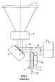
- FIG. 1is a block diagram illustrating the invention taught in U.S. Pat. No. 6,024,453 . It shows a color wheel 1 having filter segments 12 comprising wedges forming a disk which rotates about axis 10. Motor 2 acts on carrier 11, causing the color wheel to rotate and the filter segments to intercept light beam 6 from light source 5, as monitored by position sensor 3. As the color wheel rotates, the light passes through the filter segments in turn, projecting light of different colors along optical axis 60 in short bursts toward image generation device 7. The light reflects off of an image generation device 7, forming an image transmitted to projection lens 8, and then to a screen 9.
- Pat. No. 6,024,453describes the environment in which color wheels must operate.
- the wheelmust rotate on the order of thousands of revolutions per minute, and must tolerate high temperatures (on the order of 100°C) due to its proximity to light source 5.
- the position of filter segments 12, relative to each other and the axis or rotation,must be carefully maintained in order to balance the color wheel and achieve a long operational life of the device.
- the method of attaching the filter segments to the carrieris as follows: the plain color filter segments are bonded on the periphery of the circular carrier via adhesive bonding applied where the glass segment overlaps the carrier.
- the bonding areais confined to a small ring zone near the center of rotation.
- a balancing procedureis performed on the color wheel after fabrication, for example by selectively removing material from the carrier, forming recesses.
- the recessesmay be selectively filled with a material such as adhesive or cement.
- the color wheel fabrication procedure taught in this patentworks well, but the fabrication process requires many steps.
- the glass segmentsare aligned and bonded onto the carrier with a photo-reactive adhesive, which then requires a secondary cure in a heat oven to finish the adhesive, cure.
- the color ringis then attached to a motor with an adhesive such as epoxy, and this assembly is cured again in a heat oven.
- An object of the present inventionis to provide an improved fabrication technique for color wheels. This object is accomplished by utilizing a pressure sensitive adhesive (PSA) to attach the wedge-shaped glass filter segments to a huh during the ring build. Then a strong adhesive such as epoxy is used to adhere the filter segments to the color wheel motor turning surface. No photo-reaction or oven curing is required for the PSA filter segment/hub adhesion step. If an oven cure is required for the filter segment/motor adhesion step, it is at a lower temperature than the previously required filter segment/carrier adhesive process.
- PSApressure sensitive adhesive
- a method for forming a color wheel assemblycomprises the steps of attaching a plurality of attaching a plurality of color filter segments on a first side to a pressure sensitive adhesive element, adhering the pressure sensitive adhesive element to a hub balancing washer, and attaching the plurality of color filter segments on a second side through the use of an adhesive to a turning surface of a motor mounted on a motor base.
- a method for forming a color wheel assemblycomprises the step of forming a color ring by attaching a plurality of color filter segments on a first side to a pressure sensitive adhesive element and attaching the pressure sensitive adhesive element to a hub balancing washer.
- the pressure sensitive adhesive elementtemporarily aligns the plurality of color filter segments in an alignment.
- Another step in the methodis to attach the color ring on a second side of the plurality of color filter segments through the use of an adhesive to a turning surface of a motor mounted on a motor base. The adhesive between the color ring and the turning surface permanently bonds the color filter segments in the alignment.
- a method for operating a projection systemcomprises the step of providing a color ring formed by attaching a plurality of color filter segments on a first side to a pressure sensitive adhesive element and attaching the pressure sensitive adhesive element to a hub balancing washer.
- the pressure sensitive adhesive elementtemporarily aligns the plurality of color filter segments in an alignment.
- Another step in the methodis to provide a motor mounted on a motor base, where the motor includes a spindle and the color ring has a center space that receives the spindle.
- the color ringis attached on a second side of the plurality of color filter segments through the use of an adhesive to permanently bond the color filter segments in the alignment on a turning surface of the motor.
- Another step in the methodis to operate the motor at a speed to rotate the spindle and the color ring together.
- Figure 1shows a color wheel in use in a projection system.
- Figure 2is a side isometric diagram illustrating a first part of an improved color wheel fabrication technique of the present invention, the ring build.
- Figure 3is an isometric drawing showing a completed color ring.
- Figure 4is a side isometric diagram illustrating a second part of the improved color wheel fabrication technique of the present invention, the color wheel completion.
- Figure 5is a side isometric drawing sowing a completed color wheel assembly.
- Example embodiments that incorporate one or more aspects of the present inventionare described and illustrated in the drawings. These illustrated examples are not intended to be a limitation on the present invention. For example, one or more aspects of the present invention can be utilized in other embodiments and even other types of devices. Moreover, certain terminology is used herein for convenience only and is not to be taken as a limitation on the present invention. Still further, in the drawings, the same reference numerals are employed for designating the same elements.
- FIG. 2is a side isometric diagram illustrating a first part of the improved color wheel fabrication technique of the present invention.
- the first part of forming the color wheelis building a color ring assembly.
- the color filter segments 106are attached to a hub balancing washer 102 using a Pressure Sensitive Adhesive (PSA) element 104, which can be in the shape of a ring. It is appreciated that the pressure sensitive adhesive element can be formed from shapes other than a ring where the shapes have an opening in the center.
- the hub balancing washercan be configured for balancing the color ring.
- the color filter segments 106can be of a variety of shapes and sizes, as shown in FIG. 2 .
- the color filter segments 106can also be any type of float glass coated in at least one color (for example red, green, blue). There is no oven cure required for the ring build, nor is a photo-reactive cure required.
- the plurality of color filter segmentscan be attached on a first side, such as the top side, to the PSA element.
- the pressure sensitive adhesive element 104is used for temporarily fixing the color filter segments 106 to the hub balancing washer 102.
- the pressure sensitive adhesive element 104can temporarily align the color filter segments 106 in an alignment, such as the alignment shown in FIG. 2 .
- the alignmentcorresponds to the orientation of the individual filter segments relative to each other.
- the alignment of the color filter segments 106can be used during the rest of the fabrication process.
- the alignment of the color filter segments 106can provide a center space 112 that is configured for receiving a spindle of the motor 110.
- the PSA materialcan be semi-solid and can be easily stamped into the preferred ring-shape and applied with no flowing. Therefore, no cleanup or care is required for the.pressure sensitive adhesive element.
- the PSA element 104is sized to adhere the color filter segments 106 to the hub balancing washer 102 with no PSA extending outside the periphery of the hub onto the filter segments or into the center space 112 formed by the filter segments.
- the Pressure Sensitive Adhesivecan be selected from a number of commercially available products, such as a PSA product from 3M, double-coated tape, type 9500PC with adhesive 350.
- FIG. 3is an isometric drawing showing a completed color ring assembly 108, which can be formed from the temporary fixation of the plurality of color filter segments 106, the pressure sensitive adhesive element 104, and the hub balancing washer 102 as described with regards to FIG. 2 .
- the fabrication technique described for FIG. 2is useful for a number of different color ring/color wheel embodiments.
- the diameter of the color filter segments 106can be in a range of 25 mm to 60 mm or more and the color filter segments 106 can be comprised of float glass coated in at least one desired color.
- FIG. 4is a side isometric diagram illustrating a second part of the improved color wheel fabrication technique of the present invention, the color wheel assembly 122 completion.
- An epoxy adhesive 116can be applied between the color ring assembly 108 and a motor 110, shown in FIG. 4 .
- the motor 110may be a commercially available model, developed for hard drive applications such as the Tokyo Parts PVM9A12T10M1, for example.
- the motor 110includes a turning surface 118, such as a can, that is provided about a rotatable motor shaft or spindle 114. In one example method of operating a projection system, the motor 110 can be operated to rotate the spindle 114 and the color ring assembly 108 together.
- the turning surface 118rotates in response to activation of the spindle 114.
- the motor of the projection systemcan be operated at a spinning speed of between 7200 rpm to 14,400 rpm.
- the motor 110 and the turning surface 118can be mounted on a motor base 120.
- the motor base 120does not spin, and is used to mount the entire color wheel assembly 122 in place.
- the epoxy adhesive 116can be applied to attach a second side of the plurality of color filter segments 106, which are a part of the color ring assembly 108, to the motor 110.
- a bead of adhesive 116is applied in the shape of a ring on the turning surface 118 of the motor 110. In other examples, the bead of adhesive can be applied in other shapes on the turning surface 118 of the motor 110.
- the glass color filter segments 106 of the color ring assembly 108are pressed onto the adhesive 116. The pressing of the color ring assembly 108 onto the adhesive 116 forms the adhesive 116 into a flat film and adhering the color filter segments 106 directly to the turning surface 118.
- the epoxy adhesive 116 of FIG. 4can provide a permanent holding bond for the alignment of the color filter segments 106 during operation of the color wheel assembly 122.
- the adhesive 116can be a strong permanent adhesive, such as two-part adhesive epoxy, for example, Hysol 1C or 3M DP460.
- the adhesive 116provides a permanent bond that holds the color filter segments 106 in place, such as in the alignment formed during the assembly of the color ring 108. It is also possible that the adhesive 116 provides a permanent bond to hold the color filter segments 106 in a second alignment as the color filter segments 106 can move slightly from the original alignment.
- an oven curecan be required, but a curing temperature of approximately 85° and curing time of 30 to 45 minutes are lower than what was required in previous color wheel fabrication techniques.
- Choosing a different epoxy adhesive systemcan also potentially eliminate the need for an oven cure during the attachment of the color ring assembly 108 to the motor 110. Accordingly, the selection of an epoxy adhesive system that does not require an oven cure in either the formation of the color ring assembly 108 or the attachment of the color ring assembly 108 to the motor 110 can thus be provided.
- FIG. 5illustrates the completed color wheel assembly 122 formed by the assembly shown in FIG. 4 .
- the color filter segments 106 of the color ring assembly 108are now permanently affixed to the turning surface 118 by the adhesive 116.
- the hub balancing washer 102remains attached to the color ring assembly 108 via the PSA element 104, and may be used for balancing the color wheel assembly 122 in the conventional manner.
Landscapes
- Physics & Mathematics (AREA)
- General Physics & Mathematics (AREA)
- Astronomy & Astrophysics (AREA)
- Spectroscopy & Molecular Physics (AREA)
- Optics & Photonics (AREA)
- Engineering & Computer Science (AREA)
- Multimedia (AREA)
- Signal Processing (AREA)
- Optical Filters (AREA)
- Projection Apparatus (AREA)
- Mechanical Light Control Or Optical Switches (AREA)
- Dental Preparations (AREA)
Abstract
Description
- This invention relates to color wheel fabrication. More specifically, this invention relates to fabrication of color wheels for projection systems and the like using a simplified adhesive technique.
U.S. Pat. No. 6,024,453 is incorporated herein by reference.FIG. 1 (Prior Art) is a block diagram illustrating the invention taught inU.S. Pat. No. 6,024,453 . It shows a color wheel 1 havingfilter segments 12 comprising wedges forming a disk which rotates aboutaxis 10.Motor 2 acts oncarrier 11, causing the color wheel to rotate and the filter segments to interceptlight beam 6 fromlight source 5, as monitored byposition sensor 3. As the color wheel rotates, the light passes through the filter segments in turn, projecting light of different colors alongoptical axis 60 in short bursts towardimage generation device 7. The light reflects off of animage generation device 7, forming an image transmitted toprojection lens 8, and then to ascreen 9.- Pat. No.
6,024,453 describes the environment in which color wheels must operate. The wheel must rotate on the order of thousands of revolutions per minute, and must tolerate high temperatures (on the order of 100°C) due to its proximity tolight source 5. The position offilter segments 12, relative to each other and the axis or rotation, must be carefully maintained in order to balance the color wheel and achieve a long operational life of the device. - The method of attaching the filter segments to the carrier is as follows: the plain color filter segments are bonded on the periphery of the circular carrier via adhesive bonding applied where the glass segment overlaps the carrier. The bonding area is confined to a small ring zone near the center of rotation.
- A balancing procedure is performed on the color wheel after fabrication, for example by selectively removing material from the carrier, forming recesses. The recesses may be selectively filled with a material such as adhesive or cement.
- The color wheel fabrication procedure taught in this patent works well, but the fabrication process requires many steps. The glass segments are aligned and bonded onto the carrier with a photo-reactive adhesive, which then requires a secondary cure in a heat oven to finish the adhesive, cure. The color ring is then attached to a motor with an adhesive such as epoxy, and this assembly is cured again in a heat oven.
- Sometimes there are issues with curing the adhesive holding individual filter segments if the segments do not transmit the optimum wavelength for the photo-reactive adhesive. There is also an issue with stress induced by thermal expansion during the oven curing temperature of this adhesive.
- In
US2006/237357 A1 Jia Yan-Jun et al described a color wheel assembly which includes a carrier, a color filter assembly mounted on the carrier with the help of a packing ring and a press cover. The press cover and the packing ring are subsequently mounted on the color filter assembly after which bolts arc passed respectively through the through holes in the press cover, the packing ring and the central hole in the color filter assembly ad engaged threadedly to the carrier. The mounting of such a system is quite complicated and therefore expensive. - In
US5024453 Edlinger et al propose to adhere color filter segments to a carrier simply by using an adhesive to attach the color filter segments to a disk shaped carrier. This procedure is quite simple, however balancing has to be performed in a not well defined way as Edlinger et al just describe recesses or balancing bores. - A need remains in the art for an improved fabrication technique for color wheels.
- The following presents a simplified summary of the invention in order to provide a basic understanding of some example aspects of the invention. This summary is not an extensive overview of the invention. Moreover, this summary is not intended to identify critical elements of the invention nor delineate the scope of the invention. The sole purpose of the summary is to present some concepts of the invention in simplified form as a prelude to the more detailed description that is presented later.
- An object of the present invention is to provide an improved fabrication technique for color wheels. This object is accomplished by utilizing a pressure sensitive adhesive (PSA) to attach the wedge-shaped glass filter segments to a huh during the ring build. Then a strong adhesive such as epoxy is used to adhere the filter segments to the color wheel motor turning surface. No photo-reaction or oven curing is required for the PSA filter segment/hub adhesion step. If an oven cure is required for the filter segment/motor adhesion step, it is at a lower temperature than the previously required filter segment/carrier adhesive process.
- In accordance with one aspect of the present invention, a method is provided for forming a color wheel assembly is provided that comprises the steps of attaching a plurality of attaching a plurality of color filter segments on a first side to a pressure sensitive adhesive element, adhering the pressure sensitive adhesive element to a hub balancing washer, and attaching the plurality of color filter segments on a second side through the use of an adhesive to a turning surface of a motor mounted on a motor base.
- In accordance with another aspect of the present invention, a method is provided for forming a color wheel assembly comprises the step of forming a color ring by attaching a plurality of color filter segments on a first side to a pressure sensitive adhesive element and attaching the pressure sensitive adhesive element to a hub balancing washer. The pressure sensitive adhesive element temporarily aligns the plurality of color filter segments in an alignment. Another step in the method is to attach the color ring on a second side of the plurality of color filter segments through the use of an adhesive to a turning surface of a motor mounted on a motor base. The adhesive between the color ring and the turning surface permanently bonds the color filter segments in the alignment.
- In accordance with another aspect of the present invention, a method is provided for operating a projection system that comprises the step of providing a color ring formed by attaching a plurality of color filter segments on a first side to a pressure sensitive adhesive element and attaching the pressure sensitive adhesive element to a hub balancing washer. The pressure sensitive adhesive element temporarily aligns the plurality of color filter segments in an alignment. Another step in the method is to provide a motor mounted on a motor base, where the motor includes a spindle and the color ring has a center space that receives the spindle. The color ring is attached on a second side of the plurality of color filter segments through the use of an adhesive to permanently bond the color filter segments in the alignment on a turning surface of the motor. Another step in the method is to operate the motor at a speed to rotate the spindle and the color ring together.
- The foregoing and other aspects of the present invention will become apparent to those skilled in the art to which the present invention relates upon reading the following description with reference to the accompanying drawings, in which:
Figure 1 (Prior Art) shows a color wheel in use in a projection system.Figure 2 is a side isometric diagram illustrating a first part of an improved color wheel fabrication technique of the present invention, the ring build.Figure 3 is an isometric drawing showing a completed color ring.Figure 4 is a side isometric diagram illustrating a second part of the improved color wheel fabrication technique of the present invention, the color wheel completion.Figure 5 is a side isometric drawing sowing a completed color wheel assembly.- Example embodiments that incorporate one or more aspects of the present invention are described and illustrated in the drawings. These illustrated examples are not intended to be a limitation on the present invention. For example, one or more aspects of the present invention can be utilized in other embodiments and even other types of devices. Moreover, certain terminology is used herein for convenience only and is not to be taken as a limitation on the present invention. Still further, in the drawings, the same reference numerals are employed for designating the same elements.
- The following table shows the reference numbers and associated elements used in the below-referenced drawings and the description of these drawings.
Reference Number Element 102 Hub balancing washer 104 Pressure sensitive adhesive (PSA) ring 106 Color Filter segments 108 Color ring assembly 110 Motor 112 Center space formed by filter segments 114 Motor shaft or spindle 116 Adhesive (filter segment/motor) 118 Motor turning surface (can) 120 Motor base (non-turning) 122 Color wheel assembly FIG. 2 is a side isometric diagram illustrating a first part of the improved color wheel fabrication technique of the present invention. The first part of forming the color wheel is building a color ring assembly. Thecolor filter segments 106 are attached to ahub balancing washer 102 using a Pressure Sensitive Adhesive (PSA)element 104, which can be in the shape of a ring. It is appreciated that the pressure sensitive adhesive element can be formed from shapes other than a ring where the shapes have an opening in the center. The hub balancing washer can be configured for balancing the color ring. Thecolor filter segments 106 can be of a variety of shapes and sizes, as shown inFIG. 2 . Thecolor filter segments 106 can also be any type of float glass coated in at least one color (for example red, green, blue). There is no oven cure required for the ring build, nor is a photo-reactive cure required.- The plurality of color filter segments can be attached on a first side, such as the top side, to the PSA element. The pressure sensitive
adhesive element 104 is used for temporarily fixing thecolor filter segments 106 to thehub balancing washer 102. The pressure sensitiveadhesive element 104 can temporarily align thecolor filter segments 106 in an alignment, such as the alignment shown inFIG. 2 . The alignment corresponds to the orientation of the individual filter segments relative to each other. The alignment of thecolor filter segments 106 can be used during the rest of the fabrication process. The alignment of thecolor filter segments 106 can provide acenter space 112 that is configured for receiving a spindle of themotor 110. - The PSA material can be semi-solid and can be easily stamped into the preferred ring-shape and applied with no flowing. Therefore, no cleanup or care is required for the.pressure sensitive adhesive element. In the preferred embodiment, the
PSA element 104 is sized to adhere thecolor filter segments 106 to thehub balancing washer 102 with no PSA extending outside the periphery of the hub onto the filter segments or into thecenter space 112 formed by the filter segments. The Pressure Sensitive Adhesive can be selected from a number of commercially available products, such as a PSA product from 3M, double-coated tape, type 9500PC with adhesive 350. FIG. 3 is an isometric drawing showing a completedcolor ring assembly 108, which can be formed from the temporary fixation of the plurality ofcolor filter segments 106, the pressure sensitiveadhesive element 104, and thehub balancing washer 102 as described with regards toFIG. 2 . The fabrication technique described forFIG. 2 is useful for a number of different color ring/color wheel embodiments. For example, the diameter of thecolor filter segments 106 can be in a range of 25 mm to 60 mm or more and thecolor filter segments 106 can be comprised of float glass coated in at least one desired color.FIG. 4 is a side isometric diagram illustrating a second part of the improved color wheel fabrication technique of the present invention, thecolor wheel assembly 122 completion. Anepoxy adhesive 116 can be applied between thecolor ring assembly 108 and amotor 110, shown inFIG. 4 . Themotor 110 may be a commercially available model, developed for hard drive applications such as the Tokyo Parts PVM9A12T10M1, for example. Themotor 110 includes a turningsurface 118, such as a can, that is provided about a rotatable motor shaft orspindle 114. In one example method of operating a projection system, themotor 110 can be operated to rotate thespindle 114 and thecolor ring assembly 108 together. The turningsurface 118 rotates in response to activation of thespindle 114. The motor of the projection system can be operated at a spinning speed of between 7200 rpm to 14,400 rpm. Themotor 110 and the turningsurface 118 can be mounted on amotor base 120. Themotor base 120 does not spin, and is used to mount the entirecolor wheel assembly 122 in place.- The
epoxy adhesive 116 can be applied to attach a second side of the plurality ofcolor filter segments 106, which are a part of thecolor ring assembly 108, to themotor 110. A bead of adhesive 116, enough to coat the desired surface without excess, is applied in the shape of a ring on the turningsurface 118 of themotor 110. In other examples, the bead of adhesive can be applied in other shapes on the turningsurface 118 of themotor 110. The glasscolor filter segments 106 of thecolor ring assembly 108 are pressed onto the adhesive 116. The pressing of thecolor ring assembly 108 onto the adhesive 116 forms the adhesive 116 into a flat film and adhering thecolor filter segments 106 directly to theturning surface 118. Once thecolor ring assembly 108 is attached to themotor 110, a completecolor wheel assembly 122 is formed, as shown inFIG. 5 . - The
epoxy adhesive 116 ofFIG. 4 can provide a permanent holding bond for the alignment of thecolor filter segments 106 during operation of thecolor wheel assembly 122. The adhesive 116 can be a strong permanent adhesive, such as two-part adhesive epoxy, for example, Hysol 1C or 3M DP460. The adhesive 116 provides a permanent bond that holds thecolor filter segments 106 in place, such as in the alignment formed during the assembly of thecolor ring 108. It is also possible that the adhesive 116 provides a permanent bond to hold thecolor filter segments 106 in a second alignment as thecolor filter segments 106 can move slightly from the original alignment. In the example two-part epoxy, an oven cure can be required, but a curing temperature of approximately 85° and curing time of 30 to 45 minutes are lower than what was required in previous color wheel fabrication techniques. Choosing a different epoxy adhesive system can also potentially eliminate the need for an oven cure during the attachment of thecolor ring assembly 108 to themotor 110. Accordingly, the selection of an epoxy adhesive system that does not require an oven cure in either the formation of thecolor ring assembly 108 or the attachment of thecolor ring assembly 108 to themotor 110 can thus be provided. FIG. 5 illustrates the completedcolor wheel assembly 122 formed by the assembly shown inFIG. 4 . InFIG. 5 , thecolor filter segments 106 of thecolor ring assembly 108 are now permanently affixed to theturning surface 118 by the adhesive 116. Thehub balancing washer 102 remains attached to thecolor ring assembly 108 via thePSA element 104, and may be used for balancing thecolor wheel assembly 122 in the conventional manner.- The invention has been described with reference to the examples described above. Modifications and alterations will occur to others upon a reading and understanding of this specification. Examples incorporating one or more aspects of the invention are intended to include all such modifications and alterations insofar as they come within the scope of the appended claims.
Claims (21)
- A method of forming a color wheel assembly (122) comprising the steps of:attaching a plurality of color filter segments (106) on a second side through the use of an adhesive to a turning surface (118) of a motor (110) mounted on a motor base (120);characterized in thatthe method further comprises the steps ofattaching the plurality of color filter segments on a first side to a pressure sensitive adhesive element (104);adhering the pressure sensitive adhesive element to a hub balancing washer (102).
- The method of claim 1, wherein the pressure sensitive adhesive element is semi-solid.
- The method of claim 1, wherein the pressure sensitive adhesive element is a double-coated tape.
- The method or claim 1 wherein the pressure sensitive adhesive element does not require a photo-reaction or oven curing to attach the plurality of color filter segments to the hub balancing washer.
- The method of claim 1. wherein each filter segment is comprised of float glass coated in at least one color.
- The method of claim 1, wherein the adhesive is a two-part adhesive.
- The method of claim 1, wherein the adhesive is applied in the shape of a ring to the turning surface.
- The method of claim 1, further comprising the step of curing the adhesive at 85° for a time between 30 to 45 minutes.
- The method of claim 1 wherein the pressure sensitive adhesive element temporarily aligns the plurality of color filter segments in an alignment, and wherein the adhesive, between the color ring and the turning surface permanently bonds the color filter segments in the alignment.
- The method of claim 9, wherein the pressure sensitive adhesive element is semi-solid.
- The method of claim 9, wherein the pressure sensitive adhesive, element is a double-coated tape.
- The method of claim 9, wherein the pressure sensitive adhesive element does not require a photo-reaction or oven curing.
- The method of claim 9, wherein each filter segment is comprised of float glass coated in at least one color.
- The method of claim 9, wherein the adhesive is a two-part adhesive.
- The method of claim 9, wherein the adhesive is applied in the shape of a ring to the turning surface.
- The method of claim 9, further comprising the step of curing the adhesive at 85" for a time between 30 to 45 minutes.
- The method of claim 9, wherein the diameter of the alignment of the color filter segments is in a range of 25 mm to 60mm.
- A method of operating a projection system comprising the steps of:forming a color wheel assembly (122) according to the method of claim 1, the color filter segments forming a color ring (108); wherein the motor includes a spindle (114) and the color ring has a center space (112) that receives the spindle; and operating the motor at a speed to rotate the spindle and the color ring together.
- The method of claim 18, wherein the motor is operated at a speed between 7200 rpm to 14,400 rpm.
- The method of claim 18, wherein each filter segment is comprised of float glass coated in at least one color.
- The method of claim 18, wherein the adhesive is applied in the shape of a ring to the turning surface.
Applications Claiming Priority (2)
| Application Number | Priority Date | Filing Date | Title |
|---|---|---|---|
| US97558107P | 2007-09-27 | 2007-09-27 | |
| PCT/EP2008/007877WO2009040056A1 (en) | 2007-09-27 | 2008-09-19 | Color wheel fabrication |
Publications (2)
| Publication Number | Publication Date |
|---|---|
| EP2191317A1 EP2191317A1 (en) | 2010-06-02 |
| EP2191317B1true EP2191317B1 (en) | 2011-04-06 |
Family
ID=40070592
Family Applications (1)
| Application Number | Title | Priority Date | Filing Date |
|---|---|---|---|
| EP08802389AActiveEP2191317B1 (en) | 2007-09-27 | 2008-09-19 | Color wheel fabrication |
Country Status (8)
| Country | Link |
|---|---|
| US (1) | US7997738B2 (en) |
| EP (1) | EP2191317B1 (en) |
| JP (1) | JP5309374B2 (en) |
| CN (2) | CN101855581A (en) |
| AT (1) | ATE504853T1 (en) |
| DE (1) | DE602008006100D1 (en) |
| TW (1) | TWI461751B (en) |
| WO (1) | WO2009040056A1 (en) |
Families Citing this family (9)
| Publication number | Priority date | Publication date | Assignee | Title |
|---|---|---|---|---|
| CN101630050B (en)* | 2008-07-17 | 2011-03-30 | 鸿富锦精密工业(深圳)有限公司 | Color wheel and digital light processing projector with the color wheel |
| DE102011084961A1 (en)* | 2011-10-21 | 2013-04-25 | Osram Gmbh | Fluorescent wheel, method for producing a phosphor wheel and lighting arrangement |
| CN102854729B (en)* | 2012-02-26 | 2014-03-19 | 深圳市光峰光电技术有限公司 | Light-emitting device, light-emitting device assembly and related projection system |
| CN104566229B (en)* | 2013-10-15 | 2016-06-08 | 深圳市光峰光电技术有限公司 | Manufacturing method of wavelength conversion device |
| FR3024137B1 (en)* | 2014-07-24 | 2016-07-29 | Saint Gobain | METHOD FOR MANUFACTURING COMPLEX SHAPE GLASS SHEETS |
| KR20170113533A (en)* | 2015-02-03 | 2017-10-12 | 니폰 덴키 가라스 가부시키가이샤 | Wavelength conversion member and light emitting device using same |
| EP3438742A1 (en)* | 2016-03-31 | 2019-02-06 | Sony Corporation | Light source device, image display device, and optical unit |
| CN114488673B (en) | 2020-10-27 | 2023-08-08 | 中强光电股份有限公司 | wavelength conversion element |
| CN214846204U (en)* | 2021-06-24 | 2021-11-23 | 中强光电股份有限公司 | Wavelength conversion element and projection device |
Family Cites Families (14)
| Publication number | Priority date | Publication date | Assignee | Title |
|---|---|---|---|---|
| JPH07113684B2 (en)* | 1986-02-25 | 1995-12-06 | ソニー株式会社 | Optical filter device |
| US6024453A (en)* | 1997-04-29 | 2000-02-15 | Balzers Aktiengesellshaft | Method of rapidly producing color changes in an optical light path |
| DE10254135B3 (en)* | 2002-11-20 | 2004-06-09 | Hans-Werner Dehne | Plasma discharge device, for gas sterilizing, odor neutralizing and particle removal, has liquid metal and hardener mass between inner core electrode and glass barrier |
| TWI226942B (en)* | 2003-11-11 | 2005-01-21 | Asia Optical Co Inc | Filter set and color wheel with the filter set |
| TWI242684B (en)* | 2004-01-30 | 2005-11-01 | Asia Optical Co Inc | Color wheel capable of preventing filter from escape |
| US7234816B2 (en)* | 2004-02-03 | 2007-06-26 | 3M Innovative Properties Company | Polarizing beam splitter assembly adhesive |
| JP2006133661A (en)* | 2004-11-09 | 2006-05-25 | Minebea Co Ltd | Color wheel, its manufacturing method and its manufacturing tool |
| CN100397238C (en)* | 2004-11-18 | 2008-06-25 | 普立尔科技股份有限公司 | Color wheel and assembling method thereof |
| TWI265359B (en)* | 2004-12-10 | 2006-11-01 | Asia Optical Co Inc | Color wheel that can prevents filters from flying away and manufacturing method thereof |
| US7391569B2 (en)* | 2004-12-29 | 2008-06-24 | 3M Innovative Properties Company | Projection system including intrinsic polarizer |
| JP4831395B2 (en)* | 2005-02-10 | 2011-12-07 | ミネベア株式会社 | Color wheel and manufacturing method thereof |
| KR100691154B1 (en)* | 2005-03-16 | 2007-03-09 | 삼성전기주식회사 | Color wheel for md projection display |
| JP5265845B2 (en)* | 2005-04-15 | 2013-08-14 | スリーエム イノベイティブ プロパティズ カンパニー | Double-sided adhesive tape |
| TWI274953B (en)* | 2005-04-22 | 2007-03-01 | Asia Optical Co Inc | Wheel color set |
- 2008
- 2008-09-19EPEP08802389Apatent/EP2191317B1/enactiveActive
- 2008-09-19ATAT08802389Tpatent/ATE504853T1/ennot_activeIP Right Cessation
- 2008-09-19CNCN200880109382Apatent/CN101855581A/enactivePending
- 2008-09-19WOPCT/EP2008/007877patent/WO2009040056A1/enactiveApplication Filing
- 2008-09-19CNCN201410045410.8Apatent/CN103777302A/enactivePending
- 2008-09-19JPJP2010526199Apatent/JP5309374B2/ennot_activeExpired - Fee Related
- 2008-09-19DEDE602008006100Tpatent/DE602008006100D1/enactiveActive
- 2008-09-22USUS12/234,926patent/US7997738B2/enactiveActive
- 2008-09-25TWTW097136790Apatent/TWI461751B/ennot_activeIP Right Cessation
Also Published As
| Publication number | Publication date |
|---|---|
| WO2009040056A1 (en) | 2009-04-02 |
| JP2010540997A (en) | 2010-12-24 |
| CN101855581A (en) | 2010-10-06 |
| ATE504853T1 (en) | 2011-04-15 |
| EP2191317A1 (en) | 2010-06-02 |
| US7997738B2 (en) | 2011-08-16 |
| CN103777302A (en) | 2014-05-07 |
| US20090122273A1 (en) | 2009-05-14 |
| DE602008006100D1 (en) | 2011-05-19 |
| JP5309374B2 (en) | 2013-10-09 |
| TWI461751B (en) | 2014-11-21 |
| TW200921158A (en) | 2009-05-16 |
Similar Documents
| Publication | Publication Date | Title |
|---|---|---|
| EP2191317B1 (en) | Color wheel fabrication | |
| US6024453A (en) | Method of rapidly producing color changes in an optical light path | |
| US6715887B2 (en) | Color wheel module for image display device | |
| GB2312757A (en) | Color wheel for picture generation unit | |
| US7187509B2 (en) | Color wheel and manufacturing method of same | |
| JP4447670B2 (en) | Color wheel and image generation apparatus having the color wheel | |
| TWI422950B (en) | Color wheel | |
| JP2010540997A5 (en) | ||
| JP4223203B2 (en) | Rotating optical filter device | |
| US20080049346A1 (en) | Color wheel | |
| US20080180823A1 (en) | Color wheel | |
| US6999252B2 (en) | Color wheel having a limiting element for preventing radial displacement | |
| JP2006047836A (en) | Color wheel | |
| US6963457B1 (en) | Color wheel of segment type | |
| US7113353B2 (en) | Method of fixing color wheel to motor | |
| US7190536B2 (en) | Color filter disc and process of making the same | |
| US20060126199A1 (en) | Color wheel and its manufacturing method | |
| CN100487268C (en) | Vibration eliminating device and method for rotating disk | |
| TWI411865B (en) | Color wheel | |
| JPH05129729A (en) | Laser light source device | |
| TWI345674B (en) | Color wheel, manufacture apparatus and manufacture method for making same | |
| US7253977B2 (en) | Monolithic color wheel and process for fabrication of the same | |
| JP2003050362A (en) | Rotating optical filter device | |
| JP3094829U (en) | Color wheel module for video display equipment | |
| JP2008002969A (en) | Rotary encoder |
Legal Events
| Date | Code | Title | Description |
|---|---|---|---|
| PUAI | Public reference made under article 153(3) epc to a published international application that has entered the european phase | Free format text:ORIGINAL CODE: 0009012 | |
| 17P | Request for examination filed | Effective date:20100216 | |
| AK | Designated contracting states | Kind code of ref document:A1 Designated state(s):AT BE BG CH CY CZ DE DK EE ES FI FR GB GR HR HU IE IS IT LI LT LU LV MC MT NL NO PL PT RO SE SI SK TR | |
| AX | Request for extension of the european patent | Extension state:AL BA MK RS | |
| 17Q | First examination report despatched | Effective date:20100810 | |
| GRAP | Despatch of communication of intention to grant a patent | Free format text:ORIGINAL CODE: EPIDOSNIGR1 | |
| DAX | Request for extension of the european patent (deleted) | ||
| GRAS | Grant fee paid | Free format text:ORIGINAL CODE: EPIDOSNIGR3 | |
| GRAA | (expected) grant | Free format text:ORIGINAL CODE: 0009210 | |
| AK | Designated contracting states | Kind code of ref document:B1 Designated state(s):AT BE BG CH CY CZ DE DK EE ES FI FR GB GR HR HU IE IS IT LI LT LU LV MC MT NL NO PL PT RO SE SI SK TR | |
| REG | Reference to a national code | Ref country code:GB Ref legal event code:FG4D | |
| REG | Reference to a national code | Ref country code:CH Ref legal event code:EP | |
| REG | Reference to a national code | Ref country code:IE Ref legal event code:FG4D | |
| REF | Corresponds to: | Ref document number:602008006100 Country of ref document:DE Date of ref document:20110519 Kind code of ref document:P | |
| REG | Reference to a national code | Ref country code:DE Ref legal event code:R096 Ref document number:602008006100 Country of ref document:DE Effective date:20110519 | |
| REG | Reference to a national code | Ref country code:NL Ref legal event code:VDEP Effective date:20110406 | |
| PG25 | Lapsed in a contracting state [announced via postgrant information from national office to epo] | Ref country code:SI Free format text:LAPSE BECAUSE OF FAILURE TO SUBMIT A TRANSLATION OF THE DESCRIPTION OR TO PAY THE FEE WITHIN THE PRESCRIBED TIME-LIMIT Effective date:20110406 | |
| LTIE | Lt: invalidation of european patent or patent extension | Effective date:20110406 | |
| PG25 | Lapsed in a contracting state [announced via postgrant information from national office to epo] | Ref country code:NO Free format text:LAPSE BECAUSE OF FAILURE TO SUBMIT A TRANSLATION OF THE DESCRIPTION OR TO PAY THE FEE WITHIN THE PRESCRIBED TIME-LIMIT Effective date:20110706 Ref country code:HR Free format text:LAPSE BECAUSE OF FAILURE TO SUBMIT A TRANSLATION OF THE DESCRIPTION OR TO PAY THE FEE WITHIN THE PRESCRIBED TIME-LIMIT Effective date:20110406 Ref country code:LT Free format text:LAPSE BECAUSE OF FAILURE TO SUBMIT A TRANSLATION OF THE DESCRIPTION OR TO PAY THE FEE WITHIN THE PRESCRIBED TIME-LIMIT Effective date:20110406 Ref country code:SE Free format text:LAPSE BECAUSE OF FAILURE TO SUBMIT A TRANSLATION OF THE DESCRIPTION OR TO PAY THE FEE WITHIN THE PRESCRIBED TIME-LIMIT Effective date:20110406 Ref country code:PT Free format text:LAPSE BECAUSE OF FAILURE TO SUBMIT A TRANSLATION OF THE DESCRIPTION OR TO PAY THE FEE WITHIN THE PRESCRIBED TIME-LIMIT Effective date:20110808 | |
| PG25 | Lapsed in a contracting state [announced via postgrant information from national office to epo] | Ref country code:AT Free format text:LAPSE BECAUSE OF FAILURE TO SUBMIT A TRANSLATION OF THE DESCRIPTION OR TO PAY THE FEE WITHIN THE PRESCRIBED TIME-LIMIT Effective date:20110406 Ref country code:ES Free format text:LAPSE BECAUSE OF FAILURE TO SUBMIT A TRANSLATION OF THE DESCRIPTION OR TO PAY THE FEE WITHIN THE PRESCRIBED TIME-LIMIT Effective date:20110717 Ref country code:LV Free format text:LAPSE BECAUSE OF FAILURE TO SUBMIT A TRANSLATION OF THE DESCRIPTION OR TO PAY THE FEE WITHIN THE PRESCRIBED TIME-LIMIT Effective date:20110406 Ref country code:CY Free format text:LAPSE BECAUSE OF FAILURE TO SUBMIT A TRANSLATION OF THE DESCRIPTION OR TO PAY THE FEE WITHIN THE PRESCRIBED TIME-LIMIT Effective date:20110406 Ref country code:GR Free format text:LAPSE BECAUSE OF FAILURE TO SUBMIT A TRANSLATION OF THE DESCRIPTION OR TO PAY THE FEE WITHIN THE PRESCRIBED TIME-LIMIT Effective date:20110707 Ref country code:FI Free format text:LAPSE BECAUSE OF FAILURE TO SUBMIT A TRANSLATION OF THE DESCRIPTION OR TO PAY THE FEE WITHIN THE PRESCRIBED TIME-LIMIT Effective date:20110406 Ref country code:IS Free format text:LAPSE BECAUSE OF FAILURE TO SUBMIT A TRANSLATION OF THE DESCRIPTION OR TO PAY THE FEE WITHIN THE PRESCRIBED TIME-LIMIT Effective date:20110806 Ref country code:BE Free format text:LAPSE BECAUSE OF FAILURE TO SUBMIT A TRANSLATION OF THE DESCRIPTION OR TO PAY THE FEE WITHIN THE PRESCRIBED TIME-LIMIT Effective date:20110406 | |
| PG25 | Lapsed in a contracting state [announced via postgrant information from national office to epo] | Ref country code:NL Free format text:LAPSE BECAUSE OF FAILURE TO SUBMIT A TRANSLATION OF THE DESCRIPTION OR TO PAY THE FEE WITHIN THE PRESCRIBED TIME-LIMIT Effective date:20110406 | |
| PG25 | Lapsed in a contracting state [announced via postgrant information from national office to epo] | Ref country code:CZ Free format text:LAPSE BECAUSE OF FAILURE TO SUBMIT A TRANSLATION OF THE DESCRIPTION OR TO PAY THE FEE WITHIN THE PRESCRIBED TIME-LIMIT Effective date:20110406 Ref country code:EE Free format text:LAPSE BECAUSE OF FAILURE TO SUBMIT A TRANSLATION OF THE DESCRIPTION OR TO PAY THE FEE WITHIN THE PRESCRIBED TIME-LIMIT Effective date:20110406 | |
| PLBE | No opposition filed within time limit | Free format text:ORIGINAL CODE: 0009261 | |
| STAA | Information on the status of an ep patent application or granted ep patent | Free format text:STATUS: NO OPPOSITION FILED WITHIN TIME LIMIT | |
| PG25 | Lapsed in a contracting state [announced via postgrant information from national office to epo] | Ref country code:RO Free format text:LAPSE BECAUSE OF FAILURE TO SUBMIT A TRANSLATION OF THE DESCRIPTION OR TO PAY THE FEE WITHIN THE PRESCRIBED TIME-LIMIT Effective date:20110406 Ref country code:PL Free format text:LAPSE BECAUSE OF FAILURE TO SUBMIT A TRANSLATION OF THE DESCRIPTION OR TO PAY THE FEE WITHIN THE PRESCRIBED TIME-LIMIT Effective date:20110406 Ref country code:SK Free format text:LAPSE BECAUSE OF FAILURE TO SUBMIT A TRANSLATION OF THE DESCRIPTION OR TO PAY THE FEE WITHIN THE PRESCRIBED TIME-LIMIT Effective date:20110406 Ref country code:DK Free format text:LAPSE BECAUSE OF FAILURE TO SUBMIT A TRANSLATION OF THE DESCRIPTION OR TO PAY THE FEE WITHIN THE PRESCRIBED TIME-LIMIT Effective date:20110406 | |
| 26N | No opposition filed | Effective date:20120110 | |
| PG25 | Lapsed in a contracting state [announced via postgrant information from national office to epo] | Ref country code:MC Free format text:LAPSE BECAUSE OF NON-PAYMENT OF DUE FEES Effective date:20110930 | |
| REG | Reference to a national code | Ref country code:DE Ref legal event code:R097 Ref document number:602008006100 Country of ref document:DE Effective date:20120110 | |
| REG | Reference to a national code | Ref country code:IE Ref legal event code:MM4A | |
| PG25 | Lapsed in a contracting state [announced via postgrant information from national office to epo] | Ref country code:IE Free format text:LAPSE BECAUSE OF NON-PAYMENT OF DUE FEES Effective date:20110919 | |
| PG25 | Lapsed in a contracting state [announced via postgrant information from national office to epo] | Ref country code:MT Free format text:LAPSE BECAUSE OF FAILURE TO SUBMIT A TRANSLATION OF THE DESCRIPTION OR TO PAY THE FEE WITHIN THE PRESCRIBED TIME-LIMIT Effective date:20110406 | |
| PG25 | Lapsed in a contracting state [announced via postgrant information from national office to epo] | Ref country code:LU Free format text:LAPSE BECAUSE OF NON-PAYMENT OF DUE FEES Effective date:20110919 | |
| PG25 | Lapsed in a contracting state [announced via postgrant information from national office to epo] | Ref country code:BG Free format text:LAPSE BECAUSE OF FAILURE TO SUBMIT A TRANSLATION OF THE DESCRIPTION OR TO PAY THE FEE WITHIN THE PRESCRIBED TIME-LIMIT Effective date:20110706 | |
| PG25 | Lapsed in a contracting state [announced via postgrant information from national office to epo] | Ref country code:TR Free format text:LAPSE BECAUSE OF FAILURE TO SUBMIT A TRANSLATION OF THE DESCRIPTION OR TO PAY THE FEE WITHIN THE PRESCRIBED TIME-LIMIT Effective date:20110406 | |
| PG25 | Lapsed in a contracting state [announced via postgrant information from national office to epo] | Ref country code:HU Free format text:LAPSE BECAUSE OF FAILURE TO SUBMIT A TRANSLATION OF THE DESCRIPTION OR TO PAY THE FEE WITHIN THE PRESCRIBED TIME-LIMIT Effective date:20110406 | |
| PG25 | Lapsed in a contracting state [announced via postgrant information from national office to epo] | Ref country code:IT Free format text:LAPSE BECAUSE OF FAILURE TO SUBMIT A TRANSLATION OF THE DESCRIPTION OR TO PAY THE FEE WITHIN THE PRESCRIBED TIME-LIMIT Effective date:20110406 | |
| REG | Reference to a national code | Ref country code:FR Ref legal event code:PLFP Year of fee payment:9 | |
| REG | Reference to a national code | Ref country code:FR Ref legal event code:PLFP Year of fee payment:10 | |
| REG | Reference to a national code | Ref country code:FR Ref legal event code:PLFP Year of fee payment:11 | |
| PGFP | Annual fee paid to national office [announced via postgrant information from national office to epo] | Ref country code:GB Payment date:20230926 Year of fee payment:16 | |
| PGFP | Annual fee paid to national office [announced via postgrant information from national office to epo] | Ref country code:FR Payment date:20230926 Year of fee payment:16 Ref country code:DE Payment date:20230928 Year of fee payment:16 | |
| PGFP | Annual fee paid to national office [announced via postgrant information from national office to epo] | Ref country code:CH Payment date:20231001 Year of fee payment:16 | |
| REG | Reference to a national code | Ref country code:DE Ref legal event code:R119 Ref document number:602008006100 Country of ref document:DE | |
| REG | Reference to a national code | Ref country code:CH Ref legal event code:PL | |
| GBPC | Gb: european patent ceased through non-payment of renewal fee | Effective date:20240919 | |
| PG25 | Lapsed in a contracting state [announced via postgrant information from national office to epo] | Ref country code:DE Free format text:LAPSE BECAUSE OF NON-PAYMENT OF DUE FEES Effective date:20250401 | |
| PG25 | Lapsed in a contracting state [announced via postgrant information from national office to epo] | Ref country code:GB Free format text:LAPSE BECAUSE OF NON-PAYMENT OF DUE FEES Effective date:20240919 | |
| PG25 | Lapsed in a contracting state [announced via postgrant information from national office to epo] | Ref country code:FR Free format text:LAPSE BECAUSE OF NON-PAYMENT OF DUE FEES Effective date:20240930 | |
| PG25 | Lapsed in a contracting state [announced via postgrant information from national office to epo] | Ref country code:CH Free format text:LAPSE BECAUSE OF NON-PAYMENT OF DUE FEES Effective date:20240930 |