EP2190628B1 - Impact tool - Google Patents
Impact toolDownload PDFInfo
- Publication number
- EP2190628B1 EP2190628B1EP08832319.1AEP08832319AEP2190628B1EP 2190628 B1EP2190628 B1EP 2190628B1EP 08832319 AEP08832319 AEP 08832319AEP 2190628 B1EP2190628 B1EP 2190628B1
- Authority
- EP
- European Patent Office
- Prior art keywords
- impact
- rpm
- current
- time period
- motor
- Prior art date
- Legal status (The legal status is an assumption and is not a legal conclusion. Google has not performed a legal analysis and makes no representation as to the accuracy of the status listed.)
- Active
Links
Images


Classifications
- B—PERFORMING OPERATIONS; TRANSPORTING
- B25—HAND TOOLS; PORTABLE POWER-DRIVEN TOOLS; MANIPULATORS
- B25B—TOOLS OR BENCH DEVICES NOT OTHERWISE PROVIDED FOR, FOR FASTENING, CONNECTING, DISENGAGING OR HOLDING
- B25B21/00—Portable power-driven screw or nut setting or loosening tools; Attachments for drilling apparatus serving the same purpose
- B25B21/02—Portable power-driven screw or nut setting or loosening tools; Attachments for drilling apparatus serving the same purpose with means for imparting impact to screwdriver blade or nut socket
- B—PERFORMING OPERATIONS; TRANSPORTING
- B25—HAND TOOLS; PORTABLE POWER-DRIVEN TOOLS; MANIPULATORS
- B25B—TOOLS OR BENCH DEVICES NOT OTHERWISE PROVIDED FOR, FOR FASTENING, CONNECTING, DISENGAGING OR HOLDING
- B25B23/00—Details of, or accessories for, spanners, wrenches, screwdrivers
- B25B23/14—Arrangement of torque limiters or torque indicators in wrenches or screwdrivers
- B25B23/147—Arrangement of torque limiters or torque indicators in wrenches or screwdrivers specially adapted for electrically operated wrenches or screwdrivers
- B25B23/1475—Arrangement of torque limiters or torque indicators in wrenches or screwdrivers specially adapted for electrically operated wrenches or screwdrivers for impact wrenches or screwdrivers
Definitions
- the present inventionrelates to an impact tool such as an impact driver or an impact wrench.
- An impact tool disclosed in Japanese Patent Application Publication No. 2002-0 46078drives a rotational impact system, with a battery pack as a power source and with a motor as a driving source, so as to give a rotary motion to and an impact on an anvil.
- the impact toolthen intermittently transmits the rotational impact force to an end bit to tighten a screw, and the like.
- a direct-current motor having a brush and a commutatoris known as a motor which has been employed as the driving source.
- An impact tool including a motor having brushesis also disclosed in US 4,412,158 . This tool also includes a current limiter which reduces the motor speed if a preset current level is exceeded.
- a large impact reaction forceunavoidably occurs between an anvil and a hammer for hitting the anvil.
- the driving force of the brushless direct-current motoralso moves the hammer backward to a large extent. If the hammer moves backward to an excessive degree, a larger impact force is applied onto the system facing the hammer due to the collision therebetween, thereby breaking the system.
- the present inventionprovides an impact tool in accordance with claim 1, including a spindle, a motor, a rotational impact system, a current detecting unit, and a current control unit.
- the spindleextends in an axial direction thereof.
- the motorprovides the spindle with a rotational power in accordance with a motor current flowing therethrough.
- the rotational powerrotates the spindle about the axis at an rpm value.
- a rotational impact systemprovides an impact force as set forth in claim 1, thereby transmitting both the rotational power and the impact force to an end bit.
- the current detecting unitdetects a current value of the motor current.
- the current control unitreduces the current value if the current value detected by the current detecting unit exceeds a predetermined value.
- the current control unitreduces the current value during a first time period including a timing at which the rotational impact system provides the spindle with the impact force if the current value detected by the current detecting unit exceeds the predetermined value.
- the impact toolfurther includes an rpm detecting unit configured to detect the rpm value; and a minimum rpm determining unit configured to determine a minimum rpm from a plurality of rpm values detected, during a second time period, by the rpm detecting unit.
- the current control unitstarts to reduce the current value after a third time period has elapsed since the minimum rpm determining unit had determined the minimum rpm value.
- the impact toolfurther includes a maximum rpm determining unit configured to determine a maximum rpm from the plurality of rpm values detected, during the second time period, by the rpm detecting unit; and a period changing unit configured to change the first time period based on a period after the maximum rpm is detected before the minimum rpm is detected.
- a maximum rpm determining unitconfigured to determine a maximum rpm from the plurality of rpm values detected, during the second time period, by the rpm detecting unit
- a period changing unitconfigured to change the first time period based on a period after the maximum rpm is detected before the minimum rpm is detected.
- the intervalscan be corrected even when the impact by the spindle occurs at uneven intervals.
- the impact toolfurther includes an impact interval detecting unit configured to detect an impact interval at which the rotational impact system hits the end bit based on the period after the maximum rpm is detected before the minimum rpm is detected.
- the period changing unitchanges the first time period so that the first time period becomes longer than a reference time period, if the impact interval detected by the impact interval detecting unit is longer than a reference interval.
- the period changing unitchanges the first time period so that the first time period becomes shorter than the reference time period, if the impact interval detected by the impact interval detecting unit is shorter than the reference interval.
- the intervalscan be corrected reliably even when the impact by the spindle occurs at uneven intervals.
- the current control unitreduces the current value if the current detecting unit detects the current value exceeding the predetermined value a predetermined number of times during a fourth time period.
- the current control unitmaintains the current value if the current detecting unit fails to detect the current value exceeding the predetermined value during a fifth time period.
- the motoris a brushless direct-current motor.
- the impact toolcan tighten a screw, a bolt, or the like, into a workpiece more powerfully.
- the impact by the spindleis prevented from being excessive, thereby preventing the spindle from moving backward to an excessive degree to crash into the opposite wall.
- Fig. 1shows a whole configuration of an electric tool, in which the present invention is applied to a cordless impact driver.
- Figs. 2illustrate an operation of a rotational impact system.
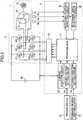
- Fig. 3is a block diagram showing a configuration of a motor driving unit of the electric tool which includes a brushless direct-current motor.
- the impact driver 100includes a tool body which has a main body housing 6 extending from one end thereof (right in the figure) to the other end (left in the figure), in the same direction (horizontal direction) as the rotating shaft of a brushless direct-current motor 1 to be described later (hereinafter, referred to as a "motor 1 "); and a handle housing 7 projecting downward from the main body housing 6.
- An end bit holder 8is provided at the other end of the main body housing 6.
- a driver bit(end bit) is detachably mounted to the end bit holder 8 so that a screw is tightened into a workpiece in the use of the rotational impact force applied from the tool body.
- a bolt-tightening bitcan be mounted as an end bit.
- a motor 1is mounted as a driving source.
- the end bit(not shown) is detachably mounted to the end bit holder 8 for delivering rotational impact force.
- a circuit board having an inverter 2 for driving the motor 1is mounted on the side of the one end of the main body housing 6, a circuit board having an inverter 2 for driving the motor 1, is mounted.
- a power transmission system (speed reduction system) 9for transmitting rotational power in the rotating shaft direction of the motor 1; a rotational impact system 10 for producing the rotational impact force; and an anvil 13 for transmitting the rotational impact force of the rotational impact system 10 to the end bit.
- a battery pack case 4which holds a battery pack 4a is detachably mounted as a power source of the motor 1.
- a circuit board having a control circuit section 3 for controlling the inverter 2 of the motor 1extends in a direction across the figure.
- a trigger switch 15is provided at the top end of the handle housing 7. The trigger switch 15 protrudes forward from the handle housing 7, in an urged state by a spring. As will be described later, the trigger switch 15 is depressed into the handle housing 7 against spring tension, thereby starting the motor 1. The rpm of the motor 1 is controlled by adjusting the amount of pressing the trigger switch 15.
- the battery pack 4ais electrically connected so that power is supplied to the trigger switch 15 and the control circuit (circuit board) section 3, as well as to the inverter section 2 at the same time.
- the rotational power from the rotary output shaft of the motor 1is transmitted to a spindle 11 included in the rotational impact system 10, through the power transmission system 9 engaging with the gear teeth of the rotary output shaft.
- the power transmission system 9includes a pinion gear (sun gear) 9a, and two planet gears 9b engaging with the pinion gear9a. These gears are located in an inner cover (not shown) within the main body housing 6.
- the power transmission system 9transmits the rotational power whose speed is reduced relative to that of the brushless direct-current motor 1, to the spindle 11.
- the rotational impact system 10includes the spindle 11 to which rotational power is transmitted through the power transmission system 9; a hammer 12 attached to the spindle 11, engaging with the spindle 11 movably in the rotating shaft direction, for producing rotational impact force; and an anvil 13 rotated by the rotational impact force produced by the hammer 12, having the end bit holder 8.
- the hammer 12has two hammer projections (percussors) 12a.
- the anvil 13has two anvil projections 13a.
- the hammer projections 12a and the anvil projections 13aare symmetrically arranged at two positions on a plane of rotation, in a manner such that each hammer projection 12a and its corresponding anvil projection 13a engages with each other in the rotating direction.
- the engagement between each projection pair of 12a and 13atransmits rotational impact force.
- the hammer 12is a ring-like frame surrounding the spindle 11 so as to be slidably in contact with the spindle 11 in the shaft direction, and is in an urged state by the spring 14 forward in the shaft direction.
- On the inner face of the hammer 12an inverted V-shaped (generally triangle) cam groove 12b is formed.
- a V-shaped cam groove 11ais formed in the shaft direction.
- a ball (steel ball) 17is inserted between the cam groove 11a and the cam groove 12b formed on the inner face of the hammer 12 so that the hammer 12 through the ball.
- Fig. 2shows the relation between a schematic operation of the rotational impact system 10 and a motor rpm, in which (A) shows a state that the hammer 12 moves backward and has left the projections 13a of the anvil 13; (B) shows a state that the hammer 12 rotatingly moves toward the projections 13a of the anvil 13, urged by a not shown spring, from the backward position; and (C) shows a state immediately before the hammer 12 goes into engagement between the projections 12a of the hammer 12 and the projections 13a of the anvil 13 in order to give a rotational impact force to projections 13a of the anvil 13 by the tension of the spring.
- the impact torqueis transmitted to the driver bit attached to the end bit holder 8 of the anvil 13.
- the driver bitthen transmits the impact torque to the clamping screw, thereby tightening the screw into the workpiece or clamping the workpiece.
- the motor 1is a three-phase brushless direct-current motor.
- the motor 1includes an inner rotor 1b having a permanent magnet including one pair of north and south poles, embedded therein; three rotational position detectors (hall ICs) 5a, 5b, and 5c arranged at intervals of 60°, for detecting the rotational position of the magnet rotor 1b; and an armature winding 1d having three-phase windings U, V, and W of a star-connected stator 1c, controlled to become a current application section of an electric angle of 120° based on position detection signals from the rotational position detectors 5a, 5b, and 5c.
- the motor 1detects the position of the rotor 1b by using the hall ICs in an electromagnetic coupling manner.
- the rotor positioncan also be detected sensorlessly by extracting the induced electromotive voltage (counter electromotive force) of the stator winding 1d as logical signals, through a filter.
- the inverter circuit section (power converter) 2includes six, three-phase bridge-connected FETs (hereinafter, referred to as "transistors") Q1-Q6; and a flywheel diode (not shown).
- Each gate of the bridge-connected transistors Q1-Q6is connected to a control signal output circuit 37.
- Either source or drain of each of the six transistors Q1-Q6is connected to one of the star-connected armature windings U, V, and W.
- a switching element driving signalis inputted from the control signal output circuit 37 so that the six transistors Q1-Q6 perform a switching operation.
- the control circuit section 3includes an operation unit 31, a current detection circuit 32, an applied voltage setting circuit 33, a rotating direction setting circuit 34, a rotational position detection circuit 35, a rotational speed detection circuit 36, and a control signal output circuit 37.
- the operation unit 31, although not shown,has a microcomputer which includes a CPU for outputting driving signals based on processing programs and data; a ROM for storing programs and control data corresponding to flowcharts to be described later; a RAM for storing data temporarily; and a timer.
- the current detection circuit 32detects the motor current flowing through the motor 1. The detected current is inputted to the operation unit 31.
- the applied voltage setting circuit 33sets the voltage to be applied to the motor 1, specifically, the duty ratio of a PWM signal, in response to the amount of the pressure applied by the trigger switch 15.
- the rotating direction setting circuit 11sets the rotating direction of the motor 1 by detecting an operation of rotating the motor in either forward or reverse direction performed through a forward-reverse switching lever 16.
- the rotational position detection circuit 35detects the positions of the rotor 1b and the stator 1c, relative to the armature windings U, V, and W, based on signals outputted from the three rotational position detectors 5a, 5b, and 5c.
- the rotational speed detection circuit 36detects the rpm of the motor, based on the number of detection signals from the rotational position detection circuit 35, counted per unit time.
- the control signal output circuit 37transmits PWM signals to the transistors Q1-Q6 positioned on the power source side, based on the output from the operation unit 31.
- the pulse width of each PWM signalis controlled so that power to be supplied to each of the armature windings U, V, and W is adjusted, thereby controlling the rpm of the motor 1 in the preset rotating direction.
- Fig. 4is a time chart showing the relation between an impact torque T, a motor current I, and a motor rpm N.
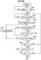
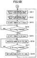
- Fig. 5A and Fig. 5Bare flowcharts showing the control of reducing the rpm of the motor 1 before and after the impact by the hammer 12.
- the load applied to the motor 1reaches a maximum. As shown in Fig. 4 , the rpm N of the motor 1 reaches a minimum ((A)) in the result. On the other hand, since the load applied to the motor 1 reaches a maximum, the motor current I reaches a maximum ((B)). After that, as the hammer 12 gets on the anvil projections 13a of the anvil 13, the load applied in the rotating direction of the motor 1 is reduced. The hammer 12 then gets over the anvil projections 13a of the anvil 13, to go out of the engagement with the anvil 13 ((A) and (B) of Fig. 2 ).
- the load applied to the motor 1reaches a minimum, and the rpm N of the motor 1 reaches a maximum ((C)).
- the motor current Ireaches a minimum ((D)).
- the hammer 12performs an impact motion ((E)).
- a motor having a large drive powersuch as a brushless motor
- the impact by the hammeris too strong.
- the hammergets on the anvil projections, the hammer moves backward to an excessive degree. This may cause the hammer to crash into the opposite wall, thereby breaking the wall.
- the rpm of the motor 1is reduced before and after the impact by the hammer 12 in this mode.
- the CPUdetermines whether or not the PWM duty of the motor control is 100%. This is because the hammer 12 usually moves backward to an excessive degree when the trigger switch 15 is depressed to the fullest extent, specifically, when the PWM duty cycle is 100%.
- the CPUcontinues to determine whether or not the PWM duty cycle is 100%. If the PWM duty is 100% (S501: YES), the CPU determines whether or not the motor current I is 35A or larger in S502. In this mode, a threshold value is set to 35A, which may cause the hammer 12 to move backward to an excessive degree. However, another value can be employed as the threshold value.
- the CPUdetermines whether or not the motor current I is 35A or larger. If the motor current I is 35A or larger (S502: YES), the CPU starts the timer for a time period Ta (10 msec) in S503 (see Fig. 4 ). In S504, the CPU determines again whether or not the motor current I is 35A or larger.
- the CPUcounts up a CNT 1 in S505. In S506, the CPU determines whether or not the time period Ta (10 msec) has passed. If the motor current I is smaller than 35A (S504: NO), the CPU determine whether or not the time period Ta (10 msec) has passed, without counting up the CNT 1 in S506. In this manner, the number of times the motor current I is equal to the threshold value 35A or larger, is counted, detected within a predetermined period of time (10 msec in this mode).
- the CPUreturns to S502. In S502, the CPU again determines whether or not the motor current I is 35A or larger. If the number counted up by the CNT 1 is larger than 5 (S508: YES), the CPU counts up a CNT 2 in S509. In S510, the CPU determines whether or not the number counted up by the CNT 2 is larger than 5. If the number counted up by the CNT 2 is 5 or smaller (S510: NO), the CPU returns to S502. In S502, the CPU again determines whether or not the motor current I is 35A or larger. After the determination five times in S508, that the motor current I detected in S503 to S507 becomes equal to or exceeds the threshold value 35A more than five times in total, the CPU starts the control of reducing the rpm of the motor 1.
- the CPUdecides the maximum value Nmax for the motor rpm N in S511 (see Figs. 4 ). In this mode, the CPU detects the motor rpm N per 1 msec. If a detected result is larger than the previous detected result, the CPU updates the maximum value. The CPU employs the updated value after four detection operations as the maximum value Nmax. As a result, the CPU detects the moment when the impact by the hammer 12 occurs.
- the CPUdecides a minimum value Nmin for the motor rpm N (see Figs. 4 ). In this mode, the CPU detects the motor rpm N per 1 msec. If a detected result is smaller than the previous detected result, the CPU updates the minimum value. The CPU employs the updated minimum value after four detection operations as a minimum value Nmin. As a result, the CPU detects the moment when the hammer 12 combines with the anvil projections 13a, specifically, the moment immediately before the hammer 12 gets on the anvil projections 13a.
- the CPUstarts the timer for a time period Tb (7 msec).
- the CPUdetermines whether or not the time period Tb (7 msec) has passed (see Figs. 4 ). If the time period Tb (7 msec) has not passed yet (S514: NO), the CPU continues to determine whether or not the time period Tb (7 msec) has passed.
- the time period Tb (7 msec)is not limited to 7 msec as long as the time period Tb is shorter than the time period after the moment when the hammer 12 engages with the anvil projections 13a, until the moment the impact by the hammer 12 occurs.
- the motor 1is driven with a PWM duty cycle of 100% until the moment a little before the impact by the hammer 12 occurs.
- the CPUstarts the timer for a time period Tc (6 msec) in S515.
- the CPUreduces the PWM duty cycle to 70% (see Fig. 4 ).
- the time period Tc (6 msec)is not limited to 6 msec as long as the time period Tc includes the moment when the impact by the hammer 12.
- the motor 1is driven with a PWM duty cycle of 70% before and after the moment when the impact by the hammer 12 occurs.
- the CPUdetermine whether or not the time period Tc (6 msec) has passed in S517 (see Fig. 4 ). If the time period Tc (6 msec) has not passed yet (S517: NO), the CPU continues to determine whether or not the time period Tc (6 msec) has passed. If the time period Tc (6 msec) has passed (S517: YES), the CPU returns the PWM duty cycle to 100% in S518.
- This configurationreduces the PWM duty cycle of the motor control, specifically, reduces the rpm of the motor 1, before and after the moment when the impact by the hammer 12 occurs. As a result, the configuration prevents the impact by the hammer 12 from being excessive, thereby preventing the hammer 12 from moving backward to an excessive degree to crash into the opposite wall. Further, since the PWM duty cycle is reduced when the number at which the current value exceeds a predetermined value is equal to or greater than a predetermined number, the excessive impact by the spindle can be prevented reliably from occurring. Further, since the PWM duty cycle is reduced after the minimum value of the motor rpm is detected, the time at which the impact occurs can be detected reliably.
- FIGs. 6 , 7A and 7Ba description is given for the control of an impact driver 100 according to a second mode of the present invention.
- Figs. 6are time charts showing the relation between an impact torque T, a motor current I, and a motor rpm N.
- Figs. 7A and 7Bare flowcharts showing the control of reducing the rpm of the motor 1 before and after the impact by the hammer 12.
- the steps which are the same as in the flowcharts of Figs. 5A and 5Bhave the same reference numbers. A description is given only for different steps here.
- the CPUstarts the timer for a time period Tz (300 msec) in S701 (see Figs. 6 ). After that, the CPU determines whether or not the time period Tz (300 msec) has passed in S702. If the time period Tz (300 msec) has not passed yet (S702: NO), the CPU proceeds to S502 to perform the control described in Figs. 5A and 5B . If the CPU determines that the number counted up by the CNT 2 is 5 or smaller in S510, the CPU returns to S702 to determine whether or not the time period Tz (300 msec) has passed.
- the CPUdoes not start the control of reducing the rpm of the motor 1 within a predetermined period of time (300 msec in this mode)
- the CPUdoes not perform the control of reducing the rpm of the motor 1 later in the process, either.
- a driveris employed as the end bit
- a screwis to be tightened into a wooden board or the like. Therefore, if the rpm of the motor 1 is reduced during the screwing operation, the screw is likely not to reach the right position therefor.
- the CPUdoes not start the control of reducing the rpm of the motor 1 within the predetermined period of time, the CPU does not perform the control of reducing the rpm of the motor 1 later in the process, either. As a result, a screw is securely tightened in a wooden board or the like.
- FIG. 8are time charts showing the relation between an impact torque T, a motor current I, and a motor rpm N.
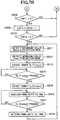
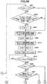
- Fig. 9A to Fig. 9Care flowcharts showing the control of reducing the rpm of the motor 1 before and after the impact by the hammer 12.
- the steps which are the same as in the flowcharts of Figs. 7A and 7Bhave the same reference numbers. A description is given only for different steps here.
- the CPUdetermines whether or not a Tc flag meaning that the time intervals of the impact by the hammer 12 are longer and shorter alternatively, as shown in Fig. 8A is zero in S901. If the Tc flag is zero (S901: YES), the CPU determines whether or not Td_old4 ⁇ Td_old3, Td_old3 > Td_old2, Td_old2 ⁇ Td_old1, and Td_old1 ⁇ Td at the same time in S902. In this case, the Td_old4, the Td_old3, the Td_old2, and the Td_old1 mean Tds one to four cycles before, respectively. The term Td is described later.
- Td_old4⁇ Td_old3, Td_old3 > Td_old2, Td_old2 ⁇ Td_old1, and Td_old1 ⁇ Td at the same time (S902: YES)
- the CPUsets the Tc flag to one in S904. After that, the CPU decides the maximum value Nmax for the motor rpm N in S511. If NO in S901 or S902, the CPU proceeds straight to S511 to decide a maximum value Nmax for the motor rpm N.
- Td_old4⁇ Td_old3, Td_old3 > Td_old2, Td_old2 ⁇ Td_old1, and Td_old1 ⁇ Td at the same time in a state that the Tc flag has been originally set to zero, the CPU sets the Tc flag to one.
- the CPUAfter deciding the maximum value Nmax for the motor rpm N in S511, the CPU starts the timer in S904. The CPU then decides a minimum value Nmin for the motor rpm N in S512. While deciding the minimum value Nmin for the motor rpm N, the CPU stops the timer from counting, and stores the counted value Td in S905. Specifically, the counted value Td means the period of time lapsed after the maximum value Nmax of the motor rpm N until the minimum value Nmin thereof. The Td thus stored is used for making the determination in S902.
- the CPUdetermines whether or not the Tc flag is one in S906. If the Tc flag is one (S906: YES), the CPU determines whether or not the previous value of the Tc is 4 msec in S907. If the previous value of the Tc is 4 msec (S907: YES), the CPU sets the time period Tc to 9 msec in S908, and then starts the timer in S911. On the other hand, if the previous value of the Tc is not 4 msec (S907: NO), the CPU sets the time period Tc to 4 msec in S909, and then starts the timer in S911.
- the CPUsets the time period Tc to 6 msec in S910, and then starts the timer in S911. In S912, the CPU reduces the PWM duty cycle to 70% at the same time as the timer starts in S911. After that, in S913, the CPU determines whether or not the time period Tc has passed.
- the CPUcontinues to determine whether or not the time period Tc has passed. If the time period Tc has passed (S913: YES), the CPU returns the PWM duty cycle to 100% in S914. In S915, the CPU determines whether or not a time period Tx has passed. If the time period Tx has not passed yet (S915: NO), the CPU returns to S901 to determine again whether or not the Tc flag is zero. If the time period Tx has passed (S915: YES), the CPU sets the Tc flag to zero in S916, then return to S901.
- the Td subsequent to the past Tdis predicted.
- the subsequent Tdis controlled to have even impact intervals. Therefore, even when the impact by the hammer 12 occurs at uneven intervals, the intervals can be corrected. This configuration prevents the impact by the hammer 12 from being excessive, thereby preventing the hammer 12 from moving backward to an excessive degree to crash into the opposite wall.
- Fig. 10is a time chart showing the relation between a motor current Ih under high load, a motor current I1 under low load, and a threshold current Ith.
- Fig. 11is a flowchart showing the control of reducing the motor current I when the motor current I exceeds the threshold current Ith. In this mode, the motor current I is reduced when the motor current I exceeds the threshold current Ith, like the motor current 1h under high load shown in Fig. 10 .
- the CPUdetermines whether or not the PWM duty cycle of the motor control is 100%. This is because the hammer 12 usually moves backward to an excessive degree when the trigger switch 15 is depressed to the fullest extent, specifically, when the PWM duty cycle is 100%.
- the CPUcontinues to determine whether or not the PWM duty cycle is 100%. If the PWM duty cycle is 100% (S1101: YES), the CPU determines whether or not the motor current I is 35A or larger in S1102. In this mode, the threshold current Ith is set to 35A, which may cause the hammer 12 to move backward to an excessive degree. However, another value can be employed as the threshold current Ith.
- the CPUcontinues to determine whether or not the motor current I is 35A or larger. If the motor current I is 35A or larger (S1102: YES), the CPU reduces the PWM duty cycle to 85% in S1103. As a result, the motor 1 is driven with a PWM duty cycle of 85%.
- the CPUAfter a time interval (3 msec) as a sampling time for controlling the operation unit 31 (S1104), the CPU increases the PWM duty cycle by 3% in S1105. In S1106, the CPU determine whether or not the PWM duty cycle is 100% or larger. Although the PWM duty cycle never exceeds 100% in practice, the CPU determine whether or not the PWM duty cycle is 100% or larger on calculation in the operation unit 31.
- the CPUreturns to S1104. After the time interval, the CPU increases the PWM duty cycle by 3% again in S1105. If the PWM duty cycle is 100% or larger (S1106: NO), this means that the PWM duty cycle has been set to 100%. The CPU returns to S1102 to determine again whether or not the motor current I is 35A or larger.
- An impact tool of the present inventioncan be used to tighten a screw, a bolt, or the like, in a workplace.
Landscapes
- Engineering & Computer Science (AREA)
- Mechanical Engineering (AREA)
- Portable Power Tools In General (AREA)
Description
- The present invention relates to an impact tool such as an impact driver or an impact wrench.
- An impact tool disclosed in
Japanese Patent Application Publication No. 2002-0 46078 US 4,412,158 . This tool also includes a current limiter which reduces the motor speed if a preset current level is exceeded. On the other hand, several attempts to employ a brushless direct-current motor instead of the direct-current motor, is also made. Since brushless direct-current motor is more excellent in torque characteristics than the direct-current motor with brush, the impact tool that employs the brushless direct-current motor can tighten a screw, a bolt, or the like, into a workpiece more powerfully. - However, in order to tighten a member of hard material such as a bolt or a nut, a large impact reaction force unavoidably occurs between an anvil and a hammer for hitting the anvil. In addition to the impact reaction force, the driving force of the brushless direct-current motor also moves the hammer backward to a large extent. If the hammer moves backward to an excessive degree, a larger impact force is applied onto the system facing the hammer due to the collision therebetween, thereby breaking the system.
- In view of the foregoing, it is an object of the present invention to provide an impact tool which facilitates a tightening operation with a large torque, as well as which prevents a system facing a hammer from breaking when a rotational impact force occurs.
- In order to attain the above and other objects, the present invention provides an impact tool in accordance with
claim 1, including a spindle, a motor, a rotational impact system, a current detecting unit, and a current control unit. The spindle extends in an axial direction thereof. The motor provides the spindle with a rotational power in accordance with a motor current flowing therethrough. The rotational power rotates the spindle about the axis at an rpm value. A rotational impact system provides an impact force as set forth inclaim 1, thereby transmitting both the rotational power and the impact force to an end bit. The current detecting unit detects a current value of the motor current. The current control unit reduces the current value if the current value detected by the current detecting unit exceeds a predetermined value. - In this configuration, the impact by the spindle can be prevented from being excessive.
- The current control unit reduces the current value during a first time period including a timing at which the rotational impact system provides the spindle with the impact force if the current value detected by the current detecting unit exceeds the predetermined value.
- In this configuration, the impact by the spindle can be effectively prevented from being excessive.
- Preferably, the impact tool further includes an rpm detecting unit configured to detect the rpm value; and a minimum rpm determining unit configured to determine a minimum rpm from a plurality of rpm values detected, during a second time period, by the rpm detecting unit. The current control unit starts to reduce the current value after a third time period has elapsed since the minimum rpm determining unit had determined the minimum rpm value.
- In this configuration, the time at which the impact occurs can be detected reliably.
- Preferably, the impact tool further includes a maximum rpm determining unit configured to determine a maximum rpm from the plurality of rpm values detected, during the second time period, by the rpm detecting unit; and a period changing unit configured to change the first time period based on a period after the maximum rpm is detected before the minimum rpm is detected.
- In this configuration, the intervals can be corrected even when the impact by the spindle occurs at uneven intervals.
- Preferably, the impact tool further includes an impact interval detecting unit configured to detect an impact interval at which the rotational impact system hits the end bit based on the period after the maximum rpm is detected before the minimum rpm is detected. The period changing unit changes the first time period so that the first time period becomes longer than a reference time period, if the impact interval detected by the impact interval detecting unit is longer than a reference interval. The period changing unit changes the first time period so that the first time period becomes shorter than the reference time period, if the impact interval detected by the impact interval detecting unit is shorter than the reference interval.
- In this configuration, the intervals can be corrected reliably even when the impact by the spindle occurs at uneven intervals.
- Preferably, the current control unit reduces the current value if the current detecting unit detects the current value exceeding the predetermined value a predetermined number of times during a fourth time period.
- In this configuration, the excessive impact by the spindle can be prevented reliably from occurring.
- Preferably, the current control unit maintains the current value if the current detecting unit fails to detect the current value exceeding the predetermined value during a fifth time period.
- In this configuration, the current value is not reduced when it is not desirable to reduce the current value. Therefore, a screw or the like can be securely tightened in a wooden board or the like
- Preferably, the motor is a brushless direct-current motor.
- In this configuration, the impact tool can tighten a screw, a bolt, or the like, into a workpiece more powerfully.
- With the invention described above, the impact by the spindle is prevented from being excessive, thereby preventing the spindle from moving backward to an excessive degree to crash into the opposite wall.
Fig. 1 shows a whole configuration of an electric tool according to embodiments of the present invention;Fig. 2 schematically illustrates the relation between an operation of a rotational impact system included in the electric tool shown inFig. 1 and a motor rpm;Fig. 3 is a functional block diagram showing a motor driving control system of the electric tool shown inFig. 1 ;Fig. 4 is a time chart showing various characteristics when a drive control according to a first embodiment of the present invention is performed;Fig. 5A is a flowchart illustrating the drive control according to the first embodiment of the present invention;Fig. 5B is a flowchart to be continued to the flowchart shown asFig. 5A ;Fig. 6 is a time chart showing various characteristics when a drive control according to a second embodiment of the present invention is performed;Fig. 7A is a flowchart illustrating the drive control according to the second embodiment of the present invention;Fig. 7B is a flowchart to be continued to the flowchart shown asFig. 7A ;Fig. 8 is a time chart showing various characteristics when a drive control according to a third embodiment of the present invention;Fig. 9A is a flowchart illustrating the drive control according to the third embodiment of the present invention;Fig. 9B is a flowchart to be continued to the flowchart shown asFig. 9A ;Fig. 9C is a flowchart to be continued to the flowchart shown asFig. 9B ;Fig. 10 is a time chart showing the relation between a motor current Ih under high load, a motor current II under low load, and a threshold current Ith; andFig. 11 is a flowchart illustrating the drive control according to a fourth embodiment of the present invention.- 100 impact driver
- 1 brushless direct-current motor
- 2 inverter
- 3 control circuit section
- 31 operation unit
- 32 current detection circuit
- 33 applied voltage setting circuit
- 36 rotational speed detection circuit
- 37 control signal output circuit
- 10 rotational impact system
- 11 spindle
- Hereinafter, preferred modes of the present invention will be described with reference to the accompanying drawings.
Fig. 1 shows a whole configuration of an electric tool, in which the present invention is applied to a cordless impact driver.Figs. 2 illustrate an operation of a rotational impact system.Fig. 3 is a block diagram showing a configuration of a motor driving unit of the electric tool which includes a brushless direct-current motor.- Referring first to
Fig. 1 , a configuration of animpact driver 100 according to modes of the present invention is described. Theimpact driver 100 includes a tool body which has amain body housing 6 extending from one end thereof (right in the figure) to the other end (left in the figure), in the same direction (horizontal direction) as the rotating shaft of a brushless direct-current motor 1 to be described later (hereinafter, referred to as a "motor 1 "); and ahandle housing 7 projecting downward from themain body housing 6. Anend bit holder 8 is provided at the other end of themain body housing 6. Although not shown, a driver bit (end bit) is detachably mounted to theend bit holder 8 so that a screw is tightened into a workpiece in the use of the rotational impact force applied from the tool body. Instead of the driver bit, a bolt-tightening bit can be mounted as an end bit. - To the one end of the
main body housing 6, amotor 1 is mounted as a driving source. At the other end of themain body housing 6, the end bit (not shown) is detachably mounted to theend bit holder 8 for delivering rotational impact force. - On the side of the one end of the
main body housing 6, a circuit board having aninverter 2 for driving themotor 1, is mounted. At intermediate positions within themain body housing 6, are mounted a power transmission system (speed reduction system) 9 for transmitting rotational power in the rotating shaft direction of themotor 1; arotational impact system 10 for producing the rotational impact force; and ananvil 13 for transmitting the rotational impact force of therotational impact system 10 to the end bit. - To the bottom end of the
handle housing 7, abattery pack case 4 which holds abattery pack 4a is detachably mounted as a power source of themotor 1. Above thebattery pack case 4, a circuit board having acontrol circuit section 3 for controlling theinverter 2 of themotor 1, extends in a direction across the figure. On the other hand, atrigger switch 15 is provided at the top end of thehandle housing 7. Thetrigger switch 15 protrudes forward from thehandle housing 7, in an urged state by a spring. As will be described later, thetrigger switch 15 is depressed into thehandle housing 7 against spring tension, thereby starting themotor 1. The rpm of themotor 1 is controlled by adjusting the amount of pressing thetrigger switch 15. - The
battery pack 4a is electrically connected so that power is supplied to thetrigger switch 15 and the control circuit (circuit board)section 3, as well as to theinverter section 2 at the same time. - The rotational power from the rotary output shaft of the
motor 1 is transmitted to aspindle 11 included in therotational impact system 10, through thepower transmission system 9 engaging with the gear teeth of the rotary output shaft. Thepower transmission system 9 includes a pinion gear (sun gear) 9a, and twoplanet gears 9b engaging with the pinion gear9a. These gears are located in an inner cover (not shown) within themain body housing 6. Thepower transmission system 9 transmits the rotational power whose speed is reduced relative to that of the brushless direct-current motor 1, to thespindle 11. - The
rotational impact system 10 includes thespindle 11 to which rotational power is transmitted through thepower transmission system 9; ahammer 12 attached to thespindle 11, engaging with thespindle 11 movably in the rotating shaft direction, for producing rotational impact force; and ananvil 13 rotated by the rotational impact force produced by thehammer 12, having theend bit holder 8. Thehammer 12 has two hammer projections (percussors) 12a. Theanvil 13 has twoanvil projections 13a. Thehammer projections 12a and theanvil projections 13a are symmetrically arranged at two positions on a plane of rotation, in a manner such that eachhammer projection 12a and itscorresponding anvil projection 13a engages with each other in the rotating direction. - The engagement between each projection pair of 12a and 13a transmits rotational impact force. The
hammer 12 is a ring-like frame surrounding thespindle 11 so as to be slidably in contact with thespindle 11 in the shaft direction, and is in an urged state by thespring 14 forward in the shaft direction. On the inner face of thehammer 12, an inverted V-shaped (generally triangle)cam groove 12b is formed. On the other hand, on the periphery of thespindle 11, a V-shapedcam groove 11a is formed in the shaft direction. A ball (steel ball) 17 is inserted between thecam groove 11a and thecam groove 12b formed on the inner face of thehammer 12 so that thehammer 12 through the ball. Fig. 2 shows the relation between a schematic operation of therotational impact system 10 and a motor rpm, in which (A) shows a state that thehammer 12 moves backward and has left theprojections 13a of theanvil 13; (B) shows a state that thehammer 12 rotatingly moves toward theprojections 13a of theanvil 13, urged by a not shown spring, from the backward position; and (C) shows a state immediately before thehammer 12 goes into engagement between theprojections 12a of thehammer 12 and theprojections 13a of theanvil 13 in order to give a rotational impact force toprojections 13a of theanvil 13 by the tension of the spring.- In the
rotational impact system 10, if the torque produced between a workpiece and a clamping part such as a screw, is not high excessively, the rotational power of thespindle 11 given by themotor 1 is transmitted to thehammer 12 through theball 17 held between thecam groove 11a of thespindle 11 and thecam groove 12b of thehammer 12. As a result, thespindle 11 and thehammer 12 start rotating together. Thespindle 11 and thehammer 12 are twisted relative to each other. Thehammer 12 twistingly compresses thespring 14 along thecam groove 11a of the spindle while moving backward (direction of the arrow shown in (A) ofFig. 2 ). After thehammer projections 12a leave the combination with thecorresponding anvil projections 13a, when thehammer 12 gets over the height of theanvil projections 13a, thehammer 12 go out of the engagement with the anvil 13 (state shown in (A) ofFig. 2 ). In this case, the motor rotates at minimum speed among states in which thehammer 12 is out of the engagement with theanvil 13. Furthermore, thehammer 12 rotatingly moves forward, urged by thespring 14 and guided by thecam groove 11a (state shown in (B) ofFig. 2 ). Thehammer projections 12a give impact torque to theanvil projections 13a of theanvil 13 positioned in front of eachhammer projection 12a in the rotating direction (state shown in (C) ofFig. 2 ). The impact torque is transmitted to the driver bit attached to theend bit holder 8 of theanvil 13. The driver bit then transmits the impact torque to the clamping screw, thereby tightening the screw into the workpiece or clamping the workpiece. This means that thehammer projections 12a and theanvil projections 13a move into engagement again. After that, thehammer 12 starts moving backward again, thereby repeating the above-described impact operation. - Referring next to
Fig. 3 , theinverter circuit section 2 of themotor 1 and thecontrol circuit section 3 are described. - In this mode, the
motor 1 is a three-phase brushless direct-current motor. Themotor 1 includes aninner rotor 1b having a permanent magnet including one pair of north and south poles, embedded therein; three rotational position detectors (hall ICs) 5a, 5b, and 5c arranged at intervals of 60°, for detecting the rotational position of themagnet rotor 1b; and an armature winding 1d having three-phase windings U, V, and W of a star-connectedstator 1c, controlled to become a current application section of an electric angle of 120° based on position detection signals from therotational position detectors motor 1 detects the position of therotor 1b by using the hall ICs in an electromagnetic coupling manner. However, the rotor position can also be detected sensorlessly by extracting the induced electromotive voltage (counter electromotive force) of the stator winding 1d as logical signals, through a filter. - The inverter circuit section (power converter) 2 includes six, three-phase bridge-connected FETs (hereinafter, referred to as "transistors") Q1-Q6; and a flywheel diode (not shown). Each gate of the bridge-connected transistors Q1-Q6 is connected to a control
signal output circuit 37. Either source or drain of each of the six transistors Q1-Q6 is connected to one of the star-connected armature windings U, V, and W. A switching element driving signal is inputted from the controlsignal output circuit 37 so that the six transistors Q1-Q6 perform a switching operation. As a result, power is supplied to the armature windings U, V, and W, with the direct-current voltage of thebattery pack 4a applied to theinverter 2 as three-phase (U-phase, V-phase, and W-phase) voltages Vu, Vv, and Vw. - The
control circuit section 3 includes anoperation unit 31, acurrent detection circuit 32, an appliedvoltage setting circuit 33, a rotatingdirection setting circuit 34, a rotationalposition detection circuit 35, a rotationalspeed detection circuit 36, and a controlsignal output circuit 37. Theoperation unit 31, although not shown, has a microcomputer which includes a CPU for outputting driving signals based on processing programs and data; a ROM for storing programs and control data corresponding to flowcharts to be described later; a RAM for storing data temporarily; and a timer. Thecurrent detection circuit 32 detects the motor current flowing through themotor 1. The detected current is inputted to theoperation unit 31. - The applied
voltage setting circuit 33 sets the voltage to be applied to themotor 1, specifically, the duty ratio of a PWM signal, in response to the amount of the pressure applied by thetrigger switch 15. The rotatingdirection setting circuit 11 sets the rotating direction of themotor 1 by detecting an operation of rotating the motor in either forward or reverse direction performed through a forward-reverse switching lever 16. The rotationalposition detection circuit 35 detects the positions of therotor 1b and thestator 1c, relative to the armature windings U, V, and W, based on signals outputted from the threerotational position detectors speed detection circuit 36 detects the rpm of the motor, based on the number of detection signals from the rotationalposition detection circuit 35, counted per unit time. - The control
signal output circuit 37 transmits PWM signals to the transistors Q1-Q6 positioned on the power source side, based on the output from theoperation unit 31. The pulse width of each PWM signal is controlled so that power to be supplied to each of the armature windings U, V, and W is adjusted, thereby controlling the rpm of themotor 1 in the preset rotating direction. - Referring next to
Figs. 4 ,5A and5B , a description is given for the control of animpact driver 100 according to a first mode.Fig. 4 is a time chart showing the relation between an impact torque T, a motor current I, and a motor rpm N.Fig. 5A andFig. 5B are flowcharts showing the control of reducing the rpm of themotor 1 before and after the impact by thehammer 12. - Referring first to
Figs. 2 and4 , the relation between an impact torque, a motor current, and a motor rpm, is described. - As the
hammer 12 goes into engagement with theanvil projections 13a of theanvil 13, the load applied to themotor 1 reaches a maximum. As shown inFig. 4 , the rpm N of themotor 1 reaches a minimum ((A)) in the result. On the other hand, since the load applied to themotor 1 reaches a maximum, the motor current I reaches a maximum ((B)). After that, as thehammer 12 gets on theanvil projections 13a of theanvil 13, the load applied in the rotating direction of themotor 1 is reduced. Thehammer 12 then gets over theanvil projections 13a of theanvil 13, to go out of the engagement with the anvil 13 ((A) and (B) ofFig. 2 ). In this case, the load applied to themotor 1 reaches a minimum, and the rpm N of themotor 1 reaches a maximum ((C)). On the other hand, since the load applied to themotor 1 reaches a minimum, the motor current I reaches a minimum ((D)). The moment the rpm N of themotor 1 reaches a maximum with the motor current I reaching a minimum, thehammer 12 performs an impact motion ((E)). - If a motor having a large drive power, such as a brushless motor, is employed in this case, the impact by the hammer is too strong. When the hammer gets on the anvil projections, the hammer moves backward to an excessive degree. This may cause the hammer to crash into the opposite wall, thereby breaking the wall. In order to prevent such a situation, the rpm of the
motor 1 is reduced before and after the impact by thehammer 12 in this mode. - Referring to the flowcharts of
Figs. 5A andB , in S501, the CPU determines whether or not the PWM duty of the motor control is 100%. This is because thehammer 12 usually moves backward to an excessive degree when thetrigger switch 15 is depressed to the fullest extent, specifically, when the PWM duty cycle is 100%. - If the PWM duty cycle is not 100% (S501: NO), the CPU continues to determine whether or not the PWM duty cycle is 100%. If the PWM duty is 100% (S501: YES), the CPU determines whether or not the motor current I is 35A or larger in S502. In this mode, a threshold value is set to 35A, which may cause the
hammer 12 to move backward to an excessive degree. However, another value can be employed as the threshold value. - If the motor current I is smaller than 35A (S502: NO), the CPU continues to determine whether or not the motor current I is 35A or larger. If the motor current I is 35A or larger (S502: YES), the CPU starts the timer for a time period Ta (10 msec) in S503 (see
Fig. 4 ). In S504, the CPU determines again whether or not the motor current I is 35A or larger. - If the motor current I is 35A or larger (S504: YES), the CPU counts up a
CNT 1 in S505. In S506, the CPU determines whether or not the time period Ta (10 msec) has passed. If the motor current I is smaller than 35A (S504: NO), the CPU determine whether or not the time period Ta (10 msec) has passed, without counting up theCNT 1 in S506. In this manner, the number of times the motor current I is equal to thethreshold value 35A or larger, is counted, detected within a predetermined period of time (10 msec in this mode). - If the time period Ta (10 msec) has not passed yet (S506: NO), the CPU returns to S504 after a time interval of 1 msec in S507. In S504, the CPU again determines whether or not the motor current I is 35A or larger. If the time period Ta (10 msec) has passed (S506: YES), the CPU determine whether or not the number counted up by the
CNT 1 is larger than 5 in S508. - If the number counted up by the
CNT 1 is 5 or smaller (S508: NO), the CPU returns to S502. In S502, the CPU again determines whether or not the motor current I is 35A or larger. If the number counted up by theCNT 1 is larger than 5 (S508: YES), the CPU counts up aCNT 2 in S509. In S510, the CPU determines whether or not the number counted up by theCNT 2 is larger than 5. If the number counted up by theCNT 2 is 5 or smaller (S510: NO), the CPU returns to S502. In S502, the CPU again determines whether or not the motor current I is 35A or larger. After the determination five times in S508, that the motor current I detected in S503 to S507 becomes equal to or exceeds thethreshold value 35A more than five times in total, the CPU starts the control of reducing the rpm of themotor 1. - If the number counted up by the
CNT 2 is larger than 5 (S510: YES), the CPU decides the maximum value Nmax for the motor rpm N in S511 (seeFigs. 4 ). In this mode, the CPU detects the motor rpm N per 1 msec. If a detected result is larger than the previous detected result, the CPU updates the maximum value. The CPU employs the updated value after four detection operations as the maximum value Nmax. As a result, the CPU detects the moment when the impact by thehammer 12 occurs. - In S512, the CPU decides a minimum value Nmin for the motor rpm N (see
Figs. 4 ). In this mode, the CPU detects the motor rpm N per 1 msec. If a detected result is smaller than the previous detected result, the CPU updates the minimum value. The CPU employs the updated minimum value after four detection operations as a minimum value Nmin. As a result, the CPU detects the moment when thehammer 12 combines with theanvil projections 13a, specifically, the moment immediately before thehammer 12 gets on theanvil projections 13a. - In S513, the CPU starts the timer for a time period Tb (7 msec). In S514, the CPU determines whether or not the time period Tb (7 msec) has passed (see
Figs. 4 ). If the time period Tb (7 msec) has not passed yet (S514: NO), the CPU continues to determine whether or not the time period Tb (7 msec) has passed. In this case, the time period Tb (7 msec) is not limited to 7 msec as long as the time period Tb is shorter than the time period after the moment when thehammer 12 engages with theanvil projections 13a, until the moment the impact by thehammer 12 occurs. As a result, themotor 1 is driven with a PWM duty cycle of 100% until the moment a little before the impact by thehammer 12 occurs. - If the Tb (7 msec) has passed (S514: YES), the CPU starts the timer for a time period Tc (6 msec) in S515. In S516, the CPU reduces the PWM duty cycle to 70% (see
Fig. 4 ). In this case, the time period Tc (6 msec) is not limited to 6 msec as long as the time period Tc includes the moment when the impact by thehammer 12. As a result, themotor 1 is driven with a PWM duty cycle of 70% before and after the moment when the impact by thehammer 12 occurs. - After that, the CPU determine whether or not the time period Tc (6 msec) has passed in S517 (see
Fig. 4 ). If the time period Tc (6 msec) has not passed yet (S517: NO), the CPU continues to determine whether or not the time period Tc (6 msec) has passed. If the time period Tc (6 msec) has passed (S517: YES), the CPU returns the PWM duty cycle to 100% in S518. - This configuration reduces the PWM duty cycle of the motor control, specifically, reduces the rpm of the
motor 1, before and after the moment when the impact by thehammer 12 occurs. As a result, the configuration prevents the impact by thehammer 12 from being excessive, thereby preventing thehammer 12 from moving backward to an excessive degree to crash into the opposite wall. Further, since the PWM duty cycle is reduced when the number at which the current value exceeds a predetermined value is equal to or greater than a predetermined number, the excessive impact by the spindle can be prevented reliably from occurring. Further, since the PWM duty cycle is reduced after the minimum value of the motor rpm is detected, the time at which the impact occurs can be detected reliably. - Referring next to
Figs. 6 ,7A and7B , a description is given for the control of animpact driver 100 according to a second mode of the present invention.Figs. 6 are time charts showing the relation between an impact torque T, a motor current I, and a motor rpm N.Figs. 7A and7B are flowcharts showing the control of reducing the rpm of themotor 1 before and after the impact by thehammer 12. InFigs. 7A and7B , the steps which are the same as in the flowcharts ofFigs. 5A and5B have the same reference numbers. A description is given only for different steps here. - In the second mode, after determining that the PWM duty cycle is 100% in S501 of
Fig. 7A , the CPU starts the timer for a time period Tz (300 msec) in S701 (seeFigs. 6 ). After that, the CPU determines whether or not the time period Tz (300 msec) has passed in S702. If the time period Tz (300 msec) has not passed yet (S702: NO), the CPU proceeds to S502 to perform the control described inFigs. 5A and5B . If the CPU determines that the number counted up by theCNT 2 is 5 or smaller in S510, the CPU returns to S702 to determine whether or not the time period Tz (300 msec) has passed. On the other hand, if the CPU determines that the time period Tz (300 msec) has passed (S702: YES), the CPU continues to determine whether or not the time period Tz (300 msec) has passed. The control described inFigs. 5A andFig. 5B is not performed later in this mode. - Thus, in the second mode, if the CPU does not start the control of reducing the rpm of the
motor 1 within a predetermined period of time (300 msec in this mode), the CPU does not perform the control of reducing the rpm of themotor 1 later in the process, either. For example, if a driver is employed as the end bit, a screw is to be tightened into a wooden board or the like. Therefore, if the rpm of themotor 1 is reduced during the screwing operation, the screw is likely not to reach the right position therefor. However, in the second mode, if the CPU does not start the control of reducing the rpm of themotor 1 within the predetermined period of time, the CPU does not perform the control of reducing the rpm of themotor 1 later in the process, either. As a result, a screw is securely tightened in a wooden board or the like. - Referring next to
Figs. 8 and9A to 9C , a description is given for the control of animpact driver 100 according to a third mode of the present invention.Fig. 8 are time charts showing the relation between an impact torque T, a motor current I, and a motor rpm N.Fig. 9A to Fig. 9C are flowcharts showing the control of reducing the rpm of themotor 1 before and after the impact by thehammer 12. InFig. 9A to Fig. 9C , the steps which are the same as in the flowcharts ofFigs. 7A and7B have the same reference numbers. A description is given only for different steps here. - In the third mode, after determining that the number counted up by the
CNT 2 is larger than 5 in S510 ofFig. 9A , the CPU determines whether or not a Tc flag meaning that the time intervals of the impact by thehammer 12 are longer and shorter alternatively, as shown inFig. 8A is zero in S901. If the Tc flag is zero (S901: YES), the CPU determines whether or not Td_old4 < Td_old3, Td_old3 > Td_old2, Td_old2 < Td_old1, and Td_old1< Td at the same time in S902. In this case, the Td_old4, the Td_old3, the Td_old2, and the Td_old1 mean Tds one to four cycles before, respectively. The term Td is described later. - If Td_old4 < Td_old3, Td_old3 > Td_old2, Td_old2 < Td_old1, and Td_old1<Td at the same time (S902: YES), the CPU sets the Tc flag to one in S904. After that, the CPU decides the maximum value Nmax for the motor rpm N in S511. If NO in S901 or S902, the CPU proceeds straight to S511 to decide a maximum value Nmax for the motor rpm N.
- Specifically, only when Td_old4 < Td_old3, Td_old3 > Td_old2, Td_old2 < Td_old1, and Td_old1 < Td at the same time in a state that the Tc flag has been originally set to zero, the CPU sets the Tc flag to one.
- After deciding the maximum value Nmax for the motor rpm N in S511, the CPU starts the timer in S904. The CPU then decides a minimum value Nmin for the motor rpm N in S512. While deciding the minimum value Nmin for the motor rpm N, the CPU stops the timer from counting, and stores the counted value Td in S905. Specifically, the counted value Td means the period of time lapsed after the maximum value Nmax of the motor rpm N until the minimum value Nmin thereof. The Td thus stored is used for making the determination in S902. Therefore, the situation of S902 "Td_old4 < Td_old3, Td_old3 > Td_old2, Td_old2 < Td_old1, and Td_old1 < T at the same time" means that the time intervals of the impact by the
hammer 12 are longer and shorter alternatively, as shown inFig. 8A . - If the CPU determines that the time period Tb (7 msec) has passed in S513 and S514, the CPU determines whether or not the Tc flag is one in S906. If the Tc flag is one (S906: YES), the CPU determines whether or not the previous value of the Tc is 4 msec in S907. If the previous value of the Tc is 4 msec (S907: YES), the CPU sets the time period Tc to 9 msec in S908, and then starts the timer in S911. On the other hand, if the previous value of the Tc is not 4 msec (S907: NO), the CPU sets the time period Tc to 4 msec in S909, and then starts the timer in S911.
- If the Tc flag is not one (S906: NO), the CPU sets the time period Tc to 6 msec in S910, and then starts the timer in S911. In S912, the CPU reduces the PWM duty cycle to 70% at the same time as the timer starts in S911. After that, in S913, the CPU determines whether or not the time period Tc has passed.
- If the time period Tc has not passed yet (S913: NO), the CPU continues to determine whether or not the time period Tc has passed. If the time period Tc has passed (S913: YES), the CPU returns the PWM duty cycle to 100% in S914. In S915, the CPU determines whether or not a time period Tx has passed. If the time period Tx has not passed yet (S915: NO), the CPU returns to S901 to determine again whether or not the Tc flag is zero. If the time period Tx has passed (S915: YES), the CPU sets the Tc flag to zero in S916, then return to S901.
- In this mode, as described above, based on the past increase-decrease pattern of the Td (impact intervals), the Td subsequent to the past Td is predicted. The subsequent Td is controlled to have even impact intervals. Therefore, even when the impact by the
hammer 12 occurs at uneven intervals, the intervals can be corrected. This configuration prevents the impact by thehammer 12 from being excessive, thereby preventing thehammer 12 from moving backward to an excessive degree to crash into the opposite wall. - Referring next to
Figs. 10 and11 , a description is given for the control of animpact driver 100 according to a fourth mode of the present invention.Fig. 10 is a time chart showing the relation between a motor current Ih under high load, a motor current I1 under low load, and a threshold current Ith.Fig. 11 is a flowchart showing the control of reducing the motor current I when the motor current I exceeds the threshold current Ith. In this mode, the motor current I is reduced when the motor current I exceeds the threshold current Ith, like the motor current 1h under high load shown inFig. 10 . - Referring to the flowchart of
Fig. 11 , in S1101, the CPU determines whether or not the PWM duty cycle of the motor control is 100%. This is because thehammer 12 usually moves backward to an excessive degree when thetrigger switch 15 is depressed to the fullest extent, specifically, when the PWM duty cycle is 100%. - If the PWM duty cycle is not 100% (S1101: NO), the CPU continues to determine whether or not the PWM duty cycle is 100%. If the PWM duty cycle is 100% (S1101: YES), the CPU determines whether or not the motor current I is 35A or larger in S1102. In this mode, the threshold current Ith is set to 35A, which may cause the
hammer 12 to move backward to an excessive degree. However, another value can be employed as the threshold current Ith. - If the motor current I is smaller than 35A (S1102: NO), the CPU continues to determine whether or not the motor current I is 35A or larger. If the motor current I is 35A or larger (S1102: YES), the CPU reduces the PWM duty cycle to 85% in S1103. As a result, the
motor 1 is driven with a PWM duty cycle of 85%. - After a time interval (3 msec) as a sampling time for controlling the operation unit 31 (S1104), the CPU increases the PWM duty cycle by 3% in S1105. In S1106, the CPU determine whether or not the PWM duty cycle is 100% or larger. Although the PWM duty cycle never exceeds 100% in practice, the CPU determine whether or not the PWM duty cycle is 100% or larger on calculation in the
operation unit 31. - If the PWM duty cycle is smaller than 100% (S1106: NO), the CPU returns to S1104. After the time interval, the CPU increases the PWM duty cycle by 3% again in S1105. If the PWM duty cycle is 100% or larger (S1106: NO), this means that the PWM duty cycle has been set to 100%. The CPU returns to S1102 to determine again whether or not the motor current I is 35A or larger.
- In this configuration, if the motor current 1 exceeds the threshold current Ith, the CPU reduces the motor current I. As a result, this configuration prevents the impact by the
hammer 12 from being excessive, thereby preventing thehammer 12 from moving backward to an excessive degree, to crash into the opposite wall. - An impact tool of the present invention can be used to tighten a screw, a bolt, or the like, in a workplace.
Claims (7)
- An impact tool comprising:a spindle (11) extending in an axial direction thereof;a motor (1) configured to provide the spindle with a rotational power in accordance with a motor current flowing therethrough, the rotational power rotating the spindle about the axis at an rpm value; anda current detecting unit (32) configured to detect a current value of the motor current,characterised by:a rotational impact system (10) including the spindle (11), a hammer (12) attached to the spindle while movable in the axial direction thereby producing rotational impact force, and an anvil (13) rotated by the rotational impact force produced by the hammer and having an end bit holder (8), thereby transmitting the rotational power and the impact force to an end bit; anda current control unit (31) configured to reduce the current value during a first time period including a timing at which the rotational impact system provides the impact force if the current value detected by the current detecting unit (32) exceeds a predetermined value.
- The impact tool according to claim 1, further comprising:an rpm detecting unit (36) configured to detect the rpm value; anda minimum rpm determining unit configured to determine a minimum rpm from a plurality of rpm values detected, during a second time period, by the rpm detecting unit;wherein the current control unit (31) starts to reduce the current value after a third time period has elapsed since the minimum rpm determining unit had determined the minimum rpm value.
- The impact tool according to claim 2, further comprising:a maximum rpm determining unit configured to determine a maximum rpm from the plurality of rpm values detected, during the second time period, by the rpm detecting unit; anda period changing unit configured to change the first time period based on a period after the maximum rpm is detected before the minimum rpm is detected.
- The impact tool according to claim 3, further comprising an impact interval detecting unit configured to detect an impact interval at which the rotational impact system hits the end bit based on the period after the maximum rpm is detected before the minimum rpm is detected;
wherein the period changing unit changes the first time period so that the first time period becomes longer than a reference time period, if the impact interval detected by the impact interval detecting unit is longer than a reference interval, and
wherein the period changing unit changes the first time period so that the first time period becomes shorter than the reference time period, if the impact interval detected by the impact interval detecting unit is shorter than the reference interval. - The impact tool according to claim 1, wherein the current control unit (31) reduces the current value if the current detecting unit (32) detects the current value exceeding the predetermined value a predetermined number of times during a fourth time period.
- The impact tool according to claim 1, wherein the current control unit (31) maintains the current value if the current detecting unit (32) fails to detect the current value exceeding the predetermined value during a fifth time period.
- The impact tool according to claim 1, wherein the motor is a brushless direct-current motor.
Applications Claiming Priority (3)
| Application Number | Priority Date | Filing Date | Title |
|---|---|---|---|
| JP2007246249AJP5115904B2 (en) | 2007-09-21 | 2007-09-21 | Impact tools |
| JP2007246258AJP5527569B2 (en) | 2007-09-21 | 2007-09-21 | Impact tools |
| PCT/JP2008/067578WO2009038230A1 (en) | 2007-09-21 | 2008-09-19 | Impact tool |
Publications (2)
| Publication Number | Publication Date |
|---|---|
| EP2190628A1 EP2190628A1 (en) | 2010-06-02 |
| EP2190628B1true EP2190628B1 (en) | 2016-03-23 |
Family
ID=40120242
Family Applications (1)
| Application Number | Title | Priority Date | Filing Date |
|---|---|---|---|
| EP08832319.1AActiveEP2190628B1 (en) | 2007-09-21 | 2008-09-19 | Impact tool |
Country Status (3)
| Country | Link |
|---|---|
| US (1) | US8074731B2 (en) |
| EP (1) | EP2190628B1 (en) |
| WO (1) | WO2009038230A1 (en) |
Cited By (1)
| Publication number | Priority date | Publication date | Assignee | Title |
|---|---|---|---|---|
| CN110181450A (en)* | 2018-02-23 | 2019-08-30 | 英格索尔-兰德公司 | Wireless percussion tool with brushless, sensorless motor and driver |
Families Citing this family (58)
| Publication number | Priority date | Publication date | Assignee | Title |
|---|---|---|---|---|
| US8269612B2 (en) | 2008-07-10 | 2012-09-18 | Black & Decker Inc. | Communication protocol for remotely controlled laser devices |
| MX2012001210A (en)* | 2009-07-29 | 2012-03-26 | Hitachi Koki Kk | Impact tool. |
| EP2459348B1 (en)* | 2009-07-29 | 2018-10-24 | Koki Holdings Co., Ltd. | Impact tool |
| JP5440766B2 (en)* | 2009-07-29 | 2014-03-12 | 日立工機株式会社 | Impact tools |
| JP2011156629A (en)* | 2010-02-02 | 2011-08-18 | Makita Corp | Motor control device, electric power tool, and program |
| JP5600955B2 (en)* | 2010-02-11 | 2014-10-08 | 日立工機株式会社 | Impact tools |
| JP5483086B2 (en)* | 2010-02-22 | 2014-05-07 | 日立工機株式会社 | Impact tools |
| US9950417B2 (en) | 2010-03-31 | 2018-04-24 | Hitachi Koki Co., Ltd. | Power tool |
| JP5464014B2 (en)* | 2010-03-31 | 2014-04-09 | 日立工機株式会社 | Electric tool |
| JP5545476B2 (en)* | 2010-06-08 | 2014-07-09 | 日立工機株式会社 | Electric tool |
| JP5887521B2 (en)* | 2010-08-04 | 2016-03-16 | パナソニックIpマネジメント株式会社 | Electric tool system |
| JP5486435B2 (en)* | 2010-08-17 | 2014-05-07 | パナソニック株式会社 | Impact rotary tool |
| JP2012076160A (en)* | 2010-09-30 | 2012-04-19 | Hitachi Koki Co Ltd | Power tool |
| US20120234566A1 (en)* | 2010-11-30 | 2012-09-20 | Hitachi Koki Co., Ltd., | Impact tool |
| US10427277B2 (en) | 2011-04-05 | 2019-10-01 | Ingersoll-Rand Company | Impact wrench having dynamically tuned drive components and method thereof |
| JP5784473B2 (en)* | 2011-11-30 | 2015-09-24 | 株式会社マキタ | Rotating hammer tool |
| CA2800792C (en)* | 2012-01-06 | 2016-10-25 | Sears Brands, Llc | Programmable portable power tool with brushless dc motor |
| JP2013146846A (en)* | 2012-01-23 | 2013-08-01 | Max Co Ltd | Rotary tool |
| US9908182B2 (en) | 2012-01-30 | 2018-03-06 | Black & Decker Inc. | Remote programming of a power tool |
| JP2013202702A (en)* | 2012-03-27 | 2013-10-07 | Hitachi Koki Co Ltd | Power tool |
| US9193055B2 (en) | 2012-04-13 | 2015-11-24 | Black & Decker Inc. | Electronic clutch for power tool |
| US8919456B2 (en) | 2012-06-08 | 2014-12-30 | Black & Decker Inc. | Fastener setting algorithm for drill driver |
| US20130327552A1 (en) | 2012-06-08 | 2013-12-12 | Black & Decker Inc. | Power tool having multiple operating modes |
| DE102012216366A1 (en)* | 2012-09-14 | 2014-03-20 | Aktiebolaget Skf | Electromechanical actuator |
| DE102012218300A1 (en)* | 2012-10-08 | 2014-04-10 | Hilti Aktiengesellschaft | Method and apparatus for operating a hand tool with a tangential impactor |
| US10821591B2 (en) | 2012-11-13 | 2020-11-03 | Milwaukee Electric Tool Corporation | High-power cordless, hand-held power tool including a brushless direct current motor |
| EP2926952A4 (en)* | 2012-11-29 | 2016-08-03 | Hitachi Koki Kk | PERCUSSION TOOL |
| JP6024446B2 (en)* | 2012-12-22 | 2016-11-16 | 日立工機株式会社 | Impact tools |
| EP2948274A1 (en)* | 2013-01-24 | 2015-12-02 | Hitachi Koki Co., Ltd. | Power tool |
| CN104981325B (en)* | 2013-03-30 | 2018-08-31 | 日立工机株式会社 | Electric tool |
| WO2015061370A1 (en) | 2013-10-21 | 2015-04-30 | Milwaukee Electric Tool Corporation | Adapter for power tool devices |
| JP6148609B2 (en)* | 2013-11-21 | 2017-06-14 | 株式会社マキタ | Electric tool |
| EP2921263A1 (en)* | 2014-03-17 | 2015-09-23 | HILTI Aktiengesellschaft | Load-dependent impact response detection |
| US10420577B2 (en) | 2014-03-31 | 2019-09-24 | Covidien Lp | Apparatus and method for tissue thickness sensing |
| DE102015211119A1 (en)* | 2014-06-20 | 2015-12-24 | Robert Bosch Gmbh | Method for controlling an electric motor of a power tool |
| US20160121467A1 (en)* | 2014-10-31 | 2016-05-05 | Black & Decker Inc. | Impact Driver Control System |
| US10406662B2 (en) | 2015-02-27 | 2019-09-10 | Black & Decker Inc. | Impact tool with control mode |
| US10603770B2 (en) | 2015-05-04 | 2020-03-31 | Milwaukee Electric Tool Corporation | Adaptive impact blow detection |
| US10295990B2 (en) | 2015-05-18 | 2019-05-21 | Milwaukee Electric Tool Corporation | User interface for tool configuration and data capture |
| TWI576213B (en)* | 2015-11-10 | 2017-04-01 | 豐民金屬工業股份有限公司 | Torsion control method and device for electric impact power tool |
| KR102251270B1 (en) | 2016-01-05 | 2021-05-11 | 밀워키 일렉트릭 툴 코포레이션 | Vibration reduction system and method for power tools |
| JP6587110B2 (en) | 2016-01-14 | 2019-10-09 | 工機ホールディングス株式会社 | Rotating hammer tool |
| CN108778651B (en) | 2016-02-03 | 2021-06-18 | 米沃奇电动工具公司 | System and method for configuring a reciprocating saw |
| JP6734163B2 (en)* | 2016-09-26 | 2020-08-05 | 株式会社マキタ | Electric tool |
| US11318589B2 (en)* | 2018-02-19 | 2022-05-03 | Milwaukee Electric Tool Corporation | Impact tool |
| CN213646135U (en) | 2018-03-16 | 2021-07-09 | 米沃奇电动工具公司 | Blade clamp and reciprocating electric tool |
| USD887806S1 (en) | 2018-04-03 | 2020-06-23 | Milwaukee Electric Tool Corporation | Jigsaw |
| US11014176B2 (en) | 2018-04-03 | 2021-05-25 | Milwaukee Electric Tool Corporation | Jigsaw |
| EP3894136A4 (en)* | 2018-12-10 | 2023-01-11 | Milwaukee Electric Tool Corporation | HIGH TORQUE IMPACT TOOL |
| EP3898101A4 (en)* | 2018-12-21 | 2022-11-30 | Milwaukee Electric Tool Corporation | HIGH TORQUE IMPACT TOOL |
| JP7386027B2 (en)* | 2019-09-27 | 2023-11-24 | 株式会社マキタ | rotary impact tool |
| JP7320419B2 (en) | 2019-09-27 | 2023-08-03 | 株式会社マキタ | rotary impact tool |
| ES2971454T3 (en)* | 2020-01-29 | 2024-06-05 | Atlas Copco Ind Technique Ab | Power tool adapted to perform tightening operations where torque is supplied in pulses |
| US12157208B2 (en) | 2020-02-24 | 2024-12-03 | Milwaukee Electric Tool Corporation | Impact tool |
| USD948978S1 (en) | 2020-03-17 | 2022-04-19 | Milwaukee Electric Tool Corporation | Rotary impact wrench |
| EP4263138A1 (en)* | 2020-12-18 | 2023-10-25 | Black & Decker Inc. | Impact tools and control modes |
| USD1090213S1 (en) | 2023-10-26 | 2025-08-26 | Snap-On Incorporated | Tool housing |
| CN118819202B (en)* | 2024-09-18 | 2025-01-21 | 泰田集团股份有限公司 | Torque setting system and torque setting method for electric tool |
Family Cites Families (16)
| Publication number | Priority date | Publication date | Assignee | Title |
|---|---|---|---|---|
| US3586949A (en)* | 1968-05-23 | 1971-06-22 | Pratt And Whitney Inc | Three-phase dc motor control system |
| US4412158A (en)* | 1980-02-21 | 1983-10-25 | Black & Decker Inc. | Speed control circuit for an electric power tool |
| US4513381A (en)* | 1982-06-07 | 1985-04-23 | The Singer Company | Speed regulator for power tool |
| US5245747A (en)* | 1989-09-22 | 1993-09-21 | Atlas Copco Tools Ab | Device for tightening threaded joints |
| JPH0723577A (en)* | 1993-01-27 | 1995-01-24 | Nec Corp | Motor control circuit |
| US5440215A (en)* | 1993-07-06 | 1995-08-08 | Black & Decker Inc. | Electrical power tool having a motor control circuit for increasing the effective torque output of the power tool |
| US6424799B1 (en)* | 1993-07-06 | 2002-07-23 | Black & Decker Inc. | Electrical power tool having a motor control circuit for providing control over the torque output of the power tool |
| IT1271878B (en)* | 1994-03-10 | 1997-06-09 | Cml Costr Mecc Liri Srl | ELECTRIC MOTOR FOR PORTABLE MACHINE TOOLS. |
| US5526460A (en)* | 1994-04-25 | 1996-06-11 | Black & Decker Inc. | Impact wrench having speed control circuit |
| US6479958B1 (en) | 1995-01-06 | 2002-11-12 | Black & Decker Inc. | Anti-kickback and breakthrough torque control for power tool |
| DE19742916A1 (en)* | 1997-09-29 | 1999-04-01 | Westfalia Werkzeug | Control for an electric motor operated on a voltage network with two mains connections |
| US6536536B1 (en)* | 1999-04-29 | 2003-03-25 | Stephen F. Gass | Power tools |
| JP3780831B2 (en) | 2000-08-04 | 2006-05-31 | 日立工機株式会社 | Impact tools |
| JP4484447B2 (en)* | 2003-04-24 | 2010-06-16 | 株式会社エスティック | Method and apparatus for controlling impact type screw fastening device |
| JP2005137134A (en) | 2003-10-30 | 2005-05-26 | Matsushita Electric Works Ltd | Power tool |
| JP4339275B2 (en)* | 2005-05-12 | 2009-10-07 | 株式会社エスティック | Method and apparatus for controlling impact type screw fastening device |
- 2008
- 2008-09-19EPEP08832319.1Apatent/EP2190628B1/enactiveActive
- 2008-09-19WOPCT/JP2008/067578patent/WO2009038230A1/enactiveApplication Filing
- 2008-09-19USUS12/530,621patent/US8074731B2/enactiveActive
Cited By (1)
| Publication number | Priority date | Publication date | Assignee | Title |
|---|---|---|---|---|
| CN110181450A (en)* | 2018-02-23 | 2019-08-30 | 英格索尔-兰德公司 | Wireless percussion tool with brushless, sensorless motor and driver |
Also Published As
| Publication number | Publication date |
|---|---|
| EP2190628A1 (en) | 2010-06-02 |
| US20100096155A1 (en) | 2010-04-22 |
| WO2009038230A1 (en) | 2009-03-26 |
| US8074731B2 (en) | 2011-12-13 |
Similar Documents
| Publication | Publication Date | Title |
|---|---|---|
| EP2190628B1 (en) | Impact tool | |
| CN101641186A (en) | Impact tool | |
| JP5360344B2 (en) | Electric tool | |
| JP5527569B2 (en) | Impact tools | |
| EP2407274B1 (en) | Rotary impact tool | |
| US8607892B2 (en) | Rotary striking tool | |
| JP5333881B2 (en) | Electric tool | |
| US7334648B2 (en) | Rotary impact power tool | |
| EP2305432B1 (en) | Rotary striking tool | |
| US20120073846A1 (en) | Power tool | |
| WO2014084158A1 (en) | Impact tool | |
| CN106553162B (en) | Motor control device | |
| WO2013183433A1 (en) | Power tool | |
| JP2011167835A (en) | Impact tool | |
| WO2015093056A1 (en) | Motor-drive controlling device, power tool, and motor-drive controlling method | |
| JP2008296323A (en) | Electric tool | |
| JP2013146847A (en) | Impact tools | |
| JP5540635B2 (en) | Rotating hammer tool | |
| JP5725347B2 (en) | Impact tools | |
| JP2017213619A (en) | tool | |
| JP2015030063A (en) | Electric tool | |
| JP5366009B2 (en) | Rotating hammer tool |
Legal Events
| Date | Code | Title | Description |
|---|---|---|---|
| PUAI | Public reference made under article 153(3) epc to a published international application that has entered the european phase | Free format text:ORIGINAL CODE: 0009012 | |
| 17P | Request for examination filed | Effective date:20100331 | |
| AK | Designated contracting states | Kind code of ref document:A1 Designated state(s):AT BE BG CH CY CZ DE DK EE ES FI FR GB GR HR HU IE IS IT LI LT LU LV MC MT NL NO PL PT RO SE SI SK TR | |
| AX | Request for extension of the european patent | Extension state:AL BA MK RS | |
| DAX | Request for extension of the european patent (deleted) | ||
| 17Q | First examination report despatched | Effective date:20141105 | |
| GRAP | Despatch of communication of intention to grant a patent | Free format text:ORIGINAL CODE: EPIDOSNIGR1 | |
| INTG | Intention to grant announced | Effective date:20150929 | |
| GRAS | Grant fee paid | Free format text:ORIGINAL CODE: EPIDOSNIGR3 | |
| GRAA | (expected) grant | Free format text:ORIGINAL CODE: 0009210 | |
| AK | Designated contracting states | Kind code of ref document:B1 Designated state(s):AT BE BG CH CY CZ DE DK EE ES FI FR GB GR HR HU IE IS IT LI LT LU LV MC MT NL NO PL PT RO SE SI SK TR | |
| REG | Reference to a national code | Ref country code:GB Ref legal event code:FG4D | |
| REG | Reference to a national code | Ref country code:CH Ref legal event code:EP | |
| REG | Reference to a national code | Ref country code:AT Ref legal event code:REF Ref document number:782651 Country of ref document:AT Kind code of ref document:T Effective date:20160415 | |
| REG | Reference to a national code | Ref country code:IE Ref legal event code:FG4D | |
| REG | Reference to a national code | Ref country code:DE Ref legal event code:R096 Ref document number:602008043093 Country of ref document:DE | |
| REG | Reference to a national code | Ref country code:LT Ref legal event code:MG4D | |
| REG | Reference to a national code | Ref country code:NL Ref legal event code:MP Effective date:20160323 | |
| PG25 | Lapsed in a contracting state [announced via postgrant information from national office to epo] | Ref country code:GR Free format text:LAPSE BECAUSE OF FAILURE TO SUBMIT A TRANSLATION OF THE DESCRIPTION OR TO PAY THE FEE WITHIN THE PRESCRIBED TIME-LIMIT Effective date:20160624 Ref country code:NO Free format text:LAPSE BECAUSE OF FAILURE TO SUBMIT A TRANSLATION OF THE DESCRIPTION OR TO PAY THE FEE WITHIN THE PRESCRIBED TIME-LIMIT Effective date:20160623 Ref country code:FI Free format text:LAPSE BECAUSE OF FAILURE TO SUBMIT A TRANSLATION OF THE DESCRIPTION OR TO PAY THE FEE WITHIN THE PRESCRIBED TIME-LIMIT Effective date:20160323 | |
| REG | Reference to a national code | Ref country code:AT Ref legal event code:MK05 Ref document number:782651 Country of ref document:AT Kind code of ref document:T Effective date:20160323 | |
| REG | Reference to a national code | Ref country code:FR Ref legal event code:PLFP Year of fee payment:9 | |
| PG25 | Lapsed in a contracting state [announced via postgrant information from national office to epo] | Ref country code:NL Free format text:LAPSE BECAUSE OF FAILURE TO SUBMIT A TRANSLATION OF THE DESCRIPTION OR TO PAY THE FEE WITHIN THE PRESCRIBED TIME-LIMIT Effective date:20160323 Ref country code:LV Free format text:LAPSE BECAUSE OF FAILURE TO SUBMIT A TRANSLATION OF THE DESCRIPTION OR TO PAY THE FEE WITHIN THE PRESCRIBED TIME-LIMIT Effective date:20160323 Ref country code:LT Free format text:LAPSE BECAUSE OF FAILURE TO SUBMIT A TRANSLATION OF THE DESCRIPTION OR TO PAY THE FEE WITHIN THE PRESCRIBED TIME-LIMIT Effective date:20160323 Ref country code:SE Free format text:LAPSE BECAUSE OF FAILURE TO SUBMIT A TRANSLATION OF THE DESCRIPTION OR TO PAY THE FEE WITHIN THE PRESCRIBED TIME-LIMIT Effective date:20160323 | |
| PG25 | Lapsed in a contracting state [announced via postgrant information from national office to epo] | Ref country code:IS Free format text:LAPSE BECAUSE OF FAILURE TO SUBMIT A TRANSLATION OF THE DESCRIPTION OR TO PAY THE FEE WITHIN THE PRESCRIBED TIME-LIMIT Effective date:20160723 Ref country code:EE Free format text:LAPSE BECAUSE OF FAILURE TO SUBMIT A TRANSLATION OF THE DESCRIPTION OR TO PAY THE FEE WITHIN THE PRESCRIBED TIME-LIMIT Effective date:20160323 Ref country code:PL Free format text:LAPSE BECAUSE OF FAILURE TO SUBMIT A TRANSLATION OF THE DESCRIPTION OR TO PAY THE FEE WITHIN THE PRESCRIBED TIME-LIMIT Effective date:20160323 | |
| PG25 | Lapsed in a contracting state [announced via postgrant information from national office to epo] | Ref country code:RO Free format text:LAPSE BECAUSE OF FAILURE TO SUBMIT A TRANSLATION OF THE DESCRIPTION OR TO PAY THE FEE WITHIN THE PRESCRIBED TIME-LIMIT Effective date:20160323 Ref country code:SK Free format text:LAPSE BECAUSE OF FAILURE TO SUBMIT A TRANSLATION OF THE DESCRIPTION OR TO PAY THE FEE WITHIN THE PRESCRIBED TIME-LIMIT Effective date:20160323 Ref country code:PT Free format text:LAPSE BECAUSE OF FAILURE TO SUBMIT A TRANSLATION OF THE DESCRIPTION OR TO PAY THE FEE WITHIN THE PRESCRIBED TIME-LIMIT Effective date:20160725 Ref country code:ES Free format text:LAPSE BECAUSE OF FAILURE TO SUBMIT A TRANSLATION OF THE DESCRIPTION OR TO PAY THE FEE WITHIN THE PRESCRIBED TIME-LIMIT Effective date:20160323 Ref country code:AT Free format text:LAPSE BECAUSE OF FAILURE TO SUBMIT A TRANSLATION OF THE DESCRIPTION OR TO PAY THE FEE WITHIN THE PRESCRIBED TIME-LIMIT Effective date:20160323 Ref country code:CZ Free format text:LAPSE BECAUSE OF FAILURE TO SUBMIT A TRANSLATION OF THE DESCRIPTION OR TO PAY THE FEE WITHIN THE PRESCRIBED TIME-LIMIT Effective date:20160323 | |
| PG25 | Lapsed in a contracting state [announced via postgrant information from national office to epo] | Ref country code:IT Free format text:LAPSE BECAUSE OF FAILURE TO SUBMIT A TRANSLATION OF THE DESCRIPTION OR TO PAY THE FEE WITHIN THE PRESCRIBED TIME-LIMIT Effective date:20160323 Ref country code:BE Free format text:LAPSE BECAUSE OF FAILURE TO SUBMIT A TRANSLATION OF THE DESCRIPTION OR TO PAY THE FEE WITHIN THE PRESCRIBED TIME-LIMIT Effective date:20160323 | |
| REG | Reference to a national code | Ref country code:DE Ref legal event code:R097 Ref document number:602008043093 Country of ref document:DE | |
| PLBE | No opposition filed within time limit | Free format text:ORIGINAL CODE: 0009261 | |
| STAA | Information on the status of an ep patent application or granted ep patent | Free format text:STATUS: NO OPPOSITION FILED WITHIN TIME LIMIT | |
| PG25 | Lapsed in a contracting state [announced via postgrant information from national office to epo] | Ref country code:DK Free format text:LAPSE BECAUSE OF FAILURE TO SUBMIT A TRANSLATION OF THE DESCRIPTION OR TO PAY THE FEE WITHIN THE PRESCRIBED TIME-LIMIT Effective date:20160323 | |
| PG25 | Lapsed in a contracting state [announced via postgrant information from national office to epo] | Ref country code:BG Free format text:LAPSE BECAUSE OF FAILURE TO SUBMIT A TRANSLATION OF THE DESCRIPTION OR TO PAY THE FEE WITHIN THE PRESCRIBED TIME-LIMIT Effective date:20160623 | |
| 26N | No opposition filed | Effective date:20170102 | |
| PG25 | Lapsed in a contracting state [announced via postgrant information from national office to epo] | Ref country code:MC Free format text:LAPSE BECAUSE OF FAILURE TO SUBMIT A TRANSLATION OF THE DESCRIPTION OR TO PAY THE FEE WITHIN THE PRESCRIBED TIME-LIMIT Effective date:20160323 | |
| REG | Reference to a national code | Ref country code:CH Ref legal event code:PL | |
| PG25 | Lapsed in a contracting state [announced via postgrant information from national office to epo] | Ref country code:SI Free format text:LAPSE BECAUSE OF FAILURE TO SUBMIT A TRANSLATION OF THE DESCRIPTION OR TO PAY THE FEE WITHIN THE PRESCRIBED TIME-LIMIT Effective date:20160323 | |
| REG | Reference to a national code | Ref country code:IE Ref legal event code:MM4A | |
| PG25 | Lapsed in a contracting state [announced via postgrant information from national office to epo] | Ref country code:CH Free format text:LAPSE BECAUSE OF NON-PAYMENT OF DUE FEES Effective date:20160930 Ref country code:LI Free format text:LAPSE BECAUSE OF NON-PAYMENT OF DUE FEES Effective date:20160930 Ref country code:IE Free format text:LAPSE BECAUSE OF NON-PAYMENT OF DUE FEES Effective date:20160919 | |
| REG | Reference to a national code | Ref country code:FR Ref legal event code:PLFP Year of fee payment:10 | |
| PG25 | Lapsed in a contracting state [announced via postgrant information from national office to epo] | Ref country code:LU Free format text:LAPSE BECAUSE OF NON-PAYMENT OF DUE FEES Effective date:20160919 | |
| PG25 | Lapsed in a contracting state [announced via postgrant information from national office to epo] | Ref country code:CY Free format text:LAPSE BECAUSE OF FAILURE TO SUBMIT A TRANSLATION OF THE DESCRIPTION OR TO PAY THE FEE WITHIN THE PRESCRIBED TIME-LIMIT Effective date:20160323 Ref country code:HU Free format text:LAPSE BECAUSE OF FAILURE TO SUBMIT A TRANSLATION OF THE DESCRIPTION OR TO PAY THE FEE WITHIN THE PRESCRIBED TIME-LIMIT; INVALID AB INITIO Effective date:20080919 | |
| PG25 | Lapsed in a contracting state [announced via postgrant information from national office to epo] | Ref country code:HR Free format text:LAPSE BECAUSE OF FAILURE TO SUBMIT A TRANSLATION OF THE DESCRIPTION OR TO PAY THE FEE WITHIN THE PRESCRIBED TIME-LIMIT Effective date:20160323 Ref country code:TR Free format text:LAPSE BECAUSE OF FAILURE TO SUBMIT A TRANSLATION OF THE DESCRIPTION OR TO PAY THE FEE WITHIN THE PRESCRIBED TIME-LIMIT Effective date:20160323 Ref country code:MT Free format text:LAPSE BECAUSE OF NON-PAYMENT OF DUE FEES Effective date:20160930 | |
| REG | Reference to a national code | Ref country code:DE Ref legal event code:R081 Ref document number:602008043093 Country of ref document:DE Owner name:KOKI HOLDINGS CO., LTD., JP Free format text:FORMER OWNER: HITACHI KOKI CO., LTD., TOKIO/TOKYO, JP | |
| REG | Reference to a national code | Ref country code:FR Ref legal event code:PLFP Year of fee payment:11 | |
| REG | Reference to a national code | Ref country code:DE Ref legal event code:R084 Ref document number:602008043093 Country of ref document:DE | |
| REG | Reference to a national code | Ref country code:GB Ref legal event code:746 Effective date:20220901 | |
| PGFP | Annual fee paid to national office [announced via postgrant information from national office to epo] | Ref country code:DE Payment date:20240918 Year of fee payment:17 | |
| PGFP | Annual fee paid to national office [announced via postgrant information from national office to epo] | Ref country code:GB Payment date:20240920 Year of fee payment:17 | |
| PGFP | Annual fee paid to national office [announced via postgrant information from national office to epo] | Ref country code:FR Payment date:20240925 Year of fee payment:17 |