EP2190360B1 - Bone cavity creation system with magnetic force retrievable beads - Google Patents
Bone cavity creation system with magnetic force retrievable beadsDownload PDFInfo
- Publication number
- EP2190360B1 EP2190360B1EP08830509.9AEP08830509AEP2190360B1EP 2190360 B1EP2190360 B1EP 2190360B1EP 08830509 AEP08830509 AEP 08830509AEP 2190360 B1EP2190360 B1EP 2190360B1
- Authority
- EP
- European Patent Office
- Prior art keywords
- beads
- reservoir
- piston
- bone
- driver
- Prior art date
- Legal status (The legal status is an assumption and is not a legal conclusion. Google has not performed a legal analysis and makes no representation as to the accuracy of the status listed.)
- Not-in-force
Links
- 210000000988bone and boneAnatomy0.000claimsdescription59
- 239000011324beadSubstances0.000claimsdescription51
- 239000012530fluidSubstances0.000claimsdescription7
- 238000004891communicationMethods0.000claimsdescription5
- 230000009969flowable effectEffects0.000claimsdescription2
- 239000002245particleSubstances0.000description43
- 239000000945fillerSubstances0.000description39
- 238000000034methodMethods0.000description19
- 239000000956alloySubstances0.000description7
- 229910045601alloyInorganic materials0.000description7
- 239000007943implantSubstances0.000description6
- 239000000463materialSubstances0.000description5
- JEIPFZHSYJVQDO-UHFFFAOYSA-Niron(III) oxideInorganic materialsO=[Fe]O[Fe]=OJEIPFZHSYJVQDO-UHFFFAOYSA-N0.000description3
- 239000007788liquidSubstances0.000description3
- OYPRJOBELJOOCE-UHFFFAOYSA-NCalciumChemical compound[Ca]OYPRJOBELJOOCE-UHFFFAOYSA-N0.000description2
- 229910052791calciumInorganic materials0.000description2
- 239000011575calciumSubstances0.000description2
- OSGAYBCDTDRGGQ-UHFFFAOYSA-Lcalcium sulfateChemical compound[Ca+2].[O-]S([O-])(=O)=OOSGAYBCDTDRGGQ-UHFFFAOYSA-L0.000description2
- SZVJSHCCFOBDDC-UHFFFAOYSA-Nferrosoferric oxideChemical compoundO=[Fe]O[Fe]O[Fe]=OSZVJSHCCFOBDDC-UHFFFAOYSA-N0.000description2
- 230000000399orthopedic effectEffects0.000description2
- 239000004814polyurethaneSubstances0.000description2
- 239000007787solidSubstances0.000description2
- 229910020598Co FeInorganic materials0.000description1
- 229910002519Co-FeInorganic materials0.000description1
- 208000005189EmbolismDiseases0.000description1
- 229910017061Fe CoInorganic materials0.000description1
- 206010070245Foreign bodyDiseases0.000description1
- 229910017709Ni CoInorganic materials0.000description1
- 229910003267Ni-CoInorganic materials0.000description1
- 229910003262Ni‐CoInorganic materials0.000description1
- 239000000560biocompatible materialSubstances0.000description1
- 239000002639bone cementSubstances0.000description1
- 229910000389calcium phosphateInorganic materials0.000description1
- 239000001506calcium phosphateSubstances0.000description1
- 235000011010calcium phosphatesNutrition0.000description1
- 239000004568cementSubstances0.000description1
- 239000000919ceramicSubstances0.000description1
- 239000002131composite materialSubstances0.000description1
- 238000007796conventional methodMethods0.000description1
- 230000001419dependent effectEffects0.000description1
- 239000013013elastic materialSubstances0.000description1
- 229920001971elastomerPolymers0.000description1
- -1for exampleSubstances0.000description1
- 239000012634fragmentSubstances0.000description1
- 239000000314lubricantSubstances0.000description1
- 239000000696magnetic materialSubstances0.000description1
- 238000012986modificationMethods0.000description1
- 230000004048modificationEffects0.000description1
- 229910001172neodymium magnetInorganic materials0.000description1
- 230000000149penetrating effectEffects0.000description1
- 229920002635polyurethanePolymers0.000description1
- QORWJWZARLRLPR-UHFFFAOYSA-Htricalcium bis(phosphate)Chemical compound[Ca+2].[Ca+2].[Ca+2].[O-]P([O-])([O-])=O.[O-]P([O-])([O-])=OQORWJWZARLRLPR-UHFFFAOYSA-H0.000description1
- XLYOFNOQVPJJNP-UHFFFAOYSA-NwaterSubstancesOXLYOFNOQVPJJNP-UHFFFAOYSA-N0.000description1
Images


Classifications
- A—HUMAN NECESSITIES
- A61—MEDICAL OR VETERINARY SCIENCE; HYGIENE
- A61B—DIAGNOSIS; SURGERY; IDENTIFICATION
- A61B17/00—Surgical instruments, devices or methods
- A61B17/56—Surgical instruments or methods for treatment of bones or joints; Devices specially adapted therefor
- A61B17/58—Surgical instruments or methods for treatment of bones or joints; Devices specially adapted therefor for osteosynthesis, e.g. bone plates, screws or setting implements
- A61B17/88—Osteosynthesis instruments; Methods or means for implanting or extracting internal or external fixation devices
- A61B17/885—Tools for expanding or compacting bones or discs or cavities therein
- A61B17/8852—Tools for expanding or compacting bones or discs or cavities therein capable of being assembled or enlarged, or changing shape, inside the bone or disc
- A—HUMAN NECESSITIES
- A61—MEDICAL OR VETERINARY SCIENCE; HYGIENE
- A61B—DIAGNOSIS; SURGERY; IDENTIFICATION
- A61B17/00—Surgical instruments, devices or methods
- A61B17/56—Surgical instruments or methods for treatment of bones or joints; Devices specially adapted therefor
- A61B17/58—Surgical instruments or methods for treatment of bones or joints; Devices specially adapted therefor for osteosynthesis, e.g. bone plates, screws or setting implements
- A61B17/68—Internal fixation devices, including fasteners and spinal fixators, even if a part thereof projects from the skin
- A61B17/70—Spinal positioners or stabilisers, e.g. stabilisers comprising fluid filler in an implant
- A61B17/7094—Solid vertebral fillers; devices for inserting such fillers
- A61B17/7095—Solid vertebral fillers; devices for inserting such fillers the filler comprising unlinked macroscopic particles
Definitions
- the present inventionis related to a technique for creating a cavity in a bone, in which an orthopaedic paste will be delivered and set to act as a medical implant.
- bioresorbable orthopedic implantsare always the better choice than permanent foreign-body implants, as long as their bioresorption rates, biomechanical properties and variations in biomechanical properties with respect to the resorption processes are appropriately controlled.
- calcium-based implantscalcium phosphate, calcium sulfate, etc
- the conventional methods of forming a hardened (set) bone cement in bone cavityinvolve creating a bone cavity in advance.
- Document WO 2004/019815A2refers to an intravertebral reduction system provided to restore a deformed or damaged vertebral body to a desired configuration.
- Prior-art cavity creation devices having an inflatable and expandable liquid fluid-filled balloon structurehave insufficient "lift”- ability to push back compression-fractured bone (e.g., to restore vertebral body height) under certain circumstances due to the "softness” of the balloon.
- Prior-art cavity creation devices having an inflatable and expandable balloon-type structurerely on a high pressure liquid fluid to expand a cavity in bone, which increases various high pressure-related risks in clinical procedures.
- Prior-art cavity creation devices having a foldable and extendable (expandable) rigid structurehave risks of generating stress-concentrated spots and fresh cracks in the readily fractured bone.
- WO 2006/138398 A2disclose a non-inflated tool for expanding a bone cavity in which an orthopaedic paste is to be implanted comprising a flexible linear filler and a rod with one end thereof connected to one end of the flexible linear filler, so that the flexible linear filler can be pushed by the rod through a tube into a hole of a bone to expand a bone cavity in the bone.
- the fillermay be a wire, band, or chain.
- the chaincomprises a series of beads linked one after another or by a string.
- a primary object of the present inventionis to provide a device for creating a cavity in a bone (for example, a fractured vertebral body), in which an orthopaedic paste is to be implanted.
- the present inventiondiscloses a device for using beads to create a cavity in a bone, comprising beads, comprising a needle conduit; a connector; a reservoir; wherein said beads are in said reservoir, wherein said beads are flowable metallic beads able to be attracted by a magnet; a driver having a piston, wherein a proximal end of said needle conduit is connected to said driver with said connector, said reservoir is in fluid communication with said driver so that said beads flow into said driver, and said piston is able to be driven by an operator to push said beads flown into said driver into said needle conduit and said piston is able to be pulled away from said needle conduit after said pushing to let said beads flow from said reservoir into said driver, the device further comprising means adapted for introducing said beads into said bone by applying a pressure on said beads; and a magnet suitable for withdrawing said beads from said bone by magnetic force.
- a method for creating a cavity in a bonecomprising (a) preparing filler particles capable of being retrieved from said cavity by a retrieving means, therein said retrieving means is capable of magnetically interacting with said filler particles; (b) inserting said filler particles into said bone by a feeding means to expand the bone to a desired volume; and (c) magnetically retrieving the filler particles from the expanded bone by said retrieving means.
- the methodfurther comprises, prior to inserting the filler particles into the bone, inserting (preferably through a minimally invasively percutaneous path) a delivery tube into the bone; inserting said filler particles into said bone through said tube by said feeding means; and, after the bone is expanded to a desired volume, magnetically retrieving the filler particles from the expanded bone through the delivery tube by the retrieving mean.
- the methodfurther comprises, prior to inserting the filler particles into the bone, inserting (preferably through a minimally invasively percutaneous path) a balloon into the bone; inserting said filler particles into said balloon by the feeding means to expand the balloon (or the bone) to a desired volume; magnetically retrieving the filler particles from the expanded balloon by the retrieving means; and retrieving the balloon from the expanded bone.
- a method for creating a cavity in a bonecomprises (a) preparing filler particles capable of being retrieved from said cavity by a retrieving means, therein said retrieving means is capable of attracting said filler particles by a magnetic force; (b) preparing a minimally invasive percutaneous path into said bone; (c) inserting a balloon into the bone through said path; (d) inserting said filler particles into said balloon by a feeding means to expand the balloon (or the bone) to a desired volume; (e) magnetically retrieving the filler particles from the expanded balloon by said retrieving means; and (f) retrieving the balloon from the expanded bone.
- the feeding meansis preferably (not limited to) a plunger capable of being inserted into and retrieved from the bone (preferably through a minimally invasive percutaneous path).
- the retrieving meansis preferably (not limited to) a plunger capable of being inserted into and retrieved from the bone (preferably through a minimally invasive percutaneous path), therein at least a portion of said retrieving means (preferably the distal portion) being magnetic or capable of being magnetized to be able to attract the filler particles by a magnetic force.
- the retrieving meansis a hard (permanent) magnet or soft magnet (capable of being magnetized and de-magnetized), or comprises at least a portion in said means a hard magnet or a soft magnet.
- Said portion of said retrieving means being magnetic or capable of being magnetized to be able to attract the filler particles by a magnetic forceis made from a magnetic material comprising (not limited to) Fe, Co and/or Ni-based alloys, Sm-Fe, Sm-Co and Sm-Co-Fe based alloys, Al-Ni-Co and Al-Ni-Fe-Co based alloys, Nd-Fe-B based alloys, Y-Co based alloys, Fe 2 O 3 , Fe 3 O 4 , BaO-Fe 2 O 3 and SrO-Fe 2 O 3 based ceramics.
- a magnetic materialcomprising (not limited to) Fe, Co and/or Ni-based alloys, Sm-Fe, Sm-Co and Sm-Co-Fe based alloys, Al-Ni-Co and Al-Ni-Fe-Co based alloys, Nd-Fe-B based alloys, Y-Co based alloys, Fe 2 O 3 , Fe
- the feeding means and retrieving meanscan be solid, porous or hollow, and can be rigid, semi-rigid or flexible.
- the balloonis preferably connected to a distal end of said delivery tube, thereby the balloon may be carried into the bone by said tube, wherein the filler particles may be inserted into the balloon through the delivery tube.
- the balloonis preferably made from an inflatable, preferably inflatable and expandable, polymeric material (e.g., PU or rubber), although any material in any form which may serve the purpose may be used.
- an inflatable, preferably inflatable and expandable, polymeric materiale.g., PU or rubber
- the balloonmay be impenetrable to air, penetrable to air, or penetrable to liquid.
- the delivery tube connected to the balloonmay optionally incorporate on the inner wall of said tube at least a groove to help expel the air trapped within the balloon during inserting the filler particles into the balloon.
- the filler particlescan be made from any material capable of being magnetically attracted by the retrieving means, for example, a Fe, Co and/or Ni based alloy.
- the filler particlesare preferably in a granular form and have particle sizes smaller than about 3 mm, preferably smaller than about 2 mm, and more preferably smaller than 1 mm. (The particle size should not be too small to avoid embolism complication in case the balloon breaks inside bone).
- the filler particlescan be solid, porous or hollow, and can be rigid or semi-rigid.
- the filler particlesare preferably rigid and hollow, as long as the strength of said hollow particles is sufficient to withstand the loading without being damaged or crushed during expansion process.
- the filler particlescan be of any shape, but should avoid having sharp edges or corners which more easily damage the balloon.
- particles of a spherical shapeare easier to "flow," thereby increasing the "penetrating” ability of the particles (and the balloon).
- Particles of a square shapecan develop a higher binding strength among particles (due to the larger particle-particle contact area) when the retrieving means is magnetically interacting with (attracting) the filler particles during retrieving procedure. This higher binding strength largely helps the retrieval of the filler particles from the expanded balloon. Combination of these two features (properties) is preferred.
- the filler particlesare in a generally spherical shape with at least a portion of the particle surface being substantially flat. More preferably the filler particles are in a generally spherical shape with two portions on opposite sides (ends) being substantially flat. This shape of particles not only enhances the binding strength among particles, but also help direct (align) the filler particles into the delivery tube during retrieving procedure.
- a small amount of lubricante.g., water or oil
- the methodmay further comprises inserting a bone filler material into said cavity, therein said bone filler is preferably a biocompatible material, and more preferably a biocompatible and bioresorbable material, for example, calcium-based cement or particles or their composites.
- a bone filler materialis preferably a biocompatible material, and more preferably a biocompatible and bioresorbable material, for example, calcium-based cement or particles or their composites.
- the bone being treatedcan be any kind of bone being damaged, fractured or diseased, for example, a compression-fractured vertebral body.
- a three-step process for creating a cavity in a bonee.g. expanding a collapsed bone, according to one of the preferred embodiments of the present invention will be described in associated with devices constructed according to the present invention shown in the accompanied drawings.
- Step 1Balloon Deflation for Implant
- a balloon 106is fixedly mounted to a distal end of a needle conduit 105.
- the balloon 106is made of elastic polyurethane or another suitable elastic material.
- a syringe 101is used to suck off the air contained in the balloon 106, wherein a proximal end of the needle conduit 105 is connected to a suction conduit 103 with a connector 104, and the suction conduit 103 is then connected to the syringe 101 with a three-way valve 102 being turned on. Once the balloon 106 is deflated, the three-way valve 102 is turned off.
- the needle conduit 105 together with the deflated balloon 106are ready to be inserted into a bone (not shown in the drawings) through a minimally invasive percutaneous path (not shown in the drawings).
- the suction conduit 103is disconnected from the connector 104 when the balloon 106 is inside the bone.
- Step 2Create Cavity by Embedding Beads
- a feeding toolis assembled for filling the balloon 106 with metallic beads made of Fe, Co or Ni based alloy.
- the feeding toolcomprises a cartridge 204; beads 208 in said cartridge 204; and a driver 205.
- the driver 205has a cylindrical cartridge base 203 provided with a longitudinal channel 21 therein and a longitudinal slit 22 which is in fluid communication and aligned with the longitudinal channel 21; a piston base 201; and a piston 202 movably received in said piston base 201.
- the cartridge 204has a threaded stud 23 formed on a bottom surface thereof and two opposite through holes 24 on the front and rear sides (only one through hole 24 is shown in Fig. 3 ) inear the bottom surface.
- the cartridge 204is intimately received in said longitudinal slit 22 and the through holes 24 are aligned with the longitudinal channel 21, so that the beads 208 in said cartridge 204 flow into the longitudinal channel 21 without leaking.
- a nut 207is threaded into the threaded stud 23 to fix the cartridge 204 onto the cartridge base 203.
- the piston 202has a rod portion 25 and a threaded portion 26, wherein the threaded portion 26 is threadedly engaged with a proximal end of the piston base 201.
- a distal end of said piston base 201is connected to a proximal end of the cartridge base 203 with the rod portion 25 of the piston being aligned with the longitudinal channel 21 of the cartridge base, thereby said rod portion 25 can advance and retreat in the longitudinal channel 21 and the cartridge 204 when the threaded portion 26 is clockwise and counterclockwise rotated relatively to the piston base 201.
- the assembly of the feeding toolis now completed, and it is then connected to the needle conduit 105 by connecting a distal end of the cartridge base 203 to the connector 204.
- the piston 202is able to be driven by an operator to push said beads 208 flown into said driver 205 into said needle conduit 105 and finally into said balloon 106, wherein a distal end of the rod portion 25 travels through the cartridge 204 and the longitudinal channel 21 separated by the cartridge 204 and reaches the balloon 106. Said piston 202 is then driven backward from said balloon 106, passing the needle conduit 105, the longitudinal channel 21, and the cartridge 204, to let said beads 208 in said cartridge 204 flow into said driver 205 (the longitudinal channel 21) again.
- a pressing member 206is slidably received in the cartridge 204, pressing the beads 208 therein, to eliminate a space created in the needle conduit 105 and the driver 205, when the piston 202 is being driven away from said balloon 106.
- the balloon 106will be dilated with the beads 208 to a predetermined size (i.e. predetermined amount of beads) by repeatedly driving the piston 202 back-and-forth.
- the feeding toolis then separated from the connector 104.
- Step 3Pull out Beads by Magnetic Rod
- the beads 208 inside the balloon 106are withdrawn by inserting a magnetic rod 301 into the needle conduit 105 as shown in Fig. 5 .
- the magnetic rod 301is provided with a permanent magnet at its front end, and the beads 208 in the balloon 106 are attracted by and attached to the approaching permanent magnet.
- the magnetic rod 301is then pulled out from the needle conduit 105 to retrieve the beads attached to its front end.
- the balloon 106is removed from the bone cavity by pulling out the connector 104 together with the needle conduit 105, when all the beads 208 inside the balloon 106 have been withdrawn by repeatedly inserting and pulling the magnetic rod 301 in and out the balloon 106.
- Step 1may be carried out to deflate the balloon 106 prior to pulling out the balloon 106 from the bone cavity.
Landscapes
- Health & Medical Sciences (AREA)
- Life Sciences & Earth Sciences (AREA)
- Orthopedic Medicine & Surgery (AREA)
- Surgery (AREA)
- Medical Informatics (AREA)
- Engineering & Computer Science (AREA)
- Biomedical Technology (AREA)
- Heart & Thoracic Surgery (AREA)
- Nuclear Medicine, Radiotherapy & Molecular Imaging (AREA)
- Molecular Biology (AREA)
- Animal Behavior & Ethology (AREA)
- General Health & Medical Sciences (AREA)
- Public Health (AREA)
- Veterinary Medicine (AREA)
- Prostheses (AREA)
- Surgical Instruments (AREA)
Description
- The present invention is related to a technique for creating a cavity in a bone, in which an orthopaedic paste will be delivered and set to act as a medical implant.
- It is well accepted that bioresorbable orthopedic implants are always the better choice than permanent foreign-body implants, as long as their bioresorption rates, biomechanical properties and variations in biomechanical properties with respect to the resorption processes are appropriately controlled. Among all bioresorbable orthopedic implants, calcium-based implants (calcium phosphate, calcium sulfate, etc), are perhaps the top choice so far. The conventional methods of forming a hardened (set) bone cement in bone cavity involve creating a bone cavity in advance.
- Document
WO 2004/019815A2 refers to an intravertebral reduction system provided to restore a deformed or damaged vertebral body to a desired configuration. - Prior-art cavity creation devices having an inflatable and expandable liquid fluid-filled balloon structure have insufficient "lift"- ability to push back compression-fractured bone (e.g., to restore vertebral body height) under certain circumstances due to the "softness" of the balloon.
- Prior-art cavity creation devices having an inflatable and expandable balloon-type structure rely on a high pressure liquid fluid to expand a cavity in bone, which increases various high pressure-related risks in clinical procedures.
- Prior-art cavity creation devices having a foldable and extendable (expandable) rigid structure have risks of generating stress-concentrated spots and fresh cracks in the readily fractured bone.
- Most prior-art rigid-structure cavity creation devices have a hollow structure under expanded/unfolded condition. Once bone chips/fragments are trapped in such devices during unfolding (expanding) and/or folding (collapsing) procedures, such devices have risks of being unable to be retrieved from the treated site, especially through a minimally invasive percutaneous path. Likewise, in case any pieces/components of the rigid-structure devices break off the structure during procedure, these broken-off pieces/components would be very hard to be retrieved, especially through a minimally invasive percutaneous path.
- The inventors of the present application in
WO 2006/138398 A2 disclose a non-inflated tool for expanding a bone cavity in which an orthopaedic paste is to be implanted comprising a flexible linear filler and a rod with one end thereof connected to one end of the flexible linear filler, so that the flexible linear filler can be pushed by the rod through a tube into a hole of a bone to expand a bone cavity in the bone. The filler may be a wire, band, or chain. Preferably, the chain comprises a series of beads linked one after another or by a string. Despite the ability of this non-inflated tool to effectively create/expand bone cavity, once the linear filler breaks, it would be very hard to retrieve the broken-loose bodies, especially through a minimally invasive percutaneous path. Another risk for the prior-art non-inflated tool is entanglement of the linear filler, which might happen during feeding (expansion) and/or retrieving procedure. When entanglement happens, it would be very hard for the linear filler to be retrieved, especially through a minimally invasive percutaneous path. - For most prior-art rigid-structure cavity creation devices, an easy, accurate, reliably and safe bone-expansion procedure for a fractured bone is always a great challenge. There is a need in developing an easy, accurate, reliably and safe technique for creating a cavity in a bone, in which an orthopaedic paste is to be implanted.
- A primary object of the present invention is to provide a device for creating a cavity in a bone (for example, a fractured vertebral body), in which an orthopaedic paste is to be implanted.
- The present invention discloses a device for using beads to create a cavity in a bone, comprising beads, comprising a needle conduit; a connector; a reservoir; wherein said beads are in said reservoir, wherein said beads are flowable metallic beads able to be attracted by a magnet; a driver having a piston, wherein a proximal end of said needle conduit is connected to said driver with said connector, said reservoir is in fluid communication with said driver so that said beads flow into said driver, and said piston is able to be driven by an operator to push said beads flown into said driver into said needle conduit and said piston is able to be pulled away from said needle conduit after said pushing to let said beads flow from said reservoir into said driver, the device further comprising means adapted for introducing said beads into said bone by applying a pressure on said beads; and a magnet suitable for withdrawing said beads from said bone by magnetic force.
- The dependent claims disclose advantageous embodiments of the present invention.
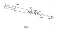
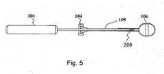
Fig. 1 is a schematic perspective view showing a balloon deflation tool used in the present invention.Fig. 2 is a schematic plan view showing a bead-feeding tool for creating a cavity in a bone of the present invention.Fig. 3 is a schematic perspective view showing thecartridge 204 used in the bead-feeding tool shown inFig. 2 , which is for storing and supplyingbeads 208.Fig. 4 is a schematic partial cross-sectional view showing thedriver 205 used in the bead-feeding tool shown inFig. 2 .Fig. 5 is a schematic partial cross-sectional view showing that thebeads 208 inside theballoon 106 are withdrawn by inserting amagnetic rod 301 into theneedle conduit 105.- A method is disclosed for creating a cavity in a bone comprising (a) preparing filler particles capable of being retrieved from said cavity by a retrieving means, therein said retrieving means is capable of magnetically interacting with said filler particles; (b) inserting said filler particles into said bone by a feeding means to expand the bone to a desired volume; and (c) magnetically retrieving the filler particles from the expanded bone by said retrieving means.
- The method further comprises, prior to inserting the filler particles into the bone, inserting (preferably through a minimally invasively percutaneous path) a delivery tube into the bone; inserting said filler particles into said bone through said tube by said feeding means; and, after the bone is expanded to a desired volume, magnetically retrieving the filler particles from the expanded bone through the delivery tube by the retrieving mean.
- The method further comprises, prior to inserting the filler particles into the bone, inserting (preferably through a minimally invasively percutaneous path) a balloon into the bone; inserting said filler particles into said balloon by the feeding means to expand the balloon (or the bone) to a desired volume; magnetically retrieving the filler particles from the expanded balloon by the retrieving means; and retrieving the balloon from the expanded bone.
- Preferably, a method for creating a cavity in a bone comprises (a) preparing filler particles capable of being retrieved from said cavity by a retrieving means, therein said retrieving means is capable of attracting said filler particles by a magnetic force; (b) preparing a minimally invasive percutaneous path into said bone; (c) inserting a balloon into the bone through said path; (d) inserting said filler particles into said balloon by a feeding means to expand the balloon (or the bone) to a desired volume; (e) magnetically retrieving the filler particles from the expanded balloon by said retrieving means; and (f) retrieving the balloon from the expanded bone.
- The feeding means is preferably (not limited to) a plunger capable of being inserted into and retrieved from the bone (preferably through a minimally invasive percutaneous path).
- The retrieving means is preferably (not limited to) a plunger capable of being inserted into and retrieved from the bone (preferably through a minimally invasive percutaneous path), therein at least a portion of said retrieving means (preferably the distal portion) being magnetic or capable of being magnetized to be able to attract the filler particles by a magnetic force.
- The retrieving means is a hard (permanent) magnet or soft magnet (capable of being magnetized and de-magnetized), or comprises at least a portion in said means a hard magnet or a soft magnet.
- Said portion of said retrieving means being magnetic or capable of being magnetized to be able to attract the filler particles by a magnetic force is made from a magnetic material comprising (not limited to) Fe, Co and/or Ni-based alloys, Sm-Fe, Sm-Co and Sm-Co-Fe based alloys, Al-Ni-Co and Al-Ni-Fe-Co based alloys, Nd-Fe-B based alloys, Y-Co based alloys, Fe2O3, Fe3O4, BaO-Fe2O3 and SrO-Fe2O3 based ceramics.
- The feeding means and retrieving means can be solid, porous or hollow, and can be rigid, semi-rigid or flexible.
- The balloon is preferably connected to a distal end of said delivery tube, thereby the balloon may be carried into the bone by said tube, wherein the filler particles may be inserted into the balloon through the delivery tube.
- The balloon is preferably made from an inflatable, preferably inflatable and expandable, polymeric material (e.g., PU or rubber), although any material in any form which may serve the purpose may be used.
- The balloon may be impenetrable to air, penetrable to air, or penetrable to liquid. For air-impenetrable balloon, the delivery tube connected to the balloon may optionally incorporate on the inner wall of said tube at least a groove to help expel the air trapped within the balloon during inserting the filler particles into the balloon.
- The filler particles can be made from any material capable of being magnetically attracted by the retrieving means, for example, a Fe, Co and/or Ni based alloy.
- The filler particles are preferably in a granular form and have particle sizes smaller than about 3 mm, preferably smaller than about 2 mm, and more preferably smaller than 1 mm. (The particle size should not be too small to avoid embolism complication in case the balloon breaks inside bone).
- The filler particles can be solid, porous or hollow, and can be rigid or semi-rigid. For the sake of reducing particle weight (to make the magnetic retrieving process easier) and increasing the "lift" (the ability to push back compression-fractured bone), the filler particles are preferably rigid and hollow, as long as the strength of said hollow particles is sufficient to withstand the loading without being damaged or crushed during expansion process.
- The filler particles can be of any shape, but should avoid having sharp edges or corners which more easily damage the balloon. In general, particles of a spherical shape are easier to "flow," thereby increasing the "penetrating" ability of the particles (and the balloon). Particles of a square shape can develop a higher binding strength among particles (due to the larger particle-particle contact area) when the retrieving means is magnetically interacting with (attracting) the filler particles during retrieving procedure. This higher binding strength largely helps the retrieval of the filler particles from the expanded balloon. Combination of these two features (properties) is preferred.
- Preferably the filler particles are in a generally spherical shape with at least a portion of the particle surface being substantially flat. More preferably the filler particles are in a generally spherical shape with two portions on opposite sides (ends) being substantially flat. This shape of particles not only enhances the binding strength among particles, but also help direct (align) the filler particles into the delivery tube during retrieving procedure.
- A small amount of lubricant (e.g., water or oil) may be optionally added in the balloon or directly onto filler particles to lubricate the particles and help the filler "flow" within the balloon during feeding and/or retrieving procedures.
- The method may further comprises inserting a bone filler material into said cavity, therein said bone filler is preferably a biocompatible material, and more preferably a biocompatible and bioresorbable material, for example, calcium-based cement or particles or their composites.
- The bone being treated can be any kind of bone being damaged, fractured or diseased, for example, a compression-fractured vertebral body.
- A three-step process for creating a cavity in a bone, e.g. expanding a collapsed bone, according to one of the preferred embodiments of the present invention will be described in associated with devices constructed according to the present invention shown in the accompanied drawings.
- As shown in
Fig. 1 , aballoon 106 is fixedly mounted to a distal end of aneedle conduit 105. Theballoon 106 is made of elastic polyurethane or another suitable elastic material. Asyringe 101 is used to suck off the air contained in theballoon 106, wherein a proximal end of theneedle conduit 105 is connected to asuction conduit 103 with aconnector 104, and thesuction conduit 103 is then connected to thesyringe 101 with a three-way valve 102 being turned on. Once theballoon 106 is deflated, the three-way valve 102 is turned off. Theneedle conduit 105 together with the deflatedballoon 106 are ready to be inserted into a bone (not shown in the drawings) through a minimally invasive percutaneous path (not shown in the drawings). Thesuction conduit 103 is disconnected from theconnector 104 when theballoon 106 is inside the bone. - A feeding tool is assembled for filling the
balloon 106 with metallic beads made of Fe, Co or Ni based alloy. As shown inFigs. 2 to 4 , the feeding tool comprises acartridge 204;beads 208 in saidcartridge 204; and adriver 205. Thedriver 205 has acylindrical cartridge base 203 provided with alongitudinal channel 21 therein and alongitudinal slit 22 which is in fluid communication and aligned with thelongitudinal channel 21; apiston base 201; and apiston 202 movably received in saidpiston base 201. Thecartridge 204 has a threadedstud 23 formed on a bottom surface thereof and two opposite throughholes 24 on the front and rear sides (only one throughhole 24 is shown inFig. 3 ) inear the bottom surface. Thecartridge 204 is intimately received in saidlongitudinal slit 22 and the throughholes 24 are aligned with thelongitudinal channel 21, so that thebeads 208 in saidcartridge 204 flow into thelongitudinal channel 21 without leaking. Anut 207 is threaded into the threadedstud 23 to fix thecartridge 204 onto thecartridge base 203. Thepiston 202 has arod portion 25 and a threadedportion 26, wherein the threadedportion 26 is threadedly engaged with a proximal end of thepiston base 201. A distal end of saidpiston base 201 is connected to a proximal end of thecartridge base 203 with therod portion 25 of the piston being aligned with thelongitudinal channel 21 of the cartridge base, thereby saidrod portion 25 can advance and retreat in thelongitudinal channel 21 and thecartridge 204 when the threadedportion 26 is clockwise and counterclockwise rotated relatively to thepiston base 201. The assembly of the feeding tool is now completed, and it is then connected to theneedle conduit 105 by connecting a distal end of thecartridge base 203 to theconnector 204. - The
piston 202 is able to be driven by an operator to push saidbeads 208 flown into saiddriver 205 into saidneedle conduit 105 and finally into saidballoon 106, wherein a distal end of therod portion 25 travels through thecartridge 204 and thelongitudinal channel 21 separated by thecartridge 204 and reaches theballoon 106.Said piston 202 is then driven backward from saidballoon 106, passing theneedle conduit 105, thelongitudinal channel 21, and thecartridge 204, to let saidbeads 208 in saidcartridge 204 flow into said driver 205 (the longitudinal channel 21) again. Apressing member 206 is slidably received in thecartridge 204, pressing thebeads 208 therein, to eliminate a space created in theneedle conduit 105 and thedriver 205, when thepiston 202 is being driven away from saidballoon 106. Theballoon 106 will be dilated with thebeads 208 to a predetermined size (i.e. predetermined amount of beads) by repeatedly driving thepiston 202 back-and-forth. The feeding tool is then separated from theconnector 104. - The
beads 208 inside theballoon 106 are withdrawn by inserting amagnetic rod 301 into theneedle conduit 105 as shown inFig. 5 . Themagnetic rod 301 is provided with a permanent magnet at its front end, and thebeads 208 in theballoon 106 are attracted by and attached to the approaching permanent magnet. Themagnetic rod 301 is then pulled out from theneedle conduit 105 to retrieve the beads attached to its front end. Theballoon 106 is removed from the bone cavity by pulling out theconnector 104 together with theneedle conduit 105, when all thebeads 208 inside theballoon 106 have been withdrawn by repeatedly inserting and pulling themagnetic rod 301 in and out theballoon 106. Optionally, Step 1 may be carried out to deflate theballoon 106 prior to pulling out theballoon 106 from the bone cavity. - Although the present invention has been described with reference to specific details of certain embodiments thereof, it is not intended that such details should be regarded as limitations upon the scope of the present invention. Many modifications and variations are possible in light of the above disclosure.
Claims (14)
- A device for using beads (208) to create a cavity in a bone comprising beads (208), comprising a needle conduit (105); a connector (104); a reservoir (204), wherein said beads (208) are in said reservoir (204) ; a driver (205) having a piston (202), wherein a proximal end of said needle conduit (105) is connected to said driver (205) with said connector (104), said reservoir (204) is in fluid communication with said driver (205) so that said beads (208) flow into said driver (205), and said piston (202) is able to be driven by an operator to push said beads (208) flown into said driver (205) into said needle conduit (105) and said piston (202) is able to be pulled away from said needle conduit (105) after said pushing to let said beads (208) flow from said reservoir (204) into said driver (205);characterized in that
said beads (208) are flowable metallic beads (208) able to be attracted by a magnet, and
said device further comprisesa) means adapted for introducing said beads (208) into a bone by applying a pressure on said beads (208) ; andb) a magnet suitable for withdrawing said beads (208) from said bone by magnetic force. - The device of claim 1 further comprising a pocket adapted to be disposed in said bone, wherein said pocket has an inlet connected to said introduction means to let said beads (208) into and out off said pocket, wherein said introduction and said withdraw of said beads (208) are with respect to said pocket.
- The device of claim 2 wherein said inlet of said pocket is fixedly connected to or formed at one end of a tube of said introduction means, so that said beads (208) can be introduced into said pocket via said tube.
- The device of claim 1 wherein said introduction means a) comprises a tube having one end adapted to be inserted into said bone; means for feeding said beads (208) into said tube; and a driver (205) for pushing said beads (208) inside said tube from another end of said tube.
- The device of claim 3 wherein said introduction means a) comprises means for feeding said beads into said tube; and a driver (205) for pushing said beads (208) inside said tube from another end of said tube.
- The device of claims 4 or 5, wherein said magnet b) is adapted to be inserted into said tube from said another end to approach said beads (208) in said bone or said pocket, so that said beads (208) attached to said magnet can be retreated from said bone or said pocket
- The device of claim 1, wherein said driver (205) and said reservoir (204) form a three-way structure, and said reservoir (204) is located between two ends of the three-way structure, wherein said needle conduit (105) and said piston (202) are located at said two ends of the three-way structure.
- The device of claim 1 further comprising a press member in contact with the beads (208) in said reservoir (204), which presses the beads (208) in the reservoir (204) to enter the driver (205), so that a space created in the driver (205) is eliminated when the piston (202) is being pulled away from said needle conduit (105).
- The device of claim 7, wherein said piston (202) is linearly movable in said three-way structure.
- The device of claim 1 further comprising a pocket fixedly connected to or formed at a distal end of said needle conduit (105).
- The device of claim 10, wherein said pocket is a balloon (106).
- The device of claim 1, wherein said driver (202) comprises a cylindrical reservoir base (203) having a longitudinal channel (21) therein and a longitudinal slit (22) which is in fluid communication and aligned with the longitudinal channel (21); a piston base (201) in which the piston (202) is movably received, wherein said reservoir (204) is intimately received in said longitudinal slit (22) so that said beads (208) in said reservoir (204) flow into the longitudinal channel (21) of the reservoir base (203) without leaking; said proximal end of said needle conduit (105) is connected to a distal end of the reservoir base (203) with said needle conduit (105) being in fluid communication and aligned with the longitudinal channel (21) of the reservoir base (203); and a distal end of said piston base (201) is connected to a proximal end of the reservoir base (203) with the piston (202) being aligned with the longitudinal channel (21) of the reservoir base (203), so that the piston (202) can advance and retreat in the longitudinal channel (21) of the reservoir base (203) and in the needle conduit (105).
- The device of claim 12, wherein said piston (202) comprises a rod portion (25) and a threaded portion (26), wherein said rod portion (25) advances and retreats in the longitudinal channel (21) of the reservoir base (203) and the needle conduit (105) while the threaded portion is threadedly engaged with a proximal end of the piston base (201).
- The device of claim 10 further comprising a magnetic rod (301) having said magnet at one end, which is adapted to be inserted into the needle conduit (105) with its magnet approaching said pocket.
Applications Claiming Priority (2)
| Application Number | Priority Date | Filing Date | Title |
|---|---|---|---|
| US99320207P | 2007-09-11 | 2007-09-11 | |
| PCT/US2008/010452WO2009035549A1 (en) | 2007-09-11 | 2008-09-08 | Bone cavity creation system and method with magnetic force retrievable beads |
Publications (3)
| Publication Number | Publication Date |
|---|---|
| EP2190360A1 EP2190360A1 (en) | 2010-06-02 |
| EP2190360A4 EP2190360A4 (en) | 2012-08-01 |
| EP2190360B1true EP2190360B1 (en) | 2015-07-29 |
Family
ID=40452313
Family Applications (1)
| Application Number | Title | Priority Date | Filing Date |
|---|---|---|---|
| EP08830509.9ANot-in-forceEP2190360B1 (en) | 2007-09-11 | 2008-09-08 | Bone cavity creation system with magnetic force retrievable beads |
Country Status (6)
| Country | Link |
|---|---|
| US (1) | US8480678B2 (en) |
| EP (1) | EP2190360B1 (en) |
| JP (1) | JP5331810B2 (en) |
| CN (1) | CN101835431B (en) |
| TW (1) | TWI361058B (en) |
| WO (1) | WO2009035549A1 (en) |
Family Cites Families (10)
| Publication number | Priority date | Publication date | Assignee | Title |
|---|---|---|---|---|
| FR2287894A1 (en)* | 1974-10-15 | 1976-05-14 | Roussel Uclaf | Automatic pellet implanting device - for subcutaneous introduction of prods into animals |
| US6869445B1 (en)* | 2000-05-04 | 2005-03-22 | Phillips Plastics Corp. | Packable ceramic beads for bone repair |
| CN100584294C (en)* | 2002-08-27 | 2010-01-27 | 华沙整形外科股份有限公司 | System for intravertebral reduction |
| US8415407B2 (en)* | 2004-03-21 | 2013-04-09 | Depuy Spine, Inc. | Methods, materials, and apparatus for treating bone and other tissue |
| US6961620B2 (en)* | 2003-09-16 | 2005-11-01 | Boston Scientific Scimed, Inc. | Apparatus and methods for assisting ablation of tissue using magnetic beads |
| US9028829B2 (en)* | 2004-02-20 | 2015-05-12 | The Children's Hospital Of Philadelphia | Uniform field magnetization and targeting of therapeutic formulations |
| US20060085081A1 (en)* | 2004-06-07 | 2006-04-20 | Shadduck John H | Implants and methods for treating bone |
| EP1893109B1 (en)* | 2005-06-15 | 2017-10-04 | Joy Medical Devices Corporation | Tool and technique for continually delivering an orthopaedic paste |
| US20070093822A1 (en)* | 2005-09-28 | 2007-04-26 | Christof Dutoit | Apparatus and methods for vertebral augmentation using linked expandable bodies |
| US20070162132A1 (en)* | 2005-12-23 | 2007-07-12 | Dominique Messerli | Flexible elongated chain implant and method of supporting body tissue with same |
- 2008
- 2008-09-08EPEP08830509.9Apatent/EP2190360B1/ennot_activeNot-in-force
- 2008-09-08TWTW097134468Apatent/TWI361058B/ennot_activeIP Right Cessation
- 2008-09-08JPJP2010524046Apatent/JP5331810B2/ennot_activeExpired - Fee Related
- 2008-09-08CNCN2008801063551Apatent/CN101835431B/ennot_activeExpired - Fee Related
- 2008-09-08USUS12/733,545patent/US8480678B2/ennot_activeExpired - Fee Related
- 2008-09-08WOPCT/US2008/010452patent/WO2009035549A1/enactiveApplication Filing
Also Published As
| Publication number | Publication date |
|---|---|
| TW200922513A (en) | 2009-06-01 |
| EP2190360A1 (en) | 2010-06-02 |
| WO2009035549A1 (en) | 2009-03-19 |
| CN101835431B (en) | 2013-05-08 |
| TWI361058B (en) | 2012-04-01 |
| CN101835431A (en) | 2010-09-15 |
| JP2010538695A (en) | 2010-12-16 |
| US20110093025A1 (en) | 2011-04-21 |
| EP2190360A4 (en) | 2012-08-01 |
| US8480678B2 (en) | 2013-07-09 |
| JP5331810B2 (en) | 2013-10-30 |
Similar Documents
| Publication | Publication Date | Title |
|---|---|---|
| KR100948082B1 (en) | Tools and techniques for the continuous delivery of orthopedic pastes | |
| ES2430913T3 (en) | Minimally invasive spine stabilization and augmentation system | |
| US8771278B2 (en) | Systems and methods for vertebral or other bone structure height restoration and stabilization | |
| US8377131B2 (en) | Medical implant | |
| US8852276B2 (en) | Cosmetic surgery sizer | |
| US9095393B2 (en) | Method for balloon-aided vertebral augmentation | |
| US10874516B2 (en) | Implantable penile prostheses | |
| CN102686186A (en) | Penile prosthesis, penile prosthesis insertion tool and system thereof | |
| CN100569193C (en) | Tool and method for continuous delivery of orthopaedic paste | |
| EP2190360B1 (en) | Bone cavity creation system with magnetic force retrievable beads | |
| CN117898861A (en) | Inflatable penile prosthesis having a cylinder with a porous portion | |
| US9615863B2 (en) | Multichannel cannula for kyphoplasty and method of use | |
| CN112969432B (en) | Inflatable penile prosthesis and two-way valve pump | |
| US11571223B2 (en) | Device and method for cutting into a cancellous bone | |
| AU2014332328B2 (en) | Systems for balloon-aided vertebral augmentation | |
| CN103393452A (en) | Type-I bone cement injection device |
Legal Events
| Date | Code | Title | Description |
|---|---|---|---|
| PUAI | Public reference made under article 153(3) epc to a published international application that has entered the european phase | Free format text:ORIGINAL CODE: 0009012 | |
| 17P | Request for examination filed | Effective date:20100303 | |
| AK | Designated contracting states | Kind code of ref document:A1 Designated state(s):AT BE BG CH CY CZ DE DK EE ES FI FR GB GR HR HU IE IS IT LI LT LU LV MC MT NL NO PL PT RO SE SI SK TR | |
| AX | Request for extension of the european patent | Extension state:AL BA MK RS | |
| DAX | Request for extension of the european patent (deleted) | ||
| RAP1 | Party data changed (applicant data changed or rights of an application transferred) | Owner name:JOY MEDIAL DEVICES CORPORATION | |
| A4 | Supplementary search report drawn up and despatched | Effective date:20120703 | |
| RIC1 | Information provided on ipc code assigned before grant | Ipc:A61B 17/16 20060101AFI20120627BHEP | |
| 17Q | First examination report despatched | Effective date:20130910 | |
| GRAP | Despatch of communication of intention to grant a patent | Free format text:ORIGINAL CODE: EPIDOSNIGR1 | |
| INTG | Intention to grant announced | Effective date:20150211 | |
| GRAS | Grant fee paid | Free format text:ORIGINAL CODE: EPIDOSNIGR3 | |
| GRAA | (expected) grant | Free format text:ORIGINAL CODE: 0009210 | |
| AK | Designated contracting states | Kind code of ref document:B1 Designated state(s):AT BE BG CH CY CZ DE DK EE ES FI FR GB GR HR HU IE IS IT LI LT LU LV MC MT NL NO PL PT RO SE SI SK TR | |
| REG | Reference to a national code | Ref country code:GB Ref legal event code:FG4D | |
| REG | Reference to a national code | Ref country code:CH Ref legal event code:EP | |
| REG | Reference to a national code | Ref country code:AT Ref legal event code:REF Ref document number:738642 Country of ref document:AT Kind code of ref document:T Effective date:20150815 | |
| REG | Reference to a national code | Ref country code:IE Ref legal event code:FG4D | |
| REG | Reference to a national code | Ref country code:DE Ref legal event code:R096 Ref document number:602008039289 Country of ref document:DE | |
| REG | Reference to a national code | Ref country code:AT Ref legal event code:MK05 Ref document number:738642 Country of ref document:AT Kind code of ref document:T Effective date:20150729 | |
| REG | Reference to a national code | Ref country code:LT Ref legal event code:MG4D | |
| REG | Reference to a national code | Ref country code:NL Ref legal event code:MP Effective date:20150729 | |
| PG25 | Lapsed in a contracting state [announced via postgrant information from national office to epo] | Ref country code:FI Free format text:LAPSE BECAUSE OF FAILURE TO SUBMIT A TRANSLATION OF THE DESCRIPTION OR TO PAY THE FEE WITHIN THE PRESCRIBED TIME-LIMIT Effective date:20150729 Ref country code:GR Free format text:LAPSE BECAUSE OF FAILURE TO SUBMIT A TRANSLATION OF THE DESCRIPTION OR TO PAY THE FEE WITHIN THE PRESCRIBED TIME-LIMIT Effective date:20151030 Ref country code:LV Free format text:LAPSE BECAUSE OF FAILURE TO SUBMIT A TRANSLATION OF THE DESCRIPTION OR TO PAY THE FEE WITHIN THE PRESCRIBED TIME-LIMIT Effective date:20150729 Ref country code:NO Free format text:LAPSE BECAUSE OF FAILURE TO SUBMIT A TRANSLATION OF THE DESCRIPTION OR TO PAY THE FEE WITHIN THE PRESCRIBED TIME-LIMIT Effective date:20151029 Ref country code:LT Free format text:LAPSE BECAUSE OF FAILURE TO SUBMIT A TRANSLATION OF THE DESCRIPTION OR TO PAY THE FEE WITHIN THE PRESCRIBED TIME-LIMIT Effective date:20150729 | |
| PG25 | Lapsed in a contracting state [announced via postgrant information from national office to epo] | Ref country code:IS Free format text:LAPSE BECAUSE OF FAILURE TO SUBMIT A TRANSLATION OF THE DESCRIPTION OR TO PAY THE FEE WITHIN THE PRESCRIBED TIME-LIMIT Effective date:20151129 Ref country code:PL Free format text:LAPSE BECAUSE OF FAILURE TO SUBMIT A TRANSLATION OF THE DESCRIPTION OR TO PAY THE FEE WITHIN THE PRESCRIBED TIME-LIMIT Effective date:20150729 Ref country code:AT Free format text:LAPSE BECAUSE OF FAILURE TO SUBMIT A TRANSLATION OF THE DESCRIPTION OR TO PAY THE FEE WITHIN THE PRESCRIBED TIME-LIMIT Effective date:20150729 Ref country code:ES Free format text:LAPSE BECAUSE OF FAILURE TO SUBMIT A TRANSLATION OF THE DESCRIPTION OR TO PAY THE FEE WITHIN THE PRESCRIBED TIME-LIMIT Effective date:20150729 Ref country code:PT Free format text:LAPSE BECAUSE OF FAILURE TO SUBMIT A TRANSLATION OF THE DESCRIPTION OR TO PAY THE FEE WITHIN THE PRESCRIBED TIME-LIMIT Effective date:20151130 Ref country code:SE Free format text:LAPSE BECAUSE OF FAILURE TO SUBMIT A TRANSLATION OF THE DESCRIPTION OR TO PAY THE FEE WITHIN THE PRESCRIBED TIME-LIMIT Effective date:20150729 Ref country code:HR Free format text:LAPSE BECAUSE OF FAILURE TO SUBMIT A TRANSLATION OF THE DESCRIPTION OR TO PAY THE FEE WITHIN THE PRESCRIBED TIME-LIMIT Effective date:20150729 | |
| PG25 | Lapsed in a contracting state [announced via postgrant information from national office to epo] | Ref country code:NL Free format text:LAPSE BECAUSE OF FAILURE TO SUBMIT A TRANSLATION OF THE DESCRIPTION OR TO PAY THE FEE WITHIN THE PRESCRIBED TIME-LIMIT Effective date:20150729 | |
| PG25 | Lapsed in a contracting state [announced via postgrant information from national office to epo] | Ref country code:CZ Free format text:LAPSE BECAUSE OF FAILURE TO SUBMIT A TRANSLATION OF THE DESCRIPTION OR TO PAY THE FEE WITHIN THE PRESCRIBED TIME-LIMIT Effective date:20150729 Ref country code:DK Free format text:LAPSE BECAUSE OF FAILURE TO SUBMIT A TRANSLATION OF THE DESCRIPTION OR TO PAY THE FEE WITHIN THE PRESCRIBED TIME-LIMIT Effective date:20150729 Ref country code:SK Free format text:LAPSE BECAUSE OF FAILURE TO SUBMIT A TRANSLATION OF THE DESCRIPTION OR TO PAY THE FEE WITHIN THE PRESCRIBED TIME-LIMIT Effective date:20150729 Ref country code:IT Free format text:LAPSE BECAUSE OF FAILURE TO SUBMIT A TRANSLATION OF THE DESCRIPTION OR TO PAY THE FEE WITHIN THE PRESCRIBED TIME-LIMIT Effective date:20150729 Ref country code:EE Free format text:LAPSE BECAUSE OF FAILURE TO SUBMIT A TRANSLATION OF THE DESCRIPTION OR TO PAY THE FEE WITHIN THE PRESCRIBED TIME-LIMIT Effective date:20150729 Ref country code:LU Free format text:LAPSE BECAUSE OF FAILURE TO SUBMIT A TRANSLATION OF THE DESCRIPTION OR TO PAY THE FEE WITHIN THE PRESCRIBED TIME-LIMIT Effective date:20150908 Ref country code:MC Free format text:LAPSE BECAUSE OF FAILURE TO SUBMIT A TRANSLATION OF THE DESCRIPTION OR TO PAY THE FEE WITHIN THE PRESCRIBED TIME-LIMIT Effective date:20150729 | |
| REG | Reference to a national code | Ref country code:CH Ref legal event code:PL | |
| REG | Reference to a national code | Ref country code:DE Ref legal event code:R097 Ref document number:602008039289 Country of ref document:DE | |
| PG25 | Lapsed in a contracting state [announced via postgrant information from national office to epo] | Ref country code:RO Free format text:LAPSE BECAUSE OF FAILURE TO SUBMIT A TRANSLATION OF THE DESCRIPTION OR TO PAY THE FEE WITHIN THE PRESCRIBED TIME-LIMIT Effective date:20150729 | |
| PLBE | No opposition filed within time limit | Free format text:ORIGINAL CODE: 0009261 | |
| STAA | Information on the status of an ep patent application or granted ep patent | Free format text:STATUS: NO OPPOSITION FILED WITHIN TIME LIMIT | |
| REG | Reference to a national code | Ref country code:IE Ref legal event code:MM4A | |
| 26N | No opposition filed | Effective date:20160502 | |
| PG25 | Lapsed in a contracting state [announced via postgrant information from national office to epo] | Ref country code:LI Free format text:LAPSE BECAUSE OF NON-PAYMENT OF DUE FEES Effective date:20150930 Ref country code:IE Free format text:LAPSE BECAUSE OF NON-PAYMENT OF DUE FEES Effective date:20150908 Ref country code:CH Free format text:LAPSE BECAUSE OF NON-PAYMENT OF DUE FEES Effective date:20150930 | |
| PG25 | Lapsed in a contracting state [announced via postgrant information from national office to epo] | Ref country code:SI Free format text:LAPSE BECAUSE OF FAILURE TO SUBMIT A TRANSLATION OF THE DESCRIPTION OR TO PAY THE FEE WITHIN THE PRESCRIBED TIME-LIMIT Effective date:20150729 | |
| REG | Reference to a national code | Ref country code:FR Ref legal event code:PLFP Year of fee payment:9 | |
| PG25 | Lapsed in a contracting state [announced via postgrant information from national office to epo] | Ref country code:BE Free format text:LAPSE BECAUSE OF FAILURE TO SUBMIT A TRANSLATION OF THE DESCRIPTION OR TO PAY THE FEE WITHIN THE PRESCRIBED TIME-LIMIT Effective date:20150729 | |
| PG25 | Lapsed in a contracting state [announced via postgrant information from national office to epo] | Ref country code:MT Free format text:LAPSE BECAUSE OF FAILURE TO SUBMIT A TRANSLATION OF THE DESCRIPTION OR TO PAY THE FEE WITHIN THE PRESCRIBED TIME-LIMIT Effective date:20150729 | |
| PG25 | Lapsed in a contracting state [announced via postgrant information from national office to epo] | Ref country code:HU Free format text:LAPSE BECAUSE OF FAILURE TO SUBMIT A TRANSLATION OF THE DESCRIPTION OR TO PAY THE FEE WITHIN THE PRESCRIBED TIME-LIMIT; INVALID AB INITIO Effective date:20080908 Ref country code:BG Free format text:LAPSE BECAUSE OF FAILURE TO SUBMIT A TRANSLATION OF THE DESCRIPTION OR TO PAY THE FEE WITHIN THE PRESCRIBED TIME-LIMIT Effective date:20150729 | |
| PG25 | Lapsed in a contracting state [announced via postgrant information from national office to epo] | Ref country code:CY Free format text:LAPSE BECAUSE OF FAILURE TO SUBMIT A TRANSLATION OF THE DESCRIPTION OR TO PAY THE FEE WITHIN THE PRESCRIBED TIME-LIMIT Effective date:20150729 | |
| PG25 | Lapsed in a contracting state [announced via postgrant information from national office to epo] | Ref country code:TR Free format text:LAPSE BECAUSE OF FAILURE TO SUBMIT A TRANSLATION OF THE DESCRIPTION OR TO PAY THE FEE WITHIN THE PRESCRIBED TIME-LIMIT Effective date:20150729 | |
| REG | Reference to a national code | Ref country code:FR Ref legal event code:PLFP Year of fee payment:10 | |
| REG | Reference to a national code | Ref country code:FR Ref legal event code:PLFP Year of fee payment:11 | |
| PGFP | Annual fee paid to national office [announced via postgrant information from national office to epo] | Ref country code:FR Payment date:20190925 Year of fee payment:12 Ref country code:DE Payment date:20190925 Year of fee payment:12 | |
| PGFP | Annual fee paid to national office [announced via postgrant information from national office to epo] | Ref country code:GB Payment date:20190926 Year of fee payment:12 | |
| REG | Reference to a national code | Ref country code:DE Ref legal event code:R119 Ref document number:602008039289 Country of ref document:DE | |
| GBPC | Gb: european patent ceased through non-payment of renewal fee | Effective date:20200908 | |
| PG25 | Lapsed in a contracting state [announced via postgrant information from national office to epo] | Ref country code:FR Free format text:LAPSE BECAUSE OF NON-PAYMENT OF DUE FEES Effective date:20200930 Ref country code:DE Free format text:LAPSE BECAUSE OF NON-PAYMENT OF DUE FEES Effective date:20210401 | |
| PG25 | Lapsed in a contracting state [announced via postgrant information from national office to epo] | Ref country code:GB Free format text:LAPSE BECAUSE OF NON-PAYMENT OF DUE FEES Effective date:20200908 |