EP2190325B1 - Instant extraction cup - Google Patents
Instant extraction cupDownload PDFInfo
- Publication number
- EP2190325B1 EP2190325B1EP08738130AEP08738130AEP2190325B1EP 2190325 B1EP2190325 B1EP 2190325B1EP 08738130 AEP08738130 AEP 08738130AEP 08738130 AEP08738130 AEP 08738130AEP 2190325 B1EP2190325 B1EP 2190325B1
- Authority
- EP
- European Patent Office
- Prior art keywords
- cup
- brewing cup
- set forth
- brewing
- coffee
- Prior art date
- Legal status (The legal status is an assumption and is not a legal conclusion. Google has not performed a legal analysis and makes no representation as to the accuracy of the status listed.)
- Active
Links
- 238000000605extractionMethods0.000titledescription8
- 239000007788liquidSubstances0.000claimsabstractdescription28
- 235000013361beverageNutrition0.000claimsabstractdescription20
- 239000000463materialSubstances0.000claimsabstractdescription20
- 239000004615ingredientSubstances0.000claimsabstractdescription15
- 239000000126substanceSubstances0.000claimsabstractdescription10
- 231100000252nontoxicToxicity0.000claimsabstract2
- 230000003000nontoxic effectEffects0.000claimsabstract2
- 239000000123paperSubstances0.000claimsdescription59
- XLYOFNOQVPJJNP-UHFFFAOYSA-NwaterSubstancesOXLYOFNOQVPJJNP-UHFFFAOYSA-N0.000claimsdescription35
- 238000000034methodMethods0.000claimsdescription28
- 239000004793PolystyreneSubstances0.000claimsdescription19
- 229920002223polystyrenePolymers0.000claimsdescription19
- 230000005484gravityEffects0.000claimsdescription9
- 229920002472StarchPolymers0.000claimsdescription7
- 235000019698starchNutrition0.000claimsdescription7
- 239000008107starchSubstances0.000claimsdescription7
- 239000000835fiberSubstances0.000claimsdescription5
- 229920003023plasticPolymers0.000claimsdescription5
- 239000004033plasticSubstances0.000claimsdescription5
- 150000001875compoundsChemical class0.000claimsdescription4
- 239000011087paperboardSubstances0.000claimsdescription4
- 238000007789sealingMethods0.000claimsdescription4
- 239000004621biodegradable polymerSubstances0.000claimsdescription3
- 229920000620organic polymerPolymers0.000claimsdescription2
- 238000003756stirringMethods0.000abstractdescription12
- 235000013353coffee beverageNutrition0.000description77
- 235000016213coffeeNutrition0.000description70
- 238000005520cutting processMethods0.000description24
- 235000013616teaNutrition0.000description18
- 239000000203mixtureSubstances0.000description17
- 241001122767TheaceaeSpecies0.000description15
- 230000008569processEffects0.000description15
- 239000004698PolyethyleneSubstances0.000description12
- -1polyethylenePolymers0.000description11
- 229920000573polyethylenePolymers0.000description10
- 238000013124brewing processMethods0.000description9
- 239000000843powderSubstances0.000description8
- 235000013305foodNutrition0.000description6
- 230000008901benefitEffects0.000description5
- 235000019640tasteNutrition0.000description5
- 235000021539instant coffeeNutrition0.000description4
- 238000004519manufacturing processMethods0.000description4
- 230000007246mechanismEffects0.000description4
- 230000004048modificationEffects0.000description4
- 238000012986modificationMethods0.000description4
- 238000012360testing methodMethods0.000description4
- 230000008859changeEffects0.000description3
- UHZZMRAGKVHANO-UHFFFAOYSA-Mchlormequat chlorideChemical compound[Cl-].C[N+](C)(C)CCClUHZZMRAGKVHANO-UHFFFAOYSA-M0.000description3
- 238000013461designMethods0.000description3
- 230000000694effectsEffects0.000description3
- 239000000284extractSubstances0.000description3
- 239000000155meltSubstances0.000description3
- 238000002360preparation methodMethods0.000description3
- 235000019658bitter tasteNutrition0.000description2
- 239000011248coating agentSubstances0.000description2
- 238000000576coating methodMethods0.000description2
- 238000001914filtrationMethods0.000description2
- 235000003599food sweetenerNutrition0.000description2
- 238000010438heat treatmentMethods0.000description2
- 235000012171hot beverageNutrition0.000description2
- 238000001802infusionMethods0.000description2
- VIKNJXKGJWUCNN-XGXHKTLJSA-NnorethisteroneChemical compoundO=C1CC[C@@H]2[C@H]3CC[C@](C)([C@](CC4)(O)C#C)[C@@H]4[C@@H]3CCC2=C1VIKNJXKGJWUCNN-XGXHKTLJSA-N0.000description2
- 239000011148porous materialSubstances0.000description2
- 229910000679solderInorganic materials0.000description2
- 239000003765sweetening agentSubstances0.000description2
- 235000017166Bambusa arundinaceaNutrition0.000description1
- 235000017491Bambusa tuldaNutrition0.000description1
- 244000082204Phyllostachys viridisSpecies0.000description1
- 235000015334Phyllostachys viridisNutrition0.000description1
- 241000533293Sesbania emerusSpecies0.000description1
- 238000009825accumulationMethods0.000description1
- 230000004075alterationEffects0.000description1
- 230000000712assemblyEffects0.000description1
- 238000000429assemblyMethods0.000description1
- 235000019606astringent tasteNutrition0.000description1
- 239000011425bambooSubstances0.000description1
- 238000009835boilingMethods0.000description1
- 238000004364calculation methodMethods0.000description1
- 235000015116cappuccinoNutrition0.000description1
- 239000002131composite materialSubstances0.000description1
- 239000006071creamSubstances0.000description1
- 230000007812deficiencyEffects0.000description1
- 230000003111delayed effectEffects0.000description1
- 229910003460diamondInorganic materials0.000description1
- 239000010432diamondSubstances0.000description1
- 238000001035dryingMethods0.000description1
- 238000005516engineering processMethods0.000description1
- 239000000796flavoring agentSubstances0.000description1
- 235000019634flavorsNutrition0.000description1
- 239000012530fluidSubstances0.000description1
- 239000003779heat-resistant materialSubstances0.000description1
- 238000007654immersionMethods0.000description1
- 230000002452interceptive effectEffects0.000description1
- 238000010409ironingMethods0.000description1
- 238000005259measurementMethods0.000description1
- 239000002184metalSubstances0.000description1
- 238000000465mouldingMethods0.000description1
- 239000008239natural waterSubstances0.000description1
- 239000012057packaged powderSubstances0.000description1
- 239000002245particleSubstances0.000description1
- 230000000149penetrating effectEffects0.000description1
- 230000002035prolonged effectEffects0.000description1
- 238000004064recyclingMethods0.000description1
- 229920005989resinPolymers0.000description1
- 239000011347resinSubstances0.000description1
- 238000000926separation methodMethods0.000description1
- 239000007787solidSubstances0.000description1
- 235000021481specialty coffeeNutrition0.000description1
- 239000007921spraySubstances0.000description1
- 229910001220stainless steelInorganic materials0.000description1
- 239000010935stainless steelSubstances0.000description1
- 229920001059synthetic polymerPolymers0.000description1
- 238000012956testing procedureMethods0.000description1
- 238000005406washingMethods0.000description1
Images


Classifications
- A—HUMAN NECESSITIES
- A47—FURNITURE; DOMESTIC ARTICLES OR APPLIANCES; COFFEE MILLS; SPICE MILLS; SUCTION CLEANERS IN GENERAL
- A47J—KITCHEN EQUIPMENT; COFFEE MILLS; SPICE MILLS; APPARATUS FOR MAKING BEVERAGES
- A47J31/00—Apparatus for making beverages
- A47J31/02—Coffee-making machines with removable extraction cups, to be placed on top of drinking-vessels i.e. coffee-makers with removable brewing vessels, to be placed on top of beverage containers, into which hot water is poured, e.g. cafe filter
Definitions
- the inventionrelates to disposable hot beverage brewing apparatuses, such as for coffee, tea and herbal products. More particularly, the invention relates to hot beverage disposable containers that contain filter papers that trap solids within the container yet enable fluid to pass.
- the liquid penetrabilityhas been designed through the cup's holes/cutting areas that allow the liquid to penetrate into a lower reservoir cup at a consumer's time limit preferences. The arrangements of how many holes or how big the cutting area will result in how long the extraction should take place (e.g. 2 minutes; 3.5 minutes; or 5 minutes).
- this inventionhas been designed to provide a proper time and space to provide a stirring movement in a pre packaged 3 in 1 (i.e., coffee, sugar and powder creamer) coffee mix product that comes in a small sachet for one serving.
- the time and space to properly stiris critical in a 3 in 1 coffee mix preparation. Without stirring, the powder creamer that has been homogenously mixed with sugar and coffee, when in contact with hot water will form fat layer (shield effect) that makes the hot water hard to penetrate into the rest of the mixture. The 3 in 1 coffee mix will become clogged and will form a glutinous like compound which makes the extraction process improperly done.
- a brewing apparatusthat allows proper stirring is important especially in a pre packaged beverage mixture that contains powder creamer as one of its major ingredients.
- Coffeehas been consumed and is known as the oldest beverage in many parts of the world. Thus, there are various devices that have been used to brew coffee. Traditionally, coffee grounds have been brewed in a coffee pot (infusion). Later on, people preferred to brew in electric drip coffee machine due to its conveniences. Moreover, due to the advance of spray-dried technology, instant coffee also has been a choice to many people. These are fair methods to enjoy a cup of coffee; however each one of them has their own drawbacks due to timing, mobility and the fullness of the taste and aroma.
- a product in this categorycan be categorized as a close-brewing system. In this system, the user is not allowed to perform any kind of modification on the product. This system offers no flexibility to the user either to add or to reduce, for instance, the quantity of the coffee grounds into the pouch/bag.
- US Patent no. 4619830Napier; Edward D. Scarborough, Ontario, CA ) discloses a brewing apparatus that employed an open-brewing-system that offers a user more flexibility either to add or to reduce, for instance, the quantity of the coffee ground, sugar or powder creamer into the beverage.
- its supporting stick/rod in the middle of its top openinghas made it uneasy or troublesome for the user in performing a proper stirring motion during beverage preparation.
- Coffee, tea and herbal productsare very sophisticated products. Each required a certain special treatment to get its utmost benefit. Since, all required hot water to extract the sophisticated ingredient contained therein, using a correct brewing apparatus is critical. This invention has been designed to give an accurate result in brewing time.
- This inventionhas four primary goals. One is to offer to the public an apparatus that correct and accurate, based on written recommendation from Specialty Coffee Association of America, concerning " how long " coffee ground should be in contact with hot water in order to prepare an excellent cup of coffee beverage. Two is to provide an open system brewing apparatus that allows the public to have more flexibility to choose what kind of ingredients to be brewed. Three is to provide a brewing apparatus that has a hot steam releasing vent and also that can be positioned snuggly on top of a regular coffee mug or disposable paper cup. Four is to provide brewing apparatus that is easily stirable in brewing 3 in 1 pre packaged powder beverage that contain powder creamer as one of its major ingredients.
- a cup containercomprises a disposable liquid permeable brewing filter that has an open top and partial closed bottom. It is made of coated paper, or polyethylene, or polystyrene, or biodegradable substances including but are not limited to substances such as modified and or unmodified organic fibers and or pulp and or starch or any combination thereof that has number of holes or cutting areas on the bottom of the cup.
- the number of holes or cutting areasis the time control mechanism which produces a critical role in controlling the flow of the liquid from this invention to the bottom of a reservoir cup or mug.
- Each holerepresents 28.26 millimeter square. Although the size is perfect to create raindrop size droplets, the hole/cutting area can be varied in size.
- the perforation of the inventioncomprises an arrangement of about 16.9% (diameter of ( ⁇ )15 mm) to 9.1% ( ⁇ 11 mm) by ratio to the brewers cup bottom base (4183.3 mm 2 ); more preferably from about 7.5% ( ⁇ 10 mm) to 3.7% ( ⁇ 7 mm); more preferably still, from about 2.7% ( ⁇ 6 mm) to 0.68% ( ⁇ 3 mm).
- the shape of the brewer's bottom base opening areacan be modified into many kinds of shapes.
- Such modification to the bottom base of the brewer cupis desirable to enhance its aesthetic appearances include, but are not limited to, triangle, rectangle, oval, diamond, flower petal, star, circle, heart, crescent, fan, nonagon, octagon, pentagon, decagon, and hexagon, or any combination thereof.
- the cup's bottomhas been designed with four concave shapes that are inwardly curving which, in this embodiment, are used to release hot steam buildup during brewing process.
- these cornersallowed hot steam that is accumulated on the reservoir cup to be escaped.
- the ventis important to create a resistant-free environment of the liquid flow from top to bottom during brewing process.
- the number of petal shape cornercan be maximize or minimize accordingly to the desired output of hot steam released rate.
- the filter paper or other porous materialattaches onto the bottom of the cup assembly through hot seal or food grade starch.
- the heat sealis applied about 5 mm width circling along the outer edge of the filter paper onto the cup's bottom.
- the 5 mm heat seal widthprovides some stretching flexibility to form a better pressure point during droplets drip-down process.
- One alternative embodiment to re-use the cup assembly and throw away the used filter paper in order to preserve natural resources for a better clean environmentcan be achieved if the filter paper can be easily peeled off by user.
- the hot sealcan be done because the commercial filter paper contained Poly Ethylene on one of its side. When applied to heat, PE material melts and become part of the cup assembly.
- the brewing receptacle with multiple holes arrangementhas a more stable result than in the other arrangement. And also with the same ratio, multiple holes arrangement has proved to be faster than one single cut arrangement. It is because every cutting area has a pressure point on the middle of that opening. When the filter paper gets wet from the hot water and receives gravity forces, the filter paper will stretch a little and arch in a way to form a pressure point where most of the liquid drips during brewing process. In conclusion to our test, the greater the number of outlets, the faster it will allow the liquid to pass through the filter paper into the reservoir cup/mug.
- the testalso showed that one single cut arrangement, for example with 13.51% ratio, has a slower rate (8 second and 53 milli second) result in reaching the 120 ml marking level than 20 multiple cutting arrangement (3 second and 85 milli second) that also has a same ratio.
- the one cutting arrangementhas also proved to be less stable and unreliable as a time control mechanism.
- the inventiongenerally provides a disposable brewing apparatus made of inexpensive material such as coated paper board or polystyrene or polyethylene and filter paper. In one alternative, it can also be used to preserve natural resources when just the filter paper is the only part of the entire assembly to be discarded after use.
- a drip-type coffee, or herbal or tea brewer apparatuscomprises a disposable cup 10 which can be made from material include but is not limited to a group consisting of polystyrene compounds, plastic, organic and or non organic Bio-degradable polymer, and or modified and or unmodified organic fibers and or pulp and or starch and or coated paperboard and or a combination thereof.
- a partial closed bottom 110that has an outer diameter about 7.3 cm and sidewalls 105 tapering outwardly towards the top open mouth 103 that has an outer diameter about 8.5 cm.
- the filter cup 10is constructed of a water permeable or porous material, preferably commercial filter paper 121 which has substantial durability when it is in a wet condition, and which is coated with Polyethylene on one side and comparatively inexpensive so that it can be discarded after a single use.
- the filter paper 121is attached to the bottom base 110 of the filter cup 10 through heat seal or food grade starch or ultrasonic sealing system or supersonic sealing system.
- the filter cup 10is designed with plurality number of holes 108 on its bottom base 110 as a time control mechanism which is fundamental to brew different kind of ingredients as each ingredient seems to be needed different time limit to be properly and correctly extracted.
- the area to be hot sealis as wide as around 5 mm along the rim of the circular shape of the filter paper.
- Each hole 108 of the inventionrepresents 28.26 mm2.
- the size of the hole/cutting area 108can be varied, this size is perfect to create natural water droplets size.
- the accumulation of the water on the pressure point 625is turned into its maximum size before it starts to drop down as a droplet which falling into a range between 3mm in diameter to 8mm.
- the droplet size when reached to its maximum sizedoes not change accordingly with the perforation change into a bigger size. Therefore to keep it in the maximum range of droplet size will become the most effective way to control drip down process in this type of filter brewer. This is one critical point that set apart this invention from the other inventions that has bigger or too small perforation outlet arrangement.
- Arrangement of the holes or cutting areas 108is designed to be separated at least 3 mm apart from each hole. This is important to create an individual droplet 630 ( Fig.6 ) without interference from another droplet 630 which is positioned too close to one and another, in order to maintain a standard dropping rate.
- the major benefit of this designis that it creates an independent and uniform size of droplets. As learned from trials, the more standard the dropping rate the more precise its function as a time controlling mechanism. Also the more output to release gravity force the faster it is in accommodating a faster brewing rate.
- a pressure point 625developed on each and every opening/cutting area when the hot water poured down on the filter cup 10.
- the gravity forcepushes down the hot water which in its natural way forms an arch shape that has the lowest point that we refer to pressure point 625 on the filter paper 121.
- There is a plurality of pressure points 625 in Fig.6while the embodiment of Fig. 7 has only one. Although bigger in cutting size, pressure point 625 in Fig. 7 results in unstable and unpredictable droplets 630.
- the pressure point in Fig.6which resulted from multiple holes arrangement is more predictable and, as set forth in Table 1, proved to be more stable.
- the heat seal area 109( Fig. 3 and Fig. 4 ) is applied at about a 5 mm width circling along the outer edge of the filter paper 121 onto the cup's bottom 110.
- the 5 mm heat seal widthprovides some stretching flexibility to form a better pressure point 625 ( Fig. 8 ) during the droplets drip-down process.
- the hot sealis possible because the commercial filter paper 121 contains Poly Ethylene on one of its sides. When subjected to heat, the PE material melts and become part of the cup assembly.
- this inventionprovides a hot steam escaping route.
- the filter cup 10provides four (4) hot steam escaping vents 201 ( Fig. 1 and Fig. 5a ) on its lower part of the outer sidewall 105.
- the accumulated hot steamhas been a problem in brewing devices that are telescopingly assembled.
- the hot steam trapped in the lower liquid receiving cuphas been one culprit of the slower extraction process.
- the trapped hot steamhas accumulated into a massive force pushing up and thus delayed the drip down process. This indicates that the gravity force is not working in this condition as it is supposed to be.
- the inventionhas four concave shapes vent 201 that are inwardly curving as deep as about 6 mm; as wide as about 1 cm and tapered upwardly as high as about 2.5 cm.
- the vent 201 main functionsare to avoid pressure build-up which can prolong the brewing time during brewing process in the reservoir mug.
- these vents 201allowed hot steam that is accumulated on the reservoir cup to be escaped ( Fig.1 ).
- the number of petal shape cornercan be maximize or minimize accordingly to the desired output of hot steam released (HSR) rate.
- HSRhot steam released
- the filter cup 10uses the least filter paper 121 amongst any other similar product and is especially most efficient when compared to a tea bag for brewing tea beverage.
- this invention embodimentthat has six (6) holes arrangement resulted in about two minutes brewing time which is the same as that recommended in most tea bag brewing methods.
- most tea bagrequires 13.140mm2 (with a length of 146mm and width 90mm) of filter paper while this invention needs only 4183 mm2 (3.14 x 36.5mm x 36.5mm) filter paper that is 300% more efficient than most tea bag assemblies in using filter paper.
- an individual hole sealing systemis possible to be applied.
- each individual hole 108 with diameter of 5 mmneeds only one circular filter paper with diameter of 7 mm to be entirely covered.
- this fabricating methodone can save up to 75% of current use (4183.3mm2) and almost 1400% (13140 mm2 divided by 923 mm2) more efficient than most of the tea bag requirements in using filter paper.
- the filter cup 10is not wasting any unnecessary filter paper 121 like the other brewing methods.
- the filter cup 10When telescopically engaged into the mouth of the reservoir cup or mug 11 that has a top inner side opening range between 7.2 cm in diameter to 7.5 cm in diameter, the filter cup 10 will fit snuggly on the reservoir cup without any holder.
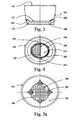
- the filter cup 10uses attachable thin (about 3 mm thick x 2.5 cm x 2 cm) rectangular shape polystyrene sheets 610 ( Fig. 2 ) on the bottom part of the outer side of the cup.
- the number of thin polystyrene sheets 610can be used from one sheet to more than one according to the reservoir's cup top opening width.
- the thin polystyrene sheet 610can be pre-attached on the filter cup 10 during fabrication or it can be provided with double-sided-tape and attached by user whenever needed.
- the telescopically engagement of the embodimentis the most practical way to hold the cup receptacle firmly with the reservoir cup and thus provide a unique coffee or tea disposable brewer "On the Go" for the portable public.
- the filter cup 10uses perfectly fit sit-on-ring 233 ( Fig. 9 and Fig. 10 ) which is rounded in shape and has three supporting jagged legs 238 that each has a length about 3.5 cm. Each of the supporting legs 238 is positioned at about one third of the ring's circumference. Each of the supporting legs 238 has a predetermine jagged part on its base 239 which is positioned to lock the filter cup 10 onto the larger top opening of the reservoir cup during the brewing process.
- the material being used for this supporting sit-on-ring 233can range from sturdy plastic, paper base, wooden, bamboo, or a composite of various metal substances.
- the supporting ring 233has a width 235 of about 1 cm which is tapered outwardly which and further has a top diameter 236 of about 7.5cm and a bottom diameter 237 of about 7.3cm.
- the filter cup 10is constructed to include, but is not limited to, material such as plastic and or polymeric, where only the filter paper is to be peeled-off by pulling the semi circle 505 ( Fig. 3 - 4 ) and discarded after each brewing cycle, thus preserving natural resources.
- the durability of this inventioncan also be prolonged to a further level of effectiveness and efficiency when the cup is made from, but is not limited to, material such as Poly Ethylene and or Poly Styrene or the combination thereof having a well know durability. With using these materials, the economic value of the cup itself will become very insignificant due to its capability to be used over and over again. The only part that is discarded throughout the brewing cycle is the filter paper 121 that is easy to be recycled.
- This inventionsignificantly promotes a clean environment through recycling only the part that is important to the brewing process and allowing the supporting material (the cup assembly 10) to be used again and again.
- the hot seal of filter paper 121 onto the paper, polystyrene, or polyethylene cupis easily done.
- a simple tool like solder that is inexpensive and considered as an average household toolcan be modified into a food grade (stainless steel) heating tip and used to seal the filter paper 121 onto the bottom 110 of the filter cup 10.
- Another alternativeis to use a same shape and size of HVS paper or protection material commonly used in ironing to prevent the conventional solder from directly touching the filter paper 121.
- the filter paperis seal-able because it contains Poly Ethylene on one of its sides.
- the filter paperhas been cut in circular shape with two predetermined semi circles 505 on each of its poles ( Fig. 3-4 ) that is used to ease the peeling off process of the filter paper 121 after washing. It is easier to peel off the filter paper 121 when it is wet. After drying, a new filter paper is ready to be sealed onto the cup which creates another reusable new brewing device.
- the method of re-coatingincludes but is not limited to brush, spray, and or immersion.
- a further alternative to avoid a recoating process after puncturing the perforation 108 on the paper cup's base 110is to change the paper cup's base 110 material to material including, but not limited to, polystyrene, biodegradable substances such as modified and or unmodified organic fibers and or pulp and or starch and or polyethylene.
- the cup's base 110 made of polystyrene and or biodegradable substances and or polyethyleneis fed into the paper cup forming machine to be integrated into a new combination of cup that has a paper coated wall 105 and polyethylene and or biodegradable substances and or polystyrene bottom base 110. With this combination, the need to coat the perforation 108 is eliminated because the material being used is food grade.
- the new combination cupreduces the need to punch the perforation 108 during fabrication. This is because the perforation 108, made with material such as polyethylene and or polystyrene, is formed in a mold that has a predetermined number of perforations during forming the cup's base 110.
- the perforationis formed into a half cut 107 with a small part 107a. (about one fifth of its total base area) bulging out from the filter cup's base 110 to allow easy pull-off or peel-off when necessary by one in preparing a specific need of brewing.
- the half cut 107is structured with many small-cut-and-gaps along the outer edge of the perforation but does not puncture it loose from the filter cup's base 110. Although some small leaking may appear from the un-peeled perforation, this method allows a user to custom peel-off any number of perforations he/she desires in order to perform his/her specific brewing need.
- the filter cup 10may be formed into an accordion like structure.
- the accordion shape or structure (best seen on Fig. 5c and Fig.5d ) of the cupcan be formed during fabrication by using a specific molding treatment and or heat treatment and or pressure forming or the combination thereof directly or indirectly influenced in all or in part of the filter cup's wall 105.
- the accordion shape or structure of the filter cup 10can allow the cup to shorten or flatten ( Fig. 5d ) and thus can be fitted into a single serving pack. When the pack is opened, one can easily pull the flattened cup into a regular height ( Fig. 5c ) filter cup without altering the cup's main function as a filter apparatus.
- the filter cup 10has been assembled in the manner described and illustrated, and is supported on top of the mug.
- a small pre-mix sachetthat contained about 25 grams of ground coffee 612 plus sugar plus powder creamer is opened and poured onto the filter cup 10.
- the hot waterreaches a suitable degree, the hot water is then poured into the filter cup 10 and fills the cup almost to the top opening 103.
- the drip down processstarts immediately but still provides enough time to do the stirring movement on the mixture.
- a back and forth stirring movement of about 30 seconds to one minuteis required when the hot water is fully filled in the filter cup 10.
- a proper stirring movementis crucial to break the shield effect of the fat layer created when in contact with the hot water.
- the userWhen the stirring process is done, the user only needs to wait until the mixed beverage has dripped down entirely onto the coffee mug. Furthermore, the filter paper 121 has trapped all the unextractable ingredients on the assembly of the filter cup 10. The beverage brewed in the filter cup 10 seeps through the filter paper, drips down the other side thereof into the mug. Once the water level is low and the drip down process is considered slow on the filter cup 10, the filter cup 10 can be easily pulled out and discarded. Instantly, the coffee beverage can then be consumed.
- the filter cup 10can accommodate a reasonable volume (160 ml) of hot water required for brewing one serving of coffee or tea beverage (which usually only requires about 150 ml) on one single pouring. Moreover, the filter cup 10 is designed to provide easiness on the pouring effort even on the larger cup with at most two simple pourings. There is no need to pour a small volume and then wait and then repeatedly do the same thing until the beverage is ready to consume, like some existing brewing methods that use filter elements.
- the arrangement of the holes/cutting areas 108 on the bottom base 110 of the filter cup 10can be arranged by the plurality of outlets to result in a drip time in a range of about 1 minute to 13 minutes or longer depending on the specific need of brewing ingredient and time.
- the size of the hole/cutting areacan be also modified into larger or smaller sizes to satisfy with a specific brewing requirement.
- the shape of the opening or cutting areacan be differentiated into many forms (such as company logo; characters; company's Icon or the like) as to make it fancier and enhanced its aesthetic appearances.
- the filter cup 10may be approximately 4.7 cm high and have an open upper surface approximately 8.5 cm in diameter and a lower partially open bottom 7.3 cm in diameter.
Landscapes
- Engineering & Computer Science (AREA)
- Food Science & Technology (AREA)
- Apparatus For Making Beverages (AREA)
- Instrument Panels (AREA)
- Fittings On The Vehicle Exterior For Carrying Loads, And Devices For Holding Or Mounting Articles (AREA)
- Inorganic Insulating Materials (AREA)
- Glass Compositions (AREA)
Abstract
Description
- This application claims the benefit of
U.S. Provisional Application Serial No. 60/926,393, filed on 25 April 2007 - The invention relates to disposable hot beverage brewing apparatuses, such as for coffee, tea and herbal products. More particularly, the invention relates to hot beverage disposable containers that contain filter papers that trap solids within the container yet enable fluid to pass. The liquid penetrability has been designed through the cup's holes/cutting areas that allow the liquid to penetrate into a lower reservoir cup at a consumer's time limit preferences. The arrangements of how many holes or how big the cutting area will result in how long the extraction should take place (e.g. 2 minutes; 3.5 minutes; or 5 minutes).
- Ultimately, this invention has been designed to provide a proper time and space to provide a stirring movement in a pre packaged 3 in 1 (i.e., coffee, sugar and powder creamer) coffee mix product that comes in a small sachet for one serving. The time and space to properly stir is critical in a 3 in 1 coffee mix preparation. Without stirring, the powder creamer that has been homogenously mixed with sugar and coffee, when in contact with hot water will form fat layer (shield effect) that makes the hot water hard to penetrate into the rest of the mixture. The 3 in 1 coffee mix will become clogged and will form a glutinous like compound which makes the extraction process improperly done. Thus, to have a brewing apparatus that allows proper stirring is important especially in a pre packaged beverage mixture that contains powder creamer as one of its major ingredients.
- Coffee has been consumed and is known as the oldest beverage in many parts of the world. Thus, there are various devices that have been used to brew coffee. Traditionally, coffee grounds have been brewed in a coffee pot (infusion). Later on, people preferred to brew in electric drip coffee machine due to its conveniences. Moreover, due to the advance of spray-dried technology, instant coffee also has been a choice to many people. These are fair methods to enjoy a cup of coffee; however each one of them has their own drawbacks due to timing, mobility and the fullness of the taste and aroma.
- In a percolator/coffee pot, a small amount of coffee grounds is repeatedly boiled to squirt liquid over the grounds which gives an over burnt taste and tends to also over extract the beverage. In short, it contributes bitterness and astringency to the final result. Electric drip coffee machines have won the heart most average households throughout the world. However famous, it is not portable and mobile enough to be used outside the house. People like average office workers (that don't have their own coffee maker or a person that prefers a different blend from that provided), dormitory students, and long distance commuters have only little advantages over electric drip coffee machine. Instant coffee is the fastest method amongst the other previous method to prepare a cup of coffee. However, the major drawback for instant coffee is that it is more expensive to make. As a general guidance, 1 kg coffee instant equals to 2kg - 2.6kg of coffee beans. Also, the typical majority still believe that instant coffee (processed coffee) has inferior quality in its flavoring ingredient in comparison to the natural fresh ground coffee. As such, flavor and sophistication are sacrificed for convenience.
- Many brewing apparatuses for tea, coffee and herbal drink have been developed. One such apparatus (Calagui; Juanito B. (Passaic, NJ),
July 24, 2001, US Patent No. 6,263,781 is a cup receptacle with filter element that is configured to engage to the ridge of the interior of the cup receptacle. This apparatus does separate the indigestible coffee ground during brewing process. However, it passes and extracts very fast when one tries to pour hot water into it. The apparatus cannot hold the hot water which is required to be properly in contact with the coffee ground for a certain amount of time. As a result the coffee beverage will definitely taste weak (coffee term: under extract). Unable to hold the hot water with a pre-mix of coffee ground, creamer and sugar even for a brief moment also renders stirring the beverage impossible. Thus, a pre-packaged 3 in 1 coffee mix is not suitable when using this apparatus. On the other hand, in order to achieve a better tasting coffee beverage, one would have to exert great patience in only pouring hot water into the apparatus repeatedly in small quantities. By standing near the brewing apparatus and repeatedly pouring small amounts of hot water during a process that could last more than 10 minutes, it is hardly a perfect way to get a decent cup of coffee beverage. Furthermore, when the coffee grounds inserted into the cup receptacle before the filter element ridged and the hot water poured, the apparatus does prevent the coffee ground being consumed, however, it will also spoiled the coffee taste and aroma. This is because the coffee ground is still in contact with hot water that will continue to be extracted despite of the separation. The correct extraction process required not more than the recommended time (4 to 8 minutes depend on the coffee ground coarseness). When it takes too long or over the suggestion time, more unfavorable ingredients that will cause bitterness to the taste and some astringent smell that spoil the coffee aroma will also get extracted. - Releasing hot steam heat trapped during brewing process is a crucial step. It is especially important when the receptacle employs a telescoping assembly in order to perfectly sit onto the reservoir cup. This assembly creates a firm hold on the brewer cup but on the other hand it leaves no escaping route for the hot steam created from the pouring down near-boiling hot water. The trapped heat will accumulate and form resistant forces in pushing the heat up, thus, slowing or interfering the dripping down process generated by gravity forces. In moderate condition, it slows the dripping down process but it can even immobilize the process in extreme an condition which depends on the degree of the hot water being used and material used in filtering. One of such apparatus that does not have a hot steam releasing vent for the sitting-on beverage brewer in the prior art isHayes; Susan M. (New York, NY) 4,520,716.
- Many brewing devices have failed to accommodate pre mix or pre packaged beverages such as 3 in coffee mix and 3 in 1 tea mix. It is because many of the brewing devices have been ignoring the critical need tostir during preparation of such product containing powder creamer as one of its major ingredients. One brewing method that uses a filter paper pouch or bag such as
US Patent 5,478,581 (Christie; Hugh P. (Hyde Park 5061,AU), Wallace; Allan K. (Hindmarsh 5007,AU) is example of how difficult if not impossible it is to get the 3 in 1 coffee mix or tea mixture (presumably contained in the pouch method) thoroughly diluted and extracted. This is due to the fat from the powder creamer creating a shield effect that prevents the hot water from further penetrating into the rest of the mixture. A product in this category can be categorized as a close-brewing system. In this system, the user is not allowed to perform any kind of modification on the product. This system offers no flexibility to the user either to add or to reduce, for instance, the quantity of the coffee grounds into the pouch/bag. US Patent no. 4619830 (Napier; Edward D. Scarborough, Ontario,CA) discloses a brewing apparatus that employed an open-brewing-system that offers a user more flexibility either to add or to reduce, for instance, the quantity of the coffee ground, sugar or powder creamer into the beverage. However, its supporting stick/rod in the middle of its top opening has made it uneasy or troublesome for the user in performing a proper stirring motion during beverage preparation.- Document
US-A-4867880 discloses a beverage brewer according to the preamble of independent claim 1. - Each of the prior art disclosed, has shown one or more drawbacks which make them until nownot a mass product or method to brew "coffee to go". The invention improves upon the other deficiencies inherent in the prior art and yields an inexpensive, novel, disposable, flexible, mobile, easy to utilize, more accurate (based on brewing time recommendations from coffee experts) brewing apparatus for the public.
- Coffee, tea and herbal products are very sophisticated products. Each required a certain special treatment to get its utmost benefit. Since, all required hot water to extract the sophisticated ingredient contained therein, using a correct brewing apparatus is critical. This invention has been designed to give an accurate result in brewing time.
- Habitually, a large number of coffee drinkers prefer to add sweetener and cream to their coffee beverage. For such drinkers, there has been a desire to avoid the necessity of separately adding sugar and creamer. For example, such persons would desire the convenience of a single serve pre packaged mixture containing "real" roasted ground coffee, sweetener and creamer. Unfortunately, previous attempts at products containing a mixture of coffee, creamer and sugar particles within filter elements have been disappointing. Thus, there is a need for a compact, inexpensive, unitary and mobile apparatus with filtering element for accommodating such pre packaged beverage mixture for preparing an infusion beverage such as coffee, tea or the like. Such pre packaged mixture would be placed in the brewer cup along with hot water for a time sufficient to allow the coffee to brew. The need and necessity to measure each one of the pre mentioned ingredient then would be avoided.
- This invention has four primary goals. One is to offer to the public an apparatus that correct and accurate, based on written recommendation from Specialty Coffee Association of America, concerning "how long" coffee ground should be in contact with hot water in order to prepare an excellent cup of coffee beverage. Two is to provide an open system brewing apparatus that allows the public to have more flexibility to choose what kind of ingredients to be brewed. Three is to provide a brewing apparatus that has a hot steam releasing vent and also that can be positioned snuggly on top of a regular coffee mug or disposable paper cup. Four is to provide brewing apparatus that is easily stirable in brewing 3 in 1 pre packaged powder beverage that contain powder creamer as one of its major ingredients.
- A cup container comprises a disposable liquid permeable brewing filter that has an open top and partial closed bottom. It is made of coated paper, or polyethylene, or polystyrene, or biodegradable substances including but are not limited to substances such as modified and or unmodified organic fibers and or pulp and or starch or any combination thereof that has number of holes or cutting areas on the bottom of the cup. The number of holes or cutting areas is the time control mechanism which produces a critical role in controlling the flow of the liquid from this invention to the bottom of a reservoir cup or mug. Each hole represents 28.26 millimeter square. Although the size is perfect to create raindrop size droplets, the hole/cutting area can be varied in size. Preferably, the perforation of the invention comprises an arrangement of about 16.9% (diameter of (ø)15 mm) to 9.1% (ø 11 mm) by ratio to the brewers cup bottom base (4183.3 mm2); more preferably from about 7.5% (ø 10 mm) to 3.7% (ø 7 mm); more preferably still, from about 2.7% (ø 6 mm) to 0.68% (ø 3 mm).
- Furthermore, in one alternative, the shape of the brewer's bottom base opening area can be modified into many kinds of shapes. Such modification to the bottom base of the brewer cup is desirable to enhance its aesthetic appearances include, but are not limited to, triangle, rectangle, oval, diamond, flower petal, star, circle, heart, crescent, fan, nonagon, octagon, pentagon, decagon, and hexagon, or any combination thereof.
- The cup's bottom has been designed with four concave shapes that are inwardly curving which, in this embodiment, are used to release hot steam buildup during brewing process. When disposed on a coffee mug these corners allowed hot steam that is accumulated on the reservoir cup to be escaped. The vent is important to create a resistant-free environment of the liquid flow from top to bottom during brewing process. The number of petal shape corner can be maximize or minimize accordingly to the desired output of hot steam released rate.
- When telescopically positioned on a regular coffee mug or similar that has a top inner side opening range between 7.2 cm in diameter to 7.5 cm in diameter, it will fit snuggly on the cup without any holder. For a mug that has inner side top opening with diameter of 7.6 cm to 8 cm, it utilizes an attachable thin polystyrene sheet on the bottom of the outer side of the cup which is position on the bottom. The number of thin polystyrene sheets can be used from one sheet to more than one accordingly to the reservoir cup top opening width. Furthermore, for a bigger diameter mug such as a cappuccino mug that is larger than 8 cm, it uses a perfectly fit sit-on-ring which is rounded in shape and has three supporting jagged legs. All of above mentioned designs are applied to hold the cup receptacle firmly with the reservoir cup and provided some fair mobility during brewing process.
- The filter paper or other porous material attaches onto the bottom of the cup assembly through hot seal or food grade starch. The heat seal is applied about 5 mm width circling along the outer edge of the filter paper onto the cup's bottom. The 5 mm heat seal width provides some stretching flexibility to form a better pressure point during droplets drip-down process. One alternative embodiment to re-use the cup assembly and throw away the used filter paper in order to preserve natural resources for a better clean environment can be achieved if the filter paper can be easily peeled off by user. With the 5 mm heat seal width design, the user can peel the used filter paper more easily as it is only attached to a small number of areas on the cup's bottom base. The hot seal can be done because the commercial filter paper contained Poly Ethylene on one of its side. When applied to heat, PE material melts and become part of the cup assembly.
- A comparison has been made between "multiple holes/cutting arrangement" and "one single cut arrangement" in the table 1.
Cup's Base Area: r = 36.5mm 3.14 x 36.5mm x 36.5mm = 4183.265 mm2 Hole Area: r = 3mm 3.14 x 3mm x 3mm = 28.26 mm2 - Two cups that have an exact size are being used in this test. One is with holes punctured in the bottom and the other has a closed bottom. The punctured cup will be used to measure the rate it reaches 120 ml on the measuring container, while the other cup as a measurement standard which hold 170 ml water. The cup has been pre-wetted with hot water by passing it through in order to get the filter paper ready to the testing process. The time was taken with a stopwatch when the water level reached 120 ml on the measuring container.
Table 1. Multiple Cutting Arrangement Vs. One Single Cutting Arrangement No. Multiple holes/cutting Hot Water of areas Hot Water (HW) One single cut with rectangular shape (HW) Holes Arrangement Reach 120 ml Arrangement Reach 120 ml Sum. in Holes to Cutting to mm2 Base Ratio % at 00:00:00 Sum. in mm2 Base Ratio % at 00:00:00 1 28.26 0.68% 2 56.52 1.35% 3 84.78 2.03% 11mm x 10.28mm = 4 113.04 2.70% 0:20:03 113.08 2.70% 0:29:12 5 141.3 3.38% 6 169.56 4.05% 7 197.82 4.73% 15mm x 15.07mm 8 226.08 5.40% 0:12:05 =226.05 5.40% 0:16:21 9 254.34 6.08% 10 282.6 6.76% 11 310.86 7.43% 18mm x 18.84mm = 12 339.12 8.11% 0:07:88 339.12 8.11% 0:09:69 13 367.38 8.78% 14 395.64 9.46% 15 423.9 10.13% 21mm x 24.58mm = 16 452.16 10.81% 0:04:91 452.13 10.81% 0:13:53 17 480.42 11.48% 18 508.68 12.16% 19 536.94 12.84% 23mm x 24.58mm 20 565.2 13.51% 0:03:85 =565.34 13.51% 0:08:53 - As can be seen in Table 1, the brewing receptacle with multiple holes arrangement has a more stable result than in the other arrangement. And also with the same ratio, multiple holes arrangement has proved to be faster than one single cut arrangement. It is because every cutting area has a pressure point on the middle of that opening. When the filter paper gets wet from the hot water and receives gravity forces, the filter paper will stretch a little and arch in a way to form a pressure point where most of the liquid drips during brewing process. In conclusion to our test, the greater the number of outlets, the faster it will allow the liquid to pass through the filter paper into the reservoir cup/mug. The test also showed that one single cut arrangement, for example with 13.51% ratio, has a slower rate (8 second and 53 milli second) result in reaching the 120 ml marking level than 20 multiple cutting arrangement (3 second and 85 milli second) that also has a same ratio. The one cutting arrangement has also proved to be less stable and unreliable as a time control mechanism.
- The invention generally provides a disposable brewing apparatus made of inexpensive material such as coated paper board or polystyrene or polyethylene and filter paper. In one alternative, it can also be used to preserve natural resources when just the filter paper is the only part of the entire assembly to be discarded after use.
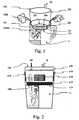
Fig. 1 is a perspective view of the coffee brewer positioned above a coffee mug that has a 7.2 cm top opening;Fig. 2 is a vertical sectional view of the coffee brewer positioned above a disposable standard 12 OZ paper cup that has 7.6 cm top opening;Fig. 3 is a vertical sectional view of the coffee brewer, showing filter paper peel-able semi circular polar and the 5 mm seal area;Fig. 4 is a top view of the coffee brewer;Fig. 5a is a bottom view of the coffee brewer;Fig. 5b is a bottom view of the coffee brewer with peel able half-perforation;Fig. 5c is a perspective view of the coffee brewer in a full height position on an accordion structured;Fig. 5d is a perspective view of the coffee brewer in a flattened position on an accordion structured;Fig 6 is a perspective view showing the bottom of the coffee brewer with Multiple Holes Cut Arrangement;Fig. 7 is a perspective view showing the bottom of the coffee brewer with One Single Cut Arrangement;Fig. 8 is a vertical sectional blow-up view of a pressure point created during filter paper stretched forming an arc;Fig. 9 is a perspective view of the ring support with three legs; andFig.10 is a perspective view of the filter cup son the supporting ring with three legs on top of a reservoir cup that has a greater than 8 cm top opening;- As best seen in
FIG. 1 and 2 , a drip-type coffee, or herbal or tea brewer apparatus comprises adisposable cup 10 which can be made from material include but is not limited to a group consisting of polystyrene compounds, plastic, organic and or non organic Bio-degradable polymer, and or modified and or unmodified organic fibers and or pulp and or starch and or coated paperboard and or a combination thereof. Referring to the cup, it is seen that it has a partialclosed bottom 110 that has an outer diameter about 7.3 cm andsidewalls 105 tapering outwardly towards the topopen mouth 103 that has an outer diameter about 8.5 cm. Thefilter cup 10 is constructed of a water permeable or porous material, preferablycommercial filter paper 121 which has substantial durability when it is in a wet condition, and which is coated with Polyethylene on one side and comparatively inexpensive so that it can be discarded after a single use. Thefilter paper 121 is attached to thebottom base 110 of thefilter cup 10 through heat seal or food grade starch or ultrasonic sealing system or supersonic sealing system. Thefilter cup 10 is designed with plurality number ofholes 108 on itsbottom base 110 as a time control mechanism which is fundamental to brew different kind of ingredients as each ingredient seems to be needed different time limit to be properly and correctly extracted. The area to be hot seal is as wide as around 5 mm along the rim of the circular shape of the filter paper. - Each
hole 108 of the invention represents 28.26 mm2. Although the size of the hole/cutting area 108 can be varied, this size is perfect to create natural water droplets size. The accumulation of the water on thepressure point 625 is turned into its maximum size before it starts to drop down as a droplet which falling into a range between 3mm in diameter to 8mm. The droplet size when reached to its maximum size does not change accordingly with the perforation change into a bigger size. Therefore to keep it in the maximum range of droplet size will become the most effective way to control drip down process in this type of filter brewer. This is one critical point that set apart this invention from the other inventions that has bigger or too small perforation outlet arrangement. Arrangement of the holes or cuttingareas 108 is designed to be separated at least 3 mm apart from each hole. This is important to create an individual droplet 630 (Fig.6 ) without interference from anotherdroplet 630 which is positioned too close to one and another, in order to maintain a standard dropping rate. As gravity draws down the liquid from top to bottom, all of the holes or cuttingareas 108 will get about the same force and release it at about the same rate. In other words, the hole/holes 108 receive about the same energy released from the gravity force or spread evenly to each and every hole108. The major benefit of this design is that it creates an independent and uniform size of droplets. As learned from trials, the more standard the dropping rate the more precise its function as a time controlling mechanism. Also the more output to release gravity force the faster it is in accommodating a faster brewing rate. - As best seen in the
Fig. 6 and Fig. 7 , apressure point 625 developed on each and every opening/cutting area when the hot water poured down on thefilter cup 10. The gravity force pushes down the hot water which in its natural way forms an arch shape that has the lowest point that we refer topressure point 625 on thefilter paper 121. There is a plurality ofpressure points 625 inFig.6 , while the embodiment ofFig. 7 has only one. Although bigger in cutting size,pressure point 625 inFig. 7 results in unstable andunpredictable droplets 630. On the other hand, the pressure point inFig.6 which resulted from multiple holes arrangement is more predictable and, as set forth in Table 1, proved to be more stable. - The heat seal area 109 (
Fig. 3 and Fig. 4 ) is applied at about a 5 mm width circling along the outer edge of thefilter paper 121 onto the cup'sbottom 110. The 5 mm heat seal width provides some stretching flexibility to form a better pressure point 625 (Fig. 8 ) during the droplets drip-down process. The hot seal is possible because thecommercial filter paper 121 contains Poly Ethylene on one of its sides. When subjected to heat, the PE material melts and become part of the cup assembly. - Furthermore, to ensure a resistant-free flow of the liquid from
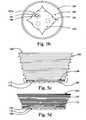
top filter cup 10 to the bottom of the reservoir cup, this invention provides a hot steam escaping route. Thefilter cup 10 provides four (4) hot steam escaping vents 201 (Fig. 1 andFig. 5a ) on its lower part of theouter sidewall 105. The accumulated hot steam has been a problem in brewing devices that are telescopingly assembled. The hot steam trapped in the lower liquid receiving cup has been one culprit of the slower extraction process. Throughout our trial using a perfectly fit telescoping assembly with no gap between the two cups, the trapped hot steam has accumulated into a massive force pushing up and thus delayed the drip down process. This indicates that the gravity force is not working in this condition as it is supposed to be. Therefore, releasing the trapped hot steam enables the liquid to flow from top to bottom in a resistant-free manner. The invention has four concave shapes vent 201 that are inwardly curving as deep as about 6 mm; as wide as about 1 cm and tapered upwardly as high as about 2.5 cm. Thus thevent 201 main functions are to avoid pressure build-up which can prolong the brewing time during brewing process in the reservoir mug. When disposed on a coffee mug thesevents 201 allowed hot steam that is accumulated on the reservoir cup to be escaped (Fig.1 ). The number of petal shape corner can be maximize or minimize accordingly to the desired output of hot steam released (HSR) rate. When viewed from bottom (Fig.5a ), thefilter cup 10 looked like flower with four petal shape. - The
filter cup 10 uses theleast filter paper 121 amongst any other similar product and is especially most efficient when compared to a tea bag for brewing tea beverage. Throughout our trial for brewing tea beverage, this invention embodiment that has six (6) holes arrangement resulted in about two minutes brewing time which is the same as that recommended in most tea bag brewing methods. For comparison, most tea bag requires 13.140mm2 (with a length of 146mm and width 90mm) of filter paper while this invention needs only 4183 mm2 (3.14 x 36.5mm x 36.5mm) filter paper that is 300% more efficient than most tea bag assemblies in using filter paper. Furthermore, in pursuing even more efficiency with highly precision machinery, an individual hole sealing system is possible to be applied. For example, eachindividual hole 108 with diameter of 5 mm needs only one circular filter paper with diameter of 7 mm to be entirely covered. With this fabricating method, one can save up to 75% of current use (4183.3mm2) and almost 1400% (13140 mm2 divided by 923 mm2) more efficient than most of the tea bag requirements in using filter paper. It is because its requirement offilter paper 121 can be adjusted accordingly to the number of cutting areas/holes and brewing time limit requirement. A six (6) holes arrangement needs only 922 mm2 of filter paper that can be tracked from the following calculation; 7 mm2 filter paper to be sealed into 6 cutting areas/holes that would equal to 3.14 x 7mm x 7mm = 154 mm2 x 6 holes = 923 mm2. Thus, with more flexible arrangements of the number of holes in order to accomplish a certain extraction need, thefilter cup 10 is not wasting anyunnecessary filter paper 121 like the other brewing methods. - When telescopically engaged into the mouth of the reservoir cup or
mug 11 that has a top inner side opening range between 7.2 cm in diameter to 7.5 cm in diameter, thefilter cup 10 will fit snuggly on the reservoir cup without any holder. For snugly sitting on top of the mug that has inner side top opening with diameter of 7.6 cm to 8 cm, thefilter cup 10 uses attachable thin (about 3 mm thick x 2.5 cm x 2 cm) rectangular shape polystyrene sheets 610 (Fig. 2 ) on the bottom part of the outer side of the cup. The number ofthin polystyrene sheets 610 can be used from one sheet to more than one according to the reservoir's cup top opening width. Thethin polystyrene sheet 610 can be pre-attached on thefilter cup 10 during fabrication or it can be provided with double-sided-tape and attached by user whenever needed. The telescopically engagement of the embodiment is the most practical way to hold the cup receptacle firmly with the reservoir cup and thus provide a unique coffee or tea disposable brewer "On the Go" for the portable public. - In addition to supporting the
filter cup 10 onto the reservoir cup ormug 11 that has a larger than 8 cm top opening, thefilter cup 10 uses perfectly fit sit-on-ring 233 (Fig. 9 and Fig. 10 ) which is rounded in shape and has three supportingjagged legs 238 that each has a length about 3.5 cm. Each of the supportinglegs 238 is positioned at about one third of the ring's circumference. Each of the supportinglegs 238 has a predetermine jagged part on itsbase 239 which is positioned to lock thefilter cup 10 onto the larger top opening of the reservoir cup during the brewing process. The material being used for this supporting sit-on-ring 233 can range from sturdy plastic, paper base, wooden, bamboo, or a composite of various metal substances. The supportingring 233 has awidth 235 of about 1 cm which is tapered outwardly which and further has atop diameter 236 of about 7.5cm and abottom diameter 237 of about 7.3cm. - In an alternative embodiment, the
filter cup 10 is constructed to include, but is not limited to, material such as plastic and or polymeric, where only the filter paper is to be peeled-off by pulling the semi circle 505 (Fig. 3 - 4 ) and discarded after each brewing cycle, thus preserving natural resources. The durability of this invention can also be prolonged to a further level of effectiveness and efficiency when the cup is made from, but is not limited to, material such as Poly Ethylene and or Poly Styrene or the combination thereof having a well know durability. With using these materials, the economic value of the cup itself will become very insignificant due to its capability to be used over and over again. The only part that is discarded throughout the brewing cycle is thefilter paper 121 that is easy to be recycled. This invention significantly promotes a clean environment through recycling only the part that is important to the brewing process and allowing the supporting material (the cup assembly 10) to be used again and again. The hot seal offilter paper 121 onto the paper, polystyrene, or polyethylene cup is easily done. A simple tool like solder that is inexpensive and considered as an average household tool can be modified into a food grade (stainless steel) heating tip and used to seal thefilter paper 121 onto thebottom 110 of thefilter cup 10. Another alternative is to use a same shape and size of HVS paper or protection material commonly used in ironing to prevent the conventional solder from directly touching thefilter paper 121. The filter paper is seal-able because it contains Poly Ethylene on one of its sides. When applied to heat, Poly Ethylene melts and attaches to the bottom of the cup and becomes part of the cup. As one brewing is done, the cup is reusable. All it needs is to be thoroughly and properly washed and rinsed. The filter paper has been cut in circular shape with two predetermined semi circles 505 on each of its poles (Fig. 3-4 ) that is used to ease the peeling off process of thefilter paper 121 after washing. It is easier to peel off thefilter paper 121 when it is wet. After drying, a new filter paper is ready to be sealed onto the cup which creates another reusable new brewing device. - A standard coated paper cup, unless punctured, is encapsulated by a thin layer of Polyethylene substances to prevent any non-food grade material contained in the paper itself from contaminating the beverage contained into the cup. Therefore, in one alternative, especially for the coated paper cup, there is a process of re-coating the punched perforation inner side wall with water proof and heat resistant material such as polyethylene including, but are not limited to, any kinds of food grade wax, resin, organic or synthetic polymer, modified or unmodified sugar base coat-able substances. The method of re-coating includes but is not limited to brush, spray, and or immersion.
- A further alternative to avoid a recoating process after puncturing the
perforation 108 on the paper cup'sbase 110 is to change the paper cup's base 110 material to material including, but not limited to, polystyrene, biodegradable substances such as modified and or unmodified organic fibers and or pulp and or starch and or polyethylene. During fabrication, the cup's base 110 made of polystyrene and or biodegradable substances and or polyethylene is fed into the paper cup forming machine to be integrated into a new combination of cup that has a paper coatedwall 105 and polyethylene and or biodegradable substances and orpolystyrene bottom base 110. With this combination, the need to coat theperforation 108 is eliminated because the material being used is food grade. One more benefit is that the new combination cup reduces the need to punch theperforation 108 during fabrication. This is because theperforation 108, made with material such as polyethylene and or polystyrene, is formed in a mold that has a predetermined number of perforations during forming the cup'sbase 110. - Another alternative for making the cup's
perforation 108 very flexible to be used in any type of extraction, is to form a maximum number of half-perforations 107 (Fig. 5b ) allowed on the bottom of the cup'sbase 110. The perforation is formed into ahalf cut 107 with a small part 107a. (about one fifth of its total base area) bulging out from the filter cup's base 110 to allow easy pull-off or peel-off when necessary by one in preparing a specific need of brewing. The half cut 107 is structured with many small-cut-and-gaps along the outer edge of the perforation but does not puncture it loose from the filter cup'sbase 110. Although some small leaking may appear from the un-peeled perforation, this method allows a user to custom peel-off any number of perforations he/she desires in order to perform his/her specific brewing need. - Further still alternatively, to save rack space on the retailer shelf and to provide a single pack of filter cup + coffee/tea + sugar + creamer into one single sachet, the
filter cup 10 may be formed into an accordion like structure. The accordion shape or structure (best seen onFig. 5c and Fig.5d ) of the cup can be formed during fabrication by using a specific molding treatment and or heat treatment and or pressure forming or the combination thereof directly or indirectly influenced in all or in part of the filter cup'swall 105. The accordion shape or structure of thefilter cup 10 can allow the cup to shorten or flatten (Fig. 5d ) and thus can be fitted into a single serving pack. When the pack is opened, one can easily pull the flattened cup into a regular height (Fig. 5c ) filter cup without altering the cup's main function as a filter apparatus. - In carrying out the operation of the invention, presumably the
filter cup 10 has been assembled in the manner described and illustrated, and is supported on top of the mug. As seen inFig. 1 , a small pre-mix sachet that contained about 25 grams ofground coffee 612 plus sugar plus powder creamer is opened and poured onto thefilter cup 10. When the hot water reaches a suitable degree, the hot water is then poured into thefilter cup 10 and fills the cup almost to thetop opening 103. The drip down process starts immediately but still provides enough time to do the stirring movement on the mixture. A back and forth stirring movement of about 30 seconds to one minute is required when the hot water is fully filled in thefilter cup 10. A proper stirring movement is crucial to break the shield effect of the fat layer created when in contact with the hot water. When the stirring process is done, the user only needs to wait until the mixed beverage has dripped down entirely onto the coffee mug. Furthermore, thefilter paper 121 has trapped all the unextractable ingredients on the assembly of thefilter cup 10. The beverage brewed in thefilter cup 10 seeps through the filter paper, drips down the other side thereof into the mug. Once the water level is low and the drip down process is considered slow on thefilter cup 10, thefilter cup 10 can be easily pulled out and discarded. Instantly, the coffee beverage can then be consumed. - It is emphasized that the
filter cup 10 can accommodate a reasonable volume (160 ml) of hot water required for brewing one serving of coffee or tea beverage (which usually only requires about 150 ml) on one single pouring. Moreover, thefilter cup 10 is designed to provide easiness on the pouring effort even on the larger cup with at most two simple pourings. There is no need to pour a small volume and then wait and then repeatedly do the same thing until the beverage is ready to consume, like some existing brewing methods that use filter elements. - It is also emphasized that the arrangement of the holes/cutting
areas 108 on thebottom base 110 of thefilter cup 10 can be arranged by the plurality of outlets to result in a drip time in a range of about 1 minute to 13 minutes or longer depending on the specific need of brewing ingredient and time. The size of the hole/cutting area can be also modified into larger or smaller sizes to satisfy with a specific brewing requirement. The shape of the opening or cutting area can be differentiated into many forms (such as company logo; characters; company's Icon or the like) as to make it fancier and enhanced its aesthetic appearances. - The specifics of the invention described before mentioned will be understood as an illustration purpose and example embodiments purpose to the invention. Numerous modifications and alterations are within the competency for a person skilled in the art to employ the shown embodiment utilizing functionally equivalent components to those shown and described, without departing from the scope of the invention. For example, the shape and volume of the cup receptacle can be varied. Furthermore, the appearance of the hot steam escaping vent and the cup receptacle can also be varied to most any diameter desired. The scope of the invention, however, encompasses larger versions of the apparatus adapted for making more than one cup of coffee at the time. In addition, the scope of the invention includes use of non-disposable materials. All such modifications are intended to be included within the scope of the invention as defined by the appended claims.
- When the coffee brewer shown and described is adapted for preparing an individual serving of coffee or tea or the like, the
filter cup 10 may be approximately 4.7 cm high and have an open upper surface approximately 8.5 cm in diameter and a lower partially open bottom 7.3 cm in diameter. - Complete List of Numerals of Elements:
- HSR
- Hot Steam Released
- HSBU
- Hot Steam Build Up
- GF
- Gravity Force
- 10
- disposable cup
- 11
- reservoir cup or mug
- 110
- partial closed bottom
- 105
- outer sidewalls
- 103
- top open mouth
- 201
- hot steam concave shape vents
- 121
- filter paper
- 108
- holes or cutting areas
- 625
- pressure point
- 630
- liquid droplets
- 109
- heat seal area
- 610
- polystyrene sheets
- 612
- Coffee ground
- 233
- perfectly fit sit-on-ring
- 238
- supporting jagged legs
- 239
- jagged part of supporting leg
- 233
- supporting ring
- 235
- width of supporting sit-on-ring
- 236
- top diameter of supporting sit-on-ring
- 237
- bottom diameter of supporting sit-on-ring
- 505
- peel-able semi circle
- 107
- half-perforations
- 107a.
- a small bulging part to peel half perforation
Claims (18)
- A beverage brewer, adapted to discharge fresh extractable ingredients to a liquid receiving container (11) comprising:- a disposable brewing cup (10) having an open top (103) and a liquid pervious bottom (110).- one sheet of filter element (121) on the bottom (110) surface,- perforations (108) in the bottom (110) adapted to create water droplets of natural size,- At least one concave shape vent (201) disposed on a lower part of the brewing cup (10),characterized in that- the filter element (121) is sealed along at least 1 mm with to a rim (109) of the bottom (110) of the brewing cup (10) by a non-toxic meltable substance contained within the filter element (121),- at least one vent-providing polysterene sheet (610) is provided positionable on the lower part of the brewing cup (10) and- a sit-on-ring is provided comprising a tapered annular shape ring (233) and three jagged supporting legs (238) for supporting the brewing cup (10) on the liquid receiving container (11).
- The device as set forth in claim 1 wherein said brewing cup normally employs a certain standard quantity of liquid and a certain standard quantity of extractable ingredient to yield a standard volume of beverage.
- The device as set forth in claim 1 wherein said brewing cup (10) is fabricated from a material selected from a group consisting of polystyrene compounds, plastic, organic Bio-degradable polymer, non organic polymer, modified and unmodified organic fibers and or pulp and or starch and coated paperboard.
- The device as set forth in claim 1 wherein said brewing cup (10) is fabricated from a combination of material selected from a group consisting of polystyrene compounds, plastic, organic and/or non organic Bio- degradable polymer, and/or modified and/or unmodified organic fibers and/or pulp and/or starch and coated paperboard.
- The device as set forth in claim 1 wherein said sealing method of said filter paper (121) is to provide a stretching flexibility required to form a sufficient arc on pressure points (625).
- The device as set forth in claim 1 wherein said perforation (108) is structured to be adapted to about the maximum size of the water droplet (630) when applies in a similar brewing cup with the similar water volume and gravity force.
- The device as set forth in claim 1 wherein said lower wall of said brewing cup (10) is circular in cross section.
- The device as set forth in claim 1 wherein said brewing cup (10) is adapted to receive a supply of liquid and is liquid permeable throughout the perforation (108).
- The device as set forth in claim 1 wherein said perforations (108) are arranged at least one millimeter apart from one to another.
- The device as set forth in claim 1 wherein each of said perforation (108) has an area of about 28.26 millimeters square.
- The device as set forth in claim 1 wherein said filter element (121) is heat-sealed over an area as wide as about five millimeters circling along the outer edge unto the bottom (110) base of said brewing cup (10).
- The device as set forth in claim 1 wherein said vent (201) is arranged on the brewing cup lower part of the outer sidewall.
- The device as set forth in claim 12 wherein said vents (201) are spaced equally unto four cross sectional sides of the brewing cup (10).
- The device as set forth in claim 12 wherein said vent (201) comprises an inwardly concaved corner as deep as six millimeters, and as wide as one centimeter that tapers upwardly as high as two and half centimeters of said brewing cup outer wall (105).
- The device as set forth in claim 1 wherein said vent-providing polystyrene sheet (610) is attachable unto said bottom part of the outer side of the brewing cup (10)
- The device as set forth in claim 15 wherein said vent-providing polystyrene sheet (610) is rectangular in shape with an approximate three millimeter thickness, a length of about two and half centimeters, and a width of about two centimeters.
- The device as set forth in claim 1 wherein said supporting sit-on-ring (233) is annular in shape, said supporting sit-on-ring being telescopically adapted unto the lower portion of said brewing cup (10) for supporting said brewing cup (10) above the liquid receiving container (11), upper portions of said supporting sit-on-ring (233) are tapered downwardly, are arranged with a width of 1 cm tapered outwardly which has top diameter of 7.5 cm and bottom diameter of 7.3 cm.
- The device as set forth in claim 17 wherein said supporting legs (238) are positionable unto the top of said reservoir cup (11), and include a jagged locking part (239) extending therefrom to engage unto the top opening of said reservoir cup (11) and thereby retain said brewing cup (10) in place at a fixed orientation within said liquid receiving container (11).
Applications Claiming Priority (3)
| Application Number | Priority Date | Filing Date | Title |
|---|---|---|---|
| US92639307P | 2007-04-25 | 2007-04-25 | |
| ID20070546 | 2007-10-01 | ||
| PCT/ID2008/000002WO2008132705A1 (en) | 2007-04-25 | 2008-02-25 | Instant extraction cup |
Publications (2)
| Publication Number | Publication Date |
|---|---|
| EP2190325A1 EP2190325A1 (en) | 2010-06-02 |
| EP2190325B1true EP2190325B1 (en) | 2011-04-13 |
Family
ID=39885460
Family Applications (1)
| Application Number | Title | Priority Date | Filing Date |
|---|---|---|---|
| EP08738130AActiveEP2190325B1 (en) | 2007-04-25 | 2008-02-25 | Instant extraction cup |
Country Status (6)
| Country | Link |
|---|---|
| US (2) | US7856922B2 (en) |
| EP (1) | EP2190325B1 (en) |
| CN (1) | CN101686769A (en) |
| AT (1) | ATE505118T1 (en) |
| DE (1) | DE602008006214D1 (en) |
| WO (1) | WO2008132705A1 (en) |
Families Citing this family (27)
| Publication number | Priority date | Publication date | Assignee | Title |
|---|---|---|---|---|
| TWI401052B (en)* | 2007-04-25 | 2013-07-11 | Tjen Eddy | Beverage brewing device |
| US8043645B2 (en) | 2008-07-09 | 2011-10-25 | Starbucks Corporation | Method of making beverages with enhanced flavors and aromas |
| BRPI0923895A2 (en)* | 2009-01-02 | 2015-07-28 | Ethical Coffee Company Sa | Capsule for the preparation of a drink and device |
| WO2010111563A1 (en)* | 2009-03-27 | 2010-09-30 | The Procter & Gamble Company | Droplet forming fluid treatment devices and methods of forming filtered droplets in a fluid treatment device |
| IT1393999B1 (en)* | 2009-04-01 | 2012-05-17 | Rancilio Macchine Caffe | MACHINE FOR THE PREPARATION OF INFUSES, ESPRESSO IN PARTICULAR COFFEE, DISPENSER GROUP AND METHOD OF REALIZING THE SAME |
| TWM369718U (en)* | 2009-07-17 | 2009-12-01 | Pegatron Corp | Disposable tea set and tea pot thereof |
| US20110192750A1 (en)* | 2009-10-14 | 2011-08-11 | Sector Labs | Room For System |
| DE102010031842A1 (en)* | 2010-07-22 | 2012-01-26 | Rt-Filtertechnik Gmbh | Filter element for filtration of fluids |
| US20120073448A1 (en)* | 2010-09-23 | 2012-03-29 | Husted Royce Hill | Coffee maker with computerized steeping control |
| US20130019754A1 (en)* | 2011-07-22 | 2013-01-24 | Pao-Wu Tien | Brewing device with leak-proof structure |
| US10450130B2 (en)* | 2012-09-12 | 2019-10-22 | Kraft Foods R & D, Inc. | Cartridges, systems and methods for preparation of beverages |
| US8906436B2 (en) | 2013-03-15 | 2014-12-09 | Ptc-Innovations, Llc | Single serve beverage additive cartridge |
| US10278534B2 (en)* | 2013-12-01 | 2019-05-07 | Fellow Industries Inc. | Beverage steeping and dispensing system |
| TWI568394B (en) | 2015-07-20 | 2017-02-01 | 吉諾工業有限公司 | Drink brewing device |
| CN106361148B (en)* | 2015-07-23 | 2019-10-29 | 吉诺工业有限公司 | Beverage brewing device |
| KR102071046B1 (en)* | 2018-02-05 | 2020-01-28 | 주식회사 이노디자인 | Dripper and portable coffee drinking tumbler |
| EP3764850A1 (en)* | 2018-03-14 | 2021-01-20 | Société des Produits Nestlé S.A. | Beverage machine with a non-homogeneous ingredient extraction configuration |
| US10595663B2 (en)* | 2018-05-10 | 2020-03-24 | Reginald Osagie Akpata | Edo cup 2.0 |
| WO2020087095A1 (en)* | 2018-10-26 | 2020-04-30 | Ly Ngoc Minh | Brewing tool set with pressure regulating function |
| CN110101308A (en)* | 2019-05-27 | 2019-08-09 | 冯磊 | A kind of parameter determination method limiting the tealeaves filter bowl of flow, tea set and the filter bowl |
| CN110150979B (en)* | 2019-05-31 | 2021-09-14 | 艾迪·田 | Beverage brewing device |
| USD953801S1 (en) | 2019-08-19 | 2022-06-07 | Espro, Inc. | Pour over brewing device |
| US11583130B2 (en)* | 2019-10-18 | 2023-02-21 | Timothy Arthur Bindon | Beverage brewing assembly |
| USD929804S1 (en) | 2019-12-02 | 2021-09-07 | Espro, Inc. | Filter element |
| DE102020104079B3 (en)* | 2020-02-17 | 2021-01-21 | Wolfgang Muckenhuber | Filter vessel, device and method for producing a filtrate |
| BE1028065B1 (en)* | 2020-02-18 | 2021-09-15 | Koffie F Rombouts | Filter for the preparation of coffee or infusion |
| CN112129072B (en)* | 2020-09-21 | 2021-11-23 | 大连交通大学 | Device and method for recycling coffee grounds |
Family Cites Families (33)
| Publication number | Priority date | Publication date | Assignee | Title |
|---|---|---|---|---|
| US7490542B2 (en)* | 1920-02-11 | 2009-02-17 | I.T.A.Ca S.R.L. | Cartridge for coffee and soluble products and relative method of producing a beverage and apparatus for extracting a beverage |
| US2329608A (en)* | 1941-02-10 | 1943-09-14 | Graham | Tea making apparatus |
| FR914538A (en)* | 1945-09-17 | 1946-10-10 | Coffee maker | |
| US2607338A (en)* | 1950-04-04 | 1952-08-19 | Fred L Parenti | Juice catcher for cooking utensils |
| US2885290A (en)* | 1955-12-19 | 1959-05-05 | Krasker Abraham | Instantaneous coffee beverage |
| US3252403A (en)* | 1962-10-19 | 1966-05-24 | Polizzi Anthony Charles | Coffee filter |
| US3270658A (en)* | 1963-10-09 | 1966-09-06 | Tavera Antonio | Coffee maker |
| US3985069A (en)* | 1973-12-03 | 1976-10-12 | Cavalluzzi Frank J | Coffee beverage drip brewer |
| US4069751A (en)* | 1977-01-10 | 1978-01-24 | Sunbeam Corporation | Coffee brewing apparatus |
| US4174659A (en)* | 1977-11-14 | 1979-11-20 | Econo-Brew, Inc. | Coffee brewer |
| US4158329A (en)* | 1978-04-24 | 1979-06-19 | Mcknight Robert J | Drip coffee brewer |
| US5036755A (en)* | 1980-05-27 | 1991-08-06 | Abdenour Joseph D | Brewing improvement |
| US4446158A (en)* | 1982-06-08 | 1984-05-01 | English Philip H | Apparatus for making individual beverage quantities |
| US4520716A (en)* | 1984-03-19 | 1985-06-04 | Hayes Susan M | Drip-type coffee making apparatus |
| US4577080A (en)* | 1985-03-19 | 1986-03-18 | Gee Associates | Coffee maker adapted for use in a microwave oven |
| US4739697A (en)* | 1987-05-04 | 1988-04-26 | Bloomfield Industries, Inc. | Brew chamber with filter spacer |
| US4867880A (en)* | 1988-10-14 | 1989-09-19 | D.J. Incorporated | Brewing device |
| US4908222A (en)* | 1989-02-16 | 1990-03-13 | Dong Yu | Microwave brewing apparatus and method |
| US5064980A (en)* | 1990-06-11 | 1991-11-12 | Gee Associates | Coffee maker |
| US5010221A (en)* | 1990-06-11 | 1991-04-23 | Gee Associates | Microwaveable coffee makers |
| US5243164A (en)* | 1990-12-14 | 1993-09-07 | Gee Associates | Beverage maker |
| CA2184298C (en)* | 1996-08-27 | 1998-08-18 | Yvan St-Gelais | Permanent filter coffeemaker |
| US5632194A (en)* | 1996-10-30 | 1997-05-27 | Lin; Yu-Mei | Infusion maker |
| US6327084B1 (en)* | 1997-06-30 | 2001-12-04 | Central Glass Company, Limited | Display system where polarized light impinges on platelike laminate at brewster's angle or emerges therefrom at angle equal thereto |
| WO2000018657A1 (en)* | 1998-09-30 | 2000-04-06 | Nissin Shokuhin Kabushiki Kaisha | Food container lid member_______________________________________ |
| JP2001275842A (en)* | 2000-03-30 | 2001-10-09 | Tatsuo Ikoma | Functional filter, method of manufacturing the same, and brewing device using the same |
| US6443573B2 (en)* | 2000-08-10 | 2002-09-03 | Yazaki Corporation | On-vehicle display unit |
| AU735073B3 (en)* | 2000-10-11 | 2001-06-28 | Nick O'loughlin | Cup plunger |
| WO2003065858A1 (en)* | 2002-02-08 | 2003-08-14 | Farnge Co., Ltd. | Functional filter, method for manufacturing the filter, and extracting device using the filter |
| US6889599B2 (en)* | 2002-04-16 | 2005-05-10 | Koslow Technologies Corporation | Brewing apparatus and method |
| US7258450B2 (en)* | 2003-12-04 | 2007-08-21 | Sharp Kabushiki Kaisha | Projector optical system configuration, optical module, and projector, and also electronic equipment, vehicle, projection system, and showcase utilizing such projector |
| US7131728B2 (en)* | 2003-12-31 | 2006-11-07 | Symbol Technologies, Inc. | Method and apparatus for displaying information in automotive application using a laser projection display |
| US7175321B1 (en)* | 2004-03-24 | 2007-02-13 | Lopez Gustavo M | Projector systems |
- 2007
- 2007-11-30USUS11/947,901patent/US7856922B2/ennot_activeExpired - Fee Related
- 2008
- 2008-02-25WOPCT/ID2008/000002patent/WO2008132705A1/enactiveApplication Filing
- 2008-02-25ATAT08738130Tpatent/ATE505118T1/ennot_activeIP Right Cessation
- 2008-02-25DEDE602008006214Tpatent/DE602008006214D1/enactiveActive
- 2008-02-25EPEP08738130Apatent/EP2190325B1/enactiveActive
- 2008-02-25CNCN200880021249Apatent/CN101686769A/enactivePending
- 2008-04-04USUS12/098,137patent/US20090027621A1/ennot_activeAbandoned
Also Published As
| Publication number | Publication date |
|---|---|
| CN101686769A (en) | 2010-03-31 |
| EP2190325A1 (en) | 2010-06-02 |
| US20090027621A1 (en) | 2009-01-29 |
| ATE505118T1 (en) | 2011-04-15 |
| US20080264268A1 (en) | 2008-10-30 |
| WO2008132705A1 (en) | 2008-11-06 |
| DE602008006214D1 (en) | 2011-05-26 |
| US7856922B2 (en) | 2010-12-28 |
Similar Documents
| Publication | Publication Date | Title |
|---|---|---|
| EP2190325B1 (en) | Instant extraction cup | |
| CN102958408B (en) | For the method for beverage brewed with comprise can the storage box of soak-out material | |
| EP1594763B1 (en) | A capsule to be used to prepare an infused beverage | |
| US6007853A (en) | Disposable beverage infuser | |
| US4158329A (en) | Drip coffee brewer | |
| CN1099267C (en) | Infuser unit for making beverages | |
| US8012523B2 (en) | Permanent filtering pod for brewing beverages | |
| US20040020368A1 (en) | Device and method for brewing coffee & espresso beverages | |
| US20050160918A1 (en) | Apparatus for making brewed coffee and the like | |
| WO2005076698A2 (en) | Brewing filter apparatus | |
| ES2928102T3 (en) | Steeping apparatus and methods for preparing a drink | |
| EP1513741B1 (en) | Filter for extraction device | |
| US3095801A (en) | Beverage percolating apparatus with unit dry beverage container | |
| US3357340A (en) | Coffee brewing apparatus | |
| CN110150979B (en) | Beverage brewing device | |
| WO2017160778A1 (en) | Infusion apparatus for preparing a beverage | |
| CN210300666U (en) | Beverage brewing device | |
| JP3673944B2 (en) | How to make tea | |
| TWI401052B (en) | Beverage brewing device | |
| WO2006052257A1 (en) | Apparatus for making brewed coffee and the like | |
| KR200418154Y1 (en) | Tea ceremony with integral strainer | |
| JP5994046B2 (en) | Tea bag with lid for tea bag | |
| KR102733953B1 (en) | a portable coffee maker | |
| JP2015173676A (en) | Teapot with lid for tea bag | |
| GB2384689A (en) | Infusion device for beverage making |
Legal Events
| Date | Code | Title | Description |
|---|---|---|---|
| PUAI | Public reference made under article 153(3) epc to a published international application that has entered the european phase | Free format text:ORIGINAL CODE: 0009012 | |
| 17P | Request for examination filed | Effective date:20100324 | |
| AK | Designated contracting states | Kind code of ref document:A1 Designated state(s):AT BE BG CH CY CZ DE DK EE ES FI FR GB GR HR HU IE IS IT LI LT LU LV MC MT NL NO PL PT RO SE SI SK TR | |
| AX | Request for extension of the european patent | Extension state:AL BA MK RS | |
| DAX | Request for extension of the european patent (deleted) | ||
| GRAP | Despatch of communication of intention to grant a patent | Free format text:ORIGINAL CODE: EPIDOSNIGR1 | |
| GRAS | Grant fee paid | Free format text:ORIGINAL CODE: EPIDOSNIGR3 | |
| GRAA | (expected) grant | Free format text:ORIGINAL CODE: 0009210 | |
| AK | Designated contracting states | Kind code of ref document:B1 Designated state(s):AT BE BG CH CY CZ DE DK EE ES FI FR GB GR HR HU IE IS IT LI LT LU LV MC MT NL NO PL PT RO SE SI SK TR | |
| REG | Reference to a national code | Ref country code:GB Ref legal event code:FG4D | |
| REG | Reference to a national code | Ref country code:CH Ref legal event code:EP | |
| REG | Reference to a national code | Ref country code:IE Ref legal event code:FG4D | |
| REF | Corresponds to: | Ref document number:602008006214 Country of ref document:DE Date of ref document:20110526 Kind code of ref document:P | |
| REG | Reference to a national code | Ref country code:DE Ref legal event code:R096 Ref document number:602008006214 Country of ref document:DE Effective date:20110526 | |
| REG | Reference to a national code | Ref country code:NL Ref legal event code:VDEP Effective date:20110413 | |
| LTIE | Lt: invalidation of european patent or patent extension | Effective date:20110413 | |
| PG25 | Lapsed in a contracting state [announced via postgrant information from national office to epo] | Ref country code:SE Free format text:LAPSE BECAUSE OF FAILURE TO SUBMIT A TRANSLATION OF THE DESCRIPTION OR TO PAY THE FEE WITHIN THE PRESCRIBED TIME-LIMIT Effective date:20110413 Ref country code:HR Free format text:LAPSE BECAUSE OF FAILURE TO SUBMIT A TRANSLATION OF THE DESCRIPTION OR TO PAY THE FEE WITHIN THE PRESCRIBED TIME-LIMIT Effective date:20110413 Ref country code:NO Free format text:LAPSE BECAUSE OF FAILURE TO SUBMIT A TRANSLATION OF THE DESCRIPTION OR TO PAY THE FEE WITHIN THE PRESCRIBED TIME-LIMIT Effective date:20110713 Ref country code:PT Free format text:LAPSE BECAUSE OF FAILURE TO SUBMIT A TRANSLATION OF THE DESCRIPTION OR TO PAY THE FEE WITHIN THE PRESCRIBED TIME-LIMIT Effective date:20110816 Ref country code:LT Free format text:LAPSE BECAUSE OF FAILURE TO SUBMIT A TRANSLATION OF THE DESCRIPTION OR TO PAY THE FEE WITHIN THE PRESCRIBED TIME-LIMIT Effective date:20110413 | |
| PG25 | Lapsed in a contracting state [announced via postgrant information from national office to epo] | Ref country code:ES Free format text:LAPSE BECAUSE OF FAILURE TO SUBMIT A TRANSLATION OF THE DESCRIPTION OR TO PAY THE FEE WITHIN THE PRESCRIBED TIME-LIMIT Effective date:20110724 Ref country code:IS Free format text:LAPSE BECAUSE OF FAILURE TO SUBMIT A TRANSLATION OF THE DESCRIPTION OR TO PAY THE FEE WITHIN THE PRESCRIBED TIME-LIMIT Effective date:20110813 Ref country code:CY Free format text:LAPSE BECAUSE OF FAILURE TO SUBMIT A TRANSLATION OF THE DESCRIPTION OR TO PAY THE FEE WITHIN THE PRESCRIBED TIME-LIMIT Effective date:20110413 Ref country code:FI Free format text:LAPSE BECAUSE OF FAILURE TO SUBMIT A TRANSLATION OF THE DESCRIPTION OR TO PAY THE FEE WITHIN THE PRESCRIBED TIME-LIMIT Effective date:20110413 Ref country code:BE Free format text:LAPSE BECAUSE OF FAILURE TO SUBMIT A TRANSLATION OF THE DESCRIPTION OR TO PAY THE FEE WITHIN THE PRESCRIBED TIME-LIMIT Effective date:20110413 Ref country code:LV Free format text:LAPSE BECAUSE OF FAILURE TO SUBMIT A TRANSLATION OF THE DESCRIPTION OR TO PAY THE FEE WITHIN THE PRESCRIBED TIME-LIMIT Effective date:20110413 Ref country code:AT Free format text:LAPSE BECAUSE OF FAILURE TO SUBMIT A TRANSLATION OF THE DESCRIPTION OR TO PAY THE FEE WITHIN THE PRESCRIBED TIME-LIMIT Effective date:20110413 Ref country code:GR Free format text:LAPSE BECAUSE OF FAILURE TO SUBMIT A TRANSLATION OF THE DESCRIPTION OR TO PAY THE FEE WITHIN THE PRESCRIBED TIME-LIMIT Effective date:20110714 Ref country code:SI Free format text:LAPSE BECAUSE OF FAILURE TO SUBMIT A TRANSLATION OF THE DESCRIPTION OR TO PAY THE FEE WITHIN THE PRESCRIBED TIME-LIMIT Effective date:20110413 | |
| PG25 | Lapsed in a contracting state [announced via postgrant information from national office to epo] | Ref country code:NL Free format text:LAPSE BECAUSE OF FAILURE TO SUBMIT A TRANSLATION OF THE DESCRIPTION OR TO PAY THE FEE WITHIN THE PRESCRIBED TIME-LIMIT Effective date:20110413 | |
| PG25 | Lapsed in a contracting state [announced via postgrant information from national office to epo] | Ref country code:EE Free format text:LAPSE BECAUSE OF FAILURE TO SUBMIT A TRANSLATION OF THE DESCRIPTION OR TO PAY THE FEE WITHIN THE PRESCRIBED TIME-LIMIT Effective date:20110413 Ref country code:CZ Free format text:LAPSE BECAUSE OF FAILURE TO SUBMIT A TRANSLATION OF THE DESCRIPTION OR TO PAY THE FEE WITHIN THE PRESCRIBED TIME-LIMIT Effective date:20110413 | |
| PLBE | No opposition filed within time limit | Free format text:ORIGINAL CODE: 0009261 | |
| STAA | Information on the status of an ep patent application or granted ep patent | Free format text:STATUS: NO OPPOSITION FILED WITHIN TIME LIMIT | |
| PG25 | Lapsed in a contracting state [announced via postgrant information from national office to epo] | Ref country code:RO Free format text:LAPSE BECAUSE OF FAILURE TO SUBMIT A TRANSLATION OF THE DESCRIPTION OR TO PAY THE FEE WITHIN THE PRESCRIBED TIME-LIMIT Effective date:20110413 Ref country code:SK Free format text:LAPSE BECAUSE OF FAILURE TO SUBMIT A TRANSLATION OF THE DESCRIPTION OR TO PAY THE FEE WITHIN THE PRESCRIBED TIME-LIMIT Effective date:20110413 Ref country code:DK Free format text:LAPSE BECAUSE OF FAILURE TO SUBMIT A TRANSLATION OF THE DESCRIPTION OR TO PAY THE FEE WITHIN THE PRESCRIBED TIME-LIMIT Effective date:20110413 Ref country code:PL Free format text:LAPSE BECAUSE OF FAILURE TO SUBMIT A TRANSLATION OF THE DESCRIPTION OR TO PAY THE FEE WITHIN THE PRESCRIBED TIME-LIMIT Effective date:20110413 | |
| 26N | No opposition filed | Effective date:20120116 | |
| REG | Reference to a national code | Ref country code:DE Ref legal event code:R097 Ref document number:602008006214 Country of ref document:DE Effective date:20120116 | |
| PG25 | Lapsed in a contracting state [announced via postgrant information from national office to epo] | Ref country code:IT Free format text:LAPSE BECAUSE OF FAILURE TO SUBMIT A TRANSLATION OF THE DESCRIPTION OR TO PAY THE FEE WITHIN THE PRESCRIBED TIME-LIMIT Effective date:20110413 | |
| PG25 | Lapsed in a contracting state [announced via postgrant information from national office to epo] | Ref country code:MC Free format text:LAPSE BECAUSE OF NON-PAYMENT OF DUE FEES Effective date:20120229 | |
| GBPC | Gb: european patent ceased through non-payment of renewal fee | Effective date:20120225 | |
| REG | Reference to a national code | Ref country code:IE Ref legal event code:MM4A | |
| PG25 | Lapsed in a contracting state [announced via postgrant information from national office to epo] | Ref country code:IE Free format text:LAPSE BECAUSE OF NON-PAYMENT OF DUE FEES Effective date:20120225 Ref country code:GB Free format text:LAPSE BECAUSE OF NON-PAYMENT OF DUE FEES Effective date:20120225 | |
| PG25 | Lapsed in a contracting state [announced via postgrant information from national office to epo] | Ref country code:BG Free format text:LAPSE BECAUSE OF FAILURE TO SUBMIT A TRANSLATION OF THE DESCRIPTION OR TO PAY THE FEE WITHIN THE PRESCRIBED TIME-LIMIT Effective date:20110713 | |
| PG25 | Lapsed in a contracting state [announced via postgrant information from national office to epo] | Ref country code:MT Free format text:LAPSE BECAUSE OF FAILURE TO SUBMIT A TRANSLATION OF THE DESCRIPTION OR TO PAY THE FEE WITHIN THE PRESCRIBED TIME-LIMIT Effective date:20110413 | |
| PG25 | Lapsed in a contracting state [announced via postgrant information from national office to epo] | Ref country code:TR Free format text:LAPSE BECAUSE OF FAILURE TO SUBMIT A TRANSLATION OF THE DESCRIPTION OR TO PAY THE FEE WITHIN THE PRESCRIBED TIME-LIMIT Effective date:20110413 | |
| PG25 | Lapsed in a contracting state [announced via postgrant information from national office to epo] | Ref country code:LU Free format text:LAPSE BECAUSE OF NON-PAYMENT OF DUE FEES Effective date:20120225 | |
| PG25 | Lapsed in a contracting state [announced via postgrant information from national office to epo] | Ref country code:HU Free format text:LAPSE BECAUSE OF FAILURE TO SUBMIT A TRANSLATION OF THE DESCRIPTION OR TO PAY THE FEE WITHIN THE PRESCRIBED TIME-LIMIT Effective date:20080225 | |
| REG | Reference to a national code | Ref country code:FR Ref legal event code:PLFP Year of fee payment:9 | |
| REG | Reference to a national code | Ref country code:FR Ref legal event code:PLFP Year of fee payment:10 | |
| REG | Reference to a national code | Ref country code:FR Ref legal event code:PLFP Year of fee payment:11 | |
| PGFP | Annual fee paid to national office [announced via postgrant information from national office to epo] | Ref country code:CH Payment date:20230307 Year of fee payment:16 | |
| REG | Reference to a national code | Ref country code:CH Ref legal event code:PL | |
| PGFP | Annual fee paid to national office [announced via postgrant information from national office to epo] | Ref country code:DE Payment date:20240902 Year of fee payment:17 | |
| PGFP | Annual fee paid to national office [announced via postgrant information from national office to epo] | Ref country code:FR Payment date:20240902 Year of fee payment:17 | |
| PG25 | Lapsed in a contracting state [announced via postgrant information from national office to epo] | Ref country code:CH Free format text:LAPSE BECAUSE OF NON-PAYMENT OF DUE FEES Effective date:20240229 | |
| PG25 | Lapsed in a contracting state [announced via postgrant information from national office to epo] | Ref country code:CH Free format text:LAPSE BECAUSE OF NON-PAYMENT OF DUE FEES Effective date:20240229 |