EP2186465B1 - Self-contained sterilizable surgical system - Google Patents
Self-contained sterilizable surgical systemDownload PDFInfo
- Publication number
- EP2186465B1 EP2186465B1EP09014665AEP09014665AEP2186465B1EP 2186465 B1EP2186465 B1EP 2186465B1EP 09014665 AEP09014665 AEP 09014665AEP 09014665 AEP09014665 AEP 09014665AEP 2186465 B1EP2186465 B1EP 2186465B1
- Authority
- EP
- European Patent Office
- Prior art keywords
- shaft
- power
- control module
- surgical device
- distal end
- Prior art date
- Legal status (The legal status is an assumption and is not a legal conclusion. Google has not performed a legal analysis and makes no representation as to the accuracy of the status listed.)
- Expired - Lifetime
Links
- 230000002262irrigationEffects0.000claimsabstractdescription31
- 238000003973irrigationMethods0.000claimsabstractdescription31
- 238000012546transferMethods0.000claimsdescription32
- 239000012530fluidSubstances0.000claimsdescription21
- 239000013536elastomeric materialSubstances0.000claimsdescription2
- 239000000835fiberSubstances0.000abstractdescription4
- 230000008878couplingEffects0.000description20
- 238000010168coupling processMethods0.000description20
- 238000005859coupling reactionMethods0.000description20
- 230000006870functionEffects0.000description10
- 230000007246mechanismEffects0.000description7
- 239000000463materialSubstances0.000description6
- 230000000295complement effectEffects0.000description4
- 239000004809TeflonSubstances0.000description3
- 238000004891communicationMethods0.000description3
- -1e.g.Polymers0.000description3
- 230000001954sterilising effectEffects0.000description3
- 238000004659sterilization and disinfectionMethods0.000description3
- 238000001356surgical procedureMethods0.000description3
- 230000004913activationEffects0.000description2
- 238000004140cleaningMethods0.000description2
- 230000013011matingEffects0.000description2
- 238000000034methodMethods0.000description2
- 229920001296polysiloxanePolymers0.000description2
- 230000008569processEffects0.000description2
- 238000007789sealingMethods0.000description2
- 229920006362Teflon®Polymers0.000description1
- 230000003749cleanlinessEffects0.000description1
- 239000011248coating agentSubstances0.000description1
- 238000000576coating methodMethods0.000description1
- 238000005520cutting processMethods0.000description1
- 230000003247decreasing effectEffects0.000description1
- 238000010586diagramMethods0.000description1
- 239000004811fluoropolymerSubstances0.000description1
- 229920002313fluoropolymerPolymers0.000description1
- 230000035876healingEffects0.000description1
- 238000005286illuminationMethods0.000description1
- 238000003780insertionMethods0.000description1
- 230000037431insertionEffects0.000description1
- 238000004519manufacturing processMethods0.000description1
- 238000012986modificationMethods0.000description1
- 230000004048modificationEffects0.000description1
- 230000003287optical effectEffects0.000description1
- 239000004810polytetrafluoroethyleneSubstances0.000description1
- 229920001343polytetrafluoroethylenePolymers0.000description1
- 238000012545processingMethods0.000description1
- XLYOFNOQVPJJNP-UHFFFAOYSA-NwaterSubstancesOXLYOFNOQVPJJNP-UHFFFAOYSA-N0.000description1
Images


Classifications
- A—HUMAN NECESSITIES
- A61—MEDICAL OR VETERINARY SCIENCE; HYGIENE
- A61B—DIAGNOSIS; SURGERY; IDENTIFICATION
- A61B1/00—Instruments for performing medical examinations of the interior of cavities or tubes of the body by visual or photographical inspection, e.g. endoscopes; Illuminating arrangements therefor
- A61B1/00131—Accessories for endoscopes
- A61B1/00135—Oversleeves mounted on the endoscope prior to insertion
- A—HUMAN NECESSITIES
- A61—MEDICAL OR VETERINARY SCIENCE; HYGIENE
- A61B—DIAGNOSIS; SURGERY; IDENTIFICATION
- A61B1/00—Instruments for performing medical examinations of the interior of cavities or tubes of the body by visual or photographical inspection, e.g. endoscopes; Illuminating arrangements therefor
- A61B1/00002—Operational features of endoscopes
- A61B1/00004—Operational features of endoscopes characterised by electronic signal processing
- A61B1/00006—Operational features of endoscopes characterised by electronic signal processing of control signals
- A—HUMAN NECESSITIES
- A61—MEDICAL OR VETERINARY SCIENCE; HYGIENE
- A61B—DIAGNOSIS; SURGERY; IDENTIFICATION
- A61B1/00—Instruments for performing medical examinations of the interior of cavities or tubes of the body by visual or photographical inspection, e.g. endoscopes; Illuminating arrangements therefor
- A61B1/00002—Operational features of endoscopes
- A61B1/00004—Operational features of endoscopes characterised by electronic signal processing
- A61B1/00009—Operational features of endoscopes characterised by electronic signal processing of image signals during a use of endoscope
- A—HUMAN NECESSITIES
- A61—MEDICAL OR VETERINARY SCIENCE; HYGIENE
- A61B—DIAGNOSIS; SURGERY; IDENTIFICATION
- A61B1/00—Instruments for performing medical examinations of the interior of cavities or tubes of the body by visual or photographical inspection, e.g. endoscopes; Illuminating arrangements therefor
- A61B1/00002—Operational features of endoscopes
- A61B1/00025—Operational features of endoscopes characterised by power management
- A61B1/00027—Operational features of endoscopes characterised by power management characterised by power supply
- A61B1/00032—Operational features of endoscopes characterised by power management characterised by power supply internally powered
- A—HUMAN NECESSITIES
- A61—MEDICAL OR VETERINARY SCIENCE; HYGIENE
- A61B—DIAGNOSIS; SURGERY; IDENTIFICATION
- A61B1/00—Instruments for performing medical examinations of the interior of cavities or tubes of the body by visual or photographical inspection, e.g. endoscopes; Illuminating arrangements therefor
- A61B1/00002—Operational features of endoscopes
- A61B1/00043—Operational features of endoscopes provided with output arrangements
- A61B1/00045—Display arrangement
- A—HUMAN NECESSITIES
- A61—MEDICAL OR VETERINARY SCIENCE; HYGIENE
- A61B—DIAGNOSIS; SURGERY; IDENTIFICATION
- A61B1/00—Instruments for performing medical examinations of the interior of cavities or tubes of the body by visual or photographical inspection, e.g. endoscopes; Illuminating arrangements therefor
- A61B1/00112—Connection or coupling means
- A61B1/00121—Connectors, fasteners and adapters, e.g. on the endoscope handle
- A61B1/00128—Connectors, fasteners and adapters, e.g. on the endoscope handle mechanical, e.g. for tubes or pipes
- A—HUMAN NECESSITIES
- A61—MEDICAL OR VETERINARY SCIENCE; HYGIENE
- A61B—DIAGNOSIS; SURGERY; IDENTIFICATION
- A61B1/00—Instruments for performing medical examinations of the interior of cavities or tubes of the body by visual or photographical inspection, e.g. endoscopes; Illuminating arrangements therefor
- A61B1/00142—Instruments for performing medical examinations of the interior of cavities or tubes of the body by visual or photographical inspection, e.g. endoscopes; Illuminating arrangements therefor with means for preventing contamination, e.g. by using a sanitary sheath
- A—HUMAN NECESSITIES
- A61—MEDICAL OR VETERINARY SCIENCE; HYGIENE
- A61B—DIAGNOSIS; SURGERY; IDENTIFICATION
- A61B1/00—Instruments for performing medical examinations of the interior of cavities or tubes of the body by visual or photographical inspection, e.g. endoscopes; Illuminating arrangements therefor
- A61B1/005—Flexible endoscopes
- A61B1/0051—Flexible endoscopes with controlled bending of insertion part
- A61B1/0052—Constructional details of control elements, e.g. handles
- A—HUMAN NECESSITIES
- A61—MEDICAL OR VETERINARY SCIENCE; HYGIENE
- A61B—DIAGNOSIS; SURGERY; IDENTIFICATION
- A61B1/00—Instruments for performing medical examinations of the interior of cavities or tubes of the body by visual or photographical inspection, e.g. endoscopes; Illuminating arrangements therefor
- A61B1/005—Flexible endoscopes
- A61B1/0051—Flexible endoscopes with controlled bending of insertion part
- A61B1/0057—Constructional details of force transmission elements, e.g. control wires
- A—HUMAN NECESSITIES
- A61—MEDICAL OR VETERINARY SCIENCE; HYGIENE
- A61B—DIAGNOSIS; SURGERY; IDENTIFICATION
- A61B1/00—Instruments for performing medical examinations of the interior of cavities or tubes of the body by visual or photographical inspection, e.g. endoscopes; Illuminating arrangements therefor
- A61B1/012—Instruments for performing medical examinations of the interior of cavities or tubes of the body by visual or photographical inspection, e.g. endoscopes; Illuminating arrangements therefor characterised by internal passages or accessories therefor
- A61B1/015—Control of fluid supply or evacuation
- A—HUMAN NECESSITIES
- A61—MEDICAL OR VETERINARY SCIENCE; HYGIENE
- A61B—DIAGNOSIS; SURGERY; IDENTIFICATION
- A61B1/00—Instruments for performing medical examinations of the interior of cavities or tubes of the body by visual or photographical inspection, e.g. endoscopes; Illuminating arrangements therefor
- A61B1/04—Instruments for performing medical examinations of the interior of cavities or tubes of the body by visual or photographical inspection, e.g. endoscopes; Illuminating arrangements therefor combined with photographic or television appliances
- A61B1/05—Instruments for performing medical examinations of the interior of cavities or tubes of the body by visual or photographical inspection, e.g. endoscopes; Illuminating arrangements therefor combined with photographic or television appliances characterised by the image sensor, e.g. camera, being in the distal end portion
- A—HUMAN NECESSITIES
- A61—MEDICAL OR VETERINARY SCIENCE; HYGIENE
- A61B—DIAGNOSIS; SURGERY; IDENTIFICATION
- A61B1/00—Instruments for performing medical examinations of the interior of cavities or tubes of the body by visual or photographical inspection, e.g. endoscopes; Illuminating arrangements therefor
- A61B1/06—Instruments for performing medical examinations of the interior of cavities or tubes of the body by visual or photographical inspection, e.g. endoscopes; Illuminating arrangements therefor with illuminating arrangements
- A61B1/0661—Endoscope light sources
- A61B1/0676—Endoscope light sources at distal tip of an endoscope
- A—HUMAN NECESSITIES
- A61—MEDICAL OR VETERINARY SCIENCE; HYGIENE
- A61B—DIAGNOSIS; SURGERY; IDENTIFICATION
- A61B1/00—Instruments for performing medical examinations of the interior of cavities or tubes of the body by visual or photographical inspection, e.g. endoscopes; Illuminating arrangements therefor
- A61B1/06—Instruments for performing medical examinations of the interior of cavities or tubes of the body by visual or photographical inspection, e.g. endoscopes; Illuminating arrangements therefor with illuminating arrangements
- A61B1/0661—Endoscope light sources
- A61B1/0684—Endoscope light sources using light emitting diodes [LED]
- A—HUMAN NECESSITIES
- A61—MEDICAL OR VETERINARY SCIENCE; HYGIENE
- A61B—DIAGNOSIS; SURGERY; IDENTIFICATION
- A61B1/00—Instruments for performing medical examinations of the interior of cavities or tubes of the body by visual or photographical inspection, e.g. endoscopes; Illuminating arrangements therefor
- A61B1/12—Instruments for performing medical examinations of the interior of cavities or tubes of the body by visual or photographical inspection, e.g. endoscopes; Illuminating arrangements therefor with cooling or rinsing arrangements
- A61B1/121—Instruments for performing medical examinations of the interior of cavities or tubes of the body by visual or photographical inspection, e.g. endoscopes; Illuminating arrangements therefor with cooling or rinsing arrangements provided with means for cleaning post-use
Definitions
- the present inventionrelates to a surgical system. More specifically, the present invention relates to a self-contained, sterilizable surgical system, such as an endoscope system.
- an endoscopeSuch a device may be inserted into a patient's body during a surgical procedure to illuminate, view and/or manipulate a surgical site within the patient's body.
- Conventional endoscopestypically employ a flexible endoscope shaft, a first end of which is insertable into a patient's body.
- the shafthas a camera mounted at the first end and is connected at its second end to a power source for providing power to the camera.
- the shafthas a fiberoptic bundle that runs therethrough and connects to a light source outside of the patient's body.
- the light sourceis powered by another power source and the light from the light source is conveyed from the second end, through the fiber-optic bundle in the shaft, to the first end in order to illuminate a surgical site within the patient's body.
- the second end of the endoscopeis connected to a television monitor, having still another power source, in order to display the images received by the camera.
- an endoscope systemincludes a shaft having a light source and/or an image capture device, e.g., a camera, each of which may be mounted at the distal end of the shaft or which may be connected to the distal end of the shaft by fiber optics.
- the light sourcemay be a light emitting diode or an array of light emitting diodes, and may have its own power source located at the distal end of the shaft.
- the shafthas a sheath that is sealed so as to be sterilizable, e.g., autoclavable.
- the light source and/or the image capture deviceare also sealed within the distal end of the shaft so as to be sterilizable, e.g., autoclavable.
- the shaftalso includes a working channel for permitting the passage of tools through the shaft, an inigation/aspiration channel for permitting fluid to be transmitted through the shaft, and an electric cable for transmitting data or power through the shaft.
- the shaftis coupled, either fixedly or detachably, at its proximal end to a control module having a video processor.
- the control moduleis sterilizable, e.g., autoclavable.
- Image data received by the image capture deviceis transmitted via a data transfer cable of the electric cable in the shaft to the video processor and is displayed on an display screen integrally mounted to the control module.
- the control modulemay include an irrigation/aspiration system for conveying fluid through the irrigation/aspiration channel of the shaft.
- the control modulemay also include a control unit, which enables a user to control certain functions of the endoscope system, as well as a controller, which automatically controls certain functions of the endoscope system.
- the control moduleis coupled to a power module.
- the power moduleincludes steering motors connected to steering cables in the shaft.
- the power moduleincludes drive motors for driving, e.g., the irrigation/aspiration system, the steering motors, etc.
- the power modulemay also include a power source for providing power to the motors, the controller, the light source, the image capture device, etc.
- the control module and the power moduleare contained in a single unit.
- Figure 1illustrates several components of the endoscope system 10, including a shaft 12 and a control module 14 to which the shaft 12 is attached.
- the example embodiment described hereindescribes the shaft 12 as being fixedly attached to the control module 14, it is recognized that, in alternative embodiments of the present invention, the shaft 12 may be detachably coupled to the control module 14.
- the surgical system 10is described in connection with an endoscope, the surgical system may also be employed in connection with a proctoscope, an anoscope, etc.
- the shaft 12includes a tubular sheath 13, which may include a coating or other sealing arrangement to provide a fluid-tight seal between an interior region of the shaft 12 and the environment.
- the sheath 13is formed of a tissue-compatible, sterilizable elastomeric material.
- the sheath 13may be formed of a material that is autoclavable.
- the sheath 13may be formed of a material having a high or relatively high lubricity.
- the sheath 13may be formed of a material such as Teflon TM (i.e., a fluoropolymer, e.g., polytetrafluoroethylene - "PTFE”), silicone, a Teflon TM /silicone combination, such as, for example, SIL-KORE TM (made by W.L Gore & Associates), "EPTFE", e.g., expanded teflon, etc.
- Teflon TMi.e., a fluoropolymer, e.g., polytetrafluoroethylene - "PTFE”
- siliconee.g., silicone
- Teflon TM /silicone combinationsuch as, for example, SIL-KORE TM (made by W.L Gore & Associates)
- EPTFEe.g., expanded teflon
- the shaft 12has a distal end 12a, which is insertable into a patient's body, and a proximal end 12b, which is coupled, e.g., either fixedly or detachably, to the control module 14.
- both a light source 26 and an image capture device 28are mounted on the distal end 12a of the shaft 12.
- the light source 26 and/or the image capture device 28are mounted in the control module 14. If the light source 26 is mounted in the control module 14, the light may be transmitted from the light source 26 to the distal end 12a of the shaft 12 via fiber optics. If the image capture device 28 is mounted in the control module 14, the image data (including light reflected within a body, for example) may be transmitted to the image capture device 28 from the distal end 12a of the shaft 12 via fiber optics.
- the image capture device 28may include a lens and an image sensor, e.g., a light sensitive device such as a CCD or CMOS-type image sensor, that is positioned to capture an image via the lens.
- the image capture arrangement 28may further include a cleaning arrangement for cleaning debris from the lens.
- the light source 26 and the image capture device 28are sealed within the distal end 12a of the shaft 12 such that the light source 26 and the image capture device 28 are also sterilizable, e.g., autoclavable.
- the shaft 12also defines an electric cable 20 that extends from the distal end 12a of the shaft 12 to the proximal end 12b of the shaft 12.
- the electric cable 20includes a power transfer cable 22 and a data transfer cable 24.
- a distal end of the power transfer cable 22is coupled to the light source 26 and/or to the image capture device 28 that are mounted on the distal end 12a of the shaft.
- a proximal end of the power transfer cable 22is coupled to a power source, such as power source 44 disposed in the control module 14 or, alternatively, to a power source 62 disposed in the power module 50 (described in greater detail below in connection with Figure 2 ).
- the power transfer cable 22may be configured to provide power from the power source 44 or the power source 62 to the light source 26 and/or the image capture device 28.
- an additional power sourcemay be mounted at the distal end 12a of the shaft 12 adjacent to the light source 26 and the image capture device 28, and may provide power to the light source 26 and/or the image capture device 28.
- Figure 8illustrates one embodiment of the present invention, in which an endoscope system 400 has an additional power source 27a that is mounted at the distal end 12a of the shaft 12 adjacent to the light source 26 and the image capture device 28.
- the additional power source 27aprovides power to the light source 26 and/or the image capture device 28.
- the need for the power transfer cable 22 in the shaft 12may be eliminated, thereby decreasing the cross-sectional area of the shaft 12 if desired.
- the shaft 12may during operation be inserted through an incision made by a surgeon in a patient, and since it is generally desirable to minimize the size of such incisions, e.g., for healing purposes, a decrease in the cross-sectional area of the shaft 12 may be advantageous in that it requires a smaller incision for insertion into a patient.
- the power source for the light source 26 and the image capture device 28may be located at any position along the shaft 12, or may be located at any other position.
- the power transfer cable 22may extend within the shaft 12 between the light source 26 and/or the image capture device 28 and the power source.
- Figure 9illustrates another embodiment of the present invention, in which an endoscope system 500 has an additional power source 27b that is located within a portion of the shaft 12, between the distal end 12a and the proximal end 12b of the shaft 12.
- the additional power source 27bprovides power to either or both of the light source 26 and the image capture device 28.
- the need for the power transfer cable 22 in the shaft 12may be partially eliminated, e.g., in the portion of the shaft between the additional power source 27b and the proximal end 12b of the shaft 12.
- the light source 26 mounted to the distal end 12a of the shaft 12may be any type of light source, but may include a light emitting diode or an array of light emitting diodes.
- the light emitting diode or array of light emitting diodesmay emit, e.g., white light
- the relatively low power requirements for a light emitting diode, or for an array of light emitting diodes, as compared to the power requirements for the light source of a conventional endoscope system,enables the power source to be positioned at the distal end 12a of the shaft 12.
- the electric cable 20 in the shaft 12may also include a data transfer cable 24.
- a distal end of the data transfer cable 24is coupled to the image capture device 28 that is mounted on the distal end 12a of the shaft 12.
- a proximal end of the data transfer cable 24is coupled to a video processing module 30 disposed within the control module 14.
- the video processor 30is configured to receive data signals from the image capture device 28 via the data transfer cable 24.
- the shaft 12may not have a data transfer cable 24 but rather a wireless receive and transmitter arrangement that enables the data to be transferred wirelessly.
- the shaft 12may also include a working channel 16 that extends from the distal end 12a of the shaft 12 to the proximal end 12b of the shaft 12.
- a working channel orifice 16athat leads into the working channel 16.
- the working channel 16communicates with a working channel passage 16c disposed in the control module 14, so that the working channel 16 is accessible to a user via the working channel passage 16c in the control module 14.
- the working channel 16may be configured to permit the passage of small endoscopic tools or the like, such as a cutting blade, thereby enabling a user to manipulate tissue positioned adjacent to the distal end 12a of the shaft 12 through the shaft 12 and without removing the distal end 12a of the shaft 12 from the patient's body.
- the shaft 12also includes an irrigation/aspiration channel 32 that extends from the distal end 12a of the shaft 12 to the proximal end 12b of the shaft 12. At the distal end 12a of the shaft 12 is an irrigation/aspiration channel orifice 32a that leads into the irrigation/aspiration channel 32.
- the irrigation/aspiration channel 32may be coupled to or in communication with an irrigation/aspiration system 19 disposed in the control module 14 and/or the power module 50 (described below in connection with Figure 2 ).
- the irrigation/aspiration channel 32is configured to convey fluid in a first direction through the irrigation/aspiration channel 32, e.g., towards the distal end 12a of the shaft 12, in order to irrigate a surgical site, and/or to convey fluid in the opposite direction through the irrigation/aspiration channel 32, e.g., away from the distal end 12a of the shaft 12, in order to aspirate a surgical site.
- the shaft 12also defines at least one steering cable for steering at least a portion of the shaft 12.
- the entire length of the shaft 12is steerable, while according to other embodiments, only a portion of the shaft 12, such as a portion adjacent to the distal end 12a of the shaft 12, is steerable.
- the shaft 12includes a first steering cable 34 and a second steering cable 36.
- the first steering cable 34is configured to steer the shaft 12 in first and second directions that are 180 degrees apart relative to each other, e.g., north-south, while the second steering cable 36 is configured to steer the shaft 12 in third and fourth directions that are 180 degrees apart relative to each other and that are 90 degrees apart relative to the first and second directions, e.g., east-west.
- first steering cable 34 and the second steering cable 36extends from the distal end 12a of the shaft 12, or from a location near to the distal end 12a of the shaft 12, to the proximal end 12b of the shaft 12.
- steering cablesmay be arranged and configured as described, for example, in U.S. Patent Application Serial No. 09/510,923 , entitled “A Carriage Assembly for Controlling a Steering Wire Mechanism Within a Flexible Shaft, " ( WO-01/62 163 ).
- first steering cable 34 and the second steering cable 36are coupled to drive elements of the control module 14 and/or the power module 50.
- One such arrangementwhich is shown and described in Figure 3 (discussed in greater detail below), provides that the first steering cable 34 and the second steering cable 36 are coupled to drive shafts 86, 92 of steering motors 84, 90.
- Figure 1also illustrates a control module 14 for controlling the operation of the endoscope system 10.
- the control module 14is a hand-held device that provides a control unit 150 having control mechanisms for a user to control certain functions of the endoscope system 10.
- the control module 14, either separately or when connected to the shaft 12,is sterilizable, e.g., autoclavable.
- the control module 14includes a controller 122 coupled to the various components of the shaft 12, the control module 14 and the power module 50.
- the controller 122is configured to control additional functions of the endoscope system 10.
- Figure 6which is described in greater detail below, illustrates schematically one embodiment of the controller 122 connected to other components of the endoscope system 10.
- the control module 14includes a video processor 30 that receives data signals from the image capture device 28 via the data transfer cable 24 of the shaft 12 or via the wireless arrangement.
- the control module 14may also include an integral display screen 46 that is coupled to the video processor 30.
- the video processor 30Upon receiving signals from the image capture device 28 via the data transfer cable 24, the video processor 30 is configured to process the signals and to display an image on the display screen 46 corresponding to the image received by the image capture device 28.
- the display screen 46is moveable, e.g., rotatable, slidable, etc., relative to the control module 14. In this manner, the display screen 46 may be hidden from view when in the retracted position and may be viewable by a user when in an extended position.
- control module 14may be configured with appropriate materials and seals such that, when the display screen 46 in the retracted position, the control module 14 is sterilizable, e.g., autoclavable.
- sterilizablee.g., autoclavable.
- the control module 14 including the display screen 46may be protected from any environment which they may be employed in.
- the display screen 46may display data corresponding to the operation of the endoscopic system 10. For instance, according to one embodiment, the display screen 46 provides an indication, via indicators such as indicators 18a and 18b (shown in Figure 6 and described in greater detail below), corresponding to whether the system is turned on or off, or corresponding to the status of the steering cables, the irrigation/aspiration system 19, or any other aspect of the endoscopic system 10.
- indicators 18a and 18bshown in Figure 6 and described in greater detail below
- the control module 14may also include an irrigation/aspiration system 19, such as a pump, that is configured to pump fluid in a first direction through the irrigation/aspiration channel 32 toward the distal end 12a of the shaft 12 in order to irrigate a surgical site.
- the control module 14may include a second, or the same, pump (not shown) that is configured to pump fluid in the opposite direction through the irrigation/aspiration channel 32 away from the distal end 12a of the shaft 12 so as to aspirate the surgical site.
- the operation of the irrigation/aspiration systemmay be controlled by an irrigation/aspiration control switch 39 of a control unit 150 of the control module 14.
- the pumpmay be powered by the power source 44 in the control module 14, by the power source 62 in the power module 50, or by any other power source.
- the control module 14is coupled to one end 48a of a power transfer cable 48.
- the power transfer cable 48may be fixedly or detachably coupled to the control module 14. Additional features of the power transfer cable 48 are described in connection with Figure 2 below.
- the control module 14may also include, as part of the control unit 150, a steering controller 1300, a switch 312 and a two-way rocker 314.
- the steering controller 1300, the switch 312 and the two-way rocker 314are described in more detail below in connection with Figure 3 .
- FIG. 2illustrates a power module 50 to which the control module 14 may be fixedly or detachably coupled.
- the example embodiment described hereinincludes the power module 50 being detachably coupled to the control module 14, it should be appreciated that, in alternative embodiments of the present invention, the power module 50 may be fixedly coupled to the control module 14. In this embodiment, the power module 50 may be worn by a user, such as by using belt 51.
- the control module 14is coupled to the power module 50 via a power transfer cable 48.
- the power transfer cable 48may be detachably coupled by a coupling 56 at an end 48b of the power transfer cable 48 to a corresponding coupling 58 of the power module SO.
- the coupling 56may include a key structure 56a to properly orient the coupling 56 to the mating and complementary coupling 58 disposed on the power module 50.
- Such key structure 56amay be provided on either one, or both, of the coupling 56 and the mating and complementary coupling 58 disposed on the power module 50.
- the coupling 56may include a quick-connect type connectors, which may use, for example, a simple pushing motion to engage the coupling 56 of the power transfer cable 48 to the coupling 58 of the power module 50. Seals may be provided in order to provide a fluid-tight seal between the interior of the coupling 56 and the environment
- the power transfer cable 48is fixedly coupled both at its first end 48a to the control module 14 (see Figure 1 ), and at its second end 48b to the power module 50.
- the power module 50also houses steering and drive motors.
- the power module 50houses several steering motors for operating the steering cables 34, 36 of the shaft 12.
- the power module 50houses a drive motor for operating the irrigation/aspiration system 19, etc.
- the power module 50may include a fluid reservoir 60 and a power source 62, such as a battery.
- the fluid reservoir 60 and the power source 62are removable from the power module 50.
- the fluid reservoir 60may be refilled with fluid, e.g., water, as needed.
- the fluid reservoir 60may provide fluid to be pumped to a surgical site by an irrigation/aspiration system 19.
- the fluid reservoir 60may store fluid removed from a surgical site by the irrigation/aspiration system 19.
- the fluid reservoir 60may be removed from the power module 50 in order to be emptied of its contents.
- the power source 62may be removable from the power module 50 in order to be recharged as needed.
- the power source 62may provide power, according to various embodiments of the present invention, to the light source 26 and the image capture device 28.
- the power source 62provides power to the controller 122 and/or the irrigation/aspiration system 19 and/or the steering and drive motors, etc. disposed in the control module 14 and the power module 50.
- the power module 50includes a power cord 59 that enables the power module 50 to be plugged into an electrical socket (not shown) or other conventional power source, thereby eliminating the need for the power source 62 or providing back-up power for the power source 62.
- the controller 122may be disposed in the control module 14, and is configured to control various functions and operations of the endoscopic system 10.
- a memory unit 130is provided and may include memory devices, such as, a ROM component 132 and/or a RAM component 134 for storing programs or algorithms employed by the controller 122.
- ROM component 132is in electrical and logical communication with controller 122 via line 136
- RAM component 134is in electrical and logical communication with controller 122 via line 138.
- RAM component 134may include any type of random-access memory, such as, for example, a magnetic memory device, an optical memory device, a magneto-optical memory device, an electronic memory device, etc.
- ROM component 132may include any type of read-only memory, such as, for example, a removable memory device, such as a PC-Card or PCMCIA-type device. It should be appreciated that ROM component 132 and RAM component 134 may be embodied as a single unit or may be separate units and that ROM component 132 and/or RAM component 134 may be provided in the form of a PC-Card or PCMCIA-type device.
- the controller 122is further connected to the display screen 46 via line 154 and to the indicators 18a, 18b via respective lines 156, 158.
- Lines 124, 126, 128electrically and logically connect controller 122 to motors 84, 90, 96, respectively, the function of which is described in greater detail below.
- a control unit 150which may include the control features of the control module 14 such as a steering controller 1300. the irrigation/aspiration system switch 39, etc. is electrically and logically connected to controller 122 via line 152. Additional features of the control unit 150 are illustrated in Figure 3 , which is described in greater detail below.
- the controller 122may be electrically and logically connected by data transfer cable 24 to the image capture device 28.
- the controller 122may be electrically and logically connected by line 120 to one or more memory units 174, an example of which is illustrated in Figure 7 and described in greater detail below.
- the power module 50includes motors configured to drive the steering cables 34, 36.
- Figure 5illustrates schematically one possible arrangement of motors within the power module 50.
- three electric motors 84, 90, 96, each operating via a power source such as power source 62,are disposed in the power module 50.
- the motorsmay operate via battery power, line current a DC power supply, an electronically controlled DC power supply, AC power, etc.
- the steering motors 84, 90may be connected to a DC power supply, which is in turn connected to line current and which supplies the operating current to the motors.
- the first steering cable 34 and the second steering cable 36are coupled to drive elements (not shown) of the control module 14 that in turn are coupled to drive shafts 86, 92 of steering motors 84, 90, located in the power module 50. It should be appreciated that, according to various other embodiments of the present invention, drive shafts 86, 92 and steering motors 84, 90 may instead be located in the control module 14.
- an output shaft 86 of a motor 84engages a connector 63 of the coupling 56 of the power transfer cable 48 when the coupling 56 is engaged with the power module 50 to thereby drive the first steering cable 34.
- an output shaft 92 of a motor 90engages the connector 66 of the coupling 56 when the coupling 56 is engaged with the power module 50 to thereby drive the second steering cable 36.
- the present inventionmay employ, in accordance with an alternative embodiment of the invention, a pair of steering cables via a pulley arrangement for this purpose.
- the motors 84, 90may be secured on a carriage 100, which is selectively movable via an output shaft 98 of a motor 96 between a first position and a second position to selectively engage and disengage the motors 84, 90 to thereby permit the shaft 12 to become taut and steerable or limp as necessary.
- other mechanical, electrical or electro-mechanical mechanismsmay be used to selectively engage and disengage the steering mechanism.
- the motorsmay be arranged and configured as described, for example, in U.S. Patent Application Serial No. 09/510,923 , entitled "A Carriage Assembly for Controlling a Steering Wire Mechanism Within a Flexible Shaft,".
- the coupling 56includes a first connector 63 and a second connector 66, each rotatably secured to the coupling 56.
- Each of the connectors 63, 66includes a respective recess 63a, 66a
- Each of the recesses 63a, 66amay be hexagonally shaped. It should be appreciated, however, that the recesses 63a, 66a may have any shape and configuration to non-rotatably couple and rigidly attach the connectors 63, 66 to respective drive shafts 86, 92 of the motor arrangement contained within the power module 50, as more fully described below.
- complementary projectionsmay be provided on respective drive shafts 86, 92 of the motor arrangement to thereby drive the steering cables 34, 36 of the shaft 12 as described below.
- the recessesmay be provided on the drive shafts 86, 92 and complementary projections may be provided on the connectors 63, 66. Any other coupling arrangement configured to non-rotatably and releasably couple the connectors 63, 66 and the drive shafts 86, 92 of the motor arrangement may be provided.
- the connectors 63, 66engage with the above-described elements so as to apply tensile forces on the steering cables 34, 36 to thereby steer the distal end 12a of the shaft 12.
- Figure 4also illustrates a fluid connector 73.
- the fluid connector 73provides a connection from the fluid reservoir 60 in the power module 50 to the irrigation/aspiration system 19 in the control module 14.
- Figure 4illustrates a power connector 75.
- the power connection 75provides a connection from the power source 62 to these components.
- the control unit 150includes a steering controller 1300, having a plurality of switches 1302, 1304, 1306, 1308 arranged under a four-way rocker 1310.
- the operation of the switches 1302, 1304, via the rocker 1310controls the operation of the first steering cable 34 via the steering motor 84.
- the operation of the switches 1306, 1308, via the rocker 1310controls the operation of the second steering cable 36 via the steering motor 90.
- rocker 1310 and the switches 1302, 1304, 1306, 1308are arranged so that the operation of the switches 1302, 1304 steers the shaft 12 in the north-south direction and that the operation of the switches 1306, 1308 steers the shaft 12 in the east-west direction.
- reference herein to north, south, east and westis made to a relative coordinate system.
- a digital joystick analog joystick, etc.may be provided in place of the rocker 1310 and the switches 1302, 1304, 306, 1308. Potentiometers or any other type of actuator may also be used in place of the switches 1302, 1304, 1306, 1308.
- control unit 150may include a switch 312, which further controls certain functions of the endoscope system 10 in accordance with an operating program or algorithm employed by the controller 122.
- the operation of switch 312may control the operation of the motor 96 to selectively engage and disengage the steering mechanism, or may control the activation of the light source 26 or the image capture device 28.
- the control unit 150may also be provided with a switch 39, the operation of which may further control other functions of the endoscope system 10 in accordance with the operating program or algorithm employed by the controller 122.
- operation of the switch 39may control the activation of the irrigation/aspiration system 19.
- the control unit 150may also include a two-way rocker 314 having first and second switches 316, 318 operable thereby.
- switches 316, 318may control still other functions of the endoscope system 10 in accordance with the operating program or algorithm employed by the controller 122.
- operation of the two-way rocker 314may control a zoom or magnification function of the image capture device 28.
- the control unit 150may include a separate controller 322, which is electrically and logically connected with the switches 302, 304, 306, 308 via line 324, with the switches 316, 318 via line 326, with switch 312 via line 328 and with switch 39 via line 330.
- the indicators 18a, 18b and the display device 46may be electrically and logically connected to the controller 322 rather than controller 122.
- one or more of the shaft 12, the control module 14 and the power module 50may include a memory unit, such as memory unit 174 illustrated schematically in Figure 7 .
- the memory unit 174may store information as described, for example, in U.S. Patent Application Serial No. 09/723,715, filed on November 28, 2000 , U.S. Patent Application Serial No. 09/836,781, filed on April 17, 2001 , U.S. Patent Application Serial No. 09/887,789, filed on June 22, 2001 , and U.S. Patent Application Serial No. 10/099,634, filed on March 15, 2002 .
- the memory unit 174may include a data connector 272 that includes contacts 276, each electrically and logically connected to memory unit 174 via a respective line 278.
- Memory unit 174is configured to store, for example, a serial number data 180, an attachment type identifier (ID) data 182 and a usage data 184.
- Memory unit 174may additionally store other data. Both the serial number data 180 and the ID data 182 may be configured as read-only data.
- serial number data 180is data uniquely identifying the particular component
- the ID data 182is data identifying the type of the component, such as, for example, a shaft.
- the usage data 184represents usage of the particular component, such as, for example, the number of times the shaft 12 has been employed or the number of times that the light source 26 has been activated, It should be appreciated that the shaft 12 may be designed and configured to be used a single time or, in such embodiments wherein the shaft 12 is sterilizable or autoclavable, multiple times.
- the control module 14 and/or the power module 50may also be designed and configured to be used a predetermined number of times. Accordingly, the usage data 184 may be used to determine whether the shaft 12 has been used and/or whether the number of uses has exceeded the maximum number of permitted uses. According to one embodiment, an attempt to use the shaft 12 (or the control module 14 and the power module 50) after the maximum number of permitted uses has been reached may generate an ERROR condition.
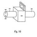
- FIG. 10is a diagram that illustrates various components of a surgical system 600.
- the surgical system 600may be configured as a hand-held device and may be employed in a manner that is different from an endoscope system.
- the surgical system 600may include a shaft 612 that is connected to a control module 614, which in turn is connected to a handle 650.
- the present inventionprovides advantages over conventional surgical, e.g., endoscope, systems.
- a conventional endoscopeis typically cleaned or disinfected prior to use within a patient in conformance with a standard referred to as high-level disinfectance, rather than sterilization. Sterilization provides a greater degree of cleanliness, and thus a high standard of patient safety, than high-level disinfectance.
- Conventional endoscopestypically can not be sterilized prior to use within a patient because the materials employed in the manufacture of conventional endoscopes are not sterilizable, and because conventional endoscope are typically not adequately sealed to withstand a sterilization process.
- various components of the endoscope system 10 of the present inventionmay be sterilizable or autoclavable, thereby providing a higher level of safety to a patient.
- various components of the endoscope system 10 of the present inventione.g., the shaft 12, the light source 26, the image capture device 28, the control module 14 and the power module 50, may be sterilizable or autoclavable, these components can be used more than once and on more than one patient, providing significant cost savings as compared to conventional endoscope systems that must be discarded after one use.
- the surgical systems of the present inventionemploy a light emitting diode or an array of light emitting diodes as the light source 26 at the distal end 12a of the shaft 12.
- the surgical systems of the present inventionmay provide for a more efficient use of the light as compared to conventional surgical, e.g., endoscope, systems employing a light source outside of the patient's body and a fiber-optic bundle to transport the light through the shaft, since these conventional surgical, e.g., endoscope, systems lose a large portion of the light before the light reaches the surgical site.
- a power sourcemay be provided at the distal end 12a of the shaft 12, or at any other location along the shaft 12, in the control module 14 or in the power module 50.
- the surgical system of the present inventionemploys a display screen 46 that is integral with the hand-held control module 14, thereby replacing the bulkiness and complexity of a separate television monitor for this purpose.
- the surgical system of the present inventionemploys power sources, motors, etc. that are integral with either the shaft 12, the control module 14 or the power module 50, enabling the surgical system to be self-contained, e.g., requiring no additional external power supplies, drive mechanisms, etc.
Landscapes
- Health & Medical Sciences (AREA)
- Life Sciences & Earth Sciences (AREA)
- Surgery (AREA)
- Engineering & Computer Science (AREA)
- Optics & Photonics (AREA)
- Physics & Mathematics (AREA)
- Heart & Thoracic Surgery (AREA)
- Animal Behavior & Ethology (AREA)
- Pathology (AREA)
- Radiology & Medical Imaging (AREA)
- Biophysics (AREA)
- Biomedical Technology (AREA)
- Veterinary Medicine (AREA)
- Medical Informatics (AREA)
- Molecular Biology (AREA)
- Nuclear Medicine, Radiotherapy & Molecular Imaging (AREA)
- General Health & Medical Sciences (AREA)
- Public Health (AREA)
- Signal Processing (AREA)
- Microelectronics & Electronic Packaging (AREA)
- Mechanical Engineering (AREA)
- Endoscopes (AREA)
- Surgical Instruments (AREA)
- Acyclic And Carbocyclic Compounds In Medicinal Compositions (AREA)
- External Artificial Organs (AREA)
Abstract
Description
- The present invention relates to a surgical system. More specifically, the present invention relates to a self-contained, sterilizable surgical system, such as an endoscope system.
- There are various different surgical systems that enable a surgical procedure or a surgical site to be viewed. One such type of surgical device is an endoscope. Such a device may be inserted into a patient's body during a surgical procedure to illuminate, view and/or manipulate a surgical site within the patient's body. Conventional endoscopes typically employ a flexible endoscope shaft, a first end of which is insertable into a patient's body. The shaft has a camera mounted at the first end and is connected at its second end to a power source for providing power to the camera. In addition, the shaft has a fiberoptic bundle that runs therethrough and connects to a light source outside of the patient's body. The light source is powered by another power source and the light from the light source is conveyed from the second end, through the fiber-optic bundle in the shaft, to the first end in order to illuminate a surgical site within the patient's body. In addition, the second end of the endoscope is connected to a television monitor, having still another power source, in order to display the images received by the camera.
- Thus, conventional surgical systems of this type, e.g., endoscope systems, are typically bulky, complex and difficult to maneuver.
- From
US-6 447 444 is known an endoscope with an image detector array (CCI) and a light source (LED) at its distal end. A disposable sheath covers the shaft of the endoscope. - The present invention relates to a surgical system, e.g., an endoscope system, as defined in claim 1. According to one embodiment, an endoscope system includes a shaft having a light source and/or an image capture device, e.g., a camera, each of which may be mounted at the distal end of the shaft or which may be connected to the distal end of the shaft by fiber optics. The light source may be a light emitting diode or an array of light emitting diodes, and may have its own power source located at the distal end of the shaft. The shaft has a sheath that is sealed so as to be sterilizable, e.g., autoclavable. The light source and/or the image capture device are also sealed within the distal end of the shaft so as to be sterilizable, e.g., autoclavable. The shaft also includes a working channel for permitting the passage of tools through the shaft, an inigation/aspiration channel for permitting fluid to be transmitted through the shaft, and an electric cable for transmitting data or power through the shaft.
- The shaft is coupled, either fixedly or detachably, at its proximal end to a control module having a video processor. Preferably, the control module is sterilizable, e.g., autoclavable. Image data received by the image capture device is transmitted via a data transfer cable of the electric cable in the shaft to the video processor and is displayed on an display screen integrally mounted to the control module. The control module may include an irrigation/aspiration system for conveying fluid through the irrigation/aspiration channel of the shaft. The control module may also include a control unit, which enables a user to control certain functions of the endoscope system, as well as a controller, which automatically controls certain functions of the endoscope system.
- The control module is coupled to a power module. The power module includes steering motors connected to steering cables in the shaft. In addition, the power module includes drive motors for driving, e.g., the irrigation/aspiration system, the steering motors, etc. The power module may also include a power source for providing power to the motors, the controller, the light source, the image capture device, etc. In one embodiment, the control module and the power module are contained in a single unit.
Figure 1 is a perspective view of several components of an endoscope system, according to one example embodiment of the present invention;Figure 2 is a perspective view of additional components of the endoscope system.illustrated inFigure 1 ;Figure 3 is a schematic view of a control unit of the endoscope system illustrated inFigure 1 ;Figure 4 is a front end view of a coupling of a power transfer cable illustrated inFigure 2 ;Figure 5 is a schematic view illustrating a motor arrangement of the endoscope system illustrated inFigures 2 ;Figure 6 is a schematic view of the endoscope system illustrated infigures 1 and2 ;Figure 7 is a schematic view of a memory device of the endoscope system illustrated inFigure 1 ;Figure 8 is a perspective view of several components of an endoscope system, according to another example embodiment of the present invention;Figure 9 is a perspective view of several components of an endoscope system, according to still another example embodiment of the present invention; andFigure 10 is a perspective view that illustrates several components of a hand-held surgical system, according to still another example embodiment of the present invention.- One example embodiment of a surgical system, in this case an
endoscope system 10, according to the present invention is illustrated inFigures 1 to 7 .Figure 1 illustrates several components of theendoscope system 10, including ashaft 12 and acontrol module 14 to which theshaft 12 is attached. Although the example embodiment described herein describes theshaft 12 as being fixedly attached to thecontrol module 14, it is recognized that, in alternative embodiments of the present invention, theshaft 12 may be detachably coupled to thecontrol module 14. Furthermore, it should be recognized that while thesurgical system 10 is described in connection with an endoscope, the surgical system may also be employed in connection with a proctoscope, an anoscope, etc. - According to one embodiment, the
shaft 12 includes atubular sheath 13, which may include a coating or other sealing arrangement to provide a fluid-tight seal between an interior region of theshaft 12 and the environment. Thesheath 13 is formed of a tissue-compatible, sterilizable elastomeric material. Preferably, thesheath 13 may be formed of a material that is autoclavable. In addition, thesheath 13 may be formed of a material having a high or relatively high lubricity. For instant, thesheath 13 may be formed of a material such as Teflon™ (i.e., a fluoropolymer, e.g., polytetrafluoroethylene - "PTFE"), silicone, a Teflon™/silicone combination, such as, for example, SIL-KORE™ (made by W.L Gore & Associates), "EPTFE", e.g., expanded teflon, etc. Other suitable materials and sealing arrangements that may be employed are described in further detail in Applicants' copendingU.S. Patent Application No. 10/099,634, filed on March 15,2002 - In this embodiment, the
shaft 12 has adistal end 12a, which is insertable into a patient's body, and aproximal end 12b, which is coupled, e.g., either fixedly or detachably, to thecontrol module 14. In this embodiment, both alight source 26 and animage capture device 28 are mounted on thedistal end 12a of theshaft 12. In other example embodiments, which do not form part of the invention, thelight source 26 and/or theimage capture device 28 are mounted in thecontrol module 14. If thelight source 26 is mounted in thecontrol module 14, the light may be transmitted from thelight source 26 to thedistal end 12a of theshaft 12 via fiber optics. If theimage capture device 28 is mounted in thecontrol module 14, the image data (including light reflected within a body, for example) may be transmitted to theimage capture device 28 from thedistal end 12a of theshaft 12 via fiber optics. - The
image capture device 28 may include a lens and an image sensor, e.g., a light sensitive device such as a CCD or CMOS-type image sensor, that is positioned to capture an image via the lens. In one embodiment, theimage capture arrangement 28 may further include a cleaning arrangement for cleaning debris from the lens. Thelight source 26 and theimage capture device 28 are sealed within thedistal end 12a of theshaft 12 such that thelight source 26 and theimage capture device 28 are also sterilizable, e.g., autoclavable. - According to the embodiment shown in
Figure 1 , theshaft 12 also defines anelectric cable 20 that extends from thedistal end 12a of theshaft 12 to theproximal end 12b of theshaft 12. According to one embodiment of the present invention, theelectric cable 20 includes apower transfer cable 22 and adata transfer cable 24. A distal end of thepower transfer cable 22 is coupled to thelight source 26 and/or to theimage capture device 28 that are mounted on thedistal end 12a of the shaft. A proximal end of thepower transfer cable 22 is coupled to a power source, such aspower source 44 disposed in thecontrol module 14 or, alternatively, to apower source 62 disposed in the power module 50 (described in greater detail below in connection withFigure 2 ). Thepower transfer cable 22 may be configured to provide power from thepower source 44 or thepower source 62 to thelight source 26 and/or theimage capture device 28. - Alternatively or additionally, an additional power source may be mounted at the
distal end 12a of theshaft 12 adjacent to thelight source 26 and theimage capture device 28, and may provide power to thelight source 26 and/or theimage capture device 28. For instance,Figure 8 illustrates one embodiment of the present invention, in which anendoscope system 400 has anadditional power source 27a that is mounted at thedistal end 12a of theshaft 12 adjacent to thelight source 26 and theimage capture device 28. Theadditional power source 27a provides power to thelight source 26 and/or theimage capture device 28. Thus, according to this embodiment, the need for thepower transfer cable 22 in theshaft 12 may be eliminated, thereby decreasing the cross-sectional area of theshaft 12 if desired. Since theshaft 12 may during operation be inserted through an incision made by a surgeon in a patient, and since it is generally desirable to minimize the size of such incisions, e.g., for healing purposes, a decrease in the cross-sectional area of theshaft 12 may be advantageous in that it requires a smaller incision for insertion into a patient. - It should be understood that, according to various other embodiments of the present invention, the power source for the
light source 26 and theimage capture device 28 may be located at any position along theshaft 12, or may be located at any other position. In those embodiments in which the power source for thelight source 26 and theimage capture device 28 are located at a position along theshaft 12, thepower transfer cable 22 may extend within theshaft 12 between thelight source 26 and/or theimage capture device 28 and the power source. For instance,Figure 9 illustrates another embodiment of the present invention, in which anendoscope system 500 has anadditional power source 27b that is located within a portion of theshaft 12, between thedistal end 12a and theproximal end 12b of theshaft 12. Theadditional power source 27b provides power to either or both of thelight source 26 and theimage capture device 28. Thus, according to this embodiment, the need for thepower transfer cable 22 in theshaft 12 may be partially eliminated, e.g., in the portion of the shaft between theadditional power source 27b and theproximal end 12b of theshaft 12. - Referring back to
Figure 1 , thelight source 26 mounted to thedistal end 12a of theshaft 12 may be any type of light source, but may include a light emitting diode or an array of light emitting diodes. The light emitting diode or array of light emitting diodes may emit, e.g., white light The relatively low power requirements for a light emitting diode, or for an array of light emitting diodes, as compared to the power requirements for the light source of a conventional endoscope system, enables the power source to be positioned at thedistal end 12a of theshaft 12. - As mentioned above, the
electric cable 20 in theshaft 12 may also include adata transfer cable 24. A distal end of thedata transfer cable 24 is coupled to theimage capture device 28 that is mounted on thedistal end 12a of theshaft 12. A proximal end of thedata transfer cable 24 is coupled to avideo processing module 30 disposed within thecontrol module 14. In this embodiment, thevideo processor 30 is configured to receive data signals from theimage capture device 28 via thedata transfer cable 24. Alternatively, theshaft 12 may not have adata transfer cable 24 but rather a wireless receive and transmitter arrangement that enables the data to be transferred wirelessly. - According to one embodiment of the present invention, the
shaft 12 may also include a workingchannel 16 that extends from thedistal end 12a of theshaft 12 to theproximal end 12b of theshaft 12. At thedistal end 12a of theshaft 12 is a workingchannel orifice 16a that leads into the workingchannel 16. The workingchannel 16 communicates with a workingchannel passage 16c disposed in thecontrol module 14, so that the workingchannel 16 is accessible to a user via the workingchannel passage 16c in thecontrol module 14. The workingchannel 16 may be configured to permit the passage of small endoscopic tools or the like, such as a cutting blade, thereby enabling a user to manipulate tissue positioned adjacent to thedistal end 12a of theshaft 12 through theshaft 12 and without removing thedistal end 12a of theshaft 12 from the patient's body. - According to one embodiment of the present invention, the
shaft 12 also includes an irrigation/aspiration channel 32 that extends from thedistal end 12a of theshaft 12 to theproximal end 12b of theshaft 12. At thedistal end 12a of theshaft 12 is an irrigation/aspiration channel orifice 32a that leads into the irrigation/aspiration channel 32. The irrigation/aspiration channel 32 may be coupled to or in communication with an irrigation/aspiration system 19 disposed in thecontrol module 14 and/or the power module 50 (described below in connection withFigure 2 ). The irrigation/aspiration channel 32 is configured to convey fluid in a first direction through the irrigation/aspiration channel 32, e.g., towards thedistal end 12a of theshaft 12, in order to irrigate a surgical site, and/or to convey fluid in the opposite direction through the irrigation/aspiration channel 32, e.g., away from thedistal end 12a of theshaft 12, in order to aspirate a surgical site. - According to one embodiment of the present invention, the
shaft 12 also defines at least one steering cable for steering at least a portion of theshaft 12. In one embodiment, the entire length of theshaft 12 is steerable, while according to other embodiments, only a portion of theshaft 12, such as a portion adjacent to thedistal end 12a of theshaft 12, is steerable. In the example embodiment shown, theshaft 12 includes afirst steering cable 34 and asecond steering cable 36. Thefirst steering cable 34 is configured to steer theshaft 12 in first and second directions that are 180 degrees apart relative to each other, e.g., north-south, while thesecond steering cable 36 is configured to steer theshaft 12 in third and fourth directions that are 180 degrees apart relative to each other and that are 90 degrees apart relative to the first and second directions, e.g., east-west. It should be understood that reference herein to north, south, east and west is made to a relative coordinate system. Advantageously, each of thefirst steering cable 34 and thesecond steering cable 36 extends from thedistal end 12a of theshaft 12, or from a location near to thedistal end 12a of theshaft 12, to theproximal end 12b of theshaft 12. It should be understood, however, that while a single steering cable is shown and described herein for steering theshaft 12 in each of the above-mentioned directions, other embodiments of the present invention may employ more than one steering cable for these purposes, as is described below. The steering cables may be arranged and configured as described, for example, inU.S. Patent Application Serial No. 09/510,923 , entitled "A Carriage Assembly for Controlling a Steering Wire Mechanism Within a Flexible Shaft, " (WO-01/62 163 - At the
proximal end 12b of theshaft 12, thefirst steering cable 34 and thesecond steering cable 36 are coupled to drive elements of thecontrol module 14 and/or thepower module 50. One such arrangement, which is shown and described inFigure 3 (discussed in greater detail below), provides that thefirst steering cable 34 and thesecond steering cable 36 are coupled to driveshafts steering motors - As mentioned above,
Figure 1 also illustrates acontrol module 14 for controlling the operation of theendoscope system 10. Advantageously, thecontrol module 14 is a hand-held device that provides acontrol unit 150 having control mechanisms for a user to control certain functions of theendoscope system 10. Preferably, thecontrol module 14, either separately or when connected to theshaft 12, is sterilizable, e.g., autoclavable. Thecontrol module 14 includes acontroller 122 coupled to the various components of theshaft 12, thecontrol module 14 and thepower module 50. Advantageously, thecontroller 122 is configured to control additional functions of theendoscope system 10.Figure 6 , which is described in greater detail below, illustrates schematically one embodiment of thecontroller 122 connected to other components of theendoscope system 10. - According to the example embodiment of the present invention, the
control module 14 includes avideo processor 30 that receives data signals from theimage capture device 28 via thedata transfer cable 24 of theshaft 12 or via the wireless arrangement. Thecontrol module 14 may also include anintegral display screen 46 that is coupled to thevideo processor 30. Upon receiving signals from theimage capture device 28 via thedata transfer cable 24, thevideo processor 30 is configured to process the signals and to display an image on thedisplay screen 46 corresponding to the image received by theimage capture device 28. According to one embodiment, thedisplay screen 46 is moveable, e.g., rotatable, slidable, etc., relative to thecontrol module 14. In this manner, thedisplay screen 46 may be hidden from view when in the retracted position and may be viewable by a user when in an extended position. As previously mentioned, thecontrol module 14 may be configured with appropriate materials and seals such that, when thedisplay screen 46 in the retracted position, thecontrol module 14 is sterilizable, e.g., autoclavable. Thus, thecontrol module 14 including thedisplay screen 46 may be protected from any environment which they may be employed in. - In addition to the video data received from the image capture device, the
display screen 46 may display data corresponding to the operation of theendoscopic system 10. For instance, according to one embodiment, thedisplay screen 46 provides an indication, via indicators such asindicators Figure 6 and described in greater detail below), corresponding to whether the system is turned on or off, or corresponding to the status of the steering cables, the irrigation/aspiration system 19, or any other aspect of theendoscopic system 10. - The
control module 14 may also include an irrigation/aspiration system 19, such as a pump, that is configured to pump fluid in a first direction through the irrigation/aspiration channel 32 toward thedistal end 12a of theshaft 12 in order to irrigate a surgical site. In addition, thecontrol module 14 may include a second, or the same, pump (not shown) that is configured to pump fluid in the opposite direction through the irrigation/aspiration channel 32 away from thedistal end 12a of theshaft 12 so as to aspirate the surgical site. The operation of the irrigation/aspiration system may be controlled by an irrigation/aspiration control switch 39 of acontrol unit 150 of thecontrol module 14. The pump may be powered by thepower source 44 in thecontrol module 14, by thepower source 62 in thepower module 50, or by any other power source. - The
control module 14 is coupled to oneend 48a of apower transfer cable 48. Thepower transfer cable 48 may be fixedly or detachably coupled to thecontrol module 14. Additional features of thepower transfer cable 48 are described in connection withFigure 2 below. - The
control module 14 may also include, as part of thecontrol unit 150, asteering controller 1300, aswitch 312 and a two-way rocker 314. Thesteering controller 1300, theswitch 312 and the two-way rocker 314 are described in more detail below in connection withFigure 3 . Figure 2 illustrates apower module 50 to which thecontrol module 14 may be fixedly or detachably coupled. Although the example embodiment described herein includes thepower module 50 being detachably coupled to thecontrol module 14, it should be appreciated that, in alternative embodiments of the present invention, thepower module 50 may be fixedly coupled to thecontrol module 14. In this embodiment, thepower module 50 may be worn by a user, such as by usingbelt 51.- The
control module 14 is coupled to thepower module 50 via apower transfer cable 48. As illustrated inFigure 2 , thepower transfer cable 48 may be detachably coupled by acoupling 56 at anend 48b of thepower transfer cable 48 to a correspondingcoupling 58 of the power module SO. According to one embodiment, thecoupling 56 may include akey structure 56a to properly orient thecoupling 56 to the mating andcomplementary coupling 58 disposed on thepower module 50. Suchkey structure 56a may be provided on either one, or both, of thecoupling 56 and the mating andcomplementary coupling 58 disposed on thepower module 50. For instance, thecoupling 56 may include a quick-connect type connectors, which may use, for example, a simple pushing motion to engage thecoupling 56 of thepower transfer cable 48 to thecoupling 58 of thepower module 50. Seals may be provided in order to provide a fluid-tight seal between the interior of thecoupling 56 and the environment In an alternative embodiment, thepower transfer cable 48 is fixedly coupled both at itsfirst end 48a to the control module 14 (seeFigure 1 ), and at itssecond end 48b to thepower module 50. - Advantageously, the
power module 50 also houses steering and drive motors. For instance, according to one embodiment of the present invention, thepower module 50 houses several steering motors for operating thesteering cables shaft 12. One example embodiment of such an arrangement of steering motors is illustrated inFigure 5 , which is described in greater detail below. In addition, according to one embodiment of the present invention, thepower module 50 houses a drive motor for operating the irrigation/aspiration system 19, etc. - In addition, the
power module 50 may include afluid reservoir 60 and apower source 62, such as a battery. According to one embodiment, thefluid reservoir 60 and thepower source 62 are removable from thepower module 50. In this manner, thefluid reservoir 60 may be refilled with fluid, e.g., water, as needed. According to one embodiment of the present invention, thefluid reservoir 60 may provide fluid to be pumped to a surgical site by an irrigation/aspiration system 19. Alternatively, thefluid reservoir 60 may store fluid removed from a surgical site by the irrigation/aspiration system 19. In this embodiment, thefluid reservoir 60 may be removed from thepower module 50 in order to be emptied of its contents. In addition, thepower source 62 may be removable from thepower module 50 in order to be recharged as needed. As previously mentioned, thepower source 62 may provide power, according to various embodiments of the present invention, to thelight source 26 and theimage capture device 28. In this embodiment, however, thepower source 62 provides power to thecontroller 122 and/or the irrigation/aspiration system 19 and/or the steering and drive motors, etc. disposed in thecontrol module 14 and thepower module 50. According to still another embodiment, thepower module 50 includes apower cord 59 that enables thepower module 50 to be plugged into an electrical socket (not shown) or other conventional power source, thereby eliminating the need for thepower source 62 or providing back-up power for thepower source 62. - Referring now to
Figure 6 , there is seen a schematic view of theendoscopic system 10. Thecontroller 122 may be disposed in thecontrol module 14, and is configured to control various functions and operations of theendoscopic system 10. Amemory unit 130 is provided and may include memory devices, such as, a ROM component 132 and/or aRAM component 134 for storing programs or algorithms employed by thecontroller 122. ROM component 132 is in electrical and logical communication withcontroller 122 via line 136, andRAM component 134 is in electrical and logical communication withcontroller 122 vialine 138.RAM component 134 may include any type of random-access memory, such as, for example, a magnetic memory device, an optical memory device, a magneto-optical memory device, an electronic memory device, etc. Similarly, ROM component 132 may include any type of read-only memory, such as, for example, a removable memory device, such as a PC-Card or PCMCIA-type device. It should be appreciated that ROM component 132 andRAM component 134 may be embodied as a single unit or may be separate units and that ROM component 132 and/orRAM component 134 may be provided in the form of a PC-Card or PCMCIA-type device. - The
controller 122 is further connected to thedisplay screen 46 via line 154 and to theindicators respective lines 156, 158.Lines 124, 126, 128 electrically and logically connectcontroller 122 tomotors control unit 150, which may include the control features of thecontrol module 14 such as asteering controller 1300. the irrigation/aspiration system switch 39, etc. is electrically and logically connected tocontroller 122 vialine 152. Additional features of thecontrol unit 150 are illustrated inFigure 3 , which is described in greater detail below. In addition, thecontroller 122 may be electrically and logically connected bydata transfer cable 24 to theimage capture device 28. Furthermore, thecontroller 122 may be electrically and logically connected byline 120 to one ormore memory units 174, an example of which is illustrated inFigure 7 and described in greater detail below. - As described above, the
power module 50 includes motors configured to drive thesteering cables Figure 5 illustrates schematically one possible arrangement of motors within thepower module 50. In the example embodiment illustrated schematically inFigure 5 , threeelectric motors power source 62, are disposed in thepower module 50. It should be appreciated, however, that any appropriate number of motors may be provided for this purpose, and the motors may operate via battery power, line current a DC power supply, an electronically controlled DC power supply, AC power, etc, It should also be appreciated that thesteering motors - According to one embodiment of the present invention, at the
proximal end 12b of theshaft 12, thefirst steering cable 34 and thesecond steering cable 36 are coupled to drive elements (not shown) of thecontrol module 14 that in turn are coupled to driveshafts steering motors power module 50. It should be appreciated that, according to various other embodiments of the present invention, driveshafts steering motors control module 14. - Referring to
Figure 5 , anoutput shaft 86 of amotor 84 engages aconnector 63 of thecoupling 56 of thepower transfer cable 48 when thecoupling 56 is engaged with thepower module 50 to thereby drive thefirst steering cable 34. It should be understood that, while only asingle steering cable 34 is shown and described for steering theshaft 12 in the north-south direction, the present invention may employ, in accordance with an alternative embodiment of the invention, a pair of steering cables via a pulley arrangement for this purpose. In addition, anoutput shaft 92 of amotor 90 engages theconnector 66 of thecoupling 56 when thecoupling 56 is engaged with thepower module 50 to thereby drive thesecond steering cable 36. Again, it should be understood that, while only asingle steering cable 36 is shown and described for steering theshaft 12 in the east-west direction, the present invention may employ, in accordance with an alternative embodiment of the invention, a pair of steering cables via a pulley arrangement for this purpose. Themotors carriage 100, which is selectively movable via anoutput shaft 98 of amotor 96 between a first position and a second position to selectively engage and disengage themotors shaft 12 to become taut and steerable or limp as necessary. It should be appreciated that other mechanical, electrical or electro-mechanical mechanisms may be used to selectively engage and disengage the steering mechanism. The motors may be arranged and configured as described, for example, inU.S. Patent Application Serial No. 09/510,923 , entitled "A Carriage Assembly for Controlling a Steering Wire Mechanism Within a Flexible Shaft,". - Referring now to
Figure 4 , there is illustrated a front end view of thecoupling 56 of thepower transfer cable 48. Thecoupling 56 includes afirst connector 63 and asecond connector 66, each rotatably secured to thecoupling 56. Each of theconnectors respective recess 63a, 66a Each of therecesses 63a, 66a may be hexagonally shaped. It should be appreciated, however, that therecesses 63a, 66a may have any shape and configuration to non-rotatably couple and rigidly attach theconnectors respective drive shafts power module 50, as more fully described below. It should be appreciated that complementary projections may be provided onrespective drive shafts steering cables shaft 12 as described below. It should also be appreciated that the recesses may be provided on thedrive shafts connectors connectors drive shafts connectors steering cables distal end 12a of theshaft 12.Figure 4 also illustrates afluid connector 73. Thefluid connector 73 provides a connection from thefluid reservoir 60 in thepower module 50 to the irrigation/aspiration system 19 in thecontrol module 14. In addition,Figure 4 illustrates apower connector 75. In the above-described embodiments wherein thepower source 62 provides power to components of theshaft 12 and thecontrol module 14, thepower connection 75 provides a connection from thepower source 62 to these components. - Referring now to
Figure 3 , there is seen a schematic view of thecontrol unit 150 of thecontrol module 14. In accordance with one embodiment of the present invention, thecontrol unit 150 includes asteering controller 1300, having a plurality ofswitches way rocker 1310. The operation of theswitches rocker 1310, controls the operation of thefirst steering cable 34 via thesteering motor 84. Similarly, the operation of theswitches rocker 1310, controls the operation of thesecond steering cable 36 via thesteering motor 90. It should be appreciated that therocker 1310 and theswitches switches shaft 12 in the north-south direction and that the operation of theswitches shaft 12 in the east-west direction. Again, reference herein to north, south, east and west is made to a relative coordinate system. Alternatively, a digital joystick analog joystick, etc. may be provided in place of therocker 1310 and theswitches switches - Furthermore, the
control unit 150 may include aswitch 312, which further controls certain functions of theendoscope system 10 in accordance with an operating program or algorithm employed by thecontroller 122. For instance, the operation ofswitch 312 may control the operation of themotor 96 to selectively engage and disengage the steering mechanism, or may control the activation of thelight source 26 or theimage capture device 28. Thecontrol unit 150 may also be provided with aswitch 39, the operation of which may further control other functions of theendoscope system 10 in accordance with the operating program or algorithm employed by thecontroller 122. For example, operation of theswitch 39 may control the activation of the irrigation/aspiration system 19. Thecontrol unit 150 may also include a two-way rocker 314 having first andsecond switches 316, 318 operable thereby. The operation of theseswitches 316, 318 may control still other functions of theendoscope system 10 in accordance with the operating program or algorithm employed by thecontroller 122. For example, operation of the two-way rocker 314 may control a zoom or magnification function of theimage capture device 28. - The
control unit 150 may include a separate controller 322, which is electrically and logically connected with the switches 302, 304, 306, 308 vialine 324, with theswitches 316, 318 vialine 326, withswitch 312 vialine 328 and withswitch 39 vialine 330. Theindicators display device 46 may be electrically and logically connected to the controller 322 rather thancontroller 122. - According to one embodiment of the present invention, one or more of the
shaft 12, thecontrol module 14 and thepower module 50 may include a memory unit, such asmemory unit 174 illustrated schematically inFigure 7 . Thememory unit 174 may store information as described, for example, inU.S. Patent Application Serial No. 09/723,715, filed on November 28, 2000 U.S. Patent Application Serial No. 09/836,781, filed on April 17, 2001 U.S. Patent Application Serial No. 09/887,789, filed on June 22, 2001 U.S. Patent Application Serial No. 10/099,634, filed on March 15, 2002 Figure 7 , thememory unit 174 may include adata connector 272 that includescontacts 276, each electrically and logically connected tomemory unit 174 via arespective line 278.Memory unit 174 is configured to store, for example, aserial number data 180, an attachment type identifier (ID)data 182 and ausage data 184.Memory unit 174 may additionally store other data. Both theserial number data 180 and theID data 182 may be configured as read-only data. In the example embodiment,serial number data 180 is data uniquely identifying the particular component, whereas theID data 182 is data identifying the type of the component, such as, for example, a shaft. Theusage data 184 represents usage of the particular component, such as, for example, the number of times theshaft 12 has been employed or the number of times that thelight source 26 has been activated, It should be appreciated that theshaft 12 may be designed and configured to be used a single time or, in such embodiments wherein theshaft 12 is sterilizable or autoclavable, multiple times. Thecontrol module 14 and/or thepower module 50 may also be designed and configured to be used a predetermined number of times. Accordingly, theusage data 184 may be used to determine whether theshaft 12 has been used and/or whether the number of uses has exceeded the maximum number of permitted uses. According to one embodiment, an attempt to use the shaft 12 (or thecontrol module 14 and the power module 50) after the maximum number of permitted uses has been reached may generate an ERROR condition. - While the present invention has been described hereinabove in connection with endoscope systems, it should be recognized that other types of surgical systems may be employed for various different types of surgical procedures, e.g., proctoscopy, anoscopy, etc. For instance,
Figure 10 is a diagram that illustrates various components of a surgical system 600. The surgical system 600 may be configured as a hand-held device and may be employed in a manner that is different from an endoscope system. The surgical system 600 may include ashaft 612 that is connected to acontrol module 614, which in turn is connected to ahandle 650. For the purposes of clarity, other features of the surgical systems that are illustrated inFigures 1 to 9 , e.g., the control module, display screen, power sources, etc., are not illustrated inFigure 10 . However, it should be recognized that, in accordance with various embodiments of the present invention, any or all of these features may be employed in the surgical system 600. - The present invention, in accordance with various embodiments thereof, provides advantages over conventional surgical, e.g., endoscope, systems. For instance, a conventional endoscope is typically cleaned or disinfected prior to use within a patient in conformance with a standard referred to as high-level disinfectance, rather than sterilization. Sterilization provides a greater degree of cleanliness, and thus a high standard of patient safety, than high-level disinfectance. Conventional endoscopes typically can not be sterilized prior to use within a patient because the materials employed in the manufacture of conventional endoscopes are not sterilizable, and because conventional endoscope are typically not adequately sealed to withstand a sterilization process. Unlike conventional endoscope systems, various components of the
endoscope system 10 of the present invention, most particularly theshaft 12, thelight source 26, theimage capture device 28, thecontrol module 14 and in some instances thepower module 50, may be sterilizable or autoclavable, thereby providing a higher level of safety to a patient. Furthermore, because various components of theendoscope system 10 of the present invention, e.g., theshaft 12, thelight source 26, theimage capture device 28, thecontrol module 14 and thepower module 50, may be sterilizable or autoclavable, these components can be used more than once and on more than one patient, providing significant cost savings as compared to conventional endoscope systems that must be discarded after one use. - In addition, according to some embodiments, the surgical systems of the present invention employ a light emitting diode or an array of light emitting diodes as the
light source 26 at thedistal end 12a of theshaft 12. Thus, the surgical systems of the present invention may provide for a more efficient use of the light as compared to conventional surgical, e.g., endoscope, systems employing a light source outside of the patient's body and a fiber-optic bundle to transport the light through the shaft, since these conventional surgical, e.g., endoscope, systems lose a large portion of the light before the light reaches the surgical site. In addition, the use by the present invention of a light emitting diode or an array of light emitting diodes provides satisfactory illumination of a surgical site while requiring very little power. Thus, according to one embodiment, a power source may be provided at thedistal end 12a of theshaft 12, or at any other location along theshaft 12, in thecontrol module 14 or in thepower module 50. - In addition, according to some embodiments, the surgical system of the present invention employs a
display screen 46 that is integral with the hand-heldcontrol module 14, thereby replacing the bulkiness and complexity of a separate television monitor for this purpose. Furthermore, according to some embodiments, the surgical system of the present invention employs power sources, motors, etc. that are integral with either theshaft 12, thecontrol module 14 or thepower module 50, enabling the surgical system to be self-contained, e.g., requiring no additional external power supplies, drive mechanisms, etc. - Thus, the several aforementioned objects and advantages of the present invention are most effectively attained. Those skilled in the art will appreciate that numerous modifications of the exemplary embodiment described hereinabove may be made without departing from the scope of the invention. Although a single exemplary embodiment of the present invention has been described and disclosed in detail herein, it should be understood that this invention is in no sense limited thereby.
Claims (15)
- A surgical device (10) selected from an endoscope, a proctoscope or an anoscope comprising:a flexible shaft (12) having a distal end (12a) and a proximal end (12b), the shaft (12) having:a tubular sheath (13) formed of a tissue-compatible, sterilizable elastomeric material, the tubular sheath (13) extending from, the distal end (12a) to the proximal end (12b) and being sealed to provide a fluid tight seal such that the shaft is sterilizable for multiple use;an image capture device (28) configured to receive image data from the distal end (12a) of the shaft (12); anda light source (26) at the distal end (12a) of the shaft (12); andwherein the light source (26) is a light-emitting diode or an array of light-emitting diodes, and the image capture device (28) and the light source (26) are sealed within the distal end of the shaft so as to be sterilizable for multiple use.
- The surgical device of claim 1, wherein the light source is an array of light-emitting diodes.
- The surgical device (10) of claim 1 or claim 2, wherein the image capture device (28) is one of a camera and a CCD.
- The surgical device (10) of any preceding claims, further comprising a power source (44) for providing power to the light source (26), the power source (26) located at the distal end (12a) of the shaft (12).
- The surgical device (10) of any preceding claim, further comprising a control module (14), preferably detachably, coupled to the proximal end (12b) of the shaft (12).
- The surgical device (10) of claim 5, wherein the control module (14) is sterilisable.
- The surgical device (10) of claim 6, wherein the control module (14) is autoclavable.
- The surgical device (10) of any of claims 5 to 7, wherein the control module (14) includes a video processor (30).
- The surgical device (10) of any preceding claim, wherein the shaft (12) includes a data transfer cable (24), and wherein the image data received by the image capture device (28) is transmitted via the data transfer cable (24) to the video processor (30).
- The surgical device (10) of any of claims 1 to 8, further comprising a wireless arrangement configured to transfer image data received by the image capture device (28) to the video processor (30).
- The surgical device (10) of any preceding claim, further comprising a display screen (46), which is preferably integrally mounted to the controls module (14).
- The surgical device (10) of any of claims 5 to 11, wherein the shaft (12) includes at least one of:an irrigation/aspiration channel (32), and wherein the control module (14) includes an irrigation/aspiration system (19) for conveying fluid through the irrigation/aspiration channel (32) of the shaft (12); anda working channel (16) for permitting the passage of tools through the shaft (12).
- The surgical device (10) of any of claims 5-12, further comprising a power module (50) coupled to the control module (14), the power module (50) being configured to provide power to components housed in at least one of the control module (14) and the shaft (12), wherein if the power module (50) is configured to provide power to components housed in the shaft (12), the shaft (12) preferably includes a power transfer cable (22).
- The surgical device (10) of claim 13, wherein the power module (50) includes a pump connected to the irrigation/aspiration system (19) for at least one of introducing or removing fluid via the irrigation/aspiration channel (32).
- The surgical device (10) according to any of the preceding claims configured as a hand held device.
Priority Applications (1)
| Application Number | Priority Date | Filing Date | Title |
|---|---|---|---|
| EP10010190.6AEP2277434B1 (en) | 2002-09-30 | 2003-09-30 | Self-contained sterilizable surgical system |
Applications Claiming Priority (2)
| Application Number | Priority Date | Filing Date | Title |
|---|---|---|---|
| US41531302P | 2002-09-30 | 2002-09-30 | |
| EP03759612AEP1545289B1 (en) | 2002-09-30 | 2003-09-30 | Self-contained sterilizable surgical system |
Related Parent Applications (1)
| Application Number | Title | Priority Date | Filing Date |
|---|---|---|---|
| EP03759612.9Division | 2003-09-30 |
Related Child Applications (1)
| Application Number | Title | Priority Date | Filing Date |
|---|---|---|---|
| EP10010190.6Division-Into | 2010-09-22 |
Publications (2)
| Publication Number | Publication Date |
|---|---|
| EP2186465A1 EP2186465A1 (en) | 2010-05-19 |
| EP2186465B1true EP2186465B1 (en) | 2012-04-25 |
Family
ID=32069839
Family Applications (3)
| Application Number | Title | Priority Date | Filing Date |
|---|---|---|---|
| EP03759612AExpired - LifetimeEP1545289B1 (en) | 2002-09-30 | 2003-09-30 | Self-contained sterilizable surgical system |
| EP09014665AExpired - LifetimeEP2186465B1 (en) | 2002-09-30 | 2003-09-30 | Self-contained sterilizable surgical system |
| EP10010190.6AExpired - LifetimeEP2277434B1 (en) | 2002-09-30 | 2003-09-30 | Self-contained sterilizable surgical system |
Family Applications Before (1)
| Application Number | Title | Priority Date | Filing Date |
|---|---|---|---|
| EP03759612AExpired - LifetimeEP1545289B1 (en) | 2002-09-30 | 2003-09-30 | Self-contained sterilizable surgical system |
Family Applications After (1)
| Application Number | Title | Priority Date | Filing Date |
|---|---|---|---|
| EP10010190.6AExpired - LifetimeEP2277434B1 (en) | 2002-09-30 | 2003-09-30 | Self-contained sterilizable surgical system |
Country Status (10)
| Country | Link |
|---|---|
| US (2) | US8696552B2 (en) |
| EP (3) | EP1545289B1 (en) |
| JP (3) | JP4746320B2 (en) |
| CN (2) | CN1684626A (en) |
| AT (2) | ATE554695T1 (en) |
| AU (1) | AU2003275336A1 (en) |
| CA (1) | CA2500243C (en) |
| DE (1) | DE60332362D1 (en) |
| ES (2) | ES2382762T3 (en) |
| WO (1) | WO2004030526A1 (en) |
Families Citing this family (245)
| Publication number | Priority date | Publication date | Assignee | Title |
|---|---|---|---|---|
| US8241322B2 (en)* | 2005-07-27 | 2012-08-14 | Tyco Healthcare Group Lp | Surgical device |
| US10285694B2 (en) | 2001-10-20 | 2019-05-14 | Covidien Lp | Surgical stapler with timer and feedback display |
| US7464847B2 (en) | 2005-06-03 | 2008-12-16 | Tyco Healthcare Group Lp | Surgical stapler with timer and feedback display |
| JP4564239B2 (en)* | 2003-04-11 | 2010-10-20 | オリンパス株式会社 | Endoscope device |
| DE10346598A1 (en)* | 2003-10-07 | 2005-05-04 | Henke Sass Wolf Gmbh | Electronic endoscope |
| US9055943B2 (en) | 2007-09-21 | 2015-06-16 | Covidien Lp | Hand held surgical handle assembly, surgical adapters for use between surgical handle assembly and surgical end effectors, and methods of use |
| US11311291B2 (en) | 2003-10-17 | 2022-04-26 | Covidien Lp | Surgical adapter assemblies for use between surgical handle assembly and surgical end effectors |
| US8968276B2 (en) | 2007-09-21 | 2015-03-03 | Covidien Lp | Hand held surgical handle assembly, surgical adapters for use between surgical handle assembly and surgical end effectors, and methods of use |
| US10041822B2 (en) | 2007-10-05 | 2018-08-07 | Covidien Lp | Methods to shorten calibration times for powered devices |
| US10022123B2 (en) | 2012-07-09 | 2018-07-17 | Covidien Lp | Surgical adapter assemblies for use between surgical handle assembly and surgical end effectors |
| US10105140B2 (en) | 2009-11-20 | 2018-10-23 | Covidien Lp | Surgical console and hand-held surgical device |
| US8517921B2 (en)* | 2004-04-16 | 2013-08-27 | Gyrus Acmi, Inc. | Endoscopic instrument having reduced diameter flexible shaft |
| US7947034B2 (en) | 2004-07-30 | 2011-05-24 | Tyco Healthcare Group Lp | Flexible shaft extender and method of using same |
| JP2008514363A (en)* | 2004-09-30 | 2008-05-08 | ボストン サイエンティフィック リミテッド | Multifunctional endoscope system for use in electrosurgical applications |
| US11291443B2 (en) | 2005-06-03 | 2022-04-05 | Covidien Lp | Surgical stapler with timer and feedback display |
| CN101495046B (en) | 2005-07-27 | 2012-12-12 | Tyco医疗健康集团 | e.g. shafts for electromechanical surgical equipment |
| US20070049794A1 (en)* | 2005-09-01 | 2007-03-01 | Ezc Medical Llc | Visualization stylet for medical device applications having self-contained power source |
| EP2486862B1 (en)* | 2006-05-19 | 2019-03-27 | Ethicon Endo-Surgery, Inc. | Electrical surgical instrument |
| TWM309970U (en)* | 2006-09-13 | 2007-04-21 | Tien-Sheng Chen | Laryngoscope with wireless image transmission |
| US7976459B2 (en)* | 2006-10-17 | 2011-07-12 | Intra L.L.C. | Portable endoscope for intubation |
| US20080188714A1 (en)* | 2007-02-07 | 2008-08-07 | Boston Scientific Scimed, Inc. | Electromechanical in-situ cleaning of optical elements |
| DE102008018931A1 (en) | 2007-04-17 | 2008-11-13 | Gyrus ACMI, Inc., Southborough | Light source power based on a predetermined detected condition |
| US8028882B2 (en)* | 2007-05-01 | 2011-10-04 | Tyco Healthcare Group | Anvil position detector for a surgical stapler |
| US9023014B2 (en) | 2007-09-21 | 2015-05-05 | Covidien Lp | Quick connect assembly for use between surgical handle assembly and surgical accessories |
| AU2008302043B2 (en) | 2007-09-21 | 2013-06-27 | Covidien Lp | Surgical device |
| US10498269B2 (en) | 2007-10-05 | 2019-12-03 | Covidien Lp | Powered surgical stapling device |
| US8517241B2 (en) | 2010-04-16 | 2013-08-27 | Covidien Lp | Hand-held surgical devices |
| US10779818B2 (en) | 2007-10-05 | 2020-09-22 | Covidien Lp | Powered surgical stapling device |
| US8366603B2 (en) | 2007-12-21 | 2013-02-05 | Boston Scientific Scimed, Inc. | Endoscope including a multifunction conductor |
| US20090209826A1 (en)* | 2008-01-09 | 2009-08-20 | Ezc Medical Llc | Intubation systems and methods |
| US9402533B2 (en) | 2011-03-07 | 2016-08-02 | Endochoice Innovation Center Ltd. | Endoscope circuit board assembly |
| US11864734B2 (en) | 2009-06-18 | 2024-01-09 | Endochoice, Inc. | Multi-camera endoscope |
| US10165929B2 (en) | 2009-06-18 | 2019-01-01 | Endochoice, Inc. | Compact multi-viewing element endoscope system |
| US9101287B2 (en) | 2011-03-07 | 2015-08-11 | Endochoice Innovation Center Ltd. | Multi camera endoscope assembly having multiple working channels |
| US11547275B2 (en) | 2009-06-18 | 2023-01-10 | Endochoice, Inc. | Compact multi-viewing element endoscope system |
| US12137873B2 (en) | 2009-06-18 | 2024-11-12 | Endochoice, Inc. | Compact multi-viewing element endoscope system |
| US9101268B2 (en) | 2009-06-18 | 2015-08-11 | Endochoice Innovation Center Ltd. | Multi-camera endoscope |
| US8926502B2 (en) | 2011-03-07 | 2015-01-06 | Endochoice, Inc. | Multi camera endoscope having a side service channel |
| US9706903B2 (en) | 2009-06-18 | 2017-07-18 | Endochoice, Inc. | Multiple viewing elements endoscope system with modular imaging units |
| US9492063B2 (en) | 2009-06-18 | 2016-11-15 | Endochoice Innovation Center Ltd. | Multi-viewing element endoscope |
| US11278190B2 (en) | 2009-06-18 | 2022-03-22 | Endochoice, Inc. | Multi-viewing element endoscope |
| US9642513B2 (en) | 2009-06-18 | 2017-05-09 | Endochoice Inc. | Compact multi-viewing element endoscope system |
| US9901244B2 (en) | 2009-06-18 | 2018-02-27 | Endochoice, Inc. | Circuit board assembly of a multiple viewing elements endoscope |
| WO2010146587A1 (en) | 2009-06-18 | 2010-12-23 | Peer Medical Ltd. | Multi-camera endoscope |
| US9872609B2 (en) | 2009-06-18 | 2018-01-23 | Endochoice Innovation Center Ltd. | Multi-camera endoscope |
| US9713417B2 (en) | 2009-06-18 | 2017-07-25 | Endochoice, Inc. | Image capture assembly for use in a multi-viewing elements endoscope |
| US8648932B2 (en) | 2009-08-13 | 2014-02-11 | Olive Medical Corporation | System, apparatus and methods for providing a single use imaging device for sterile environments |
| US8512232B2 (en)* | 2009-09-08 | 2013-08-20 | Gyrus Acmi, Inc. | Endoscopic illumination system, assembly and methods for staged illumination of different target areas |
| DE102009049057B4 (en)* | 2009-10-12 | 2018-10-25 | Osram Gmbh | LED module, method of operating this LED module and lighting device with this LED module |
| WO2011120014A1 (en) | 2010-03-25 | 2011-09-29 | Olive Medical Corporation | System and method for providing a single use imaging device for medical applications |
| US12220105B2 (en) | 2010-06-16 | 2025-02-11 | Endochoice, Inc. | Circuit board assembly of a multiple viewing elements endoscope |
| MX350734B (en) | 2010-09-08 | 2017-09-15 | Covidien Lp | Catheter with imaging assembly. |
| US9560953B2 (en) | 2010-09-20 | 2017-02-07 | Endochoice, Inc. | Operational interface in a multi-viewing element endoscope |
| EP2618718B1 (en) | 2010-09-20 | 2020-04-15 | EndoChoice Innovation Center Ltd. | Multi-camera endoscope having fluid channels |
| US12204087B2 (en) | 2010-10-28 | 2025-01-21 | Endochoice, Inc. | Optical systems for multi-sensor endoscopes |
| CN103403605A (en) | 2010-10-28 | 2013-11-20 | 恩多巧爱思创新中心有限公司 | Optical systems for multi-sensor endoscopes |
| US8292150B2 (en) | 2010-11-02 | 2012-10-23 | Tyco Healthcare Group Lp | Adapter for powered surgical devices |
| CN107361721B (en) | 2010-12-09 | 2019-06-18 | 恩多巧爱思创新中心有限公司 | Flexible electronic circuit boards for multi-camera endoscopes |
| US11889986B2 (en) | 2010-12-09 | 2024-02-06 | Endochoice, Inc. | Flexible electronic circuit board for a multi-camera endoscope |
| US9320419B2 (en) | 2010-12-09 | 2016-04-26 | Endochoice Innovation Center Ltd. | Fluid channeling component of a multi-camera endoscope |
| EP2672878B1 (en) | 2011-02-07 | 2017-11-22 | Endochoice Innovation Center Ltd. | Multi-element cover for a multi-camera endoscope |
| CN102122067A (en)* | 2011-03-17 | 2011-07-13 | 天津市圣威科技发展有限公司 | Hand-held endoscope with liquid substance transmission channel and rotatable display |
| EP2708021B1 (en) | 2011-05-12 | 2019-07-10 | DePuy Synthes Products, Inc. | Image sensor with tolerance optimizing interconnects |
| WO2012170401A2 (en) | 2011-06-06 | 2012-12-13 | Percuvision, Llc | Sensing catheter emitting radiant energy |
| EP3372143B1 (en)* | 2011-10-21 | 2020-09-02 | Viking Systems, Inc. | Steerable electronic stereoscopic endoscope |
| US11207089B2 (en) | 2011-10-25 | 2021-12-28 | Covidien Lp | Apparatus for endoscopic procedures |
| US8899462B2 (en) | 2011-10-25 | 2014-12-02 | Covidien Lp | Apparatus for endoscopic procedures |
| US9480492B2 (en) | 2011-10-25 | 2016-11-01 | Covidien Lp | Apparatus for endoscopic procedures |
| US8657177B2 (en) | 2011-10-25 | 2014-02-25 | Covidien Lp | Surgical apparatus and method for endoscopic surgery |
| US8672206B2 (en) | 2011-10-25 | 2014-03-18 | Covidien Lp | Apparatus for endoscopic procedures |
| US9492146B2 (en) | 2011-10-25 | 2016-11-15 | Covidien Lp | Apparatus for endoscopic procedures |
| US9364231B2 (en) | 2011-10-27 | 2016-06-14 | Covidien Lp | System and method of using simulation reload to optimize staple formation |
| EP2604172B1 (en) | 2011-12-13 | 2015-08-12 | EndoChoice Innovation Center Ltd. | Rotatable connector for an endoscope |
| CA2798716A1 (en) | 2011-12-13 | 2013-06-13 | Peermedical Ltd. | Removable tip endoscope |
| US10912699B2 (en) | 2012-01-10 | 2021-02-09 | Alessio Pigazzi | Method of securing a patient onto an operating table when the patient is in a position such as the trendelenburg position and apparatus therefor including a kit |
| US9868198B2 (en) | 2012-06-01 | 2018-01-16 | Covidien Lp | Hand held surgical handle assembly, surgical adapters for use between surgical handle assembly and surgical loading units, and methods of use |
| US10080563B2 (en) | 2012-06-01 | 2018-09-25 | Covidien Lp | Loading unit detection assembly and surgical device for use therewith |
| US9597104B2 (en) | 2012-06-01 | 2017-03-21 | Covidien Lp | Handheld surgical handle assembly, surgical adapters for use between surgical handle assembly and surgical end effectors, and methods of use |
| US9364220B2 (en) | 2012-06-19 | 2016-06-14 | Covidien Lp | Apparatus for endoscopic procedures |
| US9955965B2 (en) | 2012-07-09 | 2018-05-01 | Covidien Lp | Switch block control assembly of a medical device |
| US9839480B2 (en) | 2012-07-09 | 2017-12-12 | Covidien Lp | Surgical adapter assemblies for use between surgical handle assembly and surgical end effectors |
| US10492814B2 (en) | 2012-07-09 | 2019-12-03 | Covidien Lp | Apparatus for endoscopic procedures |
| US9402604B2 (en) | 2012-07-20 | 2016-08-02 | Covidien Lp | Apparatus for endoscopic procedures |
| US9560954B2 (en) | 2012-07-24 | 2017-02-07 | Endochoice, Inc. | Connector for use with endoscope |
| US9462234B2 (en) | 2012-07-26 | 2016-10-04 | DePuy Synthes Products, Inc. | Camera system with minimal area monolithic CMOS image sensor |
| US9198835B2 (en) | 2012-09-07 | 2015-12-01 | Covidien Lp | Catheter with imaging assembly with placement aid and related methods therefor |
| USD735343S1 (en) | 2012-09-07 | 2015-07-28 | Covidien Lp | Console |
| US9517184B2 (en) | 2012-09-07 | 2016-12-13 | Covidien Lp | Feeding tube with insufflation device and related methods therefor |
| USD717340S1 (en) | 2012-09-07 | 2014-11-11 | Covidien Lp | Display screen with enteral feeding icon |
| USD716841S1 (en) | 2012-09-07 | 2014-11-04 | Covidien Lp | Display screen with annotate file icon |
| US9421014B2 (en) | 2012-10-18 | 2016-08-23 | Covidien Lp | Loading unit velocity and position feedback |
| US9782187B2 (en) | 2013-01-18 | 2017-10-10 | Covidien Lp | Adapter load button lockout |
| US10918364B2 (en) | 2013-01-24 | 2021-02-16 | Covidien Lp | Intelligent adapter assembly for use with an electromechanical surgical system |
| US9216013B2 (en) | 2013-02-18 | 2015-12-22 | Covidien Lp | Apparatus for endoscopic procedures |
| US9421003B2 (en) | 2013-02-18 | 2016-08-23 | Covidien Lp | Apparatus for endoscopic procedures |
| WO2014164819A1 (en)* | 2013-03-12 | 2014-10-09 | Dmitri Boutoussov | Dental laser unit with communication link to assistance center |
| US11583462B2 (en) | 2013-03-12 | 2023-02-21 | Biolase, Inc. | Dental laser unit with communication link to assistance center |
| US9492189B2 (en) | 2013-03-13 | 2016-11-15 | Covidien Lp | Apparatus for endoscopic procedures |
| CA2906975A1 (en) | 2013-03-15 | 2014-09-18 | Olive Medical Corporation | Minimize image sensor i/o and conductor counts in endoscope applications |
| EP2967285B1 (en) | 2013-03-15 | 2023-08-16 | DePuy Synthes Products, Inc. | Image sensor synchronization without input clock and data transmission clock |
| US9986899B2 (en) | 2013-03-28 | 2018-06-05 | Endochoice, Inc. | Manifold for a multiple viewing elements endoscope |
| US9993142B2 (en) | 2013-03-28 | 2018-06-12 | Endochoice, Inc. | Fluid distribution device for a multiple viewing elements endoscope |
| US9775610B2 (en) | 2013-04-09 | 2017-10-03 | Covidien Lp | Apparatus for endoscopic procedures |
| US9700318B2 (en) | 2013-04-09 | 2017-07-11 | Covidien Lp | Apparatus for endoscopic procedures |
| US10499794B2 (en) | 2013-05-09 | 2019-12-10 | Endochoice, Inc. | Operational interface in a multi-viewing element endoscope |
| US9801646B2 (en) | 2013-05-30 | 2017-10-31 | Covidien Lp | Adapter load button decoupled from loading unit sensor |
| US10117654B2 (en) | 2013-06-18 | 2018-11-06 | Covidien Lp | Method of emergency retraction for electro-mechanical surgical devices and systems |
| US9797486B2 (en) | 2013-06-20 | 2017-10-24 | Covidien Lp | Adapter direct drive with manual retraction, lockout and connection mechanisms |
| US9757129B2 (en) | 2013-07-08 | 2017-09-12 | Covidien Lp | Coupling member configured for use with surgical devices |
| US9955966B2 (en) | 2013-09-17 | 2018-05-01 | Covidien Lp | Adapter direct drive with manual retraction, lockout, and connection mechanisms for improper use prevention |
| US9962157B2 (en) | 2013-09-18 | 2018-05-08 | Covidien Lp | Apparatus and method for differentiating between tissue and mechanical obstruction in a surgical instrument |
| US9974540B2 (en) | 2013-10-18 | 2018-05-22 | Covidien Lp | Adapter direct drive twist-lock retention mechanism |
| CN103622662A (en)* | 2013-11-05 | 2014-03-12 | 乐陵市信诺医疗器械有限公司 | High-definition colonoscopy system |
| US9295522B2 (en) | 2013-11-08 | 2016-03-29 | Covidien Lp | Medical device adapter with wrist mechanism |
| US10236616B2 (en) | 2013-12-04 | 2019-03-19 | Covidien Lp | Adapter assembly for interconnecting surgical devices and surgical attachments, and surgical systems thereof |
| US9918713B2 (en) | 2013-12-09 | 2018-03-20 | Covidien Lp | Adapter assembly for interconnecting electromechanical surgical devices and surgical loading units, and surgical systems thereof |
| ES2755485T3 (en) | 2013-12-09 | 2020-04-22 | Covidien Lp | Adapter assembly for the interconnection of electromechanical surgical devices and surgical load units, and surgical systems thereof |
| CN105813582B (en) | 2013-12-11 | 2019-05-28 | 柯惠Lp公司 | Wrist and jaw assemblies for robotic surgical systems |
| CN110448377A (en) | 2013-12-12 | 2019-11-15 | 柯惠Lp公司 | Gear train for robotic surgical system |
| US9808245B2 (en) | 2013-12-13 | 2017-11-07 | Covidien Lp | Coupling assembly for interconnecting an adapter assembly and a surgical device, and surgical systems thereof |
| US20150174619A1 (en)* | 2013-12-19 | 2015-06-25 | David Clements | System and Method for Cleaning and Retracting at least one Patient Monitoring Cable |
| US9839424B2 (en) | 2014-01-17 | 2017-12-12 | Covidien Lp | Electromechanical surgical assembly |
| US9655616B2 (en) | 2014-01-22 | 2017-05-23 | Covidien Lp | Apparatus for endoscopic procedures |
| US10219869B2 (en) | 2014-02-12 | 2019-03-05 | Covidien Lp | Surgical end effectors and pulley assemblies thereof |
| US9301691B2 (en) | 2014-02-21 | 2016-04-05 | Covidien Lp | Instrument for optically detecting tissue attributes |
| EP3125785B1 (en) | 2014-03-31 | 2020-03-04 | Covidien LP | Wrist and jaw assemblies for robotic surgical systems |
| US10164466B2 (en) | 2014-04-17 | 2018-12-25 | Covidien Lp | Non-contact surgical adapter electrical interface |
| US10080552B2 (en) | 2014-04-21 | 2018-09-25 | Covidien Lp | Adapter assembly with gimbal for interconnecting electromechanical surgical devices and surgical loading units, and surgical systems thereof |
| US9861366B2 (en) | 2014-05-06 | 2018-01-09 | Covidien Lp | Ejecting assembly for a surgical stapler |
| US9713466B2 (en) | 2014-05-16 | 2017-07-25 | Covidien Lp | Adaptor for surgical instrument for converting rotary input to linear output |
| US10561418B2 (en) | 2014-06-26 | 2020-02-18 | Covidien Lp | Adapter assemblies for interconnecting surgical loading units and handle assemblies |
| US9987095B2 (en) | 2014-06-26 | 2018-06-05 | Covidien Lp | Adapter assemblies for interconnecting electromechanical handle assemblies and surgical loading units |
| US9763661B2 (en) | 2014-06-26 | 2017-09-19 | Covidien Lp | Adapter assembly for interconnecting electromechanical surgical devices and surgical loading units, and surgical systems thereof |
| US10163589B2 (en) | 2014-06-26 | 2018-12-25 | Covidien Lp | Adapter assemblies for interconnecting surgical loading units and handle assemblies |
| US9839425B2 (en) | 2014-06-26 | 2017-12-12 | Covidien Lp | Adapter assembly for interconnecting electromechanical surgical devices and surgical loading units, and surgical systems thereof |
| GB2552920A (en)* | 2014-09-29 | 2018-02-21 | Dong Tao | Disposable endoscope and system |
| US10603128B2 (en) | 2014-10-07 | 2020-03-31 | Covidien Lp | Handheld electromechanical surgical system |
| US10226254B2 (en) | 2014-10-21 | 2019-03-12 | Covidien Lp | Adapter, extension, and connector assemblies for surgical devices |
| US10729443B2 (en) | 2014-10-21 | 2020-08-04 | Covidien Lp | Adapter, extension, and connector assemblies for surgical devices |
| US9949737B2 (en) | 2014-10-22 | 2018-04-24 | Covidien Lp | Adapter assemblies for interconnecting surgical loading units and handle assemblies |
| US10085750B2 (en) | 2014-10-22 | 2018-10-02 | Covidien Lp | Adapter with fire rod J-hook lockout |
| US10080488B2 (en) | 2014-12-12 | 2018-09-25 | Medix3d LLC | Cleaning device for cleaning a scope, laparoscope or microscope used in surgery or other medical procedures and a method of using the device during surgical or other medical procedures |
| CN105877690A (en)* | 2015-01-05 | 2016-08-24 | 王瑞瑞 | Ear-nose observer with recording function |
| US10111665B2 (en) | 2015-02-19 | 2018-10-30 | Covidien Lp | Electromechanical surgical systems |
| US10869592B2 (en) | 2015-02-23 | 2020-12-22 | Uroviu Corp. | Handheld surgical endoscope |
| WO2016137838A1 (en) | 2015-02-23 | 2016-09-01 | Xiaolong Ouyang | Handheld surgical endoscope |
| US10278563B2 (en) | 2015-02-23 | 2019-05-07 | Uroviu Corp. | Handheld surgical endoscope with detachable cannula |
| EP3579540A1 (en) | 2015-03-04 | 2019-12-11 | SONY Corporation | Imaging device |
| US10190888B2 (en) | 2015-03-11 | 2019-01-29 | Covidien Lp | Surgical stapling instruments with linear position assembly |
| US10327779B2 (en) | 2015-04-10 | 2019-06-25 | Covidien Lp | Adapter, extension, and connector assemblies for surgical devices |
| US11432902B2 (en) | 2015-04-10 | 2022-09-06 | Covidien Lp | Surgical devices with moisture control |
| US10226239B2 (en) | 2015-04-10 | 2019-03-12 | Covidien Lp | Adapter assembly with gimbal for interconnecting electromechanical surgical devices and surgical loading units, and surgical systems thereof |
| US11278286B2 (en) | 2015-04-22 | 2022-03-22 | Covidien Lp | Handheld electromechanical surgical system |
| EP3741309A1 (en) | 2015-04-22 | 2020-11-25 | Covidien LP | Handheld electromechanical surgical system |
| AU2016264850B2 (en) | 2015-05-19 | 2020-09-10 | Singapore Health Services Pte Ltd | An illumination device |
| US10751058B2 (en) | 2015-07-28 | 2020-08-25 | Covidien Lp | Adapter assemblies for surgical devices |
| AU2016326371B2 (en) | 2015-09-25 | 2020-07-23 | Covidien Lp | Robotic surgical assemblies and instrument drive connectors thereof |
| ITUB20153938A1 (en)* | 2015-09-28 | 2017-03-28 | Marco Raoul Marini | Endoscopy device |
| US10371238B2 (en) | 2015-10-09 | 2019-08-06 | Covidien Lp | Adapter assembly for surgical device |
| US10413298B2 (en) | 2015-10-14 | 2019-09-17 | Covidien Lp | Adapter assembly for surgical devices |
| US10729435B2 (en) | 2015-11-06 | 2020-08-04 | Covidien Lp | Adapter assemblies for interconnecting surgical loading units and handle assemblies |
| US10292705B2 (en) | 2015-11-06 | 2019-05-21 | Covidien Lp | Surgical apparatus |
| US10939952B2 (en) | 2015-11-06 | 2021-03-09 | Covidien Lp | Adapter, extension, and connector assemblies for surgical devices |
| US10617411B2 (en) | 2015-12-01 | 2020-04-14 | Covidien Lp | Adapter assembly for surgical device |
| CN105361844A (en)* | 2015-12-07 | 2016-03-02 | 朱春垒 | Multifunctional otorhinolaryngologic probing therapeutic apparatus |
| US10433841B2 (en) | 2015-12-10 | 2019-10-08 | Covidien Lp | Adapter assembly for surgical device |
| US10420554B2 (en) | 2015-12-22 | 2019-09-24 | Covidien Lp | Personalization of powered surgical devices |
| US10253847B2 (en) | 2015-12-22 | 2019-04-09 | Covidien Lp | Electromechanical surgical devices with single motor drives and adapter assemblies therfor |
| US9748057B2 (en)* | 2016-01-04 | 2017-08-29 | Gyrus Acmi, Inc. | Device with movable buttons or switches |
| EP3399899B1 (en)* | 2016-01-05 | 2021-03-31 | Uroviu Corp. | Handheld endoscope |
| US10314579B2 (en) | 2016-01-07 | 2019-06-11 | Covidien Lp | Adapter assemblies for interconnecting surgical loading units and handle assemblies |
| US10524797B2 (en) | 2016-01-13 | 2020-01-07 | Covidien Lp | Adapter assembly including a removable trocar assembly |
| US10660623B2 (en) | 2016-01-15 | 2020-05-26 | Covidien Lp | Centering mechanism for articulation joint |
| US10508720B2 (en) | 2016-01-21 | 2019-12-17 | Covidien Lp | Adapter assembly with planetary gear drive for interconnecting electromechanical surgical devices and surgical loading units, and surgical systems thereof |
| US10398439B2 (en) | 2016-02-10 | 2019-09-03 | Covidien Lp | Adapter, extension, and connector assemblies for surgical devices |
| WO2017145825A1 (en)* | 2016-02-22 | 2017-08-31 | ローランドディー.ジー.株式会社 | Medical equipment work support system, medical equipment work support method and medical equipment work support program |
| US10799239B2 (en) | 2016-05-09 | 2020-10-13 | Covidien Lp | Adapter assembly with pulley system and worm gear drive for interconnecting electromechanical surgical devices and surgical end effectors |
| US10736637B2 (en) | 2016-05-10 | 2020-08-11 | Covidien Lp | Brake for adapter assemblies for surgical devices |
| US10588610B2 (en) | 2016-05-10 | 2020-03-17 | Covidien Lp | Adapter assemblies for surgical devices |
| US10463374B2 (en) | 2016-05-17 | 2019-11-05 | Covidien Lp | Adapter assembly for a flexible circular stapler |
| US10702302B2 (en) | 2016-05-17 | 2020-07-07 | Covidien Lp | Adapter assembly including a removable trocar assembly |
| EP3463143A4 (en) | 2016-05-26 | 2020-01-22 | Covidien LP | ROBOTIC SURGICAL ARRANGEMENTS |
| US10653398B2 (en) | 2016-08-05 | 2020-05-19 | Covidien Lp | Adapter assemblies for surgical devices |
| US11684248B2 (en) | 2017-09-25 | 2023-06-27 | Micronvision Corp. | Endoscopy/stereo colposcopy medical instrument |
| US11832797B2 (en) | 2016-09-25 | 2023-12-05 | Micronvision Corp. | Endoscopic fluorescence imaging |
| US11116594B2 (en) | 2016-11-08 | 2021-09-14 | Covidien Lp | Surgical systems including adapter assemblies for interconnecting electromechanical surgical devices and end effectors |
| US10631945B2 (en) | 2017-02-28 | 2020-04-28 | Covidien Lp | Autoclavable load sensing device |
| US10299790B2 (en) | 2017-03-03 | 2019-05-28 | Covidien Lp | Adapter with centering mechanism for articulation joint |
| US11272929B2 (en) | 2017-03-03 | 2022-03-15 | Covidien Lp | Dynamically matching input and output shaft speeds of articulating adapter assemblies for surgical instruments |
| US10660641B2 (en) | 2017-03-16 | 2020-05-26 | Covidien Lp | Adapter with centering mechanism for articulation joint |
| US10390858B2 (en) | 2017-05-02 | 2019-08-27 | Covidien Lp | Powered surgical device with speed and current derivative motor shut off |
| US11324502B2 (en) | 2017-05-02 | 2022-05-10 | Covidien Lp | Surgical loading unit including an articulating end effector |
| US10603035B2 (en) | 2017-05-02 | 2020-03-31 | Covidien Lp | Surgical loading unit including an articulating end effector |
| US11311295B2 (en) | 2017-05-15 | 2022-04-26 | Covidien Lp | Adaptive powered stapling algorithm with calibration factor |
| US20190046188A1 (en) | 2017-08-11 | 2019-02-14 | Covidien Lp | Brachytherapy staple capture buttress |
| US10772700B2 (en) | 2017-08-23 | 2020-09-15 | Covidien Lp | Contactless loading unit detection |
| US11583358B2 (en) | 2017-09-06 | 2023-02-21 | Covidien Lp | Boundary scaling of surgical robots |
| EP3678579A4 (en) | 2017-09-08 | 2021-06-16 | Covidien LP | Energy disconnect for robotic surgical assemblies |
| US11771304B1 (en) | 2020-11-12 | 2023-10-03 | Micronvision Corp. | Minimally invasive endoscope |
| US11980342B2 (en) | 2020-11-12 | 2024-05-14 | Micronvision Corp. | Minimally invasive endoscope |
| US12268358B2 (en) | 2019-12-05 | 2025-04-08 | Uroviu Corp. | Portable endoscope with side-mountable disposable portion |
| WO2019136041A1 (en) | 2018-01-04 | 2019-07-11 | Covidien Lp | Robotic surgical instrument including high articulation wrist assembly with torque transmission and mechanical manipulation |
| EP3737328B1 (en) | 2018-01-09 | 2025-04-30 | Covidien LP | STERILE INTERFACE MODULE FOR ROBOTIC SURGICAL DEVICES |
| WO2019191015A1 (en) | 2018-03-29 | 2019-10-03 | Covidien Lp | Robotic surgical systems and instrument drive assemblies |
| US11160556B2 (en) | 2018-04-23 | 2021-11-02 | Covidien Lp | Threaded trocar for adapter assemblies |
| US11399839B2 (en) | 2018-05-07 | 2022-08-02 | Covidien Lp | Surgical devices including trocar lock and trocar connection indicator |
| US11534172B2 (en) | 2018-05-07 | 2022-12-27 | Covidien Lp | Electromechanical surgical stapler including trocar assembly release mechanism |
| US11896230B2 (en) | 2018-05-07 | 2024-02-13 | Covidien Lp | Handheld electromechanical surgical device including load sensor having spherical ball pivots |
| US20190388091A1 (en) | 2018-06-21 | 2019-12-26 | Covidien Lp | Powered surgical devices including strain gauges incorporated into flex circuits |
| US10433717B1 (en) | 2018-06-28 | 2019-10-08 | Meditrina, Inc. | Endoscope having size-adjustable working channel |
| US11241233B2 (en) | 2018-07-10 | 2022-02-08 | Covidien Lp | Apparatus for ensuring strain gauge accuracy in medical reusable device |
| US12029507B2 (en) | 2018-07-26 | 2024-07-09 | Covidien Lp | Surgical robotic systems |
| US11596496B2 (en) | 2018-08-13 | 2023-03-07 | Covidien Lp | Surgical devices with moisture control |
| US11076858B2 (en) | 2018-08-14 | 2021-08-03 | Covidien Lp | Single use electronics for surgical devices |
| US11510669B2 (en) | 2020-09-29 | 2022-11-29 | Covidien Lp | Hand-held surgical instruments |
| USD884236S1 (en) | 2018-10-04 | 2020-05-12 | Integra Lifesciences Corporation | Wearable headgear device |
| WO2020072087A1 (en) | 2018-10-04 | 2020-04-09 | Integra Lifesciences Corporation | Head wearable devices and methods |
| USD901737S1 (en) | 2018-10-04 | 2020-11-10 | Integra Lifesciences Corporation | Wearable headgear device |
| US11717276B2 (en) | 2018-10-30 | 2023-08-08 | Covidien Lp | Surgical devices including adapters and seals |
| US11672424B2 (en) | 2019-01-19 | 2023-06-13 | Marek Sekowski | Microsurgical imaging system |
| WO2020176717A1 (en) | 2019-02-28 | 2020-09-03 | Medix3d LLC | Scope cleaning device configured to be removably connected to a surgical tool |
| EP3946095B1 (en)* | 2019-03-27 | 2024-09-18 | Blue Ocean BBB, LLC | Carpal tunnel release surgical tool with wireless video capability |
| US11241228B2 (en) | 2019-04-05 | 2022-02-08 | Covidien Lp | Surgical instrument including an adapter assembly and an articulating surgical loading unit |
| US11369378B2 (en) | 2019-04-18 | 2022-06-28 | Covidien Lp | Surgical instrument including an adapter assembly and an articulating surgical loading unit |
| US11464541B2 (en) | 2019-06-24 | 2022-10-11 | Covidien Lp | Retaining mechanisms for trocar assembly |
| US11123101B2 (en) | 2019-07-05 | 2021-09-21 | Covidien Lp | Retaining mechanisms for trocar assemblies |
| US11446035B2 (en) | 2019-06-24 | 2022-09-20 | Covidien Lp | Retaining mechanisms for trocar assemblies |
| US11058429B2 (en) | 2019-06-24 | 2021-07-13 | Covidien Lp | Load sensing assemblies and methods of manufacturing load sensing assemblies |
| US11426168B2 (en) | 2019-07-05 | 2022-08-30 | Covidien Lp | Trocar coupling assemblies for a surgical stapler |
| EP4003138A4 (en) | 2019-07-25 | 2023-08-30 | Uroviu Corp. | DISPOSABLE ENDOSCOPY NEEDLE WITH INTEGRATED GRIPPER |
| CA3157112A1 (en)* | 2019-11-04 | 2021-05-14 | Gulf Medical Technologies | Cleaning device for surgical tool |
| US11076850B2 (en) | 2019-11-26 | 2021-08-03 | Covidien Lp | Surgical instrument including an adapter assembly and an articulating surgical loading unit |
| US11737747B2 (en) | 2019-12-17 | 2023-08-29 | Covidien Lp | Hand-held surgical instruments |
| US11291446B2 (en) | 2019-12-18 | 2022-04-05 | Covidien Lp | Surgical instrument including an adapter assembly and an articulating surgical loading unit |
| US11583275B2 (en) | 2019-12-27 | 2023-02-21 | Covidien Lp | Surgical instruments including sensor assembly |
| US12102305B2 (en) | 2020-01-15 | 2024-10-01 | Covidien Lp | Adapter assemblies and surgical loading units |
| US11504117B2 (en) | 2020-04-02 | 2022-11-22 | Covidien Lp | Hand-held surgical instruments |
| US12016557B2 (en) | 2020-06-10 | 2024-06-25 | Covidien Lp | Sealed electrical connection between surgical loading unit and adapter |
| US11660091B2 (en) | 2020-09-08 | 2023-05-30 | Covidien Lp | Surgical device with seal assembly |
| US11571192B2 (en) | 2020-09-25 | 2023-02-07 | Covidien Lp | Adapter assembly for surgical devices |
| US11786248B2 (en) | 2021-07-09 | 2023-10-17 | Covidien Lp | Surgical stapling device including a buttress retention assembly |
| US11819209B2 (en) | 2021-08-03 | 2023-11-21 | Covidien Lp | Hand-held surgical instruments |
| US11862884B2 (en) | 2021-08-16 | 2024-01-02 | Covidien Lp | Surgical instrument with electrical connection |
| CN113598693A (en)* | 2021-09-15 | 2021-11-05 | 中国科学院长春光学精密机械与物理研究所 | Endoscope flushing pressurizing device and method thereof |
| GB2620030A (en) | 2023-07-03 | 2023-12-27 | Gloucestershire Hospitals Nhs Found Trust | A light assembly |
Family Cites Families (201)
| Publication number | Priority date | Publication date | Assignee | Title |
|---|---|---|---|---|
| US16725A (en)* | 1857-03-03 | Cieculail-sawing mill | ||
| US598274A (en)* | 1898-02-01 | Fastener for basket-covers | ||
| US3256875A (en)* | 1963-05-17 | 1966-06-21 | Tsepelev Juri Alexeevich | Flexible gastroscope |
| BE759966A (en) | 1969-12-13 | 1971-06-07 | Basf Ag | VINYL-TRIALCOYLSILOXANES |
| US3859986A (en)* | 1973-06-20 | 1975-01-14 | Jiro Okada | Surgical device |
| US3858577A (en)* | 1974-04-05 | 1975-01-07 | Univ Southern California | Fiber optic laser light delivery system |
| US4027510A (en)* | 1974-05-15 | 1977-06-07 | Siegfried Hiltebrandt | Forceps |
| US4000743A (en)* | 1975-07-09 | 1977-01-04 | Kenneth Weaver | Uterine anteverter |
| US4273109A (en)* | 1976-07-06 | 1981-06-16 | Cavitron Corporation | Fiber optic light delivery apparatus and medical instrument utilizing same |
| JPS5628964Y2 (en)* | 1976-10-06 | 1981-07-10 | ||
| JPS5394515A (en)* | 1977-01-31 | 1978-08-18 | Kubota Ltd | Method of producing glass fiber reinforced cement plate |
| US4250873A (en)* | 1977-04-26 | 1981-02-17 | Richard Wolf Gmbh | Endoscopes |
| JPS5586435A (en)* | 1978-12-22 | 1980-06-30 | Olympus Optical Co | Endoscope |
| JPS5586436A (en) | 1978-12-22 | 1980-06-30 | Olympus Optical Co | Endoscope |
| JPS55130640A (en) | 1979-03-30 | 1980-10-09 | Olympus Optical Co | Endoscope |
| JPS5921767Y2 (en)* | 1979-10-22 | 1984-06-28 | オリンパス光学工業株式会社 | Endoscope |
| US5993378A (en) | 1980-10-28 | 1999-11-30 | Lemelson; Jerome H. | Electro-optical instruments and methods for treating disease |
| US4379457A (en)* | 1981-02-17 | 1983-04-12 | United States Surgical Corporation | Indicator for surgical stapler |
| JPS57192547A (en)* | 1981-05-21 | 1982-11-26 | Olympus Optical Co | Ultrasonic diagnostic apparatus for body cavity |
| EP0077526B1 (en)* | 1981-10-15 | 1987-09-16 | Olympus Optical Co., Ltd. | Endoscope system with an electric bending mechanism |
| EP0078017B1 (en) | 1981-10-22 | 1988-03-30 | Olympus Optical Co., Ltd. | Endoscope apparatus with motor-driven bending mechanism |
| US4448188A (en)* | 1982-02-18 | 1984-05-15 | Laserscope, Inc. | Method for providing an oxygen bearing liquid to a blood vessel for the performance of a medical procedure |
| US4445892A (en)* | 1982-05-06 | 1984-05-01 | Laserscope, Inc. | Dual balloon catheter device |
| GB2128881B (en) | 1982-10-28 | 1986-03-26 | Wolf Gmbh Richard | Endoscopic instruments for sample-taking and cauterisation |
| US4944443A (en) | 1988-04-22 | 1990-07-31 | Innovative Surgical Devices, Inc. | Surgical suturing instrument and method |
| GB2153957B (en)* | 1984-02-09 | 1986-11-26 | Warner Lambert Tech | Endoscope |
| US4994060A (en)* | 1984-09-17 | 1991-02-19 | Xintec Corporation | Laser heated cautery cap with transparent substrate |
| US4674515A (en)* | 1984-10-26 | 1987-06-23 | Olympus Optical Co., Ltd. | Ultrasonic endoscope |
| US4646722A (en)* | 1984-12-10 | 1987-03-03 | Opielab, Inc. | Protective endoscope sheath and method of installing same |
| JPH0644105B2 (en)* | 1985-01-14 | 1994-06-08 | オリンパス光学工業株式会社 | Endoscope |
| US4756309A (en) | 1985-02-14 | 1988-07-12 | Sachse Hans Ernst | Endoscope for removal of tissue |
| JPS61293439A (en)* | 1985-06-21 | 1986-12-24 | オリンパス光学工業株式会社 | Ultrasonic endoscope |
| US4742815A (en)* | 1986-01-02 | 1988-05-10 | Ninan Champil A | Computer monitoring of endoscope |
| US4819632A (en)* | 1986-05-19 | 1989-04-11 | Davies David H | Retrolasing catheter and method |
| US4672961A (en)* | 1986-05-19 | 1987-06-16 | Davies David H | Retrolasing catheter and method |
| JPS6389138A (en)* | 1986-10-03 | 1988-04-20 | オリンパス光学工業株式会社 | Cover of curved pipe for endoscope |
| US4760840A (en) | 1986-12-16 | 1988-08-02 | The Regents Of The University Of California | Endoscopic laser instrument |
| US4976710A (en) | 1987-01-28 | 1990-12-11 | Mackin Robert A | Working well balloon method |
| US4928699A (en)* | 1987-05-18 | 1990-05-29 | Olympus Optical Co., Ltd. | Ultrasonic diagnosis device |
| JP2592455B2 (en)* | 1987-06-11 | 1997-03-19 | オリンパス光学工業株式会社 | Light source device for endoscope |
| US4815469A (en)* | 1987-10-08 | 1989-03-28 | Siemens-Pacesetter, Inc. | Implantable blood oxygen sensor and method of use |
| GB8725566D0 (en)* | 1987-10-31 | 1987-12-02 | Pilkington Medical Systems Ltd | Laser system |
| US4890602A (en)* | 1987-11-25 | 1990-01-02 | Hake Lawrence W | Endoscope construction with means for controlling rigidity and curvature of flexible endoscope tube |
| US4893613A (en)* | 1987-11-25 | 1990-01-16 | Hake Lawrence W | Endoscope construction with means for controlling rigidity and curvature of flexible endoscope tube |
| US4930494A (en)* | 1988-03-09 | 1990-06-05 | Olympus Optical Co., Ltd. | Apparatus for bending an insertion section of an endoscope using a shape memory alloy |
| US4955882A (en) | 1988-03-30 | 1990-09-11 | Hakky Said I | Laser resectoscope with mechanical and laser cutting means |
| US4825850A (en)* | 1988-05-13 | 1989-05-02 | Opielab, Inc. | Contamination protection system for endoscope control handles |
| US4880015A (en) | 1988-06-03 | 1989-11-14 | Nierman David M | Biopsy forceps |
| US4907973A (en)* | 1988-11-14 | 1990-03-13 | Hon David C | Expert system simulator for modeling realistic internal environments and performance |
| JPH0790017B2 (en)* | 1989-04-20 | 1995-10-04 | 株式会社東芝 | Endoscope device |
| JPH0337033A (en)* | 1989-07-05 | 1991-02-18 | Machida Seisakusho:Kk | Bending action device for endoscope |
| US5201325A (en)* | 1989-09-01 | 1993-04-13 | Andronic Devices Ltd. | Advanced surgical retractor |
| US4941454A (en) | 1989-10-05 | 1990-07-17 | Welch Allyn, Inc. | Servo actuated steering mechanism for borescope or endoscope |
| US4941456A (en)* | 1989-10-05 | 1990-07-17 | Welch Allyn, Inc. | Portable color imager borescope |
| US5201730A (en)* | 1989-10-24 | 1993-04-13 | Surgical Technologies, Inc. | Tissue manipulator for use in vitreous surgery combining a fiber optic endoilluminator with an infusion/aspiration system |
| CA2009033C (en) | 1990-01-31 | 1994-11-01 | Earl L. Bryenton | Optical sensor displacement monitor |
| EP0448857A1 (en) | 1990-03-27 | 1991-10-02 | Jong-Khing Huang | An apparatus of a spinning type of resectoscope for prostatectomy |
| US5217453A (en) | 1991-03-18 | 1993-06-08 | Wilk Peter J | Automated surgical system and apparatus |
| US5217003A (en)* | 1991-03-18 | 1993-06-08 | Wilk Peter J | Automated surgical system and apparatus |
| JP3063784B2 (en)* | 1991-03-26 | 2000-07-12 | オリンパス光学工業株式会社 | Endoscope device |
| US5246156A (en) | 1991-09-12 | 1993-09-21 | Ethicon, Inc. | Multiple fire endoscopic stapling mechanism |
| US5339799A (en) | 1991-04-23 | 1994-08-23 | Olympus Optical Co., Ltd. | Medical system for reproducing a state of contact of the treatment section in the operation unit |
| US6134003A (en) | 1991-04-29 | 2000-10-17 | Massachusetts Institute Of Technology | Method and apparatus for performing optical measurements using a fiber optic imaging guidewire, catheter or endoscope |
| US5251613A (en) | 1991-05-06 | 1993-10-12 | Adair Edwin Lloyd | Method of cervical videoscope with detachable camera |
| US5865728A (en)* | 1991-05-29 | 1999-02-02 | Origin Medsystems, Inc. | Method of using an endoscopic inflatable lifting apparatus to create an anatomic working space |
| US5766151A (en) | 1991-07-16 | 1998-06-16 | Heartport, Inc. | Endovascular system for arresting the heart |
| US5795325A (en) | 1991-07-16 | 1998-08-18 | Heartport, Inc. | Methods and apparatus for anchoring an occluding member |
| US5662680A (en) | 1991-10-18 | 1997-09-02 | Desai; Ashvin H. | Endoscopic surgical instrument |
| US5197649A (en)* | 1991-10-29 | 1993-03-30 | The Trustees Of Columbia University In The City Of New York | Gastrointestinal endoscoptic stapler |
| US5383880A (en)* | 1992-01-17 | 1995-01-24 | Ethicon, Inc. | Endoscopic surgical system with sensing means |
| WO1993015648A1 (en)* | 1992-02-07 | 1993-08-19 | Wilk Peter J | Endoscope with disposable insertion member |
| DE9290173U1 (en) | 1992-02-07 | 1994-10-27 | Valleylab, Inc., Boulder, Col. | Ultrasonic surgical device |
| US5695510A (en) | 1992-02-20 | 1997-12-09 | Hood; Larry L. | Ultrasonic knife |
| US5278642A (en)* | 1992-02-26 | 1994-01-11 | Welch Allyn, Inc. | Color imaging system |
| US5396879A (en)* | 1992-04-09 | 1995-03-14 | Wilk; Peter J. | Elongate medical instrument with distal end orientation control |
| US5186714A (en)* | 1992-05-18 | 1993-02-16 | Yab Revo-Tech Inc. | Multifunctional surgical instrument |
| US5540711A (en) | 1992-06-02 | 1996-07-30 | General Surgical Innovations, Inc. | Apparatus and method for developing an anatomic space for laparoscopic procedures with laparoscopic visualization |
| JPH0647050A (en)* | 1992-06-04 | 1994-02-22 | Olympus Optical Co Ltd | Tissue suture and ligature device |
| US5305121A (en)* | 1992-06-08 | 1994-04-19 | Origin Medsystems, Inc. | Stereoscopic endoscope system |
| US5857996A (en)* | 1992-07-06 | 1999-01-12 | Catheter Imaging Systems | Method of epidermal surgery |
| US5354266A (en)* | 1992-07-06 | 1994-10-11 | Catheter Imaging Systems | Method of epidural surgery |
| US5342299A (en) | 1992-07-06 | 1994-08-30 | Catheter Imaging Systems | Steerable catheter |
| DE4322955B4 (en)* | 1992-07-20 | 2007-12-20 | Aesculap Ag & Co. Kg | Invasive surgical instrument |
| US5330486A (en) | 1992-07-29 | 1994-07-19 | Wilk Peter J | Laparoscopic or endoscopic anastomosis technique and associated instruments |
| US5258008A (en) | 1992-07-29 | 1993-11-02 | Wilk Peter J | Surgical stapling device and associated method |
| US5657429A (en)* | 1992-08-10 | 1997-08-12 | Computer Motion, Inc. | Automated endoscope system optimal positioning |
| US5762458A (en)* | 1996-02-20 | 1998-06-09 | Computer Motion, Inc. | Method and apparatus for performing minimally invasive cardiac procedures |
| US5524180A (en)* | 1992-08-10 | 1996-06-04 | Computer Motion, Inc. | Automated endoscope system for optimal positioning |
| US5609560A (en)* | 1992-08-19 | 1997-03-11 | Olympus Optical Co., Ltd. | Medical operation device control system for controlling a operation devices accessed respectively by ID codes |
| JP3421038B2 (en)* | 1992-09-01 | 2003-06-30 | エドウィン エル アデアー, | Sterilizable endoscope having a detachable disposable tube assembly |
| US5630782A (en)* | 1992-09-01 | 1997-05-20 | Adair; Edwin L. | Sterilizable endoscope with separable auxiliary assembly |
| US5460182A (en) | 1992-09-14 | 1995-10-24 | Sextant Medical Corporation | Tissue penetrating apparatus and methods |
| US5667478A (en) | 1992-11-06 | 1997-09-16 | Clarus Medical Systems, Inc. | Surgical instrument with stick-on fiber-optic viewing system and method of using |
| US5562696A (en) | 1992-11-12 | 1996-10-08 | Cordis Innovasive Systems, Inc. | Visualization trocar |
| US5322055B1 (en)* | 1993-01-27 | 1997-10-14 | Ultracision Inc | Clamp coagulator/cutting system for ultrasonic surgical instruments |
| US6494211B1 (en) | 1993-02-22 | 2002-12-17 | Hearport, Inc. | Device and methods for port-access multivessel coronary artery bypass surgery |
| US5735861A (en)* | 1995-09-06 | 1998-04-07 | Wilson-Cook Medical, Inc. | Channel mounted activating mechanism for an endoscopic ligator |
| US6346074B1 (en) | 1993-02-22 | 2002-02-12 | Heartport, Inc. | Devices for less invasive intracardiac interventions |
| US5306234A (en)* | 1993-03-23 | 1994-04-26 | Johnson W Dudley | Method for closing an atrial appendage |
| US5995645A (en) | 1993-08-18 | 1999-11-30 | Applied Spectral Imaging Ltd. | Method of cancer cell detection |
| USRE36434E (en)* | 1993-11-05 | 1999-12-07 | Hamlin; David | Endoscopic device |
| IL108352A (en)* | 1994-01-17 | 2000-02-29 | Given Imaging Ltd | In vivo video camera system |
| US5667472A (en) | 1994-03-18 | 1997-09-16 | Clarus Medical Systems, Inc. | Surgical instrument and method for use with a viewing system |
| US5653677A (en) | 1994-04-12 | 1997-08-05 | Fuji Photo Optical Co. Ltd | Electronic endoscope apparatus with imaging unit separable therefrom |
| JP2966723B2 (en)* | 1994-04-12 | 1999-10-25 | 富士写真光機株式会社 | Electronic endoscope device that separates the imaging unit |
| IL110475A (en) | 1994-07-27 | 2000-11-21 | Given Imaging Ltd | Optical system for flexible tubes |
| DE19535114B4 (en) | 1994-09-21 | 2013-09-05 | Hoya Corp. | Endoscope system with fluorescence diagnosis |
| US5868760A (en)* | 1994-12-07 | 1999-02-09 | Mcguckin, Jr.; James F. | Method and apparatus for endolumenally resectioning tissue |
| US6056735A (en)* | 1996-04-04 | 2000-05-02 | Olympus Optical Co., Ltd. | Ultrasound treatment system |
| US5603688A (en)* | 1995-04-24 | 1997-02-18 | Upsher Laryngoscope Corporation | Laryngoscope including an upwardly curved blade having a downwardly directed tip portion |
| JP3633032B2 (en)* | 1995-05-26 | 2005-03-30 | 佐々木 寛 | Puncture device |
| US5630783A (en)* | 1995-08-11 | 1997-05-20 | Steinberg; Jeffrey | Portable cystoscope |
| ATE440559T1 (en) | 1995-10-13 | 2009-09-15 | Medtronic Vascular Inc | DEVICE FOR INTERSTITIAL TRANSVASCULAR PROCEDURES |
| EP0774231A1 (en)* | 1995-11-20 | 1997-05-21 | Wilson Greatbatch Ltd. | Battery powered electronic video endoscope |
| US5855583A (en)* | 1996-02-20 | 1999-01-05 | Computer Motion, Inc. | Method and apparatus for performing minimally invasive cardiac procedures |
| US6063095A (en)* | 1996-02-20 | 2000-05-16 | Computer Motion, Inc. | Method and apparatus for performing minimally invasive surgical procedures |
| US6099537A (en) | 1996-02-26 | 2000-08-08 | Olympus Optical Co., Ltd. | Medical treatment instrument |
| US5928137A (en)* | 1996-05-03 | 1999-07-27 | Green; Philip S. | System and method for endoscopic imaging and endosurgery |
| GB9610700D0 (en) | 1996-05-22 | 1996-07-31 | Moor Instr Ltd | Apparatus for imaging microvascular blood flow |
| DE19626433A1 (en)* | 1996-06-19 | 1998-01-15 | Jan Henrik Dr Wilkens | Endoscope head arrangement with integrated image production arrangement |
| JP3844815B2 (en)* | 1996-08-30 | 2006-11-15 | 浜松ホトニクス株式会社 | Method and apparatus for measuring absorption information of scatterers |
| US6364888B1 (en)* | 1996-09-09 | 2002-04-02 | Intuitive Surgical, Inc. | Alignment of master and slave in a minimally invasive surgical apparatus |
| WO1998010822A1 (en) | 1996-09-16 | 1998-03-19 | Green Philip S | System and method for endosurgery employing conjoint operation of an endoscope and endosurgical instrument |
| US6015969A (en)* | 1996-09-16 | 2000-01-18 | The Regents Of The University Of California | Multiple-wavelength spectroscopic quantitation of light-absorbing species in scattering media |
| US5941818A (en) | 1996-10-01 | 1999-08-24 | Vista Medical Technologies, Inc. | Endoscopic video camera with malleable support |
| US5989274A (en) | 1996-10-17 | 1999-11-23 | Ethicon Endo-Surgery, Inc. | Methods and devices for improving blood flow to a heart of a patient |
| US6371907B1 (en)* | 1996-11-18 | 2002-04-16 | Olympus Optical Co., Ltd. | Endoscope apparatus driving manipulation wires with drive motor in drum portion |
| DE19647855B4 (en)* | 1996-11-19 | 2007-09-27 | Henke-Sass Wolf Gmbh | Fully autoclavable electronic endoscope |
| US6331181B1 (en)* | 1998-12-08 | 2001-12-18 | Intuitive Surgical, Inc. | Surgical robotic tools, data architecture, and use |
| US6142930A (en) | 1997-01-13 | 2000-11-07 | Asahi Kogaku Kogyo Kabushiki Kaisha | Electronic endoscope having compact construction |
| JP3868050B2 (en)* | 1997-02-06 | 2007-01-17 | オリンパス株式会社 | Endoscope |
| US6469779B2 (en)* | 1997-02-07 | 2002-10-22 | Arcturus Engineering, Inc. | Laser capture microdissection method and apparatus |
| WO1998037811A1 (en)* | 1997-02-28 | 1998-09-03 | Electro-Optical Sciences, Inc. | Systems and methods for the multispectral imaging and characterization of skin tissue |
| US5968060A (en) | 1997-02-28 | 1999-10-19 | Ethicon Endo-Surgery, Inc. | Ultrasonic interlock and method of using the same |
| US5989184A (en) | 1997-04-04 | 1999-11-23 | Medtech Research Corporation | Apparatus and method for digital photography useful in cervical cancer detection |
| JPH10286217A (en) | 1997-04-11 | 1998-10-27 | Olympus Optical Co Ltd | Visual field changing system of hard scope |
| US6008889A (en)* | 1997-04-16 | 1999-12-28 | Zeng; Haishan | Spectrometer system for diagnosis of skin disease |
| US6066090A (en)* | 1997-06-19 | 2000-05-23 | Yoon; Inbae | Branched endoscope system |
| US5920390A (en) | 1997-06-26 | 1999-07-06 | University Of North Carolina | Fiberoptic interferometer and associated method for analyzing tissue |
| US6124597A (en) | 1997-07-07 | 2000-09-26 | Cedars-Sinai Medical Center | Method and devices for laser induced fluorescence attenuation spectroscopy |
| US6211904B1 (en)* | 1997-09-11 | 2001-04-03 | Edwin L. Adair | Surgical devices incorporating reduced area imaging devices |
| US6068647A (en)* | 1997-10-10 | 2000-05-30 | Ethicon Endo-Surgery, Inc. | Ultrasonic clamp coagulator apparatus having improved clamp arm tissue pad |
| JPH11128264A (en)* | 1997-10-24 | 1999-05-18 | Nidek Co Ltd | Ablation rate meter and ablation device with the same |
| IL122111A (en)* | 1997-11-04 | 2004-06-01 | Sightline Techn Ltd | Video rectoscope |
| JPH11192207A (en)* | 1997-11-07 | 1999-07-21 | Matsushita Electric Ind Co Ltd | Videoscope and mobile storage case |
| US6068627A (en)* | 1997-12-10 | 2000-05-30 | Valleylab, Inc. | Smart recognition apparatus and method |
| US5954642A (en) | 1997-12-23 | 1999-09-21 | Honeywell Inc. | Adjustable head mounted display and system |
| JPH11226026A (en)* | 1998-02-18 | 1999-08-24 | Olympus Optical Co Ltd | Surgical surgical tools |
| JPH11267099A (en)* | 1998-03-24 | 1999-10-05 | Olympus Optical Co Ltd | Endoscope |
| US6126591A (en) | 1998-04-01 | 2000-10-03 | Mcgarry; Eugene | Video endoscope for use with a flexible video monitor assembly, a video monitor mount for mounting a video monitor to a video endoscope or a mounting post, and a kit including a flexible video monitor assembly, a video endoscope and a mounting post |
| JP3686765B2 (en) | 1998-04-16 | 2005-08-24 | オリンパス株式会社 | Ultrasonic treatment device |
| US6251101B1 (en)* | 1998-06-26 | 2001-06-26 | Visx, Incorporated | Surgical laser system microscope with separated ocular and objective lenses |
| US6077285A (en)* | 1998-06-29 | 2000-06-20 | Alcon Laboratories, Inc. | Torsional ultrasound handpiece |
| EP0978251B1 (en)* | 1998-08-07 | 2005-01-26 | Olympus Corporation | Endoscope capable of being autoclaved |
| JP2000066115A (en)* | 1998-08-21 | 2000-03-03 | Fuji Photo Optical Co Ltd | Light source device for endoscope |
| US6459822B1 (en) | 1998-08-26 | 2002-10-01 | The United States Of America As Represented By The Administrator Of The National Aeronautics And Space Administration | Video image stabilization and registration |
| AU1517000A (en) | 1998-10-26 | 2000-05-15 | Visionary Medical, Inc. | Portable data collection device |
| JP4242484B2 (en)* | 1998-10-29 | 2009-03-25 | オリンパス株式会社 | Endoscope |
| US6398726B1 (en) | 1998-11-20 | 2002-06-04 | Intuitive Surgical, Inc. | Stabilizer for robotic beating-heart surgery |
| US6309397B1 (en)* | 1999-12-02 | 2001-10-30 | Sri International | Accessories for minimally invasive robotic surgery and methods |
| JP3686295B2 (en)* | 1999-02-25 | 2005-08-24 | オリンパス株式会社 | Endoscope and endoscope apparatus |
| US6027515A (en)* | 1999-03-02 | 2000-02-22 | Sound Surgical Technologies Llc | Pulsed ultrasonic device and method |
| US6540670B1 (en)* | 1999-03-19 | 2003-04-01 | Olympus Optical Co., Ltd. | Endoscope system |
| US6517565B1 (en)* | 1999-06-02 | 2003-02-11 | Power Medical Interventions, Inc. | Carriage assembly for controlling a steering wire steering mechanism within a flexible shaft |
| US6981941B2 (en) | 1999-06-02 | 2006-01-03 | Power Medical Interventions | Electro-mechanical surgical device |
| US6264087B1 (en)* | 1999-07-12 | 2001-07-24 | Powermed, Inc. | Expanding parallel jaw device for use with an electromechanical driver device |
| US6793652B1 (en)* | 1999-06-02 | 2004-09-21 | Power Medical Interventions, Inc. | Electro-mechanical surgical device |
| US6443973B1 (en) | 1999-06-02 | 2002-09-03 | Power Medical Interventions, Inc. | Electromechanical driver device for use with anastomosing, stapling, and resecting instruments |
| US6491201B1 (en) | 2000-02-22 | 2002-12-10 | Power Medical Interventions, Inc. | Fluid delivery mechanism for use with anastomosing, stapling, and resecting instruments |
| US7032798B2 (en)* | 1999-06-02 | 2006-04-25 | Power Medical Interventions, Inc. | Electro-mechanical surgical device |
| JP3793368B2 (en)* | 1999-06-07 | 2006-07-05 | ペンタックス株式会社 | Swallowing endoscope device |
| US6163378A (en) | 1999-06-14 | 2000-12-19 | Khoury; Jehad | Spectroscopic time integrative correlation for rapid medical diagnostic and universal image analysis |
| US6117152A (en) | 1999-06-18 | 2000-09-12 | Ethicon Endo-Surgery, Inc. | Multi-function ultrasonic surgical instrument |
| US6208887B1 (en)* | 1999-06-24 | 2001-03-27 | Richard H. Clarke | Catheter-delivered low resolution Raman scattering analyzing system for detecting lesions |
| JP3062542U (en)* | 1999-07-01 | 1999-10-08 | 株式会社オービック・ビジネス・コンサルタント | Electronic banking device for multiple communication programs |
| US6796939B1 (en)* | 1999-08-26 | 2004-09-28 | Olympus Corporation | Electronic endoscope |
| US6471637B1 (en) | 1999-09-24 | 2002-10-29 | Karl Storz Imaging, Inc. | Image orientation for endoscopic video displays |
| US6224227B1 (en)* | 1999-10-20 | 2001-05-01 | Jack Klootz | Surgical headlight assembly with detachable video-camera module |
| US6442432B2 (en) | 1999-12-21 | 2002-08-27 | Medtronic, Inc. | Instrumentation and software for remote monitoring and programming of implantable medical devices (IMDs) |
| DE10004264C2 (en)* | 2000-02-01 | 2002-06-13 | Storz Karl Gmbh & Co Kg | Device for the intracorporeal, minimally invasive treatment of a patient |
| US6533157B1 (en)* | 2000-02-22 | 2003-03-18 | Power Medical Interventions, Inc. | Tissue stapling attachment for use with an electromechanical driver device |
| US6488197B1 (en) | 2000-02-22 | 2002-12-03 | Power Medical Interventions, Inc. | Fluid delivery device for use with anastomosing resecting and stapling instruments |
| US7104951B2 (en)* | 2000-03-15 | 2006-09-12 | Olympus Corporation | Endoscope apparatus with drum part to wind insertion part therearound |
| WO2001069938A1 (en) | 2000-03-15 | 2001-09-20 | Digital Accelerator Corporation | Coding of digital video with high motion content |
| JP2001258835A (en)* | 2000-03-16 | 2001-09-25 | Olympus Optical Co Ltd | Medical equipment |
| US6569086B2 (en)* | 2000-03-27 | 2003-05-27 | Olympus Optical Co., Ltd. | Controllable bending endoscope |
| JP4792162B2 (en)* | 2000-04-03 | 2011-10-12 | オリンパス株式会社 | Endoscope device |
| JP2001353124A (en)* | 2000-04-10 | 2001-12-25 | Olympus Optical Co Ltd | Endoscopic apparatus |
| US6692430B2 (en)* | 2000-04-10 | 2004-02-17 | C2Cure Inc. | Intra vascular imaging apparatus |
| IL156876A0 (en)* | 2001-01-11 | 2004-02-08 | Given Imaging Ltd | Device and system for in-vivo procedures |
| JP3791899B2 (en)* | 2001-02-09 | 2006-06-28 | シャープ株式会社 | Imaging apparatus and endoscope system including the same |
| JP4617059B2 (en) | 2001-04-20 | 2011-01-19 | パワー メディカル インターベンションズ, エルエルシー | Imaging device |
| JP2003010099A (en)* | 2001-06-29 | 2003-01-14 | Olympus Optical Co Ltd | Endoscope |
| US6855109B2 (en)* | 2001-07-18 | 2005-02-15 | Pentax Corporation | Portable endoscope |
| US6793622B2 (en)* | 2001-09-05 | 2004-09-21 | Olympus Optical Co., Ltd. | Electric bending endoscope |
| US6770027B2 (en)* | 2001-10-05 | 2004-08-03 | Scimed Life Systems, Inc. | Robotic endoscope with wireless interface |
| TW586105B (en)* | 2002-07-09 | 2004-05-01 | Au Optronics Corp | Continuous pulse array generator using low-voltage clock signal |
| JP4398184B2 (en)* | 2003-06-24 | 2010-01-13 | オリンパス株式会社 | Endoscope |
| US7486269B2 (en)* | 2003-07-09 | 2009-02-03 | Samsung Electronics Co., Ltd. | Shift register, scan driving circuit and display apparatus having the same |
| US20110001732A1 (en)* | 2008-02-19 | 2011-01-06 | Hideki Morii | Shift register circuit, display device, and method for driving shift register circuit |
| BR112013030226A2 (en) | 2011-05-24 | 2022-05-10 | Siluria Technologies Inc | Catalysts for the oxidative coupling of methane |
- 2003
- 2003-09-30AUAU2003275336Apatent/AU2003275336A1/ennot_activeAbandoned
- 2003-09-30CACA2500243Apatent/CA2500243C/ennot_activeExpired - Lifetime
- 2003-09-30CNCNA038234017Apatent/CN1684626A/enactivePending
- 2003-09-30ATAT09014665Tpatent/ATE554695T1/enactive
- 2003-09-30USUS10/676,046patent/US8696552B2/enactiveActive
- 2003-09-30DEDE60332362Tpatent/DE60332362D1/ennot_activeExpired - Lifetime
- 2003-09-30JPJP2004541953Apatent/JP4746320B2/ennot_activeExpired - Lifetime
- 2003-09-30ESES09014665Tpatent/ES2382762T3/ennot_activeExpired - Lifetime
- 2003-09-30CNCN2010102626187Apatent/CN101904734B/ennot_activeExpired - Lifetime
- 2003-09-30ATAT03759612Tpatent/ATE465672T1/ennot_activeIP Right Cessation
- 2003-09-30ESES03759612Tpatent/ES2341768T3/ennot_activeExpired - Lifetime
- 2003-09-30WOPCT/US2003/030977patent/WO2004030526A1/enactiveApplication Filing
- 2003-09-30EPEP03759612Apatent/EP1545289B1/ennot_activeExpired - Lifetime
- 2003-09-30EPEP09014665Apatent/EP2186465B1/ennot_activeExpired - Lifetime
- 2003-09-30EPEP10010190.6Apatent/EP2277434B1/ennot_activeExpired - Lifetime
- 2009
- 2009-12-01JPJP2009274007Apatent/JP2010088912A/enactivePending
- 2009-12-01JPJP2009274006Apatent/JP5267951B2/ennot_activeExpired - Lifetime
- 2014
- 2014-02-28USUS14/193,387patent/US20140180000A1/ennot_activeAbandoned
Also Published As
| Publication number | Publication date |
|---|---|
| EP1545289A1 (en) | 2005-06-29 |
| AU2003275336A1 (en) | 2004-04-23 |
| JP4746320B2 (en) | 2011-08-10 |
| JP5267951B2 (en) | 2013-08-21 |
| ES2382762T3 (en) | 2012-06-13 |
| JP2010088911A (en) | 2010-04-22 |
| DE60332362D1 (en) | 2010-06-10 |
| CN101904734A (en) | 2010-12-08 |
| EP2277434A3 (en) | 2011-03-23 |
| JP2010088912A (en) | 2010-04-22 |
| EP2277434A2 (en) | 2011-01-26 |
| US20140180000A1 (en) | 2014-06-26 |
| ATE465672T1 (en) | 2010-05-15 |
| ATE554695T1 (en) | 2012-05-15 |
| ES2341768T3 (en) | 2010-06-28 |
| CN1684626A (en) | 2005-10-19 |
| EP2277434B1 (en) | 2013-06-19 |
| EP2186465A1 (en) | 2010-05-19 |
| CA2500243C (en) | 2013-07-02 |
| CA2500243A1 (en) | 2004-04-15 |
| EP1545289B1 (en) | 2010-04-28 |
| CN101904734B (en) | 2013-01-02 |
| US8696552B2 (en) | 2014-04-15 |
| WO2004030526A1 (en) | 2004-04-15 |
| JP2006501035A (en) | 2006-01-12 |
| US20040111012A1 (en) | 2004-06-10 |
Similar Documents
| Publication | Publication Date | Title |
|---|---|---|
| EP2186465B1 (en) | Self-contained sterilizable surgical system | |
| JP5344894B2 (en) | Imaging device | |
| JP6644190B2 (en) | Single use endoscope device | |
| US11445890B2 (en) | Modular endoscope | |
| EP2412297A1 (en) | Cover type endoscope for treatment and cover for endoscope | |
| US11350816B2 (en) | Portable and ergonomic endoscope with disposable cannula | |
| WO2011006052A2 (en) | Hand-held minimally dimensioned diagnostic device having integrated distal end visualization | |
| US11751961B2 (en) | Systems, methods, and apparatuses for capturing images during a medical procedure | |
| CN120514313A (en) | Single use endoscope, cannula and obturator with integrated vision and illumination | |
| WO2024177937A1 (en) | Wireless camera assembly | |
| HK1084000A (en) | Self-contained sterilizable surgical system | |
| CN110680261A (en) | Optical endoscope and system thereof |
Legal Events
| Date | Code | Title | Description |
|---|---|---|---|
| PUAI | Public reference made under article 153(3) epc to a published international application that has entered the european phase | Free format text:ORIGINAL CODE: 0009012 | |
| AC | Divisional application: reference to earlier application | Ref document number:1545289 Country of ref document:EP Kind code of ref document:P | |
| AK | Designated contracting states | Kind code of ref document:A1 Designated state(s):AT BE BG CH CY CZ DE DK EE ES FI FR GB GR HU IE IT LI LU MC NL PT RO SE SI SK TR | |
| 17P | Request for examination filed | Effective date:20101104 | |
| RAP1 | Party data changed (applicant data changed or rights of an application transferred) | Owner name:TYCO HEALTHCARE GROUP LP | |
| 17Q | First examination report despatched | Effective date:20110221 | |
| GRAP | Despatch of communication of intention to grant a patent | Free format text:ORIGINAL CODE: EPIDOSNIGR1 | |
| RIC1 | Information provided on ipc code assigned before grant | Ipc:A61B 1/00 20060101ALI20111125BHEP Ipc:A61B 1/005 20060101AFI20111125BHEP Ipc:A61B 1/05 20060101ALI20111125BHEP Ipc:A61B 1/06 20060101ALI20111125BHEP | |
| GRAS | Grant fee paid | Free format text:ORIGINAL CODE: EPIDOSNIGR3 | |
| GRAA | (expected) grant | Free format text:ORIGINAL CODE: 0009210 | |
| RTI1 | Title (correction) | Free format text:SELF-CONTAINED STERILIZABLE SURGICAL SYSTEM | |
| AC | Divisional application: reference to earlier application | Ref document number:1545289 Country of ref document:EP Kind code of ref document:P | |
| AK | Designated contracting states | Kind code of ref document:B1 Designated state(s):AT BE BG CH CY CZ DE DK EE ES FI FR GB GR HU IE IT LI LU MC NL PT RO SE SI SK TR | |
| REG | Reference to a national code | Ref country code:GB Ref legal event code:FG4D | |
| REG | Reference to a national code | Ref country code:CH Ref legal event code:EP | |
| REG | Reference to a national code | Ref country code:AT Ref legal event code:REF Ref document number:554695 Country of ref document:AT Kind code of ref document:T Effective date:20120515 | |
| REG | Reference to a national code | Ref country code:IE Ref legal event code:FG4D | |
| REG | Reference to a national code | Ref country code:ES Ref legal event code:FG2A Ref document number:2382762 Country of ref document:ES Kind code of ref document:T3 Effective date:20120613 | |
| REG | Reference to a national code | Ref country code:DE Ref legal event code:R096 Ref document number:60340777 Country of ref document:DE Effective date:20120614 | |
| REG | Reference to a national code | Ref country code:NL Ref legal event code:VDEP Effective date:20120425 | |
| REG | Reference to a national code | Ref country code:AT Ref legal event code:MK05 Ref document number:554695 Country of ref document:AT Kind code of ref document:T Effective date:20120425 | |
| PG25 | Lapsed in a contracting state [announced via postgrant information from national office to epo] | Ref country code:FI Free format text:LAPSE BECAUSE OF FAILURE TO SUBMIT A TRANSLATION OF THE DESCRIPTION OR TO PAY THE FEE WITHIN THE PRESCRIBED TIME-LIMIT Effective date:20120425 Ref country code:CY Free format text:LAPSE BECAUSE OF FAILURE TO SUBMIT A TRANSLATION OF THE DESCRIPTION OR TO PAY THE FEE WITHIN THE PRESCRIBED TIME-LIMIT Effective date:20120425 Ref country code:SE Free format text:LAPSE BECAUSE OF FAILURE TO SUBMIT A TRANSLATION OF THE DESCRIPTION OR TO PAY THE FEE WITHIN THE PRESCRIBED TIME-LIMIT Effective date:20120425 | |
| PG25 | Lapsed in a contracting state [announced via postgrant information from national office to epo] | Ref country code:SI Free format text:LAPSE BECAUSE OF FAILURE TO SUBMIT A TRANSLATION OF THE DESCRIPTION OR TO PAY THE FEE WITHIN THE PRESCRIBED TIME-LIMIT Effective date:20120425 Ref country code:GR Free format text:LAPSE BECAUSE OF FAILURE TO SUBMIT A TRANSLATION OF THE DESCRIPTION OR TO PAY THE FEE WITHIN THE PRESCRIBED TIME-LIMIT Effective date:20120726 Ref country code:PT Free format text:LAPSE BECAUSE OF FAILURE TO SUBMIT A TRANSLATION OF THE DESCRIPTION OR TO PAY THE FEE WITHIN THE PRESCRIBED TIME-LIMIT Effective date:20120827 | |
| RAP2 | Party data changed (patent owner data changed or rights of a patent transferred) | Owner name:COVIDIEN LP | |
| PG25 | Lapsed in a contracting state [announced via postgrant information from national office to epo] | Ref country code:BE Free format text:LAPSE BECAUSE OF FAILURE TO SUBMIT A TRANSLATION OF THE DESCRIPTION OR TO PAY THE FEE WITHIN THE PRESCRIBED TIME-LIMIT Effective date:20120425 | |
| PG25 | Lapsed in a contracting state [announced via postgrant information from national office to epo] | Ref country code:EE Free format text:LAPSE BECAUSE OF FAILURE TO SUBMIT A TRANSLATION OF THE DESCRIPTION OR TO PAY THE FEE WITHIN THE PRESCRIBED TIME-LIMIT Effective date:20120425 Ref country code:SK Free format text:LAPSE BECAUSE OF FAILURE TO SUBMIT A TRANSLATION OF THE DESCRIPTION OR TO PAY THE FEE WITHIN THE PRESCRIBED TIME-LIMIT Effective date:20120425 Ref country code:AT Free format text:LAPSE BECAUSE OF FAILURE TO SUBMIT A TRANSLATION OF THE DESCRIPTION OR TO PAY THE FEE WITHIN THE PRESCRIBED TIME-LIMIT Effective date:20120425 Ref country code:DK Free format text:LAPSE BECAUSE OF FAILURE TO SUBMIT A TRANSLATION OF THE DESCRIPTION OR TO PAY THE FEE WITHIN THE PRESCRIBED TIME-LIMIT Effective date:20120425 Ref country code:NL Free format text:LAPSE BECAUSE OF FAILURE TO SUBMIT A TRANSLATION OF THE DESCRIPTION OR TO PAY THE FEE WITHIN THE PRESCRIBED TIME-LIMIT Effective date:20120425 Ref country code:CZ Free format text:LAPSE BECAUSE OF FAILURE TO SUBMIT A TRANSLATION OF THE DESCRIPTION OR TO PAY THE FEE WITHIN THE PRESCRIBED TIME-LIMIT Effective date:20120425 Ref country code:RO Free format text:LAPSE BECAUSE OF FAILURE TO SUBMIT A TRANSLATION OF THE DESCRIPTION OR TO PAY THE FEE WITHIN THE PRESCRIBED TIME-LIMIT Effective date:20120425 | |
| PLBE | No opposition filed within time limit | Free format text:ORIGINAL CODE: 0009261 | |
| STAA | Information on the status of an ep patent application or granted ep patent | Free format text:STATUS: NO OPPOSITION FILED WITHIN TIME LIMIT | |
| 26N | No opposition filed | Effective date:20130128 | |
| PG25 | Lapsed in a contracting state [announced via postgrant information from national office to epo] | Ref country code:MC Free format text:LAPSE BECAUSE OF NON-PAYMENT OF DUE FEES Effective date:20120930 | |
| REG | Reference to a national code | Ref country code:CH Ref legal event code:PL | |
| REG | Reference to a national code | Ref country code:DE Ref legal event code:R097 Ref document number:60340777 Country of ref document:DE Effective date:20130128 | |
| PG25 | Lapsed in a contracting state [announced via postgrant information from national office to epo] | Ref country code:CH Free format text:LAPSE BECAUSE OF NON-PAYMENT OF DUE FEES Effective date:20120930 Ref country code:LI Free format text:LAPSE BECAUSE OF NON-PAYMENT OF DUE FEES Effective date:20120930 Ref country code:BG Free format text:LAPSE BECAUSE OF FAILURE TO SUBMIT A TRANSLATION OF THE DESCRIPTION OR TO PAY THE FEE WITHIN THE PRESCRIBED TIME-LIMIT Effective date:20120725 | |
| PG25 | Lapsed in a contracting state [announced via postgrant information from national office to epo] | Ref country code:IT Free format text:LAPSE BECAUSE OF NON-PAYMENT OF DUE FEES Effective date:20120930 | |
| REG | Reference to a national code | Ref country code:ES Ref legal event code:FD2A Effective date:20131018 | |
| PG25 | Lapsed in a contracting state [announced via postgrant information from national office to epo] | Ref country code:ES Free format text:LAPSE BECAUSE OF NON-PAYMENT OF DUE FEES Effective date:20121001 | |
| PG25 | Lapsed in a contracting state [announced via postgrant information from national office to epo] | Ref country code:TR Free format text:LAPSE BECAUSE OF FAILURE TO SUBMIT A TRANSLATION OF THE DESCRIPTION OR TO PAY THE FEE WITHIN THE PRESCRIBED TIME-LIMIT Effective date:20120425 | |
| PG25 | Lapsed in a contracting state [announced via postgrant information from national office to epo] | Ref country code:LU Free format text:LAPSE BECAUSE OF NON-PAYMENT OF DUE FEES Effective date:20120930 | |
| PG25 | Lapsed in a contracting state [announced via postgrant information from national office to epo] | Ref country code:HU Free format text:LAPSE BECAUSE OF FAILURE TO SUBMIT A TRANSLATION OF THE DESCRIPTION OR TO PAY THE FEE WITHIN THE PRESCRIBED TIME-LIMIT Effective date:20030930 | |
| REG | Reference to a national code | Ref country code:FR Ref legal event code:PLFP Year of fee payment:14 | |
| REG | Reference to a national code | Ref country code:FR Ref legal event code:PLFP Year of fee payment:15 | |
| REG | Reference to a national code | Ref country code:FR Ref legal event code:PLFP Year of fee payment:16 | |
| PGFP | Annual fee paid to national office [announced via postgrant information from national office to epo] | Ref country code:IE Payment date:20220819 Year of fee payment:20 Ref country code:GB Payment date:20220819 Year of fee payment:20 Ref country code:DE Payment date:20220818 Year of fee payment:20 | |
| PGFP | Annual fee paid to national office [announced via postgrant information from national office to epo] | Ref country code:FR Payment date:20220818 Year of fee payment:20 | |
| REG | Reference to a national code | Ref country code:DE Ref legal event code:R071 Ref document number:60340777 Country of ref document:DE | |
| REG | Reference to a national code | Ref country code:GB Ref legal event code:PE20 Expiry date:20230929 Ref country code:IE Ref legal event code:MK9A | |
| PG25 | Lapsed in a contracting state [announced via postgrant information from national office to epo] | Ref country code:GB Free format text:LAPSE BECAUSE OF EXPIRATION OF PROTECTION Effective date:20230929 | |
| PG25 | Lapsed in a contracting state [announced via postgrant information from national office to epo] | Ref country code:IE Free format text:LAPSE BECAUSE OF EXPIRATION OF PROTECTION Effective date:20230930 |