EP2186206B1 - System for and method of configuring distributed antenna communications system - Google Patents
System for and method of configuring distributed antenna communications systemDownload PDFInfo
- Publication number
- EP2186206B1 EP2186206B1EP07861832.9AEP07861832AEP2186206B1EP 2186206 B1EP2186206 B1EP 2186206B1EP 07861832 AEP07861832 AEP 07861832AEP 2186206 B1EP2186206 B1EP 2186206B1
- Authority
- EP
- European Patent Office
- Prior art keywords
- distributed antenna
- antenna system
- mode
- antennas
- frequencies
- Prior art date
- Legal status (The legal status is an assumption and is not a legal conclusion. Google has not performed a legal analysis and makes no representation as to the accuracy of the status listed.)
- Active
Links
- 230000006854communicationEffects0.000titleclaimsdescription49
- 238000004891communicationMethods0.000titleclaimsdescription49
- 238000000034methodMethods0.000titledescription5
- 230000001413cellular effectEffects0.000claimsdescription35
- 230000005540biological transmissionEffects0.000claimsdescription17
- 238000005259measurementMethods0.000claimsdescription14
- 230000011664signalingEffects0.000description10
- 238000001914filtrationMethods0.000description4
- 238000006243chemical reactionMethods0.000description3
- 230000007175bidirectional communicationEffects0.000description2
- 230000002457bidirectional effectEffects0.000description2
- 230000010267cellular communicationEffects0.000description2
- 230000010354integrationEffects0.000description2
- 238000010295mobile communicationMethods0.000description2
- 230000035515penetrationEffects0.000description2
- 230000003044adaptive effectEffects0.000description1
- 230000001747exhibiting effectEffects0.000description1
- 238000009434installationMethods0.000description1
- 230000001788irregularEffects0.000description1
- 238000012544monitoring processMethods0.000description1
- 238000012552reviewMethods0.000description1
Images


Classifications
- H—ELECTRICITY
- H04—ELECTRIC COMMUNICATION TECHNIQUE
- H04B—TRANSMISSION
- H04B7/00—Radio transmission systems, i.e. using radiation field
- H04B7/02—Diversity systems; Multi-antenna system, i.e. transmission or reception using multiple antennas
- H04B7/022—Site diversity; Macro-diversity
- H—ELECTRICITY
- H04—ELECTRIC COMMUNICATION TECHNIQUE
- H04W—WIRELESS COMMUNICATION NETWORKS
- H04W88/00—Devices specially adapted for wireless communication networks, e.g. terminals, base stations or access point devices
- H04W88/08—Access point devices
- H04W88/085—Access point devices with remote components
Definitions
- the present inventionrelates to the field of wireless communications and, more particularly, to distributed antenna systems for wireless communications.
- a conventional wireless cellular telecommunication networkis comprised of multiple overlapping coverage areas or "cells.”
- Mobile unitse.g. cellular telephones
- Handovers between cellsoccur when the mobile units travel from one cell to another.
- Each cellis formed by a base transceiver station (BTS or "base station").
- a typical base stationcomprises multiple transceivers and antennas for sending radio signals to the mobile units within the cell (downlink) and for receiving radio signals from the mobile units within the cell (uplink).
- Base stationsare strategically located so as to maximize communications coverage over large geographical areas.
- the base stationsare communicatively coupled to the cellular telecommunication network via backhaul connections.
- the cellular telecommunication networkmay also include base station controllers (BSCs) and mobile switching centers (MSCs). Several base stations may be under the control of a single BSC.
- the BSCgenerally functions as a signal concentrator, allocates radio channels to mobile units and controls handovers from base station to base station.
- the BSCis, in turn, coupled to an MSC.
- the MSCgenerally functions as a telephone exchange to provide circuit switching functionality.
- the MSCis coupled to a public switched telecommunication network (PSTN) for voice communications and may also be coupled the Internet for data communications.
- PSTNpublic switched telecommunication network
- the communication frequencies used within each celldiffer from those of adjacent cells.
- a distributed antenna systemcan be used to provide indoor coverage for wireless communications.
- transmitted poweris divided among several antennas in distributed locations so as to provide a large coverage area using less transmitted power than would be required by a single antenna system.
- US 2005/0176368Adescribes a distributed adaptive repeater system which includes a donor unit, two or more coverage units (CUs), and an intelligent hub.
- the donor unitoperates to maintain bidirectional wireless communication with a base station of a wireless communications network.
- Each coverage unitmaintains bidirectional wireless communication with transceivers located within a respective coverage area, and is further adapted to independently control a signal path to ensure stability of a respective feedback loop to the donor unit.
- the intelligent hubis operatively coupled between the donor unit and the coverage units, and adapted to monitor a status of each coverage unit.
- US 5,884,145describes an allocation method and system for allocating a least-interference communications channel between a cellular system and a private radio system within the cellular system.
- a set of candidate channelsare first selected and ordered by the amount of interference present within the cellular system, and a subset thereof is selected.
- a second set of candidate channelsare then selected from the subset and ordered by the amount of interference present in the private radio system environment, and a safe channel subset thereof is selected. That channel exhibiting the least amount of interference is then selected from the safe channel subset as the communications channel.
- a distributed antenna systemcomprises a plurality of antennas and a multi-port hub.
- the multi-port hubcomprises an interface to a telecommunications network and a plurality of transceivers.
- the multi-port hubis configured to operate in a first mode ("normal" mode) in which the multi-port hub receives a downlink communications signal via the interface and distributes the downlink communications signal to the plurality of antennas using a selected downlink transmission frequency within a downlink frequency range and in which the multi-port hub receives uplink communications signals from the plurality of antennas at a selected uplink receive frequency.
- the multi-port hubis also configured to operate in a second mode ("listening" mode) in which the multi-port hub receives communications signals from the plurality of antennas and the meter measures the field strength of each of the signals at a plurality of frequencies.
- the transmission frequency for the first mode(“normal” mode) may be selected based on measured field strength of the signals received in the second mode (“listening" mode).
- FIG. 1illustrates a distributed antenna communications system 100 in accordance with an embodiment of the present invention.
- the system 100includes a communications hub 102, and a plurality of distributed antennas 106a-n coupled to ports of the hub 102.
- a base transceiver station 104is communicatively coupled to the hub 102.
- one or more mobile communications devices 108a-nare communicatively coupled to the hub 102 via the antennas 106a-n.
- the base station 104may be located at the site of a cellular service provider and may be coupled to a cellular telecommunication network via a backhaul 110.
- the hub 102may be located at the premises of a telecommunications subscriber with the antennas 106a-n being distributed throughout the premises.
- the hub 102may be located within a building (e.g., in a utility room) with the antennas distributed throughout the building so as to provide indoor coverage areas for mobile devices 108a-n.
- the mobile devices 108a-nmay be, for example, cell phones. While three mobile devices 108a-n and three antennas 106a-n are illustrated, it will be apparent that more or fewer of either may be present. In an embodiment, up to eight antennas 106a-n may be coupled to a single hub 102. Additionally, one or more of the antennas 106a-n may be located outdoors.
- the base station 104 and hub 102may be co-located.
- functionality of the base station 104may be integrated with that of the hub 102 into a single piece of equipment located at the subscriber premises.
- the system 100preferably provides for two-way communications.
- telecommunications signalsare received by the base station 104 from the cellular telecommunication network and distributed to the antennas 106a-n.
- a transceiver 112may receive the downlink signal from the base station 104.
- the transceiver 112then amplifies the downlink signal to an appropriate level for forwarding to a distribution node 114.
- the distribution node 114then repeats and distributes the signal to a plurality of transceivers 116a-n such that each of the transceivers 116a-n receives a copy of the downlink signal.
- the transceivers 116a-neach transmit the signal received from the distribution node 114 via a corresponding one of the antennas 106a-n.
- the mobile devices 108a-neach pick up the downlink signal from one or more of the antennas 106a-n.
- signals from the mobile devices 108a-nare received by the transceivers 116a-n via the antennas 106a-n.
- the signalsare then forwarded to the distribution node 114 which combines the signals (e.g., by simple summation) into a combined signal.
- the combined signalis transmitted to the base station 104 by the transceiver 112.
- the base station 104then forwards the combined signal to the cellular telecommunication network.
- the downlink signal from the base station 104is RF (Radio Frequency).
- this signalis communicated via a cable or via a wireless link between the transceiver 112 and the base station 104.
- the transceiver 112may down-convert the downlink signal from RF to IF.
- This signalis then distributed to the transceivers 116a-n in IF.
- the transceivers 116a-nup-convert the IF signal to RF (Radio Frequency) before transmitting the signal to the mobile devices 108a-n.
- the transceivers 116a-ndown-convert RF signals received from the mobile devices 108a-n to IF.
- IF signalsare then processed and combined for delivery to the transceiver 112 in IF.
- the transceiver 112then up-converts the IF signal to RF for delivery the base station 104. Accordingly, the transceiver 112 functions as an interface to the telephone network via the base station 104.
- CDMACode-Division, Multiple Access
- UMTSUniversal Mobile Telecommunications System
- TDMATime-Division, Multiple-Access protocols for cellular communication
- GSMGlobal System for Mobile Communications
- the signal from a particular mobile devicemay be picked up by one or more antennas 106a-n.
- the signal from device 108ais picked up by antennas 106a and 106b, though the signal may be stronger at one of the antennas than the other.
- the signal from device 108bis picked up only by antenna 106n.
- the signal from device 108nis also picked up only by the antenna 106n. All of the signals picked up by any of the antennas 106a-n are combined at node 114 and included in the combined signal received at the base station 104.
- the hub 102may also include a controller 118 and a meter 120, whose functions are described in more detail herein.
- FIG 2illustrates cellular coverage areas 202A-F or "cells" of a cellular telecommunication network 200 in which the distributed antenna system 100 of Figure 1 may be deployed.
- Each of the cells 202A-Fis roughly centered about a corresponding one of base stations 204A-F. While six such cells are shown, it will be apparent that a cellular network could be comprised of a different number of cells.
- a large cellular networkmay comprise tens or even hundreds of cells which provide coverage for a large geographical area. In this case, many of the cells may be completely surrounded by adjacent neighbor cells.
- FIG 3illustrates the distributed antenna system 100 being deployed in the cellular network 200 of Figure 2 .
- the distributed antenna system 100forms a coverage area 206.
- the coverage area 206is shown having an irregular shape because the antennas 106a-n ( Figure 1 ) may be positioned in various different locations.
- one or more of the antennas 106a-nmay be located within a building, the structure of which will tend to attenuate signal strength.
- the coverage area 206 of the distributed antenna system 100may overlap one or more of the cells 202A-F of the cellular network 200, it is possible for interference to occur between the distributed antenna system 100 and one or more of the cells of the cellular network 200.
- the distributed antenna system 100is preferably configured so as to avoid employing any of the communication frequencies that are used by those cells of the network 200 whose coverage areas overlap that of the distributed antenna system 100 unless the signal strength of the cells of the network 200 in the overlapping coverage area is sufficiently low that interference is unlikely.
- normal operation of the distributed antenna system 100is shown.
- the distributed antenna system 100transmits signals via the transceivers 116a-n using transmission frequencies assigned to the downlink signaling direction.
- the distributed antenna system 100also receives signals via the transceivers 116a-n in frequencies assigned to the uplink signaling direction.
- the normal modeis used for facilitating communications for the mobile units 108a-n.
- the base stations 204A-F of the cellular network 200(shown in Figures 2 and 3 ) also transmit signals using downlink frequencies.
- the base stations 204A-Falso receive signals in frequencies assigned to the uplink signaling direction.
- the base stations 204A-F and the distributed antenna system 100may interfere with one another by attempting to transmit different information at the same frequency and in the same area.
- the base stations 204A-F and the distributed antenna system 100would not "see” each other because they are each configured to only receive signals assigned to the uplink signaling direction.
- FIG. 4illustrates the distributed antenna communications system 100 being configured for deployment in the cellular network 200 in accordance with an embodiment of the present invention.
- the transceivers 116a-nare configured to receive signals in frequency bands transmitted by the base stations 204A-F (downlink frequencies). Therefore, in this mode of operation, which may be referred to as "listening" or “mobile” mode, the transceivers 116a-n are configured to receive signals assigned to the downlink signaling direction. In this mode, however, the distributed antenna system 100 may be unable to facilitate communications with the mobile units 108a-n because the mobile units 108a-n only transmit in frequencies assigned to the uplink signaling direction.
- the distributed antenna system 100detects signals from the base stations 204A-F of the cellular network 200 by listening for their downlink signals. This is used to identify downlink frequencies used by the base stations 204A-F which might interfere with transmissions by the distributed antenna system 100. Interference is then avoided by selecting transmission frequencies for use by the distributed antenna system 100 in normal mode that differ from those whose signal strength detected during listening mode is sufficiently strong that interference is likely to occur.
- the controller 118may instruct the transceivers 116a-n of the distributed antenna system 100 to tune their receive frequencies to correspond to the frequencies assigned to the downlink signaling direction.
- the distributed antenna system 100may be configured to operate in a specific frequency band containing several frequency channels.
- the transceivers 116a-nmay be tuned to a first one of the channels within the band.
- the transceivers 116a-nmay be instructed to cease transmitting.
- the meter 120is coupled to lines 122a-n from each of the transceivers 116a-n. During listening mode, the meter 120 monitors the received signals via lines 122a-n to determine their levels and, thus, field strengths received at antennas 106a-n. Because the transceivers 116a-n may initially be tuned to the first frequency channel within the band, the meter 120 may first determine the field strength for the first frequency channel. The meter 120 may simultaneously monitor all of the lines 122a-n or, alternatively, the meter 120 may cycle through the lines 122a-n, measuring the field strengths on the lines 122a-n one-at-a-time.
- the transceivers 116a-nmay then be tuned to the next frequency channel in the band so that the field strength measurements may be taken for that frequency channel. This process may be continued until the field strength for each frequency channel within the band is measured for each of the transceivers 116a-n. Rather than measuring the field strength for a frequency channel for all of the transceivers 106a-n and then measuring the field strength for a next channel, the field strength for all of the channels may be measured for a single transceiver before measuring the field strength for all of the channels for the next transceiver. In other words, the order in which the field strength measurements are taken may vary.
- this informationmay be used to configure the transceivers 116a-n to transmit using a frequency that differs from any of those identified as having a field strength that sufficiently strong that interference is likely.
- the distributed antenna system 100may be configured to transmit using a specified channel within a frequency band. In this way, interference between the distributed antenna system 100 and any overlapping cells of the cellular network 100 is avoided. The distributed antenna system 100 may then enter normal mode in which the selected transmission frequency is used. Selection of a transmission frequency for the downlink will typically also involve selecting a paired receive frequency for the uplink.
- the distributed antenna system 100may monitor each of the bands while in listening mode. This may be accomplished by tuning the transceivers 116a-n to one of the bands first, and then to another, until all the bands have been monitored. If the distributed antenna system 100 supports multiple bands, such 900 MHz or 1800 MHz, but is able to operate in only one band at a time, it may be unnecessary to detect frequencies in all of the bands. This is because the distributed antenna system 100 need only avoid interference in the bands in which it is actually operating. In this case, a human operator may configure the distributed antenna system 100 to select its operating band. Alternatively, the distributed antenna system 100 may automatically select the most-recent frequency band that used by the distributed antenna system 100 or that was used by the base station 104 for monitoring in listening mode.
- the distributed antenna system 100may monitor each of the bands while in listening mode. This may be accomplished by tuning the transceivers 116a-n to one of the bands first, and then to another, until all the bands have been monitored. If the distributed antenna system 100 supports multiple bands, such 900 MHz
- the transceivers 116a-nare tunable to the various channels within a frequency band (i.e. the transceivers are channelized).
- the transceivers 116a-nmay be tuned to simultaneously receive several frequencies within a band (i.e. the transceivers are broadband).
- the meter 120may be provided with a tunable filter in order to obtain field strength measurements for each channel.
- Figure 5illustrates the field strength meter 120 in accordance with an embodiment of the present invention.
- the meter 120includes a tunable filter 124 which is coupled to each of the lines 122a-n.
- the tunable filter 124is controlled by the controller 118 to tune to each channel.
- a signal level meter 126is coupled to the tunable filter 124 to obtain the field strength measurements and to report them to the controller 118.
- the transceivers 116a-nare reconfigured to receive frequencies assigned to the downlink.
- the transceivers 116a-ninclude an tunable receive signal path which can be tuned to the downlink frequencies.
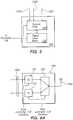
- Figure 6Aillustrates a transceiver 116n having a tunable receive signal path in accordance with an embodiment of the present invention.
- the transceiver 116nincludes a tunable duplexer 128 which is coupled to the antenna 106n. Signals received by the antenna 106n are allowed to pass through the duplexer 128 and a receiver 130 before being passed to other elements of the hub 102 via line 122n.
- the receiver 130may perform filtering and frequency down-converting of the received signal.
- the receive signal pathincluding the duplexer 128 and receiver 130, are tunable under control of the controller 118 depending upon whether the system is in listening mode or normal mode.
- a transmitter 132may be disabled by the controller 118 during listening mode. In normal mode, the transmitter 132 may perform such functions as signal filtering and frequency up-conversion.
- the transceivers 116a-nmay include an alternative signal path for listening mode.
- Figure 6Billustrates a transceiver 116n having an alternative receive signal path in accordance with an embodiment of the present invention.
- the transceiver 116nincludes a duplexer 128, a receiver 130 and a transmitter 132.
- the receiver 130receives signals from the antenna 106n via the duplexer 128 and the transmitter 132 sends signals to the antenna 106n via the duplexer 128.
- the receiver 130is configured to receive signals within the frequency range assigned to the uplink.
- the transceiver 116nincludes an alternative signal path through a second receiver 134.
- the second receiver 134is configured to receive signals within the frequency range assigned to the downlink.
- the second receiver 134may be coupled to the transmit side of the duplexer 128 for receiving signals from the duplexer 128 during listening mode. This is because the duplexer 128 is configured such that its transmit side will pass the range of frequencies assigned to the downlink. During listening mode, the received signals are also within the downlink frequencies.
- the output of the receiver 134is coupled to the receive signal path at the output of the receiver 130.
- the controller 118disables the receive signal path by disabling the receiver 130 and enables the alternative receive signal path by enabling the receiver 134.
- the receive signal pathis enabled by enabling the receiver 130, while the alternative receive signal path is disabled by disabling the receiver 134.
- the second receiver 134may be coupled to the antenna 106n.
- the alternative receive signal pathbypasses the duplexer 128.
- the second receiver 134may include a filter between the antenna 106a and its receive circuitry.
- each remote antenna 106a-nis preferably measured separately.
- the distributed antenna system 100may then report the results to the base station 104, to a server coupled to the distributed antenna system 100 or to some other location via the cellular telecommunication network to which the base station 104 is connected.
- a determination of which transmission frequency (including downlink and uplink pair) is be used by the distributed antenna system 100 while in normal modemay be determined automatically based on the reported results. This automatic determination may be performed by the base station 104 or by a server coupled to the distributed antenna system 100.
- a human operatormay review the results and determine which transmission frequency is to be used by the distributed antenna system 100 when in normal mode.
- the transmission frequencymay be determined by the controller 118. In this case, the distributed antenna system 100 may not report the results, but may simply adopt the self-determined transmission frequency.
- Results determined during listening modemay be reported in the form of a table.
- the controller 118may generate and report the table.
- Table 1shows an exemplary table which may be reported during listening mode.
- Table 1shows measured field strengths related to each antenna 106a-n. Particularly, Table 1 includes a row for each antenna 108a-n. Included in the row for a particular antenna is the measured field strength measurements for each frequency (or frequencies) for which the measurements are taken. As shown in Table 1, the frequencies at which the field strength measurements are taken for each antenna unit are given as F 1 , F 2 , F 3 , ...F N while the corresponding field strength measurements are given as A 1 , A 2 , A 3 , ... A N .
- the transmission frequency selected for use by the distributed antenna system 100 during normal modeis preferably one that is not being used by any of the overlapping cells of the cellular network 200 ( Figures 2 and 3 ).
- the frequency selected for use by the distributed antenna system 100may be one that is being used by an overlapping cell. For example, during listening mode, it may be discovered that a particular frequency is being used by a nearby cell, but that the signal is only received weakly by a limited number of the antennas 106a-n. In this case, it can be expected that if the antennas 106a-n are located indoors, any interference will be minimal.
- the distributed antenna system 100may be configured so that a particular one or more of the antennas 106a-n transmits at a lower power. These particular antennas 106a-n are selected to be those whose coverage area overlaps the coverage area of a cell of the network 200. This may be accomplished by the controller 118 causing the transceivers 116a-n corresponding to the particular antennas to transmit at the lower power.
- the distributed antenna system 100switches from normal mode to listening mode in response to an information message.
- the base station 104may send a message to the controller 118 of the distributed antenna system 100 instructing the distributed antenna system 100 to switch from normal mode to listening mode.
- a servermay be connected to the controller 118 through an Ethernet connection; in this case, an operator or software at the server may send the message.
- Such a messagemay also identify a frequency band in which the distributed antenna system 100 is to listen and possibly the channels within the band.
- the controller 118may instruct the transceivers 116a-n to tune to frequencies in the specified frequency band.
- the distributed antenna system 100may receive a second message instructing the distributed antenna system 100 to switch back to normal mode.
- This second messagemay also include information which is used to configure the distributed antenna system 100 for normal mode.
- This informationmay include the identification of a frequency pair to be used by the distributed antenna system 100 for the downlink and uplink signaling with the mobile devices 108a-n ( Figure 1 ).
- the distributed antenna system 100may the enter listening mode upon being powered on. Then, once the appropriate information is gathered in listening mode, the distributed antenna system 100 may switch back to normal mode.
- the distributed antenna system 100may default to the listening mode unless it detects a communication signal from its connected base station 104. More particularly, when the distributed antenna system 100 does not detect any communications signal from the base station 104, it may default to the listening mode. Then, in response to the distributed antenna system 100 detecting a communications signal from the base station 104, the distributed antenna system 100 switches to the normal mode. During the listening mode, taking of the field strength measurements may performed under control of the base station 104. In this embodiment, the field strength meter 120 may be included in the base station 104 rather than in the hub 102.
- the base station 104may take its field strength measurements from the combined signal received from all of the antennas 106a-n. The base station 104 may then inform the distributed antenna system 100 of the frequency pair to be used by the distributed antenna system 100 for normal mode before the base station 104 commences transmitting in normal mode.
- the base station 104may include signal metering capability. In this case, the base station 104 may perform the field strength measurements.
- Figure 7illustrates a distributed antenna communications system 300 and a base station 104 having signal metering capabilities.
- the base station 104is coupled to the hub 102, which is, in turn, coupled to multiple antennas 106a-n.
- the system 300operates in a normal mode, in which the antennas 106a-n perform bi-directional communications with mobile units and, in a listening mode, in which the system 300 determines whether there is any overlap with cells of the network 200 ( Figures 2 and 3 ).
- the base station 104is configured to listen to the downlink frequencies of the neighboring base stations 108a-n.
- the base station 104may measure the field strength of the combined signal. The base station 104 may then perform signal field strength measurements and instruct the hub 102 to configure its transceivers 116a-n to operate in an appropriate downlink frequency. Alternatively, the base station 104 may send the results to a server or to a human operator via the connected cellular telecommunication network, as described above in connection with Figure 4 .
- the embodiment of Figure 7preferably enters and exits listening mode without requiring signaling between the hub 102 and base station 104.
- the hub 102may default to the listening mode unless it detects a communication signal from its connected base station 104. Then, in response to the hub 102 detecting a communications signal from the base station 104, it may switch to the normal mode.
- the hub 102is reconfigured to transmit frequencies assigned to the downlink to the base station 104 ( Figures 1 and 4 ) so that the base station 104 can perform the field strength measurements.
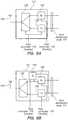
- the transceiver 112 of the hub 102may include a tunable transmit signal path which can be tuned to the downlink frequencies during listening mode.
- Figure 8Aillustrates a transceiver 112 having a tunable transmit signal path in accordance with an embodiment of the present invention. As shown in Figure 8A , the transceiver 112 includes a tunable transmitter 136 and a tunable duplexer 138.
- the duplexer 138is coupled to an antenna 140 which is used to communicate with the base station 140.
- Signals received from the distributed antennas 116a-nare passed through other elements of the hub 102 (e.g. the distribution node 114) and then to the transmitter 136.
- the transmitter 136may perform such functions as signal filtering and frequency up-conversion.
- the signal from the transmitter 136is then forwarded to the base station 104 via the duplexer 138 and antenna 140.
- the transmit signal path, including the transmitter 136 and duplexer 138are tunable under control of the controller 118 depending upon whether the system is in listening mode or normal mode.
- a receiver 142which is used for the downlink during normal mode, may be disabled by the controller 118 during listening mode. In normal mode, the receiver 142 may perform such functions as signal filtering and frequency down-conversion.
- the transceiver 112may include an alternative signal path for listening mode.
- Figure 8Billustrates a transceiver 112 having an alternative transmit signal path in accordance with an embodiment of the present invention.
- the transceiver 112includes a duplexer 138, a a transmitter 136 and a receiver 142.
- the transmitter 136sends uplink signals to the base station 104 via the duplexer 138 and antenna 140 while the receiver 142 receives downlink signals from the base station 104 via the antenna 140 and the duplexer 138.
- the transceiver 136is configured to transmit signals within the frequency range assigned to the uplink.
- the transceiver 112includes an alternative signal path through a second transmitter 144.
- the second transmitter 144is configured to transmit signals within the frequency range assigned to the downlink.
- the second transmitter 144may be coupled to the receive side of the duplexer 138 for transmitting signals via the duplexer 138 during listening mode. This is because the duplexer 138 is configured such that its receive side will pass the range of frequencies assigned to the downlink. During listening mode, the signals to be transmitted to the base station 104 are also within the downlink frequencies.
- the input of the transmitter 144is coupled to the transmit signal path at the input of the transmitter 136.
- the controller 118disables the transmit signal path by disabling the transmitter 136 and enables the alternative transmit signal path by enabling the transmitter 144.
- the transmit signal pathis enabled by enabling the transmitter 136, while the alternative transmit signal path is disabled by disabling the transmitter 144.
- the second transmitter 144may be coupled to the antenna 140.
- the alternative transmit signal pathbypasses the duplexer 138.
- the second transmitter 144may include a filter between the antenna 140 and its transmit circuitry.
- the transceiver 112may be coupled to the base station via two separate signal paths (e.g., separate cables) each carrying signals in one direction only.
- the tunable transceiver 136 of Figure 8Amay be coupled to either one of the separate signal paths between the hub 102 and the base station 104.
- the alternative transmit signal path of Figure 8Bmay be coupled to either one of the separate signal paths between the hub 102 and the base station 104.
Landscapes
- Engineering & Computer Science (AREA)
- Computer Networks & Wireless Communication (AREA)
- Signal Processing (AREA)
- Mobile Radio Communication Systems (AREA)
Description
- The present invention relates to the field of wireless communications and, more particularly, to distributed antenna systems for wireless communications.
- A conventional wireless cellular telecommunication network is comprised of multiple overlapping coverage areas or "cells." Mobile units (e.g. cellular telephones) travel from cell to cell while communicating via the network. Handovers between cells occur when the mobile units travel from one cell to another.
- Each cell is formed by a base transceiver station (BTS or "base station"). A typical base station comprises multiple transceivers and antennas for sending radio signals to the mobile units within the cell (downlink) and for receiving radio signals from the mobile units within the cell (uplink). Base stations are strategically located so as to maximize communications coverage over large geographical areas. The base stations are communicatively coupled to the cellular telecommunication network via backhaul connections.
- The cellular telecommunication network may also include base station controllers (BSCs) and mobile switching centers (MSCs). Several base stations may be under the control of a single BSC. The BSC generally functions as a signal concentrator, allocates radio channels to mobile units and controls handovers from base station to base station. The BSC is, in turn, coupled to an MSC. The MSC generally functions as a telephone exchange to provide circuit switching functionality. The MSC is coupled to a public switched telecommunication network (PSTN) for voice communications and may also be coupled the Internet for data communications.
- To prevent interference between the uplink and downlink signaling within each cell, different communication frequencies are used for the uplink and the downlink within each cell. In addition, to prevent interference among adjacent cells, the communication frequencies used within each cell differ from those of adjacent cells.
- Due to the need to avoid interference with adjacent cells and other factors, installation and set-up of such cellular networks as well as the integration of new equipment to an existing cellular network can be complex and time consuming.
- Further, such cellular telecommunication networks can experience difficulties due to indoor penetration loss. For example, if a mobile unit is located indoors, an additional indoor penetration loss of 8dB to 30dB is common. A distributed antenna system (DAS) can be used to provide indoor coverage for wireless communications. In such a DAS, transmitted power is divided among several antennas in distributed locations so as to provide a large coverage area using less transmitted power than would be required by a single antenna system.
- As with other equipment, the integration of a distributed antenna system to an existing cellular network can be complex and time consuming. Therefore, there is a need for an improved system for and method of configuring a distributed antenna system.
US 2005/0176368A describes a distributed adaptive repeater system which includes a donor unit, two or more coverage units (CUs), and an intelligent hub. The donor unit operates to maintain bidirectional wireless communication with a base station of a wireless communications network. Each coverage unit maintains bidirectional wireless communication with transceivers located within a respective coverage area, and is further adapted to independently control a signal path to ensure stability of a respective feedback loop to the donor unit. The intelligent hub is operatively coupled between the donor unit and the coverage units, and adapted to monitor a status of each coverage unit.US 5,884,145 describes an allocation method and system for allocating a least-interference communications channel between a cellular system and a private radio system within the cellular system. A set of candidate channels are first selected and ordered by the amount of interference present within the cellular system, and a subset thereof is selected. A second set of candidate channels are then selected from the subset and ordered by the amount of interference present in the private radio system environment, and a safe channel subset thereof is selected. That channel exhibiting the least amount of interference is then selected from the safe channel subset as the communications channel.- Aspects of the present invention are set out in the appended independent claim.
- The present invention provides a system for and method of configuring a distributed antenna system. In accordance with an embodiment of the invention, a distributed antenna system comprises a plurality of antennas and a multi-port hub. The multi-port hub comprises an interface to a telecommunications network and a plurality of transceivers. The multi-port hub is configured to operate in a first mode ("normal" mode) in which the multi-port hub receives a downlink communications signal via the interface and distributes the downlink communications signal to the plurality of antennas using a selected downlink transmission frequency within a downlink frequency range and in which the multi-port hub receives uplink communications signals from the plurality of antennas at a selected uplink receive frequency. The multi-port hub is also configured to operate in a second mode ("listening" mode) in which the multi-port hub receives communications signals from the plurality of antennas and the meter measures the field strength of each of the signals at a plurality of frequencies. The transmission frequency for the first mode ("normal" mode) may be selected based on measured field strength of the signals received in the second mode ("listening" mode).
- The present invention is described with respect to particular exemplary embodiments thereof and reference is accordingly made to the drawings in which:
Figure 1 illustrates a distributed antenna communications system configured for communication with mobile units in accordance with an embodiment of the present invention;Figure 2 illustrates cellular coverage areas of a cellular telecommunication network in which the distributed antenna system ofFigure 1 may be deployed in accordance with an embodiment of the present invention;Figure 3 illustrates a distributed antenna system being deployed in the cellular network ofFigure 2 in accordance with an embodiment of the present invention;Figure 4 illustrates a distributed antenna communications system being configured for deployment in a cellular network in accordance with an embodiment of the present invention;Figure 5 illustrates a signal field strength meter in accordance with an embodiment of the present invention;Figures 6A-B illustrate a transceiver for interfacing with mobile units in accordance with embodiments of the present invention;Figure 7 illustrates a distributed antenna communications system and base station having signal metering capability in accordance with an embodiment of the present invention; andFigures 8A-B illustrate a transceiver for interfacing with a base station having signal metering capability in accordance with embodiments of the present invention.Figure 1 illustrates a distributedantenna communications system 100 in accordance with an embodiment of the present invention. Thesystem 100 includes acommunications hub 102, and a plurality ofdistributed antennas 106a-n coupled to ports of thehub 102. Abase transceiver station 104 is communicatively coupled to thehub 102. In addition, one or moremobile communications devices 108a-n are communicatively coupled to thehub 102 via theantennas 106a-n. Thebase station 104 may be located at the site of a cellular service provider and may be coupled to a cellular telecommunication network via abackhaul 110. Thehub 102 may be located at the premises of a telecommunications subscriber with theantennas 106a-n being distributed throughout the premises. For example, thehub 102 may be located within a building (e.g., in a utility room) with the antennas distributed throughout the building so as to provide indoor coverage areas formobile devices 108a-n. Themobile devices 108a-n may be, for example, cell phones. While threemobile devices 108a-n and threeantennas 106a-n are illustrated, it will be apparent that more or fewer of either may be present. In an embodiment, up to eightantennas 106a-n may be coupled to asingle hub 102. Additionally, one or more of theantennas 106a-n may be located outdoors.- Rather than locating the
base station 104 at a remote location from thehub 102, as shown inFigure 1 , thebase station 104 andhub 102 may be co-located. For example, functionality of thebase station 104 may be integrated with that of thehub 102 into a single piece of equipment located at the subscriber premises. - The
system 100 preferably provides for two-way communications. For the downlink, telecommunications signals are received by thebase station 104 from the cellular telecommunication network and distributed to theantennas 106a-n. To accomplish this, atransceiver 112 may receive the downlink signal from thebase station 104. Thetransceiver 112 then amplifies the downlink signal to an appropriate level for forwarding to adistribution node 114. Thedistribution node 114 then repeats and distributes the signal to a plurality oftransceivers 116a-n such that each of thetransceivers 116a-n receives a copy of the downlink signal. Thetransceivers 116a-n each transmit the signal received from thedistribution node 114 via a corresponding one of theantennas 106a-n. Themobile devices 108a-n each pick up the downlink signal from one or more of theantennas 106a-n. - For the uplink, signals from the
mobile devices 108a-n are received by thetransceivers 116a-n via theantennas 106a-n. The signals are then forwarded to thedistribution node 114 which combines the signals (e.g., by simple summation) into a combined signal. The combined signal is transmitted to thebase station 104 by thetransceiver 112. Thebase station 104 then forwards the combined signal to the cellular telecommunication network. - In an embodiment, the downlink signal from the
base station 104 is RF (Radio Frequency). For example, this signal is communicated via a cable or via a wireless link between thetransceiver 112 and thebase station 104. In this case, thetransceiver 112 may down-convert the downlink signal from RF to IF. This signal is then distributed to thetransceivers 116a-n in IF. Thetransceivers 116a-n up-convert the IF signal to RF (Radio Frequency) before transmitting the signal to themobile devices 108a-n. For the uplink, thetransceivers 116a-n down-convert RF signals received from themobile devices 108a-n to IF. These IF signals are then processed and combined for delivery to thetransceiver 112 in IF. Thetransceiver 112 then up-converts the IF signal to RF for delivery thebase station 104. Accordingly, thetransceiver 112 functions as an interface to the telephone network via thebase station 104. - So that multiple
mobile devices 108a-n may communicate via thesystem 100 simultaneously, each communicates in a different channel. For example, CDMA (Code-Division, Multiple Access) protocols for cellular communication, such as UMTS (Universal Mobile Telecommunications System), or TDMA (Time-Division, Multiple-Access) protocols for cellular communication, such as GSM (Global System for Mobile Communications) may be employed by thesystem 100. Thus, for the downlink, the same signal including the various channels is transmitted via each of theantennas 106a-n so that it may be received by any of themobile devices 108a-n without regard to which of theantennas 106a-n is closest to a particular one of the mobile devices. For the up-link, the signal from a particular mobile device may be picked up by one ormore antennas 106a-n. As shown inFigure 1 , the signal fromdevice 108a is picked up byantennas Figure 1 , the signal fromdevice 108b is picked up only byantenna 106n. The signal fromdevice 108n is also picked up only by theantenna 106n. All of the signals picked up by any of theantennas 106a-n are combined atnode 114 and included in the combined signal received at thebase station 104. Thehub 102 may also include acontroller 118 and ameter 120, whose functions are described in more detail herein. Figure 2 illustratescellular coverage areas 202A-F or "cells" of acellular telecommunication network 200 in which the distributedantenna system 100 ofFigure 1 may be deployed. Each of thecells 202A-F is roughly centered about a corresponding one ofbase stations 204A-F. While six such cells are shown, it will be apparent that a cellular network could be comprised of a different number of cells. For example, a large cellular network may comprise tens or even hundreds of cells which provide coverage for a large geographical area. In this case, many of the cells may be completely surrounded by adjacent neighbor cells.Figure 3 illustrates the distributedantenna system 100 being deployed in thecellular network 200 ofFigure 2 . As shown inFigure 3 , the distributedantenna system 100 forms acoverage area 206. Thecoverage area 206 is shown having an irregular shape because theantennas 106a-n (Figure 1 ) may be positioned in various different locations. In addition, one or more of theantennas 106a-n may be located within a building, the structure of which will tend to attenuate signal strength.- Because the
coverage area 206 of the distributedantenna system 100 may overlap one or more of thecells 202A-F of thecellular network 200, it is possible for interference to occur between the distributedantenna system 100 and one or more of the cells of thecellular network 200. To avoid this, the distributedantenna system 100 is preferably configured so as to avoid employing any of the communication frequencies that are used by those cells of thenetwork 200 whose coverage areas overlap that of the distributedantenna system 100 unless the signal strength of the cells of thenetwork 200 in the overlapping coverage area is sufficiently low that interference is unlikely. - Referring again to
Figure 1 , normal operation of the distributedantenna system 100 is shown. In this mode of operation, which may be referred to as "normal" mode, the distributedantenna system 100 transmits signals via thetransceivers 116a-n using transmission frequencies assigned to the downlink signaling direction. The distributedantenna system 100 also receives signals via thetransceivers 116a-n in frequencies assigned to the uplink signaling direction. The normal mode is used for facilitating communications for themobile units 108a-n. While the distributedantenna system 100 is operating in normal mode, thebase stations 204A-F of the cellular network 200 (shown inFigures 2 and 3 ) also transmit signals using downlink frequencies. Thebase stations 204A-F also receive signals in frequencies assigned to the uplink signaling direction. Therefore, thebase stations 204A-F and the distributedantenna system 100 may interfere with one another by attempting to transmit different information at the same frequency and in the same area. However, thebase stations 204A-F and the distributedantenna system 100 would not "see" each other because they are each configured to only receive signals assigned to the uplink signaling direction. Figure 4 illustrates the distributedantenna communications system 100 being configured for deployment in thecellular network 200 in accordance with an embodiment of the present invention. As shown inFigure 4 , thetransceivers 116a-n are configured to receive signals in frequency bands transmitted by thebase stations 204A-F (downlink frequencies). Therefore, in this mode of operation, which may be referred to as "listening" or "mobile" mode, thetransceivers 116a-n are configured to receive signals assigned to the downlink signaling direction. In this mode, however, the distributedantenna system 100 may be unable to facilitate communications with themobile units 108a-n because themobile units 108a-n only transmit in frequencies assigned to the uplink signaling direction.- In the listening mode, the distributed
antenna system 100 detects signals from thebase stations 204A-F of thecellular network 200 by listening for their downlink signals. This is used to identify downlink frequencies used by thebase stations 204A-F which might interfere with transmissions by the distributedantenna system 100. Interference is then avoided by selecting transmission frequencies for use by the distributedantenna system 100 in normal mode that differ from those whose signal strength detected during listening mode is sufficiently strong that interference is likely to occur. - To enter listening mode, the
controller 118 may instruct thetransceivers 116a-n of the distributedantenna system 100 to tune their receive frequencies to correspond to the frequencies assigned to the downlink signaling direction. For example, the distributedantenna system 100 may be configured to operate in a specific frequency band containing several frequency channels. In this case, thetransceivers 116a-n may be tuned to a first one of the channels within the band. In addition, thetransceivers 116a-n may be instructed to cease transmitting. - The
meter 120 is coupled tolines 122a-n from each of thetransceivers 116a-n. During listening mode, themeter 120 monitors the received signals vialines 122a-n to determine their levels and, thus, field strengths received atantennas 106a-n. Because thetransceivers 116a-n may initially be tuned to the first frequency channel within the band, themeter 120 may first determine the field strength for the first frequency channel. Themeter 120 may simultaneously monitor all of thelines 122a-n or, alternatively, themeter 120 may cycle through thelines 122a-n, measuring the field strengths on thelines 122a-n one-at-a-time. Thetransceivers 116a-n may then be tuned to the next frequency channel in the band so that the field strength measurements may be taken for that frequency channel. This process may be continued until the field strength for each frequency channel within the band is measured for each of thetransceivers 116a-n. Rather than measuring the field strength for a frequency channel for all of thetransceivers 106a-n and then measuring the field strength for a next channel, the field strength for all of the channels may be measured for a single transceiver before measuring the field strength for all of the channels for the next transceiver. In other words, the order in which the field strength measurements are taken may vary. - Once the field strength values are determined for the signals received from the
base stations 204A-F of thecellular network 200, this information may be used to configure thetransceivers 116a-n to transmit using a frequency that differs from any of those identified as having a field strength that sufficiently strong that interference is likely. For example, the distributedantenna system 100 may be configured to transmit using a specified channel within a frequency band. In this way, interference between the distributedantenna system 100 and any overlapping cells of thecellular network 100 is avoided. The distributedantenna system 100 may then enter normal mode in which the selected transmission frequency is used. Selection of a transmission frequency for the downlink will typically also involve selecting a paired receive frequency for the uplink. - If the distributed
antenna system 100 supports multiple frequency bands, such as 900 MHz and 1800 MHz, the distributedantenna system 100 may monitor each of the bands while in listening mode. This may be accomplished by tuning thetransceivers 116a-n to one of the bands first, and then to another, until all the bands have been monitored. If the distributedantenna system 100 supports multiple bands, such 900 MHz or 1800 MHz, but is able to operate in only one band at a time, it may be unnecessary to detect frequencies in all of the bands. This is because the distributedantenna system 100 need only avoid interference in the bands in which it is actually operating. In this case, a human operator may configure the distributedantenna system 100 to select its operating band. Alternatively, the distributedantenna system 100 may automatically select the most-recent frequency band that used by the distributedantenna system 100 or that was used by thebase station 104 for monitoring in listening mode. - As described above, the
transceivers 116a-n are tunable to the various channels within a frequency band (i.e. the transceivers are channelized). In an alternative embodiment, thetransceivers 116a-n may be tuned to simultaneously receive several frequencies within a band (i.e. the transceivers are broadband). In this case, themeter 120 may be provided with a tunable filter in order to obtain field strength measurements for each channel.Figure 5 illustrates thefield strength meter 120 in accordance with an embodiment of the present invention. As shown inFigure 5 , themeter 120 includes atunable filter 124 which is coupled to each of thelines 122a-n. Thetunable filter 124 is controlled by thecontroller 118 to tune to each channel. Asignal level meter 126 is coupled to thetunable filter 124 to obtain the field strength measurements and to report them to thecontroller 118. - For listening mode, the
transceivers 116a-n are reconfigured to receive frequencies assigned to the downlink. In an embodiment, thetransceivers 116a-n include an tunable receive signal path which can be tuned to the downlink frequencies.Figure 6A illustrates atransceiver 116n having a tunable receive signal path in accordance with an embodiment of the present invention. As shown inFigure 6A , thetransceiver 116n includes atunable duplexer 128 which is coupled to theantenna 106n. Signals received by theantenna 106n are allowed to pass through theduplexer 128 and areceiver 130 before being passed to other elements of thehub 102 vialine 122n. Thereceiver 130 may perform filtering and frequency down-converting of the received signal. As shown inFigure 6A , the receive signal path, including theduplexer 128 andreceiver 130, are tunable under control of thecontroller 118 depending upon whether the system is in listening mode or normal mode. In addition, atransmitter 132 may be disabled by thecontroller 118 during listening mode. In normal mode, thetransmitter 132 may perform such functions as signal filtering and frequency up-conversion. - In an alternative embodiment, rather than the
transceivers 116a-n including a tunable receive signal path as inFigure 6A , thetransceivers 116a-n may include an alternative signal path for listening mode.Figure 6B illustrates atransceiver 116n having an alternative receive signal path in accordance with an embodiment of the present invention. As shown inFigure 6B , thetransceiver 116n includes aduplexer 128, areceiver 130 and atransmitter 132. During normal mode, thereceiver 130 receives signals from theantenna 106n via theduplexer 128 and thetransmitter 132 sends signals to theantenna 106n via theduplexer 128. Thereceiver 130 is configured to receive signals within the frequency range assigned to the uplink. In addition, thetransceiver 116n includes an alternative signal path through asecond receiver 134. Thesecond receiver 134 is configured to receive signals within the frequency range assigned to the downlink. - The
second receiver 134 may be coupled to the transmit side of theduplexer 128 for receiving signals from theduplexer 128 during listening mode. This is because theduplexer 128 is configured such that its transmit side will pass the range of frequencies assigned to the downlink. During listening mode, the received signals are also within the downlink frequencies. The output of thereceiver 134 is coupled to the receive signal path at the output of thereceiver 130. To reconfigure thetransceiver 116n ofFigure 6B for listening mode, thecontroller 118 disables the receive signal path by disabling thereceiver 130 and enables the alternative receive signal path by enabling thereceiver 134. To return to normal mode, the receive signal path is enabled by enabling thereceiver 130, while the alternative receive signal path is disabled by disabling thereceiver 134. - Rather than the
second receiver 134 being coupled to the transmit side of theduplexer 128 as shown inFigure 6B , thesecond receiver 134 may be coupled to theantenna 106n. In this embodiment, the alternative receive signal path bypasses theduplexer 128. Also, in this embodiment, thesecond receiver 134 may include a filter between theantenna 106a and its receive circuitry. - When the distributed
antenna system 100 is in listening mode, eachremote antenna 106a-n is preferably measured separately. The distributedantenna system 100 may then report the results to thebase station 104, to a server coupled to the distributedantenna system 100 or to some other location via the cellular telecommunication network to which thebase station 104 is connected. A determination of which transmission frequency (including downlink and uplink pair) is be used by the distributedantenna system 100 while in normal mode may be determined automatically based on the reported results. This automatic determination may be performed by thebase station 104 or by a server coupled to the distributedantenna system 100. Alternatively, a human operator may review the results and determine which transmission frequency is to be used by the distributedantenna system 100 when in normal mode. In still another embodiment, the transmission frequency may be determined by thecontroller 118. In this case, the distributedantenna system 100 may not report the results, but may simply adopt the self-determined transmission frequency. - Results determined during listening mode may be reported in the form of a table. For example, the
controller 118 may generate and report the table. Table 1 below shows an exemplary table which may be reported during listening mode. Table 1 shows measured field strengths related to eachantenna 106a-n. Particularly, Table 1 includes a row for eachantenna 108a-n. Included in the row for a particular antenna is the measured field strength measurements for each frequency (or frequencies) for which the measurements are taken. As shown in Table 1, the frequencies at which the field strength measurements are taken for each antenna unit are given as F1, F2, F3, ...FN while the corresponding field strength measurements are given as A1, A2, A3, ... AN. If no signal is detected by a particular antenna for a particular frequency, this information is also recorded in the table, e.g. as no entry or Ø. It will be apparent that Table 1 is exemplary and that the results may be arranged differently.Field Strength(s) Antenna Unit F1, F2, F3, ... F N108a A1, A2, A3, ... AN 108b A1, A2, A3, ... AN : : 108n A1, A2, A3,... AN - As mentioned, the transmission frequency selected for use by the distributed
antenna system 100 during normal mode is preferably one that is not being used by any of the overlapping cells of the cellular network 200 (Figures 2 and 3 ). However, in an embodiment, the frequency selected for use by the distributedantenna system 100 may be one that is being used by an overlapping cell. For example, during listening mode, it may be discovered that a particular frequency is being used by a nearby cell, but that the signal is only received weakly by a limited number of theantennas 106a-n. In this case, it can be expected that if theantennas 106a-n are located indoors, any interference will be minimal. To further reduce the potential for interference in such a situation, the distributedantenna system 100 may be configured so that a particular one or more of theantennas 106a-n transmits at a lower power. Theseparticular antennas 106a-n are selected to be those whose coverage area overlaps the coverage area of a cell of thenetwork 200. This may be accomplished by thecontroller 118 causing thetransceivers 116a-n corresponding to the particular antennas to transmit at the lower power. - In accordance with an embodiment of the invention, the distributed
antenna system 100 switches from normal mode to listening mode in response to an information message. For example, thebase station 104 may send a message to thecontroller 118 of the distributedantenna system 100 instructing the distributedantenna system 100 to switch from normal mode to listening mode. Alternatively, rather than receiving the message from thebase station 104, a server may be connected to thecontroller 118 through an Ethernet connection; in this case, an operator or software at the server may send the message. Such a message may also identify a frequency band in which the distributedantenna system 100 is to listen and possibly the channels within the band. In response to the message, thecontroller 118 may instruct thetransceivers 116a-n to tune to frequencies in the specified frequency band. - Once the appropriate information is gathered in listening mode, the distributed
antenna system 100 may receive a second message instructing the distributedantenna system 100 to switch back to normal mode. This second message may also include information which is used to configure the distributedantenna system 100 for normal mode. This information may include the identification of a frequency pair to be used by the distributedantenna system 100 for the downlink and uplink signaling with themobile devices 108a-n (Figure 1 ). - Rather than entering the listening mode in response to a message, the distributed
antenna system 100 may the enter listening mode upon being powered on. Then, once the appropriate information is gathered in listening mode, the distributedantenna system 100 may switch back to normal mode. - In an embodiment, the distributed
antenna system 100 may default to the listening mode unless it detects a communication signal from its connectedbase station 104. More particularly, when the distributedantenna system 100 does not detect any communications signal from thebase station 104, it may default to the listening mode. Then, in response to the distributedantenna system 100 detecting a communications signal from thebase station 104, the distributedantenna system 100 switches to the normal mode. During the listening mode, taking of the field strength measurements may performed under control of thebase station 104. In this embodiment, thefield strength meter 120 may be included in thebase station 104 rather than in thehub 102. In addition, during listening mode, rather than measuring the signal received by each antenna separately, thebase station 104 may take its field strength measurements from the combined signal received from all of theantennas 106a-n. Thebase station 104 may then inform the distributedantenna system 100 of the frequency pair to be used by the distributedantenna system 100 for normal mode before thebase station 104 commences transmitting in normal mode. - As mentioned, the
base station 104 may include signal metering capability. In this case, thebase station 104 may perform the field strength measurements.Figure 7 illustrates a distributedantenna communications system 300 and abase station 104 having signal metering capabilities. Thebase station 104 is coupled to thehub 102, which is, in turn, coupled tomultiple antennas 106a-n. As before, thesystem 300 operates in a normal mode, in which theantennas 106a-n perform bi-directional communications with mobile units and, in a listening mode, in which thesystem 300 determines whether there is any overlap with cells of the network 200 (Figures 2 and 3 ). In the listening mode, thebase station 104 is configured to listen to the downlink frequencies of the neighboringbase stations 108a-n. Because the signals from each of the distributedantennas 106a-n are combined by thehub 102, thebase station 104 may measure the field strength of the combined signal. Thebase station 104 may then perform signal field strength measurements and instruct thehub 102 to configure itstransceivers 116a-n to operate in an appropriate downlink frequency. Alternatively, thebase station 104 may send the results to a server or to a human operator via the connected cellular telecommunication network, as described above in connection withFigure 4 . - The embodiment of
Figure 7 preferably enters and exits listening mode without requiring signaling between thehub 102 andbase station 104. As described above, thehub 102 may default to the listening mode unless it detects a communication signal from its connectedbase station 104. Then, in response to thehub 102 detecting a communications signal from thebase station 104, it may switch to the normal mode. - In the embodiment of
Figure 7 , for listening mode, thehub 102 is reconfigured to transmit frequencies assigned to the downlink to the base station 104 (Figures 1 and4 ) so that thebase station 104 can perform the field strength measurements. To accomplish this, thetransceiver 112 of thehub 102 may include a tunable transmit signal path which can be tuned to the downlink frequencies during listening mode.Figure 8A illustrates atransceiver 112 having a tunable transmit signal path in accordance with an embodiment of the present invention. As shown inFigure 8A , thetransceiver 112 includes atunable transmitter 136 and atunable duplexer 138. Theduplexer 138 is coupled to anantenna 140 which is used to communicate with thebase station 140. Signals received from the distributedantennas 116a-n are passed through other elements of the hub 102 (e.g. the distribution node 114) and then to thetransmitter 136. Thetransmitter 136 may perform such functions as signal filtering and frequency up-conversion. The signal from thetransmitter 136 is then forwarded to thebase station 104 via theduplexer 138 andantenna 140. As shown inFigure 8A , the transmit signal path, including thetransmitter 136 andduplexer 138 are tunable under control of thecontroller 118 depending upon whether the system is in listening mode or normal mode. In addition, areceiver 142 which is used for the downlink during normal mode, may be disabled by thecontroller 118 during listening mode. In normal mode, thereceiver 142 may perform such functions as signal filtering and frequency down-conversion. - In an alternative embodiment, rather than the
transceiver 112 including a tunable transmit signal path as inFigure 8A , thetransceiver 112 may include an alternative signal path for listening mode.Figure 8B illustrates atransceiver 112 having an alternative transmit signal path in accordance with an embodiment of the present invention. As shown inFigure 8B , thetransceiver 112 includes aduplexer 138,a a transmitter 136 and areceiver 142. During normal mode, thetransmitter 136 sends uplink signals to thebase station 104 via theduplexer 138 andantenna 140 while thereceiver 142 receives downlink signals from thebase station 104 via theantenna 140 and theduplexer 138. Thetransceiver 136 is configured to transmit signals within the frequency range assigned to the uplink. In addition, thetransceiver 112 includes an alternative signal path through asecond transmitter 144. Thesecond transmitter 144 is configured to transmit signals within the frequency range assigned to the downlink. - The
second transmitter 144 may be coupled to the receive side of theduplexer 138 for transmitting signals via theduplexer 138 during listening mode. This is because theduplexer 138 is configured such that its receive side will pass the range of frequencies assigned to the downlink. During listening mode, the signals to be transmitted to thebase station 104 are also within the downlink frequencies. The input of thetransmitter 144 is coupled to the transmit signal path at the input of thetransmitter 136. To reconfigure thetransceiver 112 ofFigure 8B for listening mode, thecontroller 118 disables the transmit signal path by disabling thetransmitter 136 and enables the alternative transmit signal path by enabling thetransmitter 144. To return to normal mode, the transmit signal path is enabled by enabling thetransmitter 136, while the alternative transmit signal path is disabled by disabling thetransmitter 144. - Rather than the
second transmitter 144 being coupled to the receive side of theduplexer 138 as shown inFigure 8B , thesecond transmitter 144 may be coupled to theantenna 140. In this embodiment, the alternative transmit signal path bypasses theduplexer 138. Also, in this embodiment, thesecond transmitter 144 may include a filter between theantenna 140 and its transmit circuitry. - Additionally, rather than employing the
duplexer 138 as inFigures 8A and 8B for bi-directional communication between thehub 102 andbase station 104, thetransceiver 112 may be coupled to the base station via two separate signal paths (e.g., separate cables) each carrying signals in one direction only. In this case, thetunable transceiver 136 ofFigure 8A may be coupled to either one of the separate signal paths between thehub 102 and thebase station 104. Similarly, the alternative transmit signal path ofFigure 8B may be coupled to either one of the separate signal paths between thehub 102 and thebase station 104. - The foregoing detailed description of the present invention is provided for the purposes of illustration and is not intended to be exhaustive or to limit the invention to the embodiments disclosed. Accordingly, the scope of the present invention is defined by the appended claims.
Claims (21)
- A distributed antenna system (100) comprising:a plurality of antennas (106); anda multi-port hub (102) comprising an interface (112) to a telecommunications network and a plurality of transceivers (116), wherein the multi-port hub (102) is configured to operate in a first mode in which the multi-port hub (102) receives a downlink communications signal via the interface (112) and distributes the downlink communications signal to the plurality of antennas (106) using a selected downlink transmission frequency within a downlink frequency range and in which the multi-port hub (102) receives uplink communications signals from the plurality of antennas (106) at a selected uplink receive frequency;wherein each of the plurality of antennas (106) is located remotely from the multi-port hub (102);characterised in that:the multi-port hub (102) is configured to operate in a second mode in which the multi-port hub (102) receives communications signals from the plurality of antennas (106) at one or more frequencies within the downlink frequency range.
- The distributed antenna system (100) according to claim 1, wherein each transceiver (116) is configurable to transmit at a selected transmission frequency and wherein the transmission frequency for the first mode is selected based on measured field strength of the signals received in the second mode.
- The distributed antenna system (100) according to claim 1, wherein the multi-port hub (102) enters the second mode in response to detecting the absence of a signal from the interface (112).
- The distributed antenna system (100) according to claim 3, wherein the multi-port hub (102) enters the first mode in response to the signal being detected at the interface (112).
- The distributed antenna system (100) according to claim 1, further comprising a meter (120) for measuring field strength of signals received by the antennas (106).
- The distributed antenna system (100) according to claim 5, the meter (120) being located in a base station (104) coupled to the distributed antenna system (100) via the interface (112).
- The distributed antenna system (100) according to claim 1, wherein one or more of the transceivers (116) further comprises a tunable receive signal path for receiving the uplink communications signals in the first mode and for receiving the communications signals at one or more frequencies within the downlink frequency range in the second mode.
- The distributed antenna system (100) according to claim 1, wherein one or more of the transceivers (116) further comprises first and second receive signal paths, the first path for receiving the uplink communications signals in the first mode and the second path for receiving the communications signals at one or more frequencies within the downlink frequency range in the second mode.
- The distributed antenna system (100) according to claim 1, wherein the interface (112) further comprises a tunable transmit signal path for transmitting the uplink communications signals to the telecommunications network in the first mode and for transmitting the communications signals at one or more frequencies within the downlink frequency range to the telecommunications network in the second mode.
- The distributed antenna system (100) according to claim 1, wherein the interface (112) further comprises first and second transmit signal paths, the first path for transmitting the uplink communications signals to the telecommunications network in the first mode and the second path for transmitting the communications signals at one or more frequencies within the downlink frequency range to the telecommunications network in the second mode.
- The distributed antenna system (100) according to claim 1, wherein in the first mode, the distributed antenna system (100) receives uplink communications signals from one or more mobile units (108).
- The distributed antenna system (100) according to claim 11, wherein in the second mode, the distributed antenna system receives downlink communications from one or more nearby base transceiver stations (204) of a cellular network.
- The distributed antenna system (100) according to claim 1, wherein the multi-port hub (102) enters the second mode in response to receiving a message.
- The distributed antenna system (100) according to claim5, further comprising a base transceiver station (104) coupled to the multi-port hub (102) via the interface (112) wherein the base transceiver (104) station includes the meter.
- The distributed antenna system (100) according to claim 1, wherein the transmission and receive frequencies used in the first mode are selected to avoid using any frequency detected during the second mode.
- The distributed antenna system (100) according to claim 1, wherein the transmission frequency used in the first mode is the same as a frequency detected at one or more of the antennas (106) during the second mode and wherein the transmit power for those antennas (106) is adjusted lower than the remaining antennas (106).
- The distributed antenna system (100) according to claim 1, wherein the distributed antenna system (100) measures multiple different frequency bands in the second mode, each frequency band comprising a plurality of channel frequencies for which field strength measurements are taken.
- The distributed antenna system (100) according to claim 1, wherein the transceivers (116) are reconfigurable to operate in the first and second modes by comprising a frequency tunable receive signal path.
- The distributed antenna system (100) according to claim 1, wherein the transceivers (116) are reconfigurable to operate in the first and second modes by comprising a receive signal path for operation in the second mode and an alternative receive signal path for operation in the first mode.
- The distributed antenna system (100) according to claim 1, wherein the transceivers (116) are tuned to each of the plurality of frequencies in the first mode.
- The distributed antenna system (100) according to claim 5, wherein the transceivers (116) are tuned to a frequency band including each of the plurality of frequencies and wherein a tunable filter (124) is coupled to the meter (126) and selectively tuned to each of the plurality of frequencies in the first mode.
Applications Claiming Priority (2)
| Application Number | Priority Date | Filing Date | Title |
|---|---|---|---|
| US11/897,728US9112547B2 (en) | 2007-08-31 | 2007-08-31 | System for and method of configuring distributed antenna communications system |
| PCT/US2007/023518WO2009029077A1 (en) | 2007-08-31 | 2007-11-08 | System for and method of configuring distributed antenna communications system |
Publications (3)
| Publication Number | Publication Date |
|---|---|
| EP2186206A1 EP2186206A1 (en) | 2010-05-19 |
| EP2186206A4 EP2186206A4 (en) | 2013-01-02 |
| EP2186206B1true EP2186206B1 (en) | 2017-08-30 |
Family
ID=40387586
Family Applications (1)
| Application Number | Title | Priority Date | Filing Date |
|---|---|---|---|
| EP07861832.9AActiveEP2186206B1 (en) | 2007-08-31 | 2007-11-08 | System for and method of configuring distributed antenna communications system |
Country Status (5)
| Country | Link |
|---|---|
| US (1) | US9112547B2 (en) |
| EP (1) | EP2186206B1 (en) |
| CN (1) | CN101842995B (en) |
| CA (1) | CA2697787C (en) |
| WO (1) | WO2009029077A1 (en) |
Families Citing this family (222)
| Publication number | Priority date | Publication date | Assignee | Title |
|---|---|---|---|---|
| WO2009034614A1 (en)* | 2007-09-11 | 2009-03-19 | Fujitsu Limited | Wireless base station and method for controlling the same |
| US8977219B2 (en)* | 2010-09-30 | 2015-03-10 | Broadcom Corporation | Method and system for mitigating leakage of a 60 GHz transmitted signal back into an RF input of a 60 GHz device |
| US9008593B2 (en) | 2010-09-30 | 2015-04-14 | Broadcom Corporation | Method and system for 60 GHz distributed communication |
| US8942647B2 (en)* | 2010-09-30 | 2015-01-27 | Broadcom Corporation | Method and system for antenna switching for 60 GHz distributed communication |
| US8942645B2 (en)* | 2010-09-30 | 2015-01-27 | Broadcom Corporation | Method and system for communication via subbands in a 60 GHZ distributed communication system |
| US9002300B2 (en)* | 2010-09-30 | 2015-04-07 | Broadcom Corporation | Method and system for time division duplexing (TDD) in a 60 GHZ distributed communication system |
| US8942646B2 (en)* | 2010-09-30 | 2015-01-27 | Broadcom Corporation | Method and system for a 60 GHz communication device comprising multi-location antennas for pseudo-beamforming |
| ATE543261T1 (en)* | 2008-02-19 | 2012-02-15 | Nxp Bv | SOFTWARE DEFINED RADIO DEVICE |
| US8346278B2 (en) | 2009-01-13 | 2013-01-01 | Adc Telecommunications, Inc. | Systems and methods for mobile phone location with digital distributed antenna systems |
| USRE47466E1 (en) | 2009-01-13 | 2019-06-25 | Commscope Technologies Llc | Systems and methods for IP communication over a distributed antenna system transport |
| US8213401B2 (en) | 2009-01-13 | 2012-07-03 | Adc Telecommunications, Inc. | Systems and methods for IP communication over a distributed antenna system transport |
| US9673904B2 (en) | 2009-02-03 | 2017-06-06 | Corning Optical Communications LLC | Optical fiber-based distributed antenna systems, components, and related methods for calibration thereof |
| CN102396171B (en) | 2009-02-03 | 2015-09-30 | 康宁光缆系统有限责任公司 | Based on the distributing antenna system of optical fiber, assembly and the correlation technique for monitoring and configure distributing antenna system based on optical fiber, assembly |
| US8280259B2 (en) | 2009-11-13 | 2012-10-02 | Corning Cable Systems Llc | Radio-over-fiber (RoF) system for protocol-independent wired and/or wireless communication |
| US8275265B2 (en) | 2010-02-15 | 2012-09-25 | Corning Cable Systems Llc | Dynamic cell bonding (DCB) for radio-over-fiber (RoF)-based networks and communication systems and related methods |
| DE102010018492B4 (en) | 2010-04-28 | 2011-12-08 | Andrew Wireless Systems Gmbh | Interface module for a unit of an antenna distribution system and antenna distribution system |
| AU2011274307B2 (en) | 2010-06-29 | 2016-07-14 | Commonwealth Scientific And Industrial Research Organisation | Dynamic network configuration |
| US8472579B2 (en) | 2010-07-28 | 2013-06-25 | Adc Telecommunications, Inc. | Distributed digital reference clock |
| US9042838B2 (en)* | 2010-08-25 | 2015-05-26 | Intel Corporation | Transmit leakage cancellation in a wide bandwidth distributed antenna system |
| US9252874B2 (en) | 2010-10-13 | 2016-02-02 | Ccs Technology, Inc | Power management for remote antenna units in distributed antenna systems |
| US8532242B2 (en) | 2010-10-27 | 2013-09-10 | Adc Telecommunications, Inc. | Distributed antenna system with combination of both all digital transport and hybrid digital/analog transport |
| JP5432882B2 (en)* | 2010-11-25 | 2014-03-05 | 株式会社日立製作所 | Distributed antenna system, distributed antenna switching method, base station apparatus, and antenna switch apparatus |
| WO2012148940A1 (en) | 2011-04-29 | 2012-11-01 | Corning Cable Systems Llc | Systems, methods, and devices for increasing radio frequency (rf) power in distributed antenna systems |
| WO2012148938A1 (en) | 2011-04-29 | 2012-11-01 | Corning Cable Systems Llc | Determining propagation delay of communications in distributed antenna systems, and related components, systems and methods |
| EP2715947B1 (en) | 2011-06-01 | 2018-08-15 | CommScope Technologies LLC | Broadband distributed antenna system with non-duplexer isolator sub-system |
| EP2719138B1 (en) | 2011-06-09 | 2020-05-20 | CommScope Technologies LLC | Distributed antenna system interface for processing digital signals in a standardized format |
| CN102281548A (en)* | 2011-08-01 | 2011-12-14 | 深圳市云海通讯股份有限公司 | Frequency domain decomposition-long term evolution (FDD-LTE) indoor coverage system |
| AU2012302074B2 (en) | 2011-08-29 | 2017-02-16 | Commscope Technologies Llc | Configuring a distributed antenna system |
| US9270346B2 (en)* | 2011-12-02 | 2016-02-23 | Apple Inc. | Methods for operating wireless electronic devices in coordinated multipoint transmission networks |
| US8254848B1 (en)* | 2011-12-09 | 2012-08-28 | At&T Intellectual Property I, Lp | Monitoring system for distributed antenna systems |
| EP3422589B1 (en)* | 2012-02-02 | 2024-07-24 | CommScope Technologies LLC | Optimized telecommunications distribution system |
| EP2829152A2 (en) | 2012-03-23 | 2015-01-28 | Corning Optical Communications Wireless Ltd. | Radio-frequency integrated circuit (rfic) chip(s) for providing distributed antenna system functionalities, and related components, systems, and methods |
| WO2013162988A1 (en) | 2012-04-25 | 2013-10-31 | Corning Cable Systems Llc | Distributed antenna system architectures |
| US9306682B2 (en) | 2012-07-20 | 2016-04-05 | Commscope Technologies Llc | Systems and methods for a self-optimizing distributed antenna system |
| DE202013012858U1 (en) | 2012-08-09 | 2021-05-07 | Axel Wireless Ltd. | Capacity-centered digital distributed antenna system |
| US9913147B2 (en) | 2012-10-05 | 2018-03-06 | Andrew Wireless Systems Gmbh | Capacity optimization sub-system for distributed antenna system |
| US9455784B2 (en) | 2012-10-31 | 2016-09-27 | Corning Optical Communications Wireless Ltd | Deployable wireless infrastructures and methods of deploying wireless infrastructures |
| US9113347B2 (en) | 2012-12-05 | 2015-08-18 | At&T Intellectual Property I, Lp | Backhaul link for distributed antenna system |
| US10009065B2 (en) | 2012-12-05 | 2018-06-26 | At&T Intellectual Property I, L.P. | Backhaul link for distributed antenna system |
| US9832739B2 (en) | 2013-01-08 | 2017-11-28 | Whoop Wireless Llc | System and method for calibration of a distributed amplifier system |
| CA2914104C (en) | 2013-02-22 | 2022-12-13 | Adc Telecommunications, Inc. | Master reference for base station network interface sourced from distributed antenna system |
| US9999038B2 (en) | 2013-05-31 | 2018-06-12 | At&T Intellectual Property I, L.P. | Remote distributed antenna system |
| US9525524B2 (en) | 2013-05-31 | 2016-12-20 | At&T Intellectual Property I, L.P. | Remote distributed antenna system |
| US9247543B2 (en) | 2013-07-23 | 2016-01-26 | Corning Optical Communications Wireless Ltd | Monitoring non-supported wireless spectrum within coverage areas of distributed antenna systems (DASs) |
| US8897697B1 (en) | 2013-11-06 | 2014-11-25 | At&T Intellectual Property I, Lp | Millimeter-wave surface-wave communications |
| US9209902B2 (en) | 2013-12-10 | 2015-12-08 | At&T Intellectual Property I, L.P. | Quasi-optical coupler |
| TW201524141A (en)* | 2013-12-13 | 2015-06-16 | Amoesolu Corp | Distributed antenna system |
| US9178635B2 (en) | 2014-01-03 | 2015-11-03 | Corning Optical Communications Wireless Ltd | Separation of communication signal sub-bands in distributed antenna systems (DASs) to reduce interference |
| US10251154B2 (en) | 2014-02-18 | 2019-04-02 | Commscope Technologies Llc | Distributed antenna system measurement receiver |
| WO2015126520A1 (en) | 2014-02-21 | 2015-08-27 | Commscope Technologies Llc | Optimizing network resources in a telecommunications system |
| US9705609B2 (en) | 2014-04-15 | 2017-07-11 | Commscope Technologies Llc | Wideband remote unit for distributed antenna system |
| US9357551B2 (en) | 2014-05-30 | 2016-05-31 | Corning Optical Communications Wireless Ltd | Systems and methods for simultaneous sampling of serial digital data streams from multiple analog-to-digital converters (ADCS), including in distributed antenna systems |
| US9692101B2 (en) | 2014-08-26 | 2017-06-27 | At&T Intellectual Property I, L.P. | Guided wave couplers for coupling electromagnetic waves between a waveguide surface and a surface of a wire |
| US9768833B2 (en) | 2014-09-15 | 2017-09-19 | At&T Intellectual Property I, L.P. | Method and apparatus for sensing a condition in a transmission medium of electromagnetic waves |
| US10063280B2 (en) | 2014-09-17 | 2018-08-28 | At&T Intellectual Property I, L.P. | Monitoring and mitigating conditions in a communication network |
| CA2961696A1 (en) | 2014-09-23 | 2016-03-31 | Axell Wireless Ltd. | Automatic mapping and handling pim and other uplink interferences in digital distributed antenna systems |
| US9628854B2 (en) | 2014-09-29 | 2017-04-18 | At&T Intellectual Property I, L.P. | Method and apparatus for distributing content in a communication network |
| US9615269B2 (en) | 2014-10-02 | 2017-04-04 | At&T Intellectual Property I, L.P. | Method and apparatus that provides fault tolerance in a communication network |
| US9685992B2 (en) | 2014-10-03 | 2017-06-20 | At&T Intellectual Property I, L.P. | Circuit panel network and methods thereof |
| US9503189B2 (en) | 2014-10-10 | 2016-11-22 | At&T Intellectual Property I, L.P. | Method and apparatus for arranging communication sessions in a communication system |
| US9973299B2 (en) | 2014-10-14 | 2018-05-15 | At&T Intellectual Property I, L.P. | Method and apparatus for adjusting a mode of communication in a communication network |
| US9762289B2 (en) | 2014-10-14 | 2017-09-12 | At&T Intellectual Property I, L.P. | Method and apparatus for transmitting or receiving signals in a transportation system |
| US9627768B2 (en) | 2014-10-21 | 2017-04-18 | At&T Intellectual Property I, L.P. | Guided-wave transmission device with non-fundamental mode propagation and methods for use therewith |
| US9577306B2 (en) | 2014-10-21 | 2017-02-21 | At&T Intellectual Property I, L.P. | Guided-wave transmission device and methods for use therewith |
| US9769020B2 (en) | 2014-10-21 | 2017-09-19 | At&T Intellectual Property I, L.P. | Method and apparatus for responding to events affecting communications in a communication network |
| US9653770B2 (en) | 2014-10-21 | 2017-05-16 | At&T Intellectual Property I, L.P. | Guided wave coupler, coupling module and methods for use therewith |
| US9520945B2 (en) | 2014-10-21 | 2016-12-13 | At&T Intellectual Property I, L.P. | Apparatus for providing communication services and methods thereof |
| US9312919B1 (en) | 2014-10-21 | 2016-04-12 | At&T Intellectual Property I, Lp | Transmission device with impairment compensation and methods for use therewith |
| US9780834B2 (en) | 2014-10-21 | 2017-10-03 | At&T Intellectual Property I, L.P. | Method and apparatus for transmitting electromagnetic waves |
| US9564947B2 (en) | 2014-10-21 | 2017-02-07 | At&T Intellectual Property I, L.P. | Guided-wave transmission device with diversity and methods for use therewith |
| US9997819B2 (en) | 2015-06-09 | 2018-06-12 | At&T Intellectual Property I, L.P. | Transmission medium and method for facilitating propagation of electromagnetic waves via a core |
| US9800327B2 (en) | 2014-11-20 | 2017-10-24 | At&T Intellectual Property I, L.P. | Apparatus for controlling operations of a communication device and methods thereof |
| US9544006B2 (en) | 2014-11-20 | 2017-01-10 | At&T Intellectual Property I, L.P. | Transmission device with mode division multiplexing and methods for use therewith |
| US9954287B2 (en) | 2014-11-20 | 2018-04-24 | At&T Intellectual Property I, L.P. | Apparatus for converting wireless signals and electromagnetic waves and methods thereof |
| US9461706B1 (en) | 2015-07-31 | 2016-10-04 | At&T Intellectual Property I, Lp | Method and apparatus for exchanging communication signals |
| US10340573B2 (en) | 2016-10-26 | 2019-07-02 | At&T Intellectual Property I, L.P. | Launcher with cylindrical coupling device and methods for use therewith |
| US10243784B2 (en) | 2014-11-20 | 2019-03-26 | At&T Intellectual Property I, L.P. | System for generating topology information and methods thereof |
| US9680670B2 (en) | 2014-11-20 | 2017-06-13 | At&T Intellectual Property I, L.P. | Transmission device with channel equalization and control and methods for use therewith |
| US9742462B2 (en) | 2014-12-04 | 2017-08-22 | At&T Intellectual Property I, L.P. | Transmission medium and communication interfaces and methods for use therewith |
| US9654173B2 (en) | 2014-11-20 | 2017-05-16 | At&T Intellectual Property I, L.P. | Apparatus for powering a communication device and methods thereof |
| US10009067B2 (en) | 2014-12-04 | 2018-06-26 | At&T Intellectual Property I, L.P. | Method and apparatus for configuring a communication interface |
| EP3238352A4 (en) | 2014-12-23 | 2018-08-22 | Axell Wireless Ltd. | Harmonizing noise aggregation and noise management in distributed antenna system |
| US10144036B2 (en) | 2015-01-30 | 2018-12-04 | At&T Intellectual Property I, L.P. | Method and apparatus for mitigating interference affecting a propagation of electromagnetic waves guided by a transmission medium |
| US20160249365A1 (en) | 2015-02-19 | 2016-08-25 | Corning Optical Communications Wireless Ltd. | Offsetting unwanted downlink interference signals in an uplink path in a distributed antenna system (das) |
| US9876570B2 (en) | 2015-02-20 | 2018-01-23 | At&T Intellectual Property I, Lp | Guided-wave transmission device with non-fundamental mode propagation and methods for use therewith |
| US9980318B2 (en) | 2015-03-16 | 2018-05-22 | Commscope Technologies Llc | DAS management by radio access network node |
| US9749013B2 (en) | 2015-03-17 | 2017-08-29 | At&T Intellectual Property I, L.P. | Method and apparatus for reducing attenuation of electromagnetic waves guided by a transmission medium |
| US9681313B2 (en) | 2015-04-15 | 2017-06-13 | Corning Optical Communications Wireless Ltd | Optimizing remote antenna unit performance using an alternative data channel |
| KR20160123866A (en)* | 2015-04-17 | 2016-10-26 | 주식회사 쏠리드 | Node unit of distributed antenna system |
| US9705561B2 (en) | 2015-04-24 | 2017-07-11 | At&T Intellectual Property I, L.P. | Directional coupling device and methods for use therewith |
| US10224981B2 (en) | 2015-04-24 | 2019-03-05 | At&T Intellectual Property I, Lp | Passive electrical coupling device and methods for use therewith |
| US9793954B2 (en) | 2015-04-28 | 2017-10-17 | At&T Intellectual Property I, L.P. | Magnetic coupling device and methods for use therewith |
| US9948354B2 (en) | 2015-04-28 | 2018-04-17 | At&T Intellectual Property I, L.P. | Magnetic coupling device with reflective plate and methods for use therewith |
| US9766324B2 (en)* | 2015-05-06 | 2017-09-19 | Microsoft Technology Licensing, Llc | Multiple antenna communication system configured to detect objects |
| US9871282B2 (en) | 2015-05-14 | 2018-01-16 | At&T Intellectual Property I, L.P. | At least one transmission medium having a dielectric surface that is covered at least in part by a second dielectric |
| US9748626B2 (en) | 2015-05-14 | 2017-08-29 | At&T Intellectual Property I, L.P. | Plurality of cables having different cross-sectional shapes which are bundled together to form a transmission medium |
| US9490869B1 (en) | 2015-05-14 | 2016-11-08 | At&T Intellectual Property I, L.P. | Transmission medium having multiple cores and methods for use therewith |
| US10650940B2 (en) | 2015-05-15 | 2020-05-12 | At&T Intellectual Property I, L.P. | Transmission medium having a conductive material and methods for use therewith |
| US10679767B2 (en) | 2015-05-15 | 2020-06-09 | At&T Intellectual Property I, L.P. | Transmission medium having a conductive material and methods for use therewith |
| US9917341B2 (en) | 2015-05-27 | 2018-03-13 | At&T Intellectual Property I, L.P. | Apparatus and method for launching electromagnetic waves and for modifying radial dimensions of the propagating electromagnetic waves |
| US10103801B2 (en) | 2015-06-03 | 2018-10-16 | At&T Intellectual Property I, L.P. | Host node device and methods for use therewith |
| US10348391B2 (en) | 2015-06-03 | 2019-07-09 | At&T Intellectual Property I, L.P. | Client node device with frequency conversion and methods for use therewith |
| US10154493B2 (en) | 2015-06-03 | 2018-12-11 | At&T Intellectual Property I, L.P. | Network termination and methods for use therewith |
| US10812174B2 (en) | 2015-06-03 | 2020-10-20 | At&T Intellectual Property I, L.P. | Client node device and methods for use therewith |
| US9866309B2 (en) | 2015-06-03 | 2018-01-09 | At&T Intellectual Property I, Lp | Host node device and methods for use therewith |
| US9912381B2 (en) | 2015-06-03 | 2018-03-06 | At&T Intellectual Property I, Lp | Network termination and methods for use therewith |
| US9913139B2 (en) | 2015-06-09 | 2018-03-06 | At&T Intellectual Property I, L.P. | Signal fingerprinting for authentication of communicating devices |
| US9608692B2 (en) | 2015-06-11 | 2017-03-28 | At&T Intellectual Property I, L.P. | Repeater and methods for use therewith |
| US10142086B2 (en) | 2015-06-11 | 2018-11-27 | At&T Intellectual Property I, L.P. | Repeater and methods for use therewith |
| US20160366657A1 (en)* | 2015-06-11 | 2016-12-15 | Collision Communications, Inc. | Methods, Systems, And Computer Program Products For Over The Air Synchronization For Cellular Networks |
| US9820146B2 (en) | 2015-06-12 | 2017-11-14 | At&T Intellectual Property I, L.P. | Method and apparatus for authentication and identity management of communicating devices |
| US9667317B2 (en) | 2015-06-15 | 2017-05-30 | At&T Intellectual Property I, L.P. | Method and apparatus for providing security using network traffic adjustments |
| US9640850B2 (en) | 2015-06-25 | 2017-05-02 | At&T Intellectual Property I, L.P. | Methods and apparatus for inducing a non-fundamental wave mode on a transmission medium |
| US9509415B1 (en) | 2015-06-25 | 2016-11-29 | At&T Intellectual Property I, L.P. | Methods and apparatus for inducing a fundamental wave mode on a transmission medium |
| US9865911B2 (en) | 2015-06-25 | 2018-01-09 | At&T Intellectual Property I, L.P. | Waveguide system for slot radiating first electromagnetic waves that are combined into a non-fundamental wave mode second electromagnetic wave on a transmission medium |
| US9882257B2 (en) | 2015-07-14 | 2018-01-30 | At&T Intellectual Property I, L.P. | Method and apparatus for launching a wave mode that mitigates interference |
| US10320586B2 (en) | 2015-07-14 | 2019-06-11 | At&T Intellectual Property I, L.P. | Apparatus and methods for generating non-interfering electromagnetic waves on an insulated transmission medium |
| US9853342B2 (en) | 2015-07-14 | 2017-12-26 | At&T Intellectual Property I, L.P. | Dielectric transmission medium connector and methods for use therewith |
| US9847566B2 (en) | 2015-07-14 | 2017-12-19 | At&T Intellectual Property I, L.P. | Method and apparatus for adjusting a field of a signal to mitigate interference |
| US10341142B2 (en) | 2015-07-14 | 2019-07-02 | At&T Intellectual Property I, L.P. | Apparatus and methods for generating non-interfering electromagnetic waves on an uninsulated conductor |
| US10205655B2 (en) | 2015-07-14 | 2019-02-12 | At&T Intellectual Property I, L.P. | Apparatus and methods for communicating utilizing an antenna array and multiple communication paths |
| US10033108B2 (en) | 2015-07-14 | 2018-07-24 | At&T Intellectual Property I, L.P. | Apparatus and methods for generating an electromagnetic wave having a wave mode that mitigates interference |
| US10170840B2 (en) | 2015-07-14 | 2019-01-01 | At&T Intellectual Property I, L.P. | Apparatus and methods for sending or receiving electromagnetic signals |
| US9722318B2 (en) | 2015-07-14 | 2017-08-01 | At&T Intellectual Property I, L.P. | Method and apparatus for coupling an antenna to a device |
| US10033107B2 (en) | 2015-07-14 | 2018-07-24 | At&T Intellectual Property I, L.P. | Method and apparatus for coupling an antenna to a device |
| US9836957B2 (en) | 2015-07-14 | 2017-12-05 | At&T Intellectual Property I, L.P. | Method and apparatus for communicating with premises equipment |
| US10148016B2 (en) | 2015-07-14 | 2018-12-04 | At&T Intellectual Property I, L.P. | Apparatus and methods for communicating utilizing an antenna array |
| US10044409B2 (en) | 2015-07-14 | 2018-08-07 | At&T Intellectual Property I, L.P. | Transmission medium and methods for use therewith |
| US9628116B2 (en) | 2015-07-14 | 2017-04-18 | At&T Intellectual Property I, L.P. | Apparatus and methods for transmitting wireless signals |
| US10090606B2 (en) | 2015-07-15 | 2018-10-02 | At&T Intellectual Property I, L.P. | Antenna system with dielectric array and methods for use therewith |
| US9608740B2 (en) | 2015-07-15 | 2017-03-28 | At&T Intellectual Property I, L.P. | Method and apparatus for launching a wave mode that mitigates interference |
| US9793951B2 (en) | 2015-07-15 | 2017-10-17 | At&T Intellectual Property I, L.P. | Method and apparatus for launching a wave mode that mitigates interference |
| US9948349B2 (en) | 2015-07-17 | 2018-04-17 | Corning Optical Communications Wireless Ltd | IOT automation and data collection system |
| US10784670B2 (en) | 2015-07-23 | 2020-09-22 | At&T Intellectual Property I, L.P. | Antenna support for aligning an antenna |
| US9749053B2 (en) | 2015-07-23 | 2017-08-29 | At&T Intellectual Property I, L.P. | Node device, repeater and methods for use therewith |
| US9948333B2 (en) | 2015-07-23 | 2018-04-17 | At&T Intellectual Property I, L.P. | Method and apparatus for wireless communications to mitigate interference |
| US9912027B2 (en) | 2015-07-23 | 2018-03-06 | At&T Intellectual Property I, L.P. | Method and apparatus for exchanging communication signals |
| US9871283B2 (en) | 2015-07-23 | 2018-01-16 | At&T Intellectual Property I, Lp | Transmission medium having a dielectric core comprised of plural members connected by a ball and socket configuration |
| US9967173B2 (en) | 2015-07-31 | 2018-05-08 | At&T Intellectual Property I, L.P. | Method and apparatus for authentication and identity management of communicating devices |
| US9735833B2 (en) | 2015-07-31 | 2017-08-15 | At&T Intellectual Property I, L.P. | Method and apparatus for communications management in a neighborhood network |
| US10020587B2 (en) | 2015-07-31 | 2018-07-10 | At&T Intellectual Property I, L.P. | Radial antenna and methods for use therewith |
| US9904535B2 (en) | 2015-09-14 | 2018-02-27 | At&T Intellectual Property I, L.P. | Method and apparatus for distributing software |
| US10079661B2 (en) | 2015-09-16 | 2018-09-18 | At&T Intellectual Property I, L.P. | Method and apparatus for use with a radio distributed antenna system having a clock reference |
| US10051629B2 (en) | 2015-09-16 | 2018-08-14 | At&T Intellectual Property I, L.P. | Method and apparatus for use with a radio distributed antenna system having an in-band reference signal |
| US10009063B2 (en) | 2015-09-16 | 2018-06-26 | At&T Intellectual Property I, L.P. | Method and apparatus for use with a radio distributed antenna system having an out-of-band reference signal |
| US9705571B2 (en) | 2015-09-16 | 2017-07-11 | At&T Intellectual Property I, L.P. | Method and apparatus for use with a radio distributed antenna system |
| US10136434B2 (en) | 2015-09-16 | 2018-11-20 | At&T Intellectual Property I, L.P. | Method and apparatus for use with a radio distributed antenna system having an ultra-wideband control channel |
| US10009901B2 (en) | 2015-09-16 | 2018-06-26 | At&T Intellectual Property I, L.P. | Method, apparatus, and computer-readable storage medium for managing utilization of wireless resources between base stations |
| US9769128B2 (en) | 2015-09-28 | 2017-09-19 | At&T Intellectual Property I, L.P. | Method and apparatus for encryption of communications over a network |
| US9729197B2 (en) | 2015-10-01 | 2017-08-08 | At&T Intellectual Property I, L.P. | Method and apparatus for communicating network management traffic over a network |
| US9876264B2 (en) | 2015-10-02 | 2018-01-23 | At&T Intellectual Property I, Lp | Communication system, guided wave switch and methods for use therewith |
| US9882277B2 (en) | 2015-10-02 | 2018-01-30 | At&T Intellectual Property I, Lp | Communication device and antenna assembly with actuated gimbal mount |
| US10074890B2 (en) | 2015-10-02 | 2018-09-11 | At&T Intellectual Property I, L.P. | Communication device and antenna with integrated light assembly |
| US10665942B2 (en) | 2015-10-16 | 2020-05-26 | At&T Intellectual Property I, L.P. | Method and apparatus for adjusting wireless communications |
| US10355367B2 (en) | 2015-10-16 | 2019-07-16 | At&T Intellectual Property I, L.P. | Antenna structure for exchanging wireless signals |
| US10051483B2 (en) | 2015-10-16 | 2018-08-14 | At&T Intellectual Property I, L.P. | Method and apparatus for directing wireless signals |
| US10499269B2 (en) | 2015-11-12 | 2019-12-03 | Commscope Technologies Llc | Systems and methods for assigning controlled nodes to channel interfaces of a controller |
| US9479244B1 (en)* | 2015-11-25 | 2016-10-25 | At&T Intellectual Propery I, L.P. | Radio frequency repeater system for signal transmission through radio frequency shielding material in connected home applications |
| US10236924B2 (en) | 2016-03-31 | 2019-03-19 | Corning Optical Communications Wireless Ltd | Reducing out-of-channel noise in a wireless distribution system (WDS) |
| US9912419B1 (en) | 2016-08-24 | 2018-03-06 | At&T Intellectual Property I, L.P. | Method and apparatus for managing a fault in a distributed antenna system |
| US9860075B1 (en) | 2016-08-26 | 2018-01-02 | At&T Intellectual Property I, L.P. | Method and communication node for broadband distribution |
| US10291311B2 (en) | 2016-09-09 | 2019-05-14 | At&T Intellectual Property I, L.P. | Method and apparatus for mitigating a fault in a distributed antenna system |
| US11032819B2 (en) | 2016-09-15 | 2021-06-08 | At&T Intellectual Property I, L.P. | Method and apparatus for use with a radio distributed antenna system having a control channel reference signal |
| US10135147B2 (en) | 2016-10-18 | 2018-11-20 | At&T Intellectual Property I, L.P. | Apparatus and methods for launching guided waves via an antenna |
| US10135146B2 (en) | 2016-10-18 | 2018-11-20 | At&T Intellectual Property I, L.P. | Apparatus and methods for launching guided waves via circuits |
| US10340600B2 (en) | 2016-10-18 | 2019-07-02 | At&T Intellectual Property I, L.P. | Apparatus and methods for launching guided waves via plural waveguide systems |
| US9991580B2 (en) | 2016-10-21 | 2018-06-05 | At&T Intellectual Property I, L.P. | Launcher and coupling system for guided wave mode cancellation |
| US10811767B2 (en) | 2016-10-21 | 2020-10-20 | At&T Intellectual Property I, L.P. | System and dielectric antenna with convex dielectric radome |
| US9876605B1 (en) | 2016-10-21 | 2018-01-23 | At&T Intellectual Property I, L.P. | Launcher and coupling system to support desired guided wave mode |
| US10374316B2 (en) | 2016-10-21 | 2019-08-06 | At&T Intellectual Property I, L.P. | System and dielectric antenna with non-uniform dielectric |
| US10312567B2 (en) | 2016-10-26 | 2019-06-04 | At&T Intellectual Property I, L.P. | Launcher with planar strip antenna and methods for use therewith |
| US10498044B2 (en) | 2016-11-03 | 2019-12-03 | At&T Intellectual Property I, L.P. | Apparatus for configuring a surface of an antenna |
| US10225025B2 (en) | 2016-11-03 | 2019-03-05 | At&T Intellectual Property I, L.P. | Method and apparatus for detecting a fault in a communication system |
| US10224634B2 (en) | 2016-11-03 | 2019-03-05 | At&T Intellectual Property I, L.P. | Methods and apparatus for adjusting an operational characteristic of an antenna |
| US10291334B2 (en) | 2016-11-03 | 2019-05-14 | At&T Intellectual Property I, L.P. | System for detecting a fault in a communication system |
| US10178445B2 (en) | 2016-11-23 | 2019-01-08 | At&T Intellectual Property I, L.P. | Methods, devices, and systems for load balancing between a plurality of waveguides |
| US10535928B2 (en) | 2016-11-23 | 2020-01-14 | At&T Intellectual Property I, L.P. | Antenna system and methods for use therewith |
| US10090594B2 (en) | 2016-11-23 | 2018-10-02 | At&T Intellectual Property I, L.P. | Antenna system having structural configurations for assembly |
| US10340603B2 (en) | 2016-11-23 | 2019-07-02 | At&T Intellectual Property I, L.P. | Antenna system having shielded structural configurations for assembly |
| US10340601B2 (en) | 2016-11-23 | 2019-07-02 | At&T Intellectual Property I, L.P. | Multi-antenna system and methods for use therewith |
| US10305190B2 (en) | 2016-12-01 | 2019-05-28 | At&T Intellectual Property I, L.P. | Reflecting dielectric antenna system and methods for use therewith |
| US10361489B2 (en) | 2016-12-01 | 2019-07-23 | At&T Intellectual Property I, L.P. | Dielectric dish antenna system and methods for use therewith |
| US10439675B2 (en) | 2016-12-06 | 2019-10-08 | At&T Intellectual Property I, L.P. | Method and apparatus for repeating guided wave communication signals |
| US10755542B2 (en) | 2016-12-06 | 2020-08-25 | At&T Intellectual Property I, L.P. | Method and apparatus for surveillance via guided wave communication |
| US9927517B1 (en) | 2016-12-06 | 2018-03-27 | At&T Intellectual Property I, L.P. | Apparatus and methods for sensing rainfall |
| US10382976B2 (en) | 2016-12-06 | 2019-08-13 | At&T Intellectual Property I, L.P. | Method and apparatus for managing wireless communications based on communication paths and network device positions |
| US10819035B2 (en) | 2016-12-06 | 2020-10-27 | At&T Intellectual Property I, L.P. | Launcher with helical antenna and methods for use therewith |
| US10020844B2 (en) | 2016-12-06 | 2018-07-10 | T&T Intellectual Property I, L.P. | Method and apparatus for broadcast communication via guided waves |
| US10727599B2 (en) | 2016-12-06 | 2020-07-28 | At&T Intellectual Property I, L.P. | Launcher with slot antenna and methods for use therewith |
| US10694379B2 (en) | 2016-12-06 | 2020-06-23 | At&T Intellectual Property I, L.P. | Waveguide system with device-based authentication and methods for use therewith |
| US10135145B2 (en) | 2016-12-06 | 2018-11-20 | At&T Intellectual Property I, L.P. | Apparatus and methods for generating an electromagnetic wave along a transmission medium |
| US10637149B2 (en) | 2016-12-06 | 2020-04-28 | At&T Intellectual Property I, L.P. | Injection molded dielectric antenna and methods for use therewith |
| US10326494B2 (en) | 2016-12-06 | 2019-06-18 | At&T Intellectual Property I, L.P. | Apparatus for measurement de-embedding and methods for use therewith |
| US10243270B2 (en) | 2016-12-07 | 2019-03-26 | At&T Intellectual Property I, L.P. | Beam adaptive multi-feed dielectric antenna system and methods for use therewith |
| US10389029B2 (en) | 2016-12-07 | 2019-08-20 | At&T Intellectual Property I, L.P. | Multi-feed dielectric antenna system with core selection and methods for use therewith |
| US10446936B2 (en) | 2016-12-07 | 2019-10-15 | At&T Intellectual Property I, L.P. | Multi-feed dielectric antenna system and methods for use therewith |
| US10139820B2 (en) | 2016-12-07 | 2018-11-27 | At&T Intellectual Property I, L.P. | Method and apparatus for deploying equipment of a communication system |
| US10547348B2 (en) | 2016-12-07 | 2020-01-28 | At&T Intellectual Property I, L.P. | Method and apparatus for switching transmission mediums in a communication system |
| US10359749B2 (en) | 2016-12-07 | 2019-07-23 | At&T Intellectual Property I, L.P. | Method and apparatus for utilities management via guided wave communication |
| US10168695B2 (en) | 2016-12-07 | 2019-01-01 | At&T Intellectual Property I, L.P. | Method and apparatus for controlling an unmanned aircraft |
| US9893795B1 (en) | 2016-12-07 | 2018-02-13 | At&T Intellectual Property I, Lp | Method and repeater for broadband distribution |
| US10027397B2 (en) | 2016-12-07 | 2018-07-17 | At&T Intellectual Property I, L.P. | Distributed antenna system and methods for use therewith |
| US10103422B2 (en) | 2016-12-08 | 2018-10-16 | At&T Intellectual Property I, L.P. | Method and apparatus for mounting network devices |
| US10530505B2 (en) | 2016-12-08 | 2020-01-07 | At&T Intellectual Property I, L.P. | Apparatus and methods for launching electromagnetic waves along a transmission medium |
| US10411356B2 (en) | 2016-12-08 | 2019-09-10 | At&T Intellectual Property I, L.P. | Apparatus and methods for selectively targeting communication devices with an antenna array |
| US10389037B2 (en) | 2016-12-08 | 2019-08-20 | At&T Intellectual Property I, L.P. | Apparatus and methods for selecting sections of an antenna array and use therewith |
| US9998870B1 (en) | 2016-12-08 | 2018-06-12 | At&T Intellectual Property I, L.P. | Method and apparatus for proximity sensing |
| US10938108B2 (en) | 2016-12-08 | 2021-03-02 | At&T Intellectual Property I, L.P. | Frequency selective multi-feed dielectric antenna system and methods for use therewith |
| US10069535B2 (en) | 2016-12-08 | 2018-09-04 | At&T Intellectual Property I, L.P. | Apparatus and methods for launching electromagnetic waves having a certain electric field structure |
| US10601494B2 (en) | 2016-12-08 | 2020-03-24 | At&T Intellectual Property I, L.P. | Dual-band communication device and method for use therewith |
| US10777873B2 (en) | 2016-12-08 | 2020-09-15 | At&T Intellectual Property I, L.P. | Method and apparatus for mounting network devices |
| US9911020B1 (en) | 2016-12-08 | 2018-03-06 | At&T Intellectual Property I, L.P. | Method and apparatus for tracking via a radio frequency identification device |
| US10326689B2 (en) | 2016-12-08 | 2019-06-18 | At&T Intellectual Property I, L.P. | Method and system for providing alternative communication paths |
| US10916969B2 (en) | 2016-12-08 | 2021-02-09 | At&T Intellectual Property I, L.P. | Method and apparatus for providing power using an inductive coupling |
| US10264586B2 (en) | 2016-12-09 | 2019-04-16 | At&T Mobility Ii Llc | Cloud-based packet controller and methods for use therewith |
| US9838896B1 (en) | 2016-12-09 | 2017-12-05 | At&T Intellectual Property I, L.P. | Method and apparatus for assessing network coverage |
| US10340983B2 (en) | 2016-12-09 | 2019-07-02 | At&T Intellectual Property I, L.P. | Method and apparatus for surveying remote sites via guided wave communications |
| US9973940B1 (en) | 2017-02-27 | 2018-05-15 | At&T Intellectual Property I, L.P. | Apparatus and methods for dynamic impedance matching of a guided wave launcher |
| US10298293B2 (en) | 2017-03-13 | 2019-05-21 | At&T Intellectual Property I, L.P. | Apparatus of communication utilizing wireless network devices |
| US20180351688A1 (en)* | 2017-06-05 | 2018-12-06 | J3 Technology LLC | Use of Cinder Block or Concrete to Re-Radiate an RF Signal |
| CN108736988B (en)* | 2018-05-22 | 2020-12-04 | Oppo广东移动通信有限公司 | Electronic device and control method thereof, and computer-readable storage medium |
| FR3105671A1 (en)* | 2019-12-20 | 2021-06-25 | Orange | A method of allocating radio signal transmission frequencies between one or more communication entities, allowing a reduction in interference between these communication entities using the same frequency channel |
Family Cites Families (203)
| Publication number | Priority date | Publication date | Assignee | Title |
|---|---|---|---|---|
| US37820A (en)* | 1863-03-03 | Improvement in hydrants | ||
| JPS5412766B2 (en)* | 1971-11-24 | 1979-05-25 | ||
| US4061981A (en)* | 1976-08-18 | 1977-12-06 | General Motors Corporation | Voltage variable capacitor tuned radio receiver having delayed automatic frequency control at turn-on |
| US4451916A (en)* | 1980-05-12 | 1984-05-29 | Harris Corporation | Repeatered, multi-channel fiber optic communication network having fault isolation system |
| NL8203600A (en)* | 1982-09-17 | 1984-04-16 | Philips Nv | MAIN END AND RECEIVER FOR A SIGNAL DISTRIBUTION SYSTEM. |
| US4691292A (en)* | 1983-04-13 | 1987-09-01 | Rca Corporation | System for digital multiband filtering |
| DE3318774A1 (en)* | 1983-05-24 | 1984-11-29 | ANT Nachrichtentechnik GmbH, 7150 Backnang | METHOD FOR TRANSMITTING DIGITALLY CODED ANALOG SIGNALS |
| US4628501A (en)* | 1983-12-29 | 1986-12-09 | The United States Of America As Represented By The Secretary Of The Army | Optical communications systems |
| US4667319A (en)* | 1985-07-29 | 1987-05-19 | Gte Sprint Communications Corporation | Digital repeater with 3-way branching of service channels |
| EP0215479B1 (en)* | 1985-09-18 | 1991-09-11 | Nec Corporation | One frequency repeater for a digital radio system |
| DE3578240D1 (en)* | 1985-12-04 | 1990-07-19 | Ibm | MULTIPLEX INTERFACE FOR A TRANSMISSION CONTROL. |
| GB2197531B (en)* | 1986-11-08 | 1991-02-06 | Stc Plc | Distributed feedback laser |
| US4862514A (en)* | 1986-11-24 | 1989-08-29 | World Electronics, Inc. | Hybrid electronic radio repeater |
| GB8809602D0 (en)* | 1988-04-22 | 1988-05-25 | British Telecomm | Mobile radio systems |
| US5682256A (en)* | 1988-11-11 | 1997-10-28 | British Telecommunications Public Limited Company | Communications system |
| US5193109A (en)* | 1989-02-06 | 1993-03-09 | Pactel Corporation | Zoned microcell with sector scanning for cellular telephone system |
| CA2008900C (en) | 1989-04-04 | 1998-01-20 | Ta-Shing Chu | Optical fiber microcellular mobile radio |
| US4999831A (en)* | 1989-10-19 | 1991-03-12 | United Telecommunications, Inc. | Synchronous quantized subcarrier multiplexer for digital transport of video, voice and data |
| GB9008162D0 (en) | 1990-04-10 | 1990-06-06 | British Telecomm | Signal distribution |
| CA2051496C (en)* | 1990-09-17 | 1996-05-07 | Katsumi Emura | Mobile communication system |
| US5212831A (en)* | 1990-11-28 | 1993-05-18 | Bell Communications Research, Inc. | Method and apparatus for autonomous adaptive frequency assignment in TDMA portable radio systems |
| US5809395A (en)* | 1991-01-15 | 1998-09-15 | Rogers Cable Systems Limited | Remote antenna driver for a radio telephony system |
| US5802173A (en)* | 1991-01-15 | 1998-09-01 | Rogers Cable Systems Limited | Radiotelephony system |
| GB2253770B (en) | 1991-01-15 | 1996-01-10 | Rogers Communications Inc | Radiotelephony system |
| US5243598A (en)* | 1991-04-02 | 1993-09-07 | Pactel Corporation | Microcell system in digital cellular |
| US5321849A (en)* | 1991-05-22 | 1994-06-14 | Southwestern Bell Technology Resources, Inc. | System for controlling signal level at both ends of a transmission link based on a detected valve |
| CA2067637C (en)* | 1991-07-29 | 1997-11-18 | John Lappington | System for distributing radio telephone signals over a cable television network |
| US5545397A (en)* | 1991-10-23 | 1996-08-13 | Boron Biologicals, Inc. | Contrast agents and compositions for radiological imaging, and radiological imaging method utilizing same |
| US5461627A (en)* | 1991-12-24 | 1995-10-24 | Rypinski; Chandos A. | Access protocol for a common channel wireless network |
| CA2058737C (en)* | 1992-01-03 | 1997-03-18 | Andrew S. Beasley | Rf repeater arrangement with improved frequency reuse for wireless telephones |
| CA2058736C (en)* | 1992-01-03 | 1995-02-14 | Andrew S. Beasley | Distributed rf repeater arrangement for wireless telephones |
| US5887261A (en)* | 1992-03-31 | 1999-03-23 | Motorola, Inc. | Method and apparatus for a radio remote repeater in a digital cellular radio communication system |
| US5339184A (en)* | 1992-06-15 | 1994-08-16 | Gte Laboratories Incorporated | Fiber optic antenna remoting for multi-sector cell sites |
| US5303287A (en)* | 1992-08-13 | 1994-04-12 | Hughes Aircraft Company | Integrated personal/cellular communications system architecture |
| US5627879A (en)* | 1992-09-17 | 1997-05-06 | Adc Telecommunications, Inc. | Cellular communications system with centralized base stations and distributed antenna units |
| US5488737A (en)* | 1992-11-17 | 1996-01-30 | Southwestern Bell Technology Resources, Inc. | Land-based wireless communications system having a scanned directional antenna |
| US5404570A (en)* | 1992-11-23 | 1995-04-04 | Telefonaktiebolaget L M Ericsson | Radio coverage in closed environments |
| US5351146A (en)* | 1993-03-01 | 1994-09-27 | At&T Bell Laboratories | All-optical network architecture |
| AU7173694A (en)* | 1993-06-25 | 1995-01-17 | Omniplex, Inc. | Determination of location using time-synchronized cell site transmissions |
| US5539730A (en)* | 1994-01-11 | 1996-07-23 | Ericsson Ge Mobile Communications Inc. | TDMA/FDMA/CDMA hybrid radio access methods |
| US5457557A (en) | 1994-01-21 | 1995-10-10 | Ortel Corporation | Low cost optical fiber RF signal distribution system |
| CA2191721C (en) | 1994-06-01 | 2003-05-20 | Ronald R. Carney | Wideband wireless basestation making use of time division multiple-access bus to effect switchable connections to modulator/demodulator resources |
| US5519691A (en)* | 1994-06-03 | 1996-05-21 | At&T Corp. | Arrangement for and method of providing radio frequency access to a switching system |
| US5787344A (en)* | 1994-06-28 | 1998-07-28 | Scheinert; Stefan | Arrangements of base transceiver stations of an area-covering network |
| US5987014A (en)* | 1994-07-14 | 1999-11-16 | Stanford Telecommunications, Inc. | Multipath resistant, orthogonal code-division multiple access system |
| US6334219B1 (en) | 1994-09-26 | 2001-12-25 | Adc Telecommunications Inc. | Channel selection for a hybrid fiber coax network |
| US5563606A (en)* | 1994-10-03 | 1996-10-08 | Motorola, Inc. | Dynamic mapping apparatus for mobile unit acquisition and method therefor |
| US5809419A (en)* | 1994-12-14 | 1998-09-15 | Motorola, Inc. | Method for reducing channel scanning time |
| US5592480A (en) | 1995-03-13 | 1997-01-07 | Carney; Ronald R. | Wideband wireless basestation making use of time division multiple-access bus having selectable number of time slots and frame synchronization to support different modulation standards |
| US5822324A (en)* | 1995-03-16 | 1998-10-13 | Bell Atlantic Network Services, Inc. | Simulcasting digital video programs for broadcast and interactive services |
| US5761619A (en)* | 1995-03-23 | 1998-06-02 | Telefoanktiebolaget Lm Ericsson | Distributed telecommunications system |
| US5631916A (en)* | 1995-05-01 | 1997-05-20 | Georges; John B. | Apparatus and method for optically transmitting electrical signals in the 20-300 gigahertz frequency range |
| US5708961A (en)* | 1995-05-01 | 1998-01-13 | Bell Atlantic Network Services, Inc. | Wireless on-premises video distribution using digital multiplexing |
| US5781541A (en)* | 1995-05-03 | 1998-07-14 | Bell Atlantic Network Services, Inc. | CDMA system having time-distributed transmission paths for multipath reception |
| US5697052A (en) | 1995-07-05 | 1997-12-09 | Treatch; James E. | Cellular specialized mobile radio system |
| US5675629A (en) | 1995-09-08 | 1997-10-07 | At&T | Cordless cellular system base station |
| US5732076A (en) | 1995-10-26 | 1998-03-24 | Omnipoint Corporation | Coexisting communication systems |
| IT1281001B1 (en) | 1995-10-27 | 1998-02-11 | Cselt Centro Studi Lab Telecom | PROCEDURE AND EQUIPMENT FOR CODING, HANDLING AND DECODING AUDIO SIGNALS. |
| US6005884A (en)* | 1995-11-06 | 1999-12-21 | Ems Technologies, Inc. | Distributed architecture for a wireless data communications system |
| US5774789A (en)* | 1995-12-14 | 1998-06-30 | Allen Telecom Inc. | RF communication signal distribution system and method |
| US6108113A (en)* | 1995-12-29 | 2000-08-22 | Mci Communications Corporation | Method and system for transporting ancillary network data |
| US6084889A (en) | 1996-02-14 | 2000-07-04 | Hitachi, Ltd. | ATM multiplexing apparatus, ATM demultiplexing apparatus, and communication network with the apparatus |
| US5970410A (en) | 1996-02-27 | 1999-10-19 | Airnet Communications Corp. | Cellular system plan using in band-translators to enable efficient deployment of high capacity base transceiver systems |
| US5809422A (en)* | 1996-03-08 | 1998-09-15 | Watkins Johnson Company | Distributed microcellular communications system |
| US5668562A (en)* | 1996-04-19 | 1997-09-16 | Lgc Wireless, Inc. | Measurement-based method of optimizing the placement of antennas in a RF distribution system |
| US6014546A (en)* | 1996-04-19 | 2000-01-11 | Lgc Wireless, Inc. | Method and system providing RF distribution for fixed wireless local loop service |
| WO1997040590A1 (en)* | 1996-04-19 | 1997-10-30 | Lgc Wireless, Inc. | Distribution of radio-frequency signals through low bandwidth infrastructures |
| US5930682A (en)* | 1996-04-19 | 1999-07-27 | Lgc Wireless, Inc. | Centralized channel selection in a distributed RF antenna system |
| US5983070A (en)* | 1996-04-19 | 1999-11-09 | Lgc Wireless, Inc. | Method and system providing increased antenna functionality in a RF distribution system |
| US6157810A (en)* | 1996-04-19 | 2000-12-05 | Lgc Wireless, Inc | Distribution of radio-frequency signals through low bandwidth infrastructures |
| US5907544A (en)* | 1996-05-10 | 1999-05-25 | Rypinski; Chandos A. | Hub controller architecture and function for a multiple access-point wireless communication network |
| US5765097A (en)* | 1996-05-20 | 1998-06-09 | At & T Corp | Shared hybrid fiber-coax network having reduced ingress noise in the upstream channel transmitted via a repeater |
| US6285881B1 (en)* | 1996-05-31 | 2001-09-04 | Northern Telecom Ltd. | Method and system for quickly finding a control channel in a private cellular system |
| US5878325A (en)* | 1996-07-12 | 1999-03-02 | At&T Corp | Hybrid fiber-coax system having at least one digital fiber node |
| US5805983A (en)* | 1996-07-18 | 1998-09-08 | Ericsson Inc. | System and method for equalizing the delay time for transmission paths in a distributed antenna network |
| US5790529A (en) | 1996-08-01 | 1998-08-04 | Motorola, Inc. | Communications network node with switched channelizer architecture |
| US5884145A (en)* | 1996-08-28 | 1999-03-16 | Telefon Akmebolget Lm Ericsson | Method and system for autonomously allocating a cellular communications channel for communication between a cellular terminal and a telephone base station |
| US6249252B1 (en)* | 1996-09-09 | 2001-06-19 | Tracbeam Llc | Wireless location using multiple location estimators |
| US6236365B1 (en)* | 1996-09-09 | 2001-05-22 | Tracbeam, Llc | Location of a mobile station using a plurality of commercial wireless infrastructures |
| FR2753589B1 (en)* | 1996-09-17 | 1998-10-09 | Alcatel Espace | RELAYS FOR RADIOCOMMUNICATION SYSTEM |
| US5875179A (en)* | 1996-10-29 | 1999-02-23 | Proxim, Inc. | Method and apparatus for synchronized communication over wireless backbone architecture |
| US5946622A (en)* | 1996-11-19 | 1999-08-31 | Ericsson Inc. | Method and apparatus for providing cellular telephone service to a macro-cell and pico-cell within a building using shared equipment |
| US6205133B1 (en) | 1996-11-25 | 2001-03-20 | Ericsson Inc. | Flexible wideband architecture for use in radio communications systems |
| IL119832A (en)* | 1996-12-15 | 2001-01-11 | Foxcom Wireless Ltd | Wireless communications systems employing optical fibers |
| GB2320653A (en) | 1996-12-23 | 1998-06-24 | Northern Telecom Ltd | Mobile Communications Network Using Alternative Protocols |
| US6034950A (en)* | 1996-12-27 | 2000-03-07 | Motorola Inc. | System packet-based centralized base station controller |
| IL119972A (en) | 1997-01-07 | 2001-01-28 | Foxcom Ltd | Satellite distributed television |
| US5912641A (en)* | 1997-01-21 | 1999-06-15 | Globalstar L.P. | Indoor satellite cellular repeater system |
| US5883882A (en)* | 1997-01-30 | 1999-03-16 | Lgc Wireless | Fault detection in a frequency duplexed system |
| AU6052998A (en) | 1997-02-03 | 1998-08-25 | Reltec Corporation | Distributed ethernet hub |
| WO1998037648A1 (en) | 1997-02-19 | 1998-08-27 | Next Level Communications | Video, data and telephony gateway |
| US6112086A (en) | 1997-02-25 | 2000-08-29 | Adc Telecommunications, Inc. | Scanning RSSI receiver system using inverse fast fourier transforms for a cellular communications system with centralized base stations and distributed antenna units |
| US5905943A (en)* | 1997-04-29 | 1999-05-18 | Globalstar L.P. | System for generating and using global radio frequency maps |
| EP0876073A3 (en) | 1997-05-01 | 2000-03-01 | AT&T Corp. | Dual-mode telephone for cordless and cellular networks |
| US5833493A (en)* | 1997-06-05 | 1998-11-10 | Hung; Kuang Fu | DC power connecting cable with errorproof indication |
| SE9702271D0 (en) | 1997-06-13 | 1997-06-13 | Ericsson Telefon Ab L M | Reuse of physical control channel in a distributed cellular radio communication system |
| DE19726940C2 (en) | 1997-06-25 | 2002-07-18 | Littlefeet Inc | Transmitting and receiving device for amplifying the transmission signals between a fixed and a mobile transmitting station and method for operating the channel detection device of a transmitting and receiving device |
| EP1021884A2 (en) | 1997-07-31 | 2000-07-26 | Stanford Syncom Inc. | Means and method for a synchronous network communications system |
| US6484012B1 (en) | 1997-08-04 | 2002-11-19 | Wireless Facilities, Inc. | Inter-band communication repeater system |
| US6907048B1 (en) | 1997-10-14 | 2005-06-14 | Alvarion Israel (2003) Ltd. | Method and apparatus for transporting ethernet data packets via radio frames in a wireless metropolitan area network |
| US6512754B2 (en)* | 1997-10-14 | 2003-01-28 | Lucent Technologies Inc. | Point-to-point protocol encapsulation in ethernet frame |
| EP0917370A3 (en) | 1997-11-18 | 2007-10-24 | Sony Corporation | Signal processing device and method for switching signal processors therefor |
| JP3812787B2 (en) | 1997-11-20 | 2006-08-23 | 株式会社日立国際電気 | Optical conversion repeater amplification system |
| US6195342B1 (en) | 1997-11-25 | 2001-02-27 | Motorola, Inc. | Method for determining hand-off candidates in a neighbor set in a CDMA communication system |
| US6078812A (en)* | 1997-12-15 | 2000-06-20 | Ericsson Inc. | System and method for adaptive channel allocation |
| US6157659A (en) | 1997-12-19 | 2000-12-05 | Nortel Networks Corporation | Method of and apparatus for multiplexing and demultiplexing digital signal streams |
| US6192216B1 (en) | 1997-12-24 | 2001-02-20 | Transcept, Inc. | Remotely controlled gain control of transceiver used to inter-connect wireless telephones to a broadband network |
| US6374124B1 (en) | 1997-12-24 | 2002-04-16 | Transcept, Inc. | Dynamic reallocation of transceivers used to interconnect wireless telephones to a broadband network |
| EP1060570A1 (en) | 1998-01-15 | 2000-12-20 | Interwave Communications Inc. | Wireless co-tenant base station |
| US6147786A (en) | 1998-02-20 | 2000-11-14 | Nokia Telecommunications, Oy | Hybrid analog/digital WDM access network with mini-digital optical node |
| US6125109A (en) | 1998-02-24 | 2000-09-26 | Repeater Technologies | Delay combiner system for CDMA repeaters and low noise amplifiers |
| US6198558B1 (en) | 1998-04-07 | 2001-03-06 | Nortel Networks Limited | Architecture repartitioning to simplify outside-plant component of fiber-based access system |
| US6667973B1 (en) | 1998-04-29 | 2003-12-23 | Zhone Technologies, Inc. | Flexible SONET access and transmission systems |
| US6768745B1 (en) | 1998-04-29 | 2004-07-27 | Zhone Technologies, Inc. | Flexible SONET access and transmission system |
| US6421009B2 (en)* | 1998-05-08 | 2002-07-16 | Peter Suprunov | Mobile station position tracking system for public safety |
| US6222660B1 (en) | 1998-06-09 | 2001-04-24 | Tektronix, Inc. | Adaptive power supply for avalanche photodiode |
| US6195385B1 (en) | 1998-06-30 | 2001-02-27 | Cisco Systems, Inc. | HTU-C clocking from a single source |
| US6226274B1 (en) | 1998-09-24 | 2001-05-01 | Omnipoint Corporation | Method and apparatus for multiple access communication |
| EP0994582B1 (en) | 1998-10-15 | 2005-08-17 | Lucent Technologies Inc. | Reconfigurable fiber network for wireless communication |
| US6181687B1 (en) | 1998-10-22 | 2001-01-30 | International Business Machines Corporation | System and a method for continuously adjustable, splitting group, multi-contention resolution in multi-access computer communication systems |
| US6362908B1 (en) | 1998-12-02 | 2002-03-26 | Marconi Communications, Inc. | Multi-service adaptable optical network unit |
| US6850733B2 (en) | 1998-12-11 | 2005-02-01 | Freescale Semiconductor, Inc. | Method for conveying application data with carrierless ultra wideband wireless signals |
| US6498936B1 (en) | 1999-01-22 | 2002-12-24 | Ericsson Inc. | Methods and systems for coding of broadcast messages |
| US6330450B1 (en)* | 1999-01-25 | 2001-12-11 | Ericsson, Inc. | Detecting and minimizing the effects of transmitter noise on signal strength measurement in a wireless communication system |
| US6567473B1 (en) | 1999-03-12 | 2003-05-20 | Aware, Inc. | Method for seamlessly changing power modes in a ADSL system |
| US6729929B1 (en) | 1999-03-17 | 2004-05-04 | Cisco Systems, Inc. | Method and apparatus for controlling wireless networks |
| US7016308B1 (en) | 1999-03-19 | 2006-03-21 | Broadband Royalty Corporation | Digital return path for hybrid fiber/coax network |
| AU4461500A (en) | 1999-04-14 | 2000-11-14 | Airnet Communications Corporation | Dynamic overflow protection for finite digital word-length multi-carrier transmitter communications equipment |
| US6556551B1 (en)* | 1999-05-27 | 2003-04-29 | Lgc Wireless, Inc. | Multi-frequency pilot beacon for CDMA systems |
| FI991284A7 (en)* | 1999-06-04 | 2000-12-05 | Nokia Corp | Dynamically performing channel configuration of a cellular radio network base station |
| FI108984B (en) | 1999-06-04 | 2002-04-30 | Nokia Corp | Measurement procedure for the function of cellular radio systems and cellular radio systems |
| US6917614B1 (en) | 1999-09-17 | 2005-07-12 | Arris International, Inc. | Multi-channel support for virtual private networks in a packet to ATM cell cable system |
| US6967966B1 (en) | 1999-11-03 | 2005-11-22 | Adc Telecommunications, Inc. | Digital return path for hybrid fiber/coax network |
| WO2001041479A1 (en)* | 1999-11-24 | 2001-06-07 | Fujitsu Limited | Base station control station device, radio terminal device and radio communication system |
| US6697603B1 (en) | 1999-12-13 | 2004-02-24 | Andrew Corporation | Digital repeater |
| US7072407B2 (en)* | 2000-01-31 | 2006-07-04 | Brookline Flolmstead Llc | Combination power and full duplex data cable |
| US7302497B2 (en) | 2000-02-08 | 2007-11-27 | Telefonaktiebolaget Lm Ericsson (Publ) | Using internet protocol (IP) in radio access network |
| AU2001247819A1 (en) | 2000-03-27 | 2001-10-08 | Transcept Opencell, Inc. | Multi-protocol distributed wireless system architecture |
| AU2001255819A1 (en) | 2000-03-29 | 2001-10-08 | Transcept Opencell, Inc. | Operations and maintenance architecture for multiprotocol distributed system |
| AU2001239934A1 (en) | 2000-04-27 | 2001-11-12 | Lgc Wireless, Inc. | Adaptive capacity management in a centralized basestation architecture |
| US6353600B1 (en)* | 2000-04-29 | 2002-03-05 | Lgc Wireless, Inc. | Dynamic sectorization in a CDMA cellular system employing centralized base-station architecture |
| WO2004034508A2 (en) | 2000-06-08 | 2004-04-22 | Pointred Technologies, Inc. | Multibeam antenna for a wireless network |
| US6704545B1 (en) | 2000-07-19 | 2004-03-09 | Adc Telecommunications, Inc. | Point-to-multipoint digital radio frequency transport |
| GB0021544D0 (en) | 2000-09-01 | 2000-10-18 | Nokia Networks Oy | Broadcasting in a communication system |
| US6728514B2 (en) | 2000-09-08 | 2004-04-27 | Wi-Lan Inc. | Scalable wireless network topology systems and methods |
| KR100459412B1 (en) | 2000-12-28 | 2004-12-03 | 엘지전자 주식회사 | Received apparatus for code division multiple access optic repeater using transmisson apparatus of digital signal |
| US6801767B1 (en) | 2001-01-26 | 2004-10-05 | Lgc Wireless, Inc. | Method and system for distributing multiband wireless communications signals |
| KR20020063644A (en)* | 2001-01-30 | 2002-08-05 | 전자부품연구원 | Intermediate-frequency Distributed Antenna System |
| US6961388B2 (en) | 2001-02-01 | 2005-11-01 | Qualcomm, Incorporated | Coding scheme for a wireless communication system |
| US20020128009A1 (en)* | 2001-02-20 | 2002-09-12 | Erik Boch | Transceiver for fixed wireless access network applications |
| US6771933B1 (en) | 2001-03-26 | 2004-08-03 | Lgc Wireless, Inc. | Wireless deployment of bluetooth access points using a distributed antenna architecture |
| CN1159935C (en) | 2001-03-30 | 2004-07-28 | 华为技术有限公司 | A method and device for improving positioning accuracy of a cellular mobile station in an urban environment |
| EP1248477A1 (en) | 2001-04-03 | 2002-10-09 | Telefonaktiebolaget L M Ericsson (Publ) | Method and device for controlling dynamic frequency selection within a wireless communication system |
| US20020167954A1 (en) | 2001-05-11 | 2002-11-14 | P-Com, Inc. | Point-to-multipoint access network integrated with a backbone network |
| US20020191565A1 (en) | 2001-06-08 | 2002-12-19 | Sanjay Mani | Methods and systems employing receive diversity in distributed cellular antenna applications |
| US6826163B2 (en) | 2001-06-08 | 2004-11-30 | Nextg Networks | Method and apparatus for multiplexing in a wireless communication infrastructure |
| US6826164B2 (en) | 2001-06-08 | 2004-11-30 | Nextg Networks | Method and apparatus for multiplexing in a wireless communication infrastructure |
| US7127175B2 (en) | 2001-06-08 | 2006-10-24 | Nextg Networks | Method and apparatus for multiplexing in a wireless communication infrastructure |
| US6865390B2 (en) | 2001-06-25 | 2005-03-08 | Lucent Technologies Inc. | Cellular communications system featuring a central radio pool/traffic router |
| US6586863B2 (en) | 2001-06-28 | 2003-07-01 | Samsung Electro-Mechanics Co., Ltd. | Rosen type piezoelectric transformer with multiple output electrodes |
| US20030040335A1 (en) | 2001-08-27 | 2003-02-27 | Mcintosh Chris P. | Tower top cellular communication devices and method for operating the same |
| US7117015B2 (en)* | 2002-10-25 | 2006-10-03 | Intel Corporation, Inc | Internet base station |
| US6895218B2 (en) | 2001-10-11 | 2005-05-17 | Sprint Spectrum L.P. | Method for in-building distribution using wireless access technology |
| US7014500B2 (en) | 2001-10-16 | 2006-03-21 | Adam Belesimo | Testing assembly and method for identifying network circuits |
| US8045935B2 (en) | 2001-12-06 | 2011-10-25 | Pulse-Link, Inc. | High data rate transmitter and receiver |
| JP2003235072A (en) | 2002-02-06 | 2003-08-22 | Ntt Docomo Inc | Wireless resource allocation method, wireless resource allocation device, and mobile communication system |
| US7035671B2 (en) | 2002-04-08 | 2006-04-25 | Adc Telecommunications, Inc. | Method and apparatus for intelligent noise reduction in a distributed communication system |
| US20060234722A1 (en) | 2002-04-09 | 2006-10-19 | Uwe Hanebeck | Methods, configuration and computer program having program code means and computer program product for determining a position of a mobile communications device within a communications network |
| US6831901B2 (en) | 2002-05-31 | 2004-12-14 | Opencell Corporation | System and method for retransmission of data |
| US6999447B2 (en) | 2002-06-26 | 2006-02-14 | Motorola, Inc. | VOIP transmitter and receiver devices and methods therefor |
| CN100423605C (en) | 2002-06-28 | 2008-10-01 | 诺基亚公司 | Communication system for distributed BTS system structure |
| JP3980424B2 (en) | 2002-07-03 | 2007-09-26 | 本田技研工業株式会社 | Air-fuel ratio control device for internal combustion engine |
| US7103279B1 (en) | 2002-07-15 | 2006-09-05 | Ydi Wireless, Inc. | Architecture for wireless transmission of high rate optical signals |
| US20040037565A1 (en) | 2002-08-22 | 2004-02-26 | Robin Young | Transport of signals over an optical fiber using analog RF multiplexing |
| US20040198453A1 (en) | 2002-09-20 | 2004-10-07 | David Cutrer | Distributed wireless network employing utility poles and optical signal distribution |
| US6963305B2 (en)* | 2002-10-02 | 2005-11-08 | Guenther Knapp | Electromagnetic coupler system |
| US8122134B2 (en) | 2002-10-11 | 2012-02-21 | Qualcomm Incorporated | Reducing loop effects in a wireless local area network repeater |
| US7477920B2 (en)* | 2002-10-25 | 2009-01-13 | Intel Corporation | System and method for automatically configuring and integrating a radio base station into an existing wireless cellular communication network with full bi-directional roaming and handover capability |
| US7050786B2 (en) | 2002-10-30 | 2006-05-23 | Lockheed Martin Corporation | Method and apparatus for locating a wireless device |
| US6785558B1 (en) | 2002-12-06 | 2004-08-31 | Lgc Wireless, Inc. | System and method for distributing wireless communication signals over metropolitan telecommunication networks |
| US7565170B2 (en) | 2002-12-24 | 2009-07-21 | Telecom Italia S.P.A. | Radio base station receiver having digital filtering and reduced sampling frequency |
| US7573862B2 (en) | 2003-02-06 | 2009-08-11 | Mahdi Chambers | System and method for optimizing network capacity in a cellular wireless network |
| US7167708B2 (en) | 2003-02-24 | 2007-01-23 | Autocell Laboratories Inc. | Wireless channel selection apparatus including scanning logic |
| US20050176368A1 (en) | 2003-03-07 | 2005-08-11 | Spotwave Wireless Inc. | Distributed adaptive repeater system |
| US7203490B2 (en) | 2003-03-24 | 2007-04-10 | Atc Technologies, Llc | Satellite assisted push-to-send radioterminal systems and methods |
| US20060172710A1 (en) | 2003-03-26 | 2006-08-03 | Celletra Ltd. | Phase sweeping methods for transmit diversity and diversity combining in bts sector extension and in wireless repeaters |
| FI20030663A0 (en) | 2003-05-02 | 2003-05-02 | Nokia Corp | Antenna arrangement and base station |
| KR100547880B1 (en) | 2003-05-20 | 2006-01-31 | 삼성전자주식회사 | Indoor Short-range Communication Network System Using Ultra-Wideband Communication System |
| US20050143091A1 (en) | 2003-09-02 | 2005-06-30 | Yair Shapira | Indoor location identification system |
| US20050153712A1 (en) | 2004-01-08 | 2005-07-14 | Ken Osaka | Method and system for determining mobile unit location by aggregation of tagged signals from a distributed antenna system |
| US20050157675A1 (en) | 2004-01-16 | 2005-07-21 | Feder Peretz M. | Method and apparatus for cellular communication over data networks |
| US10417298B2 (en) | 2004-12-02 | 2019-09-17 | Insignio Technologies, Inc. | Personalized content processing and delivery system and media |
| US20050250503A1 (en) | 2004-05-05 | 2005-11-10 | Cutrer David M | Wireless networks frequency reuse distance reduction |
| US7289972B2 (en) | 2004-06-25 | 2007-10-30 | Virginia Tech Intellectual Properties, Inc. | Cognitive radio engine based on genetic algorithms in a network |
| US7596352B2 (en) | 2004-08-23 | 2009-09-29 | Samsung Electronics Co., Ltd. | Apparatus and method for channel estimation and echo cancellation in a wireless repeater |
| US20060072602A1 (en) | 2004-10-05 | 2006-04-06 | Cisco Technology, Inc. | Method and apparatus for least congested channel scan for wireless access points |
| US7313415B2 (en) | 2004-11-01 | 2007-12-25 | Nextg Networks, Inc. | Communications system and method |
| US7205864B2 (en) | 2004-11-02 | 2007-04-17 | Nextg Networks, Inc. | Distributed matrix switch |
| US7539175B2 (en) | 2004-11-19 | 2009-05-26 | The Trustees Of Stevens Institute Of Technology | Multi-access terminal with capability for simultaneous connectivity to multiple communication channels |
| US7474627B2 (en) | 2004-12-17 | 2009-01-06 | Nortel Networks Limited | Voice over internet protocol (VoIP) call admission and call regulation in a wireless network |
| CN1917388B (en) | 2005-08-16 | 2011-04-20 | 东南大学 | Distribution type antenna system, and communication method |
| US20070167159A1 (en) | 2006-01-17 | 2007-07-19 | Rajaram Ramesh | Broadcast-centric cellular communication system, method, and mobile station |
| US7844273B2 (en) | 2006-07-14 | 2010-11-30 | Lgc Wireless, Inc. | System for and method of for providing dedicated capacity in a cellular network |
- 2007
- 2007-08-31USUS11/897,728patent/US9112547B2/enactiveActive
- 2007-11-08CACA2697787Apatent/CA2697787C/ennot_activeExpired - Fee Related
- 2007-11-08CNCN2007801012930Apatent/CN101842995B/ennot_activeExpired - Fee Related
- 2007-11-08EPEP07861832.9Apatent/EP2186206B1/enactiveActive
- 2007-11-08WOPCT/US2007/023518patent/WO2009029077A1/enactiveApplication Filing
Non-Patent Citations (1)
| Title |
|---|
| None* |
Also Published As
| Publication number | Publication date |
|---|---|
| CA2697787C (en) | 2016-11-29 |
| CA2697787A1 (en) | 2009-03-05 |
| CN101842995A (en) | 2010-09-22 |
| US9112547B2 (en) | 2015-08-18 |
| US20090061940A1 (en) | 2009-03-05 |
| EP2186206A4 (en) | 2013-01-02 |
| WO2009029077A1 (en) | 2009-03-05 |
| EP2186206A1 (en) | 2010-05-19 |
| CN101842995B (en) | 2013-06-12 |
Similar Documents
| Publication | Publication Date | Title |
|---|---|---|
| EP2186206B1 (en) | System for and method of configuring distributed antenna communications system | |
| US11368957B2 (en) | Remotely reconfigurable distributed antenna system and methods | |
| US8532698B2 (en) | Distributed antenna communications system | |
| EP3576490B1 (en) | Remote unit for communicating with base stations and terminal devices | |
| US8106826B2 (en) | Antenna arrangement | |
| CN101542928B (en) | Distributed antenna communications system and methods of implementing thereof | |
| CN101304279B (en) | Radio frequency extension apparatus and base station system | |
| US20080232328A1 (en) | Localization of a mobile device in distributed antenna communications system | |
| CN102378191B (en) | Adjacent channel is carried out the method for auxiliary transmission, system and radio communication device | |
| CN105472695A (en) | Communication terminal and method for performing communication | |
| WO2002062090A2 (en) | Dynamic capacity allocation of in-building system | |
| WO2001078249A1 (en) | Method and apparatus employing wireless in-band signaling for downlink transmission of commands | |
| JP5185362B2 (en) | Method and device for finding defects in an RF path | |
| DK1455460T3 (en) | Improved portable telecommunications terminal | |
| CN120751502A (en) | Communication method and electronic device |
Legal Events
| Date | Code | Title | Description |
|---|---|---|---|
| PUAI | Public reference made under article 153(3) epc to a published international application that has entered the european phase | Free format text:ORIGINAL CODE: 0009012 | |
| 17P | Request for examination filed | Effective date:20100319 | |
| AK | Designated contracting states | Kind code of ref document:A1 Designated state(s):AT BE BG CH CY CZ DE DK EE ES FI FR GB GR HU IE IS IT LI LT LU LV MC MT NL PL PT RO SE SI SK TR | |
| AX | Request for extension of the european patent | Extension state:AL BA HR MK RS | |
| DAX | Request for extension of the european patent (deleted) | ||
| A4 | Supplementary search report drawn up and despatched | Effective date:20121205 | |
| RIC1 | Information provided on ipc code assigned before grant | Ipc:H04B 7/02 20060101ALI20121129BHEP Ipc:H04B 1/38 20060101AFI20121129BHEP | |
| 17Q | First examination report despatched | Effective date:20150921 | |
| REG | Reference to a national code | Ref country code:DE Ref legal event code:R079 Ref document number:602007052223 Country of ref document:DE Free format text:PREVIOUS MAIN CLASS: H04B0001380000 Ipc:H04B0007022000 | |
| RIC1 | Information provided on ipc code assigned before grant | Ipc:H04W 88/08 20090101ALN20170208BHEP Ipc:H04B 7/022 20170101AFI20170208BHEP | |
| GRAP | Despatch of communication of intention to grant a patent | Free format text:ORIGINAL CODE: EPIDOSNIGR1 | |
| INTG | Intention to grant announced | Effective date:20170320 | |
| RAP1 | Party data changed (applicant data changed or rights of an application transferred) | Owner name:COMMSCOPE TECHNOLOGIES LLC | |
| GRAS | Grant fee paid | Free format text:ORIGINAL CODE: EPIDOSNIGR3 | |
| GRAA | (expected) grant | Free format text:ORIGINAL CODE: 0009210 | |
| AK | Designated contracting states | Kind code of ref document:B1 Designated state(s):AT BE BG CH CY CZ DE DK EE ES FI FR GB GR HU IE IS IT LI LT LU LV MC MT NL PL PT RO SE SI SK TR | |
| REG | Reference to a national code | Ref country code:GB Ref legal event code:FG4D | |
| REG | Reference to a national code | Ref country code:CH Ref legal event code:EP | |
| REG | Reference to a national code | Ref country code:AT Ref legal event code:REF Ref document number:924552 Country of ref document:AT Kind code of ref document:T Effective date:20170915 | |
| REG | Reference to a national code | Ref country code:IE Ref legal event code:FG4D | |
| REG | Reference to a national code | Ref country code:DE Ref legal event code:R096 Ref document number:602007052223 Country of ref document:DE | |
| REG | Reference to a national code | Ref country code:FR Ref legal event code:PLFP Year of fee payment:11 | |
| REG | Reference to a national code | Ref country code:NL Ref legal event code:MP Effective date:20170830 | |
| REG | Reference to a national code | Ref country code:LT Ref legal event code:MG4D | |
| REG | Reference to a national code | Ref country code:AT Ref legal event code:MK05 Ref document number:924552 Country of ref document:AT Kind code of ref document:T Effective date:20170830 | |
| PG25 | Lapsed in a contracting state [announced via postgrant information from national office to epo] | Ref country code:AT Free format text:LAPSE BECAUSE OF FAILURE TO SUBMIT A TRANSLATION OF THE DESCRIPTION OR TO PAY THE FEE WITHIN THE PRESCRIBED TIME-LIMIT Effective date:20170830 Ref country code:LT Free format text:LAPSE BECAUSE OF FAILURE TO SUBMIT A TRANSLATION OF THE DESCRIPTION OR TO PAY THE FEE WITHIN THE PRESCRIBED TIME-LIMIT Effective date:20170830 Ref country code:FI Free format text:LAPSE BECAUSE OF FAILURE TO SUBMIT A TRANSLATION OF THE DESCRIPTION OR TO PAY THE FEE WITHIN THE PRESCRIBED TIME-LIMIT Effective date:20170830 Ref country code:SE Free format text:LAPSE BECAUSE OF FAILURE TO SUBMIT A TRANSLATION OF THE DESCRIPTION OR TO PAY THE FEE WITHIN THE PRESCRIBED TIME-LIMIT Effective date:20170830 | |
| PG25 | Lapsed in a contracting state [announced via postgrant information from national office to epo] | Ref country code:BG Free format text:LAPSE BECAUSE OF FAILURE TO SUBMIT A TRANSLATION OF THE DESCRIPTION OR TO PAY THE FEE WITHIN THE PRESCRIBED TIME-LIMIT Effective date:20171130 Ref country code:ES Free format text:LAPSE BECAUSE OF FAILURE TO SUBMIT A TRANSLATION OF THE DESCRIPTION OR TO PAY THE FEE WITHIN THE PRESCRIBED TIME-LIMIT Effective date:20170830 Ref country code:GR Free format text:LAPSE BECAUSE OF FAILURE TO SUBMIT A TRANSLATION OF THE DESCRIPTION OR TO PAY THE FEE WITHIN THE PRESCRIBED TIME-LIMIT Effective date:20171201 Ref country code:LV Free format text:LAPSE BECAUSE OF FAILURE TO SUBMIT A TRANSLATION OF THE DESCRIPTION OR TO PAY THE FEE WITHIN THE PRESCRIBED TIME-LIMIT Effective date:20170830 Ref country code:IS Free format text:LAPSE BECAUSE OF FAILURE TO SUBMIT A TRANSLATION OF THE DESCRIPTION OR TO PAY THE FEE WITHIN THE PRESCRIBED TIME-LIMIT Effective date:20171230 | |
| PG25 | Lapsed in a contracting state [announced via postgrant information from national office to epo] | Ref country code:NL Free format text:LAPSE BECAUSE OF FAILURE TO SUBMIT A TRANSLATION OF THE DESCRIPTION OR TO PAY THE FEE WITHIN THE PRESCRIBED TIME-LIMIT Effective date:20170830 | |
| PG25 | Lapsed in a contracting state [announced via postgrant information from national office to epo] | Ref country code:CZ Free format text:LAPSE BECAUSE OF FAILURE TO SUBMIT A TRANSLATION OF THE DESCRIPTION OR TO PAY THE FEE WITHIN THE PRESCRIBED TIME-LIMIT Effective date:20170830 Ref country code:PL Free format text:LAPSE BECAUSE OF FAILURE TO SUBMIT A TRANSLATION OF THE DESCRIPTION OR TO PAY THE FEE WITHIN THE PRESCRIBED TIME-LIMIT Effective date:20170830 Ref country code:RO Free format text:LAPSE BECAUSE OF FAILURE TO SUBMIT A TRANSLATION OF THE DESCRIPTION OR TO PAY THE FEE WITHIN THE PRESCRIBED TIME-LIMIT Effective date:20170830 Ref country code:DK Free format text:LAPSE BECAUSE OF FAILURE TO SUBMIT A TRANSLATION OF THE DESCRIPTION OR TO PAY THE FEE WITHIN THE PRESCRIBED TIME-LIMIT Effective date:20170830 | |
| PG25 | Lapsed in a contracting state [announced via postgrant information from national office to epo] | Ref country code:EE Free format text:LAPSE BECAUSE OF FAILURE TO SUBMIT A TRANSLATION OF THE DESCRIPTION OR TO PAY THE FEE WITHIN THE PRESCRIBED TIME-LIMIT Effective date:20170830 Ref country code:SK Free format text:LAPSE BECAUSE OF FAILURE TO SUBMIT A TRANSLATION OF THE DESCRIPTION OR TO PAY THE FEE WITHIN THE PRESCRIBED TIME-LIMIT Effective date:20170830 | |
| REG | Reference to a national code | Ref country code:DE Ref legal event code:R097 Ref document number:602007052223 Country of ref document:DE | |
| PG25 | Lapsed in a contracting state [announced via postgrant information from national office to epo] | Ref country code:MC Free format text:LAPSE BECAUSE OF FAILURE TO SUBMIT A TRANSLATION OF THE DESCRIPTION OR TO PAY THE FEE WITHIN THE PRESCRIBED TIME-LIMIT Effective date:20170830 | |
| PLBE | No opposition filed within time limit | Free format text:ORIGINAL CODE: 0009261 | |
| STAA | Information on the status of an ep patent application or granted ep patent | Free format text:STATUS: NO OPPOSITION FILED WITHIN TIME LIMIT | |
| GBPC | Gb: european patent ceased through non-payment of renewal fee | Effective date:20171130 | |
| PG25 | Lapsed in a contracting state [announced via postgrant information from national office to epo] | Ref country code:CH Free format text:LAPSE BECAUSE OF NON-PAYMENT OF DUE FEES Effective date:20171130 Ref country code:LI Free format text:LAPSE BECAUSE OF NON-PAYMENT OF DUE FEES Effective date:20171130 | |
| 26N | No opposition filed | Effective date:20180531 | |
| PG25 | Lapsed in a contracting state [announced via postgrant information from national office to epo] | Ref country code:LU Free format text:LAPSE BECAUSE OF NON-PAYMENT OF DUE FEES Effective date:20171108 Ref country code:SI Free format text:LAPSE BECAUSE OF FAILURE TO SUBMIT A TRANSLATION OF THE DESCRIPTION OR TO PAY THE FEE WITHIN THE PRESCRIBED TIME-LIMIT Effective date:20170830 | |
| REG | Reference to a national code | Ref country code:BE Ref legal event code:MM Effective date:20171130 | |
| REG | Reference to a national code | Ref country code:IE Ref legal event code:MM4A | |
| PG25 | Lapsed in a contracting state [announced via postgrant information from national office to epo] | Ref country code:MT Free format text:LAPSE BECAUSE OF NON-PAYMENT OF DUE FEES Effective date:20171108 | |
| PG25 | Lapsed in a contracting state [announced via postgrant information from national office to epo] | Ref country code:IE Free format text:LAPSE BECAUSE OF NON-PAYMENT OF DUE FEES Effective date:20171108 | |
| PG25 | Lapsed in a contracting state [announced via postgrant information from national office to epo] | Ref country code:GB Free format text:LAPSE BECAUSE OF NON-PAYMENT OF DUE FEES Effective date:20171130 Ref country code:BE Free format text:LAPSE BECAUSE OF NON-PAYMENT OF DUE FEES Effective date:20171130 | |
| PG25 | Lapsed in a contracting state [announced via postgrant information from national office to epo] | Ref country code:HU Free format text:LAPSE BECAUSE OF FAILURE TO SUBMIT A TRANSLATION OF THE DESCRIPTION OR TO PAY THE FEE WITHIN THE PRESCRIBED TIME-LIMIT; INVALID AB INITIO Effective date:20071108 | |
| PG25 | Lapsed in a contracting state [announced via postgrant information from national office to epo] | Ref country code:CY Free format text:LAPSE BECAUSE OF NON-PAYMENT OF DUE FEES Effective date:20170830 | |
| PG25 | Lapsed in a contracting state [announced via postgrant information from national office to epo] | Ref country code:TR Free format text:LAPSE BECAUSE OF FAILURE TO SUBMIT A TRANSLATION OF THE DESCRIPTION OR TO PAY THE FEE WITHIN THE PRESCRIBED TIME-LIMIT Effective date:20170830 | |
| PG25 | Lapsed in a contracting state [announced via postgrant information from national office to epo] | Ref country code:PT Free format text:LAPSE BECAUSE OF FAILURE TO SUBMIT A TRANSLATION OF THE DESCRIPTION OR TO PAY THE FEE WITHIN THE PRESCRIBED TIME-LIMIT Effective date:20170830 | |
| P01 | Opt-out of the competence of the unified patent court (upc) registered | Effective date:20230530 | |
| PGFP | Annual fee paid to national office [announced via postgrant information from national office to epo] | Ref country code:DE Payment date:20241127 Year of fee payment:18 | |
| PGFP | Annual fee paid to national office [announced via postgrant information from national office to epo] | Ref country code:FR Payment date:20241128 Year of fee payment:18 | |
| PGFP | Annual fee paid to national office [announced via postgrant information from national office to epo] | Ref country code:IT Payment date:20241122 Year of fee payment:18 |