EP2182222B1 - Adjustable cylinder position sensor - Google Patents
Adjustable cylinder position sensorDownload PDFInfo
- Publication number
- EP2182222B1 EP2182222B1EP09174725.3AEP09174725AEP2182222B1EP 2182222 B1EP2182222 B1EP 2182222B1EP 09174725 AEP09174725 AEP 09174725AEP 2182222 B1EP2182222 B1EP 2182222B1
- Authority
- EP
- European Patent Office
- Prior art keywords
- sensor
- cylinder
- rod
- gland member
- opening
- Prior art date
- Legal status (The legal status is an assumption and is not a legal conclusion. Google has not performed a legal analysis and makes no representation as to the accuracy of the status listed.)
- Active
Links
Images


Classifications
- F—MECHANICAL ENGINEERING; LIGHTING; HEATING; WEAPONS; BLASTING
- F15—FLUID-PRESSURE ACTUATORS; HYDRAULICS OR PNEUMATICS IN GENERAL
- F15B—SYSTEMS ACTING BY MEANS OF FLUIDS IN GENERAL; FLUID-PRESSURE ACTUATORS, e.g. SERVOMOTORS; DETAILS OF FLUID-PRESSURE SYSTEMS, NOT OTHERWISE PROVIDED FOR
- F15B15/00—Fluid-actuated devices for displacing a member from one position to another; Gearing associated therewith
- F15B15/20—Other details, e.g. assembly with regulating devices
- F15B15/28—Means for indicating the position, e.g. end of stroke
- F15B15/2815—Position sensing, i.e. means for continuous measurement of position, e.g. LVDT
- F15B15/2846—Position sensing, i.e. means for continuous measurement of position, e.g. LVDT using detection of markings, e.g. markings on the piston rod
- F—MECHANICAL ENGINEERING; LIGHTING; HEATING; WEAPONS; BLASTING
- F15—FLUID-PRESSURE ACTUATORS; HYDRAULICS OR PNEUMATICS IN GENERAL
- F15B—SYSTEMS ACTING BY MEANS OF FLUIDS IN GENERAL; FLUID-PRESSURE ACTUATORS, e.g. SERVOMOTORS; DETAILS OF FLUID-PRESSURE SYSTEMS, NOT OTHERWISE PROVIDED FOR
- F15B15/00—Fluid-actuated devices for displacing a member from one position to another; Gearing associated therewith
- F15B15/20—Other details, e.g. assembly with regulating devices
- F15B15/28—Means for indicating the position, e.g. end of stroke
- F15B15/2892—Means for indicating the position, e.g. end of stroke characterised by the attachment means
Definitions
- the present inventionrelates to a mount for a position sensor and to a method for determining the absolute position of a cylinder.
- the inventionis directed to a cylinder assembly with a position sensor mounted thereon and to a method for determining the absolute cylinder position and the direction of motion.
- the cylinder assemblyhas a cylinder body with a cylinder rod extending therein.
- the cylinder rodmay be connected or secured to a piston at the one end and coupled (directly or indirectly) to a machine component at the end that extends out of the cylinder body. Fluid enters the cylinder body, causing the piston and the cylinder rod, which is secured thereto, to move relative to the cylinder body. The movement of the cylinder rod drives the motion of the machine component.
- Precise control of the position of the pistonis important to controlling the operation of the machinery. Measuring the absolute position or velocity of the piston relative to the cylinder is often needed to achieve the desired control.
- U.S. Patent Application Publication Number 2004/0222788describes a system and method of recording piston rod position information in a magnetic layer on the piston rod.
- a piston rod moving with respect to a cylinderhas a magnetically hard layer formed thereon to provide a recording medium.
- a magnetic patternis recorded in the magnetically hard layer.
- a magnetic field sensorsenses the recorded magnetic pattern while the piston rod is moving with respect to the cylinder and generates signals in response to the magnetic pattern that are used to determine an instantaneous position of the piston rod. This is a relatively complicated and costly device.
- the magnetic patternonly allows the magnetic field sensor to sense the relative position of the piston rod, not the absolute position.
- U.S. Patent Number 7,051,639discloses a method and apparatus for detecting the position of a rod member of a cylinder assembly.
- the cylinder assemblyhas a cylinder body with a cylinder chamber therein, a gland member disposed within the cylinder chamber, and a rod member movably arranged within the cylinder chamber and a rod opening formed in the gland member.
- the methodincludes moving the gland member within the cylinder chamber to substantially align a gland aperture of the gland member with a cylinder aperture of the cylinder body; substantially fixing the gland member relative to the cylinder body; positioning a sensor with at least one of the cylinder aperture and the gland aperture; moving the rod member within the rod opening of the gland member and the cylinder chamber of the cylinder body; and operating the position sensor to detect the position of the rod member.
- U.S. Patent Number 7,162,947discloses a cylinder body having a first mounting portion disposed thereon.
- the gland membermay be disposed within a gland opening formed in the cylinder body.
- the sensor mounthas a second mounting portion disposed thereon and may be attached to the cylinder body via a coupling engagement between the second mounting portion of the sensor mount and the first mounting portion of the cylinder body.
- the rod membermay be slidably arranged within rod openings of the sensor mount and the gland member and may extend into a longitudinal cylinder chamber of the cylinder body.
- U.S. Patent Number 3,956,973discloses a die casting machine with a piston rod connected to its main ram for positioning the ram as the piston rod extends and retracts from a cylinder.
- a control systemis provided which directly senses the position, velocity and acceleration of the piston rod.
- a smooth continuous outer surfaceis formed on the piston rod.
- Magnetic and non-magnetic materials spaced alternately axially along the rodprovide a series of magnetic discontinuity fields along the piston rod.
- Transducersare provided to sense the magnetic discontinuities as the piston rod moves to provide signals indicative of the position, velocity and acceleration of the piston rod.
- An electrohydraulic servo valveis electrically connected to the transducers and to a control console for moving the piston rod and for recording its position, velocity, and acceleration.
- One aspect of the present inventionis directed to a cylinder assembly according to the disclosure of claim 1, having a cylinder body, a gland member, a cylinder rod and a sensor.
- the cylinder bodyhas a cylinder chamber which extends therein.
- the gland memberis positioned at an end of the cylinder body and has a rod opening extending therethrough.
- a portion of the gland memberis mounted in the cylinder chamber.
- the cylinder rodis movably arranged in the cylinder chamber and the rod opening.
- One or more detectable featuresare disposed along a length of the cylinder rod.
- a sensoris mounted on the gland member, the sensor being operable to read the one or more detectable features of the cylinder rod.
- a sensor receiving openingis provided in the gland member; the sensor receiving opening extends from the rod opening in a radial direction to an outer wall of the gland member.
- a sensor housing mechanismmay be provided in the sensor receiving opening. The sensor is mounted through an end surface of the sensor housing mechanism, such that a free end of the sensor extends beyond the end surface of the sensor housing mechanism.
- An outer groovemay be provided in a chamber wall of the cylinder chamber and an inner groove may be provided in the outer wall of the gland member.
- a mounting ringis positioned in the outer groove and inner groove to maintain the gland member in the cylinder chamber.
- the detectable features of the cylinder rodare positioned about the entire circumference of the cylinder rod, whereby if the gland member is rotated relative to the cylinder rod, the sensor will remain operable to read the detectable features.
- the sensor receiving openingis provided in a sensor mounting device that is mounted to the gland member.
- the sensor receiving openingextends from the rod opening in the sensor mounting device in a radial direction to an outer wall of the sensor mounting device.
- a mounting screwextends through the sensor mounting device into the gland member to secure the sensor mounting device to the gland member.
- the sensormay be mounted in a seal that is mounted in the gland member.
- a cylinder assemblyhaving a cylinder body, a gland member, a cylinder rod and a sensor.
- the cylinder bodyhas a cylinder chamber which extends therein.
- the gland memberis positioned at an end of the cylinder body and has a rod opening extending therethrough.
- a portion of the gland memberis mounted in the cylinder chamber.
- the cylinder rodis movably arranged in the cylinder chamber and the rod opening.
- One or more detectable featuresare disposed along a length of the cylinder rod.
- An adjustable sensoris mounted on the gland member, the adjustable sensor being operable to read the one or more detectable features of the cylinder rod. The adjustable sensor can be incrementally adjusted relative to the cylinder rod to optimize the gap provided between the adjustable sensor and the cylinder rod.
- a sensor receiving openingmay be provided in the gland member; the sensor receiving opening extends from the rod opening in a radial direction to an outer wall of the gland member.
- a sensor housing mechanismmay be provided in the sensor receiving opening. The adjustable sensor is mounted through an end surface of the sensor housing mechanism, such that a free end of the adjustable sensor extends beyond the end surface of the sensor housing mechanism.
- the sensor receiving opening and the sensor housing mechanismhave closely spaced threads which cooperate to maintain the sensor housing mechanism in the sensor receiving opening and which allow the sensor housing mechanism to be incrementally adjusted, thereby allowing the adjustment of the adjustable sensor relative to the cylinder rod.
- at least one adjustment membermay cooperate with a portion of the sensor housing mechanism which extends from the outer wall of the gland member. Adjustment of the adjustment member results in the adjustment of the adjustable sensor relative to the cylinder rod, thereby controlling the angular orientation of the adjustable sensor relative to the cylinder rod.
- the senoris operable to read the one or more detectable features of the cylinder rod in order to detect the motion and absolute position of the cylinder rod.
- the detectable featuresmay be embedded in a magnetically hard layer on the cylinder rod.
- Three tracks of datamay be provided on the cylinder rod.
- a first trackincludes first timing data and a second track includes second timing data.
- the first timing data and second timing dataare positioned ninety degrees out of phase, thereby allowing the sensor to detect the direction of motion of the cylinder rod.
- a third trackincludes position data; the first timing data and the position data allow the sensor to determine the absolute position of the cylinder rod.
- the position datacan be in the form of a non-repeating sequence or binary numbers.
- a cylinder assembly 2is shown.
- the cylinder assembly 2has a cylinder body 4 with a cylinder rod 6 extending therein.
- the cylinder rod 6may be connected to a piston (not shown) at the end of the cylinder rod 6 positioned in the cylinder body 4 and coupled (directly or indirectly) to a machine component (not shown) at the end of the cylinder rod 6 that extends out of the cylinder body 4.
- the cylinder body 4has a cylinder chamber 8 that extends longitudinally along the cylinder body 4.
- the cylinder chamber 8has a chamber wall 10 extending about the circumference thereof.
- a gland member 20is positioned at the end of the cylinder body 4. As shown in FIGURE 1 , a portion of the gland member 20 is positioned within the cylinder chamber 8. A flange 24 extends from a portion of the gland member 20. A leading surface 26 of the flange 24 engages or is in close proximity to the end surface 14 of the cylinder body 4 when the gland member 20 is fully inserted in the cylinder body 4.
- An outer groove 21is provided in the chamber wall 10 of the cylinder chamber 8.
- An inner groove 23is provided in the outer wall of the gland member 20.
- the outer groove 21 and inner groove 23are positioned in alignment (as shown in FIGURE 1 ) when the gland member 20 is properly inserted into cylinder chamber 8.
- a mounting ring 25is positioned in grooves 21, 23.
- the mounting ring 25provides retention between the cylinder body 4 and the gland member 20. As the gland member 20 is moved into the cylinder chamber 8, the mounting ring 25 will resiliently deform. When the mounting ring 25 is positioned in grooves 21, 23 the mounting ring 25 returns to its unstressed position, providing sufficient retention to maintain the gland member 20 in position.
- Other alternate means of retaining the gland member 20 in position relative to cylinder body 4, including threads or integral shoulder,can be used.
- a seal groove 28may be provided along the outer surface of the gland member 20 proximate the inner groove 23.
- a seal 30is provided in the seal groove 28. The seal 30 is resiliently deformed against the chamber wall 10 to provide a sealing engagement between the gland member 20 and the chamber wall 10 of the cylinder body 4.
- a rod opening 32extends through the gland member 20.
- the rod opening 32extends along the longitudinal axis of the gland member 20 and is configured to receive the cylinder rod 6 therein.
- the rod opening 32is dimensioned to allow the cylinder rod 6 to slide therethrough.
- a seal groove 34may be provided in the gland member 20 along an inner wall 36 that defines the rod opening 32.
- a rod seal 38is provided in the seal groove 34.
- the rod seal 38is resiliently deformed against the cylinder rod 6 to provide a sealing engagement between the gland member 20 and the cylinder rod 6.
- Another seal groove 40may be provided along the inner wall 36 of the gland member 20.
- a wiper seal 42is provided in the seal groove 40.
- the wiper seal 42is resiliently deformed against the cylinder rod 6 to provide a sealing engagement between the gland member 20 and the cylinder rod 6.
- the seals 38, 42engage the cylinder rod 6 to keep the area of the cylinder rod between the seals 38, 42 free from debris or other substances.
- a sensor receiving opening 44is provided in the gland member 20.
- the opening 44extends from an outer wall 46 of the gland member 20 to the inner wall 36.
- the opening 44has a generally cylindrical configuration and extends from the rod opening 32 in a radial direction relative to the rod opening 32.
- An internal portion of opening 44has a threaded area 48.
- opening 44can define a non-cylindrical profile and may extend in a non-radial direction relative to the rod opening 32.
- a sensor housing mechanism or bolt 50is provided in opening 44.
- the bolt 50has a head 52 and neck portion 54.
- the neck portion 54extends from the head 52 to an end surface 56.
- a sensor 60is mounted through the end surface 56 of the neck portion 54.
- the sensor 60is mounted to a circuit board 70.
- the sensor 60is reflow soldered to the circuit board 70, but other methods of mounting can be used.
- a magnet 72is mounted thereon, by glue or other means.
- the magnet 72, circuit board 70 and sensor 60 assemblyis glued or otherwise mounted in an opening 74 provided in the bottom of the bolt 50.
- a locking member or hex nut 64is positioned around the circumference of the neck portion 54 of bolt 50 proximate the gland member 20. The hex nut 64 cooperates with the gland member 20 and bolt 50 to maintain the bolt 50 in the desired position relative to the gland member 20. While the particular bolt, hex nut and sensor assembly are shown and described, the particular configuration of these members can vary. Other types of sensor housing mechanisms, locking members and locking devices are known in the industry and can be substituted herein.
- Positioning the sensor 60 at the end surface 56 of bolt 50allows the sensor to be positioned proximate the cylinder rod 6.
- the bolt 50has finely spaced threads 58 which cooperate with the finely spaced threads of threaded area 48 of opening 44, the positioning of the sensor 60 relative to the cylinder rod 6 can be incrementally adjusted to optimize the gap provided between the sensor 60 and cylinder rod 6.
- FIGURE 2an alternate embodiment of a cylinder assembly 102 is shown.
- the cylinder body 4 and the cylinder rod 6are essentially the same as in FIGURE 1 . A detailed description of these members will not be repeated, but the numbers will be carried forward for similar items.
- a gland member 120is positioned at the end of the cylinder body 4. As shown in FIGURE 2 , a portion of gland member 120 is positioned within the cylinder chamber 8. Outer groove 21, inner groove 123 and mounting ring 25 cooperate to maintain gland member 120 in position relative to the cylinder body 4. A peripheral flange 124 extends outward from the gland member 120. A leading surface 126 of the flange 124 engages or is in close proximity to the end surface 14 of the cylinder body 4 when the gland member 120 is fully inserted in the cylinder body 4. A circumferentially extending mating projection recess 131 is provided on a mating surface 133 of the gland member 120. On many existing gland members 120, the recess 131 is made by simply removing the previously installed wiper seal and using the seal groove as the recess 131.
- a sensor mounting device 135is configured to be attached to the mating surface 133 of the gland member 120.
- the sensor mounting device 135has a circular mating projection 137 that is positioned in mating projection recess 131 when the sensor mounting device 135 is properly mounted to the gland member 120.
- the cooperation of the mating projection 137 and the mating projection recess 131helps to ensure that the sensor mounting device 135 will be properly mounted to and properly seated in the gland member 120.
- a mounting screw 139extends through an opening 141 formed in the sensor mounting device 135 to a threaded opening 143 of the gland member 120 to secure the sensor mounting device 135 to the gland member 120.
- a seal groove 128may be provided along the outer surface of the gland member 120.
- a seal 130is provided in the seal groove 128. The seal 130 is resiliently deformed against the chamber wall 10 to provide a sealing engagement between the gland member 120 and the chamber wall 10 of the cylinder body 4.
- a rod opening 132extends through the gland member 120.
- the rod opening 132extends along the longitudinal axis of the gland member 120 and is configured to receive the cylinder rod 6 therein.
- the rod opening 132is dimensioned to allow the cylinder rod 6 to slide therethrough.
- a complimentary rod opening 145extends through the sensor mounting device 135.
- the rod opening 145extends along the longitudinal axis of the sensor mounting device 135 and is configured to receive the cylinder rod 6 therein.
- the rod opening 145is dimensioned to allow the cylinder rod 6 to slide therethrough.
- a seal groove 134may be provided in the gland member 120 along an inner wall 136 that defines the rod opening 132.
- a rod seal 138is provided in the seal groove 134.
- the rod seal 138is resiliently deformed against the cylinder rod 6 to provide a sealing engagement between the gland member 120 and the cylinder rod 6.
- Another seal groove 140may be provided along the inner wall 147 of the sensor mounting device 135.
- a wiper seal 142is provided in the seal groove 140.
- the wiper seal 142is resiliently deformed against the cylinder rod 6 to provide a sealing engagement between the sensor mounting device 135 and the cylinder rod 6.
- the seals 138, 142engage the cylinder rod 6 to keep the area of the cylinder rod between the seals 138, 142 free from debris or other substances.
- An opening 144is provided in the sensor mounting device 135.
- the opening 144extends from an outer wall 146 of the sensor mounting device 135 to the inner wall 147.
- the opening 144has a generally cylindrical configuration and extends from the rod opening 145 in a radial direction relative to the rod opening 145.
- An internal portion of opening 144has a threaded area 148.
- opening 144can define a non-cylindrical profile and may extend in a non-radial direction relative to the rod opening 145.
- a sensor housing bolt 50is provided in opening 144.
- the bolt 50has a head 52 and neck portion 54.
- the neck portion 54extends from the head 52 to an end surface 56.
- a sensor 60is mounted through the end surface 56 of the neck portion 54.
- the sensor 60is mounted to a circuit board 70.
- the sensor 60is reflow soldered to the circuit board 70, but other methods of mounting can be used.
- a magnet 72is mounted thereon, by glue or other means. The magnet 72, circuit board 70 and sensor 60 assembly is glued or otherwise mounted in an opening 74 provided in the bottom of the bolt 50.
- a hex nut 64is positioned around the circumference of the neck portion 54 of bolt 50 proximate the sensor mounting device 135. The hex nut 64 cooperates with the sensor mounting device 135 and bolt 50 to maintain the bolt 50 in the desired position relative to the sensor mounting device 135.
- Positioning the sensor 60 at the end surface 56 of bolt 50allows the sensor to be positioned proximate the cylinder rod 6.
- the bolt 50has finely spaced threads 58 which cooperate with the finely spaced threads of threaded area 148 of opening 144, the positioning of the sensor 60 relative to the cylinder rod 6 can be incrementally adjusted to optimize the gap provided between the sensor 60 and cylinder rod 6.
- FIGURE 3another alternate embodiment of a cylinder assembly 202 is shown.
- the cylinder body 4, the cylinder rod 6 and the gland member 20are essentially the same as in FIGURE 1 . A detailed description of these members will not be repeated, but the numbers will be carried forward for similar items.
- An opening 244is provided in the gland member 20.
- the opening 244extends from an outer wall 246 of the gland member 20 to the inner wall 236.
- the opening 244has a generally cylindrical configuration and extends from the rod opening 32 in a radial direction relative to the rod opening 32.
- An internal portion of opening 244has a threaded area 248.
- opening 244can define a non-cylindrical profile and may extend in a non-radial direction relative to the rod opening 32.
- a sensor housing bolt 250is provided in opening 244.
- the bolt 250has a head 252 and neck portion 254.
- the neck portion 254extends from the head 252 to an end surface 256.
- Provided on the neck portion 254 proximate the end surface 256are finely spaced threads 258.
- a sensor 60is mounted through the end surface 267 of the sensor rod assembly 261.
- a sensor rod assembly 261extends through a longitudinally extending opening 263 formed in bolt 250.
- the sensor 60is retained in a cavity 265 provided at an end surface 267 of the sensor rod assembly 261.
- the end surface 267 of the sensor rod assembly 261is provided in alignment with the end surface 256 of the bolt 250.
- the sensor 60is mounted to a circuit board 70.
- a magnet 72is mounted thereon.
- the magnet 72, circuit board 70 and sensor 60 assemblyis mounted in the cavity 265 provided in the sensor rod assembly 261.
- a free end 62 of the sensor 60extends beyond the end surface 267 of the sensor rod assembly 261 and the end surface 256 of bolt 250.
- a hex nut 264is positioned around the circumference of the neck portion 254 of bolt 250 proximate the gland member 20. The hex nut 264 cooperates with the gland member 20 and bolt 250 to maintain the bolt 250 in the desired position relative to the gland member 20.
- An adjustment member or threaded set screw 269extends through a threaded opening 271 provided in the head 252 of bolt 250.
- the opening 271 and set screw 269extend in a direction that is essentially perpendicular to the opening 263.
- a hex nut 273cooperates with the head 252 and the set screw 269 to maintain the set screw 269 in the desired position.
- only one set screw 269is shown, two or more set screws may be provided and spaced about the circumference of the head 252.
- Positioning the sensor 60 at the end surface 256 of the bolt 250allows the sensor to be positioned proximate the cylinder rod 6.
- the bolt 250has finely spaced threads 258 which cooperate with the finely spaced threads 248 of opening 244, the positioning of the sensor 60 relative to the cylinder rod 6 can be incrementally adjusted to optimize the gap provided between the sensor 60 and cylinder rod 6.
- Adjusting the set screw or set screws 269may result in the adjustment of the sensor rod assembly 261 and the sensor 60 attached thereto, thereby helping to control the angular orientation and sensitivity direction of the sensor.
- FIGURE 4an embodiment similar to that of FIGURE 3 is shown.
- the set screw 269 and hex nut 273have been eliminated.
- the sensor rod assembly 261has been provided with finely spaced threads 290 which cooperate with finely spaced threads 292 provided around the opening 263.
- Threads 290, 292have a different thread pitch than threads 248, 258, thereby allowing the position of the sensor to be more precisely controlled.
- the difference in pitches between the threadsallows for much greater control in the adjustment of the sensor 60, thereby allowing the sensor 60 be independently placed in proper angular alignment and placed in proper position relative to the cylinder rod 6 to optimize the gap provided between the sensor 60 and the cylinder rod 6.
- a hex nut 294is positioned about the rod assembly 261 proximate the head 252 of the sensor housing bolt 250.
- the hex nut 294cooperates with the head 252 to maintain the rod assembly 261 in proper position.
- a tool engagement area 296 on the rod assembly 261is provided proximate the hex nut 294. The tool engagement area 296 allows an operator to properly position and maintain the rod assembly 261 in position as the hex nut 294 is tightened.
- FIGURE5another alternate embodiment of a cylinder assembly 302 is shown.
- the cylinder body 4 and the cylinder rod 6are the essentially the same as in FIGURE 1 . A detailed description of these members will not be repeated, but the numbers will be carried forward for similar items.
- a generally cylindrical gland member 320is positioned at the end of the cylinder body 4. As shown in FIGURE5 , a portion of gland member 320 is positioned within the cylinder chamber 8. As the gland member 320 has many of the same features as the gland member 220, this description will focus on the differences between gland member 320 and gland member 220.
- a seal groove 340may be provided along the inner wall 336 of the gland member 320.
- a wiper seal 342is provided in the seal groove 340.
- the wiper seal 342is resiliently deformed against the cylinder rod 6 to provide a sealing engagement between the gland member 320 and the cylinder rod 6.
- a sensor 60is provided in the wiper seal 342. In this embodiment, the manufacturing tolerances of the seal groove 340, wiper seal 342 and sensor 60 must be properly controlled to ensure that the sensor 60 is properly positioned relative to the cylinder rod 6.
- the cylinder rod 6has a coating in which discrete signals can be positioned or embedded.
- the discrete signalscan include binary data, data containing 'hi-lo' or '0-1' information, or such other data.
- the signalscan be recorded in a magnetically hard layer on the cylinder rod 6 or in any other known manner.
- the discrete signalscan be provided on the cylinder rod 6 in any number of ways that allow the signals to be detectable by the sensor 60. Referring to FIGS. 6 and7, three data tracks are recorded or embedded on the cylinder rod 6. The three tracks are first timing data 490, second timing data 491, and position data 492.
- first timing data 490 and second timing data 491are ninety degrees out of phase. However, the timing data my be out of phase an amount different than ninety degrees.
- the sensor 60reads the signals from the first timing data 490 and the second timing data 491, the sensor reads in which order they go 'hi-lo' or 'lo-hi' and when they are both 'lo' or 'hi'. By so doing, the direction of motion of the cylinder rod 6 can be determined.
- the first timing data 490 and the second timing data 491 shown in FIGURE 6indicate the cylinder rod 6 is extending
- the first timing data 490 and the second timing data 491 shown in FIGURE 7indicate the cylinder rod 6 is retracting.
- the position data 492can be in the form of a binary number or a non-repeating, random sequence.
- the sensors 60can read the signals from the first timing data 490 and the position data 492 to determine the absolute position of the cylinder rod 6. Using the first timing data 490 as a clock, the signals from the position data 492 can be accurately read. When compared to information stored in memory, the readings can be used to determine the absolute position of the cylinder rod 6. Consequently, as the absolute position is determined, rather than a relative position, no reference point need be established.
- the position data 492can include sequences denoting start-bit, end-bit, breakers between data, direction data, etc.
- the sensors 60For sensors 60 to properly read the signals from first timing data 490, second timing data 491 and position data 492, the sensors 60 must be aligned with the tracks on the cylinder rod 6 in which the information is embedded. Alternatively, if the information is embedded in a nonsymetric binary code (as shown in FIGS. 8 and 9 ) or the like around the entire circumference of the cylinder rod 6, the sensor 60 must not be accurately positioned. In this circumstance, the sensor 60 could be free to move or rotate about the cylinder rod 6. As an example, the nonsymetric binary code shown in FIGURE 8 indicates the cylinder rod 6 is extending, while the nonsymetric binary code shown in FIGURE 9 indicates the cylinder rod 6 is retracting.
- the glandIn the first alternative, in which the sensor 60 must be aligned, the gland must be maintained in position relative to the cylinder body.
- Many waysare conceived to accurately align and maintain the gland, and ultimately the sensor, in position.
- a set screwcould extend through the cylinder body 4 and engage a set screw receiving area of the gland to ensure proper position.
- a keying projectioncould extend from the cylinder body 4. The keying projection would cooperate with a keying recess of the gland to allow the gland to be inserted into the cylinder body in only one position. Other known methods could also be used.
- the cylinder rod 6With the sensor 60 accurately positioned and maintained, the cylinder rod 6 must be properly and accurately inserted so that the tracks with the data 490, 491, 492 are positioned in line with the sensor 60.
- the cylinder rod 6 and sensor 60may be slightly misaligned, as the sensor rod assembly 261 can be adjusted to control the angular orientation and sensitivity of the sensor 60.
- the glandmay rotate or move relative to the cylinder rod 6, without affecting the operation of the sensor.
- the data 490, 491, 492can be read from any point around the circumference of the cylinder rod 6, the initial position or the continuing position of the sensor 60 relative to a particular track of the cylinder rod 6 is not critical.
Landscapes
- Engineering & Computer Science (AREA)
- Physics & Mathematics (AREA)
- Fluid Mechanics (AREA)
- Mechanical Engineering (AREA)
- General Engineering & Computer Science (AREA)
- Actuator (AREA)
- Measurement Of Length, Angles, Or The Like Using Electric Or Magnetic Means (AREA)
Description
- The present invention relates to a mount for a position sensor and to a method for determining the absolute position of a cylinder. In particular, the invention is directed to a cylinder assembly with a position sensor mounted thereon and to a method for determining the absolute cylinder position and the direction of motion.
- Various agricultural, construction and other industrial equipment use hydraulic cylinders to control the movement and position of the machinery. In general, the cylinder assembly has a cylinder body with a cylinder rod extending therein. The cylinder rod may be connected or secured to a piston at the one end and coupled (directly or indirectly) to a machine component at the end that extends out of the cylinder body. Fluid enters the cylinder body, causing the piston and the cylinder rod, which is secured thereto, to move relative to the cylinder body. The movement of the cylinder rod drives the motion of the machine component.
- Precise control of the position of the piston is important to controlling the operation of the machinery. Measuring the absolute position or velocity of the piston relative to the cylinder is often needed to achieve the desired control.
U.S. Patent Application Publication Number 2004/0222788 describes a system and method of recording piston rod position information in a magnetic layer on the piston rod. A piston rod moving with respect to a cylinder has a magnetically hard layer formed thereon to provide a recording medium. A magnetic pattern is recorded in the magnetically hard layer. A magnetic field sensor senses the recorded magnetic pattern while the piston rod is moving with respect to the cylinder and generates signals in response to the magnetic pattern that are used to determine an instantaneous position of the piston rod. This is a relatively complicated and costly device. The magnetic pattern only allows the magnetic field sensor to sense the relative position of the piston rod, not the absolute position.U.S. Patent Number 7,051,639 discloses a method and apparatus for detecting the position of a rod member of a cylinder assembly. The cylinder assembly has a cylinder body with a cylinder chamber therein, a gland member disposed within the cylinder chamber, and a rod member movably arranged within the cylinder chamber and a rod opening formed in the gland member. The method includes moving the gland member within the cylinder chamber to substantially align a gland aperture of the gland member with a cylinder aperture of the cylinder body; substantially fixing the gland member relative to the cylinder body; positioning a sensor with at least one of the cylinder aperture and the gland aperture; moving the rod member within the rod opening of the gland member and the cylinder chamber of the cylinder body; and operating the position sensor to detect the position of the rod member.U.S. Patent Number 7,162,947 discloses a cylinder body having a first mounting portion disposed thereon. The gland member may be disposed within a gland opening formed in the cylinder body. The sensor mount has a second mounting portion disposed thereon and may be attached to the cylinder body via a coupling engagement between the second mounting portion of the sensor mount and the first mounting portion of the cylinder body. The rod member may be slidably arranged within rod openings of the sensor mount and the gland member and may extend into a longitudinal cylinder chamber of the cylinder body.- Both of these patents require the cylinder body to be modified to include the sensor.
U.S. Patent Number 7,162,947 requires that a mounting portion be provided on the cylinder body andU.S. Patent Number 7,051,639 requires that an aperture be provided in the cylinder body. It would be advantageous to provide a sensor which could be retrofitted for use with existing cylinder bodies, without requiring modifications to the cylinder body and/or the cylinder gland. U.S. Patent Number 3,956,973 discloses a die casting machine with a piston rod connected to its main ram for positioning the ram as the piston rod extends and retracts from a cylinder. A control system is provided which directly senses the position, velocity and acceleration of the piston rod. A smooth continuous outer surface is formed on the piston rod. Magnetic and non-magnetic materials spaced alternately axially along the rod provide a series of magnetic discontinuity fields along the piston rod. Transducers are provided to sense the magnetic discontinuities as the piston rod moves to provide signals indicative of the position, velocity and acceleration of the piston rod. An electrohydraulic servo valve is electrically connected to the transducers and to a control console for moving the piston rod and for recording its position, velocity, and acceleration.- One aspect of the present invention is directed to a cylinder assembly according to the disclosure of
claim 1, having a cylinder body, a gland member, a cylinder rod and a sensor. The cylinder body has a cylinder chamber which extends therein. The gland member is positioned at an end of the cylinder body and has a rod opening extending therethrough. A portion of the gland member is mounted in the cylinder chamber. The cylinder rod is movably arranged in the cylinder chamber and the rod opening. One or more detectable features are disposed along a length of the cylinder rod. A sensor is mounted on the gland member, the sensor being operable to read the one or more detectable features of the cylinder rod. A sensor receiving opening is provided in the gland member; the sensor receiving opening extends from the rod opening in a radial direction to an outer wall of the gland member. A sensor housing mechanism may be provided in the sensor receiving opening. The sensor is mounted through an end surface of the sensor housing mechanism, such that a free end of the sensor extends beyond the end surface of the sensor housing mechanism. - An outer groove may be provided in a chamber wall of the cylinder chamber and an inner groove may be provided in the outer wall of the gland member. A mounting ring is positioned in the outer groove and inner groove to maintain the gland member in the cylinder chamber. The detectable features of the cylinder rod are positioned about the entire circumference of the cylinder rod, whereby if the gland member is rotated relative to the cylinder rod, the sensor will remain operable to read the detectable features.
- In other aspects of the invention, the sensor receiving opening is provided in a sensor mounting device that is mounted to the gland member. The sensor receiving opening extends from the rod opening in the sensor mounting device in a radial direction to an outer wall of the sensor mounting device. A mounting screw extends through the sensor mounting device into the gland member to secure the sensor mounting device to the gland member. Additionally, the sensor may be mounted in a seal that is mounted in the gland member.
- Another aspect of the present disclosure is directed to a cylinder assembly having a cylinder body, a gland member, a cylinder rod and a sensor. The cylinder body has a cylinder chamber which extends therein. The gland member is positioned at an end of the cylinder body and has a rod opening extending therethrough. A portion of the gland member is mounted in the cylinder chamber. The cylinder rod is movably arranged in the cylinder chamber and the rod opening. One or more detectable features are disposed along a length of the cylinder rod. An adjustable sensor is mounted on the gland member, the adjustable sensor being operable to read the one or more detectable features of the cylinder rod. The adjustable sensor can be incrementally adjusted relative to the cylinder rod to optimize the gap provided between the adjustable sensor and the cylinder rod. A sensor receiving opening may be provided in the gland member; the sensor receiving opening extends from the rod opening in a radial direction to an outer wall of the gland member. A sensor housing mechanism may be provided in the sensor receiving opening. The adjustable sensor is mounted through an end surface of the sensor housing mechanism, such that a free end of the adjustable sensor extends beyond the end surface of the sensor housing mechanism.
- In other aspects or the invention, the sensor receiving opening and the sensor housing mechanism have closely spaced threads which cooperate to maintain the sensor housing mechanism in the sensor receiving opening and which allow the sensor housing mechanism to be incrementally adjusted, thereby allowing the adjustment of the adjustable sensor relative to the cylinder rod. Additionally, at least one adjustment member may cooperate with a portion of the sensor housing mechanism which extends from the outer wall of the gland member. Adjustment of the adjustment member results in the adjustment of the adjustable sensor relative to the cylinder rod, thereby controlling the angular orientation of the adjustable sensor relative to the cylinder rod.
- In another aspect of the invention, the sensor is operable to read the one or more detectable features of the cylinder rod in order to detect the motion and absolute position of the cylinder rod. The detectable features may be embedded in a magnetically hard layer on the cylinder rod. Three tracks of data may be provided on the cylinder rod. A first track includes first timing data and a second track includes second timing data. The first timing data and second timing data are positioned ninety degrees out of phase, thereby allowing the sensor to detect the direction of motion of the cylinder rod. A third track includes position data; the first timing data and the position data allow the sensor to determine the absolute position of the cylinder rod. The position data can be in the form of a non-repeating sequence or binary numbers.
- Other features and advantages of the present invention will be apparent from the following more detailed description of the preferred embodiment, taken in conjunction with the accompanying drawings which illustrate, by way of example, the principles of the invention.
- The invention will now be described in further detail, by way of example, with reference to the accompanying drawings, in which:
FIGURE 1 is a cross-sectional view of a cylinder assembly showing an adjustable sensor mounted in a gland;FIGURE 2 is a cross-sectional view of a cylinder assembly showing an adjustable sensor mounted in a mounting device which is attached to a gland;FIGURE 3 is a cross-sectional view of a cylinder assembly showing an alternate embodiment of an adjustable sensor mounted in a gland;FIGURE 4 is a cross-sectional view of a cylinder assembly according to the invention, showing an adjustable sensor mounted in a gland;FIGURE 5 is a cross-sectional view of a cylinder assembly showing a sensor mounted in a gland;FIGURE 6 is a two-dimensional view of a signal diagram of three data tracks which are embedded near the surface of a cylinder rod, the signal diagram indicating cylinder rod extension;FIGURE 7 is a two-dimensional view of a signal diagram of three data tracks which are embedded near the surface of a cylinder rod, the signal diagram indicating cylinder rod retraction; andFIGURE 8 is a two-dimensional view of a non-symmetric binary code which is embedded near the surface of a cylinder rod.- In the drawings, like reference numerals refer to like parts throughout the several views.
- Referring to
FIGURE 1 , acylinder assembly 2 is shown. Thecylinder assembly 2 has acylinder body 4 with acylinder rod 6 extending therein. Thecylinder rod 6 may be connected to a piston (not shown) at the end of thecylinder rod 6 positioned in thecylinder body 4 and coupled (directly or indirectly) to a machine component (not shown) at the end of thecylinder rod 6 that extends out of thecylinder body 4. - The
cylinder body 4 has acylinder chamber 8 that extends longitudinally along thecylinder body 4. Thecylinder chamber 8 has achamber wall 10 extending about the circumference thereof. - A
gland member 20 is positioned at the end of thecylinder body 4. As shown inFIGURE 1 , a portion of thegland member 20 is positioned within thecylinder chamber 8. Aflange 24 extends from a portion of thegland member 20. A leadingsurface 26 of theflange 24 engages or is in close proximity to theend surface 14 of thecylinder body 4 when thegland member 20 is fully inserted in thecylinder body 4. - An
outer groove 21 is provided in thechamber wall 10 of thecylinder chamber 8. Aninner groove 23 is provided in the outer wall of thegland member 20. Theouter groove 21 andinner groove 23 are positioned in alignment (as shown inFIGURE 1 ) when thegland member 20 is properly inserted intocylinder chamber 8. A mountingring 25 is positioned ingrooves ring 25 provides retention between thecylinder body 4 and thegland member 20. As thegland member 20 is moved into thecylinder chamber 8, the mountingring 25 will resiliently deform. When the mountingring 25 is positioned ingrooves ring 25 returns to its unstressed position, providing sufficient retention to maintain thegland member 20 in position. Other alternate means of retaining thegland member 20 in position relative tocylinder body 4, including threads or integral shoulder, can be used. - A
seal groove 28 may be provided along the outer surface of thegland member 20 proximate theinner groove 23. Aseal 30 is provided in theseal groove 28. Theseal 30 is resiliently deformed against thechamber wall 10 to provide a sealing engagement between thegland member 20 and thechamber wall 10 of thecylinder body 4. - A
rod opening 32 extends through thegland member 20. Therod opening 32 extends along the longitudinal axis of thegland member 20 and is configured to receive thecylinder rod 6 therein. Therod opening 32 is dimensioned to allow thecylinder rod 6 to slide therethrough. Aseal groove 34 may be provided in thegland member 20 along aninner wall 36 that defines therod opening 32. Arod seal 38 is provided in theseal groove 34. Therod seal 38 is resiliently deformed against thecylinder rod 6 to provide a sealing engagement between thegland member 20 and thecylinder rod 6. Anotherseal groove 40 may be provided along theinner wall 36 of thegland member 20. Awiper seal 42 is provided in theseal groove 40. Thewiper seal 42 is resiliently deformed against thecylinder rod 6 to provide a sealing engagement between thegland member 20 and thecylinder rod 6. Theseals cylinder rod 6 to keep the area of the cylinder rod between theseals - A
sensor receiving opening 44 is provided in thegland member 20. Theopening 44 extends from anouter wall 46 of thegland member 20 to theinner wall 36. Theopening 44 has a generally cylindrical configuration and extends from therod opening 32 in a radial direction relative to therod opening 32. An internal portion of opening 44 has a threadedarea 48. However, in an alternative embodiment, opening 44 can define a non-cylindrical profile and may extend in a non-radial direction relative to therod opening 32. - A sensor housing mechanism or
bolt 50 is provided inopening 44. Thebolt 50 has ahead 52 andneck portion 54. Theneck portion 54 extends from thehead 52 to anend surface 56. Provided on theneck portion 54 proximate theend surface 56 are finely spacedthreads 58. Asensor 60 is mounted through theend surface 56 of theneck portion 54. As best shown inFIGURE 1 , thesensor 60 is mounted to acircuit board 70. Thesensor 60 is reflow soldered to thecircuit board 70, but other methods of mounting can be used. On the opposed face of thecircuit board 70, amagnet 72 is mounted thereon, by glue or other means. Themagnet 72,circuit board 70 andsensor 60 assembly is glued or otherwise mounted in anopening 74 provided in the bottom of thebolt 50. In this position, afree end 62 of thesensor 60 extends beyond theend surface 56 ofbolt 50. A locking member orhex nut 64 is positioned around the circumference of theneck portion 54 ofbolt 50 proximate thegland member 20. Thehex nut 64 cooperates with thegland member 20 andbolt 50 to maintain thebolt 50 in the desired position relative to thegland member 20. While the particular bolt, hex nut and sensor assembly are shown and described, the particular configuration of these members can vary. Other types of sensor housing mechanisms, locking members and locking devices are known in the industry and can be substituted herein. - Positioning the
sensor 60 at theend surface 56 ofbolt 50 allows the sensor to be positioned proximate thecylinder rod 6. In addition, as thebolt 50 has finely spacedthreads 58 which cooperate with the finely spaced threads of threadedarea 48 ofopening 44, the positioning of thesensor 60 relative to thecylinder rod 6 can be incrementally adjusted to optimize the gap provided between thesensor 60 andcylinder rod 6. - Referring to
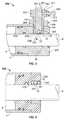
FIGURE 2 , an alternate embodiment of acylinder assembly 102 is shown. In this embodiment, thecylinder body 4 and thecylinder rod 6 are essentially the same as inFIGURE 1 . A detailed description of these members will not be repeated, but the numbers will be carried forward for similar items. - A
gland member 120 is positioned at the end of thecylinder body 4. As shown inFIGURE 2 , a portion ofgland member 120 is positioned within thecylinder chamber 8.Outer groove 21,inner groove 123 and mountingring 25 cooperate to maintaingland member 120 in position relative to thecylinder body 4. Aperipheral flange 124 extends outward from thegland member 120. A leadingsurface 126 of theflange 124 engages or is in close proximity to theend surface 14 of thecylinder body 4 when thegland member 120 is fully inserted in thecylinder body 4. A circumferentially extendingmating projection recess 131 is provided on amating surface 133 of thegland member 120. On many existinggland members 120, therecess 131 is made by simply removing the previously installed wiper seal and using the seal groove as therecess 131. - A
sensor mounting device 135 is configured to be attached to themating surface 133 of thegland member 120. Thesensor mounting device 135 has acircular mating projection 137 that is positioned inmating projection recess 131 when thesensor mounting device 135 is properly mounted to thegland member 120. The cooperation of themating projection 137 and themating projection recess 131 helps to ensure that thesensor mounting device 135 will be properly mounted to and properly seated in thegland member 120. A mountingscrew 139 extends through anopening 141 formed in thesensor mounting device 135 to a threadedopening 143 of thegland member 120 to secure thesensor mounting device 135 to thegland member 120. - A
seal groove 128 may be provided along the outer surface of thegland member 120. Aseal 130 is provided in theseal groove 128. Theseal 130 is resiliently deformed against thechamber wall 10 to provide a sealing engagement between thegland member 120 and thechamber wall 10 of thecylinder body 4. - A
rod opening 132 extends through thegland member 120. Therod opening 132 extends along the longitudinal axis of thegland member 120 and is configured to receive thecylinder rod 6 therein. Therod opening 132 is dimensioned to allow thecylinder rod 6 to slide therethrough. Acomplimentary rod opening 145 extends through thesensor mounting device 135. Therod opening 145 extends along the longitudinal axis of thesensor mounting device 135 and is configured to receive thecylinder rod 6 therein. Therod opening 145 is dimensioned to allow thecylinder rod 6 to slide therethrough. Aseal groove 134 may be provided in thegland member 120 along aninner wall 136 that defines therod opening 132. Arod seal 138 is provided in theseal groove 134. Therod seal 138 is resiliently deformed against thecylinder rod 6 to provide a sealing engagement between thegland member 120 and thecylinder rod 6. Anotherseal groove 140 may be provided along theinner wall 147 of thesensor mounting device 135. Awiper seal 142 is provided in theseal groove 140. Thewiper seal 142 is resiliently deformed against thecylinder rod 6 to provide a sealing engagement between thesensor mounting device 135 and thecylinder rod 6. Theseals cylinder rod 6 to keep the area of the cylinder rod between theseals - An
opening 144 is provided in thesensor mounting device 135. Theopening 144 extends from anouter wall 146 of thesensor mounting device 135 to theinner wall 147. Theopening 144 has a generally cylindrical configuration and extends from therod opening 145 in a radial direction relative to therod opening 145. An internal portion ofopening 144 has a threadedarea 148. However, in an alternative embodiment, opening 144 can define a non-cylindrical profile and may extend in a non-radial direction relative to therod opening 145. - A
sensor housing bolt 50 is provided inopening 144. Thebolt 50 has ahead 52 andneck portion 54. Theneck portion 54 extends from thehead 52 to anend surface 56. Provided on theneck portion 54 proximate theend surface 56 are finely spacedthreads 58. Asensor 60 is mounted through theend surface 56 of theneck portion 54. As previously described with respect to the first embodiment, thesensor 60 is mounted to acircuit board 70. In the embodiment shown, thesensor 60 is reflow soldered to thecircuit board 70, but other methods of mounting can be used. On the opposed face of thecircuit board 70, amagnet 72 is mounted thereon, by glue or other means. Themagnet 72,circuit board 70 andsensor 60 assembly is glued or otherwise mounted in anopening 74 provided in the bottom of thebolt 50. In this position, afree end 62 of thesensor 60 extends beyond theend surface 56 ofbolt 50. Ahex nut 64 is positioned around the circumference of theneck portion 54 ofbolt 50 proximate thesensor mounting device 135. Thehex nut 64 cooperates with thesensor mounting device 135 andbolt 50 to maintain thebolt 50 in the desired position relative to thesensor mounting device 135. - Positioning the
sensor 60 at theend surface 56 ofbolt 50 allows the sensor to be positioned proximate thecylinder rod 6. In addition, as thebolt 50 has finely spacedthreads 58 which cooperate with the finely spaced threads of threadedarea 148 ofopening 144, the positioning of thesensor 60 relative to thecylinder rod 6 can be incrementally adjusted to optimize the gap provided between thesensor 60 andcylinder rod 6. - Referring to
FIGURE 3 , another alternate embodiment of acylinder assembly 202 is shown. In this embodiment, thecylinder body 4, thecylinder rod 6 and thegland member 20 are essentially the same as inFIGURE 1 . A detailed description of these members will not be repeated, but the numbers will be carried forward for similar items. - An
opening 244 is provided in thegland member 20. Theopening 244 extends from anouter wall 246 of thegland member 20 to theinner wall 236. Theopening 244 has a generally cylindrical configuration and extends from therod opening 32 in a radial direction relative to therod opening 32. An internal portion ofopening 244 has a threadedarea 248. However, in an alternative embodiment, opening 244 can define a non-cylindrical profile and may extend in a non-radial direction relative to therod opening 32. - A
sensor housing bolt 250 is provided inopening 244. Thebolt 250 has ahead 252 andneck portion 254. Theneck portion 254 extends from thehead 252 to anend surface 256. Provided on theneck portion 254 proximate theend surface 256 are finely spacedthreads 258. Asensor 60 is mounted through theend surface 267 of thesensor rod assembly 261. As best shown inFIGURE 3 , asensor rod assembly 261 extends through alongitudinally extending opening 263 formed inbolt 250. Thesensor 60 is retained in acavity 265 provided at anend surface 267 of thesensor rod assembly 261. Theend surface 267 of thesensor rod assembly 261 is provided in alignment with theend surface 256 of thebolt 250. As previously described, thesensor 60 is mounted to acircuit board 70. On the opposed face of thecircuit board 70, amagnet 72 is mounted thereon. Themagnet 72,circuit board 70 andsensor 60 assembly is mounted in thecavity 265 provided in thesensor rod assembly 261. In this position, afree end 62 of thesensor 60 extends beyond theend surface 267 of thesensor rod assembly 261 and theend surface 256 ofbolt 250. Ahex nut 264 is positioned around the circumference of theneck portion 254 ofbolt 250 proximate thegland member 20. Thehex nut 264 cooperates with thegland member 20 andbolt 250 to maintain thebolt 250 in the desired position relative to thegland member 20. - An adjustment member or threaded
set screw 269 extends through a threaded opening 271 provided in thehead 252 ofbolt 250. The opening 271 and setscrew 269 extend in a direction that is essentially perpendicular to theopening 263. Ahex nut 273 cooperates with thehead 252 and theset screw 269 to maintain theset screw 269 in the desired position. Although only oneset screw 269 is shown, two or more set screws may be provided and spaced about the circumference of thehead 252. - Positioning the
sensor 60 at theend surface 256 of thebolt 250 allows the sensor to be positioned proximate thecylinder rod 6. In addition, as thebolt 250 has finely spacedthreads 258 which cooperate with the finely spacedthreads 248 ofopening 244, the positioning of thesensor 60 relative to thecylinder rod 6 can be incrementally adjusted to optimize the gap provided between thesensor 60 andcylinder rod 6. Adjusting the set screw or setscrews 269 may result in the adjustment of thesensor rod assembly 261 and thesensor 60 attached thereto, thereby helping to control the angular orientation and sensitivity direction of the sensor. - Referring to
FIGURE 4 , an embodiment similar to that ofFIGURE 3 is shown. In this embodiment, theset screw 269 andhex nut 273 have been eliminated. In order to provide thesensor 60 with the correct angular orientation, thesensor rod assembly 261 has been provided with finely spacedthreads 290 which cooperate with finely spacedthreads 292 provided around theopening 263.Threads threads sensor 60, thereby allowing thesensor 60 be independently placed in proper angular alignment and placed in proper position relative to thecylinder rod 6 to optimize the gap provided between thesensor 60 and thecylinder rod 6. - A
hex nut 294 is positioned about therod assembly 261 proximate thehead 252 of thesensor housing bolt 250. Thehex nut 294 cooperates with thehead 252 to maintain therod assembly 261 in proper position. Atool engagement area 296 on therod assembly 261 is provided proximate thehex nut 294. Thetool engagement area 296 allows an operator to properly position and maintain therod assembly 261 in position as thehex nut 294 is tightened. - Referring to
FIGURE5 , another alternate embodiment of acylinder assembly 302 is shown. In this embodiment, thecylinder body 4 and thecylinder rod 6 are the essentially the same as inFIGURE 1 . A detailed description of these members will not be repeated, but the numbers will be carried forward for similar items. - A generally
cylindrical gland member 320 is positioned at the end of thecylinder body 4. As shown inFIGURE5 , a portion ofgland member 320 is positioned within thecylinder chamber 8. As thegland member 320 has many of the same features as thegland member 220, this description will focus on the differences betweengland member 320 andgland member 220. - A
seal groove 340 may be provided along theinner wall 336 of thegland member 320. Awiper seal 342 is provided in theseal groove 340. Thewiper seal 342 is resiliently deformed against thecylinder rod 6 to provide a sealing engagement between thegland member 320 and thecylinder rod 6. Asensor 60 is provided in thewiper seal 342. In this embodiment, the manufacturing tolerances of theseal groove 340,wiper seal 342 andsensor 60 must be properly controlled to ensure that thesensor 60 is properly positioned relative to thecylinder rod 6. - The
cylinder rod 6 has a coating in which discrete signals can be positioned or embedded. The discrete signals can include binary data, data containing 'hi-lo' or '0-1' information, or such other data. The signals can be recorded in a magnetically hard layer on thecylinder rod 6 or in any other known manner. Alternatively, the discrete signals can be provided on thecylinder rod 6 in any number of ways that allow the signals to be detectable by thesensor 60. Referring toFIGS. 6 and7, three data tracks are recorded or embedded on thecylinder rod 6. The three tracks arefirst timing data 490,second timing data 491, andposition data 492. - As shown in
FIGS. 6 and7,first timing data 490 andsecond timing data 491 are ninety degrees out of phase. However, the timing data my be out of phase an amount different than ninety degrees. As thesensor 60 reads the signals from thefirst timing data 490 and thesecond timing data 491, the sensor reads in which order they go 'hi-lo' or 'lo-hi' and when they are both 'lo' or 'hi'. By so doing, the direction of motion of thecylinder rod 6 can be determined. As an example, thefirst timing data 490 and thesecond timing data 491 shown inFIGURE 6 indicate thecylinder rod 6 is extending, while thefirst timing data 490 and thesecond timing data 491 shown inFIGURE 7 indicate thecylinder rod 6 is retracting. - The
position data 492 can be in the form of a binary number or a non-repeating, random sequence. Thesensors 60 can read the signals from thefirst timing data 490 and theposition data 492 to determine the absolute position of thecylinder rod 6. Using thefirst timing data 490 as a clock, the signals from theposition data 492 can be accurately read. When compared to information stored in memory, the readings can be used to determine the absolute position of thecylinder rod 6. Consequently, as the absolute position is determined, rather than a relative position, no reference point need be established. Theposition data 492 can include sequences denoting start-bit, end-bit, breakers between data, direction data, etc. - For
sensors 60 to properly read the signals fromfirst timing data 490,second timing data 491 andposition data 492, thesensors 60 must be aligned with the tracks on thecylinder rod 6 in which the information is embedded. Alternatively, if the information is embedded in a nonsymetric binary code (as shown inFIGS. 8 and 9 ) or the like around the entire circumference of thecylinder rod 6, thesensor 60 must not be accurately positioned. In this circumstance, thesensor 60 could be free to move or rotate about thecylinder rod 6. As an example, the nonsymetric binary code shown inFIGURE 8 indicates thecylinder rod 6 is extending, while the nonsymetric binary code shown inFIGURE 9 indicates thecylinder rod 6 is retracting. - In the first alternative, in which the
sensor 60 must be aligned, the gland must be maintained in position relative to the cylinder body. Many ways are conceived to accurately align and maintain the gland, and ultimately the sensor, in position. A set screw could extend through thecylinder body 4 and engage a set screw receiving area of the gland to ensure proper position. Alternatively, a keying projection could extend from thecylinder body 4. The keying projection would cooperate with a keying recess of the gland to allow the gland to be inserted into the cylinder body in only one position. Other known methods could also be used. With thesensor 60 accurately positioned and maintained, thecylinder rod 6 must be properly and accurately inserted so that the tracks with thedata sensor 60. In the embodiment shown inFIGURE 3 , thecylinder rod 6 andsensor 60 may be slightly misaligned, as thesensor rod assembly 261 can be adjusted to control the angular orientation and sensitivity of thesensor 60. - In the second alternative, where the data is embedded about the entire circumference of the
cylinder rod 6, the gland may rotate or move relative to thecylinder rod 6, without affecting the operation of the sensor. As thedata cylinder rod 6, the initial position or the continuing position of thesensor 60 relative to a particular track of thecylinder rod 6 is not critical. - While the invention has been described with reference to a preferred embodiment, it will be understood by those skilled in the art that various changes may be made and equivalents may be substituted for elements thereof without departing from the scope of the invention. In addition, many modifications may be made to adapt a particular situation or material to the teachings of the invention without departing from the essential scope thereof. Therefore, it is intended that the invention not be limited to the particular embodiment disclosed as the best mode contemplated for carrying out this invention, but that the invention will include all embodiments falling within the scope of the appended claims.
Claims (12)
- A cylinder assembly (2) comprising:- a cylinder body (4) having a cylinder chamber (8) extending therein;- a gland member (20) having a rod opening (32) extending therethrough, said gland member (20) positioned at an end of said cylinder body (4), a portion of said gland member (20) is mounted in said cylinder chamber (8);- a cylinder rod (6) movably arranged in said cylinder chamber (8) and said rod opening (32), said cylinder rod (6) having detectable features disposed along a length of said cylinder rod (6);- a sensor (60) mounted on said gland member (20); said sensor (60) being operable to read the one or more detectable features of said cylinder rod (6) to detect the motion and the absolute position of said cylinder rod (6);- a sensor receiving opening (244) is provided in said gland member (20), said sensor receiving opening (244) extends from a rod opening (32) in a radial direction to an outer wall of said gland member (20),- a sensor housing mechanism (250) being provided in said sensor receiving opening (244),- a sensor rod assembly (261) being provided in a longitudinal opening provided in said sensor housing mechanism (250), said adjustable sensor (60) being mounted through an end surface of said sensor rod assembly (261), such that a free end of said adjustable sensor (60) extends beyond the end surface of said sensor rod assembly (266) and said sensor housing mechanism (250), said sensor rod assembly (261) and said longitudinal opening having threads (290, 292) which cooperate with each other to allow for further adjustment of said sensor (60) to properly space said sensor (60) from said cylinder rod (6) and to properly align said sensor (60),characterized by said sensor housing mechanism (250) and said longitudinal receiving opening (244) having threads (248, 258) which cooperate with each other to allow for the adjustment of said sensor (60) to properly space said sensor (60) from said cylinder rod (6) and to properly align said sensor (60).
- The cylinder assembly (2) of claim 1 wherein a first portion of said gland member (20) is mounted in said cylinder chamber (8) and a second portion of said gland member (20) extends beyond said cylinder chamber (8) and said sensor (60) can be incrementally adjusted relative to said cylinder rod (6) to optimize the gap provided between the sensor (60) and the cylinder rod (6).
- The cylinder assembly (2) of claim 1 or 2 wherein said sensor receiving opening (244) and said sensor housing mechanism (250) have finely spaced threads (248, 258) which cooperate to maintain said sensor housing mechanism (250) in said sensor receiving opening (244) and which allow said sensor housing mechanism (250) to be incrementally adjusted, thereby allowing the adjustment of the adjustable sensor (60) relative to said cylinder rod (6).
- The cylinder assembly (2) of claim 3 wherein the threads (290, 292) of said sensor rod assembly (261) and said longitudinal opening have a different thread pitch than the finely spaced threads (248, 258) of said sensor receiving opening (244) and said sensor housing mechanism (250).
- The cylinder assembly of claim 1 and any claim dependent thereon wherein a locking member (264) engages said sensor housing mechanism (250) proximate the outer wall of said gland member (20), said locking member (264) cooperating with said sensor housing mechanism (250) and said gland member (20) to maintain said sensor housing mechanism (250) in position relative to said gland member (20).
- The cylinder assembly of claim 1 wherein a sensor receiving opening (144) is provided in a sensor mounting device (135) that is mounted to said gland member (120), said sensor receiving opening (144) extends from rod opening (145) in said sensor mounting device (135) in a radial direction to an outer wall of the sensor mounting device (135).
- The cylinder assembly of claim 6 wherein a mounting screw (139) extends through said sensor mounting device (135) into said gland member (120) to secure said sensor mounting device (135) to said gland member (120).
- The cylinder assembly of claim 1 wherein said detectable features are embedded in a magnetically hard layer on said cylinder rod (6).
- The cylinder assembly according to any of the preceding claims wherein said detectable features are at least three tracks of data provided on said cylinder rod (6).
- The cylinder assembly of claim 9 wherein a first track includes first timing data (490) and a second track includes second timing data (491), said first timing data (490) and second timing data (491) being positioned out of phase, thereby allowing said sensor (60) to detect the motion of said cylinder rod (6).
- The cylinder assembly of claim 10 wherein a third track includes position data (492), said first timing data (490) and said position data (492) allow said sensor (60) to determine the absolute position of said cylinder rod (6).
- The cylinder assembly according to any of the preceding claims wherein the detectable features are in the form of binary numbers or in the form of a non-repeating sequence.
Applications Claiming Priority (1)
| Application Number | Priority Date | Filing Date | Title |
|---|---|---|---|
| US12/262,582US8240240B2 (en) | 2008-10-31 | 2008-10-31 | Cylinder position sensor |
Publications (2)
| Publication Number | Publication Date |
|---|---|
| EP2182222A1 EP2182222A1 (en) | 2010-05-05 |
| EP2182222B1true EP2182222B1 (en) | 2016-06-29 |
Family
ID=41589555
Family Applications (1)
| Application Number | Title | Priority Date | Filing Date |
|---|---|---|---|
| EP09174725.3AActiveEP2182222B1 (en) | 2008-10-31 | 2009-11-02 | Adjustable cylinder position sensor |
Country Status (2)
| Country | Link |
|---|---|
| US (1) | US8240240B2 (en) |
| EP (1) | EP2182222B1 (en) |
Families Citing this family (11)
| Publication number | Priority date | Publication date | Assignee | Title |
|---|---|---|---|---|
| US8967035B2 (en)* | 2012-05-24 | 2015-03-03 | Caterpillar Inc. | Sensor coupler for piston-cylinder assembly |
| DE202012009001U1 (en)* | 2012-09-19 | 2014-01-15 | Bümach Engineering International B.V. | working cylinder |
| US9470556B2 (en) | 2012-10-18 | 2016-10-18 | Cnh Industrial Canada, Ltd. | Method and apparatus for sensing position |
| CA2866050C (en) | 2013-12-11 | 2019-02-26 | Cnh Industrial Canada, Ltd. | Agricultural implement actuator sensor protection |
| WO2017023303A1 (en) | 2015-08-05 | 2017-02-09 | Stren Microlift Technology, Llc | Hydraulic pumping system for use with a subterranean well |
| WO2017123400A1 (en)* | 2016-01-11 | 2017-07-20 | Parker-Hannifin Corporation | Optical sensor mounting interface with integrated hydraulic vent |
| WO2017155788A1 (en)* | 2016-03-08 | 2017-09-14 | Weatherford Technology Holdings, Llc | Position sensing for wellsite pumping unit |
| US10251327B2 (en) | 2016-11-22 | 2019-04-09 | Cnh Industrial Canada, Ltd. | Agricultural implement hydraulic rephasing unit and method |
| CN107843228B (en)* | 2017-10-11 | 2019-09-17 | 广州市健坤网络科技发展有限公司 | The acquisition methods of Multi Slice Mode time sequence spacing track area |
| CN109854568A (en)* | 2018-12-19 | 2019-06-07 | 厦门金龙汽车车身有限公司 | A kind of fixed structure and fixing means of cylinder sensor |
| US11828306B2 (en) | 2021-04-30 | 2023-11-28 | Industries Mailhot Inc. | Method and a system for position measurement of a piston rod of a hydraulic cylinder |
Family Cites Families (24)
| Publication number | Priority date | Publication date | Assignee | Title |
|---|---|---|---|---|
| US3650182A (en)* | 1969-09-17 | 1972-03-21 | Cessna Aircraft Co | Closure for fluid pressure vessel |
| US3956973A (en)* | 1972-07-11 | 1976-05-18 | Basic Aluminum Castings Company | Die casting machine with piston positioning control |
| US4061026A (en) | 1976-05-07 | 1977-12-06 | United Technologies Corporation | Full throttle, specific speed tests in internal combustion engine diagnostics |
| US4316145A (en)* | 1976-10-01 | 1982-02-16 | Electro-Mechanical Products | Fluid pressure actuator with proximity position sensor |
| US4411577A (en) | 1980-03-07 | 1983-10-25 | Rapistan Division, Lear Siegler, Inc. | Vehicle sensor monitoring system |
| GB2095861B (en) | 1981-03-31 | 1985-01-03 | Toyoda Automatic Loom Works | Fork lift control system |
| JPS63122902A (en) | 1986-11-13 | 1988-05-26 | Ckd Controls Ltd | Apparatus for confirming position of moving body |
| DE8700227U1 (en) | 1987-01-07 | 1987-09-10 | Delmag-Maschinenfabrik Reinhold Dornfeld Gmbh + Co, 7300 Esslingen | Hydraulic bear |
| US4829418A (en) | 1987-04-24 | 1989-05-09 | Laser Alignment, Inc. | Apparatus and method for controlling a hydraulic excavator |
| WO1992008058A1 (en)* | 1990-10-26 | 1992-05-14 | Kabushiki Kaisha Komatsu Seisakusho | Device for mounting position detecting sensor |
| US5241278A (en) | 1991-07-05 | 1993-08-31 | Caterpillar Inc. | Radio frequency linear position sensor using two subsequent harmonics |
| US5182980A (en)* | 1992-02-05 | 1993-02-02 | Caterpillar Inc. | Hydraulic cylinder position sensor mounting apparatus |
| FI91325C (en)* | 1992-04-07 | 1994-06-10 | Partek Cargotec Oy | Position scale and optical read sensor to read this position scale |
| US5572809A (en) | 1995-03-30 | 1996-11-12 | Laser Alignment, Inc. | Control for hydraulically operated construction machine having multiple tandem articulated members |
| US6509733B2 (en) | 2000-12-20 | 2003-01-21 | Caterpillar Inc | Fluid cylinder with embedded positioning sensor |
| DE10119941A1 (en) | 2001-04-23 | 2002-10-24 | Mannesmann Rexroth Ag | Relative position measurement for piston rod in a pressure medium cylinder, uses random coding, e.g. Manchester coding, of the coding elements along the length of the piston rod |
| EP1461585B1 (en)* | 2002-01-04 | 2010-12-08 | Parker Hannifin Corporation | Cylinder with optical sensing device and method |
| US6690160B2 (en) | 2002-04-22 | 2004-02-10 | Deere & Company | Position sensing apparatus |
| JP2006525529A (en) | 2003-05-06 | 2006-11-09 | エスアールアイ インターナショナル | System and method for recording piston rod position information in a magnetic layer on a piston rod |
| US7162947B2 (en) | 2003-12-19 | 2007-01-16 | Caterpillar Inc | Mount for cylinder position sensor |
| US6941827B2 (en)* | 2003-12-19 | 2005-09-13 | Caterpillar Inc. | Mounting apparatus and method for cylinder position sensor |
| US7116097B2 (en) | 2004-10-27 | 2006-10-03 | Deere & Company | System and method for detecting the axial position of a shaft or a member attached thereto |
| US7178446B2 (en) | 2005-02-28 | 2007-02-20 | Caterpillar Inc | Cylinder rod with position sensor surface markings |
| US7215112B1 (en) | 2005-11-07 | 2007-05-08 | Delphi Technologies, Inc. | Non-contact linear absolute position sensor |
- 2008
- 2008-10-31USUS12/262,582patent/US8240240B2/enactiveActive
- 2009
- 2009-11-02EPEP09174725.3Apatent/EP2182222B1/enactiveActive
Also Published As
| Publication number | Publication date |
|---|---|
| US8240240B2 (en) | 2012-08-14 |
| EP2182222A1 (en) | 2010-05-05 |
| US20100107869A1 (en) | 2010-05-06 |
Similar Documents
| Publication | Publication Date | Title |
|---|---|---|
| EP2182222B1 (en) | Adjustable cylinder position sensor | |
| US6941827B2 (en) | Mounting apparatus and method for cylinder position sensor | |
| CN100480635C (en) | Rotary shaft, loopy encoder and method for manufacturing the rotary shaft | |
| EP1357365B1 (en) | Position detecting apparatus | |
| US7047865B2 (en) | Cylinder with fiber optical position sensing device | |
| US5922953A (en) | Sensor apparatus with self-adjusting mechanism for minimizing airgap | |
| US7788983B2 (en) | Sensor arrangement | |
| US20050274254A1 (en) | Hydraulic cylinder with position encoder | |
| US20180135960A1 (en) | Position sensor and actuator with position sensor | |
| US6940276B2 (en) | Sensor for power clamp arm | |
| EP2676038B1 (en) | Floating optical sensor mount | |
| EP1069321B1 (en) | Directional control valve having position detecting function | |
| EP1797399A2 (en) | Magnetic absolute position sensor featuring a variable length of the individual encoding segments | |
| EP2484949B1 (en) | Hydraulic valve device with associated spool displacement transducer | |
| US20080030188A1 (en) | Non-contact position sensor | |
| US20040164732A1 (en) | Rotary encoder | |
| EP0080466A1 (en) | Hydraulic linear actuator | |
| JPH04507066A (en) | hydraulic drive device | |
| US20200254643A1 (en) | Adjusting Device and Method for Adjusting a Gap Width of a Rotary Punch Device | |
| EP1544476B1 (en) | Mount for cylinder position sensor | |
| JP2008121786A (en) | Range detecting device | |
| JPH0329607Y2 (en) | ||
| WO2019176712A1 (en) | Hydraulic cylinder equipped with detection mechanism | |
| JP2546682B2 (en) | Injection speed sensor for die casting machine | |
| WO2011055338A1 (en) | Alignment device for run out measurement apparatus |
Legal Events
| Date | Code | Title | Description |
|---|---|---|---|
| PUAI | Public reference made under article 153(3) epc to a published international application that has entered the european phase | Free format text:ORIGINAL CODE: 0009012 | |
| AK | Designated contracting states | Kind code of ref document:A1 Designated state(s):AT BE BG CH CY CZ DE DK EE ES FI FR GB GR HR HU IE IS IT LI LT LU LV MC MK MT NL NO PL PT RO SE SI SK SM TR | |
| AX | Request for extension of the european patent | Extension state:AL BA RS | |
| 17P | Request for examination filed | Effective date:20101105 | |
| 17Q | First examination report despatched | Effective date:20101130 | |
| RAP1 | Party data changed (applicant data changed or rights of an application transferred) | Owner name:CNH ITALIA S.P.A. | |
| RAP1 | Party data changed (applicant data changed or rights of an application transferred) | Owner name:CNH ITALIA S.P.A. | |
| RAP1 | Party data changed (applicant data changed or rights of an application transferred) | Owner name:CNH INDUSTRIAL ITALIA S.P.A. | |
| GRAP | Despatch of communication of intention to grant a patent | Free format text:ORIGINAL CODE: EPIDOSNIGR1 | |
| INTG | Intention to grant announced | Effective date:20160121 | |
| GRAS | Grant fee paid | Free format text:ORIGINAL CODE: EPIDOSNIGR3 | |
| GRAA | (expected) grant | Free format text:ORIGINAL CODE: 0009210 | |
| AK | Designated contracting states | Kind code of ref document:B1 Designated state(s):AT BE BG CH CY CZ DE DK EE ES FI FR GB GR HR HU IE IS IT LI LT LU LV MC MK MT NL NO PL PT RO SE SI SK SM TR | |
| REG | Reference to a national code | Ref country code:GB Ref legal event code:FG4D | |
| REG | Reference to a national code | Ref country code:CH Ref legal event code:EP | |
| REG | Reference to a national code | Ref country code:DE Ref legal event code:R084 Ref document number:602009039426 Country of ref document:DE | |
| REG | Reference to a national code | Ref country code:AT Ref legal event code:REF Ref document number:809347 Country of ref document:AT Kind code of ref document:T Effective date:20160715 | |
| REG | Reference to a national code | Ref country code:IE Ref legal event code:FG4D | |
| REG | Reference to a national code | Ref country code:GB Ref legal event code:746 Effective date:20160708 | |
| REG | Reference to a national code | Ref country code:DE Ref legal event code:R096 Ref document number:602009039426 Country of ref document:DE | |
| REG | Reference to a national code | Ref country code:FR Ref legal event code:PLFP Year of fee payment:8 | |
| REG | Reference to a national code | Ref country code:LT Ref legal event code:MG4D | |
| PG25 | Lapsed in a contracting state [announced via postgrant information from national office to epo] | Ref country code:NO Free format text:LAPSE BECAUSE OF FAILURE TO SUBMIT A TRANSLATION OF THE DESCRIPTION OR TO PAY THE FEE WITHIN THE PRESCRIBED TIME-LIMIT Effective date:20160929 Ref country code:FI Free format text:LAPSE BECAUSE OF FAILURE TO SUBMIT A TRANSLATION OF THE DESCRIPTION OR TO PAY THE FEE WITHIN THE PRESCRIBED TIME-LIMIT Effective date:20160629 Ref country code:LT Free format text:LAPSE BECAUSE OF FAILURE TO SUBMIT A TRANSLATION OF THE DESCRIPTION OR TO PAY THE FEE WITHIN THE PRESCRIBED TIME-LIMIT Effective date:20160629 | |
| REG | Reference to a national code | Ref country code:NL Ref legal event code:MP Effective date:20160629 | |
| PG25 | Lapsed in a contracting state [announced via postgrant information from national office to epo] | Ref country code:GR Free format text:LAPSE BECAUSE OF FAILURE TO SUBMIT A TRANSLATION OF THE DESCRIPTION OR TO PAY THE FEE WITHIN THE PRESCRIBED TIME-LIMIT Effective date:20160930 Ref country code:NL Free format text:LAPSE BECAUSE OF FAILURE TO SUBMIT A TRANSLATION OF THE DESCRIPTION OR TO PAY THE FEE WITHIN THE PRESCRIBED TIME-LIMIT Effective date:20160629 Ref country code:LV Free format text:LAPSE BECAUSE OF FAILURE TO SUBMIT A TRANSLATION OF THE DESCRIPTION OR TO PAY THE FEE WITHIN THE PRESCRIBED TIME-LIMIT Effective date:20160629 Ref country code:HR Free format text:LAPSE BECAUSE OF FAILURE TO SUBMIT A TRANSLATION OF THE DESCRIPTION OR TO PAY THE FEE WITHIN THE PRESCRIBED TIME-LIMIT Effective date:20160629 Ref country code:SE Free format text:LAPSE BECAUSE OF FAILURE TO SUBMIT A TRANSLATION OF THE DESCRIPTION OR TO PAY THE FEE WITHIN THE PRESCRIBED TIME-LIMIT Effective date:20160629 | |
| REG | Reference to a national code | Ref country code:AT Ref legal event code:MK05 Ref document number:809347 Country of ref document:AT Kind code of ref document:T Effective date:20160629 | |
| PG25 | Lapsed in a contracting state [announced via postgrant information from national office to epo] | Ref country code:CZ Free format text:LAPSE BECAUSE OF FAILURE TO SUBMIT A TRANSLATION OF THE DESCRIPTION OR TO PAY THE FEE WITHIN THE PRESCRIBED TIME-LIMIT Effective date:20160629 Ref country code:SK Free format text:LAPSE BECAUSE OF FAILURE TO SUBMIT A TRANSLATION OF THE DESCRIPTION OR TO PAY THE FEE WITHIN THE PRESCRIBED TIME-LIMIT Effective date:20160629 Ref country code:RO Free format text:LAPSE BECAUSE OF FAILURE TO SUBMIT A TRANSLATION OF THE DESCRIPTION OR TO PAY THE FEE WITHIN THE PRESCRIBED TIME-LIMIT Effective date:20160629 Ref country code:EE Free format text:LAPSE BECAUSE OF FAILURE TO SUBMIT A TRANSLATION OF THE DESCRIPTION OR TO PAY THE FEE WITHIN THE PRESCRIBED TIME-LIMIT Effective date:20160629 Ref country code:IS Free format text:LAPSE BECAUSE OF FAILURE TO SUBMIT A TRANSLATION OF THE DESCRIPTION OR TO PAY THE FEE WITHIN THE PRESCRIBED TIME-LIMIT Effective date:20161029 | |
| PG25 | Lapsed in a contracting state [announced via postgrant information from national office to epo] | Ref country code:PL Free format text:LAPSE BECAUSE OF FAILURE TO SUBMIT A TRANSLATION OF THE DESCRIPTION OR TO PAY THE FEE WITHIN THE PRESCRIBED TIME-LIMIT Effective date:20160629 Ref country code:AT Free format text:LAPSE BECAUSE OF FAILURE TO SUBMIT A TRANSLATION OF THE DESCRIPTION OR TO PAY THE FEE WITHIN THE PRESCRIBED TIME-LIMIT Effective date:20160629 Ref country code:PT Free format text:LAPSE BECAUSE OF FAILURE TO SUBMIT A TRANSLATION OF THE DESCRIPTION OR TO PAY THE FEE WITHIN THE PRESCRIBED TIME-LIMIT Effective date:20161031 Ref country code:BE Free format text:LAPSE BECAUSE OF FAILURE TO SUBMIT A TRANSLATION OF THE DESCRIPTION OR TO PAY THE FEE WITHIN THE PRESCRIBED TIME-LIMIT Effective date:20160629 Ref country code:SM Free format text:LAPSE BECAUSE OF FAILURE TO SUBMIT A TRANSLATION OF THE DESCRIPTION OR TO PAY THE FEE WITHIN THE PRESCRIBED TIME-LIMIT Effective date:20160629 Ref country code:ES Free format text:LAPSE BECAUSE OF FAILURE TO SUBMIT A TRANSLATION OF THE DESCRIPTION OR TO PAY THE FEE WITHIN THE PRESCRIBED TIME-LIMIT Effective date:20160629 | |
| REG | Reference to a national code | Ref country code:DE Ref legal event code:R097 Ref document number:602009039426 Country of ref document:DE | |
| PLBE | No opposition filed within time limit | Free format text:ORIGINAL CODE: 0009261 | |
| STAA | Information on the status of an ep patent application or granted ep patent | Free format text:STATUS: NO OPPOSITION FILED WITHIN TIME LIMIT | |
| PG25 | Lapsed in a contracting state [announced via postgrant information from national office to epo] | Ref country code:DK Free format text:LAPSE BECAUSE OF FAILURE TO SUBMIT A TRANSLATION OF THE DESCRIPTION OR TO PAY THE FEE WITHIN THE PRESCRIBED TIME-LIMIT Effective date:20160629 | |
| 26N | No opposition filed | Effective date:20170330 | |
| REG | Reference to a national code | Ref country code:CH Ref legal event code:PL | |
| PG25 | Lapsed in a contracting state [announced via postgrant information from national office to epo] | Ref country code:LI Free format text:LAPSE BECAUSE OF NON-PAYMENT OF DUE FEES Effective date:20161130 Ref country code:CH Free format text:LAPSE BECAUSE OF NON-PAYMENT OF DUE FEES Effective date:20161130 | |
| REG | Reference to a national code | Ref country code:IE Ref legal event code:MM4A | |
| PG25 | Lapsed in a contracting state [announced via postgrant information from national office to epo] | Ref country code:BG Free format text:LAPSE BECAUSE OF FAILURE TO SUBMIT A TRANSLATION OF THE DESCRIPTION OR TO PAY THE FEE WITHIN THE PRESCRIBED TIME-LIMIT Effective date:20160929 Ref country code:SI Free format text:LAPSE BECAUSE OF FAILURE TO SUBMIT A TRANSLATION OF THE DESCRIPTION OR TO PAY THE FEE WITHIN THE PRESCRIBED TIME-LIMIT Effective date:20160629 | |
| PG25 | Lapsed in a contracting state [announced via postgrant information from national office to epo] | Ref country code:LU Free format text:LAPSE BECAUSE OF NON-PAYMENT OF DUE FEES Effective date:20161130 | |
| REG | Reference to a national code | Ref country code:FR Ref legal event code:PLFP Year of fee payment:9 | |
| PG25 | Lapsed in a contracting state [announced via postgrant information from national office to epo] | Ref country code:IE Free format text:LAPSE BECAUSE OF NON-PAYMENT OF DUE FEES Effective date:20161102 | |
| PG25 | Lapsed in a contracting state [announced via postgrant information from national office to epo] | Ref country code:HU Free format text:LAPSE BECAUSE OF FAILURE TO SUBMIT A TRANSLATION OF THE DESCRIPTION OR TO PAY THE FEE WITHIN THE PRESCRIBED TIME-LIMIT; INVALID AB INITIO Effective date:20091102 Ref country code:CY Free format text:LAPSE BECAUSE OF FAILURE TO SUBMIT A TRANSLATION OF THE DESCRIPTION OR TO PAY THE FEE WITHIN THE PRESCRIBED TIME-LIMIT Effective date:20160629 | |
| PG25 | Lapsed in a contracting state [announced via postgrant information from national office to epo] | Ref country code:TR Free format text:LAPSE BECAUSE OF FAILURE TO SUBMIT A TRANSLATION OF THE DESCRIPTION OR TO PAY THE FEE WITHIN THE PRESCRIBED TIME-LIMIT Effective date:20160629 Ref country code:MC Free format text:LAPSE BECAUSE OF FAILURE TO SUBMIT A TRANSLATION OF THE DESCRIPTION OR TO PAY THE FEE WITHIN THE PRESCRIBED TIME-LIMIT Effective date:20160629 Ref country code:MK Free format text:LAPSE BECAUSE OF FAILURE TO SUBMIT A TRANSLATION OF THE DESCRIPTION OR TO PAY THE FEE WITHIN THE PRESCRIBED TIME-LIMIT Effective date:20160629 | |
| PG25 | Lapsed in a contracting state [announced via postgrant information from national office to epo] | Ref country code:MT Free format text:LAPSE BECAUSE OF NON-PAYMENT OF DUE FEES Effective date:20161102 | |
| REG | Reference to a national code | Ref country code:FR Ref legal event code:PLFP Year of fee payment:10 | |
| PGFP | Annual fee paid to national office [announced via postgrant information from national office to epo] | Ref country code:DE Payment date:20191128 Year of fee payment:11 | |
| PGFP | Annual fee paid to national office [announced via postgrant information from national office to epo] | Ref country code:GB Payment date:20191122 Year of fee payment:11 | |
| REG | Reference to a national code | Ref country code:DE Ref legal event code:R082 Ref document number:602009039426 Country of ref document:DE Representative=s name:MEISSNER BOLTE PATENTANWAELTE RECHTSANWAELTE P, DE | |
| REG | Reference to a national code | Ref country code:DE Ref legal event code:R119 Ref document number:602009039426 Country of ref document:DE | |
| GBPC | Gb: european patent ceased through non-payment of renewal fee | Effective date:20201102 | |
| PG25 | Lapsed in a contracting state [announced via postgrant information from national office to epo] | Ref country code:DE Free format text:LAPSE BECAUSE OF NON-PAYMENT OF DUE FEES Effective date:20210601 Ref country code:GB Free format text:LAPSE BECAUSE OF NON-PAYMENT OF DUE FEES Effective date:20201102 | |
| PGFP | Annual fee paid to national office [announced via postgrant information from national office to epo] | Ref country code:FR Payment date:20241126 Year of fee payment:16 | |
| PGFP | Annual fee paid to national office [announced via postgrant information from national office to epo] | Ref country code:IT Payment date:20241125 Year of fee payment:16 |