EP2181656A1 - Device for inserting medical implants - Google Patents
Device for inserting medical implantsDownload PDFInfo
- Publication number
- EP2181656A1 EP2181656A1EP09174333AEP09174333AEP2181656A1EP 2181656 A1EP2181656 A1EP 2181656A1EP 09174333 AEP09174333 AEP 09174333AEP 09174333 AEP09174333 AEP 09174333AEP 2181656 A1EP2181656 A1EP 2181656A1
- Authority
- EP
- European Patent Office
- Prior art keywords
- guide
- distal end
- proximal end
- hollow body
- medical implant
- Prior art date
- Legal status (The legal status is an assumption and is not a legal conclusion. Google has not performed a legal analysis and makes no representation as to the accuracy of the status listed.)
- Withdrawn
Links
- 239000007943implantSubstances0.000titleclaimsabstractdescription45
- 238000007789sealingMethods0.000claimsdescription10
- 238000006073displacement reactionMethods0.000claimsdescription5
- 239000004020conductorSubstances0.000claimsdescription4
- 230000014759maintenance of locationEffects0.000claimsdescription3
- 230000002441reversible effectEffects0.000claimsdescription2
- 210000001519tissueAnatomy0.000description14
- 238000002513implantationMethods0.000description5
- 238000003780insertionMethods0.000description5
- 230000037431insertionEffects0.000description5
- 238000005452bendingMethods0.000description3
- 239000003814drugSubstances0.000description3
- 210000003516pericardiumAnatomy0.000description3
- 210000004556brainAnatomy0.000description2
- 210000000038chestAnatomy0.000description2
- 210000004165myocardiumAnatomy0.000description2
- 230000035515penetrationEffects0.000description2
- 210000000779thoracic wallAnatomy0.000description2
- 230000005540biological transmissionEffects0.000description1
- 239000008280bloodSubstances0.000description1
- 210000004369bloodAnatomy0.000description1
- 210000004375bundle of hisAnatomy0.000description1
- 210000005242cardiac chamberAnatomy0.000description1
- 239000002131composite materialSubstances0.000description1
- 210000004351coronary vesselAnatomy0.000description1
- 230000006378damageEffects0.000description1
- 229940079593drugDrugs0.000description1
- 210000005003heart tissueAnatomy0.000description1
- 239000011796hollow space materialSubstances0.000description1
- 238000004519manufacturing processMethods0.000description1
- 239000000463materialSubstances0.000description1
- 238000000034methodMethods0.000description1
- 210000005036nerveAnatomy0.000description1
- 210000000653nervous systemAnatomy0.000description1
- 230000001225therapeutic effectEffects0.000description1
Images


Classifications
- A—HUMAN NECESSITIES
- A61—MEDICAL OR VETERINARY SCIENCE; HYGIENE
- A61N—ELECTROTHERAPY; MAGNETOTHERAPY; RADIATION THERAPY; ULTRASOUND THERAPY
- A61N1/00—Electrotherapy; Circuits therefor
- A61N1/02—Details
- A61N1/04—Electrodes
- A61N1/05—Electrodes for implantation or insertion into the body, e.g. heart electrode
- A61N1/0587—Epicardial electrode systems; Endocardial electrodes piercing the pericardium
- A—HUMAN NECESSITIES
- A61—MEDICAL OR VETERINARY SCIENCE; HYGIENE
- A61B—DIAGNOSIS; SURGERY; IDENTIFICATION
- A61B17/00—Surgical instruments, devices or methods
- A61B17/34—Trocars; Puncturing needles
- A61B17/3468—Trocars; Puncturing needles for implanting or removing devices, e.g. prostheses, implants, seeds, wires
- A—HUMAN NECESSITIES
- A61—MEDICAL OR VETERINARY SCIENCE; HYGIENE
- A61B—DIAGNOSIS; SURGERY; IDENTIFICATION
- A61B17/00—Surgical instruments, devices or methods
- A61B17/00234—Surgical instruments, devices or methods for minimally invasive surgery
- A61B2017/00238—Type of minimally invasive operation
- A61B2017/00243—Type of minimally invasive operation cardiac
- A—HUMAN NECESSITIES
- A61—MEDICAL OR VETERINARY SCIENCE; HYGIENE
- A61B—DIAGNOSIS; SURGERY; IDENTIFICATION
- A61B17/00—Surgical instruments, devices or methods
- A61B17/34—Trocars; Puncturing needles
- A61B2017/348—Means for supporting the trocar against the body or retaining the trocar inside the body
- A61B2017/3482—Means for supporting the trocar against the body or retaining the trocar inside the body inside
- A61B2017/3484—Anchoring means, e.g. spreading-out umbrella-like structure
- A61B2017/3488—Fixation to inner organ or inner body tissue
Definitions
- the inventionrelates to a device for the targeted permanent or temporary introduction of medical implants into a living being, which comprises an elongate body having a distal end and a proximal end, wherein the device is designed to be guided via an access into the living being that the proximal end remains outside the living being.
- the inventionrelates to a medical implant for permanent or temporary retention in a living being, which comprises a hollow body with a distal and a proximal end and with a continuous cavity along the longitudinal axis of the hollow body, wherein the hollow body is such that it is the device according to the invention and reversibly, and further includes an opening at each proximal and distal end through which the device can penetrate.
- Such known devicesare used to transfer electrode leads to a desired site of implantation into a subject, where they are then attached.
- a so-called guide wireis first placed through the venous system in a heart chamber or a coronary vessel, along which then an electrode line is introduced and fixed on the body tissue such as the heart wall. It becomes problematic when specific areas are to be specifically stimulated. This is the case, for example, when the physician wishes to fix electrode lines in a high-septum near the HIS bundle. There arises the problem that the electrode line must be brought to the place of fixation usually with a guide catheter. Due to the limited space, it is difficult to guide the electrode line through small bending radii of the guide catheter in the target area.
- the doctorcan no longer adequately press the electrode lead to the heart wall because it is in a 90 ° position to the insertion axis and the catheter does not provide enough support. Therefore, it is very difficult or often impossible to fix standard electrodes such as actively fixable screw electrodes in areas of the heart where the electrodes strike the heart tissue only tangentially or at a shallow angle.
- a catheterthat offers sufficiently large bending radii, but can lead the electrodes only at a shallow angle in the target area, which also prevents screwing due to the lack of pressure.
- an electrode lineto the epicard from the outside using a similar method.
- a guide catheteris inserted through the chest wall, in which then an electrode lead with fixation and attached to the outer heart wall (epicardium) is attached.
- the electrode leadcan not be inserted there at right angles, but it must be attempted to bring the electrode tangentially to the heart wall and then secure it.
- a commercially available Einschraubelektrodenein can then no longer be attached.
- the first aspect of the objectis achieved by a device for the targeted permanent or temporary introduction of medical implants into a living being, which comprises an elongated body with a distal end and a proximal end.
- the deviceis designed so that it can be guided via an access into the living being, so that the proximal end remains outside the living being and that the distal end has a fixing device with which the device can be releasably connected to the body tissue.
- the fixing deviceis designed to penetrate into the body tissue, thus preferably sharpened and particularly preferably acicular.
- the distal region of the deviceis temporarily fixed to the myocardium by the fixation device has penetrated into the body tissue.
- a medical implantcan be selectively fixed in the tissue.
- the implant for permanent or temporary whereabouts in a living beingcomprises a hollow body which is hollow throughout along a longitudinal axis with a distal and a proximal end, wherein the hollow body is adapted to receive the device according to the invention and to guide it reversibly, and in each case to an opening on the proximal and at the distal end, through which the device can penetrate, the opening at the distal end having a reversibly pierceable by the fixing device of the device sealing unit for sealing the hollow body continuously hollow.
- the fixing devicehas a pre-bend extending in the lateral direction, which preferably has a radius of 5 mm to 20 mm and / or a circular arc with an angle of 70 ° to 90 ° in the angular dimension.
- the implantcan be brought to the implantation site via the device, for example, guided between the thorax and the pericardium in a narrow space, then guided tangentially to the epicardium in a particularly narrow space in the pericardium and then fastened onto the myocardium at an appropriate angle. This allows the necessary penetration forces to be applied to the implant without being able to avoid it.
- the devicehas conventional properties, such as that the body and the fixing device are elastic, preferably made of a wire, more preferably of a wire with a diameter of less than or equal to 0, 36 mm.
- the devicepreferably has a locking device on the proximal end, which enables a releasable locking means directly or indirectly with the medical implant. As a result, the position between the device and the medical implant is adjusted or a displacement between the device and the implant is prevented.
- the devicefurther comprises a guide for reversibly guiding or holding the device, which has an elongate hollow body with a distal and a proximal end with a continuous cavity along a longitudinal axis, wherein the hollow body is such that it forms the device can record and reversibly lead and / or support.
- the guidecomprises in each case an opening at the proximal and at the distal end, which are connected to the hollow space of the hollow body and through which the device can penetrate, and a locking unit at the proximal end which enables a releasable locking directly or indirectly with the device, to adjust the position between the device and the guide or to prevent a shift between the device and the guide.
- the guideis formed as a sleeve, preferably as an elastic bendable Mandrinhülse.
- the insertion of an implantcan be further improved, since then the device is supported and much more stable.
- the insertion and placement of the electrode linecan be significantly simplified by the additional guide.
- a medical implant for permanent or temporary retention in a living beingwhich disengages a hollow body having a distal and a proximal end and a continuous cavity along a longitudinal axis.
- the hollow bodyis designed such that it can receive the device for the purposeful permanent or temporary introduction of medical implants into a living being and reversible.
- Each cavityhas an opening connected thereto at the proximal and distal ends through which the device can pass.
- the opening at the distal endhas a sealing unit which can be reversibly pierced by the fixing device of the device for the purposeful permanent or temporary introduction of medical implants into a living being for sealing the hollow body.
- the implantpreferably has an in his hollow body immediately proximal of the sealing unit located stop device with a bore and an abutment which is designed so that the fixing device of the device can penetrate the bore and the guide strikes the abutment.
- Thismakes it possible to guide the implant with the guide or with the stylet sleeve, which in a Force impact along the longitudinal axis in the distal direction abuts the abutment.
- the implantwhich is entirely made of very flexible or thin material, is driven in the distal direction until it reaches the implantation site and can be fixed there.
- the medical implantis preferably a medical electrode lead, which at the distal end has at least one electrical pole for delivering electrical pulses to the body tissue of the living being, at least one conductor electrically connected to one of these poles extending from the respective pole to the proximal end and a terminal unit at the proximal end connected to each of the electrical conductors to make electrical connection with an implantable or external electrical device.
- Such electrode linesare used in modern medicine in many forms. For example, they may be applied in or on a heart as described to directly assure the safe functioning of the heart.
- electrode linesare included, which are also used in the nervous system or in a brain. These lines must be extremely delicate, which is why, for example, the leadership along a Mandrinhülse is of paramount importance.
- this electrode leadis a permanently implantable screw electrode with a fixed or retractable screw fixation at the distal end, wherein the screw fixation preferably forms one of the electrical poles.
- the screw fixingis guided in a screw guide, which is located at the distal end and radially surrounds the distal opening at least partially.
- the medical implantis designed as a guide catheter and comprises in addition to the cavity for guiding the device according to the invention a second hollow cavity along one and the same longitudinal axis with a distal and a proximal end, wherein the cavity is such that it is a can receive and guide and / or support medical equipment.
- the cavityeach forms a further opening at the proximal and distal ends, through which the medical device can penetrate.
- the guide cathetercomprises a locking unit at the proximal end, which enables a releasable locking medium or directly with the device to the position between the device and guide or to prevent a shift between the device and the guide.
- the second cavityis suitable for being able to place, for example, an electrode line in a targeted manner.
- the hollow bodyis peelable or slit, so that the side wall of the cavity is opened along the longitudinal axis.
- Fig. 1shows a schematic representation of the use of the device 1 according to the invention in the targeted placement of a screw electrode 2 on the epicardium 101 of a heart 100.
- a sheet 6 of the chestWith the aid of a sheet 6 of the chest is opened and the distal portion 61 of the elongated hollow body 60 of the sheet 6 to in the Pericard 102 advanced, which is then pierced by the sheet 6, so that the epicardium 101 is reached.
- the sheet 6has at the distal end an open area in the lateral direction, which comes to rest directly on the epicardial tissue.
- Fig. 1athe problem becomes clear, which should be remedied with the device.
- the pericardium 102it is only possible in the pericardium 102 to reach the epicardial tissue tangentially without, for example, causing an accidental puncture of the heart, which can lead to life-threatening conditions.
- this tangential approachit is not possible to fix a screw electrode lead 2, since the screw fixation has no possibility to penetrate into the epicardial tissue.
- a device 1 with a fixing device 11is pushed through the cavity 22 of the hollow body 20 into the electrode line 2.
- the device 1is then fixed with the aid of the lock 12 so that the fixing device 11 comes to lie in the cavity 22 so that it does not protrude laterally from the electrode line.
- the attached device 1 and the electrode lead 2 to the distal end 61 of the sheet 6 by the Hollow body 60advanced.
- the electrode lead 2is releasably connected to the sheet by suitable means while the lock 12 of the device is opened.
- the pre-bent and sharpened fixing device 11can emerge from the distal and lateral opening of the sheet 6 and penetrate into the epicardial 101 with a defined penetration depth and be fastened there.
- an arcis formed, which penetrates at an angle of 70 to 90 degrees in the epicardial 101.
- the electrode line 2can be advanced and can be fixed due to the set angle, since the screw fixation 21 of the electrode line 2 now has the opportunity to engage in the epicardium.
- the fixing device 11After fixing the electrode line 2, the fixing device 11 is pulled out of the epicardium 101 and the device 1 is removed together with the sheet 6.
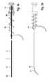
- Fig. 2shows a permanently implantable electrode lead 2 with fixed or retractable screw fixation 21 and a device 1 for the targeted permanent or temporary introduction of implants.
- the device 1is formed in this and the other embodiments as a wire and has an elongate body 10 with a fixing unit 11 which is formed as a needle-shaped and pre-bent, elastic tip.
- the fixing unit 11has a radius of min. 5mm to max. 20mm and is bent in a circular arc with an angle of 70 to 90 degrees. The orientation of the bow is freely selectable / adjustable by the user.
- the wire 1has a usual size, the approx. 0.36 mm.
- a markmay be provided, by means of which it can be determined in how far the fixing unit 11 has been extended.
- the electrode leadhas at least one pole, which can also be formed by the screw fixation, and a hollow body 20, which has a through cavity 22 with a distal and a proximal opening.
- the cavity 22is designed so that a device 1 can be guided therein.
- the electrode line 2has at the distal end a sealing unit 23 which prevents blood from entering and which can only be pierced reversibly by the fixing unit 11 of the device.
- the wire 1at the distal end of the electrode line 2 and temporarily connected to the tissues of the living being.
- the screw fixation 21is slidably mounted in a rigid housing 24 at the distal end of the electrode lead 2 so that it can perform a combined rotational / sliding movement for screwing in or out of the body tissue.
- a rotational movementwhich is performed at the proximal end of the electrode line and acts via a transmission element on the screw 21, this can be screwed in or out.
- the housing 24has an extension along the longitudinal axis of the electrode line 2 of less than 15mm.
- the electrode linehas a plug connection, with the connection unit, not shown here.
- this connection unitusually in the form of a standardized plug according to standard IS-1, DF-1 and / or IS-4, an electrical connection with an implantable or external electrical device can be made.
- theseinclude pacemakers, cardioverter / defibrillators, brain or nerve pacemakers, or other electrically active devices.
- the wire 1can be detachably connected by means of a detent 12 located on it, in order to prevent the tip from unintentionally emerging at the distal end of the electrode.
- the lockingcan be done by screws, notches or clamps.
- an externally visible markingcan be provided at the proximal end of the electrode line 2 or in its vicinity, with which it can be determined whether the electrode line has penetrated through the insertion catheter to the heart wall.
- Fig. 3a and 3bshow a further embodiment of the device 1 for the targeted permanent or temporary introduction of implants.
- the device 1 in the form of a wireruns displaceably in a guide 4 in the form of a Mandrin arrangementshülse.
- a guide 4is used to guide the electrode line 2 more easily to the implantation site and has a hollow body 40 with a continuous cavity 41 and a distal and a proximal end 42 and 43.
- the electrode lead 2additionally has at the distal end immediately proximal to the sealing unit 23 a conventional stop 25 which comprises a bore and an abutment.
- a conventional stop 25which comprises a bore and an abutment.
- the boreis designed so that the fixing unit 11 of the wire 1 can penetrate while the guide 4 abuts the abutment, which makes it possible that the electrode line can be guided by means of the guide 4.
- the guidehas an inner diameter which allows a wire with a diameter of 0.36 mm to be displaceably guided, that is an inner diameter which is slightly larger than 0.36 mm, preferably 0.4 mm.
- the guide 4at its proximal end on a lock 44, by means of which the wire 1 with the guide 4 can be releasably connected to prevent the tip unintentionally at the distal end 42 guide 4 exits.
- the wire 1 of this embodimentcan be detachably connected at its proximal end by means of a detent 12 located on the wire 1 in order to prevent displacement of the temporary composite of wire 1 and guide 4 relative to the electrode line 3.
- the locks 12 and 44can be done by screws, notches or terminals.
- the fixing unit 11 of the wire 1can extend in a defined length through the stop 25 and the seal 23 from the distal end of the electrode line and penetrate the tissue of the living being.
- Fig. 4shows a further embodiment, consisting of a guide catheter 3 as a medical implant and a device. 1
- the guide catheter 3has a double hollow body 30 with two parallel cavities 31 and 32, wherein the hollow body 31 is configured to guide the wire 1 slidably.
- the further cavity 32is designed such that it is not in connection with the cavity 31. Further, the cavity 32 is designed so that it can lead, for example, an actively fixable electrode line. Cavity 32 is also designed peel and / or slit. Both cavities are hollow throughout and form an opening at the distal and proximal ends of the catheter 3, respectively.
- a lock 33which locks the wire 1 so that it can not escape from the catheter tip unintentionally, but can be extended after loosening the lock in an adjustable length.
Landscapes
- Health & Medical Sciences (AREA)
- Heart & Thoracic Surgery (AREA)
- Cardiology (AREA)
- Engineering & Computer Science (AREA)
- Biomedical Technology (AREA)
- Nuclear Medicine, Radiotherapy & Molecular Imaging (AREA)
- Radiology & Medical Imaging (AREA)
- Life Sciences & Earth Sciences (AREA)
- Animal Behavior & Ethology (AREA)
- General Health & Medical Sciences (AREA)
- Public Health (AREA)
- Veterinary Medicine (AREA)
- Electrotherapy Devices (AREA)
Abstract
Description
Translated fromGermanDie Erfindung betrifft eine Vorrichtung zum zielgerichteten dauerhaften oder vorübergehenden Einbringen von medizinischen Implantaten in ein Lebewesen, welche einen lang gestreckten Körper mit einem distalen Ende und einem proximalen Ende umfasst, wobei die Vorrichtung ausgelegt ist, über einen Zugang in das Lebewesen geführt zu werden, so dass das proximale Ende außerhalb des Lebewesens verbleibt.The invention relates to a device for the targeted permanent or temporary introduction of medical implants into a living being, which comprises an elongate body having a distal end and a proximal end, wherein the device is designed to be guided via an access into the living being that the proximal end remains outside the living being.
Weiterhin betrifft die Erfindung ein medizinisches Implantat zum dauerhaften oder vorübergehenden Verbleib in einem Lebewesen, das einen Hohlkörper mit einem distalen und einem proximalen Ende und mit einem durchgängigen Hohlraum entlang der Längsachse des Hohlkörpers umfasst, wobei der Hohlkörper so beschaffen ist, dass er die erfindungsgemäße Vorrichtung aufnehmen und reversibel führen kann, und weiterhin jeweils einer Öffnung am proximalen und am distalen Ende umfasst, durch die die Vorrichtung dringen kann.Furthermore, the invention relates to a medical implant for permanent or temporary retention in a living being, which comprises a hollow body with a distal and a proximal end and with a continuous cavity along the longitudinal axis of the hollow body, wherein the hollow body is such that it is the device according to the invention and reversibly, and further includes an opening at each proximal and distal end through which the device can penetrate.
Solche bekannten Vorrichtungen werden eingesetzt, um Elektrodenleitungen an einen gewünschten Implantationsort in ein Lebewesen zu verbringen, wo sie dann befestigt werden. Dabei wird unter anderem zuerst ein so genannter Führungsdraht durch das venöse System in eine Herzkammer oder ein Herzkranzgefäß gelegt, entlang diesem dann eine Elektrodenleitung eingeführt und am Körpergewebe wie der Herzwand fixiert wird. Problematisch wird es dann, wenn besondere Gegenden gezielt stimuliert werden sollen. Dies ist beispielsweise der Fall, wenn der Arzt Elektrodenleitungen hochseptal in der nähe des HIS-Bündels fixieren möchte. Dort ergibt sich das Problem, dass die Elektrodenleitung in der Regel mit einem Führungskatheter an den Ort der Fixierung gebracht werden muss. Auf Grund der engen Platzverhältnisse ist es schwierig, die Elektrodenleitung durch kleine Biegeradien des Führungskatheters in das Zielgebiet zu führen. Die zunehmende Reibung zwischen der Elektrodenleitung und Führungskatheter verhindert dann ein Vorschieben. Darüber hinaus kann der Arzt die Elektrodenleitung nicht mehr ausreichend an die Herzwand andrücken, da sie in einer 90°-Stellung zur Einführachse steht und der Katheter nicht genügend Stützmöglichkeiten bietet. Deshalb ist es sehr schwierig oder oft genug unmöglich, Standard-Elektroden wie aktiv fixierbare Schraubelektroden in Bereichen des Herzens zu befestigen, in denen die Elektroden nur noch tangential oder in einem flachen Winkel auf das Herzgewebe treffen. Ein Katheter der ausreichend große Biegeradien bietet, kann aber die Elektroden nur noch in einem flachen Winkel in das Zielgebiet führen, was ein Einschrauben auf Grund des mangelnden Andrucks ebenfalls verhindert.Such known devices are used to transfer electrode leads to a desired site of implantation into a subject, where they are then attached. Among other things, a so-called guide wire is first placed through the venous system in a heart chamber or a coronary vessel, along which then an electrode line is introduced and fixed on the body tissue such as the heart wall. It becomes problematic when specific areas are to be specifically stimulated. This is the case, for example, when the physician wishes to fix electrode lines in a high-septum near the HIS bundle. There arises the problem that the electrode line must be brought to the place of fixation usually with a guide catheter. Due to the limited space, it is difficult to guide the electrode line through small bending radii of the guide catheter in the target area. The increasing friction between the electrode lead and guide catheter then prevents advancement. In addition, the doctor can no longer adequately press the electrode lead to the heart wall because it is in a 90 ° position to the insertion axis and the catheter does not provide enough support. Therefore, it is very difficult or often impossible to fix standard electrodes such as actively fixable screw electrodes in areas of the heart where the electrodes strike the heart tissue only tangentially or at a shallow angle. A catheter that offers sufficiently large bending radii, but can lead the electrodes only at a shallow angle in the target area, which also prevents screwing due to the lack of pressure.
Ebenso möglich ist es, von außen eine Elektrodenleitung mit einer ähnlichen Methode am Epikard zu befestigen. Dazu wird ein Führungskatheter durch die Brustwand eingebracht, in den dann eine Elektrodenleitung mit Fixierung geführt und an der äußeren Herzwand (Epikard) angebracht wird. Um an die Herzwand von außen heranzukommen, muss der relativ enge Raum zwischen Brustwand mit Rippen passiert werden. Deshalb kann die Elektrodenleitung dort nicht im rechten Winkel eingebracht werden, sondern es muss versucht werden, die Elektrode tangential an die Herzwand heranzuführen und dann zu befestigen. Eine handelsübliche Einschraubelektrodenleitung kann dann nicht mehr befestigt werden.It is also possible to attach an electrode line to the epicard from the outside using a similar method. For this purpose, a guide catheter is inserted through the chest wall, in which then an electrode lead with fixation and attached to the outer heart wall (epicardium) is attached. In order to get to the heart wall from the outside, the relatively narrow space between chest wall must be passed with ribs. Therefore, the electrode lead can not be inserted there at right angles, but it must be attempted to bring the electrode tangentially to the heart wall and then secure it. A commercially available Einschraubelektrodenleitung can then no longer be attached.
Es ist daher Aufgabe der vorliegenden Erfindung, eine Vorrichtung und damit zusammenwirkendes medizinisches Implantat zu schaffen, das sicherstellt, dass ein möglichst handelsübliches Implantat sicher und zielgerichtet an einem Körpergewebe so befestigt werden kann, dass der Anwender die Befestigung während des Einbringens und Befestigens der Elektrode gewährleisten kann.It is therefore an object of the present invention to provide a device and cooperating medical implant, which ensures that a commercially available implant can be securely and accurately attached to a body tissue so that the user ensure the attachment during insertion and securing the electrode can.
Diese Aufgabe wird durch die Vorrichtung aus Anspruch 1 und das medizinische Implantat aus Anspruch 8 gelöst.This object is achieved by the device of
Der erste Aspekt der Aufgabe wird durch eine Vorrichtung zum zielgerichteten dauerhaften oder vorübergehenden Einbringen von medizinischen Implantaten in ein Lebewesen gelöst, welche einen lang gestreckten Körper mit einem distalen Ende und einem proximalen Ende umfasst. Dabei ist die Vorrichtung so ausgelegt, dass es über einen Zugang in das Lebewesen geführt werden kann, so dass das proximale Ende außerhalb des Lebewesens verbleibt und dass das distale Ende eine Fixierungseinrichtung aufweist, mit der die Vorrichtung lösbar mit dem Körpergewebe fest verbunden werden kann. Vorzugsweise ist die Fixierungseinrichtung dafür ausgebildet, in das Körpergewebe einzudringen, also vorzugsweise angespitzt und besonders bevorzugt nadelförmig. Damit ist der distale Bereich der Vorrichtung am Myokard temporär fixiert, indem die Fixiervorrichtung im Körpergewebe eingedrungen ist. Über die so fixierte Vorrichtung kann dann ein medizinisches Implantat gezielt im Gewebe fixiert werden. Das Implantat zum dauerhaften oder vorübergehenden Verbleib in einem Lebewesen umfasst dabei einen durchgängig hohlen Hohlkörper entlang einer Längsachse mit einem distalen und einem proximales Ende, wobei der Hohlkörper so beschaffen ist, dass er die erfindungsgemäße Vorrichtung aufnehmen und reversibel führen kann, und jeweils einer Öffnung am proximalen und am distalen Ende, durch die die Vorrichtung dringen kann, wobei die Öffnung am distalen Ende eine von der Fixierungseinrichtung der Vorrichtung reversibel durchstoßbare Dichteinheit zur Abdichtung des durchgängig hohlen Hohlkörpers aufweist.The first aspect of the object is achieved by a device for the targeted permanent or temporary introduction of medical implants into a living being, which comprises an elongated body with a distal end and a proximal end. In this case, the device is designed so that it can be guided via an access into the living being, so that the proximal end remains outside the living being and that the distal end has a fixing device with which the device can be releasably connected to the body tissue. Preferably, the fixing device is designed to penetrate into the body tissue, thus preferably sharpened and particularly preferably acicular. Thus, the distal region of the device is temporarily fixed to the myocardium by the fixation device has penetrated into the body tissue. About the thus fixed device then a medical implant can be selectively fixed in the tissue. The implant for permanent or temporary whereabouts in a living being comprises a hollow body which is hollow throughout along a longitudinal axis with a distal and a proximal end, wherein the hollow body is adapted to receive the device according to the invention and to guide it reversibly, and in each case to an opening on the proximal and at the distal end, through which the device can penetrate, the opening at the distal end having a reversibly pierceable by the fixing device of the device sealing unit for sealing the hollow body continuously hollow.
Gemäß einer weiteren bevorzugten Ausgestaltung weist die Fixierungseinrichtung eine in laterale Richtung erstreckende Vorbiegung auf, welche vorzugsweise einen Radius von 5 mm bis 20 mm und/oder einen Kreisbogen mit einem Winkel von 70° bis 90° im Winkelmaß aufweist. Dadurch kann das Implantat über die Vorrichtung zum Implantationsort gebracht werden, indem es beispielsweise im engen Raum zwischen Brustkorb und Perikard geführt wird, dann im besonders engen Raum im Perikard tangential raumsparend an das Epikard geführt und anschließend mit einem angemessenen Winkel auf das Myokard befestigen wird. So lassen sich die notwendigen Penetrationskräfte auf das Implantat aufbringen, ohne dass sie ausweichen kann.According to a further preferred embodiment, the fixing device has a pre-bend extending in the lateral direction, which preferably has a radius of 5 mm to 20 mm and / or a circular arc with an angle of 70 ° to 90 ° in the angular dimension. As a result, the implant can be brought to the implantation site via the device, for example, guided between the thorax and the pericardium in a narrow space, then guided tangentially to the epicardium in a particularly narrow space in the pericardium and then fastened onto the myocardium at an appropriate angle. This allows the necessary penetration forces to be applied to the implant without being able to avoid it.
Um die Herstellung zu erleichtern und herkömmliche Implantate verwenden zu können, weißt die Vorrichtung herkömmliche Eigenschaften auf, wie beispielsweise, dass der Körper und die Fixierungseinrichtung elastisch sind, vorzugsweise bestehend aus einem Draht, besonders bevorzugt aus einem Draht mit einem Durchmesser von kleiner gleich 0,36 mm.In order to facilitate the manufacture and to be able to use conventional implants, the device has conventional properties, such as that the body and the fixing device are elastic, preferably made of a wire, more preferably of a wire with a diameter of less than or equal to 0, 36 mm.
Um beim Einführen der Vorrichtung Verletzungen zu vermeiden weist die Vorrichtung vorzugsweise am proximalen Ende eine Arretierungsvorrichtung auf, welche eine lösbare Arretierung mittel- oder unmittelbar mit dem medizinischen Implantat ermöglicht. Dadurch wird die Lage zwischen Vorrichtung und medizinischen Implantat eingestellt oder eine Verschiebung zwischen Vorrichtung und Implantat verhindert.In order to avoid injuries when inserting the device, the device preferably has a locking device on the proximal end, which enables a releasable locking means directly or indirectly with the medical implant. As a result, the position between the device and the medical implant is adjusted or a displacement between the device and the implant is prevented.
Gemäß einer zusätzlichen Form umfasst die Vorrichtung weiter eine Führung zur reversiblen Führung oder Halterung der Vorrichtung, welche einen lang gestreckten Hohlkörper mit einem distalen und einem proximalen Ende mit einem durchgängigen Hohlraum entlang einer Längsachse aufweist, wobei der Hohlkörper so beschaffen ist, dass er die Vorrichtung aufnehmen und reversibel führen und/oder haltern kann. Weiter umfasst die Führung jeweils eine Öffnung am proximalen und am distalen Ende, welche mit dem Hohlraum des Hohlkörpers verbunden sind und durch die die Vorrichtung dringen kann, und eine Arretierungseinheit am proximalen Ende, welche eine lösbare Arretierung mittel- oder unmittelbar mit der Vorrichtung ermöglicht, um die Lage zwischen Vorrichtung und Führung einzustellen oder eine Verschiebung zwischen Vorrichtung und Führung zu verhindern. Vorzugsweise ist die Führung als Hülse, vorzugsweise als elastische biegbare Mandrinhülse ausgebildet. Dadurch kann das Einführen eines Implantates weiter verbessert werden, da dann die Vorrichtung gestützt und wesentlich stabiler ist. Weiterhin kann durch die zusätzliche Führung das Einführen und Platzieren der Elektrodenleitung wesentlich vereinfacht werden.According to an additional form, the device further comprises a guide for reversibly guiding or holding the device, which has an elongate hollow body with a distal and a proximal end with a continuous cavity along a longitudinal axis, wherein the hollow body is such that it forms the device can record and reversibly lead and / or support. Furthermore, the guide comprises in each case an opening at the proximal and at the distal end, which are connected to the hollow space of the hollow body and through which the device can penetrate, and a locking unit at the proximal end which enables a releasable locking directly or indirectly with the device, to adjust the position between the device and the guide or to prevent a shift between the device and the guide. Preferably, the guide is formed as a sleeve, preferably as an elastic bendable Mandrinhülse. As a result, the insertion of an implant can be further improved, since then the device is supported and much more stable. Furthermore, the insertion and placement of the electrode line can be significantly simplified by the additional guide.
Der zweite Aspekt der Aufgabe wird durch ein medizinisches Implantat zum dauerhaften oder vorübergehenden Verbleib in einem Lebewesen gelöst welches einen Hohlkörper mit einem distalen und einem proximalen Ende und einem durchgängigen Hohlraum entlang einer Längsachse gelöst. Der Hohlkörper ist dabei so beschaffen, dass er die Vorrichtung zum zielgerichteten dauerhaften oder vorübergehenden Einbringen von medizinischen Implantaten in ein Lebewesen aufnehmen und reversibel führen kann. Der Hohlraum weist jeweils eine mit ihm verbundene Öffnung am proximalen und am distalen Ende auf, durch die die Vorrichtung dringen kann. Die Öffnung am distalen Ende weist dabei eine von der Fixierungseinrichtung der Vorrichtung zum zielgerichteten dauerhaften oder vorübergehenden Einbringen von medizinischen Implantaten in ein Lebewesen reversibel durchstoßbare Dichteinheit zur Abdichtung des Hohlkörpers auf.The second aspect of the object is achieved by a medical implant for permanent or temporary retention in a living being which disengages a hollow body having a distal and a proximal end and a continuous cavity along a longitudinal axis. The hollow body is designed such that it can receive the device for the purposeful permanent or temporary introduction of medical implants into a living being and reversible. Each cavity has an opening connected thereto at the proximal and distal ends through which the device can pass. In this case, the opening at the distal end has a sealing unit which can be reversibly pierced by the fixing device of the device for the purposeful permanent or temporary introduction of medical implants into a living being for sealing the hollow body.
Vorteilig ist an dem medizinischen Implantat, dass es so wenig wie möglich Anpassungen erfährt, um mit der erfindungsgemäßen Vorrichtung eingebracht werden zu können. So weist das Implantat vorzugsweise eine sich in seinem Hohlkörper unmittelbar proximal vor der Dichteinheit befindliche Anschlageinrichtung mit einer Bohrung und einem Widerlager auf, welche so ausgestaltet ist, dass die Fixierungseinrichtung der Vorrichtung die Bohrung durchdringen kann und die Führung am Widerlager anschlägt. Das ermöglicht das Führen des Implantats mit der Führung bzw. mit der Mandrinhülse, welche bei einer Kraftauswirkung entlang der Längsachse in distale Richtung am Widerlager anschlägt. Bei weiterer Kraftaufbringung wird das Implantat, welches durchaus aus sehr biegeweichem oder dünnem Material besteht, in distale Richtung getrieben, bis es am Implantationsort angelangt und dort fixiert werden kann.It is advantageous to the medical implant that it undergoes as little as possible adjustments in order to be able to be introduced with the device according to the invention can. Thus, the implant preferably has an in his hollow body immediately proximal of the sealing unit located stop device with a bore and an abutment which is designed so that the fixing device of the device can penetrate the bore and the guide strikes the abutment. This makes it possible to guide the implant with the guide or with the stylet sleeve, which in a Force impact along the longitudinal axis in the distal direction abuts the abutment. Upon further application of force, the implant, which is entirely made of very flexible or thin material, is driven in the distal direction until it reaches the implantation site and can be fixed there.
Bevorzugt handelt es sich bei dem medizinischen Implantat um eine medizinische Elektrodenleitung, welche am distalen Ende mindestens einen elektrischen Pol zur Abgabe elektrischer Pulse auf das Körpergewebe des Lebewesens, mindestens einen mit jeweils einem dieser Pole elektrisch verbundenen Leiter, der sich vom jeweiligen Pol zum proximalen Ende erstreckt, und einer Anschlusseinheit am proximalen Ende, welche mit jedem der elektrischen Leiter verbunden ist, um eine elektrische Verbindung mit einem implantierbaren oder externen elektrischen Gerät herzustellen, umfasst. Solche Elektrodenleitungen werden in der modernen Medizin in vielfältiger Form eingesetzt. Sie können beispielsweise wie beschrieben in oder an einem Herzen angewandt werden, um die sichere Funktion des Herzens unmittelbar sicherstellen zu können. Weiterhin sind Elektrodenleitungen umfasst, die auch im Nervensystem oder in einem Gehirn eingesetzt werden. Diese Leitungen müssen extrem filigran sein, weshalb beispielsweise die Führung entlang einer Mandrinhülse von herausragender Wichtigkeit ist.The medical implant is preferably a medical electrode lead, which at the distal end has at least one electrical pole for delivering electrical pulses to the body tissue of the living being, at least one conductor electrically connected to one of these poles extending from the respective pole to the proximal end and a terminal unit at the proximal end connected to each of the electrical conductors to make electrical connection with an implantable or external electrical device. Such electrode lines are used in modern medicine in many forms. For example, they may be applied in or on a heart as described to directly assure the safe functioning of the heart. Furthermore, electrode lines are included, which are also used in the nervous system or in a brain. These lines must be extremely delicate, which is why, for example, the leadership along a Mandrinhülse is of paramount importance.
Bevorzugt ist diese Elektrodenleitung eine dauerhaft implantierbare Schraubelektrode mit einer festen oder zurückziehbaren Schraubfixierung am distalen Ende, wobei die Schraubfixierung vorzugsweise einen der elektrischen Pole bildet. Besonders bevorzugt wird die Schraubfixierung in einer Schraubenführung geführt, welche sich am distalen Ende befindet und die distale Öffnung radial zumindest teilweise umgibt. Dadurch wird die Elektrodenleitung auch unter schwierigsten Platzbedingungen leicht implantierbar.Preferably, this electrode lead is a permanently implantable screw electrode with a fixed or retractable screw fixation at the distal end, wherein the screw fixation preferably forms one of the electrical poles. Particularly preferably, the screw fixing is guided in a screw guide, which is located at the distal end and radially surrounds the distal opening at least partially. As a result, the electrode lead is easily implanted even under the most difficult space conditions.
Gemäß einer weiteren Alternative ist das medizinische Implantat als Führungskatheter ausgelegt und umfasst neben dem Hohlraum zur Führung der erfindungsgemäßen Vorrichtung einen zweiten durchgängig hohlen Hohlraum entlang ein- und derselben Längsachse mit einem distalen und einem proximalen Ende, wobei der Hohlraum so beschaffen ist, dass er ein medizinisches Gerät aufnehmen und führen und/oder haltern kann. Der Hohlraum bildet jeweils eine weitere Öffnung am proximalen und am distalen Ende aus, durch die das medizinische Gerät dringen kann. Weiterhin umfasst der Führungskatheter eine Arretierungseinheit am proximalen Ende, welche eine lösbare Arretierung mittel- oder unmittelbar mit der Vorrichtung ermöglicht, um die Lage zwischen Vorrichtung und Führung einzustellen oder eine Verschiebung zwischen Vorrichtung und Führung zu verhindern. Der zweite Hohlraum ist geeignet, um beispielsweise eine Elektrodenleitung zielgerichtet platzieren zu können. Es ist auch vorstellbar, eine gezielte Einführung anderer therapeutischer Implantate zu ermöglichen, beispielsweise Medikamentenkatheter oder Katheter, mit deren Hilfe Gewebe entnommen werden kann oder um beispielsweise Körperlumen offen zu halten oder zu eröffnen. Weiterhin kann ein solcher Katheter auch vorgesehen sein, um beispielsweise Sensoren oder Medikamentendepots zielgerichtet platzieren zu können.According to a further alternative, the medical implant is designed as a guide catheter and comprises in addition to the cavity for guiding the device according to the invention a second hollow cavity along one and the same longitudinal axis with a distal and a proximal end, wherein the cavity is such that it is a can receive and guide and / or support medical equipment. The cavity each forms a further opening at the proximal and distal ends, through which the medical device can penetrate. Furthermore, the guide catheter comprises a locking unit at the proximal end, which enables a releasable locking medium or directly with the device to the position between the device and guide or to prevent a shift between the device and the guide. The second cavity is suitable for being able to place, for example, an electrode line in a targeted manner. It is also conceivable to enable a targeted introduction of other therapeutic implants, for example medicament catheters or catheters, with the aid of which tissue can be removed or, for example, to keep body lumens open or open. Furthermore, such a catheter can also be provided in order to be able to place sensors or drug depots in a targeted manner, for example.
Um den Führungskatheter auch zur Implantation von Elektrodenleitungen einsetzen zu können, welche eine relativ große Anschlusseinrichtung zum Anschluss an ein implantierbares oder externes medizinisches Gerät aufweisen, ist der Hohlkörper peel- oder schlitzbar, so dass die Seitenwand des Hohlraums enlang der Längsachse geöffnet wird. Dadurch ist es möglich, nach der erfolgreichen Fixierung des Implantats den zweiten Hohlraum komplett entlang der Längsachse zu eröffnen, um den Katheter dann nach Freigabe der Fixiereinrichtung der erfindungsgemäßen Vorrichtung komplett zu entnehmen, wobei das Implantat im Körper verbleibt.In order to be able to use the guide catheter also for the implantation of electrode leads, which have a relatively large connection device for connection to an implantable or external medical device, the hollow body is peelable or slit, so that the side wall of the cavity is opened along the longitudinal axis. This makes it possible, after the successful fixation of the implant to open the second cavity completely along the longitudinal axis to completely remove the catheter after release of the fixing device of the device according to the invention, wherein the implant remains in the body.
Weitere Ziele, Merkmale, Vorteile und Anwendungsmöglichkeiten der Erfindung ergeben sich aus der nachfolgenden Beschreibung von Ausführungsbeispielen anhand der Figuren. Dabei bilden alle beschriebenen und/oder bildlich dargestellten Merkmale für sich oder in beliebiger Kombination den Gegenstand der vorliegenden Erfindung, unabhängig von ihrer Zusammenfassung in den einzelnen Ansprüchen oder deren Rückbeziehungen. Es zeigen:
- Fig. 1a, Fig. 1b
- Prinzipielle Darstellung der temporären Befestigung mit einer Vor- richtung nach
Anspruch 1 - Fig. 2
- das distale Ende eines Ausführungsbeispiels der Vorrichtung nach Anspruch 1 mit einer aktiv fixierbaren Elektrodenleitung
- Fig. 3a, Fig. 3b
- ein zweites Ausführungsbeispiel der Vorrichtung mit einer aktiv fi- xierbaren Elektrodenleitung und einer Mandrinhülse
- Fig. 4
- das distale Ende eines dritten Ausführungsbeispiels der Vorrichtung mit einem Führungskatheter
- Fig. 1a, Fig. 1b
- Schematic representation of the temporary attachment with a device according to
claim 1 - Fig. 2
- the distal end of an embodiment of the device according to
claim 1 with an actively fixable electrode line - Fig. 3a, Fig. 3b
- A second embodiment of the device with an actively fixable electrode line and a Mandrinhülse
- Fig. 4
- the distal end of a third embodiment of the device with a guide catheter
In
Nachdem der Sheet 6 an der gewünschten Stelle liegt, wird eine Vorrichtung 1 mit eine Fixierungseinrichtung 11 durch den Hohlraum 22 des Hohlkörpers 20 in die Elektrodenleitung 2 geschoben. Die Vorrichtung 1 wird dann mit Hilfe der Arretierung 12 so fixiert, dass die Fixierungseinrichtung 11 so im Hohlraum 22 zum liegen kommt, dass sie nicht lateral aus der Elektrodenleitung heraussteht. In diesem Zustand werden die befestigte Vorrichtung 1 und die Elektrodenleitung 2 bis zum distalen Ende 61 des Sheets 6 durch den Hohlkörper 60 vorgeschoben. Ist das distale Ende der Elektrodenleitung am distalen Ende 61 des Sheets 6 angelangt, wird die Elektrodenleitung 2 mit geeigneten Mitteln mit dem Sheet lösbar verbunden, während die Arretierung 12 der Vorrichtung geöffnet wird. Nun kann die vorgebogene und angespitzte Fixierungseinrichtung 11 aus der distalen und lateralen Öffnung des Sheets 6 heraustreten und mit einer definierten Eindringtiefe in das Epikard 101 eindringen und dort befestigt werden. Durch diese Befestigung und die Vorbiegung der Fixierungseinrichtung 11 bildet sich ein Bogen aus, der in einem Winkel von 70 bis 90 Grad in das Epikard 101 eindringt. Jetzt kann die Elektrodenleitung 2 vorgeschoben werden und kann bedingt durch den eingestellten Winkel befestigt werden, da die Schraubfixierung 21 der Elektrodenleitung 2 jetzt die Möglichkeit zum Eingriff in das Epikard hat.After the
Nach Befestigung der Elektrodenleitung 2 wird die Fixierungseinrichtung 11 aus dem Epikard 101 gezogen und die Vorrichtung 1 zusammen mit dem Sheet 6 entfernt.After fixing the
Die Vorrichtung 1 ist in diesem und den anderen Ausführungen als Draht ausgebildet und weist einen lang gestreckten Körper 10 mit einer Fixierungseinheit 11 auf, die als nadelförmige und vorgebogene, elastische Spitze gebildet ist. Die Fixierungseinheit 11 weist einen Radius von min 5mm bis max. 20mm auf und ist in einem Kreisbogen mit einem Winkel von 70 bis 90 Grad gebogen. Die Orientierung des Bogens ist vom Anwender frei wählbar/einstellbar ist. Im Durchmesser weist der Draht 1 eine übliche Größe auf, die circa. 0,36 mm beträgt. An der Vorrichtung 1 kann eine Markierung vorgesehen sein, mit Hilfe derer festgestellt werden kann, in wie weit die Fixiereinheit 11 ausgefahren wurde.The
Die Elektrodenleitung weist mindestens einen Pol, der auch von der Schraubfixierung gebildet werden kann, und einen Hohlkörper 20 auf, der einen durchgehenden Hohlraum 22 mit einer distalen und einer proximalen Öffnung aufweist. Der Hohlraum 22 ist so ausgelegt, dass eine Vorrichtung 1 darin geführt werden kann.The electrode lead has at least one pole, which can also be formed by the screw fixation, and a
Weiter weist die Elektrodenleitung 2 am distalen Ende eine Dichteinheit 23 auf, die verhindert, dass Blut eintreten kann und die nur von der Fixierungseinheit 11 der Vorrichtung reversibel durchstoßen werden kann. So kann der Draht 1 am distalen Ende der Elektrodenleitung 2 austreten und vorübergehend mit dem Gewebe des Lebewesens verbunden werden.Furthermore, the
Die Schraubfixierung 21 ist in einem starren Gehäuse 24 am distalen Ende der Elektrodenleitung 2 gleitend befestigt, so dass sie eine kombinierte Dreh-/Gleitbewegung zum Ein- oder Ausschrauben aus dem Körpergewebe ausführen kann. Durch eine Drehbewegung, die am proximalen Ende der Elektrodenleitung durchgeführt wird und über ein Übertragungselement auf die Schraubfixierung 21 wirkt, kann diese ein- oder ausgeschraubt werden. Das Gehäuse 24 hat dabei eine Ausdehnung entlang der Längsachse der Elektrodenleitung 2 von kleiner 15mm.The
An seinem proximalen Ende weist die Elektrodenleitung eine Steckverbindung auf, mit der einer hier nicht dargestellten Anschlusseinheit. Mit dieser Anschlusseinheit, meist in Form eines normierten Steckers gemäß Standard IS-1, DF-1 und/oder IS-4, kann eine elektrische Verbindung mit einem implantierbaren oder externen elektrischen Gerät hergestellt werden. Dabei handelt es sich im Herzschrittmacher, Cardioverter/Defibrillatoren, Hirn-oder Nervenschrittmacher oder andere elektrisch aktive Geräte.At its proximal end, the electrode line has a plug connection, with the connection unit, not shown here. With this connection unit, usually in the form of a standardized plug according to standard IS-1, DF-1 and / or IS-4, an electrical connection with an implantable or external electrical device can be made. These include pacemakers, cardioverter / defibrillators, brain or nerve pacemakers, or other electrically active devices.
An diesem proximalen Ende der Elektrodenleitung 2 kann der Draht 1 mittels einer an ihm befindlichen Arretierung 12 lösbar verbunden werden, um zu verhindern, dass die Spitze ungewollt am distalen Ende der Elektrode austritt. Die Arretierung kann durch Schrauben, Rasten oder Klemmen erfolgen. Weiterhin kann am proximalen Ende der Elektrodenleitung 2 oder in dessen Nähe eine von außen sichtbare Markierung vorgesehen sein, mit der festgestellt werden kann, ob die Elektrodenleitung durch den Einführkatheter bis zur Herzwand vorgedrungen ist.At this proximal end of the
Die Vorrichtung 1 in Form eines Drahtes verläuft dabei verschiebbar in einer Führung 4 in Form einer Mandrinführungshülse. Eine solche Führung 4 wird dazu verwendet, die Elektrodenleitung 2 leichter an den Implantationsort zu führen und weist einen Hohlkörper 40 mit einem durchgängigen Hohlraum 41 und einem distalen und einem proximalen Ende 42 und 43 auf.The
Damit die Elektrodenleitung geführt werden kann, weist die Elektrodenleitung 2 zusätzlich am distalen Ende unmittelbar proximal der Dichteinheit 23 einen üblichen Anschlag 25 auf, der eine Bohrung und ein Widerlager umfasst. Ein solcher Anschlag ist beispielsweise aus der
Auch der Draht 1 dieses Ausführungsbeispiels kann an seinem proximalen Ende mittels einer am Draht 1 befindlichen Arretierung 12 lösbar verbunden werden, um eine Verschiebung des vorübergehenden Verbundes aus Draht 1 und Führung 4 relativ zur Elektrodenleitung 3 zu verhindern. Auch hier können die Arretierungen 12 und 44 durch Schrauben, Rasten oder Klemmen erfolgen. Nach dem Lösen der Arretierung 45 kann die Fixierungseinheit 11 des Drahtes 1 in definierter Länge durch den Anschlag 25 und die Dichtung 23 aus dem distalen Ende der Elektrodenleitung ausfahren und im Gewebe des Lebewesens eindringen.Also, the
Der Führungskatheter 3 weist einen Doppel-Hohlkörper 30 mit zwei parallel verlaufenden Hohlräumen 31 und 32 auf, wobei der Hohlkörper 31 ausgestaltet ist, den Draht 1 verschiebbar zu führen. Der weitere Hohlraum 32 ist ausgestaltet, dass der nicht in Verbindung mit dem Hohlraum 31 steht. Weiter ist der Hohlraum 32 so gestaltet, dass er beispielsweise eine aktiv fixierbare Elektrodenleitung führen kann. Hohlraum 32 ist weiterhin peel- und/oder schlitzbar gestaltet. Beide Hohlräume sind durchgehend hohl und bilden jeweils am distalen und proximalen Ende des Katheters 3 eine Öffnung aus.The guide catheter 3 has a double
An seinem proximalen Ende weist der Führungskatheter 3 eine Arretierung 33 auf, die den Draht 1 so arretiert, dass er nicht aus der Katheterspitze ungewollt austreten kann, aber nach lösen der Arretierung in einer einstellbaren Länge ausgefahren werden kann.At its proximal end, the guide catheter 3, a lock 33 which locks the
Claims (14)
Translated fromGermandadurch gekennzeichnet, dass
das distale Ende eine Fixierungseinrichtung (11) aufweist, mit der die Vorrichtung lösbar mit dem Körpergewebe (101) fest verbunden werden kann.Device (1) for the targeted permanent or temporary introduction of medical implants (2, 3) into a living being, which comprises an elongate body having a distal end and a proximal end, the device being designed to be guided through an access into the living being to become so that the proximal end remains outside the living being,
characterized in that
the distal end has a fixing device (11) with which the device can be detachably connected to the body tissue (101) in a detachable manner.
die Öffnung am distalen Ende eine von der Fixierungseinrichtung (11) der Vorrichtung reversibel durchstoßbare Dichteinheit (23) zur Abdichtung des Hohlkörpers aufweist.Medical implant (2, 3) for permanent or temporary retention in a living being, comprising
the opening at the distal end has a sealing unit (23) which can be reversibly penetrated by the fixing device (11) of the device for sealing the hollow body.
Applications Claiming Priority (1)
| Application Number | Priority Date | Filing Date | Title |
|---|---|---|---|
| DE102008043452ADE102008043452A1 (en) | 2008-11-04 | 2008-11-04 | Device for introducing medical implants |
Publications (1)
| Publication Number | Publication Date |
|---|---|
| EP2181656A1true EP2181656A1 (en) | 2010-05-05 |
Family
ID=41507845
Family Applications (1)
| Application Number | Title | Priority Date | Filing Date |
|---|---|---|---|
| EP09174333AWithdrawnEP2181656A1 (en) | 2008-11-04 | 2009-10-28 | Device for inserting medical implants |
Country Status (2)
| Country | Link |
|---|---|
| EP (1) | EP2181656A1 (en) |
| DE (1) | DE102008043452A1 (en) |
Families Citing this family (1)
| Publication number | Priority date | Publication date | Assignee | Title |
|---|---|---|---|---|
| IT201800010311A1 (en)* | 2018-11-14 | 2020-05-14 | Pfm Medical Ag | SYSTEM FOR THE CONNECTION OF A MEDICAL IMPLANT TO AN INSERTION AID |
Citations (10)
| Publication number | Priority date | Publication date | Assignee | Title |
|---|---|---|---|---|
| US4884567A (en)* | 1987-12-03 | 1989-12-05 | Dimed Inc. | Method for transvenous implantation of objects into the pericardial space of patients |
| US5009229A (en)* | 1989-12-06 | 1991-04-23 | Medtronic, Inc. | Steroid eluting intramuscular lead |
| US5683447A (en)* | 1995-12-19 | 1997-11-04 | Ventritex, Inc. | Lead with septal defibrillation and pacing electrodes |
| US6493591B1 (en)* | 2000-07-19 | 2002-12-10 | Medtronic, Inc. | Implantable active fixation lead with guidewire tip |
| US20030093104A1 (en)* | 1999-10-29 | 2003-05-15 | Bonner Matthew D. | Methods and apparatus for providing intra-pericardial access |
| US20050027342A1 (en)* | 2003-07-30 | 2005-02-03 | Medtronic, Inc. | Multi-lumen medical electrical lead body |
| US20050165466A1 (en)* | 1999-10-29 | 2005-07-28 | Medtronic, Inc. | Methods and systems for accessing the pericardial space |
| US20060247751A1 (en)* | 2005-04-28 | 2006-11-02 | Seifert Kevin R | Guide catheters for accessing cardiac sites |
| EP1878462A1 (en)* | 2006-07-13 | 2008-01-16 | BIOTRONIK CRM Patent AG | Insertion device |
| WO2008011626A1 (en)* | 2006-07-21 | 2008-01-24 | Boston Scientific Scimed, Inc. | Delivery of cardiac stimulation devices |
Family Cites Families (11)
| Publication number | Priority date | Publication date | Assignee | Title |
|---|---|---|---|---|
| US5431168A (en)* | 1993-08-23 | 1995-07-11 | Cordis-Webster, Inc. | Steerable open-lumen catheter |
| AU709081B2 (en)* | 1996-02-15 | 1999-08-19 | Biosense, Inc. | Medical procedures and apparatus using intrabody probes |
| US6248112B1 (en)* | 1998-09-30 | 2001-06-19 | C. R. Bard, Inc. | Implant delivery system |
| DE10217509A1 (en) | 2002-04-19 | 2003-11-06 | Biotronik Mess & Therapieg | Cardiovascular catheter |
| US20050273146A1 (en)* | 2003-12-24 | 2005-12-08 | Synecor, Llc | Liquid perfluoropolymers and medical applications incorporating same |
| DE102004011217B4 (en)* | 2004-03-04 | 2006-11-30 | Dr. Osypka Gmbh | Device for implanting a pacemaker and / or defibrillation electrode |
| US7288104B2 (en)* | 2004-06-25 | 2007-10-30 | Cardiac Pacemakers, Inc. | Endocardial splint and method therefor |
| DE102004035903A1 (en)* | 2004-07-20 | 2006-02-16 | Biotronik Vi Patent Ag | Fixing device for implantable electrodes and catheters has a structural element of a biodegradable magnesium-based alloy especially containing rare earth elements and yttrium |
| US8019438B2 (en)* | 2005-06-28 | 2011-09-13 | Cardiac Pacemakers, Inc. | Anchor for electrode delivery system |
| US8388680B2 (en)* | 2006-10-18 | 2013-03-05 | Guided Delivery Systems, Inc. | Methods and devices for catheter advancement and delivery of substances therethrough |
| US20080147168A1 (en)* | 2006-12-04 | 2008-06-19 | Terrance Ransbury | Intravascular implantable device having detachable tether arrangement |
- 2008
- 2008-11-04DEDE102008043452Apatent/DE102008043452A1/ennot_activeWithdrawn
- 2009
- 2009-10-28EPEP09174333Apatent/EP2181656A1/ennot_activeWithdrawn
Patent Citations (10)
| Publication number | Priority date | Publication date | Assignee | Title |
|---|---|---|---|---|
| US4884567A (en)* | 1987-12-03 | 1989-12-05 | Dimed Inc. | Method for transvenous implantation of objects into the pericardial space of patients |
| US5009229A (en)* | 1989-12-06 | 1991-04-23 | Medtronic, Inc. | Steroid eluting intramuscular lead |
| US5683447A (en)* | 1995-12-19 | 1997-11-04 | Ventritex, Inc. | Lead with septal defibrillation and pacing electrodes |
| US20030093104A1 (en)* | 1999-10-29 | 2003-05-15 | Bonner Matthew D. | Methods and apparatus for providing intra-pericardial access |
| US20050165466A1 (en)* | 1999-10-29 | 2005-07-28 | Medtronic, Inc. | Methods and systems for accessing the pericardial space |
| US6493591B1 (en)* | 2000-07-19 | 2002-12-10 | Medtronic, Inc. | Implantable active fixation lead with guidewire tip |
| US20050027342A1 (en)* | 2003-07-30 | 2005-02-03 | Medtronic, Inc. | Multi-lumen medical electrical lead body |
| US20060247751A1 (en)* | 2005-04-28 | 2006-11-02 | Seifert Kevin R | Guide catheters for accessing cardiac sites |
| EP1878462A1 (en)* | 2006-07-13 | 2008-01-16 | BIOTRONIK CRM Patent AG | Insertion device |
| WO2008011626A1 (en)* | 2006-07-21 | 2008-01-24 | Boston Scientific Scimed, Inc. | Delivery of cardiac stimulation devices |
Also Published As
| Publication number | Publication date |
|---|---|
| DE102008043452A1 (en) | 2010-05-06 |
Similar Documents
| Publication | Publication Date | Title |
|---|---|---|
| DE69717873T2 (en) | Medical electrical lead with fastening part and tool for screwing in | |
| EP2956071B1 (en) | Set for peripheral nerve blocking | |
| DE60318158T2 (en) | Device for advancing a functional element through tissue | |
| DE4335098B4 (en) | Electrode feed line with holding element for a guide rod and its use | |
| DE4402058C1 (en) | Implantable temporary electrode cable | |
| DE10100976C2 (en) | Catheter for nerve block | |
| DE4244690C2 (en) | Insertion mechanism for a fetal scalp electrode | |
| DE3825631A1 (en) | DEVICE FOR TRANSVENOUS OR ARTERIAL INSERTION BY MEANS OF A GUIDE WIRE | |
| EP1260186B1 (en) | Needle assembly for blocking peripheral nerves | |
| DE2917173A1 (en) | DEVICE FOR ATTACHING AN ELECTRODE TO BODY TISSUE | |
| DE2755179A1 (en) | DEVICE FOR ATTACHING A MEASURING HEAD | |
| DE29820525U1 (en) | Catheter set for plexus anesthesia | |
| EP2281600B1 (en) | Device for defibrillating a heart | |
| DE202017002009U1 (en) | System for inserting a tracheostomy tube into a tracheostoma | |
| EP3415197A1 (en) | Electrode wire and a system for implanting such an electrode wire | |
| DE10205721A1 (en) | Guide wire and implantable lead | |
| DE3536823A1 (en) | ELECTRIC ELECTRODE AND A METHOD FOR ATTACHING THE ELECTRODE TO BONE TISSUE | |
| DE3906598A1 (en) | CONNECTING DEVICE FOR A HEART PACER ELECTROD lead | |
| AT512534A4 (en) | Nerve cuff electrode assembly | |
| EP2110156B1 (en) | Field decoupling element for use with an implantable lead and implantable medical device | |
| EP1110578B1 (en) | Dual chamber single-pass electrode assembly | |
| DE102007039553B4 (en) | Pacemaker electrode with helical coil | |
| EP2181656A1 (en) | Device for inserting medical implants | |
| DE102013001021B4 (en) | External pacemaker with an electrode connected via a connector and temporarily connectable to a heart | |
| DE19959655B4 (en) | Surgical electrode |
Legal Events
| Date | Code | Title | Description |
|---|---|---|---|
| PUAI | Public reference made under article 153(3) epc to a published international application that has entered the european phase | Free format text:ORIGINAL CODE: 0009012 | |
| AK | Designated contracting states | Kind code of ref document:A1 Designated state(s):AT BE BG CH CY CZ DE DK EE ES FI FR GB GR HR HU IE IS IT LI LT LU LV MC MK MT NL NO PL PT RO SE SI SK SM TR | |
| AX | Request for extension of the european patent | Extension state:AL BA RS | |
| STAA | Information on the status of an ep patent application or granted ep patent | Free format text:STATUS: THE APPLICATION IS DEEMED TO BE WITHDRAWN | |
| 18D | Application deemed to be withdrawn | Effective date:20101106 |