EP2181262B1 - Variable area fan nozzle with bypass flow - Google Patents
Variable area fan nozzle with bypass flowDownload PDFInfo
- Publication number
- EP2181262B1 EP2181262B1EP08828100AEP08828100AEP2181262B1EP 2181262 B1EP2181262 B1EP 2181262B1EP 08828100 AEP08828100 AEP 08828100AEP 08828100 AEP08828100 AEP 08828100AEP 2181262 B1EP2181262 B1EP 2181262B1
- Authority
- EP
- European Patent Office
- Prior art keywords
- sleeve
- fan nozzle
- thrust reverser
- nacelle
- actuator
- Prior art date
- Legal status (The legal status is an assumption and is not a legal conclusion. Google has not performed a legal analysis and makes no representation as to the accuracy of the status listed.)
- Active
Links
Images


Classifications
- F—MECHANICAL ENGINEERING; LIGHTING; HEATING; WEAPONS; BLASTING
- F02—COMBUSTION ENGINES; HOT-GAS OR COMBUSTION-PRODUCT ENGINE PLANTS
- F02K—JET-PROPULSION PLANTS
- F02K1/00—Plants characterised by the form or arrangement of the jet pipe or nozzle; Jet pipes or nozzles peculiar thereto
- F02K1/54—Nozzles having means for reversing jet thrust
- F02K1/76—Control or regulation of thrust reversers
- F02K1/763—Control or regulation of thrust reversers with actuating systems or actuating devices; Arrangement of actuators for thrust reversers
- F—MECHANICAL ENGINEERING; LIGHTING; HEATING; WEAPONS; BLASTING
- F02—COMBUSTION ENGINES; HOT-GAS OR COMBUSTION-PRODUCT ENGINE PLANTS
- F02K—JET-PROPULSION PLANTS
- F02K1/00—Plants characterised by the form or arrangement of the jet pipe or nozzle; Jet pipes or nozzles peculiar thereto
- F02K1/06—Varying effective area of jet pipe or nozzle
- F02K1/09—Varying effective area of jet pipe or nozzle by axially moving an external member, e.g. a shroud
- F—MECHANICAL ENGINEERING; LIGHTING; HEATING; WEAPONS; BLASTING
- F02—COMBUSTION ENGINES; HOT-GAS OR COMBUSTION-PRODUCT ENGINE PLANTS
- F02K—JET-PROPULSION PLANTS
- F02K1/00—Plants characterised by the form or arrangement of the jet pipe or nozzle; Jet pipes or nozzles peculiar thereto
- F02K1/28—Plants characterised by the form or arrangement of the jet pipe or nozzle; Jet pipes or nozzles peculiar thereto using fluid jets to influence the jet flow
- F02K1/30—Plants characterised by the form or arrangement of the jet pipe or nozzle; Jet pipes or nozzles peculiar thereto using fluid jets to influence the jet flow for varying effective area of jet pipe or nozzle
- F—MECHANICAL ENGINEERING; LIGHTING; HEATING; WEAPONS; BLASTING
- F02—COMBUSTION ENGINES; HOT-GAS OR COMBUSTION-PRODUCT ENGINE PLANTS
- F02K—JET-PROPULSION PLANTS
- F02K1/00—Plants characterised by the form or arrangement of the jet pipe or nozzle; Jet pipes or nozzles peculiar thereto
- F02K1/54—Nozzles having means for reversing jet thrust
- F02K1/64—Reversing fan flow
- F02K1/70—Reversing fan flow using thrust reverser flaps or doors mounted on the fan housing
- F02K1/72—Reversing fan flow using thrust reverser flaps or doors mounted on the fan housing the aft end of the fan housing being movable to uncover openings in the fan housing for the reversed flow
- F—MECHANICAL ENGINEERING; LIGHTING; HEATING; WEAPONS; BLASTING
- F02—COMBUSTION ENGINES; HOT-GAS OR COMBUSTION-PRODUCT ENGINE PLANTS
- F02K—JET-PROPULSION PLANTS
- F02K3/00—Plants including a gas turbine driving a compressor or a ducted fan
- F02K3/02—Plants including a gas turbine driving a compressor or a ducted fan in which part of the working fluid by-passes the turbine and combustion chamber
- F02K3/04—Plants including a gas turbine driving a compressor or a ducted fan in which part of the working fluid by-passes the turbine and combustion chamber the plant including ducted fans, i.e. fans with high volume, low pressure outputs, for augmenting the jet thrust, e.g. of double-flow type
- F02K3/06—Plants including a gas turbine driving a compressor or a ducted fan in which part of the working fluid by-passes the turbine and combustion chamber the plant including ducted fans, i.e. fans with high volume, low pressure outputs, for augmenting the jet thrust, e.g. of double-flow type with front fan
- F—MECHANICAL ENGINEERING; LIGHTING; HEATING; WEAPONS; BLASTING
- F02—COMBUSTION ENGINES; HOT-GAS OR COMBUSTION-PRODUCT ENGINE PLANTS
- F02K—JET-PROPULSION PLANTS
- F02K1/00—Plants characterised by the form or arrangement of the jet pipe or nozzle; Jet pipes or nozzles peculiar thereto
- F02K1/54—Nozzles having means for reversing jet thrust
- F02K1/64—Reversing fan flow
- F02K1/70—Reversing fan flow using thrust reverser flaps or doors mounted on the fan housing
- F—MECHANICAL ENGINEERING; LIGHTING; HEATING; WEAPONS; BLASTING
- F05—INDEXING SCHEMES RELATING TO ENGINES OR PUMPS IN VARIOUS SUBCLASSES OF CLASSES F01-F04
- F05D—INDEXING SCHEME FOR ASPECTS RELATING TO NON-POSITIVE-DISPLACEMENT MACHINES OR ENGINES, GAS-TURBINES OR JET-PROPULSION PLANTS
- F05D2250/00—Geometry
- F05D2250/30—Arrangement of components
- F05D2250/34—Arrangement of components translated
- Y—GENERAL TAGGING OF NEW TECHNOLOGICAL DEVELOPMENTS; GENERAL TAGGING OF CROSS-SECTIONAL TECHNOLOGIES SPANNING OVER SEVERAL SECTIONS OF THE IPC; TECHNICAL SUBJECTS COVERED BY FORMER USPC CROSS-REFERENCE ART COLLECTIONS [XRACs] AND DIGESTS
- Y10—TECHNICAL SUBJECTS COVERED BY FORMER USPC
- Y10T—TECHNICAL SUBJECTS COVERED BY FORMER US CLASSIFICATION
- Y10T74/00—Machine element or mechanism
- Y10T74/18—Mechanical movements
- Y10T74/18568—Reciprocating or oscillating to or from alternating rotary
- Y10T74/18576—Reciprocating or oscillating to or from alternating rotary including screw and nut
- Y10T74/18648—Carriage surrounding, guided by, and primarily supported by member other than screw [e.g., linear guide, etc.]
Definitions
- the present inventiongenerally relates to gas turbine aircraft engines, and in particular, to a translating trailing edge variable area nozzle assembly for a gas turbine aircraft engine for controlling the air flow exhausted from the engine for varying performance output.
- Typical aircraft turbofan jet enginesinclude a fan that draws and directs a flow of air into and around an engine core and a nacelle.
- the nacellesurrounds the engine core and helps promote the laminar flow of air past the engine core.
- the flow of air that is directed into the engine coreis initially passed through a compressor that increases the air flow pressure, and then through a combustor where the air is mixed with fuel and ignited.
- the combustion of the fuel and air mixturecauses a series of turbine blades at the rear of the engine core to rotate, and in turn to provide power to the fan.
- the high-pressure heated exhaust gases from the combustion of the fuel and air mixtureare thereafter directed through an exhaust nozzle out of the rear of the engine.
- bypass flowThe flow of air that is directed around the engine core is called bypass flow and provides the main thrust for the aircraft.
- EP 0 315 524 A1discloses to use the bypass flow also to help slow an aircraft, when the flow is diverted by thrust reversers mounted in the nacelle structure that surrounds the engine core.
- the bypass flowmay or may not be mixed with the engine core exhaust before exiting.
- the bypass ratiois the ratio of air mass passing through the fan to that going through the core. Higher BPR engines can be more efficient and quieter. In general, a higher BPR results in lower average exhaust velocities and less jet noise at equivalent thrust rating of a lower BPR engine. Also, the exit area and mass flow rates and pressures define the fan pressure ratio (FPR).
- Turbofan engine operation parameters and characteristicscan further be reflected in a turbofan engine's operating map.
- Operation mapscan be created in various ways, such as on turbine rig test results or predicted by applicable computer programs as is known in the art.
- Typical turbine operation mapscan show relationships between pressure ratios (e.g., FPR) on the y-axis and corrected mass flows on the x-axis.
- the operation line(s) on the turbofan operation mapreflects the line or ranges in which the relationship between FPRs and correct mass flow values result in maximum thrust and minimum fuel consumption.
- a solution to optimizing the operating line at all flight conditions, for those engines that draw significant benefit from such an optimization,includes varying the exit nozzle area during operation.
- a fan type gas turbine engine for use in an aircraftwhich has a fan cowl comprising at least two annular parts, one part being axially separable from the remainder of the fan cowl to provide an annular opening giving additional nozzle area during take-off conditions.
- variable area nozzle assemblyfor an aircraft turbine engine that promotes a cost effective, simple and efficient operation for control of engine output to match desired flight conditions.
- the exit area of a nozzle assemblyis varied by translating, or moving fore and aft, a ring assembly located at the rear of the engine nacelle.
- the ringmay be axially translatable, for example, along the axis of the engine.
- the trailing edge of the ringdefines a variable nozzle exit area.
- Translation of the ringcreates an upstream exit at a leading edge of the ring assembly to bleed or otherwise spill excess flow from the engine bypass duct.
- the ringcan be translated to optimize on-demand the engine operating line, resulting in lower fan pressure ratios and thereby increase the efficiency of the engine.
- a nacelle for a turbofan enginecomprises a stationary forward nacelle portion; a thrust reverser comprising an array of cascade vanes disposed aft of the forward nacelle portion, a thrust reverser sleeve disposed aft of the forward nacelle portion, the thrust reverser sleeve being selectively movable between a stowed position and a deployed position, wherein in the stowed position the thrust reverser sleeve substantially covers the cascade vanes, and in the deployed position, at least a portion of the cascade vanes are not covered by the thrust reverser sleeve, and a plurality of thrust reverser sleeve actuators configured to selectively move the thrust reverser sleeve between the stowed position and the deployed position; a fan nozzle sleeve disposed aft of the thrust reverser sleeve and being selectively movable between a forward position and one or more extended positions, where
- the fan nozzle sleevecomprises a first fan nozzle sleeve segment disposed on a first side of the engine, and a second fan nozzle sleeve segment disposed on an opposed second side of the engine.
- the nacellecomprises a transverse bulkhead on the forward nacelle portion, wherein the thrust reverser sleeve and the fan nozzle sleeve are movably connected to the transverse bulkhead.
- a nacelle for a turbofan aircraft enginecomprising: a stationary forward nacelle portion having an inlet end and an opposed rear end; a thrust reverser comprising: a cascade array disposed aft of the rear end of the stationary forward nacelle portion, a translating thrust reverser sleeve having a front edge and a trailing edge, the thrust reverser sleeve being movably disposed aft of the rear end of the stationary forward nacelle portion, the thrust reverser sleeve being movable between a stowed position in which the front edge is proximate to the rear end of the stationary forward nacelle portion and the thrust reverser sleeve substantially covers the cascade array, and a deployed position in which the thrust reverser sleeve is disposed substantially aft of the cascade array and the cascade array is substantially uncovered, and at least one thrust reverser actuator extending from the stationary forward nacelle portion to the thrust reverser slee
- One embodiment of the inventionrelates to a nacelle wherein the translating thrust reverser sleeve comprises a first arcuate thrust reverser sleeve portion and a second arcuate thrust reverser sleeve portion, wherein at least one thrust reverser actuator is operable to selectively move the first thrust reverser sleeve portion between the stowed position and the deployed position, and wherein at least one thrust reverser actuator is operable to selectively move the second thrust reverser sleeve portion between the stowed position and the deployed position.
- One embodiment of the inventionrelates to a nacelle wherein the translating fan nozzle sleeve comprises a first arcuate fan nozzle sleeve portion having a first end and a second end, and a second arcuate fan nozzle sleeve portion having a third end and a fourth end, wherein at least one fan nozzle actuator is operable to selectively move the first fan nozzle sleeve portion between the forward position and the extended position, and wherein at least one fan nozzle actuator is operable to selectively move the second thrust reverser sleeve portion between the forward position and the extended position.
- One embodiment of the inventionrelates to a nacelle which comprises further a transverse bulkhead, wherein the first end of the first arcuate fan nozzle sleeve portion and the third end of the second arcuate fan nozzle sleeve portion are slidably connected an upper portion of the transverse bulkhead, and wherein the second end of the first arcuate fan nozzle sleeve portion and the fourth end of the second arcuate fan nozzle sleeve portion are slidably connected to a lower portion of the transverse bulkhead.
- One embodiment of the inventionrelates to a nacelle wherein each of the first, second, third and fourth ends of the respective first and second fan nozzle sleeve portions is movably connected to the transverse bulkhead by a guide mechanism comprising: a beam attached to and rearwardly extending from the transverse bulkhead; a first guide track attached to the beam; a first track bar attached to the thrust reverser sleeve and slidably engaged with the first guide track; at least a second guide track attached to the thrust reverser sleeve; and a second track bar slidably engaged with the second guide track, the second track bar being connected to an end of a respective fan nozzle sleeve portion.
- One embodiment of the inventionrelates to a nacelle wherein sliding movement of the first or second track bars is powered by at least one mechanical, electrical, hydraulic or pneumatic device.
- One embodiment of the inventionrelates to a nacelle which comprises a plurality of spaced extendable guide tubes axially extending between the thrust reverser sleeve and the fan nozzle sleeve, the guide tubes being configured to permit longitudinal translating movement of the fan nozzle sleeve, and to inhibit movement of the fan nozzle sleeve in directions that are transverse to the direction of the longitudinal translating movement of the fan nozzle sleeve.
- One embodiment of the inventionrelates to a nacelle wherein the fan nozzle actuator is operable to move the fan nozzle sleeve such that the forward edge of the fan nozzle sleeve is a selected distance from the trailing edge of the thrust reverser sleeve when the fan nozzle sleeve is in the extended position, whereby a width of the upstream bypass flow exit can be selectively varied.
- One embodiment of the inventionrelates to a nacelle comprising a seal disposed between the forward edge of the fan nozzle sleeve and the trailing edge of the thrust reverser sleeve, the seal being configured to substantially block airflow between the forward edge of the fan nozzle sleeve and the trailing edge of the thrust reverser sleeve when the fan nozzle sleeve is in the forward position.
- a nacelle for a turbofan aircraft enginecomprising: a stationary forward nacelle portion having an inlet end and an opposed aft end; a translating fan nozzle sleeve having a forward edge, the fan nozzle sleeve being movably disposed aft of the forward nacelle portion, the fan nozzle sleeve being movable between a forward position, in which the forward edge is proximate to the aft end of the forward nacelle portion with no cascade-type thrust reverser disposed therebetween, and one or more extended positions in which an upstream bypass flow exit is disposed between the forward edge of the fan nozzle sleeve and the aft end of the forward nacelle portion; and at least one fan nozzle actuator extending from the stationary forward nacelle portion to the fan nozzle sleeve, the fan nozzle actuator being operable to selectively move the fan nozzle sleeve between the forward position and the extended position
- One embodiment of the inventionrelates to a nacelle further comprising a plurality of spaced extendable guide tubes axially extending between the forward nacelle portion and the fan nozzle sleeve, the guide tubes being configured to permit longitudinal translating movement of the fan nozzle sleeve, and to inhibit movement of the fan nozzle sleeve in directions that are transverse to the direction of the longitudinal translating movement of the fan nozzle sleeve.
- One embodiment of the inventionrelates to a nacelle wherein the fan nozzle actuator is operable to move the fan nozzle sleeve such that the forward edge of the fan nozzle sleeve is a selected distance from the trailing edge of the forward nacelle portion when the fan nozzle sleeve is in the extended position, thereby permitting a width of the upstream bypass flow exit to be selectively varied.
- One embodiment of the inventionrelates to a nacelle further comprising a blister fairing extending along the aft end of the forward nacelle portion, the blister fairing at least partially overlapping the forward edge of the translating fan nozzle sleeve when the fan nozzle sleeve is in the forward position.
- One embodiment of the inventionrelates to a nacelle wherein a portion of the fan nozzle actuator extends through an actuator opening in the blister fairing to the fan nozzle sleeve, and further comprising an upstream fairing on the blister fairing at least partially shrouding the actuator opening, and a downstream fairing at least partially shrouding the portion of the fan nozzle actuator.
- One embodiment of the inventionrelates to a nacelle wherein an upstream portion of a split beavertail fairing on the forward stationary nacelle portion at least partially shrouds a forward portion of a beam rearwardly extending from the transverse bulkhead, and wherein a downstream portion of the split beavertail fairing on the fan nozzle sleeve at least partially shrouds an aft portion of the beam, wherein the upstream and downstream portions of the split beavertail fairing combine to form a substantially continuous contoured external surface when the translating fan nozzle sleeve is in the forward position.
- a nacelle for a turbofan aircraft enginecomprising: a stationary forward nacelle portion having an inlet end and an opposed rear end; a thrust reverser comprising: a cascade array disposed aft of the rear end of the stationary forward nacelle portion; a translating thrust reverser sleeve comprising first and second thrust reverser sleeve segments each having a front edge and a trailing edge, the thrust reverser sleeve segments being movably disposed aft of the rear end of the stationary forward nacelle portion, each thrust reverser sleeve segment being movable between a stowed position in which its front edge is proximate to the rear end of the stationary forward nacelle portion and the thrust reverser sleeve segment substantially covers a portion of the cascade array, and a deployed position in which the thrust reverser sleeve segment is disposed substantially aft of the cascade array and does not cover a substantial portion of the cascade array;
- One embodiment of the inventionrelates to a nacelle wherein the fan nozzle actuators extend from the thrust reverser sleeve to the fan nozzle sleeve.
- One embodiment of the inventionrelates to a nacelle wherein the fan nozzle actuators extend from the forward nacelle portion to the fan nozzle sleeve.
- One embodiment of the inventionrelates to a nacelle further comprising at least a first stabilizer disposed between the first thrust reverser sleeve segment and the first fan nozzle sleeve segment, and at least a second stabilizer disposed between the second thrust reverser sleeve segment and the second fan nozzle sleeve segment, the first and second stabilizers being configured to permit translational movement between the thrust reverser sleeve segments and the fan nozzle sleeve segments, and to substantially inhibit movement of the first and second fan nozzle sleeve segments in a direction that is non-parallel to the translational movement between the thrust reverser sleeve segments and the fan nozzle sleeve segments.
- One embodiment of the inventionrelates to a nacelle comprising an upper guide structure slidably supporting the upper ends of the first and second fan nozzle sleeve segments, and a lower guide structure slidably supporting the lower ends of the first and second fan nozzle sleeve segments.
- One embodiment of the inventionrelates to a nacelle wherein the upper and lower guide structures each comprise a beam that extends aft of the first and second translating thrust reverser sleeves, and a track bar connected to one of the first and second fan nozzle sleeve segments, the track bar being slidably engaged with the beam.
- One embodiment of the inventionrelates to a nacelle further comprising a slider attached to the track bar, and a screw shaft engaged with the slider and extending between the slider and an actuator gear box.
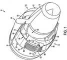
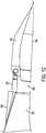
- FIG. 1illustrates an aircraft engine having a trailing edge variable area nozzle assembly according to a first embodiment of the invention.
- FIG. 2is a partially schematic section view of the aircraft engine according to the first embodiment.
- FIG. 3is an end view of the nozzle end of the engine according to the first embodiment.
- FIG. 4is a partially schematic section view of the variable area nozzle assembly portion according to the first embodiment.
- FIG. 5is another partially schematic section view of the variable area nozzle assembly according to the first embodiment.
- FIG. 6is a partially schematic, exploded section view of the variable area nozzle assembly according to the first embodiment.
- FIG. 7is a partially schematic isolated view of a guide structure of the variable area nozzle assembly according to the first embodiment.
- FIG. 8is a partially schematic section view of the variable area nozzle assembly according to the first embodiment.
- FIG. 9Ais a partial exploded view of a variable area nozzle assembly according to a second embodiment of the invention.
- FIG. 9Bis another partial exploded view of the variable area nozzle assembly according to the second embodiment.
- FIG. 10is another partial exploded view of the variable area nozzle assembly according to the second embodiment.
- FIG. 11is another partial exploded view of the variable area nozzle assembly according to the second embodiment.
- FIG. 12is another partial exploded view of the variable area nozzle assembly according to the second embodiment.
- FIG. 13is a partial exploded view of a variable area nozzle assembly according to a third embodiment of the invention.
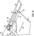
- FIG. 14is an isolated view of a guide structure of the variable area nozzle assembly according to the third embodiment.
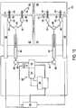
- FIG. 15is schematic illustration of an actuation system for the variable area nozzle assembly according to the third embodiment.
- FIG. 16is an isolated view of a stabilizer of the variable area nozzle assembly according to the third embodiment.
- FIG. 17is a section view of the variable area nozzle assembly according to the third embodiment.
- FIG. 18is another section view of the variable area nozzle assembly according to the third embodiment.
- FIG. 19is another section view of the variable area nozzle assembly according to the third embodiment.
- FIG. 20is another section view of the variable area nozzle assembly according to the third embodiment.
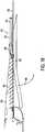
- FIG. 21is a partial exploded view of a variable area nozzle assembly according to a fourth embodiment of the invention.
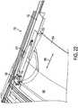
- FIG. 22is an isolated view of a guide structure of the variable area nozzle assembly according to the fourth embodiment.
- FIG. 23is a section view of the variable area nozzle assembly according to the fourth embodiment.
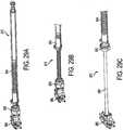
- FIG. 24is another section view of the variable area nozzle assembly according to the fourth embodiment.
- FIG. 25is another section view of the variable area nozzle assembly according to the fourth embodiment.
- FIG. 26is another section view of the variable area nozzle assembly according to the fourth embodiment.
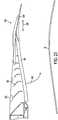
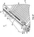
- FIG. 27is a partial exploded view of an actuator for a variable area nozzle assembly according to a fifth embodiment of the invention.
- FIG. 28is schematic illustration of an actuation system for the variable area nozzle assembly according to the fifth embodiment.
- FIGS. 29A-29Cillustrate the actuator according to the fifth embodiment of the invention in various modes of operation.
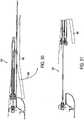
- FIG. 30is a section view of the variable area nozzle assembly according to the fifth embodiment.
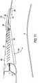
- FIG. 31is another section view of the variable area nozzle assembly according to the fifth embodiment.
- FIGS. 1-8show a variable area nozzle assembly according to a first embodiment of this invention.
- the engine 10includes a trailing edge variable area fan nozzle (VAFN) assembly 12 having a translating ring assembly 50 that may be adjusted, for example, as the engine 10 operates under varying flight conditions. As stated, such an adjustment can cause a shift in the engine's operating line.
- the translating ring assembly 50is translated (i.e., moved fore and aft) to vary the nozzle exit area in order to optimize engine operation and to adjust an amount of engine bypass flow spilled through an upstream exit in the nozzle assembly 12.
- By bleeding or spilling off excess fan flow through the upstream exit of the nozzle assembly 12lower fan pressure ratios for the same amount of delivered mass flow can be obtained, thereby increasing stall margins and avoiding engine malfunction and shutdown.
- variable area fan nozzle assembly 12 of the present inventionis shown in the context of a gas turbine jet aircraft engine.
- the engine 10may be mounted to a wing or fuselage of an aircraft, for example, by a pylon or other, similar support (not illustrated).
- the engine 10includes an engine core 16 and a nacelle 18.
- the engine core 16is housed in a core cowl 19.
- a fan 20is mounted adjacent to an upstream end of the nacelle 18, and includes a series of fan blades 22 that are rotated about the engine centerline C L during engine operation so as to draw a flow of air into an inlet end 26 of the engine 10.
- An annular bypass duct 24is defined between the engine core 16 and the nacelle 18. The air flow drawn into the engine 10 is accelerated by the rotating fan blades 22. A portion of the air flow is directed into and through a compressor (not illustrated) within the engine core 16.
- the air flow through the engine core 16is initially passed through the compressor to increase the air flow pressure, after which the pressurized air is passed through a combustor (not shown), where it is mixed with fuel and ignited.
- the combustion of the fuel and air mixture within the combustorcauses the air to expand which in turn drives a series of turbines at the rear of the engine, indicated generally at 38, to rotate and in turn to provide power to the fan 20.
- bypass flow accelerated by the rotating fan blades 22passes through the bypass duct 24, past stators 40, and out through the nozzle assembly 12.
- the bypass flowprovides the main engine thrust.
- the high pressure heated exhaust gases from the combustion of the fuel and air mixtureare directed through the nozzle assembly 12 out of the rear of the engine core 16.
- the translating ring assembly 50can be a ring-like annular airfoil structure mounted at the trailing end of a thrust reverser 80, adjacent to and circumscribing the engine core cowl 19. The area between the trailing edge of the ring assembly 50 and the core cowl 19 defines the nozzle exit area 52 for the nozzle assembly 12. As shown in FIGS. 1 and 3 , the ring assembly 50 can comprise an arcuate first ring section 54 and an arcuate second ring section 56, each ring section 54, 56 being axially translatable in the direction of the bidirectional arrow 58. Translation of the ring assembly 50 effects a desired size of an upstream exit 60 and varies the outlet geometric and exit area 52 of the nozzle 12 outlet for the engine bypass flow. The ring assembly 50 can be translated, for example, by a plurality of ring actuators 70.
- the thrust reverser 80may be adjacent to and forward of the translating ring assembly 50 to block and redirect the bypass flow in the bypass duct 24 into a thrust reversing vector.
- the thrust reverser 80 and the translating ring assembly 50are in stowed or closed positions.
- the thrust reverser 80can comprise an arcuate first sleeve or cowl section 82 and an opposed arcuate second sleeve or cowl section 84 (shown in FIG. 3 ).
- the thrust reverser sleeve sections 82, 84can be axially translatable in the direction of the bidirectional arrow 86 by a plurality of sleeve actuators 90.
- the thrust reverser sleeve sections 82, 84are translatable over a series of cascade vanes 88.
- the cascade vanes 88are indicated by dashed lead lines in FIG 1 because they are not visible when the thrust reverser 80 is in the stowed position.
- Axial translation of the sleeve sections 82, 84 in the fore and aft directionsallows the bypass air flow to be passed through the cascade vanes 88 to generate a thrust-reversing vector.
- FIG. 3is a partial section view of the aft end of the engine 10, and illustrates the arrangement of the ring and sleeve actuators 70, 90, respectively, around the periphery of the engine 10.
- the sleeve half section 82 and the ring half-section 54cooperate to generally define an approximately 180 degree sector of the combined thrust reverser and translating ring structure.
- sleeve half section 84 and ring half section 56cooperate to generally define an opposed approximately 180 degree sector of the thrust reverser and translating ring structure. Together, these approximate 180 degree sectors cooperate to define the entire approximate 360 degree thrust reverser-translating ring structure.
- each thrust reverser sleeve half-section 82, 84 of the thrust reverser 80can be translatable by one or more (three are shown) peripherally spaced sleeve actuators 90 fixedly mounted in the nacelle 18. In the embodiment shown, three actuators 90 are used for each sleeve half-section 82, 84.
- Each half-section 54, 56 of the translating ring assembly 50similarly can be translated by one or more (three are shown) peripherally spaced ring actuators 70.
- Ring actuators 70can be mounted on an adjacent thrust reverser sleeve section 82, 84, respectively.
- the ring actuators 70could be powered by, for example, electricity, mechanical, pneumatics, hydraulics, or other means, with appropriate power cables and conduits (not shown) passing via pre-defined passages between or above the thrust reverser cascade boxes or pivot doors.
- the number and arrangement of ring and sleeve actuators 70, 90may be varied, for example, according to the thrust reverser and ring assembly configuration, and according to other factors.
- the ring sections 54, 56may be mounted in, for example, upper and lower guide structures 102 located at each end of corresponding sleeve sections 82, 84, respectively.
- FIG. 7is an isolated view of a guide structure 102.
- Guide tubes 104may be mounted in the nacelle 18 and may extend into the ring sections 54, 56 to stabilize the sections 54, 56 against undesirable translation and/or vibration.
- Guide tubesmay alternatively be mounted in the thrust reverser 80.
- the translating ring assembly 50may be a continuous (e.g., one-piece) or, as shown in FIG. 3 , a continuing (e.g., split or multi-section) generally annular ring having an airfoil cross section.
- the upstream exit 60(formed when the ring assembly 50 moves in the aft direction away from the sleeve sections 82, 84 ) therefore can have the form of a generally annular gap extending around the perimeter of the rear of the nacelle 18.
- Other outlet shapescan also be used, e.g., oval, etc.
- the generally annular gap between the ring sections 54, 56 and the sleeve sections 82, 84can be continuous, for example, or interrupted at one or more locations, such as, for example, at points of bifurcation or other separation of the ring assembly 50.
- the bypass duct 24may also be interrupted at one or more locations.
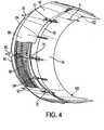
- FIGS. 4-7elements that are obscured or partially obscured due to intervening elements are indicated by dashed lead lines.
- FIG. 4is a partial view of the mounting structure for a first ring section 54 of the translating ring assembly 50 and the corresponding, adjacent first sleeve section 82 of the thrust reverser 80.
- the second ring section 56 of the translating ring assembly 50 and the second sleeve section 84 of the thrust reverser 80which are shown in FIGS. 1 and 3 , can be mounted in a similar manner.
- the thrust reverser 80is in a stowed position, covering the cascade vanes 88.
- the translating ring assembly 50is in an open or deployed position so that an upstream exit 60 is defined between the first ring section 54 and the first sleeve section 84.
- the rearward axial translation of the first ring section 54 to the deployed positionis indicated by the arrow A.
- the ring actuators 70can extend from the sleeve section 82, across the upstream exit 60, and connect to a fore end of the ring section 54.
- the guide tubes 104can also extend from the sleeve section 82, across the upstream exit 60, and connect to the fore end of the ring section 54.
- a sleeve actuation cable 96can connect to each sleeve actuator 90 for power and to provide simultaneous actuation of each actuator 90.
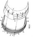
- FIG. 5shows the thrust reverser 80 in a deployed position and the translating ring assembly 50 in the open position.
- the rearward axial translation of the first sleeve section 82 from the position shown in FIG. 4 to the deployed positionis indicated by the arrow B.
- Rearward translation of the sleeve section 82exposes the cascade vanes 88 during operation of the thrust reverser 80.
- the ring section 54can also be translated rearwardly during operation of the thrust reverser 80, as shown in this embodiment. Translation of the ring section 54 at the same time that the thrust reverser 80 is deployed, may be optional because the bypass flow is rerouted through the cascade vanes 88.
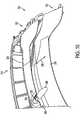
- FIG. 6is a partial, exploded view with the first sleeve section 82 and its corresponding first ring section 54, illustrated separate from the surrounding mounting structure.
- FIG. 7is a partial section isolated view taken through one of the guide structures 102.
- a beam 106can be fixedly attached to a transverse bulkhead 110 that extends 180 degrees and can include axially (e.g., parallel to the centerline of the engine 10 ) extending guide tracks 108 attached thereto.
- the bulkhead 110may be integral with or otherwise fixedly mounted to the engine nacelle 18 ( FIG. 1 ).
- the thrust reverser sleeve section 82can be connected to axially extending track bars 114 ( FIG. 7 ) that are slidably received within the guide tracks 108 of the fixed beam 106.
- the thrust reverser sleeve section 82is thereby slidably mounted with respect to the nacelle 18.
- the thrust reverser sleeve section 82can also include an axially extending track guide 116 in which a translating ring track bar 120 is slidably received.
- the translating ring track bar 120can be connected to the first ring section 54, and the ring section 54 axially translates as the track bar 120 slides within the track guide 116.
- the ring section 54is thereby slidably mounted with respect to the sleeve section 82 of the thrust reverser 80.
- the translating sleeve section 82 and the track bar 120can be powered through conventional means, such as mechanical, electric, hydraulic or pneumatic or other equivalent means.
- FIG. 8illustrates one method of operating the ring section 54 to achieve flow diversion in accordance with this invention.
- the size of the upstream exit 60 and the nozzle exit area 52can be varied in order to achieve differing engine operating parameters.
- the upstream exit 60essentially acts as a "bleed" exit that spills airflow traveling through the bypass duct 24.
- FIG. 8shows a partial section of a downstream portion of the nozzle assembly 12 illustrating a portion of the bypass air flow, indicated by the curved arrows, being bled through the annular upstream exit 60 in one mode of operation of the nozzle assembly 12.
- FIG. 8shows a partial section of a downstream portion of the nozzle assembly 12 illustrating a portion of the bypass air flow, indicated by the curved arrows, being bled through the annular upstream exit 60 in one mode of operation of the nozzle assembly 12.
- the first ring section 54 of the ring 50 and the first sleeve section 82 of the thrust reverser 80are shown in section, along with associated ring and sleeve actuators 70, 90, respectively, used for axial translation of the sections 54, 82.
- the second ring section 56may be similarly constructed and arranged with respect to the second sleeve section 84.
- the thrust reverser 80can include blocker doors 134 that are operatively coupled to the first sleeve section 82 and are pivotable in the direction of the curved arrow 136 thereby to block and redirect the bypass flow into a thrust reversing vector.
- a high pressure seal 130may be disposed between the sections 82, 54, at the trailing edge of the translating sleeve section 82.
- the seal 130can operate to substantially seal any gap between the sections 82, 54 and thereby close the upstream exit 60.
- the ring and sleeve actuators 90, 70can be, for example, mechanical, hydraulic, pneumatic or electric actuators.
- the ring actuator 70is a constant opening air spring damper with hydraulic closing override
- the sleeve actuator 90is an electric actuator.
- FIGS. 9A-12illustrate a variable area nozzle assembly 212 according to a second embodiment of the invention.
- the nozzle assembly 212may be mounted to a nacelle as generally illustrated in FIG. 1 , however with no intervening thrust reverser. Therefore, elements within the embodiment shown in FIG. 9A-12 that are analogous to elements in FIGS. 1-8 use a similar reference numbering system, but are preceded by a " 2 " or " 3. "
- FIGS. 9A and 9Bare partial cutaway illustrations of the variable area nozzle assembly 212 according to the second embodiment of the invention.
- the nozzle assembly 212includes a translating ring assembly (removed for ease of illustration and not shown in FIGS. 9A and 9B ) comprised of two ring sections, of which one ring section 254 is illustrated in FIGS. 9A and 9B .
- the ring section 254is in the closed (i.e., axially fore) position
- FIG. 9Billustrates the ring section 254 in the open or deployed (i.e., axially aft) position.
- the ring section 254can be mounted at the aft end of an engine.
- Peripherally spaced translating ring actuators 270may be mounted to a bulkhead 310 that is fixedly mounted to the nacelle.
- Guide tubes 304may also be fixedly mounted to the bulkhead 310 at one end, and received in the ring section 254 at their opposite ends.
- the translating ring actuators 270can act in unison to translate the ring section 254 in the direction of the bidirectional arrow 258. Referring to FIG. 9B , actuator shafts 272 of the ring actuators 270 can pass through a blister fairing 320 located fore of the ring section 254.
- Upstream fairings 324may be provided at the points where the actuator shafts 272 pass through the blister fairing 320 in order to reduce drag induced by the actuators 270.
- downstream fairings 328may be provided at the points where the actuator shafts 272 are received in the ring section 254.
- each end of the blister fairing 320can include an upstream portion 332 of a beaver tail split fairing 330, and a downstream portion 334 of the fairing 330 can be connected to and translatable with the translating ring section 254. Translation of the translating ring section 254 in the direction of the bidirectional arrow 258 can create an upstream exit 260 between the translating ring section 254 and the blister fairing 320.
- the aft edge of the blister fairing 320can include a bullnose section 255 ( FIG.
- FIG. 12is a partial, isolated view of the upstream and downstream fairings 324, 328 of the beaver tail split fairing 330.
- fairings 320, 324, 328, 330 of the aforesaid described embodimentcan by selectively used in conjunction with other embodiments described herein.
- fairings analogous to fairings 324, 328could be used in conjunction with the translating sleeve actuators 90, spaced ring actuators 70, or other actuators disclosed herein.
- FIGS. 13-20illustrate a variable area nozzle assembly 412 according to a third embodiment of the invention.
- the nozzle assembly 412includes a translating ring assembly 450 and may be mounted to a nacelle 18 as generally illustrated in FIG. 1 .
- the translating ring assembly 450 according to the third embodimentcan be comprised of two ring sections, of which a first ring section 454 is illustrated in FIG. 13 .
- the second ring section 456, illustrated schematically in FIG. 15may be a mirror image of the ring section 454.
- the translating ring section 454is in the closed or non-deployed position, with no upstream exit defined between the ring section 454 and the thrust reverser sleeve section 482.
- the translating ring assembly 450is mounted aft of a thrust reverser 460 comprising two translating sleeve sections, of which a first sleeve section 462 is illustrated in FIG. 13 .
- the first sleeve section 462 of the thrust reverser 460can be translated by one or more actuators 464.
- the ring section 454can be operated by an actuation system including ring actuators 470 located at each end of the first translating ring section 454.
- Stabilizer assemblies 480 connecting the first ring section 454 to the first sleeve section 462can be spaced along the periphery of the nozzle assembly 412 to reduce undesirable translation and/or vibration (e.g., flutter) of the ring section 454.
- Analogous stabilizer assembliescan be added to other embodiments shown herein where additional stabilization is desired.
- a motor or drive mechanism 482governs the motion of the ring actuators 470.
- the drive mechanism 482is connected to a splined coupling 484 by transmission shafting 485 and a gear box 486.
- the splined coupling 484terminates at the aft end of the sleeve section 462 at a gear box 488, which is coupled to flexible cable shafting 490.
- the flexible shafting 490is connected to the actuators 470 at each end of the translating ring section 454.
- the drive mechanism 482is thereby coupled to the ring actuators 470 to effect translation of the ring section 454.
- the translating ring section 454may be mounted in, for example, upper and lower guide structures 500 located at each end of the ring section 454. Each translating ring actuator 470 can be operably coupled with a guide structure 500, as discussed below with reference to FIG. 14 .
- FIG. 14is a partial view of a guide 500 and associated actuator 470 at one end of the ring section 454.
- the thrust reverser sleeve section 462 forward of the ring section 454can be connected to an axially extending beam 502 of the guide 500.
- the ring section 454is mounted to a track bar 503 that is slidably mounted on the beam 502.
- the ring section 454is thereby slidably mounted with respect to the sleeve section 462.
- the guide 500includes a slider 504 that receives a screw shaft 506.
- the screw shaft 506can be coupled to a gear box 508 that converts rotary movement of the flexible actuator cable 490 to rotary movement of the screw shaft 506.
- Rotation of the screw shaft 506 within the slider 504translates the track 503 along the beam 502, which can be used to effect translation of the ring section 454 in the direction of the bidirectional arrow 458.
- the aforesaid described actuator systemcould be used in each of the actuator embodiments discussed elsewhere herein.
- FIG. 15is a schematic view of an actuation and control system that may be used to actuate translation of the translating ring assembly 450 illustrated in FIGS. 13 and 14 .
- the drive unit 482can include a motor 516 coupled to a gear box 520. Rotational motion provided by the motor 516 is sequentially transmitted through the gear box 520, the transmission shafting 485, the gear boxes 486, the splined couplings 484, the actuator cable 490, and ultimately to the ring actuators 470 through the gear boxes 488 to provide axial translation of the ring sections 454, 456.
- the motor 516can be coupled to a host controller unit 526, which is coupled to a full authority digital engine controller (FADEC) 540.
- the FADEC 540can thereby control actuation of the ring sections 454, 456 of the translating ring assembly 450.
- the FADEC 540can also control actuation of a thrust reverser.
- Linear variable differential transformers 550can be coupled to the ring sections 454, 456 to provide position feedback to the FADEC 540.
- FIG. 16is an isolated view of a stabilizer assembly 480.
- the stabilizer assembly 480can include an aft portion 580 fixedly mounted to the translating ring section 454, and a guide portion 582 fixed to the translating sleeve 482 of the thrust reverser 480.
- the aft portion 580can be axially slidable within the guide portion 582 with relatively low clearance to minimize unwanted translation and/or vibration (e.g., flutter) of the ring section 454.
- FIG. 17is a sectional partial view of a downstream portion of the nozzle assembly 412, taken along a longitudinal section that passes through a stabilizer assembly 480.
- the translating ring section 454 in FIG. 17is translatable in the direction of the bidirectional arrow 458 to create an upstream exit forward of the section 454, as discussed above with reference to the embodiment illustrated in FIG. 8 .
- Blocker doors 586are operatively coupled to the first sleeve section 462 and pivotable in the direction of the curved arrow 588 thereby to block and redirect the bypass flow through cascade vanes 590 to produce a thrust reversing vector.
- FIG. 18is a sectional partial view of a downstream portion of the nozzle assembly 412, taken along a longitudinal section that passes through a translating ring actuator 470 at one end of the translating ring section 454.
- FIG. 19is a sectional partial view of a downstream portion of the nozzle assembly 412, taken along a longitudinal section that passes through an actuator 464 of the thrust reverser 460.
- FIG. 20is a sectional partial view of a downstream portion of the nozzle assembly 412, taken along a longitudinal section that passes through a splined coupling 484.
- FIGS. 21-26illustrate a variable area nozzle assembly 612 according to a fourth embodiment of the invention.
- the nozzle assembly 612may be mounted to a nacelle as generally illustrated in FIG. 1 .
- FIG. 21is a partially exploded, cutaway illustration of the variable area nozzle assembly 612, which has a translating ring assembly 650 at an aft end of the nozzle assembly.
- FIG. 22is an isolated view of an actuator of the translating ring assembly 650. Translation of the translating ring assembly 650 can be effected by an actuation system such as, for example, the actuation system illustrated in FIG. 15 .
- the translating ring assembly 650can be comprised of two ring sections, of which a first ring section 654 is illustrated in FIG. 21 .
- the second ring section(not illustrated) may be a mirror image of the ring section 654.
- the first translating ring section 654is in the closed position, with no upstream exit defined forward of the first section 654.
- the ring assembly 650is mounted aft of a thrust reverser 660 comprising two translating sleeve sections, of which a first sleeve section 662 is illustrated in FIG. 21 .
- the translating sleeve section 662 of the thrust reverser 660can be translated by one or more actuators 664.
- the ring section 654can be operated by an actuation system including actuators 670 located at each end of the ring section 654.
- Stabilizer assemblies 680 connecting the ring section 654 to the sleeve section 662can be spaced along the periphery of the nozzle assembly 612 to reduce undesirable translation and/or vibration (e.g., flutter) of the ring section 654.
- a motor or drive mechanism 682governs the motion of the ring actuators 670.
- the drive mechanism 682is connected to a splined coupling 684 by transmission shafting 685 and a gear box 686.
- the splined coupling 684terminates at the aft end of the sleeve section 662 at a gear box 688, which is coupled to flexible cable shafting 690.
- the flexible cable shafting 690is connected to the ring actuators 670 at each end of the translating ring section 654.
- the drive mechanism 682is thereby coupled to the ring actuators 670 to effect translation of the ring section 654.
- the ring section 654may be translatably mounted in, for example, upper and lower guide structures 700 located at each end of the ring section 654.
- Each actuator 670can be operably coupled with a guide structure 700 , as discussed below with reference to FIG. 22 .
- FIG. 22is a partial view of a guide 700 and associated actuator 670 at one end of the ring section 654.
- the translating sleeve section 662 forward of the ring section 654can be connected to an axially extending beam 702 of the guide 700.
- the ring section 654is mounted to a track bar 703 that is slidably mounted on the beam 702.
- the first translating ring section 654is thereby slidably mounted with respect to the first thrust reverser sleeve section 662.
- the ring actuator 670is coupled at one end to a gear box 708 and at its opposite end to the track bar 703.
- the gear box 708utilizes rotational motion of the flexible cable 690 to cause the actuator 670 to translate the ring section 654 in the direction of the bidirectional arrow 658.
- FIG. 23is a sectional partial view of a downstream portion of the nozzle assembly 612, taken along a longitudinal section that passes through one of the stabilizer assemblies 680.
- the translating ring section 654 illustrated in FIG. 23is translatable in the direction of the bidirectional arrow 658 to create an upstream exit forward of the section 654, as discussed above with reference to the embodiment illustrated in FIG. 8 .
- the thrust reverser 660can include blocker doors 786 that are operatively coupled to the first sleeve section 662 and are pivotable in the direction of the curved arrow 788 thereby to block and redirect the bypass flow through variable depth cascade vanes 790 to produce a thrust reversing vector.
- FIG. 24is a sectional partial view of a downstream portion of the nozzle assembly 612, taken along a longitudinal section that passes through an actuator 670 at one end of the translating ring section 654.
- FIG. 25is a sectional partial view of a downstream portion of the nozzle assembly 612, taken along a longitudinal section that passes through an actuator 664 of the thrust reverser 660.
- FIG. 26is a sectional partial view of a downstream portion of the nozzle assembly 612, taken along a longitudinal section that passes through a splined coupling 684.
- FIGS. 27-31illustrate an actuator 870 for translating ring sections 854, 856 of a translating ring assembly 650 (illustrated schematically in FIG. 28 ) according to a fifth embodiment of the invention.
- Each translating ring section 854, 856can include an actuator 870 at each end of the ring section.
- an actuator 870is shown in a cutaway section of a portion of a variable area nozzle assembly 812.
- the variable area nozzle assembly 812includes a thrust reverser 860 located forward of the translating ring assembly 650.
- the movable cowl or sleeve of the thrust reverser 860is present but not shown in FIG. 27 for ease of illustration so that that cascade vanes 990 of the thrust reverser are visible.
- the translating ring assembly 650 and thrust reverser 860 of the nozzle assembly 812can be, for example, generally similar in structure to those of the variable area nozzle assemblies 412, 612 discussed above.
- the thrust reverser 860is in the stowed or non-deployed position.
- the translating ring actuator 870can include a bearing 886 that can be fixedly mounted forward of the thrust reverser 860.
- the bearing 886is coupled to an extensible shaft 888.
- the shaft 888is coupled to a spline bush gimbal 890, which is coupled to a sliding spline 894.
- the sliding spline 894is fixed to a track bar 903, which can be fixed to one end of the translating ring section 854 ( FIG. 28 ).
- the track bar 903is slidably mounted on a beam 702 that is fixed to a section of the thrust reverser 860.
- the first translating ring section 854is thereby slidably mounted with respect to the thrust reverser 860.
- the bearing 886 at each end of the translating ring section 854is coupled to transmission shafting 885. Rotation of the transmission shafting 885 effects translation of the ring section 854.
- FIG. 28is a schematic view of an actuation and control system that may be used with the translating ring assembly 850.
- a drive unit 882can include a motor 916 coupled to a gear box 920. Rotation provided by the motor 916 is transmitted through the gear box 920 to the transmission shafting 885. The rotational motion from the transmission shafting 885 is utilized by the actuators 870 at each end of the ring sections 854, 856 to translate the ring sections.
- the motor 916can be coupled to a host controller unit 926, which is coupled to a full authority digital engine controller (FADEC) 940.
- the FADEC 940can thereby control actuation of the translating ring sections 854, 856 of the translating ring assembly 850.
- the FADEC 940can also control actuation of a thrust reverser.
- Linear variable differential transformers 950can be coupled to the ring sections 854, 856 to provide position feedback information to the FADEC 940.
- FIGS. 29A-29Cillustrate an actuator 870 in three operational modes.
- the actuator 890is fully retracted, corresponding to an operating condition in which the translating ring assembly 850 and the thrust reverser 860 are stowed.
- FIG. 29Bthe actuator 890 is in a deployed state in which the translating ring assembly 850 is deployed and the thrust reverser 860 is stowed.
- FIG. 29Cillustrates the actuator 890 where the thrust reverser 860 is deployed.
- FIG. 30is a sectional partial view of a downstream portion of the nozzle assembly 812, taken along a longitudinal section that passes through an actuator 870 at one end of the translating ring section 854.
- the translating ring section 854is in a stowed position in FIG. 30 .
- FIG. 31is a partial view of a downstream portion of the nozzle assembly 812, taken along a longitudinal section that passes through an actuator 870 at one end of the translating ring section 854.
- the translating ring section 854is in a deployed position in FIG. 31 .
Landscapes
- Engineering & Computer Science (AREA)
- Chemical & Material Sciences (AREA)
- Combustion & Propulsion (AREA)
- Mechanical Engineering (AREA)
- General Engineering & Computer Science (AREA)
- Structures Of Non-Positive Displacement Pumps (AREA)
- Control Of Turbines (AREA)
- Turbine Rotor Nozzle Sealing (AREA)
Abstract
Description
- The present invention generally relates to gas turbine aircraft engines, and in particular, to a translating trailing edge variable area nozzle assembly for a gas turbine aircraft engine for controlling the air flow exhausted from the engine for varying performance output.
- Typical aircraft turbofan jet engines include a fan that draws and directs a flow of air into and around an engine core and a nacelle. The nacelle surrounds the engine core and helps promote the laminar flow of air past the engine core. The flow of air that is directed into the engine core is initially passed through a compressor that increases the air flow pressure, and then through a combustor where the air is mixed with fuel and ignited. The combustion of the fuel and air mixture causes a series of turbine blades at the rear of the engine core to rotate, and in turn to provide power to the fan. The high-pressure heated exhaust gases from the combustion of the fuel and air mixture are thereafter directed through an exhaust nozzle out of the rear of the engine.
- The flow of air that is directed around the engine core is called bypass flow and provides the main thrust for the aircraft.
EP 0 315 524 A1 discloses to use the bypass flow also to help slow an aircraft, when the flow is diverted by thrust reversers mounted in the nacelle structure that surrounds the engine core. The bypass flow may or may not be mixed with the engine core exhaust before exiting. - Several turbofan engine parameters are important to those of skill in the art in order to optimize design characteristics and performance. The bypass ratio (BPR) is the ratio of air mass passing through the fan to that going through the core. Higher BPR engines can be more efficient and quieter. In general, a higher BPR results in lower average exhaust velocities and less jet noise at equivalent thrust rating of a lower BPR engine. Also, the exit area and mass flow rates and pressures define the fan pressure ratio (FPR).
- Turbofan engine operation parameters and characteristics can further be reflected in a turbofan engine's operating map. Operation maps can be created in various ways, such as on turbine rig test results or predicted by applicable computer programs as is known in the art. Typical turbine operation maps can show relationships between pressure ratios (e.g., FPR) on the y-axis and corrected mass flows on the x-axis. The operation line(s) on the turbofan operation map reflects the line or ranges in which the relationship between FPRs and correct mass flow values result in maximum thrust and minimum fuel consumption. For example, it is known that altering the engine's characteristics that lower the operating line can increase fuel efficiency and reduce noise emissions from the engine since more thrust is produced with less fuel being injected into the combustors, and the stoichiometry of the engine is increased. The resulting reduction of FPRs, however, can reach a practical limit as a low FPR can cause engine fan stall, blade flutter or compressor surge under certain operating conditions, with insufficient bypass flow possibly causing engine malfunction.
- A solution to optimizing the operating line at all flight conditions, for those engines that draw significant benefit from such an optimization, includes varying the exit nozzle area during operation. From
US3,820,719 andEP 0 315 524 A1 , a fan type gas turbine engine for use in an aircraft is known, which has a fan cowl comprising at least two annular parts, one part being axially separable from the remainder of the fan cowl to provide an annular opening giving additional nozzle area during take-off conditions. - Accordingly, it can be seen that a need exists for a variable area nozzle assembly for an aircraft turbine engine that promotes a cost effective, simple and efficient operation for control of engine output to match desired flight conditions.
- According to one embodiment of the invention, the exit area of a nozzle assembly is varied by translating, or moving fore and aft, a ring assembly located at the rear of the engine nacelle. The ring may be axially translatable, for example, along the axis of the engine. As the ring translates, the trailing edge of the ring defines a variable nozzle exit area. Translation of the ring creates an upstream exit at a leading edge of the ring assembly to bleed or otherwise spill excess flow from the engine bypass duct. As the engine operates in various flight conditions, the ring can be translated to optimize on-demand the engine operating line, resulting in lower fan pressure ratios and thereby increase the efficiency of the engine.
- According to one embodiment of the invention, a nacelle for a turbofan engine comprises a stationary forward nacelle portion; a thrust reverser comprising an array of cascade vanes disposed aft of the forward nacelle portion, a thrust reverser sleeve disposed aft of the forward nacelle portion, the thrust reverser sleeve being selectively movable between a stowed position and a deployed position, wherein in the stowed position the thrust reverser sleeve substantially covers the cascade vanes, and in the deployed position, at least a portion of the cascade vanes are not covered by the thrust reverser sleeve, and a plurality of thrust reverser sleeve actuators configured to selectively move the thrust reverser sleeve between the stowed position and the deployed position; a fan nozzle sleeve disposed aft of the thrust reverser sleeve and being selectively movable between a forward position and one or more extended positions, wherein an upstream bypass flow exit is formed between the fan nozzle sleeve and the thrust reverser sleeve when the fan nozzle sleeve is in the extended position; and, a plurality of fan nozzle sleeve actuators extending from the stationary forward nacelle portion to the fan nozzle sleeve are configured to selectively move the fan nozzle sleeve between the forward position and the extended position, the fan nozzle sleeve actuators being separate from and spaced apart from the thrust reverser sleeve actuators.
- According to one embodiment of the invention, the fan nozzle sleeve comprises a first fan nozzle sleeve segment disposed on a first side of the engine, and a second fan nozzle sleeve segment disposed on an opposed second side of the engine.
- According to one embodiment of the invention, the nacelle comprises a transverse bulkhead on the forward nacelle portion, wherein the thrust reverser sleeve and the fan nozzle sleeve are movably connected to the transverse bulkhead.
- One embodiment of the invention relates to a nacelle for a turbofan aircraft engine comprising: a stationary forward nacelle portion having an inlet end and an opposed rear end; a thrust reverser comprising: a cascade array disposed aft of the rear end of the stationary forward nacelle portion, a translating thrust reverser sleeve having a front edge and a trailing edge, the thrust reverser sleeve being movably disposed aft of the rear end of the stationary forward nacelle portion, the thrust reverser sleeve being movable between a stowed position in which the front edge is proximate to the rear end of the stationary forward nacelle portion and the thrust reverser sleeve substantially covers the cascade array, and a deployed position in which the thrust reverser sleeve is disposed substantially aft of the cascade array and the cascade array is substantially uncovered, and at least one thrust reverser actuator extending from the stationary forward nacelle portion to the thrust reverser sleeve, and being operable to selectively move the thrust reverser sleeve between the stowed position and the deployed position; a translating fan nozzle sleeve having a forward edge, the fan nozzle sleeve being movably disposed aft of the translating thrust reverser sleeve, the fan nozzle sleeve being movable between a forward position in which the forward edge is proximate to the trailing edge of the thrust reverser sleeve, and an extended position in which an upstream bypass flow exit is disposed between the forward edge of the fan nozzle sleeve and the trailing edge of the thrust reverser sleeve; and at least one fan nozzle actuator separate from and spaced apart from the thrust reverser actuator, the fan nozzle actuator being configured to selectively move the fan nozzle sleeve between the forward position and the extended position.
- One embodiment of the invention relates to a nacelle wherein the translating thrust reverser sleeve comprises a first arcuate thrust reverser sleeve portion and a second arcuate thrust reverser sleeve portion, wherein at least one thrust reverser actuator is operable to selectively move the first thrust reverser sleeve portion between the stowed position and the deployed position, and wherein at least one thrust reverser actuator is operable to selectively move the second thrust reverser sleeve portion between the stowed position and the deployed position.
- One embodiment of the invention relates to a nacelle wherein the translating fan nozzle sleeve comprises a first arcuate fan nozzle sleeve portion having a first end and a second end, and a second arcuate fan nozzle sleeve portion having a third end and a fourth end, wherein at least one fan nozzle actuator is operable to selectively move the first fan nozzle sleeve portion between the forward position and the extended position, and wherein at least one fan nozzle actuator is operable to selectively move the second thrust reverser sleeve portion between the forward position and the extended position.
- One embodiment of the invention relates to a nacelle which comprises further a transverse bulkhead, wherein the first end of the first arcuate fan nozzle sleeve portion and the third end of the second arcuate fan nozzle sleeve portion are slidably connected an upper portion of the transverse bulkhead, and wherein the second end of the first arcuate fan nozzle sleeve portion and the fourth end of the second arcuate fan nozzle sleeve portion are slidably connected to a lower portion of the transverse bulkhead.
- One embodiment of the invention relates to a nacelle wherein each of the first, second, third and fourth ends of the respective first and second fan nozzle sleeve portions is movably connected to the transverse bulkhead by a guide mechanism comprising: a beam attached to and rearwardly extending from the transverse bulkhead; a first guide track attached to the beam; a first track bar attached to the thrust reverser sleeve and slidably engaged with the first guide track; at least a second guide track attached to the thrust reverser sleeve; and a second track bar slidably engaged with the second guide track, the second track bar being connected to an end of a respective fan nozzle sleeve portion.
- One embodiment of the invention relates to a nacelle wherein sliding movement of the first or second track bars is powered by at least one mechanical, electrical, hydraulic or pneumatic device.
- One embodiment of the invention relates to a nacelle which comprises a plurality of spaced extendable guide tubes axially extending between the thrust reverser sleeve and the fan nozzle sleeve, the guide tubes being configured to permit longitudinal translating movement of the fan nozzle sleeve, and to inhibit movement of the fan nozzle sleeve in directions that are transverse to the direction of the longitudinal translating movement of the fan nozzle sleeve.
- One embodiment of the invention relates to a nacelle wherein the fan nozzle actuator is operable to move the fan nozzle sleeve such that the forward edge of the fan nozzle sleeve is a selected distance from the trailing edge of the thrust reverser sleeve when the fan nozzle sleeve is in the extended position, whereby a width of the upstream bypass flow exit can be selectively varied.
- One embodiment of the invention relates to a nacelle comprising a seal disposed between the forward edge of the fan nozzle sleeve and the trailing edge of the thrust reverser sleeve, the seal being configured to substantially block airflow between the forward edge of the fan nozzle sleeve and the trailing edge of the thrust reverser sleeve when the fan nozzle sleeve is in the forward position.
- One embodiment of the invention relates to a nacelle for a turbofan aircraft engine, the nacelle comprising: a stationary forward nacelle portion having an inlet end and an opposed aft end; a translating fan nozzle sleeve having a forward edge, the fan nozzle sleeve being movably disposed aft of the forward nacelle portion, the fan nozzle sleeve being movable between a forward position, in which the forward edge is proximate to the aft end of the forward nacelle portion with no cascade-type thrust reverser disposed therebetween, and one or more extended positions in which an upstream bypass flow exit is disposed between the forward edge of the fan nozzle sleeve and the aft end of the forward nacelle portion; and at least one fan nozzle actuator extending from the stationary forward nacelle portion to the fan nozzle sleeve, the fan nozzle actuator being operable to selectively move the fan nozzle sleeve between the forward position and the extended position.
- One embodiment of the invention relates to a nacelle further comprising a plurality of spaced extendable guide tubes axially extending between the forward nacelle portion and the fan nozzle sleeve, the guide tubes being configured to permit longitudinal translating movement of the fan nozzle sleeve, and to inhibit movement of the fan nozzle sleeve in directions that are transverse to the direction of the longitudinal translating movement of the fan nozzle sleeve.
- One embodiment of the invention relates to a nacelle wherein the fan nozzle actuator is operable to move the fan nozzle sleeve such that the forward edge of the fan nozzle sleeve is a selected distance from the trailing edge of the forward nacelle portion when the fan nozzle sleeve is in the extended position, thereby permitting a width of the upstream bypass flow exit to be selectively varied.
- One embodiment of the invention relates to a nacelle further comprising a blister fairing extending along the aft end of the forward nacelle portion, the blister fairing at least partially overlapping the forward edge of the translating fan nozzle sleeve when the fan nozzle sleeve is in the forward position.
- One embodiment of the invention relates to a nacelle wherein a portion of the fan nozzle actuator extends through an actuator opening in the blister fairing to the fan nozzle sleeve, and further comprising an upstream fairing on the blister fairing at least partially shrouding the actuator opening, and a downstream fairing at least partially shrouding the portion of the fan nozzle actuator.
- One embodiment of the invention relates to a nacelle wherein an upstream portion of a split beavertail fairing on the forward stationary nacelle portion at least partially shrouds a forward portion of a beam rearwardly extending from the transverse bulkhead, and wherein a downstream portion of the split beavertail fairing on the fan nozzle sleeve at least partially shrouds an aft portion of the beam, wherein the upstream and downstream portions of the split beavertail fairing combine to form a substantially continuous contoured external surface when the translating fan nozzle sleeve is in the forward position.
- One embodiment of the invention relates to a nacelle for a turbofan aircraft engine comprising: a stationary forward nacelle portion having an inlet end and an opposed rear end; a thrust reverser comprising: a cascade array disposed aft of the rear end of the stationary forward nacelle portion; a translating thrust reverser sleeve comprising first and second thrust reverser sleeve segments each having a front edge and a trailing edge, the thrust reverser sleeve segments being movably disposed aft of the rear end of the stationary forward nacelle portion, each thrust reverser sleeve segment being movable between a stowed position in which its front edge is proximate to the rear end of the stationary forward nacelle portion and the thrust reverser sleeve segment substantially covers a portion of the cascade array, and a deployed position in which the thrust reverser sleeve segment is disposed substantially aft of the cascade array and does not cover a substantial portion of the cascade array; and plurality of thrust reverser actuators operable to selectively move the thrust reverser sleeve segments between their stowed positions and their deployed positions; translating fan nozzle sleeve comprising first and second fan nozzle sleeve segments each having a forward edge, an upper end and a lower end, and being movably disposed aft of the translating thrust reverser sleeve, each fan nozzle sleeve segment being movable between a forward position in which the forward edge is proximate to the trailing edge of one of the thrust reverser sleeve segments, and an extended position in which an upstream bypass flow exit is disposed between the forward edge of the fan nozzle sleeve segment and the trailing edge of one of the thrust reverser sleeve segments; and a plurality of fan nozzle sleeve actuators that are separate from the thrust reverser actuators, at least one fan nozzle actuator being located proximate to the upper end of each fan nozzle sleeve segment and at least one other fan nozzle actuator being located proximate to the lower end of each fan nozzle sleeve segment, the fan nozzle actuators being operable to selectively move the fan nozzle sleeve segments between their forward position and their extended position.
- One embodiment of the invention relates to a nacelle wherein the fan nozzle actuators extend from the thrust reverser sleeve to the fan nozzle sleeve.
- One embodiment of the invention relates to a nacelle wherein the fan nozzle actuators extend from the forward nacelle portion to the fan nozzle sleeve.
- One embodiment of the invention relates to a nacelle further comprising at least a first stabilizer disposed between the first thrust reverser sleeve segment and the first fan nozzle sleeve segment, and at least a second stabilizer disposed between the second thrust reverser sleeve segment and the second fan nozzle sleeve segment, the first and second stabilizers being configured to permit translational movement between the thrust reverser sleeve segments and the fan nozzle sleeve segments, and to substantially inhibit movement of the first and second fan nozzle sleeve segments in a direction that is non-parallel to the translational movement between the thrust reverser sleeve segments and the fan nozzle sleeve segments.
- One embodiment of the invention relates to a nacelle comprising an upper guide structure slidably supporting the upper ends of the first and second fan nozzle sleeve segments, and a lower guide structure slidably supporting the lower ends of the first and second fan nozzle sleeve segments. One embodiment of the invention relates to a nacelle wherein the upper and lower guide structures each comprise a beam that extends aft of the first and second translating thrust reverser sleeves, and a track bar connected to one of the first and second fan nozzle sleeve segments, the track bar being slidably engaged with the beam.
- One embodiment of the invention relates to a nacelle further comprising a slider attached to the track bar, and a screw shaft engaged with the slider and extending between the slider and an actuator gear box.
- The foregoing and other features, aspects, and advantages of the invention will become more apparent upon review of the detailed description of the preferred embodiments set forth below when taken in conjunction with the accompanying drawing figures, which are briefly described as follows.
- According to common practice, the various features of the drawings discussed below are not necessarily drawn to scale. Dimensions of various features and elements in the drawings may be expanded or reduced to more clearly illustrate the embodiments of the invention.
FIG. 1 illustrates an aircraft engine having a trailing edge variable area nozzle assembly according to a first embodiment of the invention.FIG. 2 is a partially schematic section view of the aircraft engine according to the first embodiment.FIG. 3 is an end view of the nozzle end of the engine according to the first embodiment.FIG. 4 is a partially schematic section view of the variable area nozzle assembly portion according to the first embodiment.FIG. 5 is another partially schematic section view of the variable area nozzle assembly according to the first embodiment.FIG. 6 is a partially schematic, exploded section view of the variable area nozzle assembly according to the first embodiment.FIG. 7 is a partially schematic isolated view of a guide structure of the variable area nozzle assembly according to the first embodiment.FIG. 8 is a partially schematic section view of the variable area nozzle assembly according to the first embodiment.FIG. 9A is a partial exploded view of a variable area nozzle assembly according to a second embodiment of the invention.FIG. 9B is another partial exploded view of the variable area nozzle assembly according to the second embodiment.FIG. 10 is another partial exploded view of the variable area nozzle assembly according to the second embodiment.FIG. 11 is another partial exploded view of the variable area nozzle assembly according to the second embodiment.FIG. 12 is another partial exploded view of the variable area nozzle assembly according to the second embodiment.FIG. 13 is a partial exploded view of a variable area nozzle assembly according to a third embodiment of the invention.FIG. 14 is an isolated view of a guide structure of the variable area nozzle assembly according to the third embodiment.FIG. 15 is schematic illustration of an actuation system for the variable area nozzle assembly according to the third embodiment.FIG. 16 is an isolated view of a stabilizer of the variable area nozzle assembly according to the third embodiment.FIG. 17 is a section view of the variable area nozzle assembly according to the third embodiment.FIG. 18 is another section view of the variable area nozzle assembly according to the third embodiment.FIG. 19 is another section view of the variable area nozzle assembly according to the third embodiment.FIG. 20 is another section view of the variable area nozzle assembly according to the third embodiment.FIG. 21 is a partial exploded view of a variable area nozzle assembly according to a fourth embodiment of the invention.FIG. 22 is an isolated view of a guide structure of the variable area nozzle assembly according to the fourth embodiment.FIG. 23 is a section view of the variable area nozzle assembly according to the fourth embodiment.FIG. 24 is another section view of the variable area nozzle assembly according to the fourth embodiment.FIG. 25 is another section view of the variable area nozzle assembly according to the fourth embodiment.FIG. 26 is another section view of the variable area nozzle assembly according to the fourth embodiment.FIG. 27 is a partial exploded view of an actuator for a variable area nozzle assembly according to a fifth embodiment of the invention.FIG. 28 is schematic illustration of an actuation system for the variable area nozzle assembly according to the fifth embodiment.FIGS. 29A-29C illustrate the actuator according to the fifth embodiment of the invention in various modes of operation.FIG. 30 is a section view of the variable area nozzle assembly according to the fifth embodiment.FIG. 31 is another section view of the variable area nozzle assembly according to the fifth embodiment.FIGS. 1-8 show a variable area nozzle assembly according to a first embodiment of this invention.- Referring to
FIGS. 1 and2 , theengine 10 includes a trailing edge variable area fan nozzle (VAFN)assembly 12 having a translatingring assembly 50 that may be adjusted, for example, as theengine 10 operates under varying flight conditions. As stated, such an adjustment can cause a shift in the engine's operating line. The translatingring assembly 50 is translated (i.e., moved fore and aft) to vary the nozzle exit area in order to optimize engine operation and to adjust an amount of engine bypass flow spilled through an upstream exit in thenozzle assembly 12. By bleeding or spilling off excess fan flow through the upstream exit of thenozzle assembly 12, lower fan pressure ratios for the same amount of delivered mass flow can be obtained, thereby increasing stall margins and avoiding engine malfunction and shutdown. For the purposes of illustration, the exemplary variable areafan nozzle assembly 12 of the present invention is shown in the context of a gas turbine jet aircraft engine. Theengine 10 may be mounted to a wing or fuselage of an aircraft, for example, by a pylon or other, similar support (not illustrated). - The
engine 10 includes anengine core 16 and anacelle 18. Theengine core 16 is housed in acore cowl 19. As shown inFIG. 2 , afan 20 is mounted adjacent to an upstream end of thenacelle 18, and includes a series offan blades 22 that are rotated about the engine centerlineCL during engine operation so as to draw a flow of air into aninlet end 26 of theengine 10. Anannular bypass duct 24 is defined between theengine core 16 and thenacelle 18. The air flow drawn into theengine 10 is accelerated by the rotatingfan blades 22. A portion of the air flow is directed into and through a compressor (not illustrated) within theengine core 16. The air flow through theengine core 16 is initially passed through the compressor to increase the air flow pressure, after which the pressurized air is passed through a combustor (not shown), where it is mixed with fuel and ignited. The combustion of the fuel and air mixture within the combustor causes the air to expand which in turn drives a series of turbines at the rear of the engine, indicated generally at38, to rotate and in turn to provide power to thefan 20. - The bypass flow accelerated by the rotating
fan blades 22 passes through thebypass duct 24,past stators 40, and out through thenozzle assembly 12. The bypass flow provides the main engine thrust. The high pressure heated exhaust gases from the combustion of the fuel and air mixture are directed through thenozzle assembly 12 out of the rear of theengine core 16. - The translating
ring assembly 50 can be a ring-like annular airfoil structure mounted at the trailing end of athrust reverser 80, adjacent to and circumscribing theengine core cowl 19. The area between the trailing edge of thering assembly 50 and thecore cowl 19 defines thenozzle exit area 52 for thenozzle assembly 12. As shown inFIGS. 1 and3 , thering assembly 50 can comprise an arcuatefirst ring section 54 and an arcuatesecond ring section 56, eachring section bidirectional arrow 58. Translation of thering assembly 50 effects a desired size of anupstream exit 60 and varies the outlet geometric andexit area 52 of thenozzle 12 outlet for the engine bypass flow. Thering assembly 50 can be translated, for example, by a plurality ofring actuators 70. - The
thrust reverser 80 may be adjacent to and forward of the translatingring assembly 50 to block and redirect the bypass flow in thebypass duct 24 into a thrust reversing vector. InFIG. 1 , thethrust reverser 80 and the translatingring assembly 50 are in stowed or closed positions. Thethrust reverser 80 can comprise an arcuate first sleeve orcowl section 82 and an opposed arcuate second sleeve or cowl section84 (shown inFIG. 3 ). The thrustreverser sleeve sections bidirectional arrow 86 by a plurality ofsleeve actuators 90. The thrustreverser sleeve sections FIG 1 because they are not visible when thethrust reverser 80 is in the stowed position. Axial translation of thesleeve sections cascade vanes 88 to generate a thrust-reversing vector. FIG. 3 is a partial section view of the aft end of theengine 10, and illustrates the arrangement of the ring andsleeve actuators engine 10. As shown inFIG. 1 , and more clearly inFIG. 3 , thesleeve half section 82 and the ring half-section 54 cooperate to generally define an approximately 180 degree sector of the combined thrust reverser and translating ring structure. Likewise,sleeve half section 84 andring half section 56 cooperate to generally define an opposed approximately 180 degree sector of the thrust reverser and translating ring structure. Together, these approximate 180 degree sectors cooperate to define the entire approximate 360 degree thrust reverser-translating ring structure.- In the embodiment shown in
FIGS. 1-3 , each thrust reverser sleeve half-section thrust reverser 80 can be translatable by one or more (three are shown) peripherally spacedsleeve actuators 90 fixedly mounted in thenacelle 18. In the embodiment shown, threeactuators 90 are used for each sleeve half-section section ring assembly 50 similarly can be translated by one or more (three are shown) peripherally spacedring actuators 70.Ring actuators 70 can be mounted on an adjacent thrustreverser sleeve section sleeve actuators ring sections lower guide structures 102 located at each end of correspondingsleeve sections FIG. 7 is an isolated view of aguide structure 102.Guide tubes 104 may be mounted in thenacelle 18 and may extend into thering sections sections thrust reverser 80. - The translating
ring assembly 50 may be a continuous (e.g., one-piece) or, as shown inFIG. 3 , a continuing (e.g., split or multi-section) generally annular ring having an airfoil cross section. The upstream exit60 (formed when thering assembly 50 moves in the aft direction away from thesleeve sections 82, 84) therefore can have the form of a generally annular gap extending around the perimeter of the rear of thenacelle 18. Other outlet shapes can also be used, e.g., oval, etc. The generally annular gap between thering sections sleeve sections ring assembly 50. Thebypass duct 24 may also be interrupted at one or more locations. - The translating
ring assembly 50 and surrounding structure are described below with reference toFIGS. 4-7 . InFIGS. 4-7 , elements that are obscured or partially obscured due to intervening elements are indicated by dashed lead lines. FIG. 4 is a partial view of the mounting structure for afirst ring section 54 of the translatingring assembly 50 and the corresponding, adjacentfirst sleeve section 82 of thethrust reverser 80. Thesecond ring section 56 of the translatingring assembly 50 and thesecond sleeve section 84 of thethrust reverser 80, which are shown inFIGS. 1 and3 , can be mounted in a similar manner. InFIG. 4 , thethrust reverser 80 is in a stowed position, covering the cascade vanes88. The translatingring assembly 50 is in an open or deployed position so that anupstream exit 60 is defined between thefirst ring section 54 and thefirst sleeve section 84. The rearward axial translation of thefirst ring section 54 to the deployed position is indicated by the arrow A. The ring actuators70 can extend from thesleeve section 82, across theupstream exit 60, and connect to a fore end of thering section 54. Theguide tubes 104 can also extend from thesleeve section 82, across theupstream exit 60, and connect to the fore end of thering section 54. Asleeve actuation cable 96 can connect to eachsleeve actuator 90 for power and to provide simultaneous actuation of eachactuator 90.FIG. 5 shows thethrust reverser 80 in a deployed position and the translatingring assembly 50 in the open position. The rearward axial translation of thefirst sleeve section 82 from the position shown inFIG. 4 to the deployed position is indicated by the arrowB. Rearward translation of thesleeve section 82 exposes thecascade vanes 88 during operation of thethrust reverser 80. Thering section 54 can also be translated rearwardly during operation of thethrust reverser 80, as shown in this embodiment. Translation of thering section 54 at the same time that thethrust reverser 80 is deployed, may be optional because the bypass flow is rerouted through the cascade vanes88.FIG. 6 is a partial, exploded view with thefirst sleeve section 82 and its correspondingfirst ring section 54, illustrated separate from the surrounding mounting structure.FIG. 7 is a partial section isolated view taken through one of theguide structures 102. Referring generally toFIGS. 3 and6 and particularly toFIG. 7 , in theguide structure 102, abeam 106 can be fixedly attached to atransverse bulkhead 110 that extends 180 degrees and can include axially (e.g., parallel to the centerline of the engine10) extendingguide tracks 108 attached thereto. Thebulkhead 110 may be integral with or otherwise fixedly mounted to the engine nacelle18 (FIG. 1 ). The thrustreverser sleeve section 82 can be connected to axially extending track bars114 (FIG. 7 ) that are slidably received within the guide tracks108 of the fixedbeam 106. The thrustreverser sleeve section 82 is thereby slidably mounted with respect to thenacelle 18. The thrustreverser sleeve section 82 can also include an axially extendingtrack guide 116 in which a translatingring track bar 120 is slidably received. The translatingring track bar 120 can be connected to thefirst ring section 54, and thering section 54 axially translates as thetrack bar 120 slides within thetrack guide 116. Thering section 54 is thereby slidably mounted with respect to thesleeve section 82 of thethrust reverser 80. The translatingsleeve section 82 and thetrack bar 120 can be powered through conventional means, such as mechanical, electric, hydraulic or pneumatic or other equivalent means.FIG. 8 illustrates one method of operating thering section 54 to achieve flow diversion in accordance with this invention. For example, the size of theupstream exit 60 and thenozzle exit area 52 can be varied in order to achieve differing engine operating parameters. In this capacity, theupstream exit 60 essentially acts as a "bleed" exit that spills airflow traveling through thebypass duct 24.FIG. 8 shows a partial section of a downstream portion of thenozzle assembly 12 illustrating a portion of the bypass air flow, indicated by the curved arrows, being bled through the annularupstream exit 60 in one mode of operation of thenozzle assembly 12. InFIG. 8 , thefirst ring section 54 of thering 50 and thefirst sleeve section 82 of thethrust reverser 80 are shown in section, along with associated ring andsleeve actuators sections second ring section 56 may be similarly constructed and arranged with respect to thesecond sleeve section 84. Thethrust reverser 80 can includeblocker doors 134 that are operatively coupled to thefirst sleeve section 82 and are pivotable in the direction of thecurved arrow 136 thereby to block and redirect the bypass flow into a thrust reversing vector.- Still referring to
FIG. 8 , ahigh pressure seal 130 may be disposed between thesections sleeve section 82. In certain modes of operation, when thesections seal 130 can operate to substantially seal any gap between thesections upstream exit 60. - As previously discussed, the ring and
sleeve actuators ring actuator 70 is a constant opening air spring damper with hydraulic closing override, and thesleeve actuator 90 is an electric actuator. FIGS. 9A-12 illustrate a variablearea nozzle assembly 212 according to a second embodiment of the invention. Thenozzle assembly 212 may be mounted to a nacelle as generally illustrated inFIG. 1 , however with no intervening thrust reverser. Therefore, elements within the embodiment shown inFIG. 9A-12 that are analogous to elements inFIGS. 1-8 use a similar reference numbering system, but are preceded by a "2" or "3."FIGS. 9A and9B are partial cutaway illustrations of the variablearea nozzle assembly 212 according to the second embodiment of the invention. In the cutaway illustrations, an outer ductstructural liner 214 of the nacelle is visible. Thenozzle assembly 212 includes a translating ring assembly (removed for ease of illustration and not shown inFIGS. 9A and9B ) comprised of two ring sections, of which onering section 254 is illustrated inFIGS. 9A and9B . InFIG. 9A , thering section 254 is in the closed (i.e., axially fore) position, andFIG. 9B illustrates thering section 254 in the open or deployed (i.e., axially aft) position.- The
ring section 254 can be mounted at the aft end of an engine. Peripherally spaced translatingring actuators 270 may be mounted to abulkhead 310 that is fixedly mounted to the nacelle.Guide tubes 304 may also be fixedly mounted to thebulkhead 310 at one end, and received in thering section 254 at their opposite ends. The translatingring actuators 270 can act in unison to translate thering section 254 in the direction of thebidirectional arrow 258. Referring toFIG. 9B ,actuator shafts 272 of thering actuators 270 can pass through a blister fairing320 located fore of thering section 254.Upstream fairings 324 may be provided at the points where theactuator shafts 272 pass through the blister fairing320 in order to reduce drag induced by theactuators 270. Similarly,downstream fairings 328 may be provided at the points where theactuator shafts 272 are received in thering section 254. - The ends of the
ring section 254 can terminate at beaver tail splitfairings 330. As shown inFIGS. 10 and11 , each end of the blister fairing320 can include anupstream portion 332 of a beaver tail split fairing330, and adownstream portion 334 of the fairing330 can be connected to and translatable with the translatingring section 254. Translation of the translatingring section 254 in the direction of thebidirectional arrow 258 can create anupstream exit 260 between the translatingring section 254 and theblister fairing 320. The aft edge of the blister fairing320 can include a bullnose section255 (FIG. 11 ) to also aid in improving air flow out ofupstream exit 260 and minimize flow disruption caused by linkages supporting theactuator shafts 272.FIG. 12 is a partial, isolated view of the upstream anddownstream fairings fairing 330. - The
fairings fairings sleeve actuators 90, spacedring actuators 70, or other actuators disclosed herein. FIGS. 13-20 illustrate a variablearea nozzle assembly 412 according to a third embodiment of the invention. Thenozzle assembly 412 includes a translatingring assembly 450 and may be mounted to anacelle 18 as generally illustrated inFIG. 1 . Referring toFIGS. 13 and14 , the translatingring assembly 450 according to the third embodiment can be comprised of two ring sections, of which afirst ring section 454 is illustrated inFIG. 13 . Thesecond ring section 456, illustrated schematically inFIG. 15 , may be a mirror image of thering section 454.- In
FIG. 13 , the translatingring section 454 is in the closed or non-deployed position, with no upstream exit defined between thering section 454 and the thrustreverser sleeve section 482. The translatingring assembly 450 is mounted aft of athrust reverser 460 comprising two translating sleeve sections, of which afirst sleeve section 462 is illustrated inFIG. 13 . Thefirst sleeve section 462 of thethrust reverser 460 can be translated by one ormore actuators 464. Thering section 454 can be operated by an actuation system includingring actuators 470 located at each end of the first translatingring section 454.Stabilizer assemblies 480 connecting thefirst ring section 454 to thefirst sleeve section 462 can be spaced along the periphery of thenozzle assembly 412 to reduce undesirable translation and/or vibration (e.g., flutter) of thering section 454. Analogous stabilizer assemblies can be added to other embodiments shown herein where additional stabilization is desired. - Still referring to
FIG. 13 , a motor ordrive mechanism 482 governs the motion of thering actuators 470. Thedrive mechanism 482 is connected to asplined coupling 484 by transmission shafting485 and agear box 486. Thesplined coupling 484 terminates at the aft end of thesleeve section 462 at agear box 488, which is coupled toflexible cable shafting 490. Theflexible shafting 490 is connected to theactuators 470 at each end of the translatingring section 454. Thedrive mechanism 482 is thereby coupled to thering actuators 470 to effect translation of thering section 454. - The translating
ring section 454 may be mounted in, for example, upper andlower guide structures 500 located at each end of thering section 454. Each translatingring actuator 470 can be operably coupled with aguide structure 500, as discussed below with reference toFIG. 14 . FIG. 14 is a partial view of aguide 500 and associatedactuator 470 at one end of thering section 454. The thrustreverser sleeve section 462 forward of thering section 454 can be connected to anaxially extending beam 502 of theguide 500. Thering section 454 is mounted to atrack bar 503 that is slidably mounted on thebeam 502. Thering section 454 is thereby slidably mounted with respect to thesleeve section 462. Theguide 500 includes aslider 504 that receives ascrew shaft 506. Thescrew shaft 506 can be coupled to agear box 508 that converts rotary movement of theflexible actuator cable 490 to rotary movement of thescrew shaft 506. Rotation of thescrew shaft 506 within theslider 504 translates thetrack 503 along thebeam 502, which can be used to effect translation of thering section 454 in the direction of thebidirectional arrow 458. The aforesaid described actuator system could be used in each of the actuator embodiments discussed elsewhere herein.FIG. 15 is a schematic view of an actuation and control system that may be used to actuate translation of the translatingring assembly 450 illustrated inFIGS. 13 and14 . Referring specifically toFIG. 15 and also toFIGS. 13 and14 , thedrive unit 482 can include amotor 516 coupled to agear box 520. Rotational motion provided by themotor 516 is sequentially transmitted through thegear box 520, the transmission shafting485, thegear boxes 486, thesplined couplings 484, theactuator cable 490, and ultimately to thering actuators 470 through thegear boxes 488 to provide axial translation of thering sections - Referring to
FIG. 15 , themotor 516 can be coupled to ahost controller unit 526, which is coupled to a full authority digital engine controller (FADEC)540. TheFADEC 540 can thereby control actuation of thering sections ring assembly 450. TheFADEC 540 can also control actuation of a thrust reverser. Linear variabledifferential transformers 550 can be coupled to thering sections FADEC 540. FIG. 16 is an isolated view of astabilizer assembly 480. Thestabilizer assembly 480 can include anaft portion 580 fixedly mounted to the translatingring section 454, and aguide portion 582 fixed to the translatingsleeve 482 of thethrust reverser 480. Theaft portion 580 can be axially slidable within theguide portion 582 with relatively low clearance to minimize unwanted translation and/or vibration (e.g., flutter) of thering section 454.FIG. 17 is a sectional partial view of a downstream portion of thenozzle assembly 412, taken along a longitudinal section that passes through astabilizer assembly 480. The translatingring section 454 inFIG. 17 is translatable in the direction of thebidirectional arrow 458 to create an upstream exit forward of thesection 454, as discussed above with reference to the embodiment illustrated inFIG. 8 .Blocker doors 586 are operatively coupled to thefirst sleeve section 462 and pivotable in the direction of thecurved arrow 588 thereby to block and redirect the bypass flow throughcascade vanes 590 to produce a thrust reversing vector.FIG. 18 is a sectional partial view of a downstream portion of thenozzle assembly 412, taken along a longitudinal section that passes through a translatingring actuator 470 at one end of the translatingring section 454.FIG. 19 is a sectional partial view of a downstream portion of thenozzle assembly 412, taken along a longitudinal section that passes through anactuator 464 of thethrust reverser 460.FIG. 20 is a sectional partial view of a downstream portion of thenozzle assembly 412, taken along a longitudinal section that passes through asplined coupling 484.FIGS. 21-26 illustrate a variablearea nozzle assembly 612 according to a fourth embodiment of the invention. Thenozzle assembly 612 may be mounted to a nacelle as generally illustrated inFIG. 1 .FIG. 21 is a partially exploded, cutaway illustration of the variablearea nozzle assembly 612, which has a translatingring assembly 650 at an aft end of the nozzle assembly.FIG. 22 is an isolated view of an actuator of the translatingring assembly 650. Translation of the translatingring assembly 650 can be effected by an actuation system such as, for example, the actuation system illustrated inFIG. 15 . Referring toFIGS. 21 and22 , the translatingring assembly 650 can be comprised of two ring sections, of which afirst ring section 654 is illustrated inFIG. 21 . The second ring section (not illustrated) may be a mirror image of thering section 654.- In
FIG. 21 , the first translatingring section 654 is in the closed position, with no upstream exit defined forward of thefirst section 654. Thering assembly 650 is mounted aft of athrust reverser 660 comprising two translating sleeve sections, of which afirst sleeve section 662 is illustrated inFIG. 21 . The translatingsleeve section 662 of thethrust reverser 660 can be translated by one ormore actuators 664. Thering section 654 can be operated by an actuationsystem including actuators 670 located at each end of thering section 654.Stabilizer assemblies 680 connecting thering section 654 to thesleeve section 662 can be spaced along the periphery of thenozzle assembly 612 to reduce undesirable translation and/or vibration (e.g., flutter) of thering section 654. - Still referring to
FIG. 21 , a motor ordrive mechanism 682 governs the motion of thering actuators 670. Thedrive mechanism 682 is connected to asplined coupling 684 by transmission shafting685 and agear box 686. Thesplined coupling 684 terminates at the aft end of thesleeve section 662 at agear box 688, which is coupled toflexible cable shafting 690. The flexible cable shafting690 is connected to thering actuators 670 at each end of the translatingring section 654. Thedrive mechanism 682 is thereby coupled to thering actuators 670 to effect translation of thering section 654. Thering section 654 may be translatably mounted in, for example, upper andlower guide structures 700 located at each end of thering section 654. Eachactuator 670 can be operably coupled with aguide structure 700, as discussed below with reference toFIG. 22 . FIG. 22 is a partial view of aguide 700 and associatedactuator 670 at one end of thering section 654. The translatingsleeve section 662 forward of thering section 654 can be connected to anaxially extending beam 702 of theguide 700. Thering section 654 is mounted to atrack bar 703 that is slidably mounted on thebeam 702. The first translatingring section 654 is thereby slidably mounted with respect to the first thrustreverser sleeve section 662. Thering actuator 670 is coupled at one end to agear box 708 and at its opposite end to thetrack bar 703. Thegear box 708 utilizes rotational motion of theflexible cable 690 to cause theactuator 670 to translate thering section 654 in the direction of thebidirectional arrow 658.FIG. 23 is a sectional partial view of a downstream portion of thenozzle assembly 612, taken along a longitudinal section that passes through one of thestabilizer assemblies 680. The translatingring section 654 illustrated inFIG. 23 is translatable in the direction of thebidirectional arrow 658 to create an upstream exit forward of thesection 654, as discussed above with reference to the embodiment illustrated inFIG. 8 . Thethrust reverser 660 can includeblocker doors 786 that are operatively coupled to thefirst sleeve section 662 and are pivotable in the direction of thecurved arrow 788 thereby to block and redirect the bypass flow through variabledepth cascade vanes 790 to produce a thrust reversing vector.FIG. 24 is a sectional partial view of a downstream portion of thenozzle assembly 612, taken along a longitudinal section that passes through anactuator 670 at one end of the translatingring section 654.FIG. 25 is a sectional partial view of a downstream portion of thenozzle assembly 612, taken along a longitudinal section that passes through anactuator 664 of thethrust reverser 660.FIG. 26 is a sectional partial view of a downstream portion of thenozzle assembly 612, taken along a longitudinal section that passes through asplined coupling 684.FIGS. 27-31 illustrate anactuator 870 for translatingring sections FIG. 28 ) according to a fifth embodiment of the invention. Each translatingring section actuator 870 at each end of the ring section. InFIG. 27 , anactuator 870 is shown in a cutaway section of a portion of a variablearea nozzle assembly 812. The variablearea nozzle assembly 812 includes athrust reverser 860 located forward of the translatingring assembly 650. The movable cowl or sleeve of thethrust reverser 860 is present but not shown inFIG. 27 for ease of illustration so that thatcascade vanes 990 of the thrust reverser are visible. The translatingring assembly 650 and thrustreverser 860 of thenozzle assembly 812 can be, for example, generally similar in structure to those of the variablearea nozzle assemblies FIG. 27 , thethrust reverser 860 is in the stowed or non-deployed position.- Referring to
FIG. 27 , the translatingring actuator 870 can include abearing 886 that can be fixedly mounted forward of thethrust reverser 860. In the embodiment shown, thebearing 886 is coupled to anextensible shaft 888. Theshaft 888 is coupled to aspline bush gimbal 890, which is coupled to a slidingspline 894. The slidingspline 894 is fixed to atrack bar 903, which can be fixed to one end of the translating ring section854 (FIG. 28 ). Thetrack bar 903 is slidably mounted on abeam 702 that is fixed to a section of thethrust reverser 860. The first translatingring section 854 is thereby slidably mounted with respect to thethrust reverser 860. The bearing886 at each end of the translatingring section 854 is coupled to transmission shafting885. Rotation of the transmission shafting885 effects translation of thering section 854. FIG. 28 is a schematic view of an actuation and control system that may be used with the translatingring assembly 850. Referring specifically toFIG. 28 and also toFIG. 27 , adrive unit 882 can include amotor 916 coupled to agear box 920. Rotation provided by themotor 916 is transmitted through thegear box 920 to thetransmission shafting 885. The rotational motion from the transmission shafting885 is utilized by theactuators 870 at each end of thering sections - The
motor 916 can be coupled to ahost controller unit 926, which is coupled to a full authority digital engine controller (FADEC)940. TheFADEC 940 can thereby control actuation of the translatingring sections ring assembly 850. TheFADEC 940 can also control actuation of a thrust reverser. Linear variabledifferential transformers 950 can be coupled to thering sections FADEC 940. FIGS. 29A-29C illustrate anactuator 870 in three operational modes. InFIG. 29A , theactuator 890 is fully retracted, corresponding to an operating condition in which the translatingring assembly 850 and thethrust reverser 860 are stowed. InFIG. 29B , theactuator 890 is in a deployed state in which the translatingring assembly 850 is deployed and thethrust reverser 860 is stowed.FIG. 29C illustrates theactuator 890 where thethrust reverser 860 is deployed.FIG. 30 is a sectional partial view of a downstream portion of thenozzle assembly 812, taken along a longitudinal section that passes through anactuator 870 at one end of the translatingring section 854. The translatingring section 854 is in a stowed position inFIG. 30 .FIG. 31 is a partial view of a downstream portion of thenozzle assembly 812, taken along a longitudinal section that passes through anactuator 870 at one end of the translatingring section 854. The translatingring section 854 is in a deployed position inFIG. 31 .- It will be understood by those skilled in the art that while the foregoing has been described with reference to preferred embodiments and features, various modifications, variations, changes and additions can be made thereto without departing from the scope of the invention as defined by the appended claims. The optional elements in each of the embodiments may be employed with all possible combinations of other disclosed elements to form additional embodiments.
Claims (15)
- A nacelle for a turbofan aircraft engine, the nacelle comprising:a stationary forward nacelle portion (18) having an inlet end and an opposed aft end;a translating fan nozzle sleeve (254, 256) having a forward edge, the fan nozzle sleeve (254, 256) being movably disposed aft of the forward nacelle portion (18), the fan nozzle sleeve (254, 256) being movable between a forward position, in which the forward edge is proximate to the aft end of the forward nacelle portion (18), and one or more extended positions in which an upstream bypass flow exit (260) is disposed at the forward edge of the fan nozzle sleeve (254, 256);at least one fan nozzle actuator (270) extending from the stationary forward nacelle portion (18) to the fan nozzle sleeve and being operable to selectively move the fan nozzle sleeve (254, 256) between the forward position and the extended position;andcharacterized bya plurality of spaced extendable guide tubes (304, 480), the guide tubes (304, 480) being spaced apart from the at least one fan nozzle actuator (270), and axially extending between the fan nozzle sleeve (254, 256) and a part of the nacelle located towards the inlet end, the guide tubes (304) being configured to permit longitudinal translating movement of the fan nozzle sleeve (254, 256), and to inhibit movement of the fan nozzle sleeve (254, 256) in directions that are transverse to the direction of the longitudinal translating movement of the fan nozzle sleeve (254, 256).
- The nacelle according to claim 1, further comprising a thrust reverser (80) comprising:(i) an array of cascade vanes (88) disposed aft of the forward nacelle portion (18);(ii) a thrust reverser sleeve (82, 84) disposed aft of the forward nacelle portion, the thrust reverser sleeve (82, 84) being selectively movable between a stowed position and a deployed position, wherein in the stowed position the thrust reverser sleeve (82, 84) substantially covers the cascade vanes (88), and in the deployed position, at least a portion of the cascade vanes (88) are not covered by the thrust reverser sleeve;(iii) at least one thrust reverser actuator (90) configured to selectively move the thrust reverser sleeve (82, 84) between the stowed position and the deployed position;wherein the fan nozzle sleeve (50) is disposed aft of the thrust reverser sleeve (82, 84) and is selectively movable between a forward position and one or more extended positions, wherein the upstream bypass flow exit (60) is formable between the fan nozzle sleeve (50) and 20 the thrust reverser sleeve (82, 84) when the fan nozzle sleeve (50) is in the extended position.
- The nacelle according to Claim 1 or Claim 2, wherein:at least one thrust reverser actuator (90) is extending from the stationary forward nacelle portion (18) to the thrust reverser sleeve (82, 84), and/orat least one fan nozzle actuator (470) extends from the thrust reverser sleeve (460) to the fan nozzle sleeve (450), and/orat least one fan nozzle actuator (470) extends from the forward nacelle portion (18) to the fan nozzle sleeve (450).
- The nacelle according to any of claims 1 to 3, further comprising:a transverse bulkhead (110) on the forward nacelle portion, wherein the thrust reverser sleeve and/or the fan nozzle sleeve are movably connected to the transverse bulkhead by means of:a beam attached to the transverse bulkhead, the beam having at least a first guide track;a first track bar attached to the thrust reverser sleeve, the first track bar being slidably engaged in the beam guide track;a second guide track attached to the thrust reverser sleeve; anda second track bar attached to the fan nozzle sleeve, the second track bar being slidably engaged in the second guide track.
- The nacelle according to any of claims 1 to 4, wherein the translating fan nozzle sleeve (50) comprises a first arcuate fan nozzle sleeve portion (54) having a first end and a second end, and a second arcuate fan nozzle sleeve portion (56) having a third end and a fourth end, wherein at least one fan nozzle actuator (70) is operable to selectively move the first fan nozzle sleeve portion (54) between the forward position and the extended position, and wherein at least one fan nozzle actuator (70) is operable to selectively move the second thrust reverser sleeve portion (56) between the forward position and the extended position.
- The nacelle according to any of claims 2 to 5, wherein the translating thrust reverser sleeve (82, 84) comprises a first arcuate thrust reverser sleeve portion (82) and a second arcuate thrust reverser sleeve portion (84), wherein at least one thrust
reverser actuator (90) is operable to selectively move the first thrust reverser sleeve portion (82) between the stowed position and the deployed position, and wherein at least one thrust reverser actuator (90) is operable to selectively move the second thrust reverser sleeve portion (84) between the stowed position and the deployed position. - The nacelle according to any of claims 2 to 6, comprising further a plurality of spaced extendable guide tubes (104) axially extending between the thrust reverser sleeve (82, 84) and the fan nozzle sleeve (50), the guide tubes (104) being configured to permit longitudinal translating movement of the fan nozzle sleeve (50), and to inhibit movement of the fan nozzle sleeve (50) in directions that are transverse to the direction of the longitudinal translating movement of the fan nozzle sleeve (50).
- The nacelle according to claim 1, further comprising a blister fairing (320) extending along the aft end of the forward nacelle portion (18), the blister fairing (320) at least partially overlapping the forward edge of the translating fan nozzle sleeve (254, 256) when the fan nozzle sleeve (254, 256) is in the forward position, and wherein a portion of the fan nozzle actuator (270) extends through an actuator opening in the blister fairing (320) to the fan nozzle sleeve (254, 256), and further comprising an upstream fairing (324) on the blister fairing (320) at least partially shrouding the actuator opening, and a downstream fairing (328) at least partially shrouding the portion of the fan nozzle actuator (270).
- The nacelle according to any of claims 1 to 8, wherein the fan nozzle actuator and/or the thrust reverser actuator (90) comprises at least one mechanical, electrical, hydraulic or pneumatic device.
- The nacelle according to any of claims 1 to 9, wherein the fan nozzle actuator comprises:a fan nozzle sleeve drive mechanism (482);a forward gear box (486) operably connected (485) to the fan nozzle sleeve drive mechanism (482), the forward gear box (486) being located forward of the translating thrust reverser sleeve (462);an aft gear box (488) positioned proximate to the front edge of the first fan nozzle sleeve segment (454);a splined coupling (484) rotatably connecting the forward gear box (486) to the aft gear box (488), the splined coupling (484) being axially extendable; and
at least one actuator cable (490) operably connecting at least a portion of the plurality of fan nozzle actuators (470) to the aft gear box (488);
whereby the fan nozzle sleeve drive mechanism (482) is operably coupled to at least a portion of the plurality of fan nozzle actuators (470) and is capable of effecting translation of the first fan nozzle sleeve segment (454) between its forward and extended positions. - The nacelle according to claim 10, wherein the fan nozzle sleeve drive mechanism (482) comprises a motor (516) coupled to a motor gear box (520), the motor gear box (520) being operably connected (485) to the forward gear box (486), wherein selective rotation of the motor (516) causes rotation of the forward gear box (486) and actuation of the plurality of fan nozzle sleeve actuators (470).
- The nacelle according to claim 11, further comprising at least one controller (526/540) coupled to the motor (516), the controller (526/540) being configured to selectively control translation of the fan nozzle sleeve segments (454).
- The nacelle according to any of claims 1 to 12, wherein the cascade array comprises a plurality of substantially parallel longitudinally spaced vanes (790) having variable depths.
- The nacelle according to claim 13, wherein the depths of the vanes (790) progressively decrease from a deepest forward-most vane to a shallowest aft-most vane.
- The nacelle according to claim 5 further comprising an upper guide structure (500) slidably supporting the upper ends of the first and second fan nozzle sleeve segments (454, 456), and a lower guide structure (500) slidably supporting the lower ends of the first and second fan nozzle sleeve segments (454, 456).
Priority Applications (2)
| Application Number | Priority Date | Filing Date | Title |
|---|---|---|---|
| EP12002710.7AEP2479414B1 (en) | 2007-08-08 | 2008-08-07 | Variable area fan nozzle with bypass flow |
| EP12197068.5AEP2578864B1 (en) | 2007-08-08 | 2008-08-07 | Variable area fan nozzle with bypass flow |
Applications Claiming Priority (2)
| Application Number | Priority Date | Filing Date | Title |
|---|---|---|---|
| US95475607P | 2007-08-08 | 2007-08-08 | |
| PCT/US2008/072448WO2009029401A2 (en) | 2007-08-08 | 2008-08-07 | Variable area fan nozzle with bypass flow |
Related Child Applications (2)
| Application Number | Title | Priority Date | Filing Date |
|---|---|---|---|
| EP12002710.7ADivisionEP2479414B1 (en) | 2007-08-08 | 2008-08-07 | Variable area fan nozzle with bypass flow |
| EP12197068.5ADivisionEP2578864B1 (en) | 2007-08-08 | 2008-08-07 | Variable area fan nozzle with bypass flow |
Publications (2)
| Publication Number | Publication Date |
|---|---|
| EP2181262A2 EP2181262A2 (en) | 2010-05-05 |
| EP2181262B1true EP2181262B1 (en) | 2012-05-16 |
Family
ID=40364427
Family Applications (3)
| Application Number | Title | Priority Date | Filing Date |
|---|---|---|---|
| EP08828100AActiveEP2181262B1 (en) | 2007-08-08 | 2008-08-07 | Variable area fan nozzle with bypass flow |
| EP12002710.7AActiveEP2479414B1 (en) | 2007-08-08 | 2008-08-07 | Variable area fan nozzle with bypass flow |
| EP12197068.5AActiveEP2578864B1 (en) | 2007-08-08 | 2008-08-07 | Variable area fan nozzle with bypass flow |
Family Applications After (2)
| Application Number | Title | Priority Date | Filing Date |
|---|---|---|---|
| EP12002710.7AActiveEP2479414B1 (en) | 2007-08-08 | 2008-08-07 | Variable area fan nozzle with bypass flow |
| EP12197068.5AActiveEP2578864B1 (en) | 2007-08-08 | 2008-08-07 | Variable area fan nozzle with bypass flow |
Country Status (4)
| Country | Link |
|---|---|
| US (5) | US9970387B2 (en) |
| EP (3) | EP2181262B1 (en) |
| CN (1) | CN101939528B (en) |
| WO (1) | WO2009029401A2 (en) |
Cited By (1)
| Publication number | Priority date | Publication date | Assignee | Title |
|---|---|---|---|---|
| US9482180B2 (en) | 2012-05-24 | 2016-11-01 | The Boeing Company | Thrust reverser system |
Families Citing this family (145)
| Publication number | Priority date | Publication date | Assignee | Title |
|---|---|---|---|---|
| WO2008045082A1 (en)* | 2006-10-12 | 2008-04-17 | United Technologies Corporation | Reduced take-off field length using variable nozzle |
| US20080273961A1 (en) | 2007-03-05 | 2008-11-06 | Rosenkrans William E | Flutter sensing and control system for a gas turbine engine |
| US9759087B2 (en) | 2007-08-08 | 2017-09-12 | Rohr, Inc. | Translating variable area fan nozzle providing an upstream bypass flow exit |
| EP2181262B1 (en) | 2007-08-08 | 2012-05-16 | Rohr, Inc. | Variable area fan nozzle with bypass flow |
| US8074440B2 (en)* | 2007-08-23 | 2011-12-13 | United Technologies Corporation | Gas turbine engine with axial movable fan variable area nozzle |
| US9494084B2 (en) | 2007-08-23 | 2016-11-15 | United Technologies Corporation | Gas turbine engine with fan variable area nozzle for low fan pressure ratio |
| US9701415B2 (en) | 2007-08-23 | 2017-07-11 | United Technologies Corporation | Gas turbine engine with axial movable fan variable area nozzle |
| US10167813B2 (en) | 2007-08-23 | 2019-01-01 | United Technologies Corporation | Gas turbine engine with fan variable area nozzle to reduce fan instability |
| FR2922058B1 (en)* | 2007-10-04 | 2009-12-04 | Aircelle Sa | TELESCOPIC LINEAR ACTUATOR FOR MOVING A FIRST AND A SECOND ELEMENTS RELATIVELY TO A FIXED ELEMENT |
| FR2922059B1 (en)* | 2007-10-04 | 2014-07-04 | Aircelle Sa | DOUBLE-ACTING TELESCOPIC LINEAR ACTUATOR WITH SINGLE-MOTOR DRIVE SYSTEM |
| US20090226303A1 (en)* | 2008-03-05 | 2009-09-10 | Grabowski Zbigniew M | Variable area fan nozzle fan flutter management system |
| US9074531B2 (en) | 2008-03-05 | 2015-07-07 | United Technologies Corporation | Variable area fan nozzle fan flutter management system |
| US9188025B2 (en)* | 2008-11-26 | 2015-11-17 | Mra Systems, Inc. | Apparatus for facilitating access to a nacelle interior |
| US8220738B2 (en)* | 2008-11-26 | 2012-07-17 | Mra Systems, Inc. | Nacelle and method of assembling the same |
| US9188026B2 (en)* | 2008-11-26 | 2015-11-17 | Mra Systems, Inc. | Apparatus for facilitating access to a nacelle interior and method of assembling the same |
| EP2239449B1 (en)* | 2009-04-06 | 2015-09-30 | Rohr, Inc. | Nacelle assembly for turbofan aircraft engines |
| EP2278146B1 (en)* | 2009-06-16 | 2013-07-24 | Rohr, Inc. | Actuation system for a translating variable area fan nozzle |
| FR2947870B1 (en)* | 2009-07-09 | 2011-07-08 | Aircelle Sa | ACTUATING SYSTEM FOR AN AIRCRAFT ENGINE NACELLE MOBILE ELEMENT, SUCH AS A THRUST INVERTER COVER |
| DE102009033755A1 (en)* | 2009-07-17 | 2011-01-20 | Rolls-Royce Deutschland Ltd & Co Kg | Turbofan |
| GB0917057D0 (en) | 2009-09-29 | 2009-11-11 | Goodrich Actuation Systems Ltd | Thrust reverser actuation |
| US20110120079A1 (en) | 2009-11-24 | 2011-05-26 | Schwark Jr Fred W | Variable area fan nozzle stiffeners and placement |
| US8443586B2 (en)* | 2009-11-24 | 2013-05-21 | United Technologies Corporation | Variable area fan nozzle bearing track |
| US20110120078A1 (en)* | 2009-11-24 | 2011-05-26 | Schwark Jr Fred W | Variable area fan nozzle track |
| FR2954278B1 (en)* | 2009-12-18 | 2012-01-20 | Aircelle 7303 | SUPPORT STRUCTURE FOR THRUST INVERTER, IN PARTICULAR WITH GRIDS |
| US8869507B2 (en)* | 2010-01-13 | 2014-10-28 | United Technologies Corporation | Translatable cascade thrust reverser |
| US9470108B2 (en)* | 2010-02-22 | 2016-10-18 | American Airlines, Inc. | Thrust reverser cowl rack |
| FR2957979B1 (en)* | 2010-03-25 | 2012-03-30 | Aircelle Sa | PUSH REVERSING DEVICE |
| FR2959488B1 (en)* | 2010-04-28 | 2012-05-18 | Aircelle Sa | NACELLE FOR AN AIRCRAFT ENGINE WITH THRUST INVERTER WITH GRIDS AND ADAPTIVE TUBE |
| US8875486B2 (en)* | 2010-05-17 | 2014-11-04 | Rohr, Inc. | Guide system for nacelle assembly |
| US10041442B2 (en) | 2010-06-11 | 2018-08-07 | United Technologies Corporation | Variable area fan nozzle |
| US8511973B2 (en) | 2010-06-23 | 2013-08-20 | Rohr, Inc. | Guide system for nacelle assembly |
| US8800261B2 (en)* | 2010-07-19 | 2014-08-12 | United Technologies Corporation | Gas turbine engine with noise attenuating variable area fan nozzle |
| US8997497B2 (en)* | 2010-10-29 | 2015-04-07 | United Technologies Corporation | Gas turbine engine with variable area fan nozzle |
| US8978356B2 (en)* | 2010-12-03 | 2015-03-17 | The Boeing Company | Thrust reverser and variable area fan nozzle actuation system and method |
| US9416751B2 (en)* | 2010-12-07 | 2016-08-16 | Hamilton Sundstrand Corporation | Actuation system |
| US20120139531A1 (en)* | 2010-12-07 | 2012-06-07 | Hamilton Sundstrand Corporation | Position detecting system |
| US8713911B2 (en)* | 2010-12-15 | 2014-05-06 | Woodward Hrt, Inc. | System and method for operating a thrust reverser for a turbofan propulsion system |
| US8720183B2 (en)* | 2011-03-02 | 2014-05-13 | Spirit Aerosystems, Inc. | Thrust reverser translating sleeve assembly |
| US9021813B2 (en) | 2011-07-18 | 2015-05-05 | The Boeing Company | Cable-actuated variable area fan nozzle with elastomeric seals |
| FR2978800B1 (en) | 2011-08-05 | 2014-05-23 | Aircelle Sa | VANABLE TUBE TURBOBOREACTEUR NACELLE |
| US20130078081A1 (en)* | 2011-09-28 | 2013-03-28 | Honeywell International Inc. | Vafn systems with improved drive coupling assemblies and brakes |
| US9086034B2 (en)* | 2011-10-13 | 2015-07-21 | Rohr, Inc. | Thrust reverser cascade assembly with flow deflection shelf |
| US9803663B2 (en) | 2011-10-27 | 2017-10-31 | Parker-Hannifin Corporation | Telescoping fluid porting tube |
| US9151183B2 (en)* | 2011-11-21 | 2015-10-06 | United Technologies Corporation | Retractable exhaust liner segment for gas turbine engines |
| US20130145743A1 (en)* | 2011-12-08 | 2013-06-13 | Honeywell International Inc. | Case assembly with fuel driven actuation systems |
| US9316112B2 (en) | 2011-12-21 | 2016-04-19 | Rohr, Inc. | Variable area fan nozzle with drive system health monitoring |
| SG11201403544TA (en)* | 2011-12-30 | 2014-07-30 | United Technologies Corp | Gas turbine engine with fan variable area nozzle for low fan pressure ratio |
| EP2798187A4 (en)* | 2011-12-30 | 2015-08-19 | United Technologies Corp | GAS TURBINE ENGINE EQUIPPED WITH VARIABLE SECTION NOZZLE FOR FAN TO REDUCE FAN INSTABILITY |
| US8727275B2 (en) | 2012-01-27 | 2014-05-20 | Rohr, Inc. | Nacelle |
| US9476320B2 (en) | 2012-01-31 | 2016-10-25 | United Technologies Corporation | Gas turbine engine aft bearing arrangement |
| US20130340435A1 (en)* | 2012-01-31 | 2013-12-26 | Gregory M. Savela | Gas turbine engine aft spool bearing arrangement and hub wall configuration |
| US9394852B2 (en) | 2012-01-31 | 2016-07-19 | United Technologies Corporation | Variable area fan nozzle with wall thickness distribution |
| US8869508B2 (en) | 2012-01-31 | 2014-10-28 | United Technologies Corporation | Gas turbine engine variable area fan nozzle control |
| US20130195647A1 (en)* | 2012-01-31 | 2013-08-01 | Marc J. Muldoon | Gas turbine engine bearing arrangement including aft bearing hub geometry |
| US9593628B2 (en) | 2012-01-31 | 2017-03-14 | United Technologies Corporation | Gas turbine engine variable area fan nozzle with ice management |
| US8375699B1 (en) | 2012-01-31 | 2013-02-19 | United Technologies Corporation | Variable area fan nozzle with wall thickness distribution |
| US9255546B2 (en)* | 2012-02-02 | 2016-02-09 | Spirit AreoSystems, Inc. | Cascade-style variable area fan duct nozzle |
| US9783315B2 (en)* | 2012-02-24 | 2017-10-10 | Rohr, Inc. | Nacelle with longitudinal translating cowling and rotatable sleeves |
| FR2987600B1 (en)* | 2012-03-02 | 2014-02-28 | Aircelle Sa | APLATIE NACELLE OF TURBOREACTOR |
| US9097209B2 (en) | 2012-03-27 | 2015-08-04 | United Technologies Corporation | Gas turbine engine thrust reverser system |
| US9194296B2 (en) | 2012-05-18 | 2015-11-24 | Pratt & Whitney Canada Corp. | Inner bypass duct wall attachment |
| US9303590B2 (en) | 2012-05-22 | 2016-04-05 | Spirit Aerosystems, Inc. | Variable area fan nozzle actuation system |
| US9617871B2 (en)* | 2012-07-24 | 2017-04-11 | Rohr, Inc. | AFT cascade translating variable area fan nozzle |
| US10145335B2 (en)* | 2012-09-28 | 2018-12-04 | United Technologies Corporation | Turbomachine thrust reverser |
| US9951720B2 (en) | 2012-09-28 | 2018-04-24 | United Technologies Corporation | Divot for blocker doors of thrust reverser system |
| US20150275766A1 (en)* | 2012-10-10 | 2015-10-01 | United Technologies Corporation | Geared turbine engine with a d-duct and a thrust reverser |
| GB201219366D0 (en)* | 2012-10-29 | 2012-12-12 | Rolls Royce Deutschland & Co Kg | Aeroengine thrust reverser arrangement |
| US9989009B2 (en)* | 2012-10-31 | 2018-06-05 | The Boeing Company | Methods and apparatus for sealing variable area fan nozzles of jet engines |
| US10400621B2 (en) | 2013-03-04 | 2019-09-03 | United Technologies Corporation | Pivot door thrust reverser with variable area nozzle |
| WO2014197030A2 (en)* | 2013-03-12 | 2014-12-11 | United Technologies Corporation | Expanding shell flow control device |
| WO2014143267A1 (en)* | 2013-03-15 | 2014-09-18 | United Technologies Corporation | Gas turbine engine with low fan noise |
| EP2971656B1 (en)* | 2013-03-15 | 2020-03-04 | United Technologies Corporation | Aerodynamic track fairing for a gas turbine engine fan nacelle |
| US9447749B2 (en) | 2013-04-02 | 2016-09-20 | Rohr, Inc. | Pivoting blocker door for thrust reverser |
| US9581109B1 (en) | 2013-04-11 | 2017-02-28 | Geoffrey P. Pinto | Axially translating and radially tilting fan nozzle segments with combined actuation and position sensing |
| US10040563B1 (en)* | 2013-04-11 | 2018-08-07 | Geoffrey P. Pinto | Dual panel actuator system for jet engines |
| US9581145B2 (en)* | 2013-05-14 | 2017-02-28 | The Boeing Company | Shape memory alloy actuation system for variable area fan nozzle |
| FR3005697B1 (en)* | 2013-05-14 | 2017-08-25 | Aircelle Sa | PROPULSIVE ASSEMBLY FOR AIRCRAFT |
| FR3006378B1 (en)* | 2013-05-29 | 2015-05-15 | Aircelle Sa | TURBOREACTOR NACELLE COMPRISING A DOOR PUSH REVERSING DEVICE COMPRISING INSIDE FLANGES ON THE OPENING SIDES |
| US9650991B2 (en) | 2013-06-27 | 2017-05-16 | The Boeing Company | Pivoting ring petal actuation for variable area fan nozzle |
| CN103470400B (en)* | 2013-07-24 | 2015-09-09 | 南京航空航天大学 | Design method of an air-breathing hypersonic vehicle exhaust nozzle with controllable inlet and outlet shapes |
| CN105765204B (en)* | 2013-10-07 | 2019-07-30 | 罗尔公司 | Hybrid internal fixation structure with metal and composite construction |
| CN103575516B (en)* | 2013-10-08 | 2016-01-27 | 北京动力机械研究所 | For the venturi harmomegathus device for detecting flexibility of variable area nozzle |
| FR3011820B1 (en) | 2013-10-11 | 2017-03-31 | Aircelle Sa | NACELLE FOR AIRCRAFT ENGINE WITH VARIABLE SECTION TUBE |
| US9488130B2 (en) | 2013-10-17 | 2016-11-08 | Honeywell International Inc. | Variable area fan nozzle systems with improved drive couplings |
| US20150107222A1 (en)* | 2013-10-18 | 2015-04-23 | Rohr, Inc. | Thrust reverser fan ramp partially formed on aft end of fan case |
| US20150108247A1 (en)* | 2013-10-21 | 2015-04-23 | Rohr, Inc. | Inverted track beam attachment flange |
| US9650993B2 (en) | 2013-10-23 | 2017-05-16 | Honeywell International Inc. | Rotary hydraulic motor driven hybrid thrust reverser actuation system with end-of-stroke snubbing |
| GB201322380D0 (en) | 2013-12-18 | 2014-02-05 | Rolls Royce Plc | Gas turbine cowl |
| FR3016863B1 (en)* | 2014-01-29 | 2017-05-26 | Snecma | NACELLE FOR AIRCRAFT TURBO AIRCRAFT |
| US9617922B2 (en)* | 2014-03-27 | 2017-04-11 | Hamilton Sundstrand Corporation | Jet engine actuation system |
| US9869275B2 (en)* | 2014-04-24 | 2018-01-16 | Rohr, Inc. | Single actuator variable area fan nozzle system and method |
| US10077739B2 (en)* | 2014-04-24 | 2018-09-18 | Rohr, Inc. | Dual actuation system for cascade and thrust reverser panel for an integral cascade variable area fan nozzle |
| US10161356B2 (en)* | 2014-06-02 | 2018-12-25 | Ge Aviation Systems Llc | Integrated thrust reverser actuation system |
| FR3023324B1 (en)* | 2014-07-01 | 2020-04-24 | Safran Nacelles | PUSH INVERTER OF A TURBOREACTOR NACELLE COMPRISING MOBILE WING SPOUT AVOIDING CUT |
| US10502159B2 (en)* | 2014-10-01 | 2019-12-10 | Hamilton Sundstrand Corporation | Electric boost actuation system for translating rings |
| DE102014223109A1 (en)* | 2014-11-12 | 2016-05-12 | Rolls-Royce Deutschland Ltd & Co Kg | Engine cowling of a gas turbine with thrust reverser and adjustable exhaust nozzle |
| FR3031727B1 (en)* | 2015-01-21 | 2019-07-12 | Safran Nacelles | MOBILE GRID PUSH REVERSING DEVICE AND CRADLE FOR NACELLE FOR BODY TYPE MAT |
| DE102015203219A1 (en)* | 2015-02-23 | 2016-08-25 | Rolls-Royce Deutschland Ltd & Co Kg | Engine cowling of a gas turbine with thrust reverser and adjustable in cross-section exhaust nozzle |
| FR3033841B1 (en)* | 2015-03-17 | 2017-04-28 | Aircelle Sa | THRUST INVERTER FOR AIRCRAFT TURBO BOREHOLE |
| US9951717B2 (en) | 2015-04-15 | 2018-04-24 | Hamilton Sundstrand Corporation | Asymmetric load compensation system |
| US10422301B2 (en)* | 2015-07-13 | 2019-09-24 | The Boeing Company | Telescoping electrical cable |
| CN105134408B (en)* | 2015-09-18 | 2017-09-22 | 中国航空工业集团公司沈阳发动机设计研究所 | System control machine structure is moved in a kind of binary plug nozzle nonoculture |
| US10378479B2 (en) | 2015-10-19 | 2019-08-13 | General Electric Company | Variable effective area fan nozzle |
| US10197007B2 (en)* | 2016-01-14 | 2019-02-05 | General Electric Company | Method and system for controlling core cowl vent area |
| EP3193003A1 (en)* | 2016-01-15 | 2017-07-19 | Goodrich Actuation Systems Ltd. | Thrust reverser actuation system architecture |
| US20170283081A1 (en)* | 2016-04-05 | 2017-10-05 | Rohr, Inc. | Securing a translating fanlet for an aircraft propulsion system nacelle |
| CN106194494B (en)* | 2016-08-09 | 2018-01-05 | 南京理工大学 | An adjustable nozzle for afterburner of micro turbojet engine |
| US10648428B2 (en) | 2016-08-24 | 2020-05-12 | Honeywell International Inc. | Aircraft thrust reverser system with hydraulic assist device |
| US10352273B2 (en) | 2016-11-08 | 2019-07-16 | Rohr, Inc. | Track beam with composite lug |
| US11022071B2 (en) | 2016-12-21 | 2021-06-01 | The Boeing Company | Load distribution panel assembly, system and method |
| CN109209676B (en)* | 2017-06-30 | 2019-12-20 | 中国航发商用航空发动机有限责任公司 | Choke valve sealing mechanism of reverse thrust device |
| EP3450736B1 (en) | 2017-09-04 | 2024-11-20 | Brandenburgische Technische Universität Cottbus-Senftenberg | Jet engine with variable geometry fan nozzle and thrust reverser |
| EP3896272A1 (en)* | 2017-09-28 | 2021-10-20 | Goodrich Actuation Systems Limited | Improved locking system and torque limiter for an electrically actuated thrust reverser |
| US10393065B2 (en) | 2017-11-09 | 2019-08-27 | United Technologies Corporation | Variable nozzle apparatus |
| GB201720950D0 (en) | 2017-12-15 | 2018-01-31 | Short Brothers Plc | Variable area fan nozzle for turbofan aircraft engine |
| FR3075760B1 (en)* | 2017-12-21 | 2020-01-31 | Safran Nacelles | AIRCRAFT ENGINE PLATFORM |
| CN109956044B (en)* | 2017-12-22 | 2022-03-11 | 空中客车运营简化股份公司 | Nacelle for a jet engine |
| PL235797B1 (en) | 2018-02-21 | 2020-10-19 | Gen Electric | Bell-shaped nozzle unit for gas-turbine engines |
| FR3079213B1 (en)* | 2018-03-23 | 2020-02-28 | Airbus Operations | NACELLE EQUIPPED WITH A REVERSING SYSTEM COMPRISING DOORS AND ANTI-VIBRATION SYSTEMS OF THE DOORS IN THE STORED POSITION |
| US11208970B2 (en)* | 2018-06-28 | 2021-12-28 | Rohr, Inc. | Aft cascade ring design concept |
| RU2734328C2 (en)* | 2018-08-06 | 2020-10-15 | Акционерное общество "Объединенная двигателестроительная корпорация" (АО "ОДК") | Drive for displacement movement of reversible device of gas turbine engine |
| CN108844708B (en)* | 2018-09-11 | 2020-03-10 | 中国空气动力研究与发展中心低速空气动力研究所 | Injection type nacelle sonic nozzle combination arrangement method |
| FR3086007B1 (en)* | 2018-09-18 | 2020-09-04 | Safran Nacelles | TURBOREACTOR NACELLE WITH A GRID THRUST INVERTER INCLUDING A SHUTTER CONTROL SECTOR |
| FR3087498B1 (en)* | 2018-10-22 | 2021-03-05 | Airbus Operations Sas | TURBOREACTOR CONTAINING A NACELLE EQUIPPED WITH A MOBILE THRUST INVERSION SYSTEM IN TRANSLATION AND A BLOWER HOUSING EQUIPPED WITH SUPPORTS |
| CN109882312A (en)* | 2019-03-18 | 2019-06-14 | 北京航空航天大学 | A double-layer sleeve type thrust reverser |
| GB201906164D0 (en)* | 2019-05-02 | 2019-06-19 | Rolls Royce Plc | Gas turbine engine |
| US20210025352A1 (en)* | 2019-07-25 | 2021-01-28 | Gulfstream Aerospace Corporation | Propulsion system for an aircraft and method of manufacturing a propulsion system for an aircraft |
| EP3783246A1 (en)* | 2019-08-23 | 2021-02-24 | Goodrich Actuation Systems Limited | Ballscrew seal |
| US11066179B2 (en)* | 2019-09-09 | 2021-07-20 | Rohr, Inc | Fire seal assembly for nacelle doors |
| FR3102144B1 (en)* | 2019-10-16 | 2021-10-01 | Safran | PROPULSION SYSTEM FOR AN AIRCRAFT |
| US11512665B2 (en) | 2020-03-20 | 2022-11-29 | The Boeing Company | Locking linear actuator |
| US11286878B2 (en) | 2020-03-31 | 2022-03-29 | Rolls-Royce North American Technologies Inc. | Variable area nozzle exhaust system with integrated thrust reverser |
| US11781502B2 (en)* | 2020-05-05 | 2023-10-10 | Rohr, Inc. | Actuation system for a thrust reverser of an aircraft propulsion system |
| CN112761823B (en)* | 2020-12-19 | 2022-03-18 | 湖北航天飞行器研究所 | Expansion section lateral drainage thrust vector control spray pipe |
| US11994087B2 (en)* | 2021-12-06 | 2024-05-28 | Rohr, Inc. | Variable area nozzle and method for operating same |
| US12421913B2 (en)* | 2022-02-18 | 2025-09-23 | Stephen Michael Roberts | Variable area fan nozzle actuation system |
| CN115163328B (en)* | 2022-04-24 | 2023-01-17 | 中国航发四川燃气涡轮研究院 | Improved external adjusting structure for binary vector spray pipe |
| GB2633225A (en)* | 2022-04-29 | 2025-03-05 | Gulfstream Aerospace Corp | Nozzle assembly for use with a propulsion system |
| US12270356B2 (en)* | 2022-08-01 | 2025-04-08 | Rohr, Inc. | Thrust reverser cascade with one or more flow disrupters |
| US11873781B1 (en)* | 2022-08-01 | 2024-01-16 | Rohr, Inc. | Thrust reverser cascade with one or more flow stabilizers |
| US12435682B2 (en) | 2022-08-01 | 2025-10-07 | Rohr, Inc. | Thrust reverser cascade with offset vane leading edges |
| US12258923B2 (en)* | 2023-03-13 | 2025-03-25 | General Electric Company | Cowl assembly for a propulsor |
| US12025074B1 (en) | 2023-08-14 | 2024-07-02 | Rolls-Royce North American Technologies Inc. | Plug nozzle for high mach gas turbine engines |
| US12228096B1 (en) | 2023-08-14 | 2025-02-18 | Rolls-Royce North American Technologies Inc. | Plug nozzle and thrust reverser for high mach gas turbine engines |
| US11891964B1 (en) | 2023-08-14 | 2024-02-06 | Rolls-Royce North American Technologies Inc. | Method of manufacture of plug nozzle with thrust reverser |
Family Cites Families (124)
| Publication number | Priority date | Publication date | Assignee | Title |
|---|---|---|---|---|
| US2510606A (en)* | 1943-05-22 | 1950-06-06 | Lockheed Aircraft Corp | Turbine construction |
| US2950595A (en) | 1954-11-01 | 1960-08-30 | Marquardt Corp | Thrust reverser |
| US3109284A (en)* | 1956-06-14 | 1963-11-05 | Power Jets Res & Dev Ltd | Discharge nozzles for propulsive jets |
| GB841110A (en)* | 1957-03-13 | 1960-07-13 | Rolls Royce | Improvements in or relating to jet propulsion nozzle arrangements |
| GB913699A (en)* | 1959-12-18 | |||
| FR1260040A (en) | 1960-03-07 | 1961-05-05 | Snecma | Jet diverter device |
| US3360308A (en) | 1964-12-23 | 1967-12-26 | Gen Motors Corp | Actuator assembly |
| US3262270A (en)* | 1965-06-07 | 1966-07-26 | Gen Electric | Thrust reverser |
| US3404581A (en) | 1967-04-18 | 1968-10-08 | Sargent Industries | Ball screw actuator |
| US3460762A (en)* | 1967-07-24 | 1969-08-12 | Mc Donnell Douglas Corp | Thrust reverser roller latch |
| US3511055A (en)* | 1968-05-29 | 1970-05-12 | Rohr Corp | Thrust reverser |
| US3572463A (en)* | 1969-04-23 | 1971-03-30 | Rohr Corp | Method and apparatus for suppressing the noise of an aircraft jet engine |
| US3665709A (en)* | 1970-06-04 | 1972-05-30 | Rohr Corp | Thrust reversing apparatus |
| GB1365491A (en) | 1971-01-02 | 1974-09-04 | Dowty Rotol Ltd | Gas turbine ducted fan engines and fans therefor |
| GB1418905A (en)* | 1972-05-09 | 1975-12-24 | Rolls Royce | Gas turbine engines |
| US3779010A (en) | 1972-08-17 | 1973-12-18 | Gen Electric | Combined thrust reversing and throat varying mechanism for a gas turbine engine |
| US3797785A (en)* | 1972-08-31 | 1974-03-19 | Rohr Industries Inc | Thrust modulating apparatus |
| US3981450A (en)* | 1975-09-22 | 1976-09-21 | The United States Of America As Represented By The Secretary Of The Air Force | In-flight modulating thrust reverser |
| GB1583952A (en)* | 1976-07-13 | 1981-02-04 | Short Brothers & Harland Ltd | Gas turbine engines |
| US4337868A (en) | 1980-02-19 | 1982-07-06 | Harnischfeger Corporation | Telescopic crane boom having rotatable extend/retract screws |
| US4375276A (en) | 1980-06-02 | 1983-03-01 | General Electric Company | Variable geometry exhaust nozzle |
| US4407120A (en) | 1980-08-25 | 1983-10-04 | Rohr Industries, Inc. | Thrust reverser geared linkage |
| FR2496766A1 (en)* | 1980-12-23 | 1982-06-25 | Snecma | MOBILE FAIRING GUIDING DEVICE OF A PUSH REVERSING SYSTEM |
| EP0109219A3 (en) | 1982-11-12 | 1985-11-13 | LUCAS INDUSTRIES public limited company | Thrust reversing apparatus for a gas turbine engine |
| US4519561A (en) | 1983-05-23 | 1985-05-28 | Rohr Industries, Inc. | Aircraft thrust reverser mechanism |
| US4521707A (en) | 1983-12-12 | 1985-06-04 | The Boeing Company | Triple redundant electromechanical linear actuator and method |
| JPS61279522A (en) | 1985-06-05 | 1986-12-10 | Ichikou Eng Kk | Lifting device for unloader |
| FR2622929A1 (en)* | 1987-11-05 | 1989-05-12 | Hispano Suiza Sa | DRIVE INVERTER OF GRID TURBOREACTOR, WITH VARIABLE EJECTION SECTION |
| US4807434A (en)* | 1987-12-21 | 1989-02-28 | The Boeing Company | Thrust reverser for high bypass jet engines |
| US4994660A (en)* | 1989-04-11 | 1991-02-19 | Hitachi, Ltd. | Axisymmetric vectoring exhaust nozzle |
| FR2651278B1 (en) | 1989-08-23 | 1994-05-06 | Hispano Suiza | INVERTER WITH GRIDS WITHOUT SLIDING COVER FOR TURBOREACTOR. |
| US5050803A (en)* | 1989-10-12 | 1991-09-24 | General Electric Company | Actuation system for positioning a vectoring exhaust nozzle |
| FR2669679B1 (en) | 1990-11-28 | 1994-04-29 | Sud Ouest Conception Aeronauti | GAS EJECTION NOZZLE FOR A REACTION ENGINE AND A REACTION ENGINE EQUIPPED WITH SUCH A NOZZLE, PARTICULARLY A SEPARATE FLOW TYPE ENGINE. |
| US5174502A (en)* | 1991-05-10 | 1992-12-29 | General Electric Company | Support for a translating nozzle vectoring ring |
| US5313788A (en)* | 1991-08-07 | 1994-05-24 | General Electric Company | Thrust reversing arrangement for a long duct mixed flow exhaust turbofan engine |
| US5228641A (en) | 1991-08-15 | 1993-07-20 | Rohr, Inc. | Cascade type aircraft engine thrust reverser with hidden link actuator |
| FR2680547B1 (en) | 1991-08-21 | 1993-10-15 | Hispano Suiza | TURBOREACTOR DRIVE INVERTER HAVING A DEVIATION EDGE WITH EVOLUTIVE CURVATURE. |
| US5209057A (en)* | 1991-10-23 | 1993-05-11 | Rohr, Inc. | Rack and pinion actuation for an aircraft engine thrust reverser |
| US5181676A (en) | 1992-01-06 | 1993-01-26 | Lair Jean Pierre | Thrust reverser integrating a variable exhaust area nozzle |
| GB9215496D0 (en) | 1992-07-21 | 1992-09-02 | Lucas Ind Plc | Lock for an engine thrust reverser |
| US5285637A (en)* | 1992-11-02 | 1994-02-15 | United Technologies Corporation | Seal centering and restraining device for an axisymmetric convergent/divergent nozzle |
| US5328098A (en)* | 1993-07-09 | 1994-07-12 | United Technologies Corporation | Thrust vectoring ejector nozzle |
| GB9320447D0 (en) | 1993-10-05 | 1993-12-22 | Lucas Ind Plc | Lock for an engine thrust reverser |
| GB9326466D0 (en) | 1993-12-24 | 1994-02-23 | Rolls Royce Plc | Thrust reverser control mechanism |
| FR2724208B1 (en) | 1994-09-07 | 1996-10-18 | Commissariat Energie Atomique | TELESCOPIC SYSTEM |
| US5778659A (en)* | 1994-10-20 | 1998-07-14 | United Technologies Corporation | Variable area fan exhaust nozzle having mechanically separate sleeve and thrust reverser actuation systems |
| US5575147A (en) | 1994-12-22 | 1996-11-19 | United Technologies Corporation | Compact thrust reverser |
| US5655360A (en) | 1995-05-31 | 1997-08-12 | General Electric Company | Thrust reverser with variable nozzle |
| JPH09195853A (en)* | 1995-12-14 | 1997-07-29 | United Technol Corp <Utc> | Variable area fan exhaust nozzle |
| FR2745036B1 (en) | 1996-02-15 | 1998-04-03 | Hispano Suiza Sa | TURBOJET THRUST REVERSER WITH DOORS ASSOCIATED WITH AN UPSTREAM PANEL |
| US5806302A (en)* | 1996-09-24 | 1998-09-15 | Rohr, Inc. | Variable fan exhaust area nozzle for aircraft gas turbine engine with thrust reverser |
| FR2755730B1 (en)* | 1996-11-14 | 1999-01-08 | Hispano Suiza Sa | ELECTRICAL CONTROL SYSTEM FOR A TURBOREACTOR DRIVE INVERTER |
| US5833140A (en) | 1996-12-12 | 1998-11-10 | United Technologies Corporation | Variable geometry exhaust nozzle for a turbine engine |
| FR2764643B1 (en) | 1997-06-12 | 1999-07-16 | Hispano Suiza Sa | PUSH INVERTER WITH TURBOREACTOR DOORS WITH VARIABLE EJECTION SECTION |
| GB9825651D0 (en)* | 1998-11-23 | 1999-01-13 | Lucas Ind Plc | Actuator |
| US6170254B1 (en) | 1998-12-18 | 2001-01-09 | Rohr, Inc. | Translating sleeve for cascade type thrust reversing system for fan gas turbine engine for an aircraft |
| GB2347126B (en) | 1999-02-23 | 2003-02-12 | Rolls Royce Plc | Thrust reverser |
| GB9911148D0 (en)* | 1999-05-14 | 1999-07-14 | Lucas Ind Plc | Actuator |
| US6389915B1 (en) | 1999-05-17 | 2002-05-21 | Alliedsignal, Inc. | Dual load path ball screw with rod end swivel |
| US6199772B1 (en)* | 1999-08-25 | 2001-03-13 | General Electric Company | Linear actuation and vectoring ring support mechanism for axisymmetric vectoring nozzle |
| DE29919877U1 (en) | 1999-11-11 | 2001-03-15 | Dewert Antriebs- und Systemtechnik GmbH & Co KG, 32278 Kirchlengern | Electromotive adjustment device |
| US6318070B1 (en) | 2000-03-03 | 2001-11-20 | United Technologies Corporation | Variable area nozzle for gas turbine engines driven by shape memory alloy actuators |
| US6435048B1 (en) | 2001-02-02 | 2002-08-20 | Suspa Incorporated | Multi-leg telescopic linear actuator |
| US20020162410A1 (en) | 2001-05-03 | 2002-11-07 | Zimmerman Dean A. | Telescopic linear actuator |
| US6487845B1 (en)* | 2001-06-08 | 2002-12-03 | The Nordam Group, Inc. | Pivot fairing thrust reverser |
| US6439504B1 (en)* | 2001-06-15 | 2002-08-27 | Honeywell International, Inc. | System and method for sustaining electric power during a momentary power interruption in an electric thrust reverser actuation system |
| US6845945B1 (en) | 2001-07-20 | 2005-01-25 | Aircraft Integration Resources, Inc. | Thrust reverser with sliding pivot joints |
| US6681559B2 (en) | 2001-07-24 | 2004-01-27 | Honeywell International, Inc. | Thrust reverser position determination system and method |
| US6584763B2 (en) | 2001-08-01 | 2003-07-01 | Rohr, Inc. | Lock for the translating sleeve of a turbofan engine thrust reverser |
| US6625972B1 (en)* | 2001-08-30 | 2003-09-30 | The Boeing Company | Thrust reverser sleeve lock |
| FR2830051B1 (en) | 2001-09-27 | 2003-11-07 | Hurel Hispano Le Havre | LOCKING SYSTEM ON A GRID DRIVE INVERTER |
| WO2003036063A2 (en) | 2001-10-23 | 2003-05-01 | The Nordam Group, Inc. | Confluent variable exhaust nozzle |
| US6684623B2 (en) | 2002-02-27 | 2004-02-03 | Honeywell International, Inc. | Gearless electric thrust reverser actuators and actuation system incorporating same |
| US6742324B2 (en) | 2002-09-13 | 2004-06-01 | General Electric Company | Methods and apparatus for supporting variable bypass valve systems |
| US6848651B2 (en) | 2002-10-07 | 2005-02-01 | Honeywell International Inc. | Electro-hydraulic thrust reverser lock actuation system and method |
| EP1558840A4 (en) | 2002-10-11 | 2006-03-22 | Nordam Group Inc | Bifold door thrust reverser |
| FR2846377B1 (en) | 2002-10-25 | 2006-06-30 | Hispano Suiza Sa | ELECTROMECHANICAL THRUST INVERTER FOR PERMANENTLY POSITION CONTROLLED TURBOREACTOR |
| US6968675B2 (en) | 2002-10-29 | 2005-11-29 | Rohr, Inc. | Cascadeless fan thrust reverser with plume control |
| US6824101B2 (en)* | 2003-02-17 | 2004-11-30 | The Boeing Company | Apparatus and method for mounting a cascade support ring to a thrust reverser |
| US7010905B2 (en) | 2003-02-21 | 2006-03-14 | The Nordam Group, Inc. | Ventilated confluent exhaust nozzle |
| US6945031B2 (en) | 2003-02-21 | 2005-09-20 | The Nordam Group, Inc. | Recessed engine nacelle |
| US6971229B2 (en) | 2003-02-26 | 2005-12-06 | The Nordam Group, Inc. | Confluent exhaust nozzle |
| US6976352B2 (en) | 2003-03-22 | 2005-12-20 | The Nordam Group, Inc. | Toggle interlocked thrust reverser |
| US6966175B2 (en) | 2003-05-09 | 2005-11-22 | The Nordam Group, Inc. | Rotary adjustable exhaust nozzle |
| US7093793B2 (en) | 2003-08-29 | 2006-08-22 | The Nordam Group, Inc. | Variable cam exhaust nozzle |
| US7127880B2 (en) | 2003-08-29 | 2006-10-31 | The Nordam Group, Inc. | Induction coupled variable nozzle |
| US7146796B2 (en) | 2003-09-05 | 2006-12-12 | The Nordam Group, Inc. | Nested latch thrust reverser |
| US7264203B2 (en) | 2003-10-02 | 2007-09-04 | The Nordam Group, Inc. | Spider actuated thrust reverser |
| FR2866020B1 (en) | 2004-02-10 | 2006-06-16 | Rocco Compagnone | SYSTEM OF TELESCOPIC STRUCTURES IMPLEMENTED BY SCREW VERSION SERIES |
| US7096661B2 (en)* | 2004-03-26 | 2006-08-29 | United Technologies Corporation | Axial divergent section slot nozzle |
| DE602005003982T2 (en) | 2004-06-02 | 2008-12-11 | Goodrich Actuation Systems Ltd. | Linear actuator |
| US7185868B2 (en) | 2005-01-05 | 2007-03-06 | Gemmy Industries Corporation | Telescopic display stand |
| GB0608985D0 (en)* | 2006-05-06 | 2006-06-14 | Rolls Royce Plc | Aeroengine thrust reverser |
| AT503290B1 (en) | 2006-06-23 | 2007-09-15 | Fischer Adv Components Gmbh | Guide rail for cowling of turbo jet engine of aircraft, has base body formed by hollow profiled unit, where hollow profiled unit is produced from carbon-fibre reinforced plastic material according to resin infusion method |
| US7721551B2 (en) | 2006-06-29 | 2010-05-25 | United Technologies Corporation | Fan variable area nozzle for a gas turbine engine fan nacelle |
| US20080010969A1 (en) | 2006-07-11 | 2008-01-17 | Thomas Anthony Hauer | Gas turbine engine and method of operating same |
| FR2906573B1 (en) | 2006-09-29 | 2008-11-21 | Airbus France Sas | AIRCRAFT REACTOR NACELLE AND AIRCRAFT COMPRISING SUCH A NACELLE |
| GB0619745D0 (en) | 2006-10-06 | 2006-11-15 | Goodrich Actuation Systems Ltd | Actuator |
| JP5150887B2 (en) | 2006-10-12 | 2013-02-27 | ユナイテッド テクノロジーズ コーポレイション | Variable area fan nozzle with electromechanical actuator |
| US8104261B2 (en)* | 2006-10-12 | 2012-01-31 | United Technologies Corporation | Tri-body variable area fan nozzle and thrust reverser |
| WO2008045081A1 (en) | 2006-10-12 | 2008-04-17 | United Technologies Corporation | Variable fan nozzle using shape memory material |
| EP2074312B1 (en) | 2006-10-12 | 2017-12-13 | United Technologies Corporation | Fan variable area nozzle for a gas turbine engine fan nacelle with sliding actuation system |
| US9038362B2 (en) | 2006-10-12 | 2015-05-26 | United Technologies Corporation | Turbofan engine with variable area fan nozzle and low spool generator for emergency power generation and method for providing emergency power |
| WO2008063152A2 (en) | 2006-10-12 | 2008-05-29 | United Technologies Corporation | Turbofan engine |
| WO2008045070A1 (en) | 2006-10-12 | 2008-04-17 | United Technologies Corporation | Variable area fan nozzle thrust reverser |
| US20090260345A1 (en) | 2006-10-12 | 2009-10-22 | Zaffir Chaudhry | Fan variable area nozzle with adaptive structure |
| US7254997B1 (en) | 2006-10-12 | 2007-08-14 | David Hui | Anti-steal tire pressure monitoring apparatus |
| FR2907512B1 (en)* | 2006-10-23 | 2008-12-12 | Aircelle Sa | THRUST INVERTER WITH GRIDS FOR REACTION ENGINE |
| US7966828B2 (en) | 2007-01-08 | 2011-06-28 | United Technologies Corporation | Variable area nozzle with woven sleeve extension |
| FR2912189B1 (en) | 2007-02-01 | 2012-02-17 | Airbus France | AIRCRAFT NACELLE INCORPORATING A DEVICE FOR REVERTING THE PUSH |
| US8127529B2 (en) | 2007-03-29 | 2012-03-06 | United Technologies Corporation | Variable area fan nozzle and thrust reverser |
| GB0706270D0 (en) | 2007-03-30 | 2007-05-09 | Goodrich Actuation Systems Ltd | Actuator arrangement |
| FR2917788B1 (en) | 2007-06-19 | 2009-07-24 | Aircelle Sa | DOUBLE ACTION ACTUATOR WITH PROGRAM EFFECT |
| EP2181262B1 (en) | 2007-08-08 | 2012-05-16 | Rohr, Inc. | Variable area fan nozzle with bypass flow |
| US8074440B2 (en) | 2007-08-23 | 2011-12-13 | United Technologies Corporation | Gas turbine engine with axial movable fan variable area nozzle |
| FR2922059B1 (en) | 2007-10-04 | 2014-07-04 | Aircelle Sa | DOUBLE-ACTING TELESCOPIC LINEAR ACTUATOR WITH SINGLE-MOTOR DRIVE SYSTEM |
| FR2921976B1 (en) | 2007-10-08 | 2009-12-04 | Aircelle Sa | ACTUATOR FOR MOBILE STRUCTURE OF AN AIRCRAFT NACELLE, AND NACELLE COMPRISING AT LEAST ONE ACTUATOR |
| US8006479B2 (en) | 2007-10-15 | 2011-08-30 | United Technologies Corporation | Thrust reversing variable area nozzle |
| US8127531B2 (en)* | 2008-11-11 | 2012-03-06 | The Boeing Company | Radially translating fan nozzle nacelle |
| US8127532B2 (en)* | 2008-11-26 | 2012-03-06 | The Boeing Company | Pivoting fan nozzle nacelle |
| US8713910B2 (en)* | 2009-07-31 | 2014-05-06 | General Electric Company | Integrated thrust reverser/pylon assembly |
| US20110120078A1 (en)* | 2009-11-24 | 2011-05-26 | Schwark Jr Fred W | Variable area fan nozzle track |
| US8869507B2 (en)* | 2010-01-13 | 2014-10-28 | United Technologies Corporation | Translatable cascade thrust reverser |
| US8910482B2 (en)* | 2011-02-02 | 2014-12-16 | The Boeing Company | Aircraft engine nozzle |
- 2008
- 2008-08-07EPEP08828100Apatent/EP2181262B1/enactiveActive
- 2008-08-07USUS12/672,565patent/US9970387B2/enactiveActive
- 2008-08-07WOPCT/US2008/072448patent/WO2009029401A2/enactiveApplication Filing
- 2008-08-07CNCN200880102315XApatent/CN101939528B/enactiveActive
- 2008-08-07EPEP12002710.7Apatent/EP2479414B1/enactiveActive
- 2008-08-07EPEP12197068.5Apatent/EP2578864B1/enactiveActive
- 2009
- 2009-04-06USUS12/419,080patent/US8505307B2/enactiveActive
- 2009-06-16USUS12/485,551patent/US8402765B2/enactiveActive
- 2009-06-16USUS12/485,559patent/US8511062B2/enactiveActive
- 2013
- 2013-02-18USUS13/769,599patent/US9777671B2/enactiveActive
Cited By (1)
| Publication number | Priority date | Publication date | Assignee | Title |
|---|---|---|---|---|
| US9482180B2 (en) | 2012-05-24 | 2016-11-01 | The Boeing Company | Thrust reverser system |
Also Published As
| Publication number | Publication date |
|---|---|
| US20130161414A1 (en) | 2013-06-27 |
| US8505307B2 (en) | 2013-08-13 |
| US9777671B2 (en) | 2017-10-03 |
| EP2479414A3 (en) | 2013-02-20 |
| US20100229528A1 (en) | 2010-09-16 |
| US8511062B2 (en) | 2013-08-20 |
| WO2009029401A2 (en) | 2009-03-05 |
| US20100064659A1 (en) | 2010-03-18 |
| US20110296813A1 (en) | 2011-12-08 |
| US20160169158A9 (en) | 2016-06-16 |
| EP2181262A2 (en) | 2010-05-05 |
| CN101939528A (en) | 2011-01-05 |
| US9970387B2 (en) | 2018-05-15 |
| EP2479414A2 (en) | 2012-07-25 |
| CN101939528B (en) | 2013-07-24 |
| US8402765B2 (en) | 2013-03-26 |
| US20100229527A1 (en) | 2010-09-16 |
| EP2479414B1 (en) | 2015-06-10 |
| WO2009029401A3 (en) | 2009-08-20 |
| EP2578864B1 (en) | 2014-09-24 |
| EP2578864A1 (en) | 2013-04-10 |
Similar Documents
| Publication | Publication Date | Title |
|---|---|---|
| EP2181262B1 (en) | Variable area fan nozzle with bypass flow | |
| US9551298B2 (en) | Variable area fan nozzle with one or more integrated blocker doors | |
| US8869507B2 (en) | Translatable cascade thrust reverser | |
| CA2966039C (en) | Gas turbine engine with thrust reverser assembly and method of operating | |
| EP2074312B1 (en) | Fan variable area nozzle for a gas turbine engine fan nacelle with sliding actuation system | |
| US9759087B2 (en) | Translating variable area fan nozzle providing an upstream bypass flow exit | |
| US10041442B2 (en) | Variable area fan nozzle | |
| US20110120078A1 (en) | Variable area fan nozzle track | |
| US20090053058A1 (en) | Gas turbine engine with axial movable fan variable area nozzle | |
| EP2278146B1 (en) | Actuation system for a translating variable area fan nozzle | |
| EP2278147B1 (en) | Translating variable area fan nozzle providing an upstream bypass flow exit | |
| WO2013147951A1 (en) | Gas turbine engine with fan variable area nozzle for low fan pressure ratio | |
| EP2239449B1 (en) | Nacelle assembly for turbofan aircraft engines | |
| EP2798162A2 (en) | Gas turbine engine with fan variable area nozzle | |
| EP2798184A1 (en) | Gas turbine engine with fan variable area nozzle for low fan pressure ratio |
Legal Events
| Date | Code | Title | Description |
|---|---|---|---|
| PUAI | Public reference made under article 153(3) epc to a published international application that has entered the european phase | Free format text:ORIGINAL CODE: 0009012 | |
| 17P | Request for examination filed | Effective date:20100204 | |
| AK | Designated contracting states | Kind code of ref document:A2 Designated state(s):AT BE BG CH CY CZ DE DK EE ES FI FR GB GR HR HU IE IS IT LI LT LU LV MC MT NL NO PL PT RO SE SI SK TR | |
| AX | Request for extension of the european patent | Extension state:AL BA MK RS | |
| RIN1 | Information on inventor provided before grant (corrected) | Inventor name:BACON, PETER W. Inventor name:HUBBERSTEY, MARK Inventor name:HARVEY, JOHN H. Inventor name:FRANK, JOEL HUDSON Inventor name:MCKLENY, BRYANT LYNOEL Inventor name:BAER, DAVID A. Inventor name:WYLIE, STEVEN ANDREW Inventor name:DAVIES, NEIL C. Inventor name:JONES, TONY Inventor name:JAMES, NORMAN JOHN Inventor name:ROBERTS, STEPHEN MICHAEL Inventor name:WHARTON, BRETT J. Inventor name:WANG, SHUNSHEN RICHARD | |
| RIN1 | Information on inventor provided before grant (corrected) | Inventor name:FRANK, JOEL HUDSON Inventor name:JAMES, NORMAN JOHN Inventor name:WANG, SHUNSHEN RICHARD Inventor name:WHARTON, BRETT J. Inventor name:HUBBERSTEY, MARK Inventor name:BACON, PETER W. Inventor name:BAER, DAVID A. Inventor name:WYLIE, STEVEN ANDREW Inventor name:ROBERTS, STEPHEN MICHAEL Inventor name:DAVIES, NEIL C. Inventor name:JONES, TONY Inventor name:HARVEY, JOHN H. Inventor name:MCKLENY, BRYANT LYNOEL | |
| 17Q | First examination report despatched | Effective date:20101223 | |
| GRAP | Despatch of communication of intention to grant a patent | Free format text:ORIGINAL CODE: EPIDOSNIGR1 | |
| DAX | Request for extension of the european patent (deleted) | ||
| GRAS | Grant fee paid | Free format text:ORIGINAL CODE: EPIDOSNIGR3 | |
| GRAA | (expected) grant | Free format text:ORIGINAL CODE: 0009210 | |
| AK | Designated contracting states | Kind code of ref document:B1 Designated state(s):AT BE BG CH CY CZ DE DK EE ES FI FR GB GR HR HU IE IS IT LI LT LU LV MC MT NL NO PL PT RO SE SI SK TR | |
| REG | Reference to a national code | Ref country code:GB Ref legal event code:FG4D | |
| REG | Reference to a national code | Ref country code:CH Ref legal event code:EP | |
| REG | Reference to a national code | Ref country code:AT Ref legal event code:REF Ref document number:558219 Country of ref document:AT Kind code of ref document:T Effective date:20120615 | |
| REG | Reference to a national code | Ref country code:IE Ref legal event code:FG4D | |
| REG | Reference to a national code | Ref country code:DE Ref legal event code:R096 Ref document number:602008015719 Country of ref document:DE Effective date:20120712 | |
| REG | Reference to a national code | Ref country code:NL Ref legal event code:VDEP Effective date:20120516 | |
| REG | Reference to a national code | Ref country code:LT Ref legal event code:MG4D Effective date:20120516 | |
| PG25 | Lapsed in a contracting state [announced via postgrant information from national office to epo] | Ref country code:NO Free format text:LAPSE BECAUSE OF FAILURE TO SUBMIT A TRANSLATION OF THE DESCRIPTION OR TO PAY THE FEE WITHIN THE PRESCRIBED TIME-LIMIT Effective date:20120816 Ref country code:PL Free format text:LAPSE BECAUSE OF FAILURE TO SUBMIT A TRANSLATION OF THE DESCRIPTION OR TO PAY THE FEE WITHIN THE PRESCRIBED TIME-LIMIT Effective date:20120516 Ref country code:FI Free format text:LAPSE BECAUSE OF FAILURE TO SUBMIT A TRANSLATION OF THE DESCRIPTION OR TO PAY THE FEE WITHIN THE PRESCRIBED TIME-LIMIT Effective date:20120516 Ref country code:CY Free format text:LAPSE BECAUSE OF FAILURE TO SUBMIT A TRANSLATION OF THE DESCRIPTION OR TO PAY THE FEE WITHIN THE PRESCRIBED TIME-LIMIT Effective date:20120516 Ref country code:IS Free format text:LAPSE BECAUSE OF FAILURE TO SUBMIT A TRANSLATION OF THE DESCRIPTION OR TO PAY THE FEE WITHIN THE PRESCRIBED TIME-LIMIT Effective date:20120916 Ref country code:SE Free format text:LAPSE BECAUSE OF FAILURE TO SUBMIT A TRANSLATION OF THE DESCRIPTION OR TO PAY THE FEE WITHIN THE PRESCRIBED TIME-LIMIT Effective date:20120516 Ref country code:LT Free format text:LAPSE BECAUSE OF FAILURE TO SUBMIT A TRANSLATION OF THE DESCRIPTION OR TO PAY THE FEE WITHIN THE PRESCRIBED TIME-LIMIT Effective date:20120516 | |
| REG | Reference to a national code | Ref country code:AT Ref legal event code:MK05 Ref document number:558219 Country of ref document:AT Kind code of ref document:T Effective date:20120516 | |
| PG25 | Lapsed in a contracting state [announced via postgrant information from national office to epo] | Ref country code:GR Free format text:LAPSE BECAUSE OF FAILURE TO SUBMIT A TRANSLATION OF THE DESCRIPTION OR TO PAY THE FEE WITHIN THE PRESCRIBED TIME-LIMIT Effective date:20120817 Ref country code:LV Free format text:LAPSE BECAUSE OF FAILURE TO SUBMIT A TRANSLATION OF THE DESCRIPTION OR TO PAY THE FEE WITHIN THE PRESCRIBED TIME-LIMIT Effective date:20120516 Ref country code:PT Free format text:LAPSE BECAUSE OF FAILURE TO SUBMIT A TRANSLATION OF THE DESCRIPTION OR TO PAY THE FEE WITHIN THE PRESCRIBED TIME-LIMIT Effective date:20120917 Ref country code:SI Free format text:LAPSE BECAUSE OF FAILURE TO SUBMIT A TRANSLATION OF THE DESCRIPTION OR TO PAY THE FEE WITHIN THE PRESCRIBED TIME-LIMIT Effective date:20120516 Ref country code:HR Free format text:LAPSE BECAUSE OF FAILURE TO SUBMIT A TRANSLATION OF THE DESCRIPTION OR TO PAY THE FEE WITHIN THE PRESCRIBED TIME-LIMIT Effective date:20120516 | |
| PG25 | Lapsed in a contracting state [announced via postgrant information from national office to epo] | Ref country code:BE Free format text:LAPSE BECAUSE OF FAILURE TO SUBMIT A TRANSLATION OF THE DESCRIPTION OR TO PAY THE FEE WITHIN THE PRESCRIBED TIME-LIMIT Effective date:20120516 | |
| PG25 | Lapsed in a contracting state [announced via postgrant information from national office to epo] | Ref country code:DK Free format text:LAPSE BECAUSE OF FAILURE TO SUBMIT A TRANSLATION OF THE DESCRIPTION OR TO PAY THE FEE WITHIN THE PRESCRIBED TIME-LIMIT Effective date:20120516 Ref country code:EE Free format text:LAPSE BECAUSE OF FAILURE TO SUBMIT A TRANSLATION OF THE DESCRIPTION OR TO PAY THE FEE WITHIN THE PRESCRIBED TIME-LIMIT Effective date:20120516 Ref country code:AT Free format text:LAPSE BECAUSE OF FAILURE TO SUBMIT A TRANSLATION OF THE DESCRIPTION OR TO PAY THE FEE WITHIN THE PRESCRIBED TIME-LIMIT Effective date:20120516 Ref country code:RO Free format text:LAPSE BECAUSE OF FAILURE TO SUBMIT A TRANSLATION OF THE DESCRIPTION OR TO PAY THE FEE WITHIN THE PRESCRIBED TIME-LIMIT Effective date:20120516 Ref country code:CZ Free format text:LAPSE BECAUSE OF FAILURE TO SUBMIT A TRANSLATION OF THE DESCRIPTION OR TO PAY THE FEE WITHIN THE PRESCRIBED TIME-LIMIT Effective date:20120516 Ref country code:NL Free format text:LAPSE BECAUSE OF FAILURE TO SUBMIT A TRANSLATION OF THE DESCRIPTION OR TO PAY THE FEE WITHIN THE PRESCRIBED TIME-LIMIT Effective date:20120516 Ref country code:SK Free format text:LAPSE BECAUSE OF FAILURE TO SUBMIT A TRANSLATION OF THE DESCRIPTION OR TO PAY THE FEE WITHIN THE PRESCRIBED TIME-LIMIT Effective date:20120516 | |
| PG25 | Lapsed in a contracting state [announced via postgrant information from national office to epo] | Ref country code:IT Free format text:LAPSE BECAUSE OF FAILURE TO SUBMIT A TRANSLATION OF THE DESCRIPTION OR TO PAY THE FEE WITHIN THE PRESCRIBED TIME-LIMIT Effective date:20120516 | |
| PLBE | No opposition filed within time limit | Free format text:ORIGINAL CODE: 0009261 | |
| STAA | Information on the status of an ep patent application or granted ep patent | Free format text:STATUS: NO OPPOSITION FILED WITHIN TIME LIMIT | |
| REG | Reference to a national code | Ref country code:CH Ref legal event code:PL | |
| PG25 | Lapsed in a contracting state [announced via postgrant information from national office to epo] | Ref country code:MC Free format text:LAPSE BECAUSE OF NON-PAYMENT OF DUE FEES Effective date:20120831 | |
| 26N | No opposition filed | Effective date:20130219 | |
| PG25 | Lapsed in a contracting state [announced via postgrant information from national office to epo] | Ref country code:LI Free format text:LAPSE BECAUSE OF NON-PAYMENT OF DUE FEES Effective date:20120831 Ref country code:ES Free format text:LAPSE BECAUSE OF FAILURE TO SUBMIT A TRANSLATION OF THE DESCRIPTION OR TO PAY THE FEE WITHIN THE PRESCRIBED TIME-LIMIT Effective date:20120827 Ref country code:CH Free format text:LAPSE BECAUSE OF NON-PAYMENT OF DUE FEES Effective date:20120831 | |
| REG | Reference to a national code | Ref country code:IE Ref legal event code:MM4A | |
| REG | Reference to a national code | Ref country code:DE Ref legal event code:R097 Ref document number:602008015719 Country of ref document:DE Effective date:20130219 | |
| PG25 | Lapsed in a contracting state [announced via postgrant information from national office to epo] | Ref country code:BG Free format text:LAPSE BECAUSE OF FAILURE TO SUBMIT A TRANSLATION OF THE DESCRIPTION OR TO PAY THE FEE WITHIN THE PRESCRIBED TIME-LIMIT Effective date:20120816 Ref country code:IE Free format text:LAPSE BECAUSE OF NON-PAYMENT OF DUE FEES Effective date:20120807 | |
| PG25 | Lapsed in a contracting state [announced via postgrant information from national office to epo] | Ref country code:MT Free format text:LAPSE BECAUSE OF FAILURE TO SUBMIT A TRANSLATION OF THE DESCRIPTION OR TO PAY THE FEE WITHIN THE PRESCRIBED TIME-LIMIT Effective date:20120516 | |
| PG25 | Lapsed in a contracting state [announced via postgrant information from national office to epo] | Ref country code:TR Free format text:LAPSE BECAUSE OF FAILURE TO SUBMIT A TRANSLATION OF THE DESCRIPTION OR TO PAY THE FEE WITHIN THE PRESCRIBED TIME-LIMIT Effective date:20120516 | |
| PG25 | Lapsed in a contracting state [announced via postgrant information from national office to epo] | Ref country code:LU Free format text:LAPSE BECAUSE OF NON-PAYMENT OF DUE FEES Effective date:20120807 | |
| PG25 | Lapsed in a contracting state [announced via postgrant information from national office to epo] | Ref country code:HU Free format text:LAPSE BECAUSE OF FAILURE TO SUBMIT A TRANSLATION OF THE DESCRIPTION OR TO PAY THE FEE WITHIN THE PRESCRIBED TIME-LIMIT Effective date:20080807 | |
| REG | Reference to a national code | Ref country code:FR Ref legal event code:PLFP Year of fee payment:9 | |
| REG | Reference to a national code | Ref country code:FR Ref legal event code:PLFP Year of fee payment:10 | |
| REG | Reference to a national code | Ref country code:FR Ref legal event code:PLFP Year of fee payment:11 | |
| PGFP | Annual fee paid to national office [announced via postgrant information from national office to epo] | Ref country code:DE Payment date:20240723 Year of fee payment:17 | |
| PGFP | Annual fee paid to national office [announced via postgrant information from national office to epo] | Ref country code:GB Payment date:20240723 Year of fee payment:17 | |
| PGFP | Annual fee paid to national office [announced via postgrant information from national office to epo] | Ref country code:FR Payment date:20240723 Year of fee payment:17 |