EP2180091B1 - Pressure-sensitive conductive yarn and biological information-measuring garment - Google Patents
Pressure-sensitive conductive yarn and biological information-measuring garmentDownload PDFInfo
- Publication number
- EP2180091B1 EP2180091B1EP09013240AEP09013240AEP2180091B1EP 2180091 B1EP2180091 B1EP 2180091B1EP 09013240 AEP09013240 AEP 09013240AEP 09013240 AEP09013240 AEP 09013240AEP 2180091 B1EP2180091 B1EP 2180091B1
- Authority
- EP
- European Patent Office
- Prior art keywords
- yarn
- pressure
- winding
- sensitive conductive
- biological information
- Prior art date
- Legal status (The legal status is an assumption and is not a legal conclusion. Google has not performed a legal analysis and makes no representation as to the accuracy of the status listed.)
- Not-in-force
Links
- 238000004804windingMethods0.000claimsdescription50
- 230000029058respiratory gaseous exchangeEffects0.000claimsdescription20
- 239000000835fiberSubstances0.000claimsdescription14
- 230000008602contractionEffects0.000claimsdescription3
- 238000002156mixingMethods0.000claimsdescription3
- 239000012811non-conductive materialSubstances0.000claimsdescription3
- 238000009987spinningMethods0.000claimsdescription2
- 239000011162core materialSubstances0.000description13
- 238000005259measurementMethods0.000description12
- 238000001514detection methodMethods0.000description3
- 230000000694effectsEffects0.000description2
- 239000004744fabricSubstances0.000description2
- 229920000728polyesterPolymers0.000description2
- 229920002635polyurethanePolymers0.000description2
- 239000004814polyurethaneSubstances0.000description2
- 230000000241respiratory effectEffects0.000description2
- 238000009958sewingMethods0.000description2
- JOYRKODLDBILNP-UHFFFAOYSA-NEthyl urethaneChemical compoundCCOC(N)=OJOYRKODLDBILNP-UHFFFAOYSA-N0.000description1
- 210000004556brainAnatomy0.000description1
- 239000002131composite materialSubstances0.000description1
- 230000003247decreasing effectEffects0.000description1
- 238000002567electromyographyMethods0.000description1
- 238000001914filtrationMethods0.000description1
- 239000006260foamSubstances0.000description1
- 230000010365information processingEffects0.000description1
- 239000000463materialSubstances0.000description1
- 239000002184metalSubstances0.000description1
- 238000000034methodMethods0.000description1
- 238000005070samplingMethods0.000description1
- 230000035945sensitivityEffects0.000description1
- 210000000323shoulder jointAnatomy0.000description1
- 229910001220stainless steelInorganic materials0.000description1
- 239000010935stainless steelSubstances0.000description1
- 230000009747swallowingEffects0.000description1
- 239000004753textileSubstances0.000description1
- XLYOFNOQVPJJNP-UHFFFAOYSA-NwaterSubstancesOXLYOFNOQVPJJNP-UHFFFAOYSA-N0.000description1
- 239000002759woven fabricSubstances0.000description1
Images


Classifications
- D—TEXTILES; PAPER
- D02—YARNS; MECHANICAL FINISHING OF YARNS OR ROPES; WARPING OR BEAMING
- D02G—CRIMPING OR CURLING FIBRES, FILAMENTS, THREADS, OR YARNS; YARNS OR THREADS
- D02G3/00—Yarns or threads, e.g. fancy yarns; Processes or apparatus for the production thereof, not otherwise provided for
- D02G3/44—Yarns or threads characterised by the purpose for which they are designed
- D02G3/441—Yarns or threads with antistatic, conductive or radiation-shielding properties
- A—HUMAN NECESSITIES
- A41—WEARING APPAREL
- A41D—OUTERWEAR; PROTECTIVE GARMENTS; ACCESSORIES
- A41D13/00—Professional, industrial or sporting protective garments, e.g. surgeons' gowns or garments protecting against blows or punches
- A41D13/12—Surgeons' or patients' gowns or dresses
- A41D13/1236—Patients' garments
- A41D13/1281—Patients' garments with incorporated means for medical monitoring
- A—HUMAN NECESSITIES
- A61—MEDICAL OR VETERINARY SCIENCE; HYGIENE
- A61B—DIAGNOSIS; SURGERY; IDENTIFICATION
- A61B5/00—Measuring for diagnostic purposes; Identification of persons
- A61B5/02—Detecting, measuring or recording for evaluating the cardiovascular system, e.g. pulse, heart rate, blood pressure or blood flow
- A61B5/0205—Simultaneously evaluating both cardiovascular conditions and different types of body conditions, e.g. heart and respiratory condition
- A—HUMAN NECESSITIES
- A61—MEDICAL OR VETERINARY SCIENCE; HYGIENE
- A61B—DIAGNOSIS; SURGERY; IDENTIFICATION
- A61B5/00—Measuring for diagnostic purposes; Identification of persons
- A61B5/68—Arrangements of detecting, measuring or recording means, e.g. sensors, in relation to patient
- A61B5/6801—Arrangements of detecting, measuring or recording means, e.g. sensors, in relation to patient specially adapted to be attached to or worn on the body surface
- A61B5/6802—Sensor mounted on worn items
- A61B5/6804—Garments; Clothes
- D—TEXTILES; PAPER
- D02—YARNS; MECHANICAL FINISHING OF YARNS OR ROPES; WARPING OR BEAMING
- D02G—CRIMPING OR CURLING FIBRES, FILAMENTS, THREADS, OR YARNS; YARNS OR THREADS
- D02G3/00—Yarns or threads, e.g. fancy yarns; Processes or apparatus for the production thereof, not otherwise provided for
- D02G3/22—Yarns or threads characterised by constructional features, e.g. blending, filament/fibre
- D02G3/32—Elastic yarns or threads ; Production of plied or cored yarns, one of which is elastic
- A—HUMAN NECESSITIES
- A61—MEDICAL OR VETERINARY SCIENCE; HYGIENE
- A61B—DIAGNOSIS; SURGERY; IDENTIFICATION
- A61B2562/00—Details of sensors; Constructional details of sensor housings or probes; Accessories for sensors
- A61B2562/02—Details of sensors specially adapted for in-vivo measurements
- A61B2562/0247—Pressure sensors
- A—HUMAN NECESSITIES
- A61—MEDICAL OR VETERINARY SCIENCE; HYGIENE
- A61B—DIAGNOSIS; SURGERY; IDENTIFICATION
- A61B2562/00—Details of sensors; Constructional details of sensor housings or probes; Accessories for sensors
- A61B2562/04—Arrangements of multiple sensors of the same type
- A61B2562/046—Arrangements of multiple sensors of the same type in a matrix array
Definitions
- the present inventionrelates to a pressure-sensitive conductive yarn and a garment for measuring biological information.
- Bio informatione.g., respiration, heart rate, etc.
- respirationis an important index for determining health conditions; however, known biological signal measurements require application of electrodes using gel, the wrapping of respiration bands, etc., causing great discomfort to the body.
- Patent Document 1discloses providing electrodes formed of a conductive yarn on a garment to detect pulse signals.
- Patent Document 1Japanese Unexamined Patent Publication No. 2005-525477 ( WO-A-03094717 )
- JP-A-1000 1851 and JP-A-2000 239 932disclose an electroconductive spun yarn.
- a known electrode made of a conductive yarncan detect only one kind of biological information from detected signals; therefore, another electrode is required to measure other biological information such as respiration signals, etc., together with pulse signals. However, this may cause discomfort during wear.
- An object of the present inventionis to provide a pressure-sensitive conductive yarn that is capable of detecting different biological information simultaneously when used as an electrode, and further a biological information-measuring garment including the pressure-sensitive conductive yarn.
- the object of the present inventionis achieved by a pressure-sensitive conductive yarn comprising a core yarn formed of an elastic yarn around which a winding yarn having conductivity is wound, wherein the winding yarn is formed by mixing a plurality of conductive fibers and nonconductive fibers, and spinning these fibers, to cause variations in electrical resistance with elongation or contraction.
- the pressure-sensitive conductive yarnit is preferable that two winding yarns are wound around the core yarn, and that the winding direction of the first yarn is opposite to the winding direction of the second yarn.
- the object of the present inventioncan be achieved by a biological information-measuring garment comprising electrodes that are arranged on the garment formed of a nonconductive material in such a manner as to closely contact with the body, wherein the electrodes are formed of the pressure-sensitive conductive yarn.
- a heart rate signal and respiration signalcan be simultaneously extracted based on the output signals from the electrodes as different electrodes and a GND-electrode.
- the pressure-sensitive conductive yarn of the present inventionWhen the pressure-sensitive conductive yarn of the present invention is used as an electrode, different biological information can be detected at the same time.
- Fig. 1is a schematic configuration view of one embodiment of the pressure-sensitive conductive yarn of the present invention.
- the pressure-sensitive conductive yarn 1is formed by doublewinding the winding yarn 4, 6 around the core yarn 2 composed of elastic yarn such as polyurethane.
- the winding direction of the first winding yarn 4is opposite that of the second winding yarn 6.
- the pressure-sensitive conductive yarn 1is produced by the same method as that of known double covering yarns.
- the winding yarn 4, 6is a mixed yarn of a plurality of conductive fibers such as stainless steel fibers and a plurality of nonconductive fibers such as polyester fibers; for example, those described in Japanese Unexamined Patent Publication No. 2003-20538 are preferably used.
- a large amount of tensionis exerted on the winding yarn 4, 6 having such properties, the density of the conductive fiber becomes large, resulting in low electrical resistance.
- a small amount of tensionis exerted on the winding yarn, the density of the conductive fiber becomes small, resulting in high electrical resistance. That is, the electrical resistance value varies with changes in the tension on the winding yarn 4, 6.
- Fig. 2is a graph showing an example of the relationship between the tension (load) on the winding yarn and the resistance value, and shows the measurement results of five winding yarns.
- a winding yarna yarn having a blending ratio of 70/30 (polyester fiber/stainless fiber) was used. With the winding yarn (300 mm) having a weight at the end, changes in the resistance value of the winding yarn were measured using the measurement circuit of Fig. 3 .
- VCCindicates a constant voltage (5V); R1, metal film resistor (1k ⁇ ); and Rx, resistance of the subject winding yarn.
- the resistance value of Rxwas calculated based on the output voltage (Vout) obtained when the VCC was divided by R1 and Rx. Water was used as a weight, and increased in 5 g increments up to 150 g.
- the measurement of "Vout”was conducted using a portable oscilloscope (ZR-MDR 10, produced by OMRON Corporation) at a sampling rate of 200 Hz.
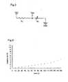
- Fig. 4is a graph showing an example of the relationship between the load acting on the winding yarn and the elongation rate of the winding yarn.
- the elongation rateis defined based on the natural length of the winding yarn.
- the loadhas a good correlation with the resistance value, i.e., when the weight of the load is 40 g or less, the elongation rate is as small as 1% or less, as shown in Fig. 4 . Therefore, when a winding yarn alone is used as an electrode, it is difficult to accurately extract biological signals that can be detected from body movements associated with respiration or the like.
- the winding yarn 4, 6 having the aforementioned propertiesis wound around the core yarn 2 composed of an elastic yarn. Therefore, even when the large amount of tension resulting from body movements acts on the pressure-sensitive conductive yarn 1 to greatly elongate the core yarn 2, the elongation of the winding yarn 4, 6 wound around the core yarn can be relatively suppressed. Accordingly, the entire elongation of the pressure-sensitive conductive yarn 1 can be detected as a small deformation of the winding yarn 4, 6, which allows for an accurate detection of biological signals associated with respiratory body movements or the like.
- Fig. 5is a graph showing an example of the relationship between the elongation rate and the resistance value according to the pressure-sensitive conductive yarn 1 of the present embodiment.
- the pressure-sensitive conductive yarn 1had an initial length of 100 mm, and the elongation rate was measured up to 20% in 4% increments.
- the resistance valuewas measured in the same manner as in the measurement of the winding yarn alone described above, and the test was conducted three times for the same pressure-sensitive conductive yarn 1. As shown in Fig. 5 , the resistance value was continuously changed until the elongation rate achieved 20%. This indicates that the pressure-sensitive conductive yarn of the present invention can detect a more significant elongation rate change as a resistance value change, compared to the results of the winding yarn alone, as shown in Figs. 2 and 4 .
- the winding yarns 4,6, each having a different winding directionare wound around the core yarn 2, which cancels out the torque, resulting in a stable yarn.
- the pressure-sensitive conductive yarn 1 of the present inventionhas a higher sensitivity than the pressure-sensitive conductive yarn having a single winding yarn.
- the winding yarnmay be single wound around the core yarn. In this case also, biological signals associated with body movements can be detected by suppressing the elongation of the winding yarn relative to the core yarn.
- the stretch properties of the core yarn 2is stabilized, which reduces hysteresis and provides the winding yarn 4, 6 with a length enough for the entire deformation.
- the winding yarn 4, 6can be utilized in a stable deformation range, which allows for a stable detection compared to when the winding yarn 4, 6 is utilized alone without the core material 2.
- the pressure-sensitive conductive yarn 1 as mentioned aboveis formed into a woven or knitted fabric to produce a sheet-like electrode.
- a biological information-measuring garmentcan be obtained by sewing the electrode on a garment.
- Fig. 6is a schematic configuration view of the biological information-measuring garment according to one embodiment of the present invention.
- the biological information-measuring garment 10 shown in Fig. 6is used for measuring heart rate and respiration at the same time, and is provided with two different electrodes 14, 16 and a GND electrode (indifferent electrode) 18 inside the garment body 12.
- the garment body 12be in the form of a T-shirt composed of a nonconductive material such as highly elastic polyurethane, and have a certain level of stretch properties so that the provided electrodes 14, 16, and 18 are easily attached to the body.
- the different electrodes 14, 16are provided on the right clavicular region and left subcostal region, respectively, according to the bipolar lead II of an ECG system, and the GND electrode 18 is provided on the left clavicular region.
- the different electrode 14 placed on the right clavicular region, different electrode 16 placed on the left subcostal region, and GND electrode 18are all woven fabrics made of the pressure-sensitive conductive yarn 1 of Fig. 1 , and are fixed to the garment body 12 by sewing or the like.
- the size of the different electrodes 14, 16is, for example, about 60 ⁇ 30(mm).
- knitted fabrics or the like composed of the pressure-sensitive conductive yarn 1may be provided as shields on the front side of the garment body 12 at the regions corresponding to the different electrodes 14 and 16.
- an elastic bodysuch as urethane foam may be inserted between the garment body 12 and each of the different electrodes 14, 16 and GND electrode 18.
- shields and elastic bodiesare not essential for the present invention.
- the output voltagewhich is the potential difference of the different electrodes 14 and 16 based on the GND electrode 18, was measured.
- the gainwas set to x510, and a primary high pass filter (HPF) having a cutoff frequency of 0.05 Hz and a fourth-order low pass filter (LPF) having a cutoff frequency of 30 Hz were used.
- HPFprimary high pass filter
- LPFfourth-order low pass filter
- An example of the output voltageis shown in Fig. 7 .
- the output voltagewas measured using a portable oscilloscope (ZR-MDR 10, produced by OMRON Corporation). It is possible to enter the value of the output voltage in the wristwatch-type information processing device to display and store it.
- the output voltage shown in Fig. 7includes a heart rate signal based on the electrocardiogram, as well as a respiration signal emitted from respiratory trunk movements. Specifically, when the elongation or contraction of the different electrode 16 on the left subcostal region causes a small deformation on the winding yarn 4, 6, the baseline oscillates due to the differential motion with the different electrode 14 on the right clavicular region. Using this information, respiration can be detected.
- heart rate signalswere extracted by filtering the output voltage by HPF at 0.8 Hz while respiration signals were extracted by LPF at 0.8 Hz.
- the separated heart rate signals and respiration signalsare shown in Fig. 8(a) and Fig. 9(a) , respectively.
- the reference signals of each of the heart rate signals and respiration signalswere measured.
- a disposable electrodeBlue Sensor, produced by Ambu
- a respiration pick-up(AP-C022, produced by Futami ME) were used for detecting the reference signals of the heart rate and that of the respiration, respectively.
- the signalsare simultaneously measured and recorded using a Polymate (AP1524, produced by TECH).
- Fig. 8(b) and Fig. 9(b)show the heart rate reference signals and respiration reference signals, respectively.
- the location and the number of electrodesare not particularly limited, and can be suitably changed depending on the subject biological information and measurement principal, such as electromyography and brain waves.
- the form of the garment body 12 on which the electrodes are attachedis not limited to T-shirts, and any garment or clothing accessory can be selected in accordance with the location of the electrodes.
- both electrodesare formed using the pressure-sensitive conductive yarn of the present invention; however, only one side of the electrodes, i.e., the electrode placed on the region elongated and contracted by body movements, may be formed of the pressure-sensitive conductive yarn of the present invention.
- the biological information-measuring garment of the present inventioncan simultaneously detect biological signals that result from body movements, such as respiration, movement of the shoulder joints, leaning of the trunk, movement of the neck by feeling of fullness or swallowing, etc. Therefore, the present invention is particularly appropriate for this purpose.
Landscapes
- Health & Medical Sciences (AREA)
- Engineering & Computer Science (AREA)
- Life Sciences & Earth Sciences (AREA)
- Textile Engineering (AREA)
- General Health & Medical Sciences (AREA)
- Biomedical Technology (AREA)
- Veterinary Medicine (AREA)
- Heart & Thoracic Surgery (AREA)
- Medical Informatics (AREA)
- Molecular Biology (AREA)
- Surgery (AREA)
- Animal Behavior & Ethology (AREA)
- Pathology (AREA)
- Public Health (AREA)
- Physics & Mathematics (AREA)
- Cardiology (AREA)
- Physiology (AREA)
- Mechanical Engineering (AREA)
- Biophysics (AREA)
- Physical Education & Sports Medicine (AREA)
- Pulmonology (AREA)
- Measurement And Recording Of Electrical Phenomena And Electrical Characteristics Of The Living Body (AREA)
- Measurement Of The Respiration, Hearing Ability, Form, And Blood Characteristics Of Living Organisms (AREA)
- Measuring Pulse, Heart Rate, Blood Pressure Or Blood Flow (AREA)
Description
- The present invention relates to a pressure-sensitive conductive yarn and a garment for measuring biological information.
- Biological information, e.g., respiration, heart rate, etc., is an important index for determining health conditions; however, known biological signal measurements require application of electrodes using gel, the wrapping of respiration bands, etc., causing great discomfort to the body.
- To eliminate such discomfort and facilitate daily health management, some attempts have been made to allow for the detection of biological information in a natural state by applying electrodes to a garment. For example,
Patent Document 1 discloses providing electrodes formed of a conductive yarn on a garment to detect pulse signals.
Patent Document 1: Japanese Unexamined Patent Publication No.2005-525477 WO-A-03094717 US-A-2006/211934 discloses textile-based electrodes, which can be used in the form of a wearable article.WO-A-2004/097089 andDE-A-10 2006 058 765 disclose an electrically conductive elastic composite yarn.JP-A-1000 1851 JP-A-2000 239 932 - However, a known electrode made of a conductive yarn can detect only one kind of biological information from detected signals; therefore, another electrode is required to measure other biological information such as respiration signals, etc., together with pulse signals.
However, this may cause discomfort during wear. - An object of the present invention is to provide a pressure-sensitive conductive yarn that is capable of detecting different biological information simultaneously when used as an electrode, and further a biological information-measuring garment including the pressure-sensitive conductive yarn.
- The object of the present invention is achieved by a pressure-sensitive conductive yarn comprising a core yarn formed of an elastic yarn around which a winding yarn having conductivity is wound, wherein the winding yarn is formed by mixing a plurality of conductive fibers and nonconductive fibers, and spinning these fibers, to cause variations in electrical resistance with elongation or contraction.
- In the pressure-sensitive conductive yarn, it is preferable that two winding yarns are wound around the core yarn, and that the winding direction of the first yarn is opposite to the winding direction of the second yarn.
- The object of the present invention can be achieved by a biological information-measuring garment comprising electrodes that are arranged on the garment formed of a nonconductive material in such a manner as to closely contact with the body, wherein the electrodes are formed of the pressure-sensitive conductive yarn.
- According to the biological information-measuring garment of the invention, a heart rate signal and respiration signal can be simultaneously extracted based on the output signals from the electrodes as different electrodes and a GND-electrode.
- When the pressure-sensitive conductive yarn of the present invention is used as an electrode, different biological information can be detected at the same time.
Fig. 1 is a schematic configuration view of one embodiment of the pressure-sensitive conductive yarn of the present invention.Fig. 2 is a graph showing an example of the relationship between the tension (load) on the winding yarn, and the resistance value.Fig. 3 is a configuration view of a measurement circuit used in the measurement shown inFig. 2 .Fig. 4 is a graph showing an example of the relationship between the load on the winding yarn and the elongation rate of the winding yarn.Fig. 5 is a graph showing the relationship between the elongation rate and the resistance value according to one embodiment of the pressure-sensitive conductive yarn.Fig. 6 is a schematic configuration view of one embodiment of the biological information-measuring garment of the present invention.Fig. 7 is a graph showing an example of the wave pattern of the output voltage detected from the biological information-measuring garment ofFig. 6 .Fig. 8(a) is a graph showing an example of the measurement results of heart rate signals.Fig. 8(b) is a graph showing an example of the reference signals of the heart rate signals.Fig. 9(a) is a graph showing an example of respiration signals.Fig. 9(b) is a graph showing an example of the reference signals of the respiration signals.- 1: Pressure-sensitive conductive yarn
- 2: Core yarn
- 4, 6: Winding yarn
- 10: Biological information-measuring garment
- 12: Garment body
- 14,16: Different electrode
- 18: GND electrode
- Embodiments of the present invention will now be described with reference to the accompanying drawings.
Fig. 1 is a schematic configuration view of one embodiment of the pressure-sensitive conductive yarn of the present invention. As shown inFig. 1 , the pressure-sensitiveconductive yarn 1 is formed by doublewinding thewinding yarn core yarn 2 composed of elastic yarn such as polyurethane. The winding direction of thefirst winding yarn 4 is opposite that of thesecond winding yarn 6. The pressure-sensitiveconductive yarn 1 is produced by the same method as that of known double covering yarns.- The
winding yarn 2003-20538 winding yarn winding yarn Fig. 2 is a graph showing an example of the relationship between the tension (load) on the winding yarn and the resistance value, and shows the measurement results of five winding yarns. As a winding yarn, a yarn having a blending ratio of 70/30 (polyester fiber/stainless fiber) was used. With the winding yarn (300 mm) having a weight at the end, changes in the resistance value of the winding yarn were measured using the measurement circuit ofFig. 3 . InFig. 3 , VCC indicates a constant voltage (5V); R1, metal film resistor (1kΩ); and Rx, resistance of the subject winding yarn. The resistance value of Rx was calculated based on the output voltage (Vout) obtained when the VCC was divided by R1 and Rx. Water was used as a weight, and increased in 5 g increments up to 150 g. The measurement of "Vout" was conducted using a portable oscilloscope (ZR-MDR 10, produced by OMRON Corporation) at a sampling rate of 200 Hz.- As shown in
Fig. 2 , when the weight of the load is about 40 g or less, the resistance values of all of the winding yarns are significantly decreased as the load increases. This indicates that there is a correlation between the tension acting on the winding yarn and the resistance value. In contrast, when the weight of the load is 40 g or more, almost no change was observed in the resistance values of the winding yarns. This indicates that the measurement of the resistant value does not help to uniquely determine the weight of the load. Fig. 4 is a graph showing an example of the relationship between the load acting on the winding yarn and the elongation rate of the winding yarn. The elongation rate is defined based on the natural length of the winding yarn. When the load has a good correlation with the resistance value, i.e., when the weight of the load is 40 g or less, the elongation rate is as small as 1% or less, as shown inFig. 4 . Therefore, when a winding yarn alone is used as an electrode, it is difficult to accurately extract biological signals that can be detected from body movements associated with respiration or the like.- On the other hand, in the pressure-sensitive
conductive yarn 1 of the present embodiment, the windingyarn core yarn 2 composed of an elastic yarn. Therefore, even when the large amount of tension resulting from body movements acts on the pressure-sensitiveconductive yarn 1 to greatly elongate thecore yarn 2, the elongation of the windingyarn conductive yarn 1 can be detected as a small deformation of the windingyarn Fig. 5 is a graph showing an example of the relationship between the elongation rate and the resistance value according to the pressure-sensitiveconductive yarn 1 of the present embodiment. The pressure-sensitiveconductive yarn 1 had an initial length of 100 mm, and the elongation rate was measured up to 20% in 4% increments. The resistance value was measured in the same manner as in the measurement of the winding yarn alone described above, and the test was conducted three times for the same pressure-sensitiveconductive yarn 1. As shown inFig. 5 , the resistance value was continuously changed until the elongation rate achieved 20%. This indicates that the pressure-sensitive conductive yarn of the present invention can detect a more significant elongation rate change as a resistance value change, compared to the results of the winding yarn alone, as shown inFigs. 2 and4 .- In the pressure-sensitive
conductive yarn 1 of the present embodiment, the windingyarns core yarn 2, which cancels out the torque, resulting in a stable yarn. Further, due to the variations in the contact density of the windingyarns conductive yarn 1 of the present invention has a higher sensitivity than the pressure-sensitive conductive yarn having a single winding yarn. However, the winding yarn may be single wound around the core yarn. In this case also, biological signals associated with body movements can be detected by suppressing the elongation of the winding yarn relative to the core yarn. - Further, by employing the covering structure in which a material having stretch properties is used as the
core yarn 2, the stretch properties of thecore yarn 2 is stabilized, which reduces hysteresis and provides the windingyarn yarn yarn core material 2. - The pressure-sensitive
conductive yarn 1 as mentioned above is formed into a woven or knitted fabric to produce a sheet-like electrode. A biological information-measuring garment can be obtained by sewing the electrode on a garment. Fig. 6 is a schematic configuration view of the biological information-measuring garment according to one embodiment of the present invention. The biological information-measuringgarment 10 shown inFig. 6 is used for measuring heart rate and respiration at the same time, and is provided with twodifferent electrodes garment body 12. It is preferable that thegarment body 12 be in the form of a T-shirt composed of a nonconductive material such as highly elastic polyurethane, and have a certain level of stretch properties so that the providedelectrodes - The
different electrodes GND electrode 18 is provided on the left clavicular region. Thedifferent electrode 14 placed on the right clavicular region,different electrode 16 placed on the left subcostal region, andGND electrode 18 are all woven fabrics made of the pressure-sensitiveconductive yarn 1 ofFig. 1 , and are fixed to thegarment body 12 by sewing or the like. The size of thedifferent electrodes - To reduce the effects of noise from commercial power supplies, knitted fabrics or the like composed of the pressure-sensitive
conductive yarn 1 may be provided as shields on the front side of thegarment body 12 at the regions corresponding to thedifferent electrodes different electrodes GND electrode 18, an elastic body such as urethane foam may be inserted between thegarment body 12 and each of thedifferent electrodes GND electrode 18. However, such shields and elastic bodies are not essential for the present invention. - With the subject wearing the biological information-measuring
garment 10 ofFig. 6 , the output voltage, which is the potential difference of thedifferent electrodes GND electrode 18, was measured. The gain was set to x510, and a primary high pass filter (HPF) having a cutoff frequency of 0.05 Hz and a fourth-order low pass filter (LPF) having a cutoff frequency of 30 Hz were used. An example of the output voltage is shown inFig. 7 . The output voltage was measured using a portable oscilloscope (ZR-MDR 10, produced by OMRON Corporation). It is possible to enter the value of the output voltage in the wristwatch-type information processing device to display and store it. - The output voltage shown in
Fig. 7 includes a heart rate signal based on the electrocardiogram, as well as a respiration signal emitted from respiratory trunk movements. Specifically, when the elongation or contraction of thedifferent electrode 16 on the left subcostal region causes a small deformation on the windingyarn different electrode 14 on the right clavicular region. Using this information, respiration can be detected. - In conducting the measurement, heart rate signals were extracted by filtering the output voltage by HPF at 0.8 Hz while respiration signals were extracted by LPF at 0.8 Hz. The separated heart rate signals and respiration signals are shown in
Fig. 8(a) and Fig. 9(a) , respectively. - At the same time, the reference signals of each of the heart rate signals and respiration signals were measured. A disposable electrode (Blue Sensor, produced by Ambu) and a respiration pick-up (AP-C022, produced by Futami ME) were used for detecting the reference signals of the heart rate and that of the respiration, respectively. The signals are simultaneously measured and recorded using a Polymate (AP1524, produced by TECH).
Fig. 8(b) and Fig. 9(b) show the heart rate reference signals and respiration reference signals, respectively. - The comparison between
Figs. 8(a) and (b) , and the comparison betweenFigs. 9(a) and (b) reveal that both of the heart rate signals and respiration signals have wave patterns similar to those of the reference signals, indicating that the biological information-measuringgarment 10 of the present embodiment can detect a heart rate signal and respiration signal at the same time. - In the biological information-measuring
garment 10 of the present embodiment, the location and the number of electrodes are not particularly limited, and can be suitably changed depending on the subject biological information and measurement principal, such as electromyography and brain waves. Further, the form of thegarment body 12 on which the electrodes are attached is not limited to T-shirts, and any garment or clothing accessory can be selected in accordance with the location of the electrodes. In the present embodiment, both electrodes are formed using the pressure-sensitive conductive yarn of the present invention; however, only one side of the electrodes, i.e., the electrode placed on the region elongated and contracted by body movements, may be formed of the pressure-sensitive conductive yarn of the present invention. - In addition to the known biological signal measurements using an electrode, the biological information-measuring garment of the present invention can simultaneously detect biological signals that result from body movements, such as respiration, movement of the shoulder joints, leaning of the trunk, movement of the neck by feeling of fullness or swallowing, etc. Therefore, the present invention is particularly appropriate for this purpose.
Claims (4)
- A pressure-sensitive conductive yarn (1) comprising a core yarn (2) formed of an elastic yarn around which a winding yarn (4, 6) having conductivity is wound,characterised in that the winding yarn (4, 6) is formed by mixing a plurality of conductive fibers and a plurality of nonconductive fibers, and spinning these fibers, to cause variations in its electrical resistance with elongation or contraction.
- The pressure-sensitive conductive yarn (1) according to claim 1, wherein two winding yarns are wound around the core yarn (2) the winding direction of the first yarn (4) being opposite to the winding direction of the second yarn (6).
- A biological information-measuring garment (10) comprising electrodes (14, 16, 18) provided on the garment formed of a nonconductive material in such a manner as to closely contact with the body, wherein the electrodes (14, 16, 18) are formed using the pressure-sensitive conductive yarn according to claim 1 or 2.
- The biological information-measuring garment (10) according to claim 3, comprising two electrodes (14, 16) as different electrodes and a GND-electrode (18), wherein a heart rate signal and respiration signal can be simultaneously extracted based on an output signal, which is a potential difference of the two different electrodes (14, 16) based on the GND-electrode (18).
Applications Claiming Priority (1)
| Application Number | Priority Date | Filing Date | Title |
|---|---|---|---|
| JP2008274641AJP5413561B2 (en) | 2008-10-24 | 2008-10-24 | Pressure-sensitive conductive yarn and biological information measurement clothing |
Publications (2)
| Publication Number | Publication Date |
|---|---|
| EP2180091A1 EP2180091A1 (en) | 2010-04-28 |
| EP2180091B1true EP2180091B1 (en) | 2012-09-12 |
Family
ID=41664965
Family Applications (1)
| Application Number | Title | Priority Date | Filing Date |
|---|---|---|---|
| EP09013240ANot-in-forceEP2180091B1 (en) | 2008-10-24 | 2009-10-20 | Pressure-sensitive conductive yarn and biological information-measuring garment |
Country Status (4)
| Country | Link |
|---|---|
| US (1) | US20100105992A1 (en) |
| EP (1) | EP2180091B1 (en) |
| JP (1) | JP5413561B2 (en) |
| CN (1) | CN101728005A (en) |
Families Citing this family (27)
| Publication number | Priority date | Publication date | Assignee | Title |
|---|---|---|---|---|
| JP5750751B2 (en)* | 2010-08-20 | 2015-07-22 | 学校法人立命館 | Foot slip detection device and insole |
| CA2938025C (en)* | 2014-01-28 | 2021-11-16 | Nippon Telegraph And Telephone Corporation | Biosignal detecting garment |
| DE102014103978A1 (en)* | 2014-03-24 | 2015-09-24 | Ditf Deutsche Institute Für Textil- Und Faserforschung Stuttgart | Sensorgarn |
| JP6015705B2 (en)* | 2014-04-16 | 2016-10-26 | 住友電気工業株式会社 | Fabric and fittings |
| CN104499272B (en)* | 2015-01-15 | 2017-05-03 | 中国科学院上海硅酸盐研究所 | High-elasticity conductive fiber and preparation method thereof |
| JP2017031534A (en)* | 2015-08-03 | 2017-02-09 | グンゼ株式会社 | Stretchable clothing including conductive part |
| JP2017089052A (en)* | 2015-11-10 | 2017-05-25 | グンゼ株式会社 | Clothing for biometric data acquisition |
| CN106705829B (en)* | 2015-08-21 | 2019-06-11 | 中国科学院上海硅酸盐研究所 | A flexible wearable conductive fiber sensor and its preparation method and application |
| CN105336445B (en)* | 2015-11-27 | 2017-08-22 | 浙江力方健康科技有限公司 | A kind of electric wire manufacture method applied to wearable device |
| CN105326485A (en)* | 2015-12-07 | 2016-02-17 | 博迪加科技(北京)有限公司 | Smart clothing flexible sensor and flexible sensor module |
| JP6597318B2 (en)* | 2016-01-06 | 2019-10-30 | ヤマハ株式会社 | Strain sensor element |
| JP6706747B2 (en)* | 2016-02-18 | 2020-06-10 | 株式会社槌屋 | Strain measuring sensor |
| DE102016210603B4 (en) | 2016-06-15 | 2020-01-16 | Leoni Kabel Gmbh | Device, supply line for such, sensor line and method for torsion measurement |
| JP6986667B2 (en)* | 2016-08-25 | 2021-12-22 | グンゼ株式会社 | Wearing device for detecting human body movement |
| CN106894133A (en)* | 2017-03-03 | 2017-06-27 | 东华大学 | A kind of stretchable multi-dimensional force sensing yarn of resistance-type |
| CN106990293B (en)* | 2017-05-27 | 2023-04-07 | 河南省纺织产品质量监督检验院 | Resistance detection method and detection device for conductive yarn |
| EP3632304A4 (en)* | 2017-05-29 | 2021-03-03 | Toyobo Co., Ltd. | BIOMETRIC INFORMATION MEASUREMENT CLOTHING |
| CN109868590B (en)* | 2017-12-01 | 2022-07-08 | 香港理工大学 | Full-automatic embroidery manufacturing technology for wearable intelligent conductive textile |
| CN110499558B (en)* | 2018-05-16 | 2023-02-17 | 尚科纺织企业工业及贸易公司 | Composite yarn for position sensitive capacitive touch sensing |
| CN109253740B (en)* | 2018-09-10 | 2021-02-12 | 中原工学院 | Capacitive sensor based on nanofiber core-spun yarn and preparation method thereof |
| US12433509B2 (en) | 2019-09-09 | 2025-10-07 | Chronolife | Elongation sensor and wearable article including the elongation sensor |
| US11614375B2 (en) | 2019-12-19 | 2023-03-28 | City University Of Hong Kong | Electromechanical sensor, a method of producing such sensor and a wearable device including such sensor |
| CN113388940B (en)* | 2021-06-25 | 2023-04-28 | 浙江荣祥纺织股份有限公司 | Metal elastic yarn, fabric prepared from metal elastic yarn and production process of fabric |
| JP2023073775A (en)* | 2021-11-16 | 2023-05-26 | 新光電気工業株式会社 | Bioelectrodes, wearable devices and clothing |
| CN114622317B (en)* | 2022-04-09 | 2023-02-28 | 东华大学 | Resistance type strain sensing covered yarn and preparation method thereof |
| CN116147671B (en)* | 2022-08-26 | 2025-10-03 | 绍兴文理学院 | Large strain linear double helix structure flexible capacitive sensor and preparation method thereof |
| CN118857520B (en)* | 2024-07-01 | 2025-04-08 | 河南省黄河高速公路有限公司 | Steel inhaul cable monitoring device based on organic fibers, manufacturing method and monitoring method |
Citations (3)
| Publication number | Priority date | Publication date | Assignee | Title |
|---|---|---|---|---|
| JPH101851A (en)* | 1996-06-13 | 1998-01-06 | Mitsubishi Rayon Co Ltd | Antistatic short fiber aggregate and method for producing the same |
| JP2000239932A (en)* | 1999-02-22 | 2000-09-05 | Toray Ind Inc | Electroconductive spun yarn and fabric |
| JP2003020538A (en)* | 2001-07-06 | 2003-01-24 | Shigeto Kuroda | Electroconductive knitted fabric or woven fabric and sensor using the same |
Family Cites Families (22)
| Publication number | Priority date | Publication date | Assignee | Title |
|---|---|---|---|---|
| US3398233A (en)* | 1965-04-20 | 1968-08-20 | Dennis G Wyman | Electrical conductor of fibers embedded in an insulator |
| US4715235A (en)* | 1985-03-04 | 1987-12-29 | Asahi Kasei Kogyo Kabushiki Kaisha | Deformation sensitive electroconductive knitted or woven fabric and deformation sensitive electroconductive device comprising the same |
| JPH0227610A (en)* | 1988-07-18 | 1990-01-30 | Toyobo Co Ltd | Elastic conductive wire and its manufacture |
| JP3663285B2 (en)* | 1997-10-24 | 2005-06-22 | グンゼ株式会社 | Electrocardiogram electrode, electrocardiogram measurement clothing, and electrocardiogram measurement system |
| JP3986757B2 (en)* | 1998-01-19 | 2007-10-03 | 旭化成せんい株式会社 | Lint free wiper |
| CN1286000C (en)* | 2000-04-03 | 2006-11-22 | 布鲁内尔大学 | Conductive pressure sensitive textile |
| EP2324760B1 (en)* | 2000-04-17 | 2019-07-24 | Adidas AG | System for ambulatory monitoring of physiological signs |
| US6341504B1 (en)* | 2001-01-31 | 2002-01-29 | Vivometrics, Inc. | Composite elastic and wire fabric for physiological monitoring apparel |
| US6783498B2 (en)* | 2002-03-26 | 2004-08-31 | Vivometrics, Inc. | Method and system for extracting cardiac parameters from plethysmographic signals |
| GB0210888D0 (en)* | 2002-05-14 | 2002-06-19 | Koninkl Philips Electronics Nv | Textile article and method for producing the same |
| CN100523341C (en)* | 2002-09-14 | 2009-08-05 | W·齐默尔曼两合公司 | conductive yarn |
| US7135227B2 (en)* | 2003-04-25 | 2006-11-14 | Textronics, Inc. | Electrically conductive elastic composite yarn, methods for making the same, and articles incorporating the same |
| JPWO2005032368A1 (en)* | 2003-10-03 | 2007-11-15 | アップリカ育児研究会アップリカ▲葛▼西株式会社 | Infant clothing with biometric sensor, infant seat with biometric sensor, and biometric method |
| US20050124245A1 (en)* | 2003-12-03 | 2005-06-09 | Tianyi Liao | Size-covered composite yarns and method for making same |
| JP4609923B2 (en)* | 2004-06-11 | 2011-01-12 | 国立大学法人岐阜大学 | Elastic clothing |
| GB0414731D0 (en)* | 2004-07-01 | 2004-08-04 | Koninkl Philips Electronics Nv | A fabric sensor and a garment incorporating the sensor |
| US7308294B2 (en)* | 2005-03-16 | 2007-12-11 | Textronics Inc. | Textile-based electrode system |
| SI1885925T1 (en)* | 2005-06-02 | 2011-01-31 | Bekaert Sa Nv | Electrically conductive elastic composite yarn |
| US20060281382A1 (en)* | 2005-06-10 | 2006-12-14 | Eleni Karayianni | Surface functional electro-textile with functionality modulation capability, methods for making the same, and applications incorporating the same |
| DE102006058765A1 (en)* | 2006-12-12 | 2008-06-26 | W. Zimmermann Gmbh & Co. Kg | Method for measuring electrical characteristics of conductive yarn, involves providing electrical circuit having electrically conductive yarn and electrical signal is transmitted into conductive yarn |
| TWI317630B (en)* | 2007-03-12 | 2009-12-01 | Taiwan Textile Res Inst | Respiration monitoring system |
| EP2236654B1 (en)* | 2009-04-02 | 2012-02-08 | Electronica Santamaria S.L. | Electrically conductive, elastic composite yarn, corresponding device and manufacturing method |
- 2008
- 2008-10-24JPJP2008274641Apatent/JP5413561B2/ennot_activeExpired - Fee Related
- 2009
- 2009-10-16USUS12/588,498patent/US20100105992A1/ennot_activeAbandoned
- 2009-10-20EPEP09013240Apatent/EP2180091B1/ennot_activeNot-in-force
- 2009-10-26CNCN200910179662Apatent/CN101728005A/enactivePending
Patent Citations (3)
| Publication number | Priority date | Publication date | Assignee | Title |
|---|---|---|---|---|
| JPH101851A (en)* | 1996-06-13 | 1998-01-06 | Mitsubishi Rayon Co Ltd | Antistatic short fiber aggregate and method for producing the same |
| JP2000239932A (en)* | 1999-02-22 | 2000-09-05 | Toray Ind Inc | Electroconductive spun yarn and fabric |
| JP2003020538A (en)* | 2001-07-06 | 2003-01-24 | Shigeto Kuroda | Electroconductive knitted fabric or woven fabric and sensor using the same |
Also Published As
| Publication number | Publication date |
|---|---|
| CN101728005A (en) | 2010-06-09 |
| US20100105992A1 (en) | 2010-04-29 |
| JP5413561B2 (en) | 2014-02-12 |
| JP2010099327A (en) | 2010-05-06 |
| EP2180091A1 (en) | 2010-04-28 |
Similar Documents
| Publication | Publication Date | Title |
|---|---|---|
| EP2180091B1 (en) | Pressure-sensitive conductive yarn and biological information-measuring garment | |
| CN103379851B (en) | Sensors for Acquiring Physiological Signals | |
| US11253203B2 (en) | Object, method, and system for detecting heartbeat or whether or not electrodes are in proper contact | |
| EP1942799B1 (en) | Physiological monitoring wearable having three electrodes | |
| TWI689263B (en) | Device for monitoring a physiological parameter of a user as a clothing item | |
| JP3663285B2 (en) | Electrocardiogram electrode, electrocardiogram measurement clothing, and electrocardiogram measurement system | |
| CN107334189B (en) | Wearable pedometer system | |
| JP2017512102A (en) | Elastic conductive stripe and method of use thereof | |
| JP2011015818A (en) | Device for measuring bioelectric signal | |
| Gaubert et al. | Smart underwear, incorporating textrodes, to estimate the bladder volume: Proof of concept on a test bench | |
| US12433509B2 (en) | Elongation sensor and wearable article including the elongation sensor | |
| US20220000424A1 (en) | Garment, measurement apparatus and monitoring system | |
| KR101009541B1 (en) | Sensor for biosignal measurement module and manufacturing method thereof, and clothing with sensor for biosignal measurement module | |
| US12331432B2 (en) | Electrically conductive yarn and wearable article including such yarn | |
| EP4544999A1 (en) | Biometric information measurement device | |
| Paradiso et al. | Textiles and smart materials for wearable monitoring systems | |
| TWI294000B (en) | Electrically conductive textile for monitoring deformation | |
| WO2020148828A1 (en) | Seat belt and state identifying device | |
| Perego et al. | Textile performance assessment for smart T-shirt development | |
| JP2020503155A (en) | Disturbance indicator for wearable devices |
Legal Events
| Date | Code | Title | Description |
|---|---|---|---|
| PUAI | Public reference made under article 153(3) epc to a published international application that has entered the european phase | Free format text:ORIGINAL CODE: 0009012 | |
| AK | Designated contracting states | Kind code of ref document:A1 Designated state(s):AT BE BG CH CY CZ DE DK EE ES FI FR GB GR HR HU IE IS IT LI LT LU LV MC MK MT NL NO PL PT RO SE SI SK SM TR | |
| AX | Request for extension of the european patent | Extension state:AL BA RS | |
| 17P | Request for examination filed | Effective date:20100602 | |
| 17Q | First examination report despatched | Effective date:20101229 | |
| GRAP | Despatch of communication of intention to grant a patent | Free format text:ORIGINAL CODE: EPIDOSNIGR1 | |
| GRAS | Grant fee paid | Free format text:ORIGINAL CODE: EPIDOSNIGR3 | |
| GRAA | (expected) grant | Free format text:ORIGINAL CODE: 0009210 | |
| AK | Designated contracting states | Kind code of ref document:B1 Designated state(s):AT BE BG CH CY CZ DE DK EE ES FI FR GB GR HR HU IE IS IT LI LT LU LV MC MK MT NL NO PL PT RO SE SI SK SM TR | |
| REG | Reference to a national code | Ref country code:GB Ref legal event code:FG4D | |
| REG | Reference to a national code | Ref country code:CH Ref legal event code:EP | |
| REG | Reference to a national code | Ref country code:AT Ref legal event code:REF Ref document number:575155 Country of ref document:AT Kind code of ref document:T Effective date:20120915 | |
| REG | Reference to a national code | Ref country code:IE Ref legal event code:FG4D | |
| REG | Reference to a national code | Ref country code:DE Ref legal event code:R096 Ref document number:602009009627 Country of ref document:DE Effective date:20121108 | |
| PG25 | Lapsed in a contracting state [announced via postgrant information from national office to epo] | Ref country code:FI Free format text:LAPSE BECAUSE OF FAILURE TO SUBMIT A TRANSLATION OF THE DESCRIPTION OR TO PAY THE FEE WITHIN THE PRESCRIBED TIME-LIMIT Effective date:20120912 Ref country code:HR Free format text:LAPSE BECAUSE OF FAILURE TO SUBMIT A TRANSLATION OF THE DESCRIPTION OR TO PAY THE FEE WITHIN THE PRESCRIBED TIME-LIMIT Effective date:20120912 Ref country code:LT Free format text:LAPSE BECAUSE OF FAILURE TO SUBMIT A TRANSLATION OF THE DESCRIPTION OR TO PAY THE FEE WITHIN THE PRESCRIBED TIME-LIMIT Effective date:20120912 Ref country code:NO Free format text:LAPSE BECAUSE OF FAILURE TO SUBMIT A TRANSLATION OF THE DESCRIPTION OR TO PAY THE FEE WITHIN THE PRESCRIBED TIME-LIMIT Effective date:20121212 Ref country code:CY Free format text:LAPSE BECAUSE OF FAILURE TO SUBMIT A TRANSLATION OF THE DESCRIPTION OR TO PAY THE FEE WITHIN THE PRESCRIBED TIME-LIMIT Effective date:20120912 | |
| PGFP | Annual fee paid to national office [announced via postgrant information from national office to epo] | Ref country code:DE Payment date:20121030 Year of fee payment:4 Ref country code:FR Payment date:20121127 Year of fee payment:4 | |
| REG | Reference to a national code | Ref country code:NL Ref legal event code:VDEP Effective date:20120912 | |
| REG | Reference to a national code | Ref country code:AT Ref legal event code:MK05 Ref document number:575155 Country of ref document:AT Kind code of ref document:T Effective date:20120912 | |
| REG | Reference to a national code | Ref country code:LT Ref legal event code:MG4D Effective date:20120912 | |
| PG25 | Lapsed in a contracting state [announced via postgrant information from national office to epo] | Ref country code:SE Free format text:LAPSE BECAUSE OF FAILURE TO SUBMIT A TRANSLATION OF THE DESCRIPTION OR TO PAY THE FEE WITHIN THE PRESCRIBED TIME-LIMIT Effective date:20120912 Ref country code:LV Free format text:LAPSE BECAUSE OF FAILURE TO SUBMIT A TRANSLATION OF THE DESCRIPTION OR TO PAY THE FEE WITHIN THE PRESCRIBED TIME-LIMIT Effective date:20120912 Ref country code:GR Free format text:LAPSE BECAUSE OF FAILURE TO SUBMIT A TRANSLATION OF THE DESCRIPTION OR TO PAY THE FEE WITHIN THE PRESCRIBED TIME-LIMIT Effective date:20121213 Ref country code:SI Free format text:LAPSE BECAUSE OF FAILURE TO SUBMIT A TRANSLATION OF THE DESCRIPTION OR TO PAY THE FEE WITHIN THE PRESCRIBED TIME-LIMIT Effective date:20120912 | |
| PGFP | Annual fee paid to national office [announced via postgrant information from national office to epo] | Ref country code:IT Payment date:20121031 Year of fee payment:4 | |
| PG25 | Lapsed in a contracting state [announced via postgrant information from national office to epo] | Ref country code:CZ Free format text:LAPSE BECAUSE OF FAILURE TO SUBMIT A TRANSLATION OF THE DESCRIPTION OR TO PAY THE FEE WITHIN THE PRESCRIBED TIME-LIMIT Effective date:20120912 Ref country code:EE Free format text:LAPSE BECAUSE OF FAILURE TO SUBMIT A TRANSLATION OF THE DESCRIPTION OR TO PAY THE FEE WITHIN THE PRESCRIBED TIME-LIMIT Effective date:20120912 Ref country code:NL Free format text:LAPSE BECAUSE OF FAILURE TO SUBMIT A TRANSLATION OF THE DESCRIPTION OR TO PAY THE FEE WITHIN THE PRESCRIBED TIME-LIMIT Effective date:20120912 Ref country code:BE Free format text:LAPSE BECAUSE OF FAILURE TO SUBMIT A TRANSLATION OF THE DESCRIPTION OR TO PAY THE FEE WITHIN THE PRESCRIBED TIME-LIMIT Effective date:20120912 Ref country code:ES Free format text:LAPSE BECAUSE OF FAILURE TO SUBMIT A TRANSLATION OF THE DESCRIPTION OR TO PAY THE FEE WITHIN THE PRESCRIBED TIME-LIMIT Effective date:20121223 Ref country code:IS Free format text:LAPSE BECAUSE OF FAILURE TO SUBMIT A TRANSLATION OF THE DESCRIPTION OR TO PAY THE FEE WITHIN THE PRESCRIBED TIME-LIMIT Effective date:20130112 Ref country code:RO Free format text:LAPSE BECAUSE OF FAILURE TO SUBMIT A TRANSLATION OF THE DESCRIPTION OR TO PAY THE FEE WITHIN THE PRESCRIBED TIME-LIMIT Effective date:20120912 | |
| PG25 | Lapsed in a contracting state [announced via postgrant information from national office to epo] | Ref country code:PT Free format text:LAPSE BECAUSE OF FAILURE TO SUBMIT A TRANSLATION OF THE DESCRIPTION OR TO PAY THE FEE WITHIN THE PRESCRIBED TIME-LIMIT Effective date:20130114 Ref country code:PL Free format text:LAPSE BECAUSE OF FAILURE TO SUBMIT A TRANSLATION OF THE DESCRIPTION OR TO PAY THE FEE WITHIN THE PRESCRIBED TIME-LIMIT Effective date:20120912 Ref country code:MC Free format text:LAPSE BECAUSE OF NON-PAYMENT OF DUE FEES Effective date:20121031 Ref country code:SK Free format text:LAPSE BECAUSE OF FAILURE TO SUBMIT A TRANSLATION OF THE DESCRIPTION OR TO PAY THE FEE WITHIN THE PRESCRIBED TIME-LIMIT Effective date:20120912 | |
| PG25 | Lapsed in a contracting state [announced via postgrant information from national office to epo] | Ref country code:AT Free format text:LAPSE BECAUSE OF FAILURE TO SUBMIT A TRANSLATION OF THE DESCRIPTION OR TO PAY THE FEE WITHIN THE PRESCRIBED TIME-LIMIT Effective date:20120912 | |
| REG | Reference to a national code | Ref country code:IE Ref legal event code:MM4A | |
| PLBE | No opposition filed within time limit | Free format text:ORIGINAL CODE: 0009261 | |
| STAA | Information on the status of an ep patent application or granted ep patent | Free format text:STATUS: NO OPPOSITION FILED WITHIN TIME LIMIT | |
| PG25 | Lapsed in a contracting state [announced via postgrant information from national office to epo] | Ref country code:BG Free format text:LAPSE BECAUSE OF FAILURE TO SUBMIT A TRANSLATION OF THE DESCRIPTION OR TO PAY THE FEE WITHIN THE PRESCRIBED TIME-LIMIT Effective date:20121212 Ref country code:IE Free format text:LAPSE BECAUSE OF NON-PAYMENT OF DUE FEES Effective date:20121020 Ref country code:DK Free format text:LAPSE BECAUSE OF FAILURE TO SUBMIT A TRANSLATION OF THE DESCRIPTION OR TO PAY THE FEE WITHIN THE PRESCRIBED TIME-LIMIT Effective date:20120912 | |
| 26N | No opposition filed | Effective date:20130613 | |
| REG | Reference to a national code | Ref country code:DE Ref legal event code:R097 Ref document number:602009009627 Country of ref document:DE Effective date:20130613 | |
| PG25 | Lapsed in a contracting state [announced via postgrant information from national office to epo] | Ref country code:MT Free format text:LAPSE BECAUSE OF FAILURE TO SUBMIT A TRANSLATION OF THE DESCRIPTION OR TO PAY THE FEE WITHIN THE PRESCRIBED TIME-LIMIT Effective date:20120912 | |
| PG25 | Lapsed in a contracting state [announced via postgrant information from national office to epo] | Ref country code:TR Free format text:LAPSE BECAUSE OF FAILURE TO SUBMIT A TRANSLATION OF THE DESCRIPTION OR TO PAY THE FEE WITHIN THE PRESCRIBED TIME-LIMIT Effective date:20120912 | |
| PG25 | Lapsed in a contracting state [announced via postgrant information from national office to epo] | Ref country code:SM Free format text:LAPSE BECAUSE OF FAILURE TO SUBMIT A TRANSLATION OF THE DESCRIPTION OR TO PAY THE FEE WITHIN THE PRESCRIBED TIME-LIMIT Effective date:20120912 Ref country code:LU Free format text:LAPSE BECAUSE OF NON-PAYMENT OF DUE FEES Effective date:20121020 | |
| REG | Reference to a national code | Ref country code:CH Ref legal event code:PL | |
| GBPC | Gb: european patent ceased through non-payment of renewal fee | Effective date:20131020 | |
| REG | Reference to a national code | Ref country code:DE Ref legal event code:R119 Ref document number:602009009627 Country of ref document:DE Effective date:20140501 | |
| PG25 | Lapsed in a contracting state [announced via postgrant information from national office to epo] | Ref country code:CH Free format text:LAPSE BECAUSE OF NON-PAYMENT OF DUE FEES Effective date:20131031 Ref country code:LI Free format text:LAPSE BECAUSE OF NON-PAYMENT OF DUE FEES Effective date:20131031 Ref country code:GB Free format text:LAPSE BECAUSE OF NON-PAYMENT OF DUE FEES Effective date:20131020 Ref country code:HU Free format text:LAPSE BECAUSE OF FAILURE TO SUBMIT A TRANSLATION OF THE DESCRIPTION OR TO PAY THE FEE WITHIN THE PRESCRIBED TIME-LIMIT Effective date:20091020 | |
| REG | Reference to a national code | Ref country code:FR Ref legal event code:ST Effective date:20140630 | |
| PG25 | Lapsed in a contracting state [announced via postgrant information from national office to epo] | Ref country code:FR Free format text:LAPSE BECAUSE OF NON-PAYMENT OF DUE FEES Effective date:20131031 Ref country code:IT Free format text:LAPSE BECAUSE OF NON-PAYMENT OF DUE FEES Effective date:20131020 Ref country code:DE Free format text:LAPSE BECAUSE OF NON-PAYMENT OF DUE FEES Effective date:20140501 | |
| PG25 | Lapsed in a contracting state [announced via postgrant information from national office to epo] | Ref country code:MK Free format text:LAPSE BECAUSE OF FAILURE TO SUBMIT A TRANSLATION OF THE DESCRIPTION OR TO PAY THE FEE WITHIN THE PRESCRIBED TIME-LIMIT Effective date:20120912 |