EP2176696B1 - Fiber optic enclosure with internal cable spool - Google Patents
Fiber optic enclosure with internal cable spoolDownload PDFInfo
- Publication number
- EP2176696B1 EP2176696B1EP08837186.9AEP08837186AEP2176696B1EP 2176696 B1EP2176696 B1EP 2176696B1EP 08837186 AEP08837186 AEP 08837186AEP 2176696 B1EP2176696 B1EP 2176696B1
- Authority
- EP
- European Patent Office
- Prior art keywords
- fiber optic
- cable
- spool
- housing
- optic enclosure
- Prior art date
- Legal status (The legal status is an assumption and is not a legal conclusion. Google has not performed a legal analysis and makes no representation as to the accuracy of the status listed.)
- Active
Links
- 239000000835fiberSubstances0.000titleclaimsdescription139
- 238000000034methodMethods0.000claimsdescription13
- 239000013307optical fiberSubstances0.000claimsdescription10
- 238000009434installationMethods0.000description3
- 238000004806packaging method and processMethods0.000description3
- 239000006260foamSubstances0.000description2
- 230000014759maintenance of locationEffects0.000description2
- 239000011248coating agentSubstances0.000description1
- 238000000576coating methodMethods0.000description1
- 238000011109contaminationMethods0.000description1
- 230000001419dependent effectEffects0.000description1
- 230000009977dual effectEffects0.000description1
- 239000000428dustSubstances0.000description1
- 230000007613environmental effectEffects0.000description1
- 239000000463materialSubstances0.000description1
- 238000003032molecular dockingMethods0.000description1
- 230000003287optical effectEffects0.000description1
- 230000002093peripheral effectEffects0.000description1
- XLYOFNOQVPJJNP-UHFFFAOYSA-NwaterSubstancesOXLYOFNOQVPJJNP-UHFFFAOYSA-N0.000description1
Images


Classifications
- G—PHYSICS
- G02—OPTICS
- G02B—OPTICAL ELEMENTS, SYSTEMS OR APPARATUS
- G02B6/00—Light guides; Structural details of arrangements comprising light guides and other optical elements, e.g. couplings
- G02B6/44—Mechanical structures for providing tensile strength and external protection for fibres, e.g. optical transmission cables
- G02B6/4439—Auxiliary devices
- G02B6/4457—Bobbins; Reels
- G—PHYSICS
- G02—OPTICS
- G02B—OPTICAL ELEMENTS, SYSTEMS OR APPARATUS
- G02B6/00—Light guides; Structural details of arrangements comprising light guides and other optical elements, e.g. couplings
- G02B6/44—Mechanical structures for providing tensile strength and external protection for fibres, e.g. optical transmission cables
- G02B6/4439—Auxiliary devices
- G02B6/444—Systems or boxes with surplus lengths
- G02B6/4441—Boxes
- G02B6/4446—Cable boxes, e.g. splicing boxes with two or more multi fibre cables
- G—PHYSICS
- G02—OPTICS
- G02B—OPTICAL ELEMENTS, SYSTEMS OR APPARATUS
- G02B6/00—Light guides; Structural details of arrangements comprising light guides and other optical elements, e.g. couplings
- G02B6/44—Mechanical structures for providing tensile strength and external protection for fibres, e.g. optical transmission cables
- G02B6/4439—Auxiliary devices
- G02B6/444—Systems or boxes with surplus lengths
- G02B6/4441—Boxes
- G02B6/445—Boxes with lateral pivoting cover
- G—PHYSICS
- G02—OPTICS
- G02B—OPTICAL ELEMENTS, SYSTEMS OR APPARATUS
- G02B6/00—Light guides; Structural details of arrangements comprising light guides and other optical elements, e.g. couplings
- G02B6/44—Mechanical structures for providing tensile strength and external protection for fibres, e.g. optical transmission cables
- G02B6/4439—Auxiliary devices
- G02B6/444—Systems or boxes with surplus lengths
- G02B6/4452—Distribution frames
- G—PHYSICS
- G02—OPTICS
- G02B—OPTICAL ELEMENTS, SYSTEMS OR APPARATUS
- G02B6/00—Light guides; Structural details of arrangements comprising light guides and other optical elements, e.g. couplings
- G02B6/44—Mechanical structures for providing tensile strength and external protection for fibres, e.g. optical transmission cables
- G02B6/4439—Auxiliary devices
- G02B6/444—Systems or boxes with surplus lengths
- G02B6/44528—Patch-cords; Connector arrangements in the system or in the box
- G—PHYSICS
- G02—OPTICS
- G02B—OPTICAL ELEMENTS, SYSTEMS OR APPARATUS
- G02B6/00—Light guides; Structural details of arrangements comprising light guides and other optical elements, e.g. couplings
- G02B6/44—Mechanical structures for providing tensile strength and external protection for fibres, e.g. optical transmission cables
- G02B6/4439—Auxiliary devices
- G02B6/444—Systems or boxes with surplus lengths
- G02B6/4453—Cassettes
- G02B6/4454—Cassettes with splices
- G—PHYSICS
- G02—OPTICS
- G02B—OPTICAL ELEMENTS, SYSTEMS OR APPARATUS
- G02B6/00—Light guides; Structural details of arrangements comprising light guides and other optical elements, e.g. couplings
- G02B6/44—Mechanical structures for providing tensile strength and external protection for fibres, e.g. optical transmission cables
- G02B6/4439—Auxiliary devices
- G02B6/4471—Terminating devices ; Cable clamps
- G02B6/44775—Cable seals e.g. feed-through
- G—PHYSICS
- G02—OPTICS
- G02B—OPTICAL ELEMENTS, SYSTEMS OR APPARATUS
- G02B6/00—Light guides; Structural details of arrangements comprising light guides and other optical elements, e.g. couplings
- G02B6/46—Processes or apparatus adapted for installing or repairing optical fibres or optical cables
- G02B6/47—Installation in buildings
Definitions
- the present disclosurerelates to fiber optic enclosure, and more particularly, to a fiber optic enclosure with cable payout.
- fiber optic networksare being extended in more and more areas.
- fiber optic enclosuresare used to provide a subscriber access point to the fiber optic network.
- These fiber optic enclosuresare connected to the fiber optic network through subscriber cables connected to a network hub.
- the length of subscriber cable needed between the fiber optic enclosure and the network hubvaries depending upon the location of the fiber optic enclosure with respect to the network hub.
- US 6 220 413shows a cable storage device which has a reel rotatably mounted in a frame.
- a connector panel for connecting fiber optic cablesfits on the reel for rotation with the reel.
- the connector panelis moved to a docking station on the reel.
- the present inventionprovides a fiber optic enclosure assembly for enclosing optical fiber connections according to independent claim 1. Further, the present invention provides a method of paying out a fiber optic cable from a fiber optic enclosure according to independent claim 8. Further advantageous embodiments of the invention may be realised according to the corresponding dependent claims.
- An exemplary device of the present disclosurerelates to a fiber optic enclosure assembly for enclosing optical fiber connections.
- the fiber optic enclosure assemblyincludes a housing having an interior region and a bearing mount disposed in the interior region of the housing.
- a cable spoolis connectedly engaged with the bearing mount such that the cable spool selectively rotates within the housing.
- a termination moduleis disposed on the cable spool so that the termination module rotates in unison with the cable spool.
- An exemplary method of the present disclosurerelates to a method of paying out a fiber optic cable from a fiber optic enclosure.
- the methodincludes rotating a cable spool, which has a subscriber cable coiled around a spooling portion of the cable spool, about an axis of a housing of the fiber optic enclosure until a desired length of subscriber cable is paid out.
- the cable spoolis disposed in an interior region of the fiber optic enclosure and a termination module is disposed on the cable spool.
- FIG. 1a schematic representation of a fiber optic network, generally designated 11, in a facility 13 (e.g. individual residence, apartment, condominium, business, etc.) is shown.
- the fiber optic network 11includes a feeder cable 15 from a central office (not shown).
- the feeder cable 15enters a feeder cable input location 17 (e.g., a fiber distribution hub, a network interface device, etc.) having one or more optical splitters (e.g., 1-to-8 splitters, 1-to-16 splitters, or 1-to-32 splitters) that generate a number of individual fibers.
- the fiber distribution hub 17is located on a lower level 19 of the facility 13.
- Each unit in the facility 13includes a fiber optic enclosure, generally designated 21, with a subscriber cable 22 extending from each of the fiber optic enclosures 21 to the fiber distribution hub 17.
- the subscriber cable 22 extending between the fiber distribution hub 17 and the fiber optic enclosure 21typically includes multiple optical fibers.
- the fiber optic enclosure 21includes a housing, generally designated 23, having a cover 25.
- the housing 23includes a base 27, a first sidewall 29, and an oppositely disposed second sidewall 31.
- the first and second sidewalls 29, 31extend outwardly from the base 27 such that the base 27 and the first and second sidewalls 29, 31 cooperatively define an interior region 33.
- the cover 25is hingedly engaged with a sidewall 35 that is connected to the base 27 and the first and second sidewalls 29, 31. It will be understood, however, that the scope of the present disclosure is not limited to the cover 25 being hingedly engaged the sidewall 35.
- a cable spool, generally designated 37,is disposed in the interior region 33 of the fiber optic enclosure 21.
- the cable spool 37includes a spooling portion 39, around which subscriber cable 22 is coiled (shown schematically in FIG. 1 ).
- the cable spool 37further includes an axial end 41.
- the axial end 41 of the cable spool 37defines a termination area 43 (shown as a dashed line in FIG. 5 ). Disposed in the termination area 43 is a termination module, generally designated 45.
- the termination module 45 of the fiber optic enclosure 21serves as the dividing line between the incoming fibers and the outgoing fibers.
- the termination module 45includes an adapter plate 47.
- the adapter plate 47is an L-shaped bracket having a first side 49 (shown in FIG. 4 ) and a second side 51.
- the first side 49defines a plurality of mounting holes 53 while the second side 51 defines an adapter slot 55. It will be understood, however, that the scope of the present disclosure is not limited to the adapter plate 47 being an L-shaped bracket.
- the first side 49 of the adapter plate 47is rigidly mounted (i.e., non-rotatable) to the axial end 41 of the cable spool 37 through a plurality of fasteners 57 (e.g., bolts, screws, rivets, etc.) which are inserted through the mounting holes 53 in the first side 49 and in connected engagement with the axial end 41 of the cable spool 37.
- fasteners 57e.g., bolts, screws, rivets, etc.
- the adapter slot 55 in the second side 51 of the adapter plate 47is adapted to receive a plurality of adapters, generally designated 401.
- the adapters 401are SC-type adapters 401, although it will be understood that the scope of the present disclosure is not limited to the use of SC-type adapters 401.
- Similar SC-type adapters 401have been described in detail in commonly owned U.S. Pat. No. 5,317,663 .
- the SC-type adapter 401includes a main body 403 with a pair of tabs 405, 407 located on the exterior of the main body 403.
- the tabs 405, 407serve to support the adapter 401 in the adapter slot 55.
- the adapter 401further includes a pair of retaining clips 409, 411, with one retaining clip 409, 411 associated with each tab 405, 407.
- a front side 413 of the adapter 401is inserted into the adapter slot 55.
- the retaining clips 409, 411compress against the main body 403.
- the adapter 401is inserted into the adapter slot 55 until the tabs 405, 407 abut the adapter plate 47.
- the retaining clips 409, 411decompress on the opposite side of the adapter plate 47, thereby retaining the adapter plate 47 between the retaining clips 409, 411 and the tabs 405, 407.
- the termination moduleincludes a plurality of sliding adapter modules. Similar sliding adapter modules have been described in detail in commonly owned U.S. Pat. Nos. 5,497,444 ; 5,717,810 , 6,591,051 and U.S. Pat. Pub. No. 2007/0025675 .
- the axial end 41 of the cable spool 37further defines a slack storage area 59.
- the slack storage area 59includes a cable management spool 61 disposed on the axial end 41 of the cable spool 37.
- the cable management spool 61is sized such that an outer radius of the cable management spool 61 is larger than the minimum bend radius of the optical fibers so as to avoid attenuation damage to the optical fibers during storage.
- the cable management spool 61 and the axial end 41 of the cable spool 37cooperatively define a cable passage 63 that extends axially through the cable management spool 61 and through the axial end 41 of the cable spool 37.
- the cable passage 63allows connectorized ends of incoming optical fibers to pass from the spooling portion 39 of the cable spool 37 to the slack storage area 59.
- the connectorized ends of the incoming optical fibersare then routed from the slack storage area 59 to the front sides 413 of the adapters 401 in the termination area 43.
- the fiber optic enclosure 21further includes a bearing mount, generally designated 71.
- the bearing mount 71is disposed on the base 27 of the housing 23.
- An outer surface 73 of the bearing mount 71is adapted for a bearing 75 (shown as cross-hatching).
- the bearing 75is a needle bearing.
- the scope of the present disclosureis not limited to the bearing 75 being a needle bearing as the bearing 75 could also include a bushing, low-friction coating, etc.
- the bearing 75is engaged with an inner diameter of a central hole of the cable spool 37.
- a rotary plain bearingis formed between the outer surface 73 of the bearing mount 71 and the inner diameter of the central hole of the cable spool 37.
- the outer diameter of the bearing mount 71is sized to fit within an inner diameter of a central hole of the spooling portion 39. The engagement of the bearing mount 71 and the spooling portion 39 of the cable spool 37 allows the cable spool 37 to rotate about the central axis 77 of the bearing mount 71.
- the subscriber cable 22which includes multiple optical fibers, is coiled around the spooling portion 39 of the cable spool 37.
- the cable spool 37has an outer circumferential surface having a radius that is greater than the minimum bend radius of the subscriber cable 22.
- the subscriber cable 22includes a first end having connectorized ends, which are inserted through the cable passage 63 and connectedly engaged with the first ends 413 of the adapters 401.
- a second end of the subscriber cable 22is configured for connectivity with the fiber distribution hub 17.
- the length of subscriber cable 22 needed between each of the fiber optic enclosures 21 in the facility 13 and the fiber distribution hub 17will vary depending upon the location of each fiber optic enclosure 21 with respect to the fiber distribution hub 17.
- the fiber optic enclosure 21provides dual functionality by serving as a storage location for the subscriber cable 22 and by selectively paying out a desired length of the subscriber cable 22.
- a first length of subscriber cable 22is stored in the fiber optic enclosure 21 by coiling the length of subscriber cable 22 around the cable spool 37.
- the first length of subscriber cable 22includes an installation length, which is sufficiently long to extend from the mounting location of the enclosure 28 to the fiber distribution hub 17, and an excess length; which is the length of subscriber cable 22 remaining on the cable spool 37 after the installation length has been paid out.
- the first lengthis greater than or equal to about 100 feet.
- the first length of subscriber cable 22is greater than or equal to about 200 feet.
- the first length of subscriber cable 22is greater than or equal to about 300 feet.
- the first length of subscriber cable 22is greater than or equal to about 400 feet.
- the first length of subscriber cable 22is greater than or equal to about 500 feet. In another embodiment, the first length of subscriber cable 22 is in the range of about 100 to about 2,000 feet. In another embodiment, the first length of subscriber cable 22 is in the range of about 100 to about 1,500 feet. In another embodiment, the first length of subscriber cable 22 is in the range of about 500 to about 1,500 feet. In a preferred embodiment, the first length of subscriber cable 22, which is coiled around the cable spool 89, is in the range of 100 to 500 feet.
- a second length, or the excess length, of subscriber cable 22is stored around the cable spool 37 after the first length of subscriber cable 22 has been paid out. If the first length of subscriber cable 22 is greater than the installation length of subscriber cable 22, the second length, or excess length, is stored around the cable spool 37.
- the second function of the fiber optic enclosure 21involves the selective payout of the subscriber cable 22.
- the subscriber cable 22With the cable spool 37 mounted to the bearing mount 71, the first end of the subscriber cable 22 in connected engagement with the front sides 413 of the adapters 401 and the outgoing optical fibers disengaged from the back sides of the adapters 401, the subscriber cable 22 can be paid out through fiber ports 79 disposed in the first and second sidewalls 29, 31.
- the subscriber cable 22is paid out of the fiber optic enclosure 21 by selectively rotating the cable spool 37 with respect to the housing 23 about the central axis 77 of the bearing mount 71.
- the termination module 45As the termination module 45 is disposed on the axial end 41 of the cable spool 37, the selective rotation of the cable spool 37 with respect to the housing 23 results in the selective rotation of the termination module 45. Since the termination module 45 rotates unitarily with or in unison with the cable spool 37, the second end of the subscriber cable 22 can be paid out without the first end of the subscriber cable 22 being pulled out of the termination module 45.
- a pinis inserted through an opening in the axial end 41 of the cable spool 37 and through a corresponding opening in the base 27 of the housing 23 to fix the position of the cable spool 37 with respect to the housing 23. It will be understood, however, that the scope of the present disclosure is not limited to the use of a pin to fix the position of the cable spool 37 with respect to housing 23.
- the fiber optic enclosure 21With the fiber optic enclosure 21 positioned near the fiber distribution hub 17, the second end of the subscriber cable 22 is unwound from the cable spool 37. In one embodiment, the second end is optically connected to the fiber distribution hub 17. With the second end of the subscriber cable 22 optically connected to the fiber distribution hub 17 and the first end of the subscriber cable 22 in connected engagement with the termination module 45, the fiber optic enclosure 21 is transported away from the fiber distribution hub 17. In one embodiment, the fiber optic enclosure 21 is carried away from the fiber distribution hub 17 by an installer.
- the fiber optic enclosure 21is transported away from the fiber distribution hub 17 in a wheeled cart (e.g., dolly, 4-wheeled cart, etc.).
- the fiber optic enclosureis disposed in a packaging enclosure (e.g., a box) during transport.
- a packaging enclosuree.g., a box
- the subscriber cable 22unwinds from the cable spool 37 causing the cable spool 37 to rotate within the interior region 33 of the housing 23, which is disposed in the packaging enclosure.
- the fiber optic enclosure 21is removed from the packaging enclosure, mounted to the mounting location.
- the cable spool 37can be fixed in position relative to the housing 23 to prevent inadvertent rotation of the cable spool 37.
- the fiber optic enclosure 121includes a housing 123 and a hinged cover 125.
- the housing 123includes a base wall 120, a first sidewall 127 and an oppositely disposed second sidewall 128.
- the first and second sidewalls 127, 128extend outwardly from the base wall 120 such that the base wall 120 and the first and second sidewalls 127, 128 cooperatively define an interior region 130.
- the first sidewall 127 of the housing 123defines a first port 131 while the second sidewall 128 defines a second port 132.
- the subscriber cable 122enters/exits the fiber optic enclosure 121 at the first port 131 or at the second port 132.
- both of the first and second ports 131, 132are provided as knockout portions.
- a cable spool 137is positioned within the interior region 130 of enclosure 121.
- the cable spool 137is adapted for rotation within the interior region 130 of the enclosure 121.
- the cable spool 137includes a first axial end 136, an oppositely disposed second axial end 138 and a spool portion 139.
- the spool portion 139is disposed between the first and second axial ends 136, 138 of the cable spool 137.
- the spool portion 139is adapted to receive a subscriber cable 122 coiled around or spooled on the spool portion 139.
- the subscriber cable 122With the subscriber cable 122 spooled on the spool portion 139, the subscriber cable 122 can be selectively paid out by rotating the cable spool 137. As the cable spool 137 is rotated, the subscriber cable 122 is unwound from the spool portion 139 of the cable spool 137. After a desired length of subscriber cable 122 has been paid out, pin openings 141 can be used with a pin to fix the position of cable spool 137 relative to housing 123.
- the subscriber cable 122is shown with a connectorized end 144 (e.g., MTP connector) for connecting to the fiber distribution hub 17 or other equipment.
- An opposite end of the subscriber cable 122passes through an opening 145 disposed in the first axial end 136 of the cable spool 137.
- the subscriber cable 122is routed to a fanout 147 disposed on the first axial end 136 of the cable spool 137 where the cable is broken out into individual fibers 124 having connectorized ends 146 (e.g., SC connectors).
- a cable management spool 161is also disposed on the first axial end 136 of the cable spool 137.
- the cable management spool 161manages fibers 124.
- the cable management spool 161includes a plurality of fingers 162 disposed on an end of the cable management spool 161. The fingers 162 assist with cable retention.
- the first axial end 136 of the cable spool 137further includes an outer guide wall 163.
- the outer guide wall 163is disposed at a portion of the peripheral edge of the first axial end 136 adjacent to the cable management spool 161.
- the outer guide wall 163extends outwardly in a direction that is generally perpendicular to the first axial end 136.
- the outer guide wall 163includes with a cable finger 164 disposed at an end of the outer guide wall 163 that is opposite the end engaged with the first axial end 136 of the cable spool 137.
- the cable finger 164assists with retention and protection of the fibers 124.
- An adapter plate 149is disposed on the first axial end 136 of the cable spool 137.
- the adapter plate 149includes separate openings 151. Each of the separate openings 151 is adapted to receive two adapters 401.
- the cable management spool 161, the outer guide wall 163 and the adapter plate 149are integrally formed with the first axial end 136 of the cable spool 137.
- the first axial end 136 of the cable spool 137is formed from plastic.
- the first and second axial ends 136, 138, the spool portion 139, the adapter plate 149, the cable management spool 161 and the outer guide wall 163are integrally formed from a plastic material.
- the fiber optic enclosure 121is shown connected to a second subscriber cable 126.
- the subscriber cable 122is paid out and cable spool 137 fixed in position relative to the housing 123
- individual connectorized ends of the second subscriber cables 126can be connected to the fibers 124 at adapters 401 of adapter plate 149.
- the second subscriber cables 126exit the fiber optic enclosure 121 at a port 136 in a side 165 of the housing 123.
- a slotted foam member 138is disposed in the port 136.
- the slotted foam member 138includes a plurality of slots through which the second subscriber cables 126 can be inserted in order to prevent or reduce the risk of ingress of environmental contamination (e.g., dust, water, etc.).
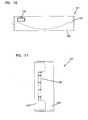
- the fiber optic enclosure 121is shown mounted to a mounting location 183 (e.g., wall, pole, etc.) in FIGS. 1 and 17 , it will be understood that the subscriber cable 122 can be paid out from the fiber optic enclosure 121 while the fiber optic enclosure 121 is either mounted to a mounting location 183 or removed from the mounting location 183. As shown in FIG. 18 , the subscriber cable 122 could be paid out while the fiber optic enclosure 121 is still packaged in a shipping container 179 provided there is an opening 181 in the shipping container 179 through which the subscriber cable 122 can be pulled. After the subscriber cable 122 has been paid out, the fiber optic enclosure 121 can be removed from the shipping container 179 and mounted to the mounting location 183.
- a mounting location 183e.g., wall, pole, etc.
Landscapes
- Physics & Mathematics (AREA)
- General Physics & Mathematics (AREA)
- Optics & Photonics (AREA)
- Light Guides In General And Applications Therefor (AREA)
- Storing, Repeated Paying-Out, And Re-Storing Of Elongated Articles (AREA)
- Insertion, Bundling And Securing Of Wires For Electric Apparatuses (AREA)
- Storage Of Web-Like Or Filamentary Materials (AREA)
- Unwinding Of Filamentary Materials (AREA)
Description
- The present disclosure relates to fiber optic enclosure, and more particularly, to a fiber optic enclosure with cable payout.
- As demand for telecommunications increases, fiber optic networks are being extended in more and more areas. In facilities such as multiple dwelling units, apartments, condominiums, businesses, etc., fiber optic enclosures are used to provide a subscriber access point to the fiber optic network. These fiber optic enclosures are connected to the fiber optic network through subscriber cables connected to a network hub. However, the length of subscriber cable needed between the fiber optic enclosure and the network hub varies depending upon the location of the fiber optic enclosure with respect to the network hub. As a result, there is a need for a fiber optic enclosure that can effectively manage varying lengths of subscriber cable.
- One prior art approach is disclosed in
US 6 220 413 , which shows a cable storage device which has a reel rotatably mounted in a frame. A connector panel for connecting fiber optic cables fits on the reel for rotation with the reel. When lines leading to an equipment are to be connected to the connector panel, the connector panel is moved to a docking station on the reel. - The present invention provides a fiber optic enclosure assembly for enclosing optical fiber connections according to
independent claim 1. Further, the present invention provides a method of paying out a fiber optic cable from a fiber optic enclosure according to independent claim 8. Further advantageous embodiments of the invention may be realised according to the corresponding dependent claims. - An exemplary device of the present disclosure relates to a fiber optic enclosure assembly for enclosing optical fiber connections. The fiber optic enclosure assembly includes a housing having an interior region and a bearing mount disposed in the interior region of the housing. A cable spool is connectedly engaged with the bearing mount such that the cable spool selectively rotates within the housing. A termination module is disposed on the cable spool so that the termination module rotates in unison with the cable spool.
- An exemplary method of the present disclosure relates to a method of paying out a fiber optic cable from a fiber optic enclosure. The method includes rotating a cable spool, which has a subscriber cable coiled around a spooling portion of the cable spool, about an axis of a housing of the fiber optic enclosure until a desired length of subscriber cable is paid out. The cable spool is disposed in an interior region of the fiber optic enclosure and a termination module is disposed on the cable spool.
FIG. 1 is a schematic representation of a fiber optic network that includes a fiber optic enclosure having features that are examples of inventive aspects in accordance with the principles of the present disclosure.FIG. 2 is an isometric view of the fiber optic enclosure ofFIG. 1 .FIG. 3 is an isometric view of the fiber optic enclosure ofFIG. 2 with a cover in an open position.FIG. 4 is a front view of the fiber optic enclosure ofFIG. 2 with the cover in the open position.FIG. 5 is an exploded isometric view of the fiber optic enclosure ofFIG. 2 .FIG. 6 is a perspective view of a fiber optic adapter suitable for use within the fiber optic enclosure ofFIG. 2 .FIG. 7 is a cross-sectional view of the fiber optic adapter taken on line 7-7 ofFIG. 6 .FIG. 8 is an isometric view of another embodiment of a fiber optic enclosure.FIG. 9 is a front view of the fiber optic enclosure ofFIG. 8 .FIG. 10 is a top view of the fiber optic enclosure ofFIG. 8 .FIG. 11 is a side view of the fiber optic enclosure ofFIG. 8 .FIG. 12 is an isometric view of the fiber optic enclosure ofFIG. 8 , showing cables entering and exiting the enclosure.FIG. 13 is an isometric view of the fiber optic enclosure ofFIG. 12 without the cover.FIG. 14 is a front view of the fiber optic enclosure ofFIG. 13 .FIG. 15 is an exploded isometric view of the fiber optic enclosure ofFIG. 13 .FIG. 16 is an isometric view of the cable spool of the fiber optic enclosure ofFIG. 13 .FIG. 17 is a further isometric view of the fiber optic enclosure ofFIG. 12 , with the cover in the pivoted open position.FIG. 18 is an exploded view of a shipping container in which is disposed the fiber optic enclosure ofFIG. 8 .- Reference will now be made in detail to the exemplary aspects of the present disclosure that are illustrated in the accompanying drawings. Wherever possible, the same reference numbers will be used throughout the drawings to refer to the same or like structure.
- Referring now to
FIG. 1 , a schematic representation of a fiber optic network, generally designated 11, in a facility 13 (e.g. individual residence, apartment, condominium, business, etc.) is shown. The fiberoptic network 11 includes afeeder cable 15 from a central office (not shown). Thefeeder cable 15 enters a feeder cable input location 17 (e.g., a fiber distribution hub, a network interface device, etc.) having one or more optical splitters (e.g., 1-to-8 splitters, 1-to-16 splitters, or 1-to-32 splitters) that generate a number of individual fibers. In the subject embodiment, and by way of example only, thefiber distribution hub 17 is located on alower level 19 of thefacility 13. Each unit in thefacility 13 includes a fiber optic enclosure, generally designated 21, with asubscriber cable 22 extending from each of the fiberoptic enclosures 21 to thefiber distribution hub 17. Thesubscriber cable 22 extending between thefiber distribution hub 17 and the fiberoptic enclosure 21 typically includes multiple optical fibers. - Referring now to
FIGS. 2-5 , the fiberoptic enclosure 21 will now be described. The fiberoptic enclosure 21 includes a housing, generally designated 23, having acover 25. - The
housing 23 includes abase 27, afirst sidewall 29, and an oppositely disposedsecond sidewall 31. The first andsecond sidewalls base 27 such that thebase 27 and the first andsecond sidewalls interior region 33. In the subject embodiment, thecover 25 is hingedly engaged with asidewall 35 that is connected to thebase 27 and the first andsecond sidewalls cover 25 being hingedly engaged thesidewall 35. - A cable spool, generally designated 37, is disposed in the
interior region 33 of the fiberoptic enclosure 21. Thecable spool 37 includes aspooling portion 39, around whichsubscriber cable 22 is coiled (shown schematically inFIG. 1 ). Thecable spool 37 further includes anaxial end 41. - In the subject embodiment, the
axial end 41 of thecable spool 37 defines a termination area 43 (shown as a dashed line inFIG. 5 ). Disposed in thetermination area 43 is a termination module, generally designated 45. Thetermination module 45 of the fiberoptic enclosure 21 serves as the dividing line between the incoming fibers and the outgoing fibers. - In the subject embodiment, the
termination module 45 includes anadapter plate 47. Theadapter plate 47 is an L-shaped bracket having a first side 49 (shown inFIG. 4 ) and asecond side 51. Thefirst side 49 defines a plurality of mountingholes 53 while thesecond side 51 defines anadapter slot 55. It will be understood, however, that the scope of the present disclosure is not limited to theadapter plate 47 being an L-shaped bracket. Thefirst side 49 of theadapter plate 47 is rigidly mounted (i.e., non-rotatable) to theaxial end 41 of thecable spool 37 through a plurality of fasteners 57 (e.g., bolts, screws, rivets, etc.) which are inserted through the mountingholes 53 in thefirst side 49 and in connected engagement with theaxial end 41 of thecable spool 37. - The
adapter slot 55 in thesecond side 51 of theadapter plate 47 is adapted to receive a plurality of adapters, generally designated 401. In the subject embodiment, theadapters 401 are SC-type adapters 401, although it will be understood that the scope of the present disclosure is not limited to the use of SC-type adapters 401. Similar SC-type adapters 401 have been described in detail in commonly ownedU.S. Pat. No. 5,317,663 . - Referring now to
FIGS. 6 and 7 , the SC-type adapter 401 includes amain body 403 with a pair oftabs main body 403. Thetabs adapter 401 in theadapter slot 55. Theadapter 401 further includes a pair of retainingclips retaining clip tab front side 413 of theadapter 401 is inserted into theadapter slot 55. As theadapter 401 is inserted through theadapter slot 55, the retainingclips main body 403. Theadapter 401 is inserted into theadapter slot 55 until thetabs adapter plate 47. With thetabs adapter plate 47, the retainingclips adapter plate 47, thereby retaining theadapter plate 47 between the retainingclips tabs - In an alternate embodiment, the termination module includes a plurality of sliding adapter modules. Similar sliding adapter modules have been described in detail in commonly owned
U.S. Pat. Nos. 5,497,444 ;5,717,810 ,6,591,051 andU.S. Pat. Pub. No. 2007/0025675 . - Referring now to
FIGS 3-5 , theaxial end 41 of thecable spool 37 further defines aslack storage area 59. Theslack storage area 59 includes acable management spool 61 disposed on theaxial end 41 of thecable spool 37. Thecable management spool 61 is sized such that an outer radius of thecable management spool 61 is larger than the minimum bend radius of the optical fibers so as to avoid attenuation damage to the optical fibers during storage. - The
cable management spool 61 and theaxial end 41 of thecable spool 37 cooperatively define acable passage 63 that extends axially through thecable management spool 61 and through theaxial end 41 of thecable spool 37. Thecable passage 63 allows connectorized ends of incoming optical fibers to pass from the spoolingportion 39 of thecable spool 37 to theslack storage area 59. The connectorized ends of the incoming optical fibers are then routed from theslack storage area 59 to thefront sides 413 of theadapters 401 in thetermination area 43. - Referring now to
FIG. 5 , thefiber optic enclosure 21 further includes a bearing mount, generally designated 71. In the subject embodiment, the bearingmount 71 is disposed on thebase 27 of thehousing 23. Anouter surface 73 of the bearingmount 71 is adapted for a bearing 75 (shown as cross-hatching). In the subject embodiment, thebearing 75 is a needle bearing. However, it will be understood that the scope of the present disclosure is not limited to thebearing 75 being a needle bearing as thebearing 75 could also include a bushing, low-friction coating, etc. - In one embodiment, the
bearing 75 is engaged with an inner diameter of a central hole of thecable spool 37. In another embodiment, a rotary plain bearing is formed between theouter surface 73 of the bearingmount 71 and the inner diameter of the central hole of thecable spool 37. In this embodiment, the outer diameter of the bearingmount 71 is sized to fit within an inner diameter of a central hole of the spoolingportion 39. The engagement of the bearingmount 71 and the spoolingportion 39 of thecable spool 37 allows thecable spool 37 to rotate about the central axis 77 of the bearingmount 71. - Referring now to
FIGS. 1 and5 , thesubscriber cable 22, which includes multiple optical fibers, is coiled around the spoolingportion 39 of thecable spool 37. In order to protect thesubscriber cable 22 from attenuation resulting from the coiling of thesubscriber cable 22 around the spoolingportion 39, thecable spool 37 has an outer circumferential surface having a radius that is greater than the minimum bend radius of thesubscriber cable 22. Thesubscriber cable 22 includes a first end having connectorized ends, which are inserted through thecable passage 63 and connectedly engaged with the first ends 413 of theadapters 401. A second end of thesubscriber cable 22 is configured for connectivity with thefiber distribution hub 17. However, as shown inFIG. 1 , the length ofsubscriber cable 22 needed between each of thefiber optic enclosures 21 in thefacility 13 and thefiber distribution hub 17 will vary depending upon the location of eachfiber optic enclosure 21 with respect to thefiber distribution hub 17. - A method of installing and using the
fiber optic enclosure 21 to account for the varying lengths ofsubscriber cable 22 needed between thefiber optic enclosure 21 and thefiber distribution hub 17 will now be described. Thefiber optic enclosure 21 provides dual functionality by serving as a storage location for thesubscriber cable 22 and by selectively paying out a desired length of thesubscriber cable 22. - A first length of
subscriber cable 22 is stored in thefiber optic enclosure 21 by coiling the length ofsubscriber cable 22 around thecable spool 37. The first length ofsubscriber cable 22 includes an installation length, which is sufficiently long to extend from the mounting location of the enclosure 28 to thefiber distribution hub 17, and an excess length; which is the length ofsubscriber cable 22 remaining on thecable spool 37 after the installation length has been paid out. In one embodiment, the first length is greater than or equal to about 100 feet. In another embodiment, the first length ofsubscriber cable 22 is greater than or equal to about 200 feet. In another embodiment, the first length ofsubscriber cable 22 is greater than or equal to about 300 feet. In another embodiment, the first length ofsubscriber cable 22 is greater than or equal to about 400 feet. In another embodiment, the first length ofsubscriber cable 22 is greater than or equal to about 500 feet. In another embodiment, the first length ofsubscriber cable 22 is in the range of about 100 to about 2,000 feet. In another embodiment, the first length ofsubscriber cable 22 is in the range of about 100 to about 1,500 feet. In another embodiment, the first length ofsubscriber cable 22 is in the range of about 500 to about 1,500 feet. In a preferred embodiment, the first length ofsubscriber cable 22, which is coiled around the cable spool 89, is in the range of 100 to 500 feet. - In one embodiment, a second length, or the excess length, of
subscriber cable 22 is stored around thecable spool 37 after the first length ofsubscriber cable 22 has been paid out. If the first length ofsubscriber cable 22 is greater than the installation length ofsubscriber cable 22, the second length, or excess length, is stored around thecable spool 37. - The second function of the
fiber optic enclosure 21 involves the selective payout of thesubscriber cable 22. With thecable spool 37 mounted to thebearing mount 71, the first end of thesubscriber cable 22 in connected engagement with thefront sides 413 of theadapters 401 and the outgoing optical fibers disengaged from the back sides of theadapters 401, thesubscriber cable 22 can be paid out throughfiber ports 79 disposed in the first andsecond sidewalls subscriber cable 22 is paid out of thefiber optic enclosure 21 by selectively rotating thecable spool 37 with respect to thehousing 23 about the central axis 77 of the bearingmount 71. As thetermination module 45 is disposed on theaxial end 41 of thecable spool 37, the selective rotation of thecable spool 37 with respect to thehousing 23 results in the selective rotation of thetermination module 45. Since thetermination module 45 rotates unitarily with or in unison with thecable spool 37, the second end of thesubscriber cable 22 can be paid out without the first end of thesubscriber cable 22 being pulled out of thetermination module 45. - Once the desired length of
subscriber cable 22 has been paid out, the rotation of thecable spool 37 is ceased. At this point, the position of thecable spool 37 can be fixed such that it does not rotate relative to thehousing 23. In one embodiment, a pin is inserted through an opening in theaxial end 41 of thecable spool 37 and through a corresponding opening in thebase 27 of thehousing 23 to fix the position of thecable spool 37 with respect to thehousing 23. It will be understood, however, that the scope of the present disclosure is not limited to the use of a pin to fix the position of thecable spool 37 with respect tohousing 23. - An alternate method of selectively paying-out
subscriber cable 22 from thefiber optic enclosure 21 will now be described. With thefiber optic enclosure 21 positioned near thefiber distribution hub 17, the second end of thesubscriber cable 22 is unwound from thecable spool 37. In one embodiment, the second end is optically connected to thefiber distribution hub 17. With the second end of thesubscriber cable 22 optically connected to thefiber distribution hub 17 and the first end of thesubscriber cable 22 in connected engagement with thetermination module 45, thefiber optic enclosure 21 is transported away from thefiber distribution hub 17. In one embodiment, thefiber optic enclosure 21 is carried away from thefiber distribution hub 17 by an installer. In another embodiment, thefiber optic enclosure 21 is transported away from thefiber distribution hub 17 in a wheeled cart (e.g., dolly, 4-wheeled cart, etc.). In a preferred embodiment, the fiber optic enclosure is disposed in a packaging enclosure (e.g., a box) during transport. As thefiber optic enclosure 21 is transported away from thefiber distribution hub 17, thesubscriber cable 22 unwinds from thecable spool 37 causing thecable spool 37 to rotate within theinterior region 33 of thehousing 23, which is disposed in the packaging enclosure. When thefiber optic enclosure 21 has been transported to its mounting location, thefiber optic enclosure 21 is removed from the packaging enclosure, mounted to the mounting location. Thecable spool 37 can be fixed in position relative to thehousing 23 to prevent inadvertent rotation of thecable spool 37. - Referring now to
FIGS. 8-18 , an alternate embodiment of afiber optic enclosure 121 is shown. Thefiber optic enclosure 121 includes ahousing 123 and a hingedcover 125. - The
housing 123 includes abase wall 120, afirst sidewall 127 and an oppositely disposedsecond sidewall 128. The first andsecond sidewalls base wall 120 such that thebase wall 120 and the first andsecond sidewalls - In the subject embodiment, the
first sidewall 127 of thehousing 123 defines afirst port 131 while thesecond sidewall 128 defines asecond port 132. Thesubscriber cable 122 enters/exits thefiber optic enclosure 121 at thefirst port 131 or at thesecond port 132. In the subject embodiment, both of the first andsecond ports - A
cable spool 137 is positioned within the interior region 130 ofenclosure 121. In the subject embodiment, thecable spool 137 is adapted for rotation within the interior region 130 of theenclosure 121. In the subject embodiment, thecable spool 137 includes a firstaxial end 136, an oppositely disposed secondaxial end 138 and aspool portion 139. Thespool portion 139 is disposed between the first and second axial ends 136, 138 of thecable spool 137. Thespool portion 139 is adapted to receive asubscriber cable 122 coiled around or spooled on thespool portion 139. - With the
subscriber cable 122 spooled on thespool portion 139, thesubscriber cable 122 can be selectively paid out by rotating thecable spool 137. As thecable spool 137 is rotated, thesubscriber cable 122 is unwound from thespool portion 139 of thecable spool 137. After a desired length ofsubscriber cable 122 has been paid out, pinopenings 141 can be used with a pin to fix the position ofcable spool 137 relative tohousing 123. - The
subscriber cable 122 is shown with a connectorized end 144 (e.g., MTP connector) for connecting to thefiber distribution hub 17 or other equipment. An opposite end of thesubscriber cable 122 passes through anopening 145 disposed in the firstaxial end 136 of thecable spool 137. After passing through theopening 145, thesubscriber cable 122 is routed to afanout 147 disposed on the firstaxial end 136 of thecable spool 137 where the cable is broken out intoindividual fibers 124 having connectorized ends 146 (e.g., SC connectors). - A
cable management spool 161 is also disposed on the firstaxial end 136 of thecable spool 137. Thecable management spool 161 managesfibers 124. In the subject embodiment, thecable management spool 161 includes a plurality offingers 162 disposed on an end of thecable management spool 161. Thefingers 162 assist with cable retention. - The first
axial end 136 of thecable spool 137 further includes anouter guide wall 163. In the subject embodiment, theouter guide wall 163 is disposed at a portion of the peripheral edge of the firstaxial end 136 adjacent to thecable management spool 161. In the subject embodiment, theouter guide wall 163 extends outwardly in a direction that is generally perpendicular to the firstaxial end 136. - The
outer guide wall 163 includes with acable finger 164 disposed at an end of theouter guide wall 163 that is opposite the end engaged with the firstaxial end 136 of thecable spool 137. Thecable finger 164 assists with retention and protection of thefibers 124. - An
adapter plate 149 is disposed on the firstaxial end 136 of thecable spool 137. In the subject embodiment, theadapter plate 149 includesseparate openings 151. Each of theseparate openings 151 is adapted to receive twoadapters 401. - In the depicted embodiment of
FIG. 16 , thecable management spool 161, theouter guide wall 163 and theadapter plate 149 are integrally formed with the firstaxial end 136 of thecable spool 137. In the subject embodiment, the firstaxial end 136 of thecable spool 137 is formed from plastic. In another embodiment, the first and second axial ends 136, 138, thespool portion 139, theadapter plate 149, thecable management spool 161 and theouter guide wall 163 are integrally formed from a plastic material. - Referring now to
FIGS. 13 and14 , thefiber optic enclosure 121 is shown connected to asecond subscriber cable 126. After thesubscriber cable 122 is paid out andcable spool 137 fixed in position relative to thehousing 123, individual connectorized ends of thesecond subscriber cables 126 can be connected to thefibers 124 atadapters 401 ofadapter plate 149. Thesecond subscriber cables 126 exit thefiber optic enclosure 121 at aport 136 in a side 165 of thehousing 123. In the illustrated embodiment, a slottedfoam member 138 is disposed in theport 136. The slottedfoam member 138 includes a plurality of slots through which thesecond subscriber cables 126 can be inserted in order to prevent or reduce the risk of ingress of environmental contamination (e.g., dust, water, etc.). - While the
fiber optic enclosure 121 is shown mounted to a mounting location 183 (e.g., wall, pole, etc.) inFIGS. 1 and17 , it will be understood that thesubscriber cable 122 can be paid out from thefiber optic enclosure 121 while thefiber optic enclosure 121 is either mounted to a mounting location 183 or removed from the mounting location 183. As shown inFIG. 18 , thesubscriber cable 122 could be paid out while thefiber optic enclosure 121 is still packaged in ashipping container 179 provided there is anopening 181 in theshipping container 179 through which thesubscriber cable 122 can be pulled. After thesubscriber cable 122 has been paid out, thefiber optic enclosure 121 can be removed from theshipping container 179 and mounted to the mounting location 183.
Claims (14)
- A fiber optic enclosure assembly for enclosing optical fiber connections comprising:a housing (23; 123) having an interior region (33; 130);a bearing mount (71) disposed in the interior region (33; 130) of the housing (23; 123);a cable spool (37; 137) engaged with the bearing mount (71) such that the cable spool (37; 137) selectively rotates within the housing (23; 123);a termination module (45; 149) disposed on the cable spool (37; 137) so that the termination module (45; 149) rotates in unison with the cable spool (37; 137);a first fiber optic cable (22; 122) wrapped about a spooling portion of the cable spool (37; 137), the first fiber optic cable (22; 122) having connectorized ends (146) that are routed to the termination module (45; 149); andfixing means to fix the position of the cable spool (37; 137) with respect to the housing (23; 123);characterized in that the housing (23; 123) includes a port (136) wherein a second fiber optic cable having connectorized ends can be connected to the termination module (45; 149) in the interior region (33; 130) of the housing (23; 123) and exits the housing via the port, after the cable spool (37; 137) has been fixed in position relative to the housing (23; 123).
- A fiber optic enclosure assembly as claimed in claim 1, wherein a needle bearing is disposed on an outer surface (73) of the bearing mount (71).
- A fiber optic enclosure assembly as claimed in claim 1, wherein the termination module (45; 149) includes an adapter plate (47; 149) having an adapter slot (55) with a plurality of adapters (401) engaged with the adapter slot (55).
- A fiber optic enclosure assembly as claimed in claim 1, wherein the termination module (45; 149) includes a plurality of sliding adapter modules.
- A fiber optic enclosure assembly as claimed in claim 1, wherein the axial end (41; 136) of the cable spool (37; 137) defines a cable passage (63).
- A fiber optic enclosure assembly as claimed in claim 1, wherein the fiber optic enclosure assembly further comprises a cable manager that is a cable management spool (61; 161).
- A fiber optic enclosure assembly as claimed in claim 1, wherein the fiber optic enclosure assembly further comprises a cable manager that includes an outer radius that is larger than a minimum bend radius of the fiber optic cable.
- A method of paying out a fiber optic cable from a fiber optic enclosure, comprising:providing a fiber optic enclosure including:a housing (23; 123) defining an interior region (33; 130);a cable spool (37; 137) disposed in the interior region (33; 130), the cable spool (37; 137) having a spooling portion (39);a termination module (45; 149) disposed on the cable spool (37; 137);a first fiber optic cable (22; 122) coiled around the spooling portion (39) of the cable spool (37; 137), the first fiber optic cable (22; 122) including connectorized ends (146) that are engaged with the termination module (45; 149);and fixing means to fix the position of the cable spool (37; 137) with respect to the housing (23, 123):rotating the cable spool (37; 137) about an axis of the housing (23; 123) of the fiber optic enclosure until a desired length of the first fiber optic cable (22; 122) is paid out;characterized byfixing the position of the cable spool (37; 137) with respect to the housing (23; 123) when a desired length of the first fiber optic cable (22; 122) has been paid out;connecting a connectorized end of a second fiber optic cable to the termination module (45; 149) in the interior region (33; 130) of the fiber optic enclosure after the fixing has been carried out.
- A method of paying out a fiber optic cable from a fiber optic enclosure as claimed in claim 8, wherein the termination module (45; 149) includes a plurality of adapters (401).
- A method of paying out a fiber optic cable from a fiber optic enclosure as claimed in claim 9, wherein the termination module (45; 149) includes an adapter plate (47; 149) having an adapter slot (55) with the plurality of adapters (401) engaged with the adapter slot (55).
- A method of paying out a fiber optic cable from a fiber optic enclosure as claimed in claim 9, where the termination module (45; 149) includes a plurality of sliding adapter modules.
- A method of paying out a fiber optic cable from a fiber optic enclosure as claimed in claim 8, wherein the connectorized ends (146) of a first end of the first fiber optic cable (22; 122) are connected to adapters (401) disposed in the termination module (45; 149).
- A method of paying out a fiber optic cable from a fiber optic enclosure as claimed in claim 8, wherein the housing (23; 123) is mounted to a wall.
- A method of paying out a fiber optic cable from a fiber optic enclosure as claimed in claim 8, wherein a pin fixes the position of the cable spool (37; 137) with respect to the housing (23; 123).
Priority Applications (4)
| Application Number | Priority Date | Filing Date | Title |
|---|---|---|---|
| EP15182271.5AEP2963469B1 (en) | 2007-08-06 | 2008-08-05 | Fiber optic enclosure with internal cable spool |
| DK13163032.9TDK2618195T3 (en) | 2007-08-06 | 2008-08-05 | Method for unwinding a fiber optic cable from a fiber optic housing with internal cable coil |
| PL13163032TPL2618195T3 (en) | 2007-08-06 | 2008-08-05 | Method of paying out a fiber optic cable from a fiber optic enclosure with internal cable spool |
| EP13163032.9AEP2618195B1 (en) | 2007-08-06 | 2008-08-05 | Method of paying out a fiber optic cable from a fiber optic enclosure with internal cable spool |
Applications Claiming Priority (4)
| Application Number | Priority Date | Filing Date | Title |
|---|---|---|---|
| US95421407P | 2007-08-06 | 2007-08-06 | |
| US2924808P | 2008-02-15 | 2008-02-15 | |
| US12/182,705US7756379B2 (en) | 2007-08-06 | 2008-07-30 | Fiber optic enclosure with internal cable spool |
| PCT/US2008/072218WO2009048680A1 (en) | 2007-08-06 | 2008-08-05 | Fiber optic enclosure with internal cable spool |
Related Child Applications (3)
| Application Number | Title | Priority Date | Filing Date |
|---|---|---|---|
| EP13163032.9ADivisionEP2618195B1 (en) | 2007-08-06 | 2008-08-05 | Method of paying out a fiber optic cable from a fiber optic enclosure with internal cable spool |
| EP13163032.9ADivision-IntoEP2618195B1 (en) | 2007-08-06 | 2008-08-05 | Method of paying out a fiber optic cable from a fiber optic enclosure with internal cable spool |
| EP15182271.5ADivisionEP2963469B1 (en) | 2007-08-06 | 2008-08-05 | Fiber optic enclosure with internal cable spool |
Publications (2)
| Publication Number | Publication Date |
|---|---|
| EP2176696A1 EP2176696A1 (en) | 2010-04-21 |
| EP2176696B1true EP2176696B1 (en) | 2014-04-23 |
Family
ID=40454555
Family Applications (3)
| Application Number | Title | Priority Date | Filing Date |
|---|---|---|---|
| EP13163032.9AActiveEP2618195B1 (en) | 2007-08-06 | 2008-08-05 | Method of paying out a fiber optic cable from a fiber optic enclosure with internal cable spool |
| EP15182271.5AActiveEP2963469B1 (en) | 2007-08-06 | 2008-08-05 | Fiber optic enclosure with internal cable spool |
| EP08837186.9AActiveEP2176696B1 (en) | 2007-08-06 | 2008-08-05 | Fiber optic enclosure with internal cable spool |
Family Applications Before (2)
| Application Number | Title | Priority Date | Filing Date |
|---|---|---|---|
| EP13163032.9AActiveEP2618195B1 (en) | 2007-08-06 | 2008-08-05 | Method of paying out a fiber optic cable from a fiber optic enclosure with internal cable spool |
| EP15182271.5AActiveEP2963469B1 (en) | 2007-08-06 | 2008-08-05 | Fiber optic enclosure with internal cable spool |
Country Status (14)
| Country | Link |
|---|---|
| US (21) | US7756379B2 (en) |
| EP (3) | EP2618195B1 (en) |
| CN (2) | CN101802672B (en) |
| AR (1) | AR067819A1 (en) |
| BR (1) | BRPI0815601B1 (en) |
| DK (1) | DK2618195T3 (en) |
| ES (2) | ES2558172T3 (en) |
| HR (1) | HRP20151415T1 (en) |
| HU (1) | HUE028611T2 (en) |
| MX (1) | MX2010001388A (en) |
| PL (1) | PL2618195T3 (en) |
| PT (1) | PT2618195E (en) |
| TW (1) | TWI452372B (en) |
| WO (1) | WO2009048680A1 (en) |
Families Citing this family (140)
| Publication number | Priority date | Publication date | Assignee | Title |
|---|---|---|---|---|
| US7400814B1 (en) | 2007-01-13 | 2008-07-15 | Furukawa Electric North America, Inc. | Wall-mountable optical fiber and cable management apparatus |
| US7715679B2 (en) | 2007-05-07 | 2010-05-11 | Adc Telecommunications, Inc. | Fiber optic enclosure with external cable spool |
| US7748660B2 (en)* | 2007-06-22 | 2010-07-06 | Ofs Fitel, Llc | Fiber optic rapid spooling tool |
| US7756379B2 (en)* | 2007-08-06 | 2010-07-13 | Adc Telecommunications, Inc. | Fiber optic enclosure with internal cable spool |
| US7869682B2 (en) | 2007-09-05 | 2011-01-11 | Adc Telecommunications, Inc. | Fiber optic enclosure with tear-away spool |
| US8798427B2 (en) | 2007-09-05 | 2014-08-05 | Corning Cable Systems Llc | Fiber optic terminal assembly |
| EP2285546A4 (en)* | 2008-05-27 | 2014-03-12 | Adc Telecommunications Inc | SYSTEMS, METHODS AND TOOLS FOR MOLDING FLEXIBLE EXTRUDED CABLES |
| US8254740B2 (en) | 2008-06-19 | 2012-08-28 | Adc Telecommunications, Inc. | Methods and systems for distributing fiber optic telecommunications services to local area |
| CN102209921B (en) | 2008-10-09 | 2015-11-25 | 康宁光缆系统有限公司 | There is the fibre-optic terminus supported from the adapter panel of the input and output optical fiber of optical splitters |
| US8879882B2 (en) | 2008-10-27 | 2014-11-04 | Corning Cable Systems Llc | Variably configurable and modular local convergence point |
| US7738758B1 (en)* | 2008-12-10 | 2010-06-15 | Verizon Patent And Licensing Inc. | Compact optical splitter module |
| US20100142888A1 (en)* | 2008-12-10 | 2010-06-10 | Verizon Corporate Resources Group Llc | Compact fiber distribution hub |
| US8903215B2 (en) | 2008-12-31 | 2014-12-02 | Opterna Technology Limited | Enclosure-less fiber optic terminals |
| US8081857B2 (en)* | 2008-12-31 | 2011-12-20 | Opterna Am, Inc. | System for an internal rotating storage spool combined with top and bottom cable access in a fiber distribution terminal |
| AU329420S (en)* | 2009-06-05 | 2010-01-29 | Sumitomo Electric Industries | Optical fiber holder |
| EP2264502B1 (en)* | 2009-06-19 | 2013-03-13 | Nexans | Method of connecting optical fibres |
| KR101820175B1 (en)* | 2009-07-21 | 2018-01-18 | 콤스코프 커넥티비티 엘엘씨 | Rapid universal rack mount enclosure |
| AU2015200424C1 (en)* | 2009-07-21 | 2017-03-16 | Commscope Technologies Llc | Rapid universal rack mount enclosure |
| US8238707B2 (en) | 2009-07-30 | 2012-08-07 | Adc Telecommunications, Inc. | Locking spool for telecommunications cable and method |
| US8474742B2 (en)* | 2009-07-30 | 2013-07-02 | Adc Telecommunications, Inc. | Spool for telecommunications cable and method |
| CA2770281C (en)* | 2009-08-06 | 2018-02-13 | 3M Innovative Properties Company | System and method for providing final drop in a living unit in a building |
| US8428419B2 (en)* | 2009-09-23 | 2013-04-23 | Adc Telecommunications, Inc. | Fiber distribution hub with internal cable spool |
| US8515234B2 (en)* | 2009-11-25 | 2013-08-20 | Adc Telecommunications, Inc. | Methods, systems and devices for providing fiber-to-the-desktop |
| WO2011076275A1 (en)* | 2009-12-23 | 2011-06-30 | Prysmian S.P.A. | Optical termination assembly |
| EP2545402B1 (en) | 2010-03-11 | 2018-05-23 | ADC Telecommunications, Inc. | Fiber optic enclosure with internal cable spool assembly |
| US9547144B2 (en) | 2010-03-16 | 2017-01-17 | Corning Optical Communications LLC | Fiber optic distribution network for multiple dwelling units |
| US9078287B2 (en) | 2010-04-14 | 2015-07-07 | Adc Telecommunications, Inc. | Fiber to the antenna |
| US8837940B2 (en) | 2010-04-14 | 2014-09-16 | Adc Telecommunications, Inc. | Methods and systems for distributing fiber optic telecommunication services to local areas and for supporting distributed antenna systems |
| US8792767B2 (en) | 2010-04-16 | 2014-07-29 | Ccs Technology, Inc. | Distribution device |
| AU2014274625B2 (en)* | 2010-06-18 | 2016-05-26 | Adc Communications (Shanghai) Co., Ltd. | Fiber opitic distribution terminal and method of deploying fiber distribution cable |
| AU2010355632B2 (en)* | 2010-06-18 | 2014-09-18 | Adc Communications (Shanghai) Co., Ltd. | Fiber optic distribution terminal and method of deploying fiber distribution cable |
| CN110174737A (en) | 2010-06-23 | 2019-08-27 | Adc电信公司 | Telecommunication assembly |
| AU2015202664B2 (en)* | 2010-06-23 | 2016-10-20 | Commscope Technologies Llc | Telecommunications assembly |
| US8792766B2 (en)* | 2010-07-20 | 2014-07-29 | Ofs Fitel, Llc | Tool for routing an optical fiber or cable at a living unit of customer premises |
| EP2567271B1 (en)* | 2010-07-20 | 2016-10-12 | Ofs Fitel Llc | Optical fiber installation at customer premises |
| WO2012018787A2 (en) | 2010-08-02 | 2012-02-09 | Adc Telecommunications, Inc. | Cable spool assembly |
| CN102346285B (en)* | 2010-08-04 | 2013-04-10 | 昆山市大唐通讯设备有限公司 | FTTB multipurpose integration information box |
| WO2012054454A2 (en)* | 2010-10-19 | 2012-04-26 | Corning Cable Systems Llc | Transition box for multiple dwelling unit fiber optic distribution network |
| CA2814954A1 (en) | 2010-10-19 | 2012-04-26 | Corning Cable Systems Llc | Collapsible cable reel |
| US8873922B2 (en) | 2010-12-20 | 2014-10-28 | Adc Telecommunications, Inc. | Fan-out and parking module |
| EP2671111B1 (en) | 2011-02-01 | 2018-11-07 | Opterna Technology Limiited | Fiber distribution hubs |
| US8720810B2 (en) | 2011-02-11 | 2014-05-13 | Adc Telecommunications, Inc. | Spool for telecommunications cable and method |
| CA2834781C (en) | 2011-05-13 | 2019-02-05 | Corning Cable Systems Llc | Transformable cable reels and related assemblies and methods |
| ITMI20110958A1 (en)* | 2011-05-26 | 2012-11-27 | Adb Broadband Spa | TERMINAL SYSTEM FOR FIBER OPTIC NETWORK |
| CA2877896C (en) | 2011-06-24 | 2020-07-21 | Adc Telecommunications, Inc. | Fiber termination enclosure with modular plate assemblies |
| WO2013039783A2 (en)* | 2011-09-16 | 2013-03-21 | Adc Telecommunciations, Inc. | Fiber optic cable packaging management |
| US8886005B2 (en) | 2012-02-13 | 2014-11-11 | Opterna Technology Limited | Adapter retaining systems |
| US8913867B2 (en) | 2011-11-21 | 2014-12-16 | Opterna Technology Limited | Fiber optic collector and terminal assemblies |
| WO2013078322A2 (en)* | 2011-11-21 | 2013-05-30 | Opterna Am, Inc. | Enclosure-less fiber optic terminals and adapter retaining systems |
| US9219546B2 (en) | 2011-12-12 | 2015-12-22 | Corning Optical Communications LLC | Extremely high frequency (EHF) distributed antenna systems, and related components and methods |
| US9188760B2 (en) | 2011-12-22 | 2015-11-17 | Adc Telecommunications, Inc. | Mini rapid delivery spool |
| KR101285334B1 (en)* | 2012-01-06 | 2013-07-11 | 주식회사 에이제이월드 | A fiber optic cable connecting terminal box |
| US9329352B2 (en) | 2012-01-12 | 2016-05-03 | Corning Cable Systems Llc | Slack cable storage apparatus |
| US9036974B2 (en) | 2012-01-19 | 2015-05-19 | Adc Telecommunications, Inc. | Fiber optic enclosure with tear-away spool |
| US9494757B2 (en)* | 2012-02-29 | 2016-11-15 | Commscope Technologies Llc | Fiber optic cable packaging arrangement |
| US10110307B2 (en) | 2012-03-02 | 2018-10-23 | Corning Optical Communications LLC | Optical network units (ONUs) for high bandwidth connectivity, and related components and methods |
| WO2013165899A1 (en) | 2012-04-30 | 2013-11-07 | Adc Telecommunications, Inc. | Cable payout cassette with single layer cable storage area |
| US9722407B2 (en) | 2012-04-30 | 2017-08-01 | Commscope Technologies Llc | Guided cable storage assembly with switchbacks |
| US9126802B2 (en) | 2012-04-30 | 2015-09-08 | Adc Telecommunications, Inc. | Payout spool with automatic cable disconnect/reconnect |
| CN104412475B (en) | 2012-04-30 | 2019-01-15 | Adc电信公司 | Cable storage spool with center feed |
| USD709286S1 (en)* | 2012-05-01 | 2014-07-22 | SEI Optrifrontier Co., Ltd. | Carrying case for an optical fiber fusion splicer |
| CN103383484B (en)* | 2012-05-03 | 2015-04-15 | 泰科电子(上海)有限公司 | Fiber optical splice closure |
| US9004778B2 (en) | 2012-06-29 | 2015-04-14 | Corning Cable Systems Llc | Indexable optical fiber connectors and optical fiber connector arrays |
| CN106707434B (en)* | 2012-08-07 | 2019-06-11 | 爱德奇电讯国际贸易(上海)有限公司 | Fibre junction component |
| US9049500B2 (en) | 2012-08-31 | 2015-06-02 | Corning Cable Systems Llc | Fiber optic terminals, systems, and methods for network service management |
| US8909019B2 (en) | 2012-10-11 | 2014-12-09 | Ccs Technology, Inc. | System comprising a plurality of distribution devices and distribution device |
| EP2917775B1 (en) | 2012-11-07 | 2019-06-05 | CommScope Connectivity Belgium BVBA | Cable over-length storage system |
| WO2014072368A1 (en) | 2012-11-07 | 2014-05-15 | Tyco Electronics Raychem Bvba | Rapid distribution terminal |
| EP2741435A1 (en)* | 2012-12-04 | 2014-06-11 | 3M Innovative Properties Company | Fibre-optic Enclosure |
| ES1141660Y (en) | 2012-12-19 | 2015-10-14 | Tyco Electronics Raychem Bvba | Distribution device with incrementally added dividers |
| US10276990B2 (en)* | 2013-03-13 | 2019-04-30 | Commscope Technologies Llc | Telecommunications assembly with patch cord storage |
| US9344776B2 (en) | 2013-05-29 | 2016-05-17 | Go!Foton Holdings, Inc. | Patch panel tray assembly |
| JP6012565B2 (en)* | 2013-08-29 | 2016-10-25 | ヒロセ電機株式会社 | Photoelectric composite connector |
| US20150093088A1 (en)* | 2013-09-30 | 2015-04-02 | Optema Technology Limited | Fiber Optic Terminal Assemblies |
| WO2015067645A1 (en) | 2013-11-06 | 2015-05-14 | Adc Czech Republic, S.R.O. | Fiber termination point with overlength storage |
| US9366838B2 (en)* | 2013-11-19 | 2016-06-14 | Corning Cable Systems Llc | Secure cable housing system for optical communication network |
| FR3019313A1 (en)* | 2014-03-27 | 2015-10-02 | Orange | OPTICAL SOCKET WITH PRECONNECTED CABLE FEEDER |
| US10203465B2 (en)* | 2014-04-25 | 2019-02-12 | Commscope Technologies Llc | Managed connectivity in cable spool assemblies |
| EP2955802B1 (en)* | 2014-06-13 | 2018-08-08 | Textron Innovations Inc. | Cable feeder |
| US9429729B2 (en)* | 2014-08-04 | 2016-08-30 | Ofs Fitel, Llc | Compact storage and distribution module for optical fiber and cable |
| US10509187B2 (en) | 2014-09-23 | 2019-12-17 | Ppc Broadband, Inc. | Universal multi-purpose compartmentalized telecommunications box |
| US9882362B2 (en) | 2014-09-23 | 2018-01-30 | Ppc Broadband, Inc. | Enclosure for controling access to different telecommunication components |
| WO2016049242A1 (en) | 2014-09-23 | 2016-03-31 | Ppc Broadband, Inc. | Universal multi-purpose compartmentalized telecommunications box |
| US10976512B2 (en) | 2014-09-23 | 2021-04-13 | Ppc Broadband, Inc. | House box with mounting surface for mounted access |
| CA2971584C (en)* | 2014-12-19 | 2023-08-01 | 3M Innovative Properties Company | Ruggedized optical fiber connection structures and assemblies |
| US9612416B2 (en) | 2014-12-31 | 2017-04-04 | All Systems Broadband, Inc. | Fiber demarcation box for layering and storing coiled fiber optic cabling |
| BR112017017259A2 (en) | 2015-02-18 | 2018-04-17 | Adc Communications | fast scrolling indexing terminal layout |
| US9411119B1 (en) | 2015-03-02 | 2016-08-09 | Fluke Corporation | Carrying case for an optical launch fiber assembly |
| WO2016154092A1 (en)* | 2015-03-23 | 2016-09-29 | Commscope Technologies Llc | Fiber optic module and chassis with cable slack management |
| US10754115B2 (en) | 2015-04-22 | 2020-08-25 | CommScope Connectivity Belgium BVBA | Deploying optical fibers within a multi-dwelling unit |
| US10782499B2 (en)* | 2015-04-22 | 2020-09-22 | CommScope Connectivity Belgium BVBA | Cable storage arrangement |
| US9851523B2 (en) | 2015-09-22 | 2017-12-26 | Go!Foton Holdings, Inc. | Apparatus for cable routing |
| US10228527B2 (en) | 2015-09-25 | 2019-03-12 | Raytheon Company | Gimbal transmission cable management |
| US10495835B2 (en) | 2015-09-28 | 2019-12-03 | Commscope Technologies Llc | Fiber optic cable spool |
| US9470867B1 (en) | 2015-10-08 | 2016-10-18 | Primex Manufacturing Ltd. | Retaining enclosure for above-ground fiber optic/cable network terminal |
| CN105278043B (en)* | 2015-11-04 | 2017-01-25 | 南京普天天纪楼宇智能有限公司 | Jumper-connection-free fiber storage type optical fiber socket |
| EP3408701B1 (en)* | 2016-01-28 | 2023-04-26 | CommScope Connectivity Belgium BVBA | Modular telecommunications enclosure |
| AU2017217511A1 (en)* | 2016-02-08 | 2018-07-05 | Commscope Technologies Llc | Cable slack storage system for terminal |
| BR112018013502A2 (en)* | 2016-02-08 | 2018-12-04 | Commscope Technologies Llc | fiber demarcation point and clearance storage |
| US10788641B2 (en) | 2016-02-12 | 2020-09-29 | Ppc Broadband, Inc. | Cable spool and storage |
| US10076054B2 (en)* | 2016-03-31 | 2018-09-11 | Cisco Technology, Inc. | Adjustable cable management for fiber and cable |
| US10359590B2 (en) | 2016-04-04 | 2019-07-23 | Opterna Technology Limited | Fiber optic cable deployment assemblies, systems, and methods |
| WO2017189372A1 (en) | 2016-04-28 | 2017-11-02 | Commscope, Inc. Of North Carolina | Cable blowing apparatus and method |
| US9841574B1 (en)* | 2016-06-08 | 2017-12-12 | Belden Canada Inc. | Deformable latch mechanism for tray |
| US11073670B2 (en)* | 2016-08-12 | 2021-07-27 | Corning Optical Communications LLC | Device and method for sealing multiport splitters |
| US10606006B2 (en) | 2016-09-20 | 2020-03-31 | Clearfield, Inc. | Optical fiber distribution systems and components |
| US10859781B2 (en) | 2016-09-20 | 2020-12-08 | Clearfield, Inc. | Optical fiber distribution systems and components |
| US20180120526A1 (en)* | 2016-10-31 | 2018-05-03 | Clearfield, Inc. | Optical Fiber Enclosure |
| US10488612B2 (en) | 2016-11-07 | 2019-11-26 | Corning Optical Communications LLC | Fiber optic spool drawer with translatable and/or removable drawer for deployment of fiber optic cable |
| US10481360B2 (en) | 2016-11-16 | 2019-11-19 | Commscope Technologies Llc | Telecommunications cabling system |
| US10291969B2 (en) | 2017-02-14 | 2019-05-14 | Go!Foton Holdings, Inc. | Rear cable management |
| CN107037553A (en)* | 2017-05-17 | 2017-08-11 | 国网山东省电力公司威海供电公司 | A rack-mounted fiber optic cable jumper storage box |
| US10684437B2 (en)* | 2017-05-22 | 2020-06-16 | Steven E. Kaplan | Fiber optical terminal cross connect closure |
| US10310206B2 (en) | 2017-05-22 | 2019-06-04 | Go!Foton Holdings, Inc. | Apparatus for cable routing |
| US10634864B2 (en) | 2017-05-30 | 2020-04-28 | Panduit Corp. | Channel equalization enclosure |
| JP7033448B2 (en)* | 2017-12-22 | 2022-03-10 | 大電株式会社 | Fiber optic turnout |
| USD896191S1 (en)* | 2018-02-11 | 2020-09-15 | Fiberstore Co., Limited | Passive multiplexer |
| US11169344B2 (en)* | 2018-02-27 | 2021-11-09 | Commscope Technologies Llc | Common module storage within a fiber distribution hub |
| US11852882B2 (en) | 2018-02-28 | 2023-12-26 | Commscope Technologies Llc | Packaging assembly for telecommunications equipment |
| USD886752S1 (en)* | 2018-07-05 | 2020-06-09 | Fiberstore Co., Limited | Passive multiplexer |
| CN110713071B (en)* | 2018-08-08 | 2021-09-21 | 杭州富通通信技术股份有限公司 | Slitting equipment for prefabricated tail fiber manufacturing process |
| US10962730B2 (en)* | 2018-12-28 | 2021-03-30 | Clearfield, Inc. | Fiber optic panel with moveable cable support assembly and cable-windable support rods |
| TWI853904B (en)* | 2019-03-21 | 2024-09-01 | 美商Ppc寬頻股份有限公司 | Multi-fiber reel and adapter assembly |
| WO2020210479A1 (en) | 2019-04-12 | 2020-10-15 | Commscope Technologies Llc | Fiber optic spool arrangement; and method |
| US11745974B2 (en)* | 2019-05-10 | 2023-09-05 | Commscope Technologies Llc | Wound cable holder with improved cable deployment control |
| US12360327B2 (en) | 2019-10-17 | 2025-07-15 | Commscope Technologies Llc | Rack mounted enclosure |
| CA3159108A1 (en) | 2019-10-28 | 2021-12-23 | Opterna Am, Inc. | Terminal system assemblies with breakout/adapter modules |
| US11422326B2 (en)* | 2020-01-21 | 2022-08-23 | Clearfield, Inc. | Backplate for an optical fiber enclosure |
| US11567280B2 (en)* | 2020-01-23 | 2023-01-31 | Optical Cable Corporation | Splice sleeve holder nest |
| US10998703B1 (en)* | 2020-02-26 | 2021-05-04 | International Business Machines Corporation | Cable routing and bend radius defining tool |
| CN111352196B (en)* | 2020-02-28 | 2025-09-05 | 华为技术有限公司 | Optical cable fiber splitting device |
| EP3971622A1 (en) | 2020-07-02 | 2022-03-23 | Go!Foton Holdings, Inc. | Intelligent optical switch |
| WO2022036219A1 (en)* | 2020-08-14 | 2022-02-17 | Commscope Technologies Llc | Fiber optic enclosure with a side cable entrance |
| RU2766195C1 (en)* | 2020-09-28 | 2022-02-09 | Акционерное Общество "Институт "Оргэнергострой" | Container apparatus for assembling the linear part with combined interferometers for a fibre-optic security detector |
| EP4086679A1 (en)* | 2021-05-07 | 2022-11-09 | Triarca A/S | Pre-spliced optical fiber cables |
| EP4095579A1 (en) | 2021-05-28 | 2022-11-30 | Dkt A/S | A kit for installing one or more cables through a building wall, and a method for carrying out the installation using the kit |
| WO2023278884A1 (en)* | 2021-07-02 | 2023-01-05 | Ppc Broadband Fiber Ltd. | Spool enclosure for a terminal |
| US20230125728A1 (en)* | 2021-10-21 | 2023-04-27 | Go!Foton Holdings, Inc. | Outside Plant Cable Add And Drop Enclosure |
| WO2024092142A1 (en)* | 2022-10-28 | 2024-05-02 | Commscope Technologies Llc | Telecommunication enclosure with spool |
| CN115632709A (en)* | 2022-11-14 | 2023-01-20 | 江苏苏美达机电有限公司 | Optical cable assembly and optical cable testing method |
Family Cites Families (447)
| Publication number | Priority date | Publication date | Assignee | Title |
|---|---|---|---|---|
| US103515A (en)* | 1870-05-24 | Improved drilling-machine | ||
| USRE20995E (en) | 1939-02-07 | beasley | ||
| US700863A (en)* | 1901-09-20 | 1902-05-27 | William H Wansbrough | Door for mail-wagons. |
| US1276825A (en) | 1916-07-21 | 1918-08-27 | David Swope | Automatic take-up attachment for portable-telephone conductors. |
| US1442999A (en) | 1921-03-03 | 1923-01-23 | Boyle Rudolph Boardman | Automatic reel for electric devices |
| US1446410A (en) | 1922-03-31 | 1923-02-20 | Bennett Sandy Boyd | Winding reel |
| US1474580A (en) | 1923-02-19 | 1923-11-20 | George L Clark | Electric-wiring machine |
| US2282156A (en) | 1941-02-14 | 1942-05-05 | Edwin J Benes | Fishing reel spool |
| US2502496A (en) | 1944-09-30 | 1950-04-04 | George D Wickman | Equalizer for ground conductors |
| US2434363A (en) | 1946-04-27 | 1948-01-13 | Frank J Lenox | Spool |
| NL68475C (en) | 1946-05-02 | |||
| US2521226A (en) | 1946-09-07 | 1950-09-05 | Hugo F Keller | Electric cord reel |
| US2727703A (en) | 1952-11-15 | 1955-12-20 | Robert N Bonnett | Insert for coreless roll of wire |
| US2860197A (en) | 1953-03-13 | 1958-11-11 | Harold W Kost | Electrical connector |
| US2767426A (en) | 1953-05-13 | 1956-10-23 | Edward L Grupp | Sash balance |
| US2979576A (en) | 1957-12-20 | 1961-04-11 | John A Huber | Cord reel for electrical appliances |
| GB921583A (en) | 1958-05-13 | 1963-03-20 | Ici Ltd | A process for the manufacture of improved false-twist-crimped bulked filament yarn |
| US3131729A (en) | 1959-12-04 | 1964-05-05 | Sulzer Ag | Weft thread supply system for looms for weaving |
| US3091433A (en) | 1961-10-02 | 1963-05-28 | Black & Decker Mfg Co | Vacuum-actuated apparatus and method for drawing lines through a pipe or conduit |
| US3346705A (en) | 1964-02-28 | 1967-10-10 | Robert E Breidenthal | Electric cord reel apparatus |
| US3433579A (en) | 1965-03-29 | 1969-03-18 | Ace M Runnion | Sterilizer cabinet |
| US3374319A (en) | 1966-04-25 | 1968-03-19 | Stahmer Bernhardt | Cable take-up reel |
| DE1622903A1 (en) | 1968-03-02 | 1970-12-17 | Niezoldi & Kraemer Gmbh | Spool for winding a remote control cable attached to the spool core |
| US3508721A (en) | 1968-12-19 | 1970-04-28 | Cons Foods Corp | Cordwinder for a floor care machine |
| US3612424A (en) | 1970-03-27 | 1971-10-12 | Visual Graphics Corp | Storage and dispensing magazine for rolled strips of light sensitized material |
| US3667417A (en) | 1970-04-24 | 1972-06-06 | Us Navy | Messenger buoy recovery device |
| US3657491A (en) | 1970-05-28 | 1972-04-18 | Illinois Tool Works | Cord reel |
| US3791127A (en) | 1972-04-24 | 1974-02-12 | Smith J & Son Inc | Wire twisting machine |
| US3837448A (en) | 1972-12-15 | 1974-09-24 | L Hagstrom | Line cord caddy |
| US3857526A (en) | 1973-11-09 | 1974-12-31 | Rca Corp | Reel mounting apparatus |
| FR2252757A5 (en) | 1973-11-23 | 1975-06-20 | Stoquelet Michel | |
| US3920308A (en) | 1974-04-01 | 1975-11-18 | Harry C Murray | Ready stored power cord |
| US3983977A (en) | 1975-11-19 | 1976-10-05 | Crabb Virgil R | Electric extension cord reel |
| US4138177A (en) | 1976-04-16 | 1979-02-06 | Valer Andrew F Van | Safety vehicle power distribution system |
| US4081258A (en) | 1976-05-12 | 1978-03-28 | International Telephone And Telegraph Corporation | Method for using on line optic fiber loss monitor |
| US4053118A (en) | 1976-05-21 | 1977-10-11 | Swing-Shift Mfg. Co. | Reversible reel unit |
| US4143746A (en) | 1978-01-30 | 1979-03-13 | Lowery A J | Hand reel |
| US4201278A (en) | 1978-08-02 | 1980-05-06 | db Systems Ltd. | Portable electrical cable interconnection assembly |
| US4379615A (en) | 1979-08-20 | 1983-04-12 | Sumitomo Electric Industries, Ltd. | Device for transmitting energy through electric wire or optical cable wound on drum |
| US4282954A (en) | 1980-02-11 | 1981-08-11 | Hill John O | Rewinder device |
| US4384688A (en) | 1981-05-26 | 1983-05-24 | Warren F. B. Lindsley | Self-storing cord and hose reel assemblies |
| US4470558A (en) | 1982-06-16 | 1984-09-11 | Lear Siegler, Inc. | Retractable clothesline device |
| US4520239A (en) | 1982-09-30 | 1985-05-28 | Cable Electric Products, Inc. | Electrical cord reel and storage system |
| US4790225A (en) | 1982-11-24 | 1988-12-13 | Panduit Corp. | Dispenser of discrete cable ties provided on a continuous ribbon of cable ties |
| US4498506A (en) | 1982-11-24 | 1985-02-12 | Panduit Corp. | Tool for the automatic installation of discrete cable ties provided on a continuous ribbon of cable ties |
| GB8302320D0 (en) | 1983-01-27 | 1983-03-02 | British Telecomm | Optical fibre terminations |
| US4635875A (en) | 1984-01-19 | 1987-01-13 | Apple Merrill K | Cable pulling device |
| FR2565360B1 (en) | 1984-05-30 | 1986-09-05 | Telecommunications Sa | SYSTEM FOR CONTROLLING THE ROTATION OF A DEVICE FOR SUPPLYING AND DISTRIBUTING OPTICAL FIBERS IN A WIRING LINE |
| IT1180275B (en) | 1984-07-03 | 1987-09-23 | Karl Reden | OUTER SPOOL REEL WITHOUT BOW |
| US4669705A (en) | 1984-09-07 | 1987-06-02 | Langston Ralph C | Apparatus for pulling long runs of fiber optic cable |
| US4767073A (en) | 1984-09-10 | 1988-08-30 | Malzacher Fred H | Cable spooling system |
| US4653875A (en)* | 1984-11-02 | 1987-03-31 | Hines Stephen P | Infinity display apparatus using cylindrical beam-splitters |
| US4657140A (en) | 1985-12-18 | 1987-04-14 | The United States Of America As Represented By The Secretary Of The Air Force | Fiber optic cable storage device |
| US4989582A (en) | 1987-01-20 | 1991-02-05 | Olympus Optical Co., Ltd. | Winding type endoscope apparatus |
| DE3713262A1 (en) | 1987-04-18 | 1988-11-03 | Heidelberger Druckmasch Ag | CONNECTOR CODING FOR ELECTRICAL CABLES |
| DE3723461C2 (en) | 1987-07-16 | 1995-04-06 | Schloemann Siemag Ag | Wire reel with delivery device for the coiled wire coil |
| JPH01123203A (en) | 1987-11-09 | 1989-05-16 | Furukawa Electric Co Ltd:The | Optical cable connecting box for wiring in room |
| US4830300A (en) | 1987-11-24 | 1989-05-16 | Atlantic Richfield Company | Apparatus for reeling flexible cable |
| DE3740697A1 (en) | 1987-12-01 | 1989-06-22 | Pfaff Ind Masch | DRIVE ENGINE |
| US4880182A (en) | 1988-03-25 | 1989-11-14 | Stanley Gelfman | Cable reel |
| US4846343A (en) | 1988-04-11 | 1989-07-11 | Amp Incorporated | Packaging for coiled fiber optic cable assemblies |
| US4883337A (en) | 1988-08-29 | 1989-11-28 | The Charles Stark Draper Laboratory, Inc. | Low strain optical fiber coil |
| US4939798A (en) | 1988-10-17 | 1990-07-10 | Last Harry J | Leading edge and track slider system for an automatic swimming pool cover |
| DE3841607C2 (en) | 1988-12-08 | 1996-05-23 | Siemens Ag | Cassette for excess lengths of optical fibers in the splice area |
| US5071211A (en) | 1988-12-20 | 1991-12-10 | Northern Telecom Limited | Connector holders and distribution frame and connector holder assemblies for optical cable |
| JPH0297771U (en) | 1989-01-17 | 1990-08-03 | ||
| US5066256A (en) | 1989-02-17 | 1991-11-19 | Ward Sr Robert B | Buoy and releasing system for ships in distress |
| US4938432A (en) | 1989-04-12 | 1990-07-03 | Cooper Industries, Inc. | Cable spool with integral end storage flange |
| US4913369A (en) | 1989-06-02 | 1990-04-03 | Welch Allyn, Inc. | Reel for borescope insertion tube |
| US5044573A (en) | 1989-06-23 | 1991-09-03 | Hughes Aircraft Company | Rotating drum filament dispenser |
| US5013121A (en) | 1989-06-29 | 1991-05-07 | Anton Mark A | Optical fiber storage container |
| US4940859A (en) | 1989-07-24 | 1990-07-10 | Daniel Peterson | Telephone cord take-up reel assembly |
| US5107532A (en) | 1989-09-22 | 1992-04-21 | Cable Management International, Inc. | Automated documentation system for a communications network |
| US4953194A (en) | 1989-09-22 | 1990-08-28 | Network Devices, Incorporated | Automated documentation system for a communications network |
| GB2236398A (en) | 1989-09-29 | 1991-04-03 | James Alexander Carter | Self documenting patch panel |
| US5100221A (en) | 1990-01-22 | 1992-03-31 | Porta Systems Corp. | Optical fiber cable distribution frame and support |
| US4953810A (en) | 1990-02-08 | 1990-09-04 | Stadig Allen L | Holder and dispenser for a coiled article |
| US5016554A (en) | 1990-03-29 | 1991-05-21 | Romar Technologies, Inc. | Line storage reel for boat fenders, respectively, boat fenders equipped with line storage reels |
| US5052940A (en) | 1990-05-11 | 1991-10-01 | Rit-Rad Interconnection Technologies Ltd. | Hermaphroditic self-shorting electrical connector |
| US5066149A (en) | 1990-09-11 | 1991-11-19 | Adc Telecommunications, Inc. | Splice tray with slack take-up |
| US5074863A (en) | 1990-10-12 | 1991-12-24 | Dines Lenna V | Disposable retractable surgical instrument |
| US5388781A (en) | 1991-01-30 | 1995-02-14 | Sauber; Charles J. | Cable pulling and reeling apparatus having anti-spill device and method |
| IL97227A0 (en) | 1991-02-13 | 1992-05-25 | Bynet System Applic Ltd | Patching panel |
| US5109467A (en) | 1991-02-27 | 1992-04-28 | Keptel, Inc. | Interconnect cabinet for optical fibers |
| US5172841A (en) | 1991-05-28 | 1992-12-22 | Leonard Friedman | Cord dispensing apparatus |
| US5166970A (en) | 1991-06-10 | 1992-11-24 | Ward Timothy K | Multi-conductor identifier with voice communication capability |
| NZ243203A (en) | 1991-06-18 | 1995-12-21 | British Telecomm | Termination unit for optical fibre cable stores splices and fibre lengths |
| JP2931131B2 (en) | 1991-07-09 | 1999-08-09 | 古河電気工業株式会社 | Connection structure between rotating connector and harness |
| US5167001A (en) | 1991-09-03 | 1992-11-24 | Northern Telecom Limited | Optical fiber storage and connector tray and shelf and tray assembly |
| US5339461A (en) | 1991-09-20 | 1994-08-16 | Luplow Harley M | Compact radio frequency receiver having take-up spool housed earphone conductors |
| US5168969A (en) | 1991-12-13 | 1992-12-08 | Mayhew Joseph C | Cable re-winder box for electronic game controllers |
| FR2685851B1 (en) | 1991-12-30 | 1994-02-04 | Alcatel Cit | DEVICE FOR SUPPORTING AND GUIDING CABLES FOR TRANSMITTING ELECTRIC OR LIGHT SIGNALS. |
| US5185843A (en) | 1992-01-28 | 1993-02-09 | At&T Bell Laboratories | Restoration kit for communications cable |
| JP3050688B2 (en) | 1992-02-20 | 2000-06-12 | 古河電気工業株式会社 | Transmission device between rotating body and fixed body |
| RU2088006C1 (en) | 1992-04-02 | 1997-08-20 | Эй-Ди-Си Телекоммьюникейшнз, Инк. | Jack block of coaxial connectors (options) |
| US5522561A (en) | 1992-06-03 | 1996-06-04 | The United States Of America As Represented By The Secretary Of The Navy | Fiber optic cable payout system |
| US5483467A (en) | 1992-06-10 | 1996-01-09 | Rit Technologies, Ltd. | Patching panel scanner |
| US5265815A (en) | 1992-06-17 | 1993-11-30 | The United States Of America As Represented By The Secretary Of The Army | Multi-cable storage and retrieval device |
| DE4226368A1 (en) | 1992-08-09 | 1994-02-10 | Suhner Elektronik Gmbh | Transmission path for systems equipped with fiber optic cables |
| US5222164A (en) | 1992-08-27 | 1993-06-22 | International Business Machines Corporation | Electrically isolated optical connector identification system |
| AU5296993A (en) | 1992-10-05 | 1994-04-26 | Adc Telecommunications, Incorporated | Jack module assembly |
| CA2081608C (en) | 1992-10-28 | 1998-05-05 | Joseph Octave Regis Morin | Distribution frame and optical connector holder combination |
| US5335874A (en) | 1992-11-20 | 1994-08-09 | Siecor Corporation | Connectorized optical fiber cable reel |
| US5280861A (en) | 1992-11-25 | 1994-01-25 | Lippert Pintlepin Mfg. Inc. | Spool assembly for pintle |
| US5520346A (en) | 1992-12-10 | 1996-05-28 | The United States Of America As Represented By The Secretary Of The Navy | Reel payout system |
| US5394466A (en) | 1993-02-16 | 1995-02-28 | Keptel, Inc. | Combination telephone network interface and cable television apparatus and cable television module |
| US5305405A (en) | 1993-02-25 | 1994-04-19 | Adc Telecommunications, Inc. | Patch cord |
| US5940962A (en) | 1993-03-18 | 1999-08-24 | Sumitomo Wiring Systems, Ltd. | Wire harness bundling method |
| US5326040A (en)* | 1993-04-23 | 1994-07-05 | Fairchild Space And Defense Corporation | Sphere and cable deployer |
| US5317663A (en) | 1993-05-20 | 1994-05-31 | Adc Telecommunications, Inc. | One-piece SC adapter |
| US5323479A (en) | 1993-06-17 | 1994-06-21 | Porta Systems Corp. | Package for fiber optic cable |
| US5393249A (en) | 1993-06-30 | 1995-02-28 | Adc Telecommunications, Inc. | Rear cross connect DSX system |
| US5418334A (en) | 1993-08-04 | 1995-05-23 | Williams; Kenyon D. | Relative position tracer lamp indicator |
| US5394503A (en) | 1993-10-08 | 1995-02-28 | Data Switch Corporation | Optical fiber connection monitoring apparatus, patch panel control system and method of using same |
| US5485972A (en) | 1993-11-19 | 1996-01-23 | The United States Of America As Represented By The Secretary Of The Navy | Cable recovery winder |
| US5353367A (en) | 1993-11-29 | 1994-10-04 | Northern Telecom Limited | Distribution frame and optical connector holder combination |
| US5490229A (en) | 1993-12-08 | 1996-02-06 | At&T Ipm Corp. | Slidably mounted optical fiber distribution tray |
| US5749148A (en) | 1993-12-22 | 1998-05-12 | The Toro Company | Filament trimmer head |
| US5494446A (en) | 1994-01-05 | 1996-02-27 | Delucia; Eugene | Receptacle mounted, retractable, extension cord |
| TW232757B (en) | 1994-01-21 | 1994-10-21 | Adc Telecommunications Inc | High-density fiber distribution frame |
| US5494234A (en)* | 1994-02-08 | 1996-02-27 | Fairchild Space And Defense Corporation | Multiple spheres and cable deployer |
| US5551545A (en)* | 1994-03-18 | 1996-09-03 | Gelfman; Stanley | Automatic deployment and retrieval tethering system |
| US5519275A (en) | 1994-03-18 | 1996-05-21 | Coleman Powermate, Inc. | Electric machine with a transformer having a rotating component |
| US5473715A (en) | 1994-05-03 | 1995-12-05 | Methode Electronics, Inc. | Hybrid fiber optic/electrical connector |
| US5544836A (en) | 1994-06-03 | 1996-08-13 | Lloyds International Trust | Extensible and self-retractable cable device |
| US5448675A (en) | 1994-06-09 | 1995-09-05 | At&T Ipm Corp. | Telecommunications distribution frame with tracing |
| US5528453A (en) | 1994-08-05 | 1996-06-18 | Video Express Systems, Inc. | Video recording traveling cart |
| US5419717A (en) | 1994-08-15 | 1995-05-30 | The Whitaker Corporation | Hybrid connector between optics and edge card |
| IL110859A (en) | 1994-09-04 | 1999-12-31 | Rit Techn Ltd | Interconnection monitor system for telephone network |
| US5529186A (en) | 1994-12-09 | 1996-06-25 | At&T Corp. | Boxed pay-out reel for optic fiber cable or wire or the like, with smooth pay-out, high-impact and cable end holding features |
| CA2162515C (en) | 1994-12-22 | 2000-03-21 | Leonard George Cohen | Jumper tracing system |
| FR2730319B1 (en) | 1995-02-02 | 1997-06-06 | Caudrelier Jacques | FIBER OPTIC SPLICE BOX |
| US5613030A (en) | 1995-05-15 | 1997-03-18 | The Whitaker Corporation | High density fiber optic interconnection enclosure |
| DE19526913A1 (en) | 1995-07-24 | 1997-01-30 | Alcatel Kabel Ag | Device for electromagnetic braking and coupling of a coil |
| US5733141A (en) | 1995-07-25 | 1998-03-31 | Penrod; Gary D. | Travel home cable television antenna connector assembly |
| US5641067A (en) | 1995-08-30 | 1997-06-24 | Ellis; David A. | Retractable speaker wire |
| US5638481A (en) | 1995-09-26 | 1997-06-10 | Lucent Technologies Inc. | Flush mounted outlet |
| US5639043A (en) | 1995-10-27 | 1997-06-17 | Baird; Terry Alexander | Despooled filament tension control device |
| US5734774A (en) | 1995-11-30 | 1998-03-31 | Lucent Technologies Inc. | Outdoor electronics cabinet |
| US5655726A (en) | 1996-02-12 | 1997-08-12 | Peterson; Edwin R. | Uni-directional cord take-up device |
| US5915640A (en) | 1996-02-14 | 1999-06-29 | Innoessentials International B.V. | Reel for storing surplus cable |
| JP3320606B2 (en) | 1996-02-28 | 2002-09-03 | 株式会社フジクラ | Optical branch module |
| US5703990A (en) | 1996-03-14 | 1997-12-30 | Lucent Technologies Inc. | Apparatus for housing a linearized optical fiber amplifier |
| ES2159787T3 (en) | 1996-03-20 | 2001-10-16 | Rxs Ges Fur Vermogensverwaltun | CABLE CONNECTION BOX. |
| US5712942A (en) | 1996-05-13 | 1998-01-27 | Lucent Technologies Inc. | Optical communications system having distributed intelligence |
| US5685741A (en) | 1996-06-27 | 1997-11-11 | Adc Telecommunications, Inc. | On demand plug-in jack card and monitor frame |
| US5773757A (en) | 1996-08-12 | 1998-06-30 | Pembroke Properties, Inc. | Retractable electrical power cord apparatus |
| US5718310A (en) | 1996-08-19 | 1998-02-17 | Dynatec International, Inc. | Cord winder |
| US5800192A (en) | 1996-08-30 | 1998-09-01 | Berg Technology, Inc. | Receptacle with integral sensor device |
| US5718397A (en) | 1996-12-23 | 1998-02-17 | Sonoco Products Company, Inc. | Reel having concentric flange supports |
| US5992787A (en) | 1997-02-06 | 1999-11-30 | Burke; Donald D. | Cord reel and storage device |
| US5987207A (en) | 1997-06-27 | 1999-11-16 | Siecor Corporation | Fiber organizer |
| US5915062A (en) | 1997-07-01 | 1999-06-22 | Lucent Technologies Inc. | Low loss optical fiber reel |
| WO2000046624A1 (en) | 1997-08-07 | 2000-08-10 | The Furukawa Electric Co. Ltd. | Structure for collectively joining plurality of optical connectors together, device for arranging optical connectors, and adapter for optical connectors |
| JPH1187006A (en) | 1997-09-08 | 1999-03-30 | Furukawa Electric Co Ltd:The | Rotating connector |
| US5987203A (en) | 1997-10-09 | 1999-11-16 | Lucent Technologies Inc. | Distribution module for optical couplings |
| US6421322B1 (en) | 1997-11-17 | 2002-07-16 | Adc Telecommunications, Inc. | System and method for electronically identifying connections of a cross-connect system |
| US5921497A (en) | 1997-12-19 | 1999-07-13 | Lucent Technologies Inc. | Cable rotary joint |
| US6077108A (en) | 1997-12-31 | 2000-06-20 | Krone Gmbh | Patch panel with retractable patch cord |
| IL128303A (en) | 1998-02-02 | 2002-02-10 | 500 Group Inc | Rolling containers assembly |
| US6035032A (en) | 1998-03-19 | 2000-03-07 | Lucent Technologies Inc. | Multi-layered foldable cross connect field |
| US6087587A (en) | 1998-05-08 | 2000-07-11 | Gonzalez; Sean | Electrical outlet box with extendable connector |
| JPH11349230A (en) | 1998-06-09 | 1999-12-21 | Hitachi Cable Ltd | Optical cable reel and optical cable temporary mounting method using the same |
| US5957401A (en) | 1998-06-23 | 1999-09-28 | O'donnell; Patricia Sessum | Device for storing a string of lights |
| US6002331A (en) | 1998-07-20 | 1999-12-14 | Laor; Herzel | Method and apparatus for identifying and tracking connections of communication lines |
| US6367347B1 (en)* | 1998-08-04 | 2002-04-09 | Sram Deutschland Gmbh | Switch for bicycle speed-changing gear |
| US6215938B1 (en) | 1998-09-21 | 2001-04-10 | Adc Telecommunications, Inc. | Fiber optic cabinet and tray |
| US6442240B1 (en) | 1998-10-02 | 2002-08-27 | Professional Safety, Inc. | Hostage negotiation system |
| US6116961A (en) | 1998-11-12 | 2000-09-12 | Adc Telecommunications, Inc. | Jack assembly |
| US6135254A (en) | 1998-12-09 | 2000-10-24 | Liao; Sheng Hsin | Electric wire reel |
| US6222975B1 (en) | 1998-12-11 | 2001-04-24 | Lucent Technologies, Inc. | System and method for detecting and reporting the use of optical fibers in fiber optic cables |
| US6533216B1 (en)* | 1998-12-30 | 2003-03-18 | Corning Incorporated | System and methods for providing under-wrap access to optical fiber wound onto spools |
| US6330148B1 (en) | 1999-01-13 | 2001-12-11 | Lg. Philips Lcd Co., Ltd. | Flat panel display module for computer |
| US6286777B1 (en) | 1999-01-21 | 2001-09-11 | Stringliner Company | Extension cord storage and dispensing system |
| US6522737B1 (en) | 1999-02-10 | 2003-02-18 | Avaya Technology Corp. | System and method of operation for a telecommunications patch system |
| US6285293B1 (en) | 1999-02-10 | 2001-09-04 | Avaya Technology Corp. | System and method for addressing and tracing patch cords in a dedicated telecommunications system |
| US6424710B1 (en) | 1999-02-10 | 2002-07-23 | Avaya Technology Corp. | Method and device for detecting the presence of a patch cord connector in a telecommunications patch system using passive detection sensors |
| US6234830B1 (en) | 1999-02-10 | 2001-05-22 | Avaya Technology Corp. | Tracing interface module for patch cords in a telecommunications system |
| US6330307B1 (en) | 1999-02-10 | 2001-12-11 | Avaya Technology Corp. | Display panel overlay structure and method for tracing interface modules in a telecommunications patch system |
| US6350148B1 (en) | 1999-02-10 | 2002-02-26 | Avaya Technology Corp. | Method and device for detecting the presence of a patch cord connector in a telecommunications patch system |
| US6760531B1 (en) | 1999-03-01 | 2004-07-06 | Adc Telecommunications, Inc. | Optical fiber distribution frame with outside plant enclosure |
| US20020023984A1 (en) | 2000-08-31 | 2002-02-28 | J. L. Clark, Inc. | Three piece spool |
| SG74714A1 (en) | 1999-04-06 | 2001-08-21 | Cablesoft Inc | A system for monitoring connection pattern of data ports |
| PL206321B1 (en) | 1999-04-06 | 2010-07-30 | Itracs Corporationitracs Corporation | Monitoring system for data ports connection model |
| CA2371733A1 (en) | 1999-04-26 | 2000-11-02 | Ciena Corporation | Dispersion compensation module |
| JP2002544093A (en) | 1999-04-28 | 2002-12-24 | スペキュラティブ プロダクト デザイン インコーポレーテッド | Rewind cord device |
| IL129883A0 (en) | 1999-05-10 | 2000-02-29 | Rit Techn Ltd | Cable organizer |
| US6496641B1 (en) | 1999-08-12 | 2002-12-17 | Bellsouth Intellectual Property Corporation | Fiber optic interface device |
| US6223675B1 (en) | 1999-09-20 | 2001-05-01 | Coflexip, S.A. | Underwater power and data relay |
| US6385381B1 (en) | 1999-09-21 | 2002-05-07 | Lucent Technologies Inc. | Fiber optic interconnection combination closure |
| US6222908B1 (en) | 1999-09-23 | 2001-04-24 | Avaya Technology Corp. | Method and device for identifying a specific patch cord connector as it is introduced into, or removed from, a telecommunications patch system |
| US6499861B1 (en) | 1999-09-23 | 2002-12-31 | Avaya Technology Corp. | Illuminated patch cord connector ports for use in a telecommunications patch closet having patch cord tracing capabilities |
| US6195494B1 (en) | 1999-10-04 | 2001-02-27 | Marconi Communications, Inc. | Cable control apparatus for limiting the movement of optical fibers |
| US6220413B1 (en) | 1999-10-19 | 2001-04-24 | Siecor Operations, Llc | Retractable cable reel |
| US6243526B1 (en) | 1999-10-26 | 2001-06-05 | Avaya Technology Corp. | Storage spool assembly for optical fiber |
| US6371657B1 (en) | 1999-12-07 | 2002-04-16 | Molex Incorporated | Alignment system for mating connectors |
| US6433274B1 (en) | 2000-01-06 | 2002-08-13 | Mobility Electronic, Inc. | Power converter device |
| US6504988B1 (en) | 2000-01-24 | 2003-01-07 | Adc Telecommunications, Inc. | Cable management panel with sliding drawer |
| US6315598B1 (en) | 2000-02-01 | 2001-11-13 | Adc Telecommunications, Inc. | Outlet box with cable management spool |
| US7220144B1 (en) | 2000-02-01 | 2007-05-22 | Adc Telecommunications, Inc. | Multimedia outlet box |
| US6349893B1 (en) | 2000-02-01 | 2002-02-26 | Avaya Technology Corp. | Retractable fiber slack storage device |
| JP2003522375A (en) | 2000-02-03 | 2003-07-22 | レステック インク | Retractable cable and reel assembly |
| US6410850B1 (en) | 2000-02-08 | 2002-06-25 | Avaya Technology Corp. | Cable enclosure assembly |
| CN2413439Y (en)* | 2000-02-23 | 2001-01-03 | 宁波天韵通信设备有限公司 | Tray for optical-fiber distributing frame welded distributing cabinet |
| US20020023814A1 (en) | 2000-02-29 | 2002-02-28 | Andrew Poutiatine | Daul retractable cord device with sliding electrical connector |
| US6427045B1 (en) | 2000-03-08 | 2002-07-30 | Marconi Communications, Inc. | Splice tray for use in splicing fiber optic cables and housing therefor |
| US6300877B1 (en) | 2000-03-10 | 2001-10-09 | Adc Telecommunications, Inc. | DSX baytracer illuminator |
| US6961675B2 (en) | 2000-03-14 | 2005-11-01 | Itracs Corporation | System for monitoring connection pattern of data ports |
| USD466479S1 (en) | 2000-05-25 | 2002-12-03 | Krone Gmbh | RJ style plug |
| JP2001341945A (en) | 2000-05-30 | 2001-12-11 | Sumitomo Wiring Syst Ltd | Cable reel |
| US6315589B1 (en) | 2000-06-01 | 2001-11-13 | Astec International Limited | Connector for combined DC/data bus |
| US6511009B1 (en) | 2000-06-09 | 2003-01-28 | Cisco Technology, Inc. | Fiber optic cable spool |
| US6760530B1 (en) | 2000-06-09 | 2004-07-06 | Cisco Technology, Inc. | Fiber cable connector clip |
| US6554221B2 (en)* | 2000-07-06 | 2003-04-29 | Cecil R. Hinds | Cable unwinding system and method |
| US6427781B1 (en) | 2000-07-31 | 2002-08-06 | Ronald T. Buhler | Wheel track scraper for irrigation systems |
| US6745971B1 (en)* | 2000-09-20 | 2004-06-08 | Toby K. Renzoni | Spooling device for an optical fiber jumper cable |
| US6408124B1 (en)* | 2000-09-21 | 2002-06-18 | Adc Telecommunications, Inc. | Cable storage cartridge |
| US6361360B1 (en) | 2000-09-26 | 2002-03-26 | Agilent Technologies, Inc. | Expandable strain relief for flexible cable-like members |
| US6456768B1 (en) | 2000-10-18 | 2002-09-24 | Fitel Usa Corp. | Optical fiber cable tracing system |
| US6932517B2 (en) | 2000-10-27 | 2005-08-23 | Ethicon Endo-Surgery, Inc. | Connector incorporating a contact pad surface on a plane parallel to a longitudinal axis |
| US7050041B1 (en) | 2000-10-30 | 2006-05-23 | Hewlett-Packard Development Company, L.P. | Pointing device with a cable storage winding mechanism |
| US6661961B1 (en) | 2000-11-01 | 2003-12-09 | Tyco Electronics Corporation | Fiber low profile network interface device |
| CA2363446C (en) | 2000-11-20 | 2009-12-01 | Francis Archambault | Electrical outlet cord support |
| EP1336275A2 (en) | 2000-11-22 | 2003-08-20 | Panduit Corp. | Network revision system with local system ports |
| US6901200B2 (en) | 2000-12-22 | 2005-05-31 | Fiber Optic Network Solutions, Inc. | Module and housing for optical fiber distribution and DWDM equipment |
| US6511231B2 (en) | 2000-12-27 | 2003-01-28 | Fitel Usa Corp. | Optical connector receptacle having switching capability |
| US6554484B2 (en) | 2000-12-27 | 2003-04-29 | Fitel Usa Corp. | Optical connector receptacle having switching capability |
| US6637064B2 (en) | 2001-01-02 | 2003-10-28 | Lee H. Silverman | Drain cleaning apparatus with remotely adjustable feed control |
| US6419175B1 (en) | 2001-02-08 | 2002-07-16 | Vulcan Spring & Manufacturing Company | Retractor having a swivel attachment component |
| US6845207B2 (en) | 2001-02-12 | 2005-01-18 | Fiber Optic Network Solutions Corp. | Optical fiber enclosure system |
| US20020117571A1 (en) | 2001-02-23 | 2002-08-29 | Dane Scott | Method and system for automatic handling of optical assemblies |
| US6631237B2 (en) | 2001-03-06 | 2003-10-07 | Adc Telecommunications, Inc. | Termination and splice panel |
| US6625374B2 (en) | 2001-03-07 | 2003-09-23 | Adc Telecommunications, Inc. | Cable storage spool |
| US6577792B2 (en) | 2001-03-15 | 2003-06-10 | 3M Innovative Properties Company | Wide-bandwidth chirped fiber Bragg gratings with low delay ripple amplitude |
| IL142157A (en) | 2001-03-21 | 2008-03-20 | Rit Techn Ltd | Patch panel |
| US6944387B2 (en) | 2001-04-30 | 2005-09-13 | Telect, Inc. | Fiber optic connector tray system |
| US6926130B2 (en) | 2001-05-08 | 2005-08-09 | Restech, Inc. | Portable docking station and cord reel assembly |
| US6522826B2 (en) | 2001-05-11 | 2003-02-18 | Fibersense Technology Corporation | System and method of winding a fog coil |
| CN2483898Y (en)* | 2001-05-11 | 2002-03-27 | 深圳市日海通讯设备有限公司 | Wall type indoor optical-fibre distributing cabinet |
| US6626391B2 (en) | 2001-05-21 | 2003-09-30 | Lake Restoration, Inc. | Retractable fence having a line dispenser |
| DE10126351A1 (en) | 2001-05-30 | 2002-12-12 | Ccs Technology Inc | Optical distribution device and fiber optic connection cable |
| US7665684B2 (en) | 2001-08-10 | 2010-02-23 | Hammerhead Industries, Inc | Retracting tether for cell phones, pagers and PDA's |
| US6694667B2 (en) | 2001-08-22 | 2004-02-24 | Scott B. Davis | Method and apparatus for dispensing filament such as tippet fishing line |
| IL145103A (en) | 2001-08-23 | 2010-05-17 | Rit Techn Ltd | High data rate interconnecting device |
| US6669129B1 (en) | 2001-08-31 | 2003-12-30 | Stocker Yale, Inc. | Fiber optic cable winding tool |
| US6533205B1 (en) | 2001-08-31 | 2003-03-18 | Stocker Yale, Inc. | Fiber optic cable winding tool |
| US6416355B1 (en) | 2001-08-31 | 2002-07-09 | Sheng Hsin Liao | Wire-winding box having multiple transmission function |
| JP2003114339A (en) | 2001-10-04 | 2003-04-18 | Mitsubishi Electric Corp | Fiber take-up storage reel and fiber take-up storage method |
| US6591051B2 (en) | 2001-11-16 | 2003-07-08 | Adc Telecommunications, Inc. | Fiber termination block with angled slide |
| US6640041B2 (en) | 2001-11-20 | 2003-10-28 | Toyokuni Electric Cable Co., Ltd. | Device for winding optical fiber cable |
| CN2563136Y (en) | 2001-12-07 | 2003-07-30 | 廖生兴 | Short-pitch reel box |
| JP3776356B2 (en) | 2002-01-15 | 2006-05-17 | 東京通信機工業株式会社 | Optical connector with memory function |
| US7519000B2 (en) | 2002-01-30 | 2009-04-14 | Panduit Corp. | Systems and methods for managing a network |
| US20030142817A1 (en) | 2002-01-31 | 2003-07-31 | Liao Sheng Hsin | Earphone cable-receiving device with power recharge function |
| USD510068S1 (en) | 2002-03-11 | 2005-09-27 | Rit Technologies Ltd | Patch panel for communication equipment |
| US6850685B2 (en) | 2002-03-27 | 2005-02-01 | Adc Telecommunications, Inc. | Termination panel with pivoting bulkhead and cable management |
| US6795633B2 (en) | 2002-03-28 | 2004-09-21 | Corning Incorporated | Method and apparatus for handling optical components |
| US6813339B2 (en) | 2002-05-17 | 2004-11-02 | Sbc Technology Resources, Inc | Telecommunications line test extension apparatus |
| US6808116B1 (en) | 2002-05-29 | 2004-10-26 | At&T Corp. | Fiber jumpers with data storage method and apparatus |
| US6711339B2 (en)* | 2002-05-31 | 2004-03-23 | Adc Telecommunications, Inc. | Fiber management module with cable storage |
| US7072200B2 (en) | 2002-06-10 | 2006-07-04 | Comarco Wireless Technologies, Inc. | Cradle for receiving an adapter |
| US6802735B2 (en) | 2002-06-18 | 2004-10-12 | Tyco Electronics Corporation | Receptacle and plug interconnect module with integral sensor contacts |
| US6948680B2 (en) | 2002-06-18 | 2005-09-27 | Andrew Corporation | Device and method for storing electric cable and electric cable components |
| US6722602B2 (en) | 2002-06-18 | 2004-04-20 | The Boeing Company | Cable management system |
| WO2004006399A1 (en) | 2002-07-09 | 2004-01-15 | Markus Zeitler | Appliance for introducing flex into a cable sheath for the subsequent introduction of an electric cable |
| US6715619B2 (en) | 2002-07-22 | 2004-04-06 | Adc Telecommunications, Inc. | Fiber management drawer and patch panel |
| US6743044B2 (en) | 2002-08-14 | 2004-06-01 | Adc Telecommunications, Inc. | Cross-connect jumper assembly having tracer lamp |
| US6898368B2 (en) | 2002-09-13 | 2005-05-24 | Fitel Usa Corp. | Adapter systems for dynamically updating information related to a network and methods for developing the adapter systems |
| US7081808B2 (en) | 2002-09-13 | 2006-07-25 | Fitel Usa Corp. | Self-registration systems and methods for dynamically updating information related to a network |
| DE10244304B3 (en) | 2002-09-23 | 2004-03-18 | Data-Complex E.K. | Arrangement for monitoring patch panels at distributor points in data networks has patch cables that can be plugged into connections in patch fields with plugs, each fitted with a transponder |
| US6721484B1 (en) | 2002-09-27 | 2004-04-13 | Corning Cable Systems Llc | Fiber optic network interface device |
| US7036601B2 (en) | 2002-10-06 | 2006-05-02 | Weatherford/Lamb, Inc. | Apparatus and method for transporting, deploying, and retrieving arrays having nodes interconnected by sections of cable |
| US7120349B2 (en) | 2002-10-29 | 2006-10-10 | Hewlett-Packard Development Company, L.P. | Fiber optic cable device with retractable operation |
| US6758314B2 (en) | 2002-10-31 | 2004-07-06 | George Woodruff | Portable light reel system |
| US6626697B1 (en) | 2002-11-07 | 2003-09-30 | Tyco Electronics Corp. | Network connection sensing assembly |
| US6976867B2 (en) | 2002-11-07 | 2005-12-20 | Tyco Electronics Amp Espana, S.A. | Network connection sensing assembly |
| IL152768A (en) | 2002-11-11 | 2008-04-13 | Rit Techn Ltd | Retrofit kit for interconnect cabling system |
| JP3745728B2 (en) | 2002-11-15 | 2006-02-15 | 東京通信機工業株式会社 | Adapter for memory function connector |
| US6814624B2 (en) | 2002-11-22 | 2004-11-09 | Adc Telecommunications, Inc. | Telecommunications jack assembly |
| US6819854B1 (en) | 2003-06-02 | 2004-11-16 | Moog Components Group Inc. | Fiber optic rotary flex |
| KR20040052408A (en) | 2002-12-17 | 2004-06-23 | 삼성전자주식회사 | Optical ribbon fiber including tension members |
| EP1435724A1 (en) | 2002-12-30 | 2004-07-07 | Motorola, Inc. | Housing |
| US6793408B2 (en) | 2002-12-31 | 2004-09-21 | Intel Corporation | Module interface with optical and electrical interconnects |
| US6889701B2 (en)* | 2003-02-24 | 2005-05-10 | Alert Stamping & Mfg Co, Inc | Air hose reel |
| US6915058B2 (en) | 2003-02-28 | 2005-07-05 | Corning Cable Systems Llc | Retractable optical fiber assembly |
| US7142764B2 (en) | 2003-03-20 | 2006-11-28 | Tyco Electronics Corporation | Optical fiber interconnect cabinets, termination modules and fiber connectivity management for the same |
| US20040200332A1 (en) | 2003-04-09 | 2004-10-14 | Chen Hsi Tang | Cable receiving or storing device |
| EP1467457A1 (en) | 2003-04-11 | 2004-10-13 | Ipalco B.V. | Assembling set for a spring cable drum |
| US6962497B2 (en) | 2003-04-16 | 2005-11-08 | The Furukawa Electric Co., Ltd. | Rotary connector having an identifiable neutral position |
| US7112090B2 (en) | 2003-05-14 | 2006-09-26 | Panduit Corp. | High density keystone jack patch panel |
| US6870734B2 (en) | 2003-05-30 | 2005-03-22 | Adc Telecommunications, Inc. | Fiber containment system |
| US6834517B1 (en) | 2003-06-05 | 2004-12-28 | Precision Products Co. Inc. | Yarn feeding system |
| US7233731B2 (en) | 2003-07-02 | 2007-06-19 | Adc Telecommunications, Inc. | Telecommunications connection cabinet |
| IL157203A (en) | 2003-07-31 | 2010-12-30 | Rit Techn Ltd | Management of large scale cabling systems |
| US7044278B2 (en) | 2003-08-01 | 2006-05-16 | Timothy Wayne Cleveland | Cord reel adapting device and method |
| JP4046046B2 (en) | 2003-08-22 | 2008-02-13 | 松下電工株式会社 | Floor wiring device |
| US6885798B2 (en) | 2003-09-08 | 2005-04-26 | Adc Telecommunications, Inc. | Fiber optic cable and furcation module |
| US7352289B1 (en) | 2003-09-11 | 2008-04-01 | Sun Microsystems, Inc. | System and method for detecting the connection state of a network cable connector |
| US7000863B2 (en) | 2003-09-29 | 2006-02-21 | Lucent Technologies Inc. | Method and apparatus for operational low-stress optical fiber storage |
| US6856748B1 (en) | 2003-09-30 | 2005-02-15 | Corning Cable Systems Llc | Interconnection enclosure having a connector port and preterminated optical connector |
| US6933441B2 (en) | 2003-11-14 | 2005-08-23 | Denise E. Fuller | Fiber optic cable enclosure |
| US6964509B2 (en) | 2003-12-16 | 2005-11-15 | 3M Innovative Properties Company | Task lighting system |
| US7346253B2 (en) | 2003-12-24 | 2008-03-18 | Corning Cable Systems Llc | Fiber optic drop cable slack storage receptacle |
| FI117359B (en) | 2004-01-16 | 2006-09-15 | Sandvik Tamrock Oy | Arrangement for data transmission in mine and cable drum |
| TW200605454A (en) | 2004-01-20 | 2006-02-01 | Siemon Co | Patch panel system |
| JP3815479B2 (en) | 2004-02-20 | 2006-08-30 | 松下電工株式会社 | Optical fiber wiring equipment |
| US7017846B2 (en)* | 2004-02-20 | 2006-03-28 | Comstar Communications Ltd. | Retractable cable winder |
| US6926449B1 (en) | 2004-02-23 | 2005-08-09 | Corning Cable Systems Llc | Connector port for network interface device |
| JP2005249858A (en) | 2004-03-01 | 2005-09-15 | Oki Electric Ind Co Ltd | Cable support |
| CA2558996A1 (en)* | 2004-03-08 | 2005-09-22 | Adc Telecommunications, Inc. | Fiber access terminal |
| US7165728B2 (en) | 2004-04-02 | 2007-01-23 | Stratos International, Inc. | Radio frequency identification for transfer of component information in fiber optic testing |
| US7123810B2 (en) | 2004-05-04 | 2006-10-17 | Bellsouth Intellectual Property Corporation | Optical fiber connectors with identification circuits and distribution terminals that communicate therewith |
| US7222540B2 (en) | 2004-05-07 | 2007-05-29 | Call & Nicholas Instruments, Inc. | Wireline extensometer |
| US7364108B2 (en) | 2004-05-14 | 2008-04-29 | Mu-Joong Kim | Connection structure and reel |
| US20050258203A1 (en) | 2004-05-20 | 2005-11-24 | Weaver William W | Retractable tether device for hand tools |
| US7708751B2 (en) | 2004-05-21 | 2010-05-04 | Ethicon Endo-Surgery, Inc. | MRI biopsy device |
| US7011538B2 (en) | 2004-06-02 | 2006-03-14 | Elementech International Co., Ltd. | Dual input charger with cable storing mechanism |
| US7218827B2 (en) | 2004-06-18 | 2007-05-15 | Adc Telecommunications, Inc. | Multi-position fiber optic connector holder and method |
| US20060006038A1 (en) | 2004-07-09 | 2006-01-12 | Beverlin Timothy E | Extendible musical instrument cable |
| US7312602B2 (en) | 2004-07-23 | 2007-12-25 | Paul Hoopengarner | Electrical meter with retractable leads |
| US7315681B2 (en) | 2004-08-09 | 2008-01-01 | Anthony Kewitsch | Fiber optic rotary coupling and devices |
| JP4293956B2 (en)* | 2004-08-26 | 2009-07-08 | 富士通株式会社 | Extra length processing structure |
| US6997410B1 (en) | 2004-09-08 | 2006-02-14 | Kui-Hsien Huang | Positioning device for a reel |
| US7306101B2 (en) | 2004-09-13 | 2007-12-11 | Murry Daniel L | Device for holding decorative string lights |
| US7399198B2 (en) | 2004-09-13 | 2008-07-15 | Sharper Image Corp. | Device with speaker and retractable cable unit |
| USD559186S1 (en) | 2004-09-20 | 2008-01-08 | Rit Technologies Ltd. | High-density patch panel |
| US7052281B1 (en) | 2004-09-29 | 2006-05-30 | Plantronics, Inc. | Cable winding device with direct cable to electrical component connection |
| US7017721B1 (en) | 2004-09-29 | 2006-03-28 | Plantronics, Inc. | Cable winding device with clocked keycap and revolving electrical switch |
| CN101053262B (en) | 2004-11-03 | 2012-06-13 | 泛达公司 | Method and apparatus for patch panel patch cord documentation and revision |
| CN101142826A (en) | 2004-12-06 | 2008-03-12 | 北卡罗来纳科姆斯科普公司 | Telecommunications patching system that utilizes rfid tags to detect and identify patch cord interconnections |
| US20060160395A1 (en) | 2004-12-21 | 2006-07-20 | Commscope Solutions Properties, Llc | Methods, systems and computer program products for connecting and monitoring network equipment in a telecommunications system |
| US20060163403A1 (en) | 2005-01-04 | 2006-07-27 | Dickson Richard M | Spincast fishing reel with top-mounted quick-change line spool |
| US20060153516A1 (en) | 2005-01-13 | 2006-07-13 | Napiorkowski John J | Network interface device having integral slack storage compartment |
| US7379642B2 (en) | 2005-01-18 | 2008-05-27 | Adc Telecommunications, Inc. | Low shrink telecommunications cable and methods for manufacturing the same |
| US20060169856A1 (en) | 2005-02-01 | 2006-08-03 | Adc Telecommunications, Inc. | Fiber optic adapter including removable mount |
| JP4621038B2 (en) | 2005-02-18 | 2011-01-26 | Okiセミコンダクタ株式会社 | Semiconductor wafer cleaning method and semiconductor wafer cleaning apparatus |
| US20060186255A1 (en) | 2005-02-22 | 2006-08-24 | Rooker Jeffrey F | Cord storage reel with built-in plug and receptacle panel |
| GB0504522D0 (en) | 2005-03-04 | 2005-04-13 | Tyco Electronics Amp Es Sa | Network connection sensing assembly |
| US7266283B2 (en)* | 2005-03-16 | 2007-09-04 | Fiber Optic Cable Storage, Inc. | Fiber optic storing and dispensing apparatus |
| US20070022935A1 (en) | 2005-04-11 | 2007-02-01 | Griffith Ian E | Unmanned submersible vehicle with on-board generating capability |
| US7320445B2 (en) | 2005-04-15 | 2008-01-22 | E5 Products, Inc. | Electrician's caddy |
| US7189106B2 (en) | 2005-05-17 | 2007-03-13 | Young Eric D | Electric adapter organizer |
| US7419038B2 (en) | 2005-05-31 | 2008-09-02 | Great Stuff, Inc. | Reel and reel housing |
| US7711233B2 (en) | 2005-06-13 | 2010-05-04 | Scientific-Atlanta, Inc. | Fiber optic cable enclosure assembly with slide out tray |
| US20070023559A1 (en) | 2005-07-26 | 2007-02-01 | James Scapillato | Electronic device case |
| US7416349B2 (en) | 2005-07-27 | 2008-08-26 | Adc Telecommunications, Inc. | Fiber optic adapter module |
| WO2007016443A2 (en) | 2005-07-29 | 2007-02-08 | Afl Telecommunications Llc | Storage device for use in fiber optic communication systems and method of using the same |
| US7369739B2 (en) | 2005-08-08 | 2008-05-06 | Fiber Optic Protection Systems, Inc. | Fiber optic cable protective apparatus |
| US7388657B2 (en) | 2005-08-22 | 2008-06-17 | Tyco Telecommunications (Us) Inc. | System and method for monitoring an optical communication system |
| US7234944B2 (en) | 2005-08-26 | 2007-06-26 | Panduit Corp. | Patch field documentation and revision systems |
| US7623749B2 (en) | 2005-08-30 | 2009-11-24 | Adc Telecommunications, Inc. | Fiber distribution hub with modular termination blocks |
| JP4786294B2 (en) | 2005-10-27 | 2011-10-05 | 株式会社ジャパンリーコム | Termination board in optical cable connection closure |
| JP2007121598A (en) | 2005-10-27 | 2007-05-17 | Japan Recom Ltd | Termination board in optical cable connection closure |
| DE102005052882B4 (en)* | 2005-11-07 | 2011-12-01 | Adc Gmbh | Method and device for coupling optical waveguides |
| US7546969B2 (en) | 2005-11-15 | 2009-06-16 | Yoshisuke Kuramoto | Systems and methods of winding a portable cord |
| US7226217B1 (en) | 2005-11-18 | 2007-06-05 | Stratos International, Inc. | Transceiver/fiber optic connector adaptor with patch cord ID reading capability |
| US7811119B2 (en) | 2005-11-18 | 2010-10-12 | Panduit Corp. | Smart cable provisioning for a patch cord management system |
| US7438258B2 (en) | 2006-01-18 | 2008-10-21 | Chi-Wen Chen | Reel device for winding an electrical cable thereon |
| US7720343B2 (en) | 2006-02-13 | 2010-05-18 | Adc Telecommunications, Inc. | Fiber distribution hub with swing frame and modular termination panels |
| US7488206B2 (en) | 2006-02-14 | 2009-02-10 | Panduit Corp. | Method and apparatus for patch panel patch cord documentation and revision |
| BRPI0709026A2 (en) | 2006-03-22 | 2011-06-21 | Adc Gmbh | Intelligent patch usage identification system and method |
| US7330627B2 (en) | 2006-04-07 | 2008-02-12 | Tyco Electronics Corporation | Coiled cable products and methods of forming the same |
| US7499616B2 (en) | 2006-04-10 | 2009-03-03 | Finisar Corporation | Active optical cable with electrical connector |
| US7477829B2 (en)* | 2006-04-27 | 2009-01-13 | Multilink, Inc. | Slack cable storage box |
| JP4943067B2 (en) | 2006-06-21 | 2012-05-30 | 日本オプネクスト株式会社 | Reader / writer, optical transceiver module, and cable system |
| US20080011514A1 (en) | 2006-07-14 | 2008-01-17 | Tenvera, Inc. | Optical Fiber Distribution Apparatus and Method |
| US20080013909A1 (en) | 2006-07-14 | 2008-01-17 | Tenvera, Inc. | Modular Optical Fiber Network Interface |
| US20080013893A1 (en) | 2006-07-14 | 2008-01-17 | Tenvera, Inc. | Optical Fiber Ferrule and Ferrule Receiver, and Method for Manufacturing the Same |
| US20080011990A1 (en) | 2006-07-14 | 2008-01-17 | Tenvera, Inc. | Installation of Fiber Optic Cables |
| US7599598B2 (en) | 2006-08-09 | 2009-10-06 | Adc Telecommunications, Inc. | Cable payout systems and methods |
| US8640482B2 (en)* | 2006-08-11 | 2014-02-04 | Samsung Electronics Co., Ltd. | Refrigerator having folding shelf |
| US20080035778A1 (en) | 2006-08-14 | 2008-02-14 | Alpha Security Products, Inc. | Swivel recoiler |
| US7479032B2 (en) | 2006-10-10 | 2009-01-20 | Adc Gmbh | Upgradeable telecommunications patch panel and method of upgrading same |
| US7874411B2 (en) | 2006-10-23 | 2011-01-25 | Corning Cable Systems Llc | Reel for maintaining fiber optic cable assemblies |
| JP5245240B2 (en) | 2006-10-26 | 2013-07-24 | 住友電気工業株式会社 | Optical fiber coil storage container and optical fiber module |
| US7782202B2 (en) | 2006-10-31 | 2010-08-24 | Corning Cable Systems, Llc | Radio frequency identification of component connections |
| US8135256B2 (en)* | 2006-12-01 | 2012-03-13 | Adc Telecommunications, Inc. | Network interface device |
| US8264355B2 (en) | 2006-12-14 | 2012-09-11 | Corning Cable Systems Llc | RFID systems and methods for optical fiber network deployment and maintenance |
| US7546018B2 (en) | 2007-01-13 | 2009-06-09 | Ofs Fitel, Llc | Fiber optic cabling for multi-dwelling unit (MDU) and commercial building deployments |
| US7400814B1 (en) | 2007-01-13 | 2008-07-15 | Furukawa Electric North America, Inc. | Wall-mountable optical fiber and cable management apparatus |
| US7570861B2 (en) | 2007-01-19 | 2009-08-04 | Adc Telecommunications, Inc. | Adapter panel with lateral sliding adapter arrays |
| US20080218947A1 (en)* | 2007-03-08 | 2008-09-11 | Tellabs Vienna, Inc. | Method and apparatus of integration for primary and secondary power with addition of fiber storage for use in FTTx deployments |
| US8122744B2 (en)* | 2007-03-28 | 2012-02-28 | Checkpoint Systems, Inc. | Cable wrap security device |
| US7493003B2 (en) | 2007-05-07 | 2009-02-17 | Adc Telecommunications, Inc. | Modular optical wall box enclosure |
| US7715679B2 (en) | 2007-05-07 | 2010-05-11 | Adc Telecommunications, Inc. | Fiber optic enclosure with external cable spool |
| US7748660B2 (en) | 2007-06-22 | 2010-07-06 | Ofs Fitel, Llc | Fiber optic rapid spooling tool |
| WO2009009468A1 (en) | 2007-07-06 | 2009-01-15 | University Of Pittsburgh-Of The Commonwealth System Of Higher Education | Powered vehicle convoying systems and methods of convoying powered vehicles |
| US7756379B2 (en) | 2007-08-06 | 2010-07-13 | Adc Telecommunications, Inc. | Fiber optic enclosure with internal cable spool |
| US7869682B2 (en) | 2007-09-05 | 2011-01-11 | Adc Telecommunications, Inc. | Fiber optic enclosure with tear-away spool |
| WO2009048899A1 (en) | 2007-10-08 | 2009-04-16 | The Siemon Company | Contacts for use in monitoring connection patterns in data ports |
| US7885505B2 (en) | 2007-10-22 | 2011-02-08 | Adc Telecommunications, Inc. | Wavelength division multiplexing module |
| US7751672B2 (en) | 2007-10-31 | 2010-07-06 | Adc Telecommunications, Inc. | Low profile fiber distribution hub |
| US7406242B1 (en) | 2007-11-16 | 2008-07-29 | Tyco Electronics Co., Ltd. | Interconnect enclosures for optical fibers including cross-connect modules and methods for using the same |
| US7860365B2 (en)* | 2007-11-16 | 2010-12-28 | Adc Telecommunications, Inc. | Edge protector for fiber optic cable routing |
| US8203450B2 (en) | 2008-01-02 | 2012-06-19 | Commscope, Inc. | Intelligent MPO-to-MPO patch panels having connectivity tracking capabilities and related methods |
| EP2274645A2 (en)* | 2008-04-11 | 2011-01-19 | ADC Telecommunications, INC. | Fiber management panel |
| EP2285546A4 (en)* | 2008-05-27 | 2014-03-12 | Adc Telecommunications Inc | SYSTEMS, METHODS AND TOOLS FOR MOLDING FLEXIBLE EXTRUDED CABLES |
| US8254740B2 (en) | 2008-06-19 | 2012-08-28 | Adc Telecommunications, Inc. | Methods and systems for distributing fiber optic telecommunications services to local area |
| US7676136B2 (en)* | 2008-06-26 | 2010-03-09 | Emerson Network Power, Energy Systems, North America, Inc. | Fiber distribution hubs with patch and splice enclosures |
| ATE546953T1 (en) | 2008-07-02 | 2012-03-15 | Rit Techn Ltd | SYSTEM AND METHOD FOR MONITORING THE CONNECTIVITY OF A PHYSICAL LAYER |
| US20100054680A1 (en)* | 2008-08-27 | 2010-03-04 | Lochkovic Gregory A | Optical fiber assemblies for fiber to the subscriber applications |
| US8326107B2 (en) | 2008-08-29 | 2012-12-04 | Corning Cable Systems Llc | Rear-slidable extension in a fiber optic equipment tray |
| US8452148B2 (en) | 2008-08-29 | 2013-05-28 | Corning Cable Systems Llc | Independently translatable modules and fiber optic equipment trays in fiber optic equipment |
| US7697811B2 (en) | 2008-09-08 | 2010-04-13 | Ortronics, Inc. | Horizontal fiber optic patching assembly |
| US8265447B2 (en)* | 2008-09-16 | 2012-09-11 | Adc Telecommunications, Inc. | Modular fiber optic enclosure with external cable spool |
| US8224144B2 (en) | 2008-10-31 | 2012-07-17 | Tyco Electronics Corporation | Fiber optic connector storage apparatus and methods for using the same |
| US8081857B2 (en)* | 2008-12-31 | 2011-12-20 | Opterna Am, Inc. | System for an internal rotating storage spool combined with top and bottom cable access in a fiber distribution terminal |
| US8903215B2 (en)* | 2008-12-31 | 2014-12-02 | Opterna Technology Limited | Enclosure-less fiber optic terminals |
| MX2011007564A (en) | 2009-01-19 | 2011-09-06 | Adc Gmbh | Telecommunications connector. |
| MX2011008513A (en) | 2009-02-13 | 2011-10-24 | Adc Telecommunications Inc | Aggregation of physical layer information related to a network. |
| CN102334237B (en) | 2009-04-02 | 2015-05-13 | 西蒙公司 | Telecommunications patch panel |
| US8897637B2 (en) | 2009-04-22 | 2014-11-25 | Adc Gmbh | Method and arrangement for identifying at least one object |
| EP2443497B1 (en) | 2009-06-19 | 2020-03-04 | Corning Cable Systems LLC | High density and bandwidth fiber optic apparatus |
| KR101820175B1 (en) | 2009-07-21 | 2018-01-18 | 콤스코프 커넥티비티 엘엘씨 | Rapid universal rack mount enclosure |
| US8929706B2 (en) | 2009-08-31 | 2015-01-06 | Cisco Technology, Inc. | Fiber optic cable storage enclosure |
| US8428419B2 (en)* | 2009-09-23 | 2013-04-23 | Adc Telecommunications, Inc. | Fiber distribution hub with internal cable spool |
| WO2011047281A1 (en) | 2009-10-16 | 2011-04-21 | Adc Telecommunications, Inc. | Managed connectivity in electrical systems and methods thereof |
| US8485737B2 (en)* | 2009-10-29 | 2013-07-16 | Commscope, Inc. Of North Carolina | Optical fiber array connectivity system for multiple transceivers and/or multiple trunk cables |
| US8515234B2 (en)* | 2009-11-25 | 2013-08-20 | Adc Telecommunications, Inc. | Methods, systems and devices for providing fiber-to-the-desktop |
| WO2011100545A1 (en)* | 2010-02-12 | 2011-08-18 | Afl Telecommunications Llc | Fiber/cable management spool |
| WO2011100634A2 (en) | 2010-02-12 | 2011-08-18 | Adc Telecommunications, Inc. | Managed fiber connectivity systems |
| US9078287B2 (en) | 2010-04-14 | 2015-07-07 | Adc Telecommunications, Inc. | Fiber to the antenna |
| WO2011146722A2 (en)* | 2010-05-19 | 2011-11-24 | Adc Telecommunications, Inc. | Rapid multi-service terminal |
| AU2010355632B2 (en)* | 2010-06-18 | 2014-09-18 | Adc Communications (Shanghai) Co., Ltd. | Fiber optic distribution terminal and method of deploying fiber distribution cable |
| CN110174737A (en) | 2010-06-23 | 2019-08-27 | Adc电信公司 | Telecommunication assembly |
| EP2567271B1 (en) | 2010-07-20 | 2016-10-12 | Ofs Fitel Llc | Optical fiber installation at customer premises |
| US8061644B1 (en) | 2011-01-12 | 2011-11-22 | PATCO Machine & Fab., Inc. | Incrementally adjustable level winding mechanism |
| CA2877896C (en)* | 2011-06-24 | 2020-07-21 | Adc Telecommunications, Inc. | Fiber termination enclosure with modular plate assemblies |
| US9081164B2 (en)* | 2011-08-24 | 2015-07-14 | Adc Telecommunications, Inc. | Fiber management panel |
| WO2013039783A2 (en)* | 2011-09-16 | 2013-03-21 | Adc Telecommunciations, Inc. | Fiber optic cable packaging management |
| US9106981B2 (en) | 2011-10-03 | 2015-08-11 | Tyco Electronics Uk Ltd | Aggregation enclosure for elevated, outdoor locations |
| US8905780B2 (en) | 2011-11-08 | 2014-12-09 | Quirky, Inc. | Apparatuses and methods relating to extension cord with integrated cord management |
| US9188760B2 (en)* | 2011-12-22 | 2015-11-17 | Adc Telecommunications, Inc. | Mini rapid delivery spool |
| EP2610577B1 (en) | 2011-12-30 | 2018-01-24 | Hexagon Metrology S.p.A. | Process for producing a beam element of a co-ordinate measuring machine, and measuring machine provided with said beam element |
| US9494757B2 (en)* | 2012-02-29 | 2016-11-15 | Commscope Technologies Llc | Fiber optic cable packaging arrangement |
| US9450667B2 (en)* | 2012-03-19 | 2016-09-20 | Industrial Technology Research Institute | Method for device to device communication and base station and user equipment using the same |
| WO2014011898A1 (en) | 2012-07-11 | 2014-01-16 | Anderson David J | Managed fiber connectivity systems |
| EP2917775B1 (en) | 2012-11-07 | 2019-06-05 | CommScope Connectivity Belgium BVBA | Cable over-length storage system |
| WO2014072368A1 (en) | 2012-11-07 | 2014-05-15 | Tyco Electronics Raychem Bvba | Rapid distribution terminal |
| ES1141660Y (en)* | 2012-12-19 | 2015-10-14 | Tyco Electronics Raychem Bvba | Distribution device with incrementally added dividers |
| US20150093088A1 (en)* | 2013-09-30 | 2015-04-02 | Optema Technology Limited | Fiber Optic Terminal Assemblies |
| US9766414B2 (en) | 2014-06-27 | 2017-09-19 | Commscope Technologies Llc | Indexing terminals for supporting a bidirectional indexing architecture |
| US9488795B1 (en)* | 2014-06-27 | 2016-11-08 | Amazon Technologies, Inc. | Optical patch panel |
| BR112017017259A2 (en)* | 2015-02-18 | 2018-04-17 | Adc Communications | fast scrolling indexing terminal layout |
| WO2016168337A1 (en)* | 2015-04-13 | 2016-10-20 | Commscope Technologies Llc | Telecommunications chassis and module |
| US10782499B2 (en)* | 2015-04-22 | 2020-09-22 | CommScope Connectivity Belgium BVBA | Cable storage arrangement |
| US9664871B1 (en) | 2015-11-19 | 2017-05-30 | Corning Optical Communications LLC | Fiber optic drawer tray having rotatable spool for deployment of fiber optic cable, and related components, systems, and methods |
- 2008
- 2008-07-30USUS12/182,705patent/US7756379B2/enactiveActive
- 2008-08-05ESES13163032.9Tpatent/ES2558172T3/enactiveActive
- 2008-08-05CNCN2008801070682Apatent/CN101802672B/enactiveActive
- 2008-08-05MXMX2010001388Apatent/MX2010001388A/enactiveIP Right Grant
- 2008-08-05EPEP13163032.9Apatent/EP2618195B1/enactiveActive
- 2008-08-05DKDK13163032.9Tpatent/DK2618195T3/enactive
- 2008-08-05BRBRPI0815601-8Apatent/BRPI0815601B1/ennot_activeIP Right Cessation
- 2008-08-05WOPCT/US2008/072218patent/WO2009048680A1/enactiveApplication Filing
- 2008-08-05EPEP15182271.5Apatent/EP2963469B1/enactiveActive
- 2008-08-05ESES08837186.9Tpatent/ES2482996T3/enactiveActive
- 2008-08-05PLPL13163032Tpatent/PL2618195T3/enunknown
- 2008-08-05PTPT131630329Tpatent/PT2618195E/enunknown
- 2008-08-05EPEP08837186.9Apatent/EP2176696B1/enactiveActive
- 2008-08-05HUHUE13163032Apatent/HUE028611T2/enunknown
- 2008-08-05CNCN201210470760XApatent/CN102937735A/enactivePending
- 2008-08-06TWTW097129909Apatent/TWI452372B/ennot_activeIP Right Cessation
- 2008-08-06ARARP080103424Apatent/AR067819A1/enactiveIP Right Grant
- 2010
- 2010-06-03USUS12/793,556patent/US7894701B2/enactiveActive
- 2011
- 2011-02-22USUS13/032,337patent/US8189984B2/ennot_activeExpired - Fee Related
- 2012
- 2012-05-23USUS13/479,015patent/US8494333B2/enactiveActive
- 2013
- 2013-06-21USUS13/924,191patent/US8705929B2/enactiveActive
- 2013-12-18USUS14/132,691patent/US8891931B2/enactiveActive
- 2014
- 2014-11-12USUS14/539,459patent/US9261666B2/enactiveActive
- 2015
- 2015-12-23HRHRP20151415TTpatent/HRP20151415T1/enunknown
- 2015-12-28USUS14/979,870patent/US9606319B2/enactiveActive
- 2017
- 2017-03-27USUS15/470,311patent/US10712518B2/enactiveActive
- 2018
- 2018-01-19USUS15/875,564patent/US10996417B2/enactiveActive
- 2018-01-19USUS15/875,513patent/US10895705B2/enactiveActive
- 2018-01-19USUS15/875,528patent/US10234648B2/enactiveActive
- 2018-01-19USUS15/875,605patent/US10996418B2/enactiveActive
- 2018-01-19USUS15/875,620patent/US10247897B2/enactiveActive
- 2018-10-05USUS16/153,421patent/US10606015B2/enactiveActive
- 2018-11-09USUS16/185,346patent/US10606017B2/enactiveActive
- 2018-11-19USUS16/195,358patent/US10495836B2/enactiveActive
- 2021
- 2021-04-23USUS17/238,375patent/US11573390B2/enactiveActive
- 2023
- 2023-02-06USUS18/164,815patent/US12019301B2/enactiveActive
- 2024
- 2024-05-24USUS18/674,528patent/US12253734B2/enactiveActive
- 2025
- 2025-01-17USUS19/028,714patent/US20250237840A1/enactivePending
Also Published As
Similar Documents
| Publication | Publication Date | Title |
|---|---|---|
| US12019301B2 (en) | Fiber optic enclosure with internal cable spool | |
| AU2008311242B2 (en) | Fiber optic enclosure with internal cable spool | |
| AU2015205930B2 (en) | Fiber optic enclosure with internal cable spool | |
| AU2013242866A1 (en) | Fiber optic enclosure with internal cable spool |
Legal Events
| Date | Code | Title | Description |
|---|---|---|---|
| PUAI | Public reference made under article 153(3) epc to a published international application that has entered the european phase | Free format text:ORIGINAL CODE: 0009012 | |
| 17P | Request for examination filed | Effective date:20100211 | |
| AK | Designated contracting states | Kind code of ref document:A1 Designated state(s):AT BE BG CH CY CZ DE DK EE ES FI FR GB GR HR HU IE IS IT LI LT LU LV MC MT NL NO PL PT RO SE SI SK TR | |
| AX | Request for extension of the european patent | Extension state:AL BA MK RS | |
| DAX | Request for extension of the european patent (deleted) | ||
| 17Q | First examination report despatched | Effective date:20110401 | |
| GRAP | Despatch of communication of intention to grant a patent | Free format text:ORIGINAL CODE: EPIDOSNIGR1 | |
| INTG | Intention to grant announced | Effective date:20131217 | |
| GRAS | Grant fee paid | Free format text:ORIGINAL CODE: EPIDOSNIGR3 | |
| GRAA | (expected) grant | Free format text:ORIGINAL CODE: 0009210 | |
| AK | Designated contracting states | Kind code of ref document:B1 Designated state(s):AT BE BG CH CY CZ DE DK EE ES FI FR GB GR HR HU IE IS IT LI LT LU LV MC MT NL NO PL PT RO SE SI SK TR | |
| REG | Reference to a national code | Ref country code:GB Ref legal event code:FG4D | |
| REG | Reference to a national code | Ref country code:CH Ref legal event code:EP | |
| REG | Reference to a national code | Ref country code:AT Ref legal event code:REF Ref document number:664160 Country of ref document:AT Kind code of ref document:T Effective date:20140515 | |
| REG | Reference to a national code | Ref country code:IE Ref legal event code:FG4D | |
| REG | Reference to a national code | Ref country code:DE Ref legal event code:R096 Ref document number:602008031764 Country of ref document:DE Effective date:20140605 | |
| REG | Reference to a national code | Ref country code:ES Ref legal event code:FG2A Ref document number:2482996 Country of ref document:ES Kind code of ref document:T3 Effective date:20140805 | |
| REG | Reference to a national code | Ref country code:AT Ref legal event code:MK05 Ref document number:664160 Country of ref document:AT Kind code of ref document:T Effective date:20140423 | |
| REG | Reference to a national code | Ref country code:NL Ref legal event code:VDEP Effective date:20140423 | |
| REG | Reference to a national code | Ref country code:LT Ref legal event code:MG4D | |
| PG25 | Lapsed in a contracting state [announced via postgrant information from national office to epo] | Ref country code:FI Free format text:LAPSE BECAUSE OF FAILURE TO SUBMIT A TRANSLATION OF THE DESCRIPTION OR TO PAY THE FEE WITHIN THE PRESCRIBED TIME-LIMIT Effective date:20140423 Ref country code:BG Free format text:LAPSE BECAUSE OF FAILURE TO SUBMIT A TRANSLATION OF THE DESCRIPTION OR TO PAY THE FEE WITHIN THE PRESCRIBED TIME-LIMIT Effective date:20140723 Ref country code:CY Free format text:LAPSE BECAUSE OF FAILURE TO SUBMIT A TRANSLATION OF THE DESCRIPTION OR TO PAY THE FEE WITHIN THE PRESCRIBED TIME-LIMIT Effective date:20140423 Ref country code:LT Free format text:LAPSE BECAUSE OF FAILURE TO SUBMIT A TRANSLATION OF THE DESCRIPTION OR TO PAY THE FEE WITHIN THE PRESCRIBED TIME-LIMIT Effective date:20140423 Ref country code:NO Free format text:LAPSE BECAUSE OF FAILURE TO SUBMIT A TRANSLATION OF THE DESCRIPTION OR TO PAY THE FEE WITHIN THE PRESCRIBED TIME-LIMIT Effective date:20140723 Ref country code:IS Free format text:LAPSE BECAUSE OF FAILURE TO SUBMIT A TRANSLATION OF THE DESCRIPTION OR TO PAY THE FEE WITHIN THE PRESCRIBED TIME-LIMIT Effective date:20140823 Ref country code:GR Free format text:LAPSE BECAUSE OF FAILURE TO SUBMIT A TRANSLATION OF THE DESCRIPTION OR TO PAY THE FEE WITHIN THE PRESCRIBED TIME-LIMIT Effective date:20140724 Ref country code:NL Free format text:LAPSE BECAUSE OF FAILURE TO SUBMIT A TRANSLATION OF THE DESCRIPTION OR TO PAY THE FEE WITHIN THE PRESCRIBED TIME-LIMIT Effective date:20140423 | |
| PG25 | Lapsed in a contracting state [announced via postgrant information from national office to epo] | Ref country code:PL Free format text:LAPSE BECAUSE OF FAILURE TO SUBMIT A TRANSLATION OF THE DESCRIPTION OR TO PAY THE FEE WITHIN THE PRESCRIBED TIME-LIMIT Effective date:20140423 Ref country code:HR Free format text:LAPSE BECAUSE OF FAILURE TO SUBMIT A TRANSLATION OF THE DESCRIPTION OR TO PAY THE FEE WITHIN THE PRESCRIBED TIME-LIMIT Effective date:20140423 Ref country code:LV Free format text:LAPSE BECAUSE OF FAILURE TO SUBMIT A TRANSLATION OF THE DESCRIPTION OR TO PAY THE FEE WITHIN THE PRESCRIBED TIME-LIMIT Effective date:20140423 Ref country code:AT Free format text:LAPSE BECAUSE OF FAILURE TO SUBMIT A TRANSLATION OF THE DESCRIPTION OR TO PAY THE FEE WITHIN THE PRESCRIBED TIME-LIMIT Effective date:20140423 Ref country code:SE Free format text:LAPSE BECAUSE OF FAILURE TO SUBMIT A TRANSLATION OF THE DESCRIPTION OR TO PAY THE FEE WITHIN THE PRESCRIBED TIME-LIMIT Effective date:20140423 | |
| PG25 | Lapsed in a contracting state [announced via postgrant information from national office to epo] | Ref country code:PT Free format text:LAPSE BECAUSE OF FAILURE TO SUBMIT A TRANSLATION OF THE DESCRIPTION OR TO PAY THE FEE WITHIN THE PRESCRIBED TIME-LIMIT Effective date:20140825 | |
| REG | Reference to a national code | Ref country code:DE Ref legal event code:R097 Ref document number:602008031764 Country of ref document:DE | |
| PG25 | Lapsed in a contracting state [announced via postgrant information from national office to epo] | Ref country code:CZ Free format text:LAPSE BECAUSE OF FAILURE TO SUBMIT A TRANSLATION OF THE DESCRIPTION OR TO PAY THE FEE WITHIN THE PRESCRIBED TIME-LIMIT Effective date:20140423 Ref country code:SK Free format text:LAPSE BECAUSE OF FAILURE TO SUBMIT A TRANSLATION OF THE DESCRIPTION OR TO PAY THE FEE WITHIN THE PRESCRIBED TIME-LIMIT Effective date:20140423 Ref country code:DK Free format text:LAPSE BECAUSE OF FAILURE TO SUBMIT A TRANSLATION OF THE DESCRIPTION OR TO PAY THE FEE WITHIN THE PRESCRIBED TIME-LIMIT Effective date:20140423 Ref country code:RO Free format text:LAPSE BECAUSE OF FAILURE TO SUBMIT A TRANSLATION OF THE DESCRIPTION OR TO PAY THE FEE WITHIN THE PRESCRIBED TIME-LIMIT Effective date:20140423 Ref country code:EE Free format text:LAPSE BECAUSE OF FAILURE TO SUBMIT A TRANSLATION OF THE DESCRIPTION OR TO PAY THE FEE WITHIN THE PRESCRIBED TIME-LIMIT Effective date:20140423 Ref country code:BE Free format text:LAPSE BECAUSE OF FAILURE TO SUBMIT A TRANSLATION OF THE DESCRIPTION OR TO PAY THE FEE WITHIN THE PRESCRIBED TIME-LIMIT Effective date:20140423 | |
| PLBE | No opposition filed within time limit | Free format text:ORIGINAL CODE: 0009261 | |
| STAA | Information on the status of an ep patent application or granted ep patent | Free format text:STATUS: NO OPPOSITION FILED WITHIN TIME LIMIT | |
| PG25 | Lapsed in a contracting state [announced via postgrant information from national office to epo] | Ref country code:LU Free format text:LAPSE BECAUSE OF FAILURE TO SUBMIT A TRANSLATION OF THE DESCRIPTION OR TO PAY THE FEE WITHIN THE PRESCRIBED TIME-LIMIT Effective date:20140805 Ref country code:MC Free format text:LAPSE BECAUSE OF FAILURE TO SUBMIT A TRANSLATION OF THE DESCRIPTION OR TO PAY THE FEE WITHIN THE PRESCRIBED TIME-LIMIT Effective date:20140423 | |
| REG | Reference to a national code | Ref country code:CH Ref legal event code:PL | |
| 26N | No opposition filed | Effective date:20150126 | |
| PG25 | Lapsed in a contracting state [announced via postgrant information from national office to epo] | Ref country code:LI Free format text:LAPSE BECAUSE OF NON-PAYMENT OF DUE FEES Effective date:20140831 Ref country code:CH Free format text:LAPSE BECAUSE OF NON-PAYMENT OF DUE FEES Effective date:20140831 | |
| REG | Reference to a national code | Ref country code:DE Ref legal event code:R097 Ref document number:602008031764 Country of ref document:DE Effective date:20150126 | |
| REG | Reference to a national code | Ref country code:IE Ref legal event code:MM4A | |
| PG25 | Lapsed in a contracting state [announced via postgrant information from national office to epo] | Ref country code:SI Free format text:LAPSE BECAUSE OF FAILURE TO SUBMIT A TRANSLATION OF THE DESCRIPTION OR TO PAY THE FEE WITHIN THE PRESCRIBED TIME-LIMIT Effective date:20140423 | |
| PG25 | Lapsed in a contracting state [announced via postgrant information from national office to epo] | Ref country code:IE Free format text:LAPSE BECAUSE OF NON-PAYMENT OF DUE FEES Effective date:20140805 | |
| PG25 | Lapsed in a contracting state [announced via postgrant information from national office to epo] | Ref country code:MT Free format text:LAPSE BECAUSE OF FAILURE TO SUBMIT A TRANSLATION OF THE DESCRIPTION OR TO PAY THE FEE WITHIN THE PRESCRIBED TIME-LIMIT Effective date:20140423 | |
| PG25 | Lapsed in a contracting state [announced via postgrant information from national office to epo] | Ref country code:TR Free format text:LAPSE BECAUSE OF FAILURE TO SUBMIT A TRANSLATION OF THE DESCRIPTION OR TO PAY THE FEE WITHIN THE PRESCRIBED TIME-LIMIT Effective date:20140423 Ref country code:HU Free format text:LAPSE BECAUSE OF FAILURE TO SUBMIT A TRANSLATION OF THE DESCRIPTION OR TO PAY THE FEE WITHIN THE PRESCRIBED TIME-LIMIT; INVALID AB INITIO Effective date:20080805 | |
| REG | Reference to a national code | Ref country code:FR Ref legal event code:PLFP Year of fee payment:9 | |
| REG | Reference to a national code | Ref country code:FR Ref legal event code:PLFP Year of fee payment:10 | |
| REG | Reference to a national code | Ref country code:FR Ref legal event code:PLFP Year of fee payment:11 | |
| REG | Reference to a national code | Ref country code:DE Ref legal event code:R082 Ref document number:602008031764 Country of ref document:DE Representative=s name:MEISSNER BOLTE PATENTANWAELTE RECHTSANWAELTE P, DE Ref country code:DE Ref legal event code:R081 Ref document number:602008031764 Country of ref document:DE Owner name:COMMSCOPE TECHNOLOGIES LLC, HICKORY, US Free format text:FORMER OWNER: ADC TELECOMMUNICATIONS, INC., EDEN PRAIRIE, MINN., US | |
| REG | Reference to a national code | Ref country code:ES Ref legal event code:PC2A Owner name:COMMSCOPE TECHNOLOGIES LLC Effective date:20200807 | |
| REG | Reference to a national code | Ref country code:GB Ref legal event code:732E Free format text:REGISTERED BETWEEN 20200723 AND 20200729 | |
| PGFP | Annual fee paid to national office [announced via postgrant information from national office to epo] | Ref country code:FR Payment date:20210825 Year of fee payment:14 Ref country code:IT Payment date:20210820 Year of fee payment:14 | |
| PGFP | Annual fee paid to national office [announced via postgrant information from national office to epo] | Ref country code:ES Payment date:20210901 Year of fee payment:14 | |
| P01 | Opt-out of the competence of the unified patent court (upc) registered | Effective date:20230530 | |
| PG25 | Lapsed in a contracting state [announced via postgrant information from national office to epo] | Ref country code:IT Free format text:LAPSE BECAUSE OF NON-PAYMENT OF DUE FEES Effective date:20220805 Ref country code:FR Free format text:LAPSE BECAUSE OF NON-PAYMENT OF DUE FEES Effective date:20220831 | |
| REG | Reference to a national code | Ref country code:ES Ref legal event code:FD2A Effective date:20230927 | |
| PG25 | Lapsed in a contracting state [announced via postgrant information from national office to epo] | Ref country code:ES Free format text:LAPSE BECAUSE OF NON-PAYMENT OF DUE FEES Effective date:20220806 | |
| PGFP | Annual fee paid to national office [announced via postgrant information from national office to epo] | Ref country code:DE Payment date:20240828 Year of fee payment:17 | |
| PGFP | Annual fee paid to national office [announced via postgrant information from national office to epo] | Ref country code:GB Payment date:20240827 Year of fee payment:17 |