EP2174680B1 - Insertion device - Google Patents
Insertion deviceDownload PDFInfo
- Publication number
- EP2174680B1 EP2174680B1EP08017529AEP08017529AEP2174680B1EP 2174680 B1EP2174680 B1EP 2174680B1EP 08017529 AEP08017529 AEP 08017529AEP 08017529 AEP08017529 AEP 08017529AEP 2174680 B1EP2174680 B1EP 2174680B1
- Authority
- EP
- European Patent Office
- Prior art keywords
- insertion device
- motion
- drive mechanism
- movement
- rotor
- Prior art date
- Legal status (The legal status is an assumption and is not a legal conclusion. Google has not performed a legal analysis and makes no representation as to the accuracy of the status listed.)
- Active
Links
- 238000003780insertionMethods0.000titleclaimsabstractdescription170
- 230000037431insertionEffects0.000titleclaimsabstractdescription170
- 230000007246mechanismEffects0.000claimsdescription52
- 230000008878couplingEffects0.000claimsdescription24
- 238000010168coupling processMethods0.000claimsdescription24
- 238000005859coupling reactionMethods0.000claimsdescription24
- 238000000034methodMethods0.000claimsdescription8
- 230000008569processEffects0.000description7
- 230000008901benefitEffects0.000description4
- 210000001519tissueAnatomy0.000description4
- 210000001015abdomenAnatomy0.000description3
- 210000000577adipose tissueAnatomy0.000description3
- 238000006243chemical reactionMethods0.000description3
- 238000004146energy storageMethods0.000description3
- 238000007920subcutaneous administrationMethods0.000description3
- WQZGKKKJIJFFOK-GASJEMHNSA-NGlucoseNatural productsOC[C@H]1OC(O)[C@H](O)[C@@H](O)[C@@H]1OWQZGKKKJIJFFOK-GASJEMHNSA-N0.000description2
- 206010052428WoundDiseases0.000description2
- 238000011161developmentMethods0.000description2
- 230000018109developmental processEffects0.000description2
- 210000000245forearmAnatomy0.000description2
- 239000008103glucoseSubstances0.000description2
- 238000001802infusionMethods0.000description2
- 230000005764inhibitory processEffects0.000description2
- NOESYZHRGYRDHS-UHFFFAOYSA-NinsulinChemical compoundN1C(=O)C(NC(=O)C(CCC(N)=O)NC(=O)C(CCC(O)=O)NC(=O)C(C(C)C)NC(=O)C(NC(=O)CN)C(C)CC)CSSCC(C(NC(CO)C(=O)NC(CC(C)C)C(=O)NC(CC=2C=CC(O)=CC=2)C(=O)NC(CCC(N)=O)C(=O)NC(CC(C)C)C(=O)NC(CCC(O)=O)C(=O)NC(CC(N)=O)C(=O)NC(CC=2C=CC(O)=CC=2)C(=O)NC(CSSCC(NC(=O)C(C(C)C)NC(=O)C(CC(C)C)NC(=O)C(CC=2C=CC(O)=CC=2)NC(=O)C(CC(C)C)NC(=O)C(C)NC(=O)C(CCC(O)=O)NC(=O)C(C(C)C)NC(=O)C(CC(C)C)NC(=O)C(CC=2NC=NC=2)NC(=O)C(CO)NC(=O)CNC2=O)C(=O)NCC(=O)NC(CCC(O)=O)C(=O)NC(CCCNC(N)=N)C(=O)NCC(=O)NC(CC=3C=CC=CC=3)C(=O)NC(CC=3C=CC=CC=3)C(=O)NC(CC=3C=CC(O)=CC=3)C(=O)NC(C(C)O)C(=O)N3C(CCC3)C(=O)NC(CCCCN)C(=O)NC(C)C(O)=O)C(=O)NC(CC(N)=O)C(O)=O)=O)NC(=O)C(C(C)CC)NC(=O)C(CO)NC(=O)C(C(C)O)NC(=O)C1CSSCC2NC(=O)C(CC(C)C)NC(=O)C(NC(=O)C(CCC(N)=O)NC(=O)C(CC(N)=O)NC(=O)C(NC(=O)C(N)CC=1C=CC=CC=1)C(C)C)CC1=CN=CN1NOESYZHRGYRDHS-UHFFFAOYSA-N0.000description2
- 230000004048modificationEffects0.000description2
- 238000012986modificationMethods0.000description2
- 230000035882stressEffects0.000description2
- 206010061218InflammationDiseases0.000description1
- 102000004877InsulinHuman genes0.000description1
- 108090001061InsulinProteins0.000description1
- 208000002193PainDiseases0.000description1
- 235000010678Paulownia tomentosaNutrition0.000description1
- 240000002834Paulownia tomentosaSpecies0.000description1
- 208000027418Wounds and injuryDiseases0.000description1
- 230000009471actionEffects0.000description1
- 239000004480active ingredientSubstances0.000description1
- 239000000853adhesiveSubstances0.000description1
- 238000004026adhesive bondingMethods0.000description1
- 230000001070adhesive effectEffects0.000description1
- 239000012491analyteSubstances0.000description1
- 230000000903blocking effectEffects0.000description1
- 230000000295complement effectEffects0.000description1
- 238000010276constructionMethods0.000description1
- 230000006378damageEffects0.000description1
- 230000001419dependent effectEffects0.000description1
- 201000010099diseaseDiseases0.000description1
- 208000037265diseases, disorders, signs and symptomsDiseases0.000description1
- 230000005489elastic deformationEffects0.000description1
- 238000002848electrochemical methodMethods0.000description1
- 230000006353environmental stressEffects0.000description1
- 210000003811fingerAnatomy0.000description1
- 239000012530fluidSubstances0.000description1
- 210000005224forefingerAnatomy0.000description1
- 238000001727in vivoMethods0.000description1
- 238000012623in vivo measurementMethods0.000description1
- 230000004054inflammatory processEffects0.000description1
- 208000014674injuryDiseases0.000description1
- 229940125396insulinDrugs0.000description1
- 238000005304joiningMethods0.000description1
- 239000000463materialSubstances0.000description1
- 238000005259measurementMethods0.000description1
- 230000010412perfusionEffects0.000description1
- 230000002028prematureEffects0.000description1
- 238000003825pressingMethods0.000description1
- 230000009467reductionEffects0.000description1
- 238000007789sealingMethods0.000description1
- 210000002784stomachAnatomy0.000description1
- 210000004003subcutaneous fatAnatomy0.000description1
- 210000003813thumbAnatomy0.000description1
- 238000003466weldingMethods0.000description1
Images


Classifications
- A—HUMAN NECESSITIES
- A61—MEDICAL OR VETERINARY SCIENCE; HYGIENE
- A61B—DIAGNOSIS; SURGERY; IDENTIFICATION
- A61B17/00—Surgical instruments, devices or methods
- A61B17/34—Trocars; Puncturing needles
- A61B17/3403—Needle locating or guiding means
- A—HUMAN NECESSITIES
- A61—MEDICAL OR VETERINARY SCIENCE; HYGIENE
- A61B—DIAGNOSIS; SURGERY; IDENTIFICATION
- A61B17/00—Surgical instruments, devices or methods
- A61B17/34—Trocars; Puncturing needles
- A61B17/3415—Trocars; Puncturing needles for introducing tubes or catheters, e.g. gastrostomy tubes, drain catheters
- A—HUMAN NECESSITIES
- A61—MEDICAL OR VETERINARY SCIENCE; HYGIENE
- A61B—DIAGNOSIS; SURGERY; IDENTIFICATION
- A61B17/00—Surgical instruments, devices or methods
- A61B17/34—Trocars; Puncturing needles
- A61B17/3468—Trocars; Puncturing needles for implanting or removing devices, e.g. prostheses, implants, seeds, wires
- A—HUMAN NECESSITIES
- A61—MEDICAL OR VETERINARY SCIENCE; HYGIENE
- A61B—DIAGNOSIS; SURGERY; IDENTIFICATION
- A61B5/00—Measuring for diagnostic purposes; Identification of persons
- A61B5/145—Measuring characteristics of blood in vivo, e.g. gas concentration or pH-value ; Measuring characteristics of body fluids or tissues, e.g. interstitial fluid or cerebral tissue
- A61B5/14503—Measuring characteristics of blood in vivo, e.g. gas concentration or pH-value ; Measuring characteristics of body fluids or tissues, e.g. interstitial fluid or cerebral tissue invasive, e.g. introduced into the body by a catheter or needle or using implanted sensors
- A—HUMAN NECESSITIES
- A61—MEDICAL OR VETERINARY SCIENCE; HYGIENE
- A61B—DIAGNOSIS; SURGERY; IDENTIFICATION
- A61B5/00—Measuring for diagnostic purposes; Identification of persons
- A61B5/145—Measuring characteristics of blood in vivo, e.g. gas concentration or pH-value ; Measuring characteristics of body fluids or tissues, e.g. interstitial fluid or cerebral tissue
- A61B5/14532—Measuring characteristics of blood in vivo, e.g. gas concentration or pH-value ; Measuring characteristics of body fluids or tissues, e.g. interstitial fluid or cerebral tissue for measuring glucose, e.g. by tissue impedance measurement
- A—HUMAN NECESSITIES
- A61—MEDICAL OR VETERINARY SCIENCE; HYGIENE
- A61B—DIAGNOSIS; SURGERY; IDENTIFICATION
- A61B5/00—Measuring for diagnostic purposes; Identification of persons
- A61B5/68—Arrangements of detecting, measuring or recording means, e.g. sensors, in relation to patient
- A61B5/6846—Arrangements of detecting, measuring or recording means, e.g. sensors, in relation to patient specially adapted to be brought in contact with an internal body part, i.e. invasive
- A—HUMAN NECESSITIES
- A61—MEDICAL OR VETERINARY SCIENCE; HYGIENE
- A61B—DIAGNOSIS; SURGERY; IDENTIFICATION
- A61B90/00—Instruments, implements or accessories specially adapted for surgery or diagnosis and not covered by any of the groups A61B1/00 - A61B50/00, e.g. for luxation treatment or for protecting wound edges
- A61B90/10—Instruments, implements or accessories specially adapted for surgery or diagnosis and not covered by any of the groups A61B1/00 - A61B50/00, e.g. for luxation treatment or for protecting wound edges for stereotaxic surgery, e.g. frame-based stereotaxis
- A61B90/11—Instruments, implements or accessories specially adapted for surgery or diagnosis and not covered by any of the groups A61B1/00 - A61B50/00, e.g. for luxation treatment or for protecting wound edges for stereotaxic surgery, e.g. frame-based stereotaxis with guides for needles or instruments, e.g. arcuate slides or ball joints
- A—HUMAN NECESSITIES
- A61—MEDICAL OR VETERINARY SCIENCE; HYGIENE
- A61M—DEVICES FOR INTRODUCING MEDIA INTO, OR ONTO, THE BODY; DEVICES FOR TRANSDUCING BODY MEDIA OR FOR TAKING MEDIA FROM THE BODY; DEVICES FOR PRODUCING OR ENDING SLEEP OR STUPOR
- A61M5/00—Devices for bringing media into the body in a subcutaneous, intra-vascular or intramuscular way; Accessories therefor, e.g. filling or cleaning devices, arm-rests
- A61M5/14—Infusion devices, e.g. infusing by gravity; Blood infusion; Accessories therefor
- A61M5/158—Needles for infusions; Accessories therefor, e.g. for inserting infusion needles, or for holding them on the body
- A—HUMAN NECESSITIES
- A61—MEDICAL OR VETERINARY SCIENCE; HYGIENE
- A61B—DIAGNOSIS; SURGERY; IDENTIFICATION
- A61B17/00—Surgical instruments, devices or methods
- A61B17/28—Surgical forceps
- A61B17/29—Forceps for use in minimally invasive surgery
- A61B17/2909—Handles
- A—HUMAN NECESSITIES
- A61—MEDICAL OR VETERINARY SCIENCE; HYGIENE
- A61B—DIAGNOSIS; SURGERY; IDENTIFICATION
- A61B17/00—Surgical instruments, devices or methods
- A61B2017/00367—Details of actuation of instruments, e.g. relations between pushing buttons, or the like, and activation of the tool, working tip, or the like
- A61B2017/00407—Ratchet means
- A—HUMAN NECESSITIES
- A61—MEDICAL OR VETERINARY SCIENCE; HYGIENE
- A61B—DIAGNOSIS; SURGERY; IDENTIFICATION
- A61B17/00—Surgical instruments, devices or methods
- A61B17/28—Surgical forceps
- A61B17/29—Forceps for use in minimally invasive surgery
- A61B17/2909—Handles
- A61B2017/2912—Handles transmission of forces to actuating rod or piston
- A61B2017/2923—Toothed members, e.g. rack and pinion
- A—HUMAN NECESSITIES
- A61—MEDICAL OR VETERINARY SCIENCE; HYGIENE
- A61B—DIAGNOSIS; SURGERY; IDENTIFICATION
- A61B17/00—Surgical instruments, devices or methods
- A61B17/34—Trocars; Puncturing needles
- A61B17/3403—Needle locating or guiding means
- A61B2017/3405—Needle locating or guiding means using mechanical guide means
- A61B2017/3409—Needle locating or guiding means using mechanical guide means including needle or instrument drives
- A—HUMAN NECESSITIES
- A61—MEDICAL OR VETERINARY SCIENCE; HYGIENE
- A61M—DEVICES FOR INTRODUCING MEDIA INTO, OR ONTO, THE BODY; DEVICES FOR TRANSDUCING BODY MEDIA OR FOR TAKING MEDIA FROM THE BODY; DEVICES FOR PRODUCING OR ENDING SLEEP OR STUPOR
- A61M5/00—Devices for bringing media into the body in a subcutaneous, intra-vascular or intramuscular way; Accessories therefor, e.g. filling or cleaning devices, arm-rests
- A61M5/14—Infusion devices, e.g. infusing by gravity; Blood infusion; Accessories therefor
- A61M5/158—Needles for infusions; Accessories therefor, e.g. for inserting infusion needles, or for holding them on the body
- A61M2005/1585—Needle inserters
Definitions
- the inventionrelates to an insertion device with the features specified in the preamble of claim 1.
- Such insertion devicesare known from WO 2004/0986684 , of the EP 1 829 578 and the US 2002/123740 known.
- insertion devicesIn order to insert sensors for measuring analyte concentrations in vivo, for example glucose concentrations, in body tissue of a patient, for example in subcutaneous fatty tissue, insertion devices are used which cause a puncture movement of an insertion needle with a drive mechanism.
- customary insertion needlesare designed as hollow needles or V-shaped grooves in which a sensor is located.
- the sensorcan be designed, for example, as an electrode system for electrochemical measurements or comprise a microfluidic catheter for introducing and removing a perfusion fluid. After a puncture, the insertion needle is pulled out of the body tissue, with the sensor remaining in the created puncture wound.
- insertion devicesfor example, the application of catheters, for example for the infusion of insulin or other active ingredients.
- a drive mechanismconverts a drive movement of an actuating element into a linear stitch movement of the insertion needle.
- the force required for a stitchmust be applied by a user by a corresponding drive movement of the actuating element during the insertion itself.
- people whose mobility is limited by age or diseaseit is difficult to keep an insertion device at the correct angle to her body and thereby apply the necessary force for a stitch.
- the application of powernamely makes it difficult to keep the insertion device when operating quiet and not tilt.
- a shaky hand when stinging or tilting the insertion devicelead to painful transverse movements of the insertion needle and in extreme cases to a failed insertion attempt.
- transverse movements during puncturemay result in the inserted sensor being later exposed to environmental stresses by surrounding body tissue, which may stress and even bend the sensor.
- the body tissueis constantly irritated, so that increased inflammation and rejection reactions occur that affect the measurements of the sensor.
- the object of the inventionis to show a way, as with less effort an easy-to-use insertion device can be provided.
- the drive mechanismconverts a transverse or opposite to the stitch direction extending drive movement of one or more actuators in a stitch movement of the insertion needle holder.
- an insertion device according to the inventioncan be handled very easily by the drive movement of the actuating element extends transversely to the stitching direction.
- a movement transverse to the stitch directioncan be carried out for ergonomic reasons, namely much easier than a movement in the needle direction. The same applies to a movement opposite to the stitching direction.
- Even persons with limited mobilitycan therefore use a sensor or an infusion catheter with an insertion device according to the invention with a steady hand, for example in the upper arm or the subcutaneous fatty tissue of the abdomen.
- An insertion devicealso has an important psychological advantage. Since the force required for a stitch movement is applied transversely or opposite to the stitch direction, a user does not feel that force is directed against himself. Even if the stitch movement occurs during the drive movement, at most a small psychological inhibition threshold must be overcome to operate the insertion device. By contrast, the more or less pronounced inhibition threshold in every human being, knowingly driving a pointed object with an increased force in the direction of one's own body, does not apply to an insertion device according to the invention.
- Another advantage of the inventive solution to perform the drive movement of the actuator transverse to the needle directionis that the insertion device itself and not the own body acts as an abutment of the actuating force. This makes it easier for a user to relax the body part into which the insertion needle is to be inserted, making the insertion device calmer and thus contributes to a less painful insertion with less mechanical stress.
- An insertion devicemay be constructed such that the drive movement of the actuating element, which extends transversely to the stiching direction, takes place perpendicular to the stiching direction.
- thisis not absolutely necessary.
- a drive movement that occurs in another direction that is not parallel to the stitching directionis transverse to the stitching direction and makes it possible to utilize the advantages described above.
- the drive movement of the actuating elementis a linear movement.
- the drive movement of the actuating elementcan also be a pivoting movement. Namely, the smaller the angle that is swept over in a pivoting movement and the larger the radius of the pivoting movement, the lower the ergonomic difference to a linear movement.
- an insertion device according to the inventionadvantageously neither a spring nor another energy storage is needed.
- the drive mechanism of an insertion device according to the inventioncan therefore be energy storage-free and therefore inexpensive.
- An insertion device according to the inventioncan therefore also be designed as a disposable article, which is disposed of after a single use. A safeguard against unwanted multiple use can be achieved by locking the drive mechanism after use, for example by the actuator engages at the end of the drive movement.
- a particularly fast stitch movement of the insertion needleis desired, this can be achieved by using the user's hand as an energy store.
- One possibility for thisis to block a movement of the actuating element by a lock, which is overcome only when a predetermined force is reached, for example by a blocking element breaks or is overcome by elastic deformation. The sudden overcoming of such a lock causes the user to move the actuator much faster than would be possible without such a lock.
- An insertion devicecan also be designed to be reusable by repeatedly inserting new insertion needles into the insertion needle holder. While in a disposable device for single use in the insertion needle holder usually an insertion needle is already used by the manufacturer, insertion devices for repeated use can be sold even without inserted into the insertion needle insertion insertion needles, as a user can use separately sold insertion needles even in the insertion needle holder. In a reusable insertion device, it may be advantageous to provide a return spring which moves the actuation element (s) back into an initial position for reuse after actuation. The mechanical requirements for such a return spring are extremely low, so that such a return spring cost, for example, made of plastic, can be produced.
- a drive mechanismis used with a connecting rod.
- the drive mechanismhas a rotor coupled to the actuator and a connecting rod coupled to the rotor which converts a rotational movement of the rotor into a linear movement of the insertion needle holder.
- a coupling of the actuating element with the rotorcan for example take place via a toothed rack.
- a single actuating element which is movable transversely to the sting directionis sufficient.
- a device with two oppositely located actuators by right-handerscan be used as well as left-handed. It is preferred that the two actuators are coupled to the drive mechanism so that they move in a stitch movement in the opposite direction. For example, the two actuators can move towards each other during a stitch movement.
- Insertable sensorsare commonly used in conjunction with a sensor carrier unit that can be glued to a patient's abdomen.
- an insertion devicecan be coupled to such a sensor carrier unit. After completion of the insertion, the insertion device is usually detached from the sensor carrier unit, which remains on the body of the patient.
- Adhesive sensor carrier units with a matching insertion deviceare, for example, from US 2006/0183984 A1 known.
- the insertion devicecarries a coupling mechanism which holds a sensor carrier unit to the insertion device at an insertion and is actuated at the end of an insertion process by the drive mechanism, so that the sensor carrier unit detaches from the insertion device. It may be advantageous, in addition to this automatic decoupling after completed insertion to allow premature decoupling, for example, to cancel a painful insertion.
- the coupling mechanismcan be provided with an actuating element, which can operate a user without the action of the drive mechanism.
- the coupling mechanismhas two hingedly connected arms holding the sensor carrier unit and the drive mechanism are moved to decouple the insertion device from the sensor carrier unit.
- Illustrated insertion devicehas a housing 1 in which an insertion needle holder 2 is linearly movable in a stitching direction.
- the insertion needle holderis shown with an inserted insertion needle 3.
- the insertion needle holder 2is coupled to a drive mechanism, which in the illustrated embodiment, a connecting rod 4, a crank 5, designed as a gear Rotor 6 and two actuators 7 comprises.
- the actuators 7are provided with racks 8 which mesh with the rotor 6 formed as a gear. If the two actuating elements 7 are pressed into the housing 1, ie moved toward one another perpendicular to the stitching direction, the rotor 6 designed as a gearwheel is set into a rotational movement.
- the rotor 6is coupled via a crank 5 to the connecting rod 4, which converts the rotational movement of the rotor 6 into a linear movement of the insertion needle holder 2. In this way, the stitch movement of the insertion needle 3 takes place during the drive movement of the actuating elements 7.
- the two actuators 7protrude the two actuators 7 laterally out of the housing 1 of the insertion device.
- the side protruding from the housing actuators 7may be provided with a tamper evidence, such as a sealing film, to indicate to the user the new state of the device.
- the insertion devicecan be taken in the hand, wherein the widened housing end comes to rest in the palm of the hand and the two actuators 7 are enclosed by thumb and forefinger.
- a linear guide 9is provided.
- the insertion needle holder 2is coupled to the linear guide 9, which may for example be a rail, on or along which the insertion needle holder 2 slides.
- the lateral forces exerted by the actuators 7 on the rotor 8compensate each other, so that friction-increasing evasive movements of the rotor are avoided.
- the housing 1has an underside 10 running obliquely to the stitching direction, with which the insertion device is attached to the body of a patient in use.
- the bottom 10extends at an angle of 30 ° to 60 ° Stitching direction, so that an insertion needle 3 can be inserted obliquely into the subcutaneous fat tissue of a user.
- the insertion needle 3is not visible to a user, which is advantageous for psychological reasons.
- the insertion device shownserves for inserting a sensor for in vivo measurements, for example for measuring the glucose concentration. Therefore, the drive mechanism sets the transverse to the sting direction drive movement of the actuators 7 in both a stitch movement and in an immediately following withdrawal movement of the insertion needle 2. This is achieved in that the length of the racks 8 of the actuating elements 7 are exactly suitable for a full 360 ° rotation of the rotor 6.
- a sensor coupled to the insertion needle 3is separated from the insertion needle 3 and thus remains in the retraction movement in the generated puncture wound in the body of the patient.
- the insertion of a sensortakes place in this way in the continuous movement. The patient perceives only an initial state when attaching the insertion device and a final state after completion of insertion.
- the actuators 7engage, for example by latching in or with the housing 1.
- the drive mechanismis locked, so that the insertion device can be used only for a single use.
- the force required for a stitch movementis generated during the stitch by the user by the manual actuation of the actuators 7.
- a drive springnor any other energy storage is needed.
- the insertion device shownis thus energy storage.
- Energy storage-free insertion devicesare also referred to as manual insertion devices.
- FIG. 2shows a further embodiment of an insertion device, which differs from the embodiment described above only in the construction of the drive mechanism. While in the embodiment described above, the transverse to the needle direction drive movement of the actuating elements 7 is a linear movement, the actuators 7 lead in the in FIG. 2 illustrated embodiment, a pivoting movement.
- the actuating elements 7are for this purpose mounted with a pivot bearing 11, for example on a pin 11, pivotally mounted in the housing 1.
- the two actuators 7are compressed as in the embodiment described above.
- the actuating elements 7are coupled via a thread 12 with a rotor 6 designed as a crankshaft, so that the pivoting movement of the actuating elements 7 causes a rotational movement of the rotor 6.
- the rotor 6is, as in the embodiment described above, coupled via a crank 5 to a connecting rod 4, so that the rotational movement of the rotor 6 is converted into a linear lancing movement of the insertion needle holder 2.
- FIG. 3shows a modification of the in FIG. 2 illustrated embodiment.
- the two actuators 7as well as the in FIG. 2 illustrated embodiment, a pivoting movement. Similar to the embodiment of FIG. 1
- the actuators 7are provided with racks 8, which mesh with a gear formed as a rotor 6.
- the pivoting movement of the actuating elements 7 about the bearing pin 11therefore causes the curved racks 8 in this embodiment, a rotational movement of the rotor 6, which is converted via a connecting rod 4 in a linear movement of the insertion needle holder 2.
- the housing 1 of the insertion devicescan be formed for example by joining two half-shells.
- One of these half-shellscan be provided for this purpose with pins or other connecting elements which engage in complementary connecting elements 13 of the other half-shell, for example in hollow pins or bushes.
- a film hingeis a connection between two components, which is flexible because of their reduced material thickness and thus allows a pivotal movement of the two components to each other.
- a film hingecan also be used at other locations in the described exemplary embodiments.
- the insertion needle holder 2may be formed with the connecting rod 4 via a film hinge.
- the pivot bearing 11 of in FIG. 2 shown embodimentto replace by a film hinge.
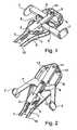
- FIG. 4shows a schematic representation of an embodiment of a sensor support unit 20, which can be glued to a patient for insertion of a sensor on the stomach, together with an insertion device coupled thereto, as described above, for example, with reference to the Figures 2 or 3 has been described.
- the insertion devicecarries a coupling mechanism 15, via which the insertion device is coupled to the sensor carrier unit 20 for insertion.
- the schematically illustrated coupling mechanism 15is designed as a scissor lever.
- two lever arms 16are arranged crosswise and pivotable about a connection point 17.
- coupling positionengage lower ends 16b of the lever arms 16 behind retaining elements 20a of the sensor support unit 20 and thus cause a mechanical connection between the insertion device and the sensor support unit 20th
- the two actuators 7 of the insertion devicearcuately along in FIG. 4 shown arrows B moves, as related to the Figures 2 and 3 was explained.
- the actuating elements 7strike the upper ends 16a of the lever arms 16 of the coupling mechanism 15.
- the upper ends 16a of the lever arms 16are pressed together, so that their lower ends 16b also move toward one another and thereby disengage from them detach the sensor carrier unit 20.
- the illustrated insertion devicedecouples at the end of an insertion process automatically from the sensor carrier unit 20 and can be easily removed from her.
- the upper ends 16a of the lever arms 16thus form actuating elements of the coupling mechanism.
- a useralso has the opportunity to release the insertion device from the sensor carrier unit by pressing directly with his fingers on the upper ends 16a of the lever arms 16 and so operates the scissor lever mechanism. In this way, a user has the opportunity to cancel an insertion process and to solve the insertion of this device from the sensor carrier unit.
- FIG. 5schematically shows another embodiment of a coupling mechanism 15 which connects the insertion device for insertion with a sensor support unit 20 and decoupled after completion of insertion.
- the in FIG. 5 schematically illustrated coupling mechanism 15has two arms 16 which are pivotally connected at a connection point 17 with each other.
- Each of the arms 16has an upper arm 16c and a lower arm 16d, which are hinged together like an elbow.
- the forearms 16dengage in the FIG. 5 shown coupling position in holding elements 20a of the sensor carrier unit 20 and thus cause a mechanical connection between the insertion device and the sensor carrier unit 20th
- the coupling mechanism 15is operated by the drive mechanism of the insertion device similarly to the above-described embodiment, so that the two articulated arms 16 of the coupling mechanism 15 are retracted at its connection point 17 in the direction of the arrow C. In doing so, the lower arms 16d move towards each other, so that the coupling mechanism 15 detaches from the sensor unit 20.
- the coupling mechanism 15comprises a sine crank mechanism with an arm 18 which is pivotally connected to the connecting point 17 of the two arms 16 as a connecting rod.
- the sine crank mechanismis driven by racks 8 of the drive mechanism, so the sensor carrier unit 20 is uncoupled from the insertion device at the end of an insertion process.
- FIG. 6schematically shows a variation of in FIG. 5 illustrated embodiment.
- the two arms 16are retracted by an arm 18 movable between two linear guides 19.
- the arm 18carries a link 21, which is traversed by a pin 22 at the end of an actuating movement.
- the pin 22is attached to one of the two actuators 7 and meets at the end of an actuating movement on an inclined surface of the link 21. This causes movement of the arm 18 in the direction of arrow C and thus uncoupling the insertion of the sensor carrier unit 20th ,
- FIG. 7shows a further embodiment, which is a modification of the above with reference to FIG. 6 illustrated coupling mechanism 15 represents.
- the linear guide 19is formed as a fixed to the housing 1 pin which engages in a slot of the arm 18.
- a single arm 16is mounted, which carries a bolt which engages for insertion into the holding elements 20a of the sensor carrier unit 20 and at the end of an insertion process by the arm 18 is pulled out of its engaged position, so that the sensor carrier unit 20th detached from the insertion device 1.
Landscapes
- Health & Medical Sciences (AREA)
- Life Sciences & Earth Sciences (AREA)
- Surgery (AREA)
- Public Health (AREA)
- Animal Behavior & Ethology (AREA)
- Engineering & Computer Science (AREA)
- Biomedical Technology (AREA)
- Heart & Thoracic Surgery (AREA)
- Veterinary Medicine (AREA)
- General Health & Medical Sciences (AREA)
- Pathology (AREA)
- Molecular Biology (AREA)
- Medical Informatics (AREA)
- Physics & Mathematics (AREA)
- Nuclear Medicine, Radiotherapy & Molecular Imaging (AREA)
- Biophysics (AREA)
- Optics & Photonics (AREA)
- Anesthesiology (AREA)
- Hematology (AREA)
- Vascular Medicine (AREA)
- Emergency Medicine (AREA)
- Gastroenterology & Hepatology (AREA)
- Oral & Maxillofacial Surgery (AREA)
- Infusion, Injection, And Reservoir Apparatuses (AREA)
- Automatic Assembly (AREA)
- Vending Machines For Individual Products (AREA)
- Auxiliary Devices For And Details Of Packaging Control (AREA)
Abstract
Description
Translated fromGermanDie Erfindung betrifft eine Insertionsvorrichtung mit den im Oberbegriff des Anspruchs 1 angegebenen Merkmalen. Derartige Insertionsvorrichtungen sind aus der
Um Sensoren zur Messung von Analytkonzentrationen in vivo, beispielsweise der Glukosekonzentrationen, in Körpergewebe eines Patienten zu insertieren, beispielsweise im Unterhautfettgewebe, werden Insertionsvorrichtungen verwendet, die mit einem Antriebsmechanismus eine Stichbewegung einer Insertionsnadel bewirken. Hierfür gebräuchliche Insertionsnadeln sind als Hohlnadeln oder V-förmige Rinnen ausgebildet, in denen ein Sensor liegt. Der Sensor kann beispielsweise als ein Elektrodensystem für elektrochemische Messungen ausgebildet sein oder einen mikrofluidischen Katheter zum Ein- und Ausleiten einer Perfusionsflüssigkeit umfassen. Nach einem Einstich wird die Insertionsnadel aus dem Körpergewebe herausgezogen, wobei der Sensor in der erzeugten Stichwunde verbleibt.In order to insert sensors for measuring analyte concentrations in vivo, for example glucose concentrations, in body tissue of a patient, for example in subcutaneous fatty tissue, insertion devices are used which cause a puncture movement of an insertion needle with a drive mechanism. For this customary insertion needles are designed as hollow needles or V-shaped grooves in which a sensor is located. The sensor can be designed, for example, as an electrode system for electrochemical measurements or comprise a microfluidic catheter for introducing and removing a perfusion fluid. After a puncture, the insertion needle is pulled out of the body tissue, with the sensor remaining in the created puncture wound.
Eine weitere Anwendung von Insertionsvorrichtungen ist beispielsweise die Applikation von Kathetern, beispielsweise zur Infusion von Insulin oder anderen Wirkstoffen.Another application of insertion devices is, for example, the application of catheters, for example for the infusion of insulin or other active ingredients.
Bei einfachen Insertionsvorrichtungen setzt ein Antriebsmechanismus eine Antriebsbewegung eines Betätigungselements in eine lineare Stichbewegung der Insertionsnadel um. Die für einen Stich erforderliche Kraft muss ein Benutzer durch eine entsprechende Antriebsbewegung des Betätigungselements also während der Insertion selbst aufbringen. Dies macht es vielen Benutzern mühsam, derartige Insertionsvorrichtungen bei sich selbst anzuwenden, beispielsweise um sich einen Sensor im Unterhautfettgewebe des Bauchs zu insertieren. Insbesondere Menschen, deren Beweglichkeit durch Alter oder Krankheit eingeschränkt ist, fällt es schwer, eine Insertionsvorrichtung im richtigen Winkel an ihren Körper zu halten und dabei die für einen Stich erforderliche Kraft aufzubringen. Das Aufbringen von Kraft erschwert es nämlich, die Insertionsvorrichtung beim Betätigen ruhig zu halten und nicht zu verkippen. Eine zittrige Hand beim Stechen oder ein Kippen der Insertionsvorrichtung führen zu schmerzhaften Querbewegungen der Insertionsnadel und im Extremfall zu einem gescheiterten Insertionsversuch. Insbesondere können Querbewegungen beim Einstich dazu führen, dass der insertierte Sensor durch umgebendes Körpergewebe später mechanischen Spannungen ausgesetzt ist, die den Sensor belasten und sogar verbiegen können. Zudem wird das Körpergewebe dabei ständig gereizt, so dass verstärkt Entzündungen und Abstoßungsreaktionen auftreten, die Messungen des Sensors beeinträchtigen.In simple insertion devices, a drive mechanism converts a drive movement of an actuating element into a linear stitch movement of the insertion needle. The force required for a stitch must be applied by a user by a corresponding drive movement of the actuating element during the insertion itself. This makes it difficult for many users to apply such insertion devices to themselves, for example, to insert a sensor in the subcutaneous fatty tissue of the abdomen. In particular, people whose mobility is limited by age or disease, it is difficult to keep an insertion device at the correct angle to her body and thereby apply the necessary force for a stitch. The application of power namely makes it difficult to keep the insertion device when operating quiet and not tilt. A shaky hand when stinging or tilting the insertion device lead to painful transverse movements of the insertion needle and in extreme cases to a failed insertion attempt. In particular, transverse movements during puncture may result in the inserted sensor being later exposed to environmental stresses by surrounding body tissue, which may stress and even bend the sensor. In addition, the body tissue is constantly irritated, so that increased inflammation and rejection reactions occur that affect the measurements of the sensor.
Diese Nachteile lassen sich durch aufwendigere Insertionsvorrichtungen mit federgetriebenen Antriebsmechanismen weitgehend beheben. Bei derartigen Insertionsvorrichtungen wird die für eine Stichbewegung erforderliche Energie von einer Antriebsfeder oder einem anderen Energiespeicher geliefert. Zur Insertion muss ein Benutzer eine derartige Insertionsvorrichtung lediglich an eine geeignete Körperstelle ansetzen und einen Stich auslösen, beispielsweise durch Druck auf ein Auslöseelement. Der Kraftaufwand hierfür ist minimal, so dass es selbst Personen mit eingeschränkter Beweglichkeit leicht fällt, die Insertionsvorrichtung beim Insertionsvorgang ruhig zu halten.These disadvantages can be largely eliminated by more expensive insertion devices with spring-driven drive mechanisms. In such insertion devices, the energy required for a stitch movement is supplied by a drive spring or another energy store. For insertion, a user must attach such an insertion device only to a suitable body site and trigger a stitch, for example by pressure on a trigger element. The effort required for this is minimal, so that it is easy even for people with limited mobility to keep the insertion device during the insertion process quiet.
Aufgabe der Erfindung ist es, einen Weg aufzuzeigen, wie mit geringerem Aufwand eine einfach zu handhabende Insertionsvorrichtung zur Verfügung gestellt werden kann.The object of the invention is to show a way, as with less effort an easy-to-use insertion device can be provided.
Diese Aufgabe wird durch eine Insertionsvorrichtung mit den im Anspruch 1 angegebenen Merkmalen gelöst. Vorteilhafte Weiterbildungen der Erfindung sind Gegenstand der Unteransprüche.This object is achieved by an insertion device having the features specified in claim 1. Advantageous developments of the invention are the subject of the dependent claims.
Bei einer erfindungsgemäßen Insertionsvorrichtung setzt der Antriebsmechanismus eine quer oder entgegengesetzt zur Stichrichtung verlaufende Antriebsbewegung von einem oder mehreren Betätigungselementen in eine Stichbewegung des Insertionsnadelhalters um. Obwohl ein Benutzer die Kraft für eine Stichbewegung durch manuelles Einwirken auf das Betätigungselement selbst aufbringen muss, lässt sich eine erfindungsgemäße Insertionsvorrichtung sehr leicht handhaben, indem die Antriebsbewegung des Betätigungselements quer zur Stichrichtung verläuft. Eine Bewegung quer zur Stichrichtung lässt sich nämlich aus ergonomischen Gründen wesentlich leichter durchführen als eine Bewegung in Stichrichtung. Ähnliches gilt für eine Bewegung entgegengesetzt zur Stichrichtung. Selbst Personen mit eingeschränkter Beweglichkeit können sich deshalb mit einer erfindungsgemäßen Insertionsvorrichtung mit ruhiger Hand einen Sensor oder einen Infusionskatheter einsetzen, beispielsweise in den Oberarm oder das Unterhautfettgewebe des Bauchs.In an insertion device according to the invention, the drive mechanism converts a transverse or opposite to the stitch direction extending drive movement of one or more actuators in a stitch movement of the insertion needle holder. Although a user must apply the force for a stitch movement by manually acting on the actuator itself, an insertion device according to the invention can be handled very easily by the drive movement of the actuating element extends transversely to the stitching direction. A movement transverse to the stitch direction can be carried out for ergonomic reasons, namely much easier than a movement in the needle direction. The same applies to a movement opposite to the stitching direction. Even persons with limited mobility can therefore use a sensor or an infusion catheter with an insertion device according to the invention with a steady hand, for example in the upper arm or the subcutaneous fatty tissue of the abdomen.
Eine erfindungsgemäße Insertionsvorrichtung hat zudem einen wichtigen psychologischen Vorteil. Da die für eine Stichbewegung erforderliche Kraft quer oder entgegengesetzt zur Stichrichtung aufgebracht wird, hat ein Benutzer nicht das Gefühl, diese Kraft gegen sich selbst zu richten. Selbst wenn die Stichbewegung während der Antriebsbewegung erfolgt, muss zum Betätigen der Insertionsvorrichtung allenfalls eine kleine psychologische Hemmschwelle überwunden werden. Die bei jedem Menschen mehr oder weniger stark ausgeprägte Hemmschwelle dagegen, wissentlich einen spitzen Gegenstand mit einer erhöhten Kraft in Richtung des eigenen Körpers zu treiben, entfällt bei einer erfindungsgemäßen Insertionsvorrichtung.An insertion device according to the invention also has an important psychological advantage. Since the force required for a stitch movement is applied transversely or opposite to the stitch direction, a user does not feel that force is directed against himself. Even if the stitch movement occurs during the drive movement, at most a small psychological inhibition threshold must be overcome to operate the insertion device. By contrast, the more or less pronounced inhibition threshold in every human being, knowingly driving a pointed object with an increased force in the direction of one's own body, does not apply to an insertion device according to the invention.
Ein weiterer Vorteil der erfindungsgemäßen Lösung, die Antriebsbewegung des Betätigungselements quer zur Stichrichtung auszuführen, liegt darin, dass die Insertionsvorrichtung selbst und nicht der eigene Körper als Widerlager der Betätigungskraft wirkt. Dies erleichtert es einem Benutzer, das Körperteil, in das mit der Insertionsnadel eingestochen werden soll, zu entspannen, die Insertionsvorrichtung ruhiger zu halten und trägt auf diese Weise zu einer schmerzärmeren Insertion mit weniger mechanischen Spannungen bei.Another advantage of the inventive solution to perform the drive movement of the actuator transverse to the needle direction is that the insertion device itself and not the own body acts as an abutment of the actuating force. This makes it easier for a user to relax the body part into which the insertion needle is to be inserted, making the insertion device calmer and thus contributes to a less painful insertion with less mechanical stress.
Eine erfindungsgemäße Insertionsvorrichtung kann so konstruiert sein, dass die quer zur Stichrichtung verlaufende Antriebsbewegung des Betätigungselements senkrecht zur Stichrichtung erfolgt. Zwingend erforderlich ist dies jedoch nicht. Auch eine Antriebsbewegung, die in einer anderen nicht zur Stichrichtung parallelen Richtung erfolgt, ist quer zur Stichrichtung und ermöglicht es, die vorstehend beschriebenen Vorteile zu nutzen. Insbesondere ist es nicht unbedingt erforderlich, dass die Antriebsbewegung des Betätigungselements eine lineare Bewegung ist. Beispielsweise kann die Antriebsbewegung des Betätigungselements auch eine Schwenkbewegung sein. Je kleiner nämlich der Winkel ist, der bei einer Schwenkbewegung überstrichen wird und je größer der Radius der Schwenkbewegung ist, desto geringer wird ergonomisch der Unterschied zu einer linearen Bewegung.An insertion device according to the invention may be constructed such that the drive movement of the actuating element, which extends transversely to the stiching direction, takes place perpendicular to the stiching direction. However, this is not absolutely necessary. Also, a drive movement that occurs in another direction that is not parallel to the stitching direction is transverse to the stitching direction and makes it possible to utilize the advantages described above. In particular, it is not absolutely necessary that the drive movement of the actuating element is a linear movement. For example, the drive movement of the actuating element can also be a pivoting movement. Namely, the smaller the angle that is swept over in a pivoting movement and the larger the radius of the pivoting movement, the lower the ergonomic difference to a linear movement.
Für eine erfindungsgemäße Insertionsvorrichtung wird vorteilhaft weder eine Feder noch ein anderer Energiespeicher benötigt. Der Antriebsmechanismus einer erfindungsgemäßen Insertionsvorrichtung kann deshalb energiespeicherfrei und folglich kostengünstig sein. Eine erfindungsgemäße Insertionsvorrichtung kann deshalb auch als ein Wegwerfartikel ausgebildet sein, der nach einmaligem Gebrauch entsorgt wird. Eine Sicherung gegen eine unerwünschte Mehrfachverwendung kann erreicht werden, indem sich der Antriebsmechanismus nach Gebrauch verriegelt, beispielsweise indem das Betätigungselement am Ende der Antriebsbewegung einrastet.For an insertion device according to the invention advantageously neither a spring nor another energy storage is needed. The drive mechanism of an insertion device according to the invention can therefore be energy storage-free and therefore inexpensive. An insertion device according to the invention can therefore also be designed as a disposable article, which is disposed of after a single use. A safeguard against unwanted multiple use can be achieved by locking the drive mechanism after use, for example by the actuator engages at the end of the drive movement.
Sofern eine besonders schnelle Stichbewegung der Insertionsnadel gewünscht ist, kann dies erreicht werden, indem die Hand des Benutzers als Energiespeicher genutzt wird. Eine Möglichkeit hierzu ist es, eine Bewegung des Betätigungselements durch eine Sperre zu blockieren, die erst bei Erreichen einer vorgegeben Kraft überwunden wird, beispielsweise indem ein Sperrelement bricht oder durch elastische Verformung überwunden wird. Das plötzliche Überwinden einer solchen Sperre führt dazu, dass der Benutzer das Betätigungselement dann wesentlich schneller bewegt als es ohne eine solche Sperre möglich wäre.If a particularly fast stitch movement of the insertion needle is desired, this can be achieved by using the user's hand as an energy store. One possibility for this is to block a movement of the actuating element by a lock, which is overcome only when a predetermined force is reached, for example by a blocking element breaks or is overcome by elastic deformation. The sudden overcoming of such a lock causes the user to move the actuator much faster than would be possible without such a lock.
Eine erfindungsgemäße Insertionsvorrichtung kann auch wieder verwendbar gestaltet werden, indem in den Insertionsnadelhalter immer wieder neue Insertionsnadeln eingesetzt werden können. Während bei einer disposiblen Vorrichtung zum einmaligen Gebrauch in den Insertionsnadelhalter in der Regel bereits vom Hersteller eine Insertionsnadel eingesetzt wird, können Insertionsvorrichtungen zum mehrmaligen Gebrauch auch ohne in den Insertionsnadelhalter eingesetzte Insertionsnadeln vertrieben werden, da ein Benutzer separat vertriebene Insertionsnadeln selbst in den Insertionsnadelhalter einsetzen kann. Bei einer wieder verwendbaren Insertionsvorrichtung kann es vorteilhaft sein, eine Rückstellfeder vorzusehen, die das oder die Betätigungselemente nach Betätigung zum erneuten Gebrauch in eine Ausgangsposition zurückbewegt. Die mechanischen Anforderungen an eine derartige Rückstellfeder sind außerordentlich gering, so dass eine solche Rückstellfeder kostengünstig, beispielsweise aus Kunststoff, hergestellt werden kann.An insertion device according to the invention can also be designed to be reusable by repeatedly inserting new insertion needles into the insertion needle holder. While in a disposable device for single use in the insertion needle holder usually an insertion needle is already used by the manufacturer, insertion devices for repeated use can be sold even without inserted into the insertion needle insertion insertion needles, as a user can use separately sold insertion needles even in the insertion needle holder. In a reusable insertion device, it may be advantageous to provide a return spring which moves the actuation element (s) back into an initial position for reuse after actuation. The mechanical requirements for such a return spring are extremely low, so that such a return spring cost, for example, made of plastic, can be produced.
Um die quer zur Stichrichtung verlaufende Antriebsbewegung des Betätigungselements in eine lineare Stichbewegung des Insertionsnadelhalters umzusetzen, wird ein Antriebsmechanismus mit einem Pleuel verwendet. Indem die Antriebsbewegung zunächst eine Dreh- oder Schwenkbewegung bewirkt, kann auf diese Weise mit geringerem Aufwand die für eine Stichbewegung erforderliche lineare Bewegung erzeugt werden. Der Antriebsmechanismus weist einen mit dem Betätigungselemente gekoppelten Rotor und einen mit dem Rotor gekoppelten Pleuel auf, der eine Drehbewegung des Rotors in eine lineare Bewegung des Insertionsnadelhalters umsetzt. Eine Kopplung des Betätigungselements mit dem Rotor kann beispielsweise über eine Zahnstange erfolgen.In order to implement the transverse to the stitching direction drive movement of the actuating element in a linear stitch movement of the insertion needle holder, a drive mechanism is used with a connecting rod. By the drive movement initially causes a rotary or pivotal movement, the required for a stitch movement linear movement can be generated in this way with less effort. The drive mechanism has a rotor coupled to the actuator and a connecting rod coupled to the rotor which converts a rotational movement of the rotor into a linear movement of the insertion needle holder. A coupling of the actuating element with the rotor can for example take place via a toothed rack.
Prinzipiell genügt bei einer erfindungsgemäßen Insertionsvorrichtung ein einziges Betätigungselement, das quer zur Stichrichtung beweglich ist. Besonders vorteilhaft ist es jedoch, die Insertionsvorrichtung mit zwei gegenüberliegend angeordneten Betätigungselementen auszustatten. Von den Betätigungselementen auf das Gerät bzw. den Antriebsmechanismus ausgeübte Quer- und Reaktionskräfte lassen sich auf diese Weise kompensieren. Zudem kann ein Gerät mit zwei gegenüberliegend angeordneten Betätigungselementen von Rechtshändern ebenso gut wie von Linkshändem verwendet werden. Bevorzugt ist dabei, dass die beiden Betätigungselemente derart mit dem Antriebsmechanismus gekoppelt sind, dass sie sich bei einer Stichbewegung in entgegengesetzter Richtung bewegen. Beispielsweise können sich die beiden Betätigungselemente bei einer Stichbewegung aufeinander zu bewegen. Dies ermöglicht es, die für eine Stichbewegung erforderliche Kraft manuell beispielsweise dadurch aufzubringen, indem das Gerät mit einer Hand umfasst und die Hand zusammengedrückt wird. Eine solche Bewegung entspricht dem Ballen einer Faust, ist also eine sehr einfache Bewegung, die keine besondere Präzision oder Koordination erfordert. Derartige Bewegungen können zudem ausgeführt werden, ohne dass eine Reaktionskraft auf den Körper des Patienten übertragen wird. Die Gefahr eines Verkippens des Geräts während des Insertionsvorgangs lässt sich deshalb wesentlich reduzieren.In principle, in the case of an insertion device according to the invention, a single actuating element which is movable transversely to the sting direction is sufficient. However, it is particularly advantageous to equip the insertion device with two oppositely arranged actuating elements. Transverse and reaction forces exerted on the device or drive mechanism by the actuators can be compensated in this way. In addition, a device with two oppositely located actuators by right-handers can be used as well as left-handed. It is preferred that the two actuators are coupled to the drive mechanism so that they move in a stitch movement in the opposite direction. For example, the two actuators can move towards each other during a stitch movement. This makes it possible to manually apply the force required for a stitch movement, for example, by the device with one hand and the hand is compressed. Such a movement corresponds to the bale of a fist, so is a very simple movement that requires no special precision or coordination. Such movements may also be performed without transmitting a reaction force to the body of the patient. The risk of tilting the device during the insertion process can therefore be significantly reduced.
Insertierbare Sensoren werden üblicherweise zusammen mit einer Sensorträgereinheit verwendet, die einem Patienten auf den Bauch geklebt werden kann. Zur Insertion eines Sensors kann eine Insertionsvorrichtung mit einer solchen Sensorträgereinheit gekoppelt werden. Nach beendeter Insertion wird die Insertionsvorrichtung üblicherweise von der Sensorträgereinheit gelöst, die am Körper des Patienten verbleibt. Klebende Sensorträgereinheiten mit einer dazu passenden Insertionsvorrichtung sind beispielsweise aus der
Eine vorteilhafte Weiterbildung der vorliegenden Erfindung sieht deshalb vor, dass die Insertionsvorrichtung einen Kopplungsmechanismus trägt, der bei einer Insertion eine Sensorträgereinheit an der Insertionsvorrichtung hält und am Ende eines Insertionsvorgangs von dem Antriebsmechanismus betätigt wird, so dass sich die Sensorträgereinheit von der Insertionsvorrichtung löst. Dabei kann es vorteilhaft sein, zusätzlich zu dieser automatischen Abkopplung nach abgeschlossener Insertion eine vorzeitige Abkopplung zu ermöglichen, beispielsweise um eine schmerzhafte Insertion abzubrechen. Hierfür kann der Kopplungsmechanismus mit einem Betätigungselement versehen werden, das ein Benutzer ohne Einwirkung des Antriebsmechanismus betätigen kann.An advantageous development of the present invention therefore provides that the insertion device carries a coupling mechanism which holds a sensor carrier unit to the insertion device at an insertion and is actuated at the end of an insertion process by the drive mechanism, so that the sensor carrier unit detaches from the insertion device. It may be advantageous, in addition to this automatic decoupling after completed insertion to allow premature decoupling, for example, to cancel a painful insertion. For this purpose, the coupling mechanism can be provided with an actuating element, which can operate a user without the action of the drive mechanism.
Bevorzugt hat der Kopplungsmechanismus zwei gelenkig miteinander verbundene Arme, welche die Sensorträgereinheit halten und von dem Antriebsmechanismus bewegt werden, um die Insertionsvorrichtung von der Sensorträgereinheit abzukoppeln.Preferably, the coupling mechanism has two hingedly connected arms holding the sensor carrier unit and the drive mechanism are moved to decouple the insertion device from the sensor carrier unit.
Weitere Einzelheiten und Vorteile der Erfindung werden an Ausführungsbeispielen unter Bezugnahme auf die beigefügten Zeichnungen erläutert. Gleiche und einander entsprechende Bauteile sind dabei mit übereinstimmenden Bezugszahlen bezeichnet. Es zeigen:
- Figur 1:
- ein Ausführungsbeispiel einer erfindungsgemäßen Insertionsvorrichtung bei geöffnetem Gehäuse;
- Figur 2:
- ein weiteres Ausführungsbeispiel einer erfindungsgemäßen Insertions- vorrichtung bei geöffnetem Gehäuse;
- Figur 3:
- ein weiteres Ausführungsbeispiel einer erfindungsgemäßen Insertions- vorrichtung bei geöffnetem Gehäuse;
- Figur 4:
- eine schematische Darstellung der Kopplung einer Insertionsvorrich- tung an eine Sensorträgereinheit;
Figur 5- eine schematische Darstellung eines weiteren Ausführungsbeispiels der Kopplung einer Insertionsvorrichtung an eine Sensorträgereinheit;
Figur 6- eine schematische Darstellung eines weiteren Ausführungsbeispiels der Kopplung einer Insertionsvorrichtung an eine Sensorträgereinheit; und
Figur 7- eine schematische Darstellung eines weiteren Ausführungsbeispiels der Kopplung einer Insertionsvorrichtung an eine Sensorträgereinheit.
- FIG. 1:
- an embodiment of an insertion device according to the invention with the housing open;
- FIG. 2:
- a further embodiment of an insertion device according to the invention with the housing open;
- FIG. 3:
- a further embodiment of an insertion device according to the invention with the housing open;
- FIG. 4:
- a schematic representation of the coupling of an insertion device to a sensor carrier unit;
- FIG. 5
- a schematic representation of another embodiment of the coupling of an insertion device to a sensor carrier unit;
- FIG. 6
- a schematic representation of another embodiment of the coupling of an insertion device to a sensor carrier unit; and
- FIG. 7
- a schematic representation of another embodiment of the coupling of an insertion device to a sensor carrier unit.
Die in
In ihrem in
Vorteilhaft kompensieren sich die von den Betätigungselementen 7 auf den Rotor 8 ausgeübte Querkräfte, so dass reibungserhöhende Ausweichbewegungen des Rotors vermieden werden.Advantageously, the lateral forces exerted by the
Das Gehäuse 1 hat eine schräg zur Stichrichtung verlaufende Unterseite 10, mit der die Insertionsvorrichtung bei Gebrauch an den Körper eines Patienten angesetzt wird. Bevorzugt verläuft die Unterseite 10 unter einem Winkel von 30° bis 60° zur Stichrichtung, so dass eine Insertionsnadel 3 schräg in das Unterhautfettgewebe eines Benutzers eingestochen werden kann. Durch das Gehäuse 1 ist die Insertionsnadel 3 für einen Benutzer nicht sichtbar, was aus psychologischen Gründen vorteilhaft ist.The housing 1 has an
Die dargestellte Insertionsvorrichtung dient zum Insertieren eines Sensors für in vivo Messungen, beispielsweise zur Messung der Glukosekonzentration. Der Antriebsmechanismus setzt deshalb die quer zur Stichrichtung verlaufende Antriebsbewegung der Betätigungselemente 7 sowohl in eine Stichbewegung als auch in eine unmittelbar anschließende Rückzugsbewegung des Insertionsnadelhalters 2 um. Dies wird dadurch erreicht, dass die Länge der Zahnstangen 8 der Betätigungselemente 7 genau passend für eine volle 360°-Drehung des Rotors 6 sind. Im vorderen Wendepunkt der Bewegung des Insertionsnadelhalters 2 wird ein an die Insertionsnadel 3 angekoppelter Sensor von der Insertionsnadel 3 getrennt und bleibt somit bei der Rückzugsbewegung in der erzeugten Stichwunde im Körper des Patienten. Die Insertion eines Sensors erfolgt auf diese Weise in dem durchgängigen Bewegungsablauf. Der Patient nimmt lediglich einen Ausgangszustand beim Ansetzten der Insertionsvorrichtung und einen Endzustand nach abgeschlossener Insertion wahr.The insertion device shown serves for inserting a sensor for in vivo measurements, for example for measuring the glucose concentration. Therefore, the drive mechanism sets the transverse to the sting direction drive movement of the
Am Ende ihres Betätigungsweges rasten die Betätigungselemente 7 ein, beispielsweise indem sie im oder mit dem Gehäuse 1 verrasten. Auf diese Weise wird der Antriebsmechanismus verriegelt, so dass die Insertionsvorrichtung nur für einen einmaligen Gebrauch verwendet werden kann. Zudem wird durch das Verriegeln des Antriebsmechanismus erreicht, dass die Insertionsnadel 3 nach Gebrauch im Gehäuse 1 bleibt und der Benutzer somit vor einer Verletzung durch eine gebrauchte Insertionsnadel 3 geschützt ist.At the end of their actuation path, the
Bei der dargestellten Insertionsvorrichtung wird die für eine Stichbewegung erforderliche Kraft während des Stichs vom Benutzer durch die manuelle Betätigung der Betätigungselemente 7 erzeugt. Vorteilhaft wird deshalb weder eine Antriebsfeder noch ein sonstiger Energiespeicher benötigt. Die dargestellte Insertionsvorrichtung ist somit energiespeicherfrei. Energiespeicherfreie Insertionsvorrichtungen werden auch als manuelle Insertionsvorrichtungen bezeichnet.In the illustrated insertion device, the force required for a stitch movement is generated during the stitch by the user by the manual actuation of the
Zum Betätigen des Antriebsmechanismus werden die beiden Betätigungselemente 7 ebenso wie bei dem vorstehend beschriebenen Ausführungsbeispiel zusammengedrückt. Die Betätigungselemente 7 sind über einen Faden 12 mit einem als Kurbelwelle ausgebildeten Rotor 6 gekoppelt, so dass die Schwenkbewegung der Betätigungselemente 7 eine Drehbewegung des Rotors 6 bewirkt. Der Rotor 6 ist ebenso wie bei dem vorstehend beschriebenen Ausführungsbeispiel über eine Kurbel 5 mit einem Pleuel 4 gekoppelt, so dass die Drehbewegung des Rotors 6 in eine lineare Stechbewegung des Insertionsnadelhalters 2 umgesetzt wird.To operate the drive mechanism, the two
Die Gehäuse 1 der Insertionsvorrichtungen können beispielsweise durch Zusammenfügen von zwei Halbschalen gebildet werden. Eine dieser Halbschalen kann hierfür mit Zapfen oder anderen Verbindungselementen versehen werden, die in komplementäre Verbindungselemente 13 der anderen Halbschale eingreifen, beispielsweise in Hohlzapfen oder Buchsen. Möglich ist es auch, das Gehäuse einteilig als zwei über ein Filmscharnier verbundene Hälften auszubilden, die zum Schließen des Gehäuses zusammengeklappt und verrastet oder stoffschlüssig, beispielsweise durch Kleben oder Schweißen verbunden werden. Ein Filmscharnier ist eine Verbindung zwischen zwei Bauteilen, die wegen ihrer reduzierten Materialstärke biegsam ist und so eine Schwenkbewegung der beiden Bauteile zueinander ermöglicht.The housing 1 of the insertion devices can be formed for example by joining two half-shells. One of these half-shells can be provided for this purpose with pins or other connecting elements which engage in complementary connecting
Zur Reduktion von Bauteilen lässt sich ein solches Filmscharnier auch an anderen Stellen bei den beschrieben Ausführungsbeispielen einsetzten. Beispielsweise kann der Insertionsnadelhalter 2 über ein Filmscharnier mit dem Pleuel 4 ausgebildet sein. Möglich ist es auch, das Schwenklager 11 des in
Bei dem in
Bei einer Insertion werden die beiden Betätigungselemente 7 der Insertionsvorrichtung bogenförmig entlang der in
Ein Benutzer hat zudem die Möglichkeit, die Insertionsvorrichtung von der Sensorträgereinheit zu lösen, indem er direkt mit seinen Fingern auf die oberen Enden 16a der Hebelarme 16 drückt und so den Scherenhebelmechanismus betätigt. Auf diese Weise hat ein Benutzer die Möglichkeit, einen Insertionsvorgang abzubrechen und die Insertionsvorrichtung hierfür von Sensorträgereinheit zu lösen.A user also has the opportunity to release the insertion device from the sensor carrier unit by pressing directly with his fingers on the upper ends 16a of the
Der in
An Ende eines Insertionsvorgangs wird der Koppelungsmechanismus 15 ähnlich wie bei dem vorstehend beschriebenen Ausführungsbeispiel von dem Antriebsmechanismus der Insertionsvorrichtung betätigt, so dass die beiden Gelenkarme 16 des Kopplungsmechanismus 15 an ihrem Verbindungspunkt 17 in Richtung des Pfeils C zurückgezogen werden. Dabei bewegen sich die Unterarme 16d aufeinander zu, so dass sich der Kopplungsmechanismus 15 von der Sensoreinheit 20 löst.At the end of an insertion operation, the
Bei dem in
- 11
- Gehäusecasing
- 22
- Insertionsnadelhalterinsertion needle
- 33
- Insertionsnadelinsertion needle
- 44
- Pleuelpleuel
- 55
- Kurbelcrank
- 66
- Rotorrotor
- 77
- Betätigungselementactuator
- 88th
- Zahnstangerack
- 99
- Linearführunglinear guide
- 1010
- GehäuseunterseiteHousing bottom
- 1111
- Schwenklagerpivot bearing
- 1212
- Fadenthread
- 1313
- Verbindungselementconnecting element
- 1515
- Kopplungsmechanismuscoupling mechanism
- 1616
- Armpoor
- 16a16a
- oberes Ende des Armsupper end of the arm
- 16b16b
- unteres Ende des Armslower end of the arm
- 16c16c
- Oberarmupper arm
- 16d16d
- Unterarmforearm
- 1717
- Verbindungspunktjunction
- 1818
- Armpoor
- 1919
- Linearführunglinear guide
- 2020
- SensorträgereinheitSensor carrier unit
- 20a20a
- Halteelementretaining element
- 2121
- Kulissescenery
- 2222
- Zapfenspigot
Claims (13)
- An insertion device comprising
an insertion needle holder (2),
a drive mechanism (4, 5, 6, 12) for linearly moving the insertion needle holder (2) in a puncturing direction, and
at least one actuating element (7) for actuating a drive mechanism (4, 5, 6, 12), wherein
the drive mechanism (4, 5, 6, 12) converts a driving motion of the actuating element (7), the driving motion proceeding transversely or opposite to the puncturing direction, into a puncturing motion of the insertion needle holder (2),
characterized in that the drive mechanism (4, 5, 6, 12) includes a rotor (6) and a connecting rod (4) coupled to the rotor (6), the connecting rod converting rotary motion of the rotor (6) into linear motion of the insertion needle holder (2). - The insertion device according to claim 1,characterized in that the puncturing motion occurs during the driving motion.
- The insertion device according to one of the preceding claims,characterized in that the drive mechanism (4, 5, 6, 12) does not include an energy accumulator.
- The insertion device according to any one of the preceding claims,characterized in that the drive mechanism (4, 5, 6, 12) converts the driving motion of the actuating element (7) into rotary motion of the rotor (6).
- The insertion device according to any one of the preceding claims,characterized in that the drive motion of the actuating element (7) is a swivelling motion.
- The insertion device according to any one of the preceding claims,
characterized in that the actuating element (7) includes a gear rod (8). - The insertion device according to any one of the preceding claims,
characterized in that the drive mechanism (4, 5, 6, 12) is disposed in a housing (1), out of which the actuating element (7) protrudes. - The insertion device according to any one of the preceding claims,
characterized in that two actuating elements (7) are diametrically opposed. - The insertion device according to any one of the preceding claims,
characterized in that the two actuating elements (7) move in the opposite direction when a puncturing motion occurs. - The insertion device according to any one of the preceding claims,
characterized in that the two actuating elements (7) move toward one another when a puncturing motion occurs. - The insertion device according to any one of the preceding claims,
characterized in that the drive mechanism (4, 5, 6, 12) converts a driving motion of the actuating element (7), the driving motion proceeding transversely to the puncturing direction, into a puncturing motion and, immediately thereafter, into a retraction motion of the insertion needle holder (2). - The insertion device according to any one of the preceding claims,
characterized by a linear guide (9) for the insertion needle holder (2). - An insertion system comprising an insertion device according to any one of the preceding claims, and a sensor carrier unit (20),characterized in that the insertion device comprises a coupling mechanism that, for insertion, holds the sensor carrier unit (20) against the insertion device and is actuated by the drive mechanism (4, 5, 6, 12) at the end of an insertion procedure to detach the sensor carrier unit (20) from the insertion device.
Priority Applications (8)
| Application Number | Priority Date | Filing Date | Title |
|---|---|---|---|
| ES08017529TES2371686T3 (en) | 2008-10-07 | 2008-10-07 | INSERTION DEVICE |
| EP08017529AEP2174680B1 (en) | 2008-10-07 | 2008-10-07 | Insertion device |
| AT08017529TATE527007T1 (en) | 2008-10-07 | 2008-10-07 | INSERTION DEVICE |
| CN200980139700.6ACN102170928B (en) | 2008-10-07 | 2009-09-22 | Insertion device |
| PCT/EP2009/006823WO2010040448A1 (en) | 2008-10-07 | 2009-09-22 | Insertion device |
| HK12101914.7AHK1161156B (en) | 2008-10-07 | 2009-09-22 | Insertion device |
| US13/079,957US9629958B2 (en) | 2008-10-07 | 2011-04-05 | Insertion device |
| US15/434,412US10537357B2 (en) | 2008-10-07 | 2017-02-16 | Insertion device |
Applications Claiming Priority (1)
| Application Number | Priority Date | Filing Date | Title |
|---|---|---|---|
| EP08017529AEP2174680B1 (en) | 2008-10-07 | 2008-10-07 | Insertion device |
Publications (2)
| Publication Number | Publication Date |
|---|---|
| EP2174680A1 EP2174680A1 (en) | 2010-04-14 |
| EP2174680B1true EP2174680B1 (en) | 2011-10-05 |
Family
ID=40405074
Family Applications (1)
| Application Number | Title | Priority Date | Filing Date |
|---|---|---|---|
| EP08017529AActiveEP2174680B1 (en) | 2008-10-07 | 2008-10-07 | Insertion device |
Country Status (6)
| Country | Link |
|---|---|
| US (2) | US9629958B2 (en) |
| EP (1) | EP2174680B1 (en) |
| CN (1) | CN102170928B (en) |
| AT (1) | ATE527007T1 (en) |
| ES (1) | ES2371686T3 (en) |
| WO (1) | WO2010040448A1 (en) |
Families Citing this family (11)
| Publication number | Priority date | Publication date | Assignee | Title |
|---|---|---|---|---|
| EP2404632B1 (en) | 2010-07-10 | 2012-11-21 | Roche Diagnostics GmbH | Insertion system for needles |
| CN105611957B (en)* | 2013-09-05 | 2019-09-27 | 赛诺菲-安万特德国有限公司 | Drive mechanism for contact assemblies |
| RU2705613C2 (en) | 2014-07-22 | 2019-11-11 | Ф. Хоффманн-Ля Рош Аг | Sensor insertion device equipped with safety device |
| RU2017101849A (en) | 2014-07-22 | 2018-08-22 | Ф.Хоффманн-Ля Рош Аг | DEVICE FOR INTRODUCING A SENSOR WITH PROTECTION AGAINST RE-USE |
| CH709930A2 (en)* | 2014-07-29 | 2016-01-29 | Tecpharma Licensing Ag | Insertion device for an infusion. |
| EP3170452B1 (en) | 2015-11-19 | 2021-01-27 | Roche Diabetes Care GmbH | Sensor assembly for detecting at least one analyte in a body fluid |
| EP3170453B1 (en) | 2015-11-19 | 2021-03-17 | Roche Diabetes Care GmbH | Sensor assembly for detecting at least one analyte in a body fluid and method of assembling a sensor assembly |
| JP7126544B2 (en) | 2017-07-07 | 2022-08-26 | ニューロダーム リミテッド | Vial adapter, method and filling system for filling a reservoir of a drug delivery device with a flowable drug using the vial adapter |
| US20230123806A1 (en) | 2017-07-07 | 2023-04-20 | Neuroderm, Ltd. | Device for subcutaneous delivery of fluid medicament |
| CN112043414B (en)* | 2020-08-12 | 2021-09-21 | 王元祥 | Fixing device for lumbar puncture operation of children |
| TWI890917B (en)* | 2021-01-21 | 2025-07-21 | 瑞士商安晟信醫療科技控股公司 | Biosensor inserters and methods with reduced medical waste |
Family Cites Families (22)
| Publication number | Priority date | Publication date | Assignee | Title |
|---|---|---|---|---|
| US4448193A (en)* | 1982-02-26 | 1984-05-15 | Ethicon, Inc. | Surgical clip applier with circular clip magazine |
| CN2094999U (en)* | 1991-04-13 | 1992-02-05 | 张卫 | Automatic syringe |
| US5527334A (en)* | 1994-05-25 | 1996-06-18 | Ryder International Corporation | Disposable, retractable lancet |
| US5938679A (en)* | 1997-10-14 | 1999-08-17 | Hewlett-Packard Company | Apparatus and method for minimally invasive blood sampling |
| US6855156B2 (en)* | 2000-10-19 | 2005-02-15 | Grieshaber & Co. Ag Schaffhausen | Ophthalmic microsurgical instrument |
| ES2281457T3 (en) | 2000-11-09 | 2007-10-01 | Insulet Corporation | TRANSCUTANEOUS SUPPLY MEDIA. |
| US7052483B2 (en) | 2000-12-19 | 2006-05-30 | Animas Corporation | Transcutaneous inserter for low-profile infusion sets |
| DE10207276A1 (en) | 2002-02-21 | 2003-09-11 | Disetronic Licensing Ag | Needle insertion device with a transversely movable holding element |
| GB0204640D0 (en) | 2002-02-27 | 2002-04-10 | Torsana Diabetes Diagnostics A | Injection apparatus |
| US7381184B2 (en) | 2002-11-05 | 2008-06-03 | Abbott Diabetes Care Inc. | Sensor inserter assembly |
| DE10255133B3 (en)* | 2002-11-26 | 2004-04-08 | Disetronic Licensing Ag | Apparatus for inserting needle unit, especially infusion head, into tissue comprises casing, to which a swiveling arm is attached which has mounting for unit at one end and can be lowered by release button on casing |
| JP4509100B2 (en) | 2003-05-08 | 2010-07-21 | ノボ・ノルデイスク・エー/エス | Infusion device attachable to skin with removable needle insertion actuation |
| CA2525549A1 (en) | 2003-06-12 | 2004-12-23 | Disetronic Licensing Ag | Insertion device for infusion sets |
| US7654956B2 (en) | 2004-07-13 | 2010-02-02 | Dexcom, Inc. | Transcutaneous analyte sensor |
| US8886272B2 (en) | 2004-07-13 | 2014-11-11 | Dexcom, Inc. | Analyte sensor |
| DE102004059491B4 (en)* | 2004-12-10 | 2008-11-06 | Roche Diagnostics Gmbh | Lancet device for creating a puncture wound and lancet drive assembly |
| US7704229B2 (en) | 2005-02-03 | 2010-04-27 | Medtronic Minimed, Inc. | Insertion device |
| CN2772443Y (en)* | 2005-02-22 | 2006-04-19 | 李洪湘 | Multifunctional medical sucking and filling instrument |
| EP1764126B1 (en) | 2005-09-15 | 2010-07-14 | F.Hoffmann-La Roche Ag | Injection head with handle |
| DK1968677T3 (en)* | 2005-09-15 | 2019-07-15 | Hoffmann La Roche | Insertion head with needle guard in the handle |
| US7682338B2 (en) | 2006-08-23 | 2010-03-23 | Medtronic Minimed, Inc. | Infusion medium delivery system, device and method with needle inserter and needle inserter device and method |
| WO2011026130A1 (en)* | 2009-08-31 | 2011-03-03 | Abbott Diabetes Care Inc. | Inserter device including rotor subassembly |
- 2008
- 2008-10-07EPEP08017529Apatent/EP2174680B1/enactiveActive
- 2008-10-07ESES08017529Tpatent/ES2371686T3/enactiveActive
- 2008-10-07ATAT08017529Tpatent/ATE527007T1/enactive
- 2009
- 2009-09-22CNCN200980139700.6Apatent/CN102170928B/enactiveActive
- 2009-09-22WOPCT/EP2009/006823patent/WO2010040448A1/enactiveApplication Filing
- 2011
- 2011-04-05USUS13/079,957patent/US9629958B2/enactiveActive
- 2017
- 2017-02-16USUS15/434,412patent/US10537357B2/enactiveActive
Also Published As
| Publication number | Publication date |
|---|---|
| ATE527007T1 (en) | 2011-10-15 |
| US9629958B2 (en) | 2017-04-25 |
| ES2371686T3 (en) | 2012-01-09 |
| US10537357B2 (en) | 2020-01-21 |
| WO2010040448A1 (en) | 2010-04-15 |
| HK1161156A1 (en) | 2012-08-24 |
| US20110230891A1 (en) | 2011-09-22 |
| US20170156753A1 (en) | 2017-06-08 |
| CN102170928A (en) | 2011-08-31 |
| EP2174680A1 (en) | 2010-04-14 |
| CN102170928B (en) | 2014-09-10 |
Similar Documents
| Publication | Publication Date | Title |
|---|---|---|
| EP2174680B1 (en) | Insertion device | |
| EP1970091B1 (en) | Insertion head for medical or pharmaceutical applications | |
| EP2679269B1 (en) | Insertion head with handle | |
| EP2376143B1 (en) | Insertion system and insertion device | |
| EP1970084B1 (en) | Insertion device for an insertion head, in particular for an infusion set | |
| EP1764125B1 (en) | System comprising an insertion head and an inserter | |
| EP1776154B1 (en) | Insertion head for medical or pharmaceutical applications | |
| EP1968677B1 (en) | Injection head with needle protection in the handle | |
| EP2401009B1 (en) | Product container holder for an injection device and for receiving a product container | |
| EP2957233B1 (en) | Joint biopsy needle for taking tissue samples | |
| DE10255133B3 (en) | Apparatus for inserting needle unit, especially infusion head, into tissue comprises casing, to which a swiveling arm is attached which has mounting for unit at one end and can be lowered by release button on casing | |
| EP1970083B1 (en) | Insertion device for an insertion head, in particular for an infusion set | |
| WO2005065748A1 (en) | Insertion unit for puncture devices | |
| EP1658876B1 (en) | Withdrawal apparatus used for protected withdrawing a flexible puncture needle from a catheter | |
| EP2311373B1 (en) | Piercing system for removal of a body fluid | |
| EP2129290A1 (en) | Pricking device for taking blood, comprising a leg spring | |
| WO2001030418A2 (en) | Cartridge for receiving a medicament | |
| WO2025078367A1 (en) | Metering device comprising housing parts which are operatively connected during a displacement process | |
| WO2025078371A1 (en) | Cannula having a resilient cannula portion, and metering device having a cannula | |
| DE102007024173B4 (en) | Lancing device for the blood collection in medical examinations | |
| DE202004017860U1 (en) | Catheter with needle draw unit has a flexible retention tube and spring operated needle withdrawal |
Legal Events
| Date | Code | Title | Description |
|---|---|---|---|
| PUAI | Public reference made under article 153(3) epc to a published international application that has entered the european phase | Free format text:ORIGINAL CODE: 0009012 | |
| AK | Designated contracting states | Kind code of ref document:A1 Designated state(s):AT BE BG CH CY CZ DE DK EE ES FI FR GB GR HR HU IE IS IT LI LT LU LV MC MT NL NO PL PT RO SE SI SK TR | |
| AX | Request for extension of the european patent | Extension state:AL BA MK RS | |
| 17P | Request for examination filed | Effective date:20100326 | |
| 17Q | First examination report despatched | Effective date:20100427 | |
| AKX | Designation fees paid | Designated state(s):AT BE BG CH CY CZ DE DK EE ES FI FR GB GR HR HU IE IS IT LI LT LU LV MC MT NL NO PL PT RO SE SI SK TR | |
| GRAP | Despatch of communication of intention to grant a patent | Free format text:ORIGINAL CODE: EPIDOSNIGR1 | |
| RIC1 | Information provided on ipc code assigned before grant | Ipc:A61B 17/34 20060101ALI20110408BHEP Ipc:A61B 5/00 20060101ALI20110408BHEP Ipc:A61M 5/158 20060101AFI20110408BHEP | |
| GRAS | Grant fee paid | Free format text:ORIGINAL CODE: EPIDOSNIGR3 | |
| GRAA | (expected) grant | Free format text:ORIGINAL CODE: 0009210 | |
| AK | Designated contracting states | Kind code of ref document:B1 Designated state(s):AT BE BG CH CY CZ DE DK EE ES FI FR GB GR HR HU IE IS IT LI LT LU LV MC MT NL NO PL PT RO SE SI SK TR | |
| REG | Reference to a national code | Ref country code:GB Ref legal event code:FG4D Free format text:NOT ENGLISH | |
| REG | Reference to a national code | Ref country code:CH Ref legal event code:EP | |
| REG | Reference to a national code | Ref country code:IE Ref legal event code:FG4D | |
| REG | Reference to a national code | Ref country code:DE Ref legal event code:R096 Ref document number:502008005077 Country of ref document:DE Effective date:20111208 | |
| REG | Reference to a national code | Ref country code:ES Ref legal event code:FG2A Ref document number:2371686 Country of ref document:ES Kind code of ref document:T3 Effective date:20120109 | |
| REG | Reference to a national code | Ref country code:NL Ref legal event code:T3 | |
| PG25 | Lapsed in a contracting state [announced via postgrant information from national office to epo] | Ref country code:SI Free format text:LAPSE BECAUSE OF FAILURE TO SUBMIT A TRANSLATION OF THE DESCRIPTION OR TO PAY THE FEE WITHIN THE PRESCRIBED TIME-LIMIT Effective date:20111005 | |
| LTIE | Lt: invalidation of european patent or patent extension | Effective date:20111005 | |
| BERE | Be: lapsed | Owner name:ROCHE DIAGNOSTICS G.M.B.H. Effective date:20111031 Owner name:F.HOFFMANN-LA ROCHE A.G. Effective date:20111031 | |
| PG25 | Lapsed in a contracting state [announced via postgrant information from national office to epo] | Ref country code:IS Free format text:LAPSE BECAUSE OF FAILURE TO SUBMIT A TRANSLATION OF THE DESCRIPTION OR TO PAY THE FEE WITHIN THE PRESCRIBED TIME-LIMIT Effective date:20120205 Ref country code:LT Free format text:LAPSE BECAUSE OF FAILURE TO SUBMIT A TRANSLATION OF THE DESCRIPTION OR TO PAY THE FEE WITHIN THE PRESCRIBED TIME-LIMIT Effective date:20111005 Ref country code:NO Free format text:LAPSE BECAUSE OF FAILURE TO SUBMIT A TRANSLATION OF THE DESCRIPTION OR TO PAY THE FEE WITHIN THE PRESCRIBED TIME-LIMIT Effective date:20120105 | |
| REG | Reference to a national code | Ref country code:IE Ref legal event code:FD4D | |
| PG25 | Lapsed in a contracting state [announced via postgrant information from national office to epo] | Ref country code:PT Free format text:LAPSE BECAUSE OF FAILURE TO SUBMIT A TRANSLATION OF THE DESCRIPTION OR TO PAY THE FEE WITHIN THE PRESCRIBED TIME-LIMIT Effective date:20120206 Ref country code:SE Free format text:LAPSE BECAUSE OF FAILURE TO SUBMIT A TRANSLATION OF THE DESCRIPTION OR TO PAY THE FEE WITHIN THE PRESCRIBED TIME-LIMIT Effective date:20111005 Ref country code:LV Free format text:LAPSE BECAUSE OF FAILURE TO SUBMIT A TRANSLATION OF THE DESCRIPTION OR TO PAY THE FEE WITHIN THE PRESCRIBED TIME-LIMIT Effective date:20111005 Ref country code:MC Free format text:LAPSE BECAUSE OF NON-PAYMENT OF DUE FEES Effective date:20111031 Ref country code:HR Free format text:LAPSE BECAUSE OF FAILURE TO SUBMIT A TRANSLATION OF THE DESCRIPTION OR TO PAY THE FEE WITHIN THE PRESCRIBED TIME-LIMIT Effective date:20111005 Ref country code:GR Free format text:LAPSE BECAUSE OF FAILURE TO SUBMIT A TRANSLATION OF THE DESCRIPTION OR TO PAY THE FEE WITHIN THE PRESCRIBED TIME-LIMIT Effective date:20120106 | |
| PG25 | Lapsed in a contracting state [announced via postgrant information from national office to epo] | Ref country code:CY Free format text:LAPSE BECAUSE OF FAILURE TO SUBMIT A TRANSLATION OF THE DESCRIPTION OR TO PAY THE FEE WITHIN THE PRESCRIBED TIME-LIMIT Effective date:20111005 | |
| PG25 | Lapsed in a contracting state [announced via postgrant information from national office to epo] | Ref country code:BE Free format text:LAPSE BECAUSE OF NON-PAYMENT OF DUE FEES Effective date:20111031 Ref country code:SK Free format text:LAPSE BECAUSE OF FAILURE TO SUBMIT A TRANSLATION OF THE DESCRIPTION OR TO PAY THE FEE WITHIN THE PRESCRIBED TIME-LIMIT Effective date:20111005 Ref country code:BG Free format text:LAPSE BECAUSE OF FAILURE TO SUBMIT A TRANSLATION OF THE DESCRIPTION OR TO PAY THE FEE WITHIN THE PRESCRIBED TIME-LIMIT Effective date:20120105 Ref country code:DK Free format text:LAPSE BECAUSE OF FAILURE TO SUBMIT A TRANSLATION OF THE DESCRIPTION OR TO PAY THE FEE WITHIN THE PRESCRIBED TIME-LIMIT Effective date:20111005 Ref country code:IE Free format text:LAPSE BECAUSE OF FAILURE TO SUBMIT A TRANSLATION OF THE DESCRIPTION OR TO PAY THE FEE WITHIN THE PRESCRIBED TIME-LIMIT Effective date:20111005 Ref country code:CZ Free format text:LAPSE BECAUSE OF FAILURE TO SUBMIT A TRANSLATION OF THE DESCRIPTION OR TO PAY THE FEE WITHIN THE PRESCRIBED TIME-LIMIT Effective date:20111005 Ref country code:EE Free format text:LAPSE BECAUSE OF FAILURE TO SUBMIT A TRANSLATION OF THE DESCRIPTION OR TO PAY THE FEE WITHIN THE PRESCRIBED TIME-LIMIT Effective date:20111005 | |
| PLBE | No opposition filed within time limit | Free format text:ORIGINAL CODE: 0009261 | |
| STAA | Information on the status of an ep patent application or granted ep patent | Free format text:STATUS: NO OPPOSITION FILED WITHIN TIME LIMIT | |
| PG25 | Lapsed in a contracting state [announced via postgrant information from national office to epo] | Ref country code:RO Free format text:LAPSE BECAUSE OF FAILURE TO SUBMIT A TRANSLATION OF THE DESCRIPTION OR TO PAY THE FEE WITHIN THE PRESCRIBED TIME-LIMIT Effective date:20111005 Ref country code:PL Free format text:LAPSE BECAUSE OF FAILURE TO SUBMIT A TRANSLATION OF THE DESCRIPTION OR TO PAY THE FEE WITHIN THE PRESCRIBED TIME-LIMIT Effective date:20111005 | |
| 26N | No opposition filed | Effective date:20120706 | |
| REG | Reference to a national code | Ref country code:DE Ref legal event code:R097 Ref document number:502008005077 Country of ref document:DE Effective date:20120706 | |
| PG25 | Lapsed in a contracting state [announced via postgrant information from national office to epo] | Ref country code:MT Free format text:LAPSE BECAUSE OF FAILURE TO SUBMIT A TRANSLATION OF THE DESCRIPTION OR TO PAY THE FEE WITHIN THE PRESCRIBED TIME-LIMIT Effective date:20111005 | |
| PG25 | Lapsed in a contracting state [announced via postgrant information from national office to epo] | Ref country code:LU Free format text:LAPSE BECAUSE OF NON-PAYMENT OF DUE FEES Effective date:20111007 | |
| REG | Reference to a national code | Ref country code:CH Ref legal event code:PL | |
| PG25 | Lapsed in a contracting state [announced via postgrant information from national office to epo] | Ref country code:FI Free format text:LAPSE BECAUSE OF FAILURE TO SUBMIT A TRANSLATION OF THE DESCRIPTION OR TO PAY THE FEE WITHIN THE PRESCRIBED TIME-LIMIT Effective date:20111005 | |
| PG25 | Lapsed in a contracting state [announced via postgrant information from national office to epo] | Ref country code:LI Free format text:LAPSE BECAUSE OF NON-PAYMENT OF DUE FEES Effective date:20121031 Ref country code:CH Free format text:LAPSE BECAUSE OF NON-PAYMENT OF DUE FEES Effective date:20121031 | |
| PG25 | Lapsed in a contracting state [announced via postgrant information from national office to epo] | Ref country code:TR Free format text:LAPSE BECAUSE OF FAILURE TO SUBMIT A TRANSLATION OF THE DESCRIPTION OR TO PAY THE FEE WITHIN THE PRESCRIBED TIME-LIMIT Effective date:20111005 | |
| PG25 | Lapsed in a contracting state [announced via postgrant information from national office to epo] | Ref country code:HU Free format text:LAPSE BECAUSE OF FAILURE TO SUBMIT A TRANSLATION OF THE DESCRIPTION OR TO PAY THE FEE WITHIN THE PRESCRIBED TIME-LIMIT Effective date:20111005 | |
| REG | Reference to a national code | Ref country code:AT Ref legal event code:MM01 Ref document number:527007 Country of ref document:AT Kind code of ref document:T Effective date:20131007 | |
| PG25 | Lapsed in a contracting state [announced via postgrant information from national office to epo] | Ref country code:AT Free format text:LAPSE BECAUSE OF NON-PAYMENT OF DUE FEES Effective date:20131007 | |
| REG | Reference to a national code | Ref country code:DE Ref legal event code:R081 Ref document number:502008005077 Country of ref document:DE Owner name:ROCHE DIABETES CARE GMBH, DE Free format text:FORMER OWNER: ROCHE DIAGNOSTICS GMBH, 68305 MANNHEIM, DE | |
| REG | Reference to a national code | Ref country code:FR Ref legal event code:PLFP Year of fee payment:9 | |
| REG | Reference to a national code | Ref country code:FR Ref legal event code:PLFP Year of fee payment:10 | |
| REG | Reference to a national code | Ref country code:FR Ref legal event code:PLFP Year of fee payment:11 | |
| PGFP | Annual fee paid to national office [announced via postgrant information from national office to epo] | Ref country code:NL Payment date:20210920 Year of fee payment:14 | |
| REG | Reference to a national code | Ref country code:NL Ref legal event code:MM Effective date:20221101 | |
| PG25 | Lapsed in a contracting state [announced via postgrant information from national office to epo] | Ref country code:NL Free format text:LAPSE BECAUSE OF NON-PAYMENT OF DUE FEES Effective date:20221101 | |
| PGFP | Annual fee paid to national office [announced via postgrant information from national office to epo] | Ref country code:GB Payment date:20240919 Year of fee payment:17 | |
| PGFP | Annual fee paid to national office [announced via postgrant information from national office to epo] | Ref country code:FR Payment date:20240919 Year of fee payment:17 | |
| PGFP | Annual fee paid to national office [announced via postgrant information from national office to epo] | Ref country code:IT Payment date:20240919 Year of fee payment:17 | |
| PGFP | Annual fee paid to national office [announced via postgrant information from national office to epo] | Ref country code:DE Payment date:20240919 Year of fee payment:17 | |
| PGFP | Annual fee paid to national office [announced via postgrant information from national office to epo] | Ref country code:ES Payment date:20241104 Year of fee payment:17 |