EP2174596B1 - Device for safe location and marking of a cavity and sentinel lymph nodes - Google Patents
Device for safe location and marking of a cavity and sentinel lymph nodesDownload PDFInfo
- Publication number
- EP2174596B1 EP2174596B1EP09075578AEP09075578AEP2174596B1EP 2174596 B1EP2174596 B1EP 2174596B1EP 09075578 AEP09075578 AEP 09075578AEP 09075578 AEP09075578 AEP 09075578AEP 2174596 B1EP2174596 B1EP 2174596B1
- Authority
- EP
- European Patent Office
- Prior art keywords
- cavity
- marker
- marking device
- marking
- tissue
- Prior art date
- Legal status (The legal status is an assumption and is not a legal conclusion. Google has not performed a legal analysis and makes no representation as to the accuracy of the status listed.)
- Expired - Lifetime
Links
- 210000005005sentinel lymph nodeAnatomy0.000titleabstractdescription17
- 239000003550markerSubstances0.000claimsabstractdescription136
- 239000000463materialSubstances0.000claimsabstractdescription50
- 239000000945fillerSubstances0.000claimsabstractdescription11
- 238000007920subcutaneous administrationMethods0.000claimsabstractdescription7
- 239000011148porous materialSubstances0.000claimsdescription6
- 210000001519tissueAnatomy0.000abstractdescription117
- 239000002872contrast mediaSubstances0.000abstractdescription51
- 239000000523sampleSubstances0.000abstractdescription38
- 210000001165lymph nodeAnatomy0.000abstractdescription36
- 230000003902lesionEffects0.000abstractdescription25
- 239000000203mixtureSubstances0.000abstractdescription20
- 239000002245particleSubstances0.000abstractdescription8
- 239000003356suture materialSubstances0.000abstractdescription8
- VYPSYNLAJGMNEJ-UHFFFAOYSA-NSilicium dioxideChemical compoundO=[Si]=OVYPSYNLAJGMNEJ-UHFFFAOYSA-N0.000abstractdescription6
- 238000003780insertionMethods0.000abstractdescription5
- 230000037431insertionEffects0.000abstractdescription5
- 239000011859microparticleSubstances0.000abstractdescription4
- 230000002285radioactive effectEffects0.000abstractdescription4
- 238000005520cutting processMethods0.000abstractdescription3
- 239000000377silicon dioxideSubstances0.000abstractdescription3
- OKTJSMMVPCPJKN-UHFFFAOYSA-NCarbonChemical compound[C]OKTJSMMVPCPJKN-UHFFFAOYSA-N0.000abstractdescription2
- 230000001617migratory effectEffects0.000abstractdescription2
- 239000000560biocompatible materialSubstances0.000abstract1
- 229910002092carbon dioxideInorganic materials0.000abstract1
- 239000001569carbon dioxideSubstances0.000abstract1
- 231100000252nontoxicToxicity0.000abstract1
- 230000003000nontoxic effectEffects0.000abstract1
- 238000005096rolling processMethods0.000abstract1
- 235000012239silicon dioxideNutrition0.000abstract1
- 238000000034methodMethods0.000description99
- 238000001574biopsyMethods0.000description70
- 239000012530fluidSubstances0.000description49
- 206010028980NeoplasmDiseases0.000description25
- 238000003384imaging methodMethods0.000description18
- 238000002604ultrasonographyMethods0.000description16
- 238000001514detection methodMethods0.000description14
- 201000011510cancerDiseases0.000description13
- 210000004027cellAnatomy0.000description13
- 210000000481breastAnatomy0.000description12
- 208000026310Breast neoplasmDiseases0.000description10
- 102000008186CollagenHuman genes0.000description10
- 108010035532CollagenProteins0.000description10
- 238000000576coating methodMethods0.000description10
- 229920001436collagenPolymers0.000description10
- 239000003795chemical substances by applicationSubstances0.000description9
- 239000011248coating agentSubstances0.000description9
- 238000013508migrationMethods0.000description9
- 230000005012migrationEffects0.000description9
- -1polyethylenePolymers0.000description9
- 206010006187Breast cancerDiseases0.000description8
- 239000007787solidSubstances0.000description8
- FAPWRFPIFSIZLT-UHFFFAOYSA-MSodium chlorideChemical compound[Na+].[Cl-]FAPWRFPIFSIZLT-UHFFFAOYSA-M0.000description7
- 238000009825accumulationMethods0.000description7
- 230000008901benefitEffects0.000description7
- 230000006835compressionEffects0.000description7
- 238000007906compressionMethods0.000description7
- 238000000151depositionMethods0.000description7
- 239000004005microsphereSubstances0.000description7
- 210000000056organAnatomy0.000description7
- 239000000700radioactive tracerSubstances0.000description7
- 238000002594fluoroscopyMethods0.000description6
- 239000000499gelSubstances0.000description6
- 239000007943implantSubstances0.000description6
- 230000004807localizationEffects0.000description6
- 238000002595magnetic resonance imagingMethods0.000description6
- 239000011780sodium chlorideSubstances0.000description6
- 208000027418Wounds and injuryDiseases0.000description5
- 239000001045blue dyeSubstances0.000description5
- 230000008021depositionEffects0.000description5
- 210000003414extremityAnatomy0.000description5
- 239000007788liquidSubstances0.000description5
- 210000002751lymphAnatomy0.000description5
- BASFCYQUMIYNBI-UHFFFAOYSA-NplatinumChemical compound[Pt]BASFCYQUMIYNBI-UHFFFAOYSA-N0.000description5
- 230000005855radiationEffects0.000description5
- 238000005070samplingMethods0.000description5
- 229920000954PolyglycolidePolymers0.000description4
- 206010052428WoundDiseases0.000description4
- 210000001099axillaAnatomy0.000description4
- 238000013461designMethods0.000description4
- 238000002224dissectionMethods0.000description4
- 230000035876healingEffects0.000description4
- 230000002439hemostatic effectEffects0.000description4
- 238000002347injectionMethods0.000description4
- 239000007924injectionSubstances0.000description4
- 208000014674injuryDiseases0.000description4
- 230000001788irregularEffects0.000description4
- 230000005291magnetic effectEffects0.000description4
- 230000013011matingEffects0.000description4
- 230000007170pathologyEffects0.000description4
- 229920000515polycarbonatePolymers0.000description4
- 239000004417polycarbonateSubstances0.000description4
- 229920000642polymerPolymers0.000description4
- 239000000843powderSubstances0.000description4
- 230000001988toxicityEffects0.000description4
- 231100000419toxicityToxicity0.000description4
- 238000011282treatmentMethods0.000description4
- 208000004434CalcinosisDiseases0.000description3
- 230000005355Hall effectEffects0.000description3
- 239000004698PolyethyleneSubstances0.000description3
- 239000002202Polyethylene glycolSubstances0.000description3
- 239000004743PolypropyleneSubstances0.000description3
- 239000000654additiveSubstances0.000description3
- 239000000853adhesiveSubstances0.000description3
- 230000001070adhesive effectEffects0.000description3
- 230000003115biocidal effectEffects0.000description3
- 230000037237body shapeEffects0.000description3
- 230000002308calcificationEffects0.000description3
- 229940079593drugDrugs0.000description3
- 239000003814drugSubstances0.000description3
- 239000000975dyeSubstances0.000description3
- 238000011049fillingMethods0.000description3
- 238000002513implantationMethods0.000description3
- 210000004324lymphatic systemAnatomy0.000description3
- 229910001000nickel titaniumInorganic materials0.000description3
- 238000009206nuclear medicineMethods0.000description3
- 230000036407painEffects0.000description3
- 229920000573polyethylenePolymers0.000description3
- 229920001223polyethylene glycolPolymers0.000description3
- 239000004633polyglycolic acidSubstances0.000description3
- 229920001155polypropylenePolymers0.000description3
- 238000001356surgical procedureMethods0.000description3
- 230000001225therapeutic effectEffects0.000description3
- 230000008733traumaEffects0.000description3
- 238000012800visualizationMethods0.000description3
- IJGRMHOSHXDMSA-UHFFFAOYSA-NAtomic nitrogenChemical compoundN#NIJGRMHOSHXDMSA-UHFFFAOYSA-N0.000description2
- 108010080379Fibrin Tissue AdhesiveProteins0.000description2
- 206010018852HaematomaDiseases0.000description2
- 206010027476MetastasesDiseases0.000description2
- PXHVJJICTQNCMI-UHFFFAOYSA-NNickelChemical compound[Ni]PXHVJJICTQNCMI-UHFFFAOYSA-N0.000description2
- 229920002614Polyether block amidePolymers0.000description2
- 239000004642PolyimideSubstances0.000description2
- XUIMIQQOPSSXEZ-UHFFFAOYSA-NSiliconChemical compound[Si]XUIMIQQOPSSXEZ-UHFFFAOYSA-N0.000description2
- 229920006362Teflon®Polymers0.000description2
- NIXOWILDQLNWCW-UHFFFAOYSA-Nacrylic acid groupChemical groupC(C=C)(=O)ONIXOWILDQLNWCW-UHFFFAOYSA-N0.000description2
- 230000000996additive effectEffects0.000description2
- 238000004458analytical methodMethods0.000description2
- 229940030225antihemorrhagicsDrugs0.000description2
- TZCXTZWJZNENPQ-UHFFFAOYSA-Lbarium sulfateChemical compound[Ba+2].[O-]S([O-])(=O)=OTZCXTZWJZNENPQ-UHFFFAOYSA-L0.000description2
- 201000008275breast carcinomaDiseases0.000description2
- 208000030270breast diseaseDiseases0.000description2
- OVXZVDMCQPLHIY-QXGOIDDHSA-Lcalcium;4-[[(2r)-2,4-dihydroxy-3,3-dimethylbutanoyl]amino]butanoateChemical compound[Ca+2].OCC(C)(C)[C@@H](O)C(=O)NCCCC([O-])=O.OCC(C)(C)[C@@H](O)C(=O)NCCCC([O-])=OOVXZVDMCQPLHIY-QXGOIDDHSA-L0.000description2
- 229910052681coesiteInorganic materials0.000description2
- 239000000515collagen spongeSubstances0.000description2
- 238000004891communicationMethods0.000description2
- 229940039231contrast mediaDrugs0.000description2
- 229910052906cristobaliteInorganic materials0.000description2
- 230000006378damageEffects0.000description2
- 238000003745diagnosisMethods0.000description2
- 239000000839emulsionSubstances0.000description2
- 230000005294ferromagnetic effectEffects0.000description2
- NBVXSUQYWXRMNV-UHFFFAOYSA-NfluoromethaneChemical compoundFCNBVXSUQYWXRMNV-UHFFFAOYSA-N0.000description2
- 239000004811fluoropolymerSubstances0.000description2
- 229920002313fluoropolymerPolymers0.000description2
- 230000006870functionEffects0.000description2
- PCHJSUWPFVWCPO-UHFFFAOYSA-NgoldChemical compound[Au]PCHJSUWPFVWCPO-UHFFFAOYSA-N0.000description2
- 229910052737goldInorganic materials0.000description2
- 239000010931goldSubstances0.000description2
- 239000002874hemostatic agentSubstances0.000description2
- 230000000887hydrating effectEffects0.000description2
- 238000001802infusionMethods0.000description2
- 238000011068loading methodMethods0.000description2
- 230000001926lymphatic effectEffects0.000description2
- 238000011271lymphoscintigraphyMethods0.000description2
- 230000003211malignant effectEffects0.000description2
- 238000009607mammographyMethods0.000description2
- 238000013507mappingMethods0.000description2
- 230000007246mechanismEffects0.000description2
- 229910052751metalInorganic materials0.000description2
- 239000002184metalSubstances0.000description2
- 230000003119painkilling effectEffects0.000description2
- WTWWXOGTJWMJHI-UHFFFAOYSA-NperflubronChemical compoundFC(F)(F)C(F)(F)C(F)(F)C(F)(F)C(F)(F)C(F)(F)C(F)(F)C(F)(F)BrWTWWXOGTJWMJHI-UHFFFAOYSA-N0.000description2
- 229920003023plasticPolymers0.000description2
- 239000004033plasticSubstances0.000description2
- 229910052697platinumInorganic materials0.000description2
- 229920000747poly(lactic acid)Polymers0.000description2
- 229920001721polyimidePolymers0.000description2
- 239000004626polylactic acidSubstances0.000description2
- 229920001296polysiloxanePolymers0.000description2
- 238000012552reviewMethods0.000description2
- 238000011270sentinel node biopsyMethods0.000description2
- 239000012781shape memory materialSubstances0.000description2
- 239000010703siliconSubstances0.000description2
- 229910052710siliconInorganic materials0.000description2
- 210000004872soft tissueAnatomy0.000description2
- 238000004611spectroscopical analysisMethods0.000description2
- 229910052682stishoviteInorganic materials0.000description2
- 239000000126substanceSubstances0.000description2
- 239000000725suspensionSubstances0.000description2
- 229910052715tantalumInorganic materials0.000description2
- GUVRBAGPIYLISA-UHFFFAOYSA-Ntantalum atomChemical compound[Ta]GUVRBAGPIYLISA-UHFFFAOYSA-N0.000description2
- 230000001052transient effectEffects0.000description2
- 229910052905tridymiteInorganic materials0.000description2
- WFKWXMTUELFFGS-UHFFFAOYSA-NtungstenChemical compound[W]WFKWXMTUELFFGS-UHFFFAOYSA-N0.000description2
- 229910052721tungstenInorganic materials0.000description2
- 239000010937tungstenSubstances0.000description2
- 238000012285ultrasound imagingMethods0.000description2
- 229910000851Alloy steelInorganic materials0.000description1
- 238000012935AveragingMethods0.000description1
- 241000282461Canis lupusSpecies0.000description1
- 201000009030CarcinomaDiseases0.000description1
- 229920004943Delrin®Polymers0.000description1
- 108010010803GelatinProteins0.000description1
- AEMRFAOFKBGASW-UHFFFAOYSA-NGlycolic acidPolymersOCC(O)=OAEMRFAOFKBGASW-UHFFFAOYSA-N0.000description1
- 102000003886GlycoproteinsHuman genes0.000description1
- 108090000288GlycoproteinsProteins0.000description1
- 208000032843HemorrhageDiseases0.000description1
- 206010020751HypersensitivityDiseases0.000description1
- 208000003788Neoplasm MicrometastasisDiseases0.000description1
- 239000004677NylonSubstances0.000description1
- 206010033372Pain and discomfortDiseases0.000description1
- BQCADISMDOOEFD-UHFFFAOYSA-NSilverChemical compound[Ag]BQCADISMDOOEFD-UHFFFAOYSA-N0.000description1
- 229910000639Spring steelInorganic materials0.000description1
- 208000002847Surgical WoundDiseases0.000description1
- RTAQQCXQSZGOHL-UHFFFAOYSA-NTitaniumChemical compound[Ti]RTAQQCXQSZGOHL-UHFFFAOYSA-N0.000description1
- ZUJVZHIDQJPCHU-UHFFFAOYSA-N[Ba].[Bi]Chemical compound[Ba].[Bi]ZUJVZHIDQJPCHU-UHFFFAOYSA-N0.000description1
- HZEWFHLRYVTOIW-UHFFFAOYSA-N[Ti].[Ni]Chemical compound[Ti].[Ni]HZEWFHLRYVTOIW-UHFFFAOYSA-N0.000description1
- 230000002159abnormal effectEffects0.000description1
- 238000010521absorption reactionMethods0.000description1
- DHKHKXVYLBGOIT-UHFFFAOYSA-Nacetaldehyde Diethyl AcetalNatural productsCCOC(C)OCCDHKHKXVYLBGOIT-UHFFFAOYSA-N0.000description1
- 125000002777acetyl groupChemical class[H]C([H])([H])C(*)=O0.000description1
- 208000009956adenocarcinomaDiseases0.000description1
- 239000002671adjuvantSubstances0.000description1
- 208000030961allergic reactionDiseases0.000description1
- 239000000956alloySubstances0.000description1
- 210000004883areolaAnatomy0.000description1
- 230000003190augmentative effectEffects0.000description1
- AYJRCSIUFZENHW-DEQYMQKBSA-Lbarium(2+);oxomethanediolateChemical compound[Ba+2].[O-][14C]([O-])=OAYJRCSIUFZENHW-DEQYMQKBSA-L0.000description1
- 239000011324beadSubstances0.000description1
- 238000005452bendingMethods0.000description1
- 230000002902bimodal effectEffects0.000description1
- 230000033228biological regulationEffects0.000description1
- 229920001222biopolymerPolymers0.000description1
- 230000015572biosynthetic processEffects0.000description1
- 229910000416bismuth oxideInorganic materials0.000description1
- 230000000740bleeding effectEffects0.000description1
- 229920001400block copolymerPolymers0.000description1
- 210000001124body fluidAnatomy0.000description1
- 210000001185bone marrowAnatomy0.000description1
- 229910052799carbonInorganic materials0.000description1
- 238000005266castingMethods0.000description1
- 239000001913celluloseSubstances0.000description1
- 229920002678cellulosePolymers0.000description1
- 238000006243chemical reactionMethods0.000description1
- 238000002512chemotherapyMethods0.000description1
- 229940038469collagen hemostatDrugs0.000description1
- 150000001875compoundsChemical class0.000description1
- 238000012790confirmationMethods0.000description1
- 230000001186cumulative effectEffects0.000description1
- 208000035250cutaneous malignant susceptibility to 1 melanomaDiseases0.000description1
- 230000003247decreasing effectEffects0.000description1
- 230000000881depressing effectEffects0.000description1
- 230000005292diamagnetic effectEffects0.000description1
- TYIXMATWDRGMPF-UHFFFAOYSA-Ndibismuth;oxygen(2-)Chemical compound[O-2].[O-2].[O-2].[Bi+3].[Bi+3]TYIXMATWDRGMPF-UHFFFAOYSA-N0.000description1
- 201000010099diseaseDiseases0.000description1
- 208000037265diseases, disorders, signs and symptomsDiseases0.000description1
- 238000009826distributionMethods0.000description1
- 238000012377drug deliveryMethods0.000description1
- 238000009558endoscopic ultrasoundMethods0.000description1
- 238000005516engineering processMethods0.000description1
- 239000007850fluorescent dyeSubstances0.000description1
- 239000007789gasSubstances0.000description1
- 239000008273gelatinSubstances0.000description1
- 229920000159gelatinPolymers0.000description1
- 235000019322gelatineNutrition0.000description1
- 235000011852gelatine dessertsNutrition0.000description1
- 210000004907glandAnatomy0.000description1
- 230000036541healthEffects0.000description1
- 230000023597hemostasisEffects0.000description1
- 238000010562histological examinationMethods0.000description1
- 230000036571hydrationEffects0.000description1
- 238000006703hydration reactionMethods0.000description1
- 230000006872improvementEffects0.000description1
- 238000011065in-situ storageMethods0.000description1
- 238000007373indentationMethods0.000description1
- 208000015181infectious diseaseDiseases0.000description1
- 239000003112inhibitorSubstances0.000description1
- 230000000977initiatory effectEffects0.000description1
- 239000011147inorganic materialSubstances0.000description1
- 210000003563lymphoid tissueAnatomy0.000description1
- 239000000696magnetic materialSubstances0.000description1
- 230000005389magnetismEffects0.000description1
- 238000004519manufacturing processMethods0.000description1
- 239000011159matrix materialSubstances0.000description1
- 238000002483medicationMethods0.000description1
- 201000001441melanomaDiseases0.000description1
- 150000002739metalsChemical class0.000description1
- 230000001394metastastic effectEffects0.000description1
- 206010061289metastatic neoplasmDiseases0.000description1
- 108700005457microfibrillarProteins0.000description1
- 238000012544monitoring processMethods0.000description1
- 229910052759nickelInorganic materials0.000description1
- PCLURTMBFDTLSK-UHFFFAOYSA-Nnickel platinumChemical compound[Ni].[Pt]PCLURTMBFDTLSK-UHFFFAOYSA-N0.000description1
- 229910052757nitrogenInorganic materials0.000description1
- 239000000041non-steroidal anti-inflammatory agentSubstances0.000description1
- 229920001778nylonPolymers0.000description1
- 238000002355open surgical procedureMethods0.000description1
- 239000011368organic materialSubstances0.000description1
- 230000005298paramagnetic effectEffects0.000description1
- 230000001575pathological effectEffects0.000description1
- 230000037361pathwayEffects0.000description1
- 239000000825pharmaceutical preparationSubstances0.000description1
- ZONODCCBXBRQEZ-UHFFFAOYSA-Nplatinum tungstenChemical compound[W].[Pt]ZONODCCBXBRQEZ-UHFFFAOYSA-N0.000description1
- HWLDNSXPUQTBOD-UHFFFAOYSA-Nplatinum-iridium alloyChemical compound[Ir].[Pt]HWLDNSXPUQTBOD-UHFFFAOYSA-N0.000description1
- 229920002463poly(p-dioxanone) polymerPolymers0.000description1
- 229920001610polycaprolactonePolymers0.000description1
- 239000000622polydioxanoneSubstances0.000description1
- 150000004032porphyrinsChemical class0.000description1
- 238000002360preparation methodMethods0.000description1
- 230000008569processEffects0.000description1
- 238000004393prognosisMethods0.000description1
- 102000004169proteins and genesHuman genes0.000description1
- 108090000623proteins and genesProteins0.000description1
- 238000004445quantitative analysisMethods0.000description1
- 238000011470radical surgeryMethods0.000description1
- 239000012857radioactive materialSubstances0.000description1
- 238000002601radiographyMethods0.000description1
- 229920005604random copolymerPolymers0.000description1
- 239000004627regenerated celluloseSubstances0.000description1
- 238000009877renderingMethods0.000description1
- 238000002271resectionMethods0.000description1
- 229910052703rhodiumInorganic materials0.000description1
- 239000010948rhodiumSubstances0.000description1
- MHOVAHRLVXNVSD-UHFFFAOYSA-Nrhodium atomChemical compound[Rh]MHOVAHRLVXNVSD-UHFFFAOYSA-N0.000description1
- 238000007789sealingMethods0.000description1
- 230000035945sensitivityEffects0.000description1
- 150000003377silicon compoundsChemical class0.000description1
- 239000002210silicon-based materialSubstances0.000description1
- 229910052709silverInorganic materials0.000description1
- 239000004332silverSubstances0.000description1
- 239000000243solutionSubstances0.000description1
- 239000007921spraySubstances0.000description1
- 229910001220stainless steelInorganic materials0.000description1
- 239000010935stainless steelSubstances0.000description1
- 238000010561standard procedureMethods0.000description1
- 229920001059synthetic polymerPolymers0.000description1
- TXEYQDLBPFQVAA-UHFFFAOYSA-NtetrafluoromethaneChemical compoundFC(F)(F)FTXEYQDLBPFQVAA-UHFFFAOYSA-N0.000description1
- 238000002560therapeutic procedureMethods0.000description1
- 229940033618tisseelDrugs0.000description1
- 230000008467tissue growthEffects0.000description1
- 229910052719titaniumInorganic materials0.000description1
- 239000010936titaniumSubstances0.000description1
- 231100000331toxicToxicity0.000description1
- 230000002588toxic effectEffects0.000description1
- 230000000472traumatic effectEffects0.000description1
- DYNZICQDCVYXFW-AHZSKCOESA-Ntrovafloxacin mesylateChemical compoundCS(O)(=O)=O.C([C@H]1[C@@H]([C@H]1C1)N)N1C(C(=CC=1C(=O)C(C(O)=O)=C2)F)=NC=1N2C1=CC=C(F)C=C1FDYNZICQDCVYXFW-AHZSKCOESA-N0.000description1
- 229940055820trovanDrugs0.000description1
- 230000002792vascularEffects0.000description1
- 239000003981vehicleSubstances0.000description1
- 230000000007visual effectEffects0.000description1
- XLYOFNOQVPJJNP-UHFFFAOYSA-NwaterSubstancesOXLYOFNOQVPJJNP-UHFFFAOYSA-N0.000description1
Images


Classifications
- A—HUMAN NECESSITIES
- A61—MEDICAL OR VETERINARY SCIENCE; HYGIENE
- A61K—PREPARATIONS FOR MEDICAL, DENTAL OR TOILETRY PURPOSES
- A61K49/00—Preparations for testing in vivo
- A61K49/001—Preparation for luminescence or biological staining
- A61K49/006—Biological staining of tissues in vivo, e.g. methylene blue or toluidine blue O administered in the buccal area to detect epithelial cancer cells, dyes used for delineating tissues during surgery
- A—HUMAN NECESSITIES
- A61—MEDICAL OR VETERINARY SCIENCE; HYGIENE
- A61B—DIAGNOSIS; SURGERY; IDENTIFICATION
- A61B17/00—Surgical instruments, devices or methods
- A61B2017/00535—Surgical instruments, devices or methods pneumatically or hydraulically operated
- A61B2017/00539—Surgical instruments, devices or methods pneumatically or hydraulically operated hydraulically
- A—HUMAN NECESSITIES
- A61—MEDICAL OR VETERINARY SCIENCE; HYGIENE
- A61B—DIAGNOSIS; SURGERY; IDENTIFICATION
- A61B90/00—Instruments, implements or accessories specially adapted for surgery or diagnosis and not covered by any of the groups A61B1/00 - A61B50/00, e.g. for luxation treatment or for protecting wound edges
- A61B90/39—Markers, e.g. radio-opaque or breast lesions markers
- A61B2090/3925—Markers, e.g. radio-opaque or breast lesions markers ultrasonic
- A—HUMAN NECESSITIES
- A61—MEDICAL OR VETERINARY SCIENCE; HYGIENE
- A61B—DIAGNOSIS; SURGERY; IDENTIFICATION
- A61B90/00—Instruments, implements or accessories specially adapted for surgery or diagnosis and not covered by any of the groups A61B1/00 - A61B50/00, e.g. for luxation treatment or for protecting wound edges
- A61B90/39—Markers, e.g. radio-opaque or breast lesions markers
- A61B2090/3966—Radiopaque markers visible in an X-ray image
- A—HUMAN NECESSITIES
- A61—MEDICAL OR VETERINARY SCIENCE; HYGIENE
- A61B—DIAGNOSIS; SURGERY; IDENTIFICATION
- A61B90/00—Instruments, implements or accessories specially adapted for surgery or diagnosis and not covered by any of the groups A61B1/00 - A61B50/00, e.g. for luxation treatment or for protecting wound edges
- A61B90/39—Markers, e.g. radio-opaque or breast lesions markers
- A61B2090/3987—Applicators for implanting markers
- A—HUMAN NECESSITIES
- A61—MEDICAL OR VETERINARY SCIENCE; HYGIENE
- A61B—DIAGNOSIS; SURGERY; IDENTIFICATION
- A61B90/00—Instruments, implements or accessories specially adapted for surgery or diagnosis and not covered by any of the groups A61B1/00 - A61B50/00, e.g. for luxation treatment or for protecting wound edges
- A61B90/39—Markers, e.g. radio-opaque or breast lesions markers
- A61B2090/3995—Multi-modality markers
- A—HUMAN NECESSITIES
- A61—MEDICAL OR VETERINARY SCIENCE; HYGIENE
- A61B—DIAGNOSIS; SURGERY; IDENTIFICATION
- A61B90/00—Instruments, implements or accessories specially adapted for surgery or diagnosis and not covered by any of the groups A61B1/00 - A61B50/00, e.g. for luxation treatment or for protecting wound edges
- A61B90/39—Markers, e.g. radio-opaque or breast lesions markers
Definitions
- This inventionis directed to subcutaneous cavity and sentinel node marking devices, delivery devices, and methods. More particularly, a cavity marking device, delivery device, and method are disclosed that enable one to determine the location, orientation, and periphery of the cavity by radiographic, mammographic, echographic, or other noninvasive techniques.
- the cavity marking devicetypically is made up of one or more resilient bodies and a radiopaque or echogenic marker. Also disclosed are a composition and method for noninvasively locating the sentinel lymph node in a mammalian body to determine if cancerous cells have spread thereto.
- a visual, noninvasive follow-up examination of the biopsy siteis often performed to ensure the absence of any suspect tissue and the proper healing of the cavity from which the tissue was removed.
- Such follow-up examinationis also performed where the lesion is found to be malignant and the physician is confident that all suspect tissue was removed and the tissue in the region of the perimeter or margins of the cavity is "clean".
- the physicianmay be concerned that the initial biopsy failed to remove a sufficient amount of the lesion.
- a biopsied lesionis colloquially referred to as a "dirty lesion" or "having a dirty margin” and requires follow-up observation of any suspect tissue growth in the surrounding marginal area of the initial biopsy site.
- an excision around the original biopsy sitemust often be performed.
- the perimeter of the cavityshould preferably be identified, as the cavity may contain cancerous cells. Identification of the cavity perimeter is desirable to avoid the risk of opening the cavity, which could release and spread the cancerous cells.
- the site of the re-excised procedureitself requires follow-up examination, providing further impetus for accurate identification of the location of the re-excised site. Therefore, a new marker may be placed after re-excision.
- Prior methods of marking biopsy cavitiesutilize one or more tissue marking clips as the biopsy site-marking device.
- these marker clipshave a "horseshoe” configuration.
- the marker clipsattach to the walls of the cavity when the free ends or limbs of the "horseshoe” are pinched together, trapping the tissue. This device has significant drawbacks.
- the clipprior to placing the marker clip at the cavity site, care must be taken to remove residual tissue debris, typically by vacuum, to minimize the possibility that the marker clip attaches to any loose tissue as opposed to the cavity wall.
- the clipmust be examined to ensure that the limbs of the clip are substantially straight. If the limbs have been prematurely bent together, the clip will be discarded, as it will most likely not attach properly to the cavity wall. Actual placement of the clip often requires additional vacuum of the cavity wall to draw the wall into the aperture between the limbs of the marking clip so that a better grip is obtained between the limbs of the clip. Additionally, there is always the possibility that the clip may detach from the cavity wall during or after withdrawal of the tools used to place the clip into the cavity.
- the marking clipcan identify a biopsy cavity.
- the marking clipmust trap tissue for proper attachment, in cases of endoscopic, fluoroscopic, or blind placement, the clip can only be placed on a wall of the cavity substantially opposite to the opening of the cavity.
- the marker clipdoes not aid in the healing process of the biopsy wound. Complications and false information may arise if the marker strays from its original placement site. As described above, if a re-excision of the site is required, the marker clip may also interfere when excision of a target lesion is sought.
- a sentinel nodeis the first lymph node to receive drainage of lymphatic fluid and cells from a tumor or malignant growth.
- identification of the SNis now a standard technique for determining whether cancerous cells have migrated to a lymph gland from the site of the original lesion or tumor.
- Increasing datasuggests that the status of the SN may predict whether other nodes in the axilla (i.e. the armpit) harbor cancerous cells.
- identification of the SNmay be desirable after some biopsy procedures, there are occasions where identification of the SN is desirable even though no biopsy procedure is performed.
- a thorough analysis of multiple sections (0.5-mm intervals) of a sentinel node or nodesis more likely to detect hidden micrometastases than a routine single-section examination of many regional nodes, including the sentinel node, according to Jannink et al. in "Serial Sectioning of Sentinel Nodes in Patients with Breast Cancer: A Pilot Study," Annals of Surgical Oncology, 5(4):310-314.
- accurately determining the location of a SNpermits removal of the SN to determine its pathology. If the SN does not contain cancerous cells, the cancer has not spread and the stage of the cancer can be determined. The ability to make this determination from an examination of the SN minimizes the number of lymph nodes removed and eliminates the need to remove additional lymph nodes.
- a technique known as "sentinel node biopsy”allowed for accurate mapping of a SN's location by the use of blue dye and a radioactive tracer, separately or in combination.
- a dye and/or a radioactive tracerare injected around the location of atumor, into the biopsy cavity or tumor cavity (if the tumor was partially or completely removed), or “subdermally” into the parenchymal tissue anterior to the tumor.
- This latter techniqueis described by De Cicco et al. (1999) in “Lymphoscintigraphy and Radioguided Biopsy of the Sentinel Axillary Node in Breast Cancer," J Nucl Med 39:2080-2084, 1998, and in a review of that article by Haigh et al.
- the dyemigrates from the tumor site through the lymphatic channels to the regional lymph nodes that serve the cancerous tissue.
- the SNwhich is the node most likely to be involved with cancer, is identified through surgery and removed for pathologic analysis.
- a gamma probe or like-deviceis used to further assist a physician in identifying the site of the SN.
- Using a radioactive tracer, alone or in combination with blue dye, to locate the SNalso has some disadvantages. It is an interdisciplinary process, requiring nuclear medicine personnel, adherence to radiation safety regulations, preparation of the radiocolloid, and gamma detection instrumentation. Furthermore, the safety of this procedure is questionable. See e.g., Miner et al. (1999). "Guidelines for the Safe Use of Radioactive Materials During Localization and Resection of the Sentinel Lymph Node," Ann Surg Oncol 6 :75-82.
- the excisionis much less extensive, yielding a smaller tissue sample.
- the histological examination of one or a few SN'scan be more thorough than the case where many lymph nodes require examination.
- one objective of the invention described hereinis to provide a marking device, delivery device, and method that enable noninvasive determination of cavity location, orientation, and periphery.
- Another objective ofis to provide an atraumatic marking device that does not rely on pinching or piercing tissue.
- Another objectiveis to provide a method of delivering through a small opening a marking device for marking the borders of a cavity.
- Another objectiveis to provide a composition and method for localizing and marking a sentinel node.
- Another objectiveis to provide a composition capable of (1) deposition in or around a lesion and migration to and accumulation in the associated sentinel node, and (2) noninvasive detection.
- Another objectiveis to provide a method for remotely detecting the location of a sentinel node with a minimum of trauma and toxicity to the patient.
- Yet another objectiveis to provide a composition and method for both marking a lesion cavity and locating the sentinel node in the same procedure.
- This inventionrelates to devices and procedures for percutaneously marking a biopsy or lumpectomy cavity.
- the inventive deviceis a biopsy marker device as claimed.
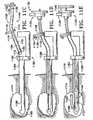
- Figures 1A-1Mshow various configurations of a preferred subcutaneous cavity marking device of the present disclosure.
- the marking device 100is displayed as having either a generally spherical body 102 ( Figure 1A ), a generally cylindrical body 104 ( Figure 1B ), or a multi-faced or irregular body 106 ( Figure 1C ).
- the bodymay assume a variety of shapes.
- the bodymay be constructed to have substantially curved surfaces, such as the preferred spherical 102 and cylindrical 104 bodies of Figures 1A and 1B , respectively.
- the bodymay have conical or ellipsoidal, etc. shapes as well.
- the bodymay have substantially planar surfaces, such as polyhedric (i.e. cubic, tetrahedral, etc.) or prismatic, etc. forms.
- the bodymay also have an irregular or random shape, in the case of a gel, combining features of various curved and planar surfaces.
- Body 106 of Figure 1Cis an example of such an irregular body shape.
- the particular body shapewill be chosen to best match to the biopsy cavity in which the device is placed.
- the body shapecan be chosen to be considerably larger than the cavity. Therefore, expansion of the device will provide a significant resistance against the walls of the cavity.
- the aspect ratio of the deviceis not limited to what is displayed in the figures.
- the cylindrical body 104may have a shorter or longer length as required.
- the generally spherical marker 150is located at or near the geometric center of the body. Such a configuration will aid the physician in determining the exact location of the biopsy cavity, even after the body degrades and is absorbed into the human or mammalian body.
- the ring-shaped markers 154 of Figure 1Bare generally aligned along the longitudinal axis 114 of body 104. Note that although the ring-shaped markers 154 are spatially oriented so that their longitudinal axes lie along the longitudinal axis 114 of the body 104, each marker may assume a wide variety of random or predetermined spatial orientations other than the aligned orientation seen in Figure 1C . It can be appreciated that a nonspherical marker such as marker 154 is useful in aiding a physician in determining the spatial orientation of the deployed inventive device.
- markers 150 and 154may reside in locations other than those demonstrated in Figures 1A-1C . It is, however, preferred that markers 150 and 154 dwell in a predetermined, preferably central, location and orientation in the device body so to aid the physician in determining the location and orientation of the biopsy cavity.
- the markers herein describedmay be affixed to the interior or on the surface of the body by any number of suitable methods.
- the markermay be merely suspended in the interior of the body (especially in the case where the body is a gel), it may be woven into the body (especially in the case where the marker is a wire or suture), it may be press fit onto the body (especially in the case where the marker is a ring or band), or it may affixed to the body by a biocompatible adhesive. Any suitable means to affix or suspend the marker into the body in the preferred location is within the scope of the present invention.
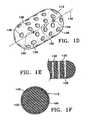
- Tissue regrowth in a particular orientationcan also be promoted by a body design shown in Figure 1D .
- body 110contains a number of pores 138 through which tissue may grow.
- the poresmay also be aligned in a substantially parallel fashion, traversing the thickness of the body so that tissue may regrow from one side of the body through to the other side.
- inset Figure 1Eshows a portion 130 of Figure 1D in partial longitudinal cross section, complete with pores 138 traversing through the thickness of portion 130.
- Such pores 138can be parallel to each other as shown in Figure 1E , or they may be perpendicularly, radially, or even randomly oriented in the device body.
- FIG. 1DA trio of markers is also shown in Figure 1D evenly aligned along the body longitudinal axis 140.
- Barb marker 156, spherical marker 150, and ring-shaped marker 154demonstrate the use of different multiple markers in a single body 110. As previously described, such a design helps a physician to determine the spatial orientation of the inventive device when it is deployed in a biopsy cavity.
- the barb marker 156is illustrated in a 'V' configuration, it is an important aspect of the barb marker 156 to have a shape that is clearly not spherical. This allows the barb marker 156 to be easily distinguished from calcifications that may be observed during any noninvasive imaging techniques.
- Figure 1Fdepicts a further embodiment of the present invention in which body 112 is enveloped in an outer shell 142 consisting of a layer of bioabsorbable material such those mentioned above.
- This configurationallows the perimeter of the biopsy cavity to be marked to avoid exposing the cavity, in the case of a "dirty" margin where re-excision may be necessary, to remaining cancerous cells as the tissue begins to re-grow into the cavity.
- a shell 142can be radiopaque and/or echogenic in situ, or it may be augmented with an additional coating of an echogenic and/or radiopaque material.
- the shell 142can also be made to be palpable so that the physician or patient can be further aided in determining the location and integrity of the implanted inventive device.
- Shell 142may be designed to have a varying bioabsorption rate depending upon the thickness and type of material making up the shell 142.
- the shellcan be designed to degrade over a period ranging from as long as a year or more to as little as several months, weeks, or even days. It is preferred that such a bioabsorbable shell be designed to degrade between two and six months; especially preferred is three months.
- interior 144 of body 112may be a cross-linked, collagenous material that is readily absorbed by the human or mammalian body once the shell 142 degrades. Interior 144 may be filled with a solid or gelatinous material that can be optionally made radiopaque by any number of techniques herein described.
- marker 150 in the device shown in Figure 1Fmay be permanently radiopaque or echogenic, or it may be bioabsorbable and optionally coated with a radiopaque and/or echogenic coating that degrades over a predetermined period of time. It is clinically important that the marker remain detectable for at least about one to five years so that the physician may follow the patient to ensure the health of the tissue in the vicinity of the biopsy cavity. Especially preferable is a marker whose radiopacity or echogenicity lasts between about one and three years.
- Each of the bodies depicted in Figures 1A-1Fmay be made from a wide variety of solid, liquid, aerosol-spray, powder, spongy, or expanding gelatinous bioabsorbable materials such as collagen, cross-linked collagen, regenerated cellulose, synthetic polymers, synthetic proteins, and combinations thereof. Also contemplated is a body made from a fibrin-collagen matrix, which further prevents unnecessary bleeding, and minimizes the possibility of hematoma formation.
- Examples of synthetic bioabsorbable polymers that may be used for the body of the deviceare polyglycolide, or polyglycolic acid (PGA), polylactide, or polylactic acid (PLA), poly ⁇ -caprolactone, polydioxanone, polylactide-co-glycolide, block or random copolymers of PGA and PLA, and other commercial bioabsorbable medical polymers.
- Preferredis spongy collagen or cellulose.
- materials such as hemostatic and pain-killing substancesmay be incorporated into the body and marker of the cavity marking device. The use of hemostasis-promoting agents provides an obvious benefit, as the device not only marks the site of the biopsy cavity but aids in healing the cavity as well.
- hemostatic agentshelp to avoid hematomas.
- hemostatic agentsmay include AVITENE Microfibrillar Collagen Hemostat; ACTIFOAM collagen sponge, sold by C. R. Bard Inc.; GELFOAM Sterile Powder or Sponge, manufactured by The Upjohn Company (Michigan); SURGICEL Fibrillar from Ethicon Endosurgery, Inc.; TISSEEL VH, a surgical fibrin sealant sold by Baxter Healthcare Corp.; Helistat collagen sponge from Integra Lifesciences; Helitene absorbable collagen hemostatic agent in Fibrillar form; and polyethylene glycol (PEG) or collagen/PEG compositions from Cohesion.
- Such agentsalso have the useful property of expanding between 3 and 30 times their compressed volume upon release into a cavity and/or upon hydration.
- the devicemay also be made to emit therapeutic radiation to preferentially treat any suspect tissue remaining in or around the margin of the biopsy cavity. It is envisioned that the marker would be the best vehicle for dispensing such local radiation treatment or similar therapy.
- the body itselfmay be adapted to have radiopaque, echogenic, or other characteristics that allow the body to be located by noninvasive technique without the use of a marker. Such characteristics permit the possibility of locating and substantially identifying the cavity periphery after deployment but prior to absorption of the device. Such an embodiment may allow delivery in liquid or gel form through a much smaller lumen than those marking devices having one of the markers previously described.
- an echogenic coatingmay be placed over the radiopaque marker to increase the accuracy of locating the marker during ultrasound imaging.
- the devicecan be deployed as a loosely wound ball or looped arrangement of bioabsorbable surgical material with a marker placed at the geometric center of the device.
- the materialmay be, for example, resilient suture material, that upon deployment into a tissue cavity provides resistance against the cavity wall and allows the marker to be located at substantially the center of the cavity.
- suture materialmay be looped through the band/ring 154; in such a configuration, the suture material acts as the body of the inventive device.
- the suturemay comprise a bioabsorbable material.
- the suture materialmay also have radiopaque, echogenic, or other characteristics described herein that aid in the noninvasive location of the device.
- the suture material 158is flexible to facilitate the expansion of the filler body to fill the cavity.
- the devicemay be in the form of multiple passes of suture material 158 looped through a marker 154 ( Figure 1G ).
- the suture materialmay also be configured in the form a pair of opposing loops 160 with a marker 154 between the loops 160 ( Figure 1H ), or two pairs of opposing loops 160 with the marker 154 in the center of the device ( Figure 1I ).
- the opposing loops 160may be bent longitudinally to form opposing members 162 ( Figures 1J, 1K ).
- the longitudinally bent opposing member 162may be, but is not necessarily, formed by applying heat to the suture to set the "bend".
- an aspect of this variationis that the opposing members 162 provide resistance against the walls of a delivery device, thereby, minimizing the possibility of the marking device being prematurely released from the delivery device.
- the resiliency of the suturewill expand the device and provide significant resistance against the walls of the cavity with the opposing members 162 providing additional resistance.
- Figures 1L and 1Millustrate preferred embodiments of the inventive tissue cavity marking device 182 and 184 each having an elongated body 178 or 180 with a circular or rectangular cross section and a metallic marker band 154.
- the metallic marker band 154preferably is oriented with its axis 174 perpendicular to the long axis 176 of the body 178 or 180 to allow maximum compression of the elongated body in the radial direction.
- the elongated bodies 178 and 180preferably comprise collagen-containing material with hemostasis-promoting properties.
- a marker 154(or any other marker) may be placed on the edge of a sheet of filler body material such as gelatin or collagen. The sheet may then be rolled or folded to form a device having an elongated body 178 or 180 having a circular or rectangular cross section. Alternatively, a block of collagen or other filler body material may be cut into a rectangular or cylindrical shape.
- a needlemay be used to create a hole through one end lengthwise, preferably only halfway through.
- a tube containing a marker such as marker 154may be placed into the hole created by the needle, and a plunger used to push the marker out of the tube and into the filler body, where it may be held in place by friction. Multiple markers may be used to help provide orientation when visualized in the patient on X ray, ultrasound, etc.
- One advantage of the collagen material and some of the other materials disclosed herein for the body of the marking deviceis that it can be easily cut with scissors, a knife, or a scalpel. Therefore, a physician can trim the body of the marking device to fit the cavity during the procedure. This is especially useful when creating the cavity and placing the marking device surgically. Furthermore, if re-excision in the same region is required, the surgeon will have no trouble cutting through the body of the marking device.
- FIGs 2A-2Gillustrate various forms of the marker 110.
- the marker 110may be a sphere 150 ( Figure 2A ), a hollow sphere 152 ( Figure 2B ), a ring or band 154 ( Figure 2C ), a barb 156 ( Figure 2D ), a flexible suture or flexible wire 158 ( Figure 2E ), or a crimped tube or a folded strip of material 172 ( Figure 2G ).
- the markermay have a distinguishing mark 170 ( Figure 2F ).
- the barb 156is illustrated in Figure 2D as having a "V" shape.
- the barb 156is intended to distinguish the marker from calcifications when viewed under noninvasive imaging techniques.
- the barb 156is not limited to the "V" shape; rather, it has a shape that is easily distinguishable from a spherical or oval calcification.
- the markeritself may aid in deploying the body.
- the markermay be made of a spring material such as superelastic nickel titanium alloy or stainless spring steel for delivery in compression to expand the body to substantially fill the cavity.
- the barb 156 of Figure 2D and the flexible wire 158 of Figure 2Eare particularly suited to mechanically aid deployment of the body (not shown).
- the hollow sphere 152 of Figure 2Bis more susceptible to detection by ultrasound than the solid sphere 150 of Figure 2A .
- spherical markerssuch as markers 150 and 152 can be beads of silicon or silicon-containing compounds, such as silicone or SiO 2 .
- the body of the cavity marking devicemay be woven or placed through the band or ring 154.
- the markermay also be a wire or suture 158 as shown in Figure 2E and as discussed in greater detail below.
- the marker 158may be affixed to the exterior perimeter of the body by an adhesive or woven through the body.
- the marker wire or suture 158being configured in a particular pattern within the body of the device, e.g., wrapping around the body in a helical manner. As described elsewhere, the wire or suture 158 may also be configured to comprise the body of the marking device.
- distinguishing or identifying mark 170can be in the form of simple marks as shown, or it may be one or more numbers, letters, symbols, or combinations thereof. These marks 170 are preferably located in more than one location on the marker 150 so that the marker may be readily and simply identified from multiple orientations under a variety of viewing conditions.
- Such a mark 170can be used to identify the patient and her condition, provide information about the marker and body of the tissue cavity marking device, provide information about the circumstances and date of the implantation, who performed the procedure, where the procedure was performed, etc. In the case of multiple biopsy sites, this distinguishing mark 170 permits one to differentiate and identify each different site.
- the mark 170may be applied via any number of techniques such as physical inscription, physical or plasma deposition, casting, adhesives, etc.
- the mark 170may also be an electronic chip providing any necessary information in electronic form that can be remotely detected by appropriate means.
- the marking devicemay use the device or technology of a Trovan Transponder (Electronic Identification Systems--Santa Barbara, California).
- Medical informationmay itself be directly encoded into the device, or a code on the device may be keyed to a corresponding record in a computerized database containing the medical information.
- the medical informationmay include such data as a pathology report of a biopsy sample taken from the site being marked, and this information may be entered into the computer record before or after implantation of the marking device. Furthermore, this information may be updated as needed.
- the mark 170may itself be remotely programmable to add patient or procedure information, pathology information, or the like after implantation in the body, although adding such capability to the marking device may increase its size.
- the markermay be radiopaque, echogenic, mammographic, etc. so that it can be located by noninvasive techniques.
- a featurecan be an inherent property of the material used for the marker.
- a coating or the likecan be added to the marker to render the marker detectable or to enhance its detectability.
- the markermay be made of a nonbioabsorbable radiopaque material such as platinum, platinum-iridium, platinum-nickel, platinum-tungsten, gold, silver, rhodium, tungsten, tantalum, titanium, nickel, nickel-titanium, their alloys, and stainless steel or any combination of these metals.
- mammographicwe mean that the component described is visible under radiography or any other traditional or advanced mammography technique in which breast tissue is imaged.
- the markercan alternatively be made of or coated with a bioabsorbable material.
- the markercan, for instance, be made from an additive-loaded polymer.
- the additiveis a radiopaque, echogenic, or other type of substance that allows for the noninvasive detection of the marker.
- radiopaque additiveselements such as barium- and bismuth-containing compounds, as well as particulate radiopaque fillers, e.g., powdered tantalum or tungsten, barium carbonate, bismuth oxide, barium sulfate, etc. are preferred.
- any component of the devicemay contain air bubbles or may be combined with an echogenic coating.
- ECHO-COATfrom STS Biopolymers.
- Such coatingscontain echogenic features, which provide the coated item with an acoustically reflective interface and a large acoustical impedance differential.
- an echogenic coatingmay be placed over a radiopaque marker to increase the accuracy of locating the marker during ultrasound imaging.
- the radiopacity and echogenicity described herein for the marker and the bodyare not mutually exclusive. It is within the scope of the present invention for the marker or the body to be radiopaque but not necessarily echogenic, and for the marker or the body to be echogenic but not necessarily radiopaque. It is also within the scope of the invention that the marker and the body are both capable of being simultaneously radiopaque and echogenic. For example, if a platinum ring marker were coated with an echogenic coating, such a marker would be readily visible under x-ray and ultrasonic energy. A similar configuration can be envisioned for the body or for a body coating.
- the markeris preferably large enough to be readily visible to the physician under x-ray or ultrasonic viewing, for example, yet be small enough to be able to be percutaneously deployed into the biopsy cavity and to not cause any difficulties with the patient. More specifically, the marker will not be large enough to be palpable or felt by the patient.
- FIG. 3AAnother useful version of the invention is shown in Figure 3A .
- the body members 302can individually or together take on a variety of sizes and shapes as discussed above depending on the characteristics of the biopsy cavity to be filled.
- the body members 302may uniformly or in combination be made of one or more materials suitable for use in a biopsy cavity as previously described.
- markers 318may traverse two or more body member segments through the interior of the body members 302 as shown in Figure 3A .
- markers 318are located substantially parallel to the longitudinal axis 320 of each right cylindrical body member 302 in their interior, connecting each body member 302 while marking their geometric center as between the markers.
- Such a marker 318may be used in conjunction with the other markers as described above and may also be accompanied by one or more additional markers arranged randomly or in a predetermined pattern to variously mark particular sections of the device.
- such a markermay, singly or in combination with other markers, be affixed on or near the surface of the sponge so as to mark the perimeter of the body member 302.
- marker 318when used in conjunction with other connecting markers, marker 318 need not necessarily connect each body member; it may be used solely to indicate the orientation or location of each individual sponge or the entire device, depending on the material, geometry, size, orientation, etc. of marker 318. When not used in this connecting function, therefore, marker 318 need not traverse two body members 302 as shown in Figure 3A .
- a marker 322can wrap around the body 302 in a helical pattern ( Figure 3B ), or it can be used in conjunction with other markers 324 in a pattern parallel to the longitudinal axis 320 of the body 302 ( Figure 3C ).
- Figure 3DAnother useful perimeter marking pattern is shown in Figure 3D , where marker segments 326 are affixed at or near the surface of the circular bases of the cylindrical body 302 in a cross pattern, indicating the ends of the sponge and their center.
- the marker(s)may, but do not necessarily, have some texture. Any marker pattern, internal or external to the body, is within the scope of the present invention.
- the markerbe a radiopaque or echogenic wire or suture.
- FIG. 3BAnother possible configuration is obtained by combining the suture or wire markers 158 in a body with any other type marker 150, 152, 154, or 156 or vice versa.
- a spherical marker 150may be placed in the center of the cylindrical body 302. Therefore, the cylindrical body 302 would contain the suture or wire marker 322 wrapped helically adjacent to the outer perimeter, and a marker 150 would be placed in the center of the cylindrical body 302.
- Such a combinationmay be obtained with any of the body and marker configurations as defined above.
- the markers 150 or 154may be substituted with one or more suture or wire markers 158, preferably extending through the center and pointing radially away from the center. This configuration allows marking of the cavity perimeter and establishing of the directionality of the cavity itself.
- any of the previously-described additional features of the inventive devicesuch as presence of pain-killing or hemostatic drugs, the capacity for the marker to emit therapeutic radiation for the treatment of various cancers, the various materials that may make up the marker and body, and their size, shape, orientation, and geometry, may be incorporated into the device described above in conjunction with Figures 3A-3D .
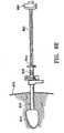
- Figure 4Adetails the marking device 402 just prior to delivery into a tissue cavity 404 of human or other mammalian tissue, preferably breast tissue 406.
- the step illustrated in Figure 4Ashows a suitable tubular percutaneous access device 400, such as a catheter or delivery tube, with a distal end 408 disposed in the interior of cavity 404.
- the marking device 402may be delivered percutaneously through the same access device 400 used to perform the biopsy in which tissue was removed from cavity 404. Although this is not necessary, it is less traumatic to the patient and allows more precise placement of the marking device 402 before fluid begins to fill the cavity 400.
- Figure 4Bshows marking device 402 being pushed out of the distal end 408 of access device 400 by a pusher 412 and resiliently expanding to substantially fill the tissue cavity 404.
- access device 400is withdrawn from the breast tissue, leaving marking device 402 deployed to substantially fill the entire cavity 404 with radiopaque or echogenic marker 410 suspended in the geometric center of the marking device 402 and the cavity 404.
- the marking device 402may be sized to be larger than the cavity 404 thus providing a significant resistance against the walls of the cavity 404.
- Figures 4D-4Fshow a method of delivering the marking device 402 into a tissue cavity 404 by a plunger 414 that is capable of both advancing the marking device 402 and delivering a biocompatible fluid 416.
- the "biocompatible fluid”is a liquid, solution, or suspension that may contain inorganic or organic material.
- the fluid 416is preferably a saline solution, but may be water or contain adjuvants such as medications to prevent infection, reduce pain, or the like. Alternatively or additionally, the fluid may be used to mark the sentinel lymph node. Obviously, the fluid 416 is intended to be a type that does no harm to the body.
- Figure 4Ddetails the marking device 402 prior to delivery into the tissue cavity 404.
- a plunger 414pushes the marking device 402 out of the access device 400.
- the marking device 402Upon exiting the access device 400 the marking device 402 begins resiliently expanding to substantially fill the cavity 404.
- Figure 4Fshows the plunger 414 delivering the biocompatible fluid 416 into the cavity 404.
- the plunger 414may be equipped with a Luer or other type fitting to attach a fluid reservoir or syringe (not shown).
- the fluid 416aids the marking device 402 in expanding to substantially fill the cavity 404.
- the biocompatible fluid 416is delivered subsequent to the placement of the marking device 402 in the cavity 404.
- the marking device 402may also be soaked with fluid 416 prior to placement in the cavity 404.
- the fluid 416may be delivered prior to delivery of the marking device 402.
- Figures 4G-4Ishow another method of delivering the marking device 402 into the tissue cavity 404 by using the biocompatible fluid 416 as the force to deliver the marking device 402 into the tissue cavity 404.
- Figure 4Gdetails the marking device 402 prior to delivery into the tissue cavity 404.
- Figure 4Hillustrates flow of the biocompatible fluid 416 in the access device 400, the fluid 416 flow then pushes the marking device 402 out of the access device 400.
- Figure 4Ishows the delivery device 400 continuing to deliver the biocompatible fluid 416 into the cavity 404.
- the fluid 416aids the marking device 402 in expanding to substantially fill the cavity 404.
- the biocompatible fluid 416is delivered after the placement of the marking device 402 in the cavity 404 although the invention is not limited to the continued delivery of the fluid 416.
- Figures 4J-4Lshow the method of delivering the body 418 of the cavity marking device directly into the cavity 404 prior to the placement of the marker 410 in the device 402.
- Figure 4Jshows the deposit of the body material 418 into the cavity 404.
- the body material 418may be a gel type material as described above.
- Figure 4Kdetails the filling of the cavity 404 with the body material 418.
- the delivery device(not shown in Figure 4K ) may be withdrawn.
- Figure 4Ldetails the placement of the marker 410 into the body material 418.
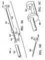
- Figures 5A-5Eshow yet another version of the invention in which a marker, preferably consisting of a radiopaque or echogenic wire, is deployed alone into a tissue cavity without the use of any body.
- the markercan be made of a shape memory material, such as a nickel-titanium alloy, which, when deployed into the biopsy cavity, assumes a predetermined configuration to substantially fill the cavity, mark the cavity location and margin, and indicate the orientation of the marker inside the cavity.
- the open design of these deployable markersallows tissue in-growth, that further stabilizes the markers.
- the periphery of the cavityis marked with a relatively small amount of implanted material.
- marker 500is a three-dimensional sphere consisting of two rings 502 and 504 pivotally connected at ends 506 and 508 so to assume a spherical shape.
- a markercan be made of a shape memory metal so that when it is placed in a deployment tube 510 shown in Figure 5B , marker 500 assumes a collapsed profile suitable for deployment through tube 510 by pusher 512.
- marker 500Upon exiting into the tissue cavity (not shown), marker 500 assumes the spherical shape of Figure 5A to fill the cavity.
- the marker 500may also be shaped into any similar shape such as an ellipsoidal shape.
- a marker 520 in the form of a wire cylinderis shown.
- this deviceis structurally configured to assume the depicted cylindrical configuration when deployed in the tissue cavity, but may be (as described above) "collapsed" into a deployment tube for percutaneous delivery.
- This deviceis especially suitable for marking the distal and proximal ends of the tissue cavity due to its asymmetrical shape.
- Figure 5Dshows a shape memory marker 530 in the form of a helical coil deployed into tissue cavity 532.
- a shape memory marker 530may be deployed through delivery tube 510 by pusher 512 in a substantially elongated, straightened form, only to substantially assume the shape of the cavity 532 as shown in Figure 5D .
- Any suitable delivery device or pusher 512 capable of deploying marker 530 into cavity 532is within the scope of this invention.
- Each of the markers shown in Figures 5A-5Eis preferably a shape memory material coated or supplemented with a radiopacity-enhancing material, such as gold, platinum, or any other radiopaque material herein discussed.
- the markersmay singly, or in combination with being radiopaque, be echogenic or be made echogenic by any of the materials or methods herein described.
- Each of the markers shown in Figures 5A-5Eis preferably self-centering. It is within the scope of the invention to add one or more materials such as a biocompatible liquid, gel, powder, or the like into the cavity before, during, or after delivery of those markers; the material may provide treatments such as hemostasis, antibiotic properties, or pain relief.
- a marker of any of the type shown in Figures 2A-2Gmay be inserted into the optional material to mark the center or provide patient information as described with respect to Figure 2F .
- Figures 6A-6Dshow a method of delivering the marking device 602 into a tissue cavity 604 that allows the marking device 602 to radially expand to substantially fill the cavity 604 without the need for simultaneous pushing of the marking device 602 into the cavity 604. While the marking device 602 depicted in Figures 6A-6D is depicted as a bioabsorbable surgical material with a marker placed at the geometric center of the device, the method is not limited to such devices. Any of the marker devices described herein may be used with this method.
- Figure 6Adetails insertion of a sheath 600 into communication with tissue cavity 604.
- the sheath 600is placed through the same access pathway (not shown) used by the biopsy device (not shown).
- the sheath 600is placed soon after the cavity 604 is formed.
- Figure 6Billustrates insertion of a cartridge or applicator 606 through the sheath 600 and into the cavity 604.
- the cartridge 606may contain a marking device 602 and a disengaging arm (not shown.)
- the cartridge 606is advanced into the cavity 604 until the marking device 602 is located within the cavity 604.
- Figure 6Cillustrates the withdrawal of the cartridge 606 from the cavity 604 and the partial expansion of the cavity marking device 602.
- the disengaging arm 608 within the cartridge 606permits withdrawal of the cartridge 606 independently of the marking device 602.
- the marking device 602remains within the cavity 604.
- the use of the disengaging arm 608permits the placement of the marking device 602 while allowing for a significant frictional fit between the marking device 602 and the cartridge 606. This frictional fit minimizes the possibility of accidental deployment of the marking device 602.
- Figure 6Dillustrates the withdrawal of the cartridge 606 and the disengaging arm 608 from the cavity 604 leaving the marking device 602 to radially expand into the cavity 604.
- fluidmay be delivered to the cavity 604 to assist the expansion of the marking device 602.
- the sheath 600 and cartridge 606are withdrawn from the cavity 604 and further withdrawn from the body.
- Figures 7A-7Kshow devices for delivering a marking device into a tissue cavity which allow the marking device to radially expand to substantially fill the cavity without the need for simultaneous pushing of the marking device into the cavity.
- Figure 7Aillustrates a variation of a disengagement arm 700 having distal 704 and proximal 702 ends.
- the disengagement arm 700 of this figurehas first and second slots 706 and 708 that allow for a cartridge 710 and sheath 716 to have fixable positions along the disengagement arm 700.
- the disengagement arm 700may be configured to have a lumen (not shown) to provide delivery of fluid to the cavity to assist with the expansion of the marking device (not shown).
- Figure 7Billustrates a variation of a cartridge 710 having a lumen 712 for placement of a marking device (not shown).
- the cartridge 710has an offset member 714 visible in Figure 7C .
- the offset member 714engages with the first slot 706 of the disengagement arm 700 to define a fixable position of the cartridge 710 along the disengagement arm 700.
- Figure 7Dillustrates a sheath 716 having an offset member 718, as shown in Figure 7E , which engages with the second slot 708 of the disengagement arm 700 to define a fixable position of the sheath 716 along the disengagement arm 700.
- the cartridge 710may be rotated about the disengagement arm 700 so that the offset member 714 is removed from the slot 706 allowing the cartridge 710 to be moved to the proximal end of the disengagement arm 700.
- Figure 7Fshows another variation of a disengagement arm 720 having distal 724 and proximal 722 ends.
- the disengagement arm 720 of this variationhas a stop 726 that allow for a cartridge 730 and sheath 736 to have fixable positions along the disengagement arm 720.
- Figure 7Gshows a variation of a cartridge 730 having a lumen 732 for placement of a marking device (not shown).
- the cartridge 730has a flange 734, as shown in Figure 7H , which rests against the stop 726 of the disengagement arm 720 to provide the cartridge 730 with a fixable position along the disengagement arm 720.
- the cartridge 730may be rotated about the disengagement arm 720 so that an opening 738 in the flange 734 allows the cartridge 730 to be moved to the proximal end of the disengagement arm 722.
- a sheathmay have a fixable position along the cartridge 730 as the sheath is placed against a proximal end 742 of the cartridge 730.
- Figure 7Ishows a variation of the sheath 736 for use with the disengagement arm 720 and cartridge 730 of Figures 7F and 7G .
- the disengagement arm 720may be configured to have a lumen (not shown) to provide delivery of fluid to the cavity to assist with the expansion of the marking device (not shown).
- Figure 7Jillustrates the variations of the cartridge devices against a proximal end of the disengagement arms 720 and 700.
- Figure 7Killustrates the variations of the cartridge devices in a fixable position along the disengagement arms 720 and 700. In these positions, the end portions 748 and 740 of the cartridges 720 and 700 extend beyond the distal ends 724 and 704 of the disengagement arms.
- Figures 8A-8Iillustrate a delivery device 800 and a method for using it to deliver a marking device 860 to a tissue cavity 874 accessed and/or made by the probe 882 of a medical instrument 880.
- the probe 882is preferably between 1 and 25 mm in its largest cross sectional dimension (diameter, if circular), and most preferably between 2 and 5 mm.
- the marking device 860is shown as the type shown in Figure 1K , it is not limited to such, and may be of any type disclosed in this application or any other type.
- the delivery device 800includes an outer sheath 810 having a proximal entryway 812 for the probe 882 (shown in Figure 8B ).
- the outer sheath 810further includes an outer sheath hub 814 and an optional side port 816.
- the outer sheath 810may be circular or noncircular in cross section regardless of whether the probe 882 has a circular or noncircular cross section. For example, if the outer sheath 810 is flexible and circular in cross section, but the probe 882 is shaped like a " figure 8 ", the outer sheath 810 may conform to follow the contours of the probe when the outer sheath is placed over the probe.
- the delivery device 800further includes an applicator 820, which is made up of an inner sheath 830 and a plunger 840.
- the inner sheath 830may further comprise an inner sheath hub 832, a safety lock 834 with a safety tab 835, a stop 836, and a distal portion 838 that is distal of the stop 836.
- a marking device 860may be preloaded within the distal portion 838 of the inner sheath 830.
- the inner sheath hub 832is preferably immovable on the inner sheath 830, providing both a grip for pushing the plunger 840 and a support for the safety lock 834. Furthermore, the inner sheath hub 832 may also function as a stop, thereby eliminating the need for separate stop 836.
- the distal portion 838 of the inner sheath 830is sized to fit through either the entryway 812 or the side port 816 of the outer sheath 810 up to the inner sheath stop 836.
- the delivery device 800preferably includes a guide 850 having a clamp 852 for attachment to a first point that is fixed with respect to a desired marking site within the patient.
- This first fixed pointcould be, for example, on the patient herself, on a stereotactic table, or on an attachment on a stereotactic table, such as a rail, a fixed portion of a driver attached to the stereotactic table, or the like.
- the guide 850has a channel 854 through which the outer sheath 810 may slide.
- the guide 850also has a locking mechanism 856 that can engage the outer sheath hub 814.
- the inner and outer sheathsare preferably made of Pebax, a fluoropolymer such as Teflon®, or polyethylene, and may be radiopaque or echogenic.
- the hubs 814 and 832 and guide 850are preferably made of polycarbonate or polypropylene.
- the outer sheath 810is placed over a probe 882 of a medical instrument 880, such as a biopsy probe.
- a guide 850preferably is attached, using a clamp 852, to a first point 858 that is fixed with respect to the patient 870, such as a fixed point on the medical instrument 880, a rail of a stereotactic table 890 (as shown), or the patient herself.
- the probe 882 with the outer sheath 810is introduced through the channel 854 of the guide 850, through the skin 872 of the patient 870, and into the site where the marker is to be deployed; this step may comprise taking a tissue sample, thus creating a cavity 874 in the tissue.
- the guide 850is moved from the first fixed point 858, then slid along the outer sheath 810 toward the outer sheath hub 814 to a second fixed point 859 along the rail of the stereotactic table 890.
- the second fixed point 859may be a point on the medical instrument 880 or the patient 870 or other convenient place to keep the outer sheath 810 stationary with respect to the patient 870 during delivery of the marking device.
- the guide 850is connected to the outer sheath hub 814, such as with a friction or snap fit of the locking mechanism 856.
- the medical instrument 880is then at least partly retracted from both the patient 870 and the stationary outer sheath 810, leaving the outer sheath 810 in communication with the biopsy cavity 874.
- the probe 882may be retracted just far enough to allow access to the cavity through the side port 816; the distal end of the probe 882, which is typically sharp, may remain protected by the proximal end of the outer sheath 810, and is not required to be retracted past the outer sheath entryway 812.
- the probe 882must be fully retracted to clear the entryway 812.
- the outer sheath 810may be rotated within the guide 850 to ensure that side port 816 is oriented to be accessible to the operator.
- an applicator 820comprising an inner sheath 830 and a plunger 840 preferably is inserted into a side port 816 of the outer sheath 810 until the stop 836 is reached and the distal end 831 of the inner sheath 830 protrudes through the distal end 818 of the outer sheath 810.
- the inner sheath 830is preferably flexible to bend to access the side port 816. Alternatively, it may be preshaped in a bend or curve to access the side port 816.
- plunger 840is flexible to access side port 816; it, too, may have a preshaped curve.
- the probe 882may be retracted clear of the proximal entryway 812, and the applicator 820 may be inserted through the proximal entryway 812.
- Figures 8G-8Iillustrate deploying the marking device 860.
- a safety lock 834is unlocked by depressing a safety tab 835 on the applicator 820 to release the plunger 840.
- the plunger 840is pushed into the inner sheath 830, as shown by the arrow in Fig. 8H , to deploy the preloaded marking device 860 into the tissue cavity 874, as shown in Fig. 8I .
- a Luer or other type fittingmay be provided on the delivery device for fluid infusion.
- the delivery device 800is removed from the patient 870.
- the delivery device of Figures 8A-8Imay be used to deliver a marking device to a surgically-created cavity by introducing the distal end of the outer sheath through the surgical incision and into the cavity.
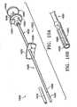
- Figures 9A-9Fillustrate a delivery device 900 and a method for using it to deliver a marking device 960 to a tissue cavity 974 laterally through a side window 986 of a cannula 982 of a medical instrument 980.
- the marking device 960is shown as the type shown in Figure 1K , it is not limited to such, and may be of any type disclosed in this application or any other type known in the art. It is preferably implantable without needing to be removed.
- the medical instrument 980may be a biopsy device as described above, or may be any other medical instrument having a cannula 982 with an entryway 988 through which the delivery device 900 can enter, a stop 984 that can limit travel of the delivery device 900, and a side window 986 proximate the distal end 985 through which the marking device 960 can be deployed.
- the probe 982is preferably between 1 and 25 mm in its largest cross sectional thickness (diameter, if circular), and most preferably has an inner diameter of 2.5 to 4 mm.
- the stop 984may completely or only partially block the distal end 985 of the cannula 982 or may be located elsewhere to limit travel of the delivery device 900.
- the delivery device 900preferably includes a shaft 920, which has a flexible shaft portion 930, a proximal handle portion 932, a rotational position indicator 934, and a cutout 936 in the proximal handle portion 932 for mating with a feature 989 of the medical instrument 980 (shown in Figure. 9C ).
- This feature 989may be the tip of a slidable rod that aids in ejecting a tissue sample from the medical instrument 980, which in this case is shown as a biopsy instrument.
- the flexible shaft portion 930is flexible enough in bending to allow it to be introduced through the entryway 988 of the cannula 982 of the medical instrument 980, yet stiff enough in compression to allow it to be pushed through the cannula 982.
- Distal of the flexible shaft portion 930is a distal shaft portion 938, comprising an ejector 940 having a seat 942 on which the preloaded marking device 960 (shown in Figure 9D ) rests prior to delivery and from which the marking device 960 is ejected laterally through the side window 986 of the cannula 982 (shown in Figure 9F ).
- the ejector 940further comprises one or more living hinges 944.
- the entire shaft 920 except for the proximal handle portion 932is sized to fit through the cannula 982 of the medical instrument 980 (shown in Figure 9E ), and is preferably molded or machined of only one material, such as polypropylene, nylon, or acetal (Delrin®).
- the flexible shaft portion 930is more flexible than the proximal portion of the ejector 940. This flexibility may be brought about by varying thickness (using a flexible shaft portion 930 that is thinner, or smaller diameter, if the shaft is round, than the thickness or diameter of the proximal portion of the ejector 940). Alternatively, this greater flexibility may be obtained by varying the shape of the cross section.
- this greater flexibilitymay be obtained by using a more flexible material for the flexible shaft portion 930 than for the proximal portion of the ejector 940.
- the section desired to be less flexiblemay be laminated with a stiff tubing.
- the cannula 982 of the medical instrument 980is introduced through the skin 972 of the patient 970 and into the site where the marking device 960 is to be deployed.
- this stepmay comprise taking a tissue sample, thus creating a cavity 974 in the tissue.
- the side window 986 and lumen of the cannula 982are then cleared of tissue debris, such as by applying a vacuum; additionally, the cannula may be flushed with saline, which is then aspirated.
- the shaft 920is preloaded with a marking device 960, which sits in the seat 942.
- the marking device 960is preferably held in place by a retainer 910, which may comprise a tube (as shown), a block, a clip, or the like.
- a retainer 910is a tube, it is preferably made of polyethylene teraphthalate (PET).
- PETpolyethylene teraphthalate
- the seat 942itself may be designed to provide substantial friction between it and the marking device 960 to help retain the marking device 960 within the seat 942.
- the retainer 910while preferable, is not essential.
- the friction between the marking device 960 and seat 942may be increased by adding texture to the surface of the seat 942 and/or by furnishing a seat of a size and shape to provide an interference fit between the marking device 960 and the seat 942.
- the distal end of the shaft 920is placed through the cannula entryway 988 and aligned so that the marking device 960 is in line with the side window 986.
- the rotational position indicator 934 in proximal handle portion 932aids in determining the orientation of the marking device 960.
- the retainer 910is a tube, block, clip, or the like
- the retainer 910may be transient as shown, sliding toward the proximal end of the shaft 920 as the delivery device 900 enters the cannula 982.
- the marking device 960remains captured between the seat 942 and the cannula 982 as the shaft 920 with marking device 960 is slid through the cannula 982. This differs from some of the prior art clipping devices that are carried on a wire that must be cut when the clip reaches its intended location.
- the shaft 920is advanced so that the distal end of the shaft 920 contacts the cannula stop 984. Advancement of the shaft 920 continues until the ejector 940 ejects the marking device 960 from the seat 942, through the cannula side window 986, and into the tissue cavity 974. As shown here, the ejection step may occur by buckling the shaft 920 in the region of the ejector 940, pushing the seat 942 toward the cannula side window 986. This may be facilitated by using one or more living hinges 944.
- a cutout 936 in the proximal handle portion 932may be mated with a mating feature 989 in the medical instrument 980 to indicate that the shaft 920 is in the correct position such that the ejector 940 has ejected the marking device 960.
- the ejector 940remains completely within the cannula 982 without any portion of it passing through the side window 986. This helps to ensure that the marking device 960 is delivered directly out of the side window 986 without pushing it to some unknown location further away.
- the retainer 910may comprise a tube having a slit 912 or other means of expanding its proximal end to fit over the proximal handle portion 932.
- the retainer 910preferably remains captured on the shaft 920 between the proximal handle portion 932 and the cannula entryway 988.
- the cannula 982preferably is rotated about 180° so that the side window 986 is away from the deployed marking device 960.
- the medical instrument 980 and delivery device 900are then retracted from the patient 980.
- the ejector 940is designed to substantially cover the window 986 of the medical instrument 980 to prevent drag on and/or injury to tissue or the marking device on the way out.
- Figures 10A-10Hillustrate an alternative delivery device 1000 and method for using it to deliver a marking device 1060 to a tissue cavity 1074 laterally through the side window 1086 of a cannula 1082 of a medical instrument 1080.
- the delivery device 1000is similar to that of delivery device 900 in that its main features are (1) an ejector seat for holding and ejecting a marking device laterally through a side window while remaining within the cannula and (2) a flexible shaft for pushing the ejector seat and marking device through the cannula.
- the medical instrument 1080may be a biopsy device as described above, or may be any device having a cannula 1082 with an entryway 1088 through which the delivery device 1000 can enter, and a side window 1086 proximate the distal end 1085 through which the marking device 1060 can be deployed.
- the cannula 1082, and therefore the portion of the delivery device sliding through cannula 1082is preferably between 1 and 25 mm in its largest cross sectional thickness (diameter, if circular), and most preferably has an inner diameter of 1.5 to 4.5 mm.
- cannula 1082has an inner diameter of about 2.7 mm, allowing delivery of a marking device 1060 having a compressed diameter of about 2.5 mm.
- the marking device 1060is shown as the type shown in Figure 1L , it is not limited to such, and may be of any type disclosed in this application or any other type known in the art.
- the marking device 1060is preferably one that can be simply released into the marking site without requiring clipping or piercing tissue.
- the delivery device 1000includes an applicator 1020, which has a sheath 1030 and a plunger 1040.
- a portion of sheath 1030 and a portion of plunger 1040together form a flexible shaft portion 1022, which can bend to fit through entryway 1088 and is rigid enough to push the ejector seat with its marking device through the cannula 1082.
- the sheath 1030further comprises a proximal handle portion 1032 and a collapsible sleeve 1031 at or near its distal end. As shown in Fig.
- sleeve 1031forms an ejector seat 1033, preferably U-shaped, in its collapsed condition on which the preloaded marking device 1060 rests prior to delivery and from which the marking device 1060 is ejected through the side window 1086 of the cannula 1082 (shown in Fig. 10C ).
- the sleeve 1031is preferably made of a high yield strength plastic such as PET, polyimide, polycarbonate, or acrylic, and is preferably of a size and shape that the material does not have to yield when expanding to eject the marking device 1060.
- the sleeve 1031 and distal portion of the sheath 1030are sized to fit through the cannula 1082 of the medical instrument 1080 (shown in Figure 10C ).
- the sheath 1030further comprises a clip 1035 that is preferably immovable on the sheath 1030, and includes one or more features 1036, such as a notch, indentation, recess or hole, to mate with a feature 1089 on the medical instrument 1080 (shown in Fig. 10C ).
- the sheath 1030is preferably made of Pebax, a fluoropolymer such as Teflon®, or polyethylene, and is preferably radiopaque and/or echogenic.
- the clip 1035is preferably made of polycarbonate or polypropylene.
- the plunger 1040further comprises a proximal handle portion 1042 and a piston 1045 and is capable of expanding the sleeve 1031 by filling it with an expander 1044, which may be a fluid, such as saline or air, or preferably a solid, such as the distal portion of the piston 1045 as shown.
- an expander 1044which may be a fluid, such as saline or air, or preferably a solid, such as the distal portion of the piston 1045 as shown.
- the sleeve 1031may be sealed to form a balloon that keeps the fluid within the delivery device.
- the sleeve 1031may have one or more openings (not shown) to allow the fluid to not only expand the sleeve 1031 but to be delivered to the body; this is useful for delivering fluids having hemostatic, pain-reducing, antibiotic, sentinel node-detecting, and/or body-expanding properties; the body expanding properties may work by hydrating or by chemically reacting with the body material.
- the plunger 1040may further include a Luer or other type fitting for connection to a fluid reservoir or syringe (not shown). Additionally or alternatively, fluids may be infused through a vacuum system on the medical instrument. In the case where the expander 1044 is a solid, the sleeve 1031 may be open or closed.
- the cannula 1082 of the medical instrument 1080is introduced into the site where the marking device 1060 is to be deployed; as described before, this step may comprise taking a tissue sample, thus creating a cavity 1074 in the tissue.
- the side window 1086 and lumen of the cannula 1082are preferably cleared of tissue debris, such as by applying a vacuum; additionally, the cannula may be flushed with saline, which is then aspirated.
- the applicator 1020is preloaded with a marking device 1060, which sits in the ejector seat 1033 formed in the collapsed sleeve 1031. It is held in place by a retainer 1010, which may be a tube (as shown), a block, a clip, or the like, of a size that will not pass through the cannula 1082.
- the distal end of the applicator 1020is placed through the cannula entryway 1088 and aligned so that the marking device 1060 is in line with the side window 1086.
- This alignmentcan be achieved by ensuring that the side window 1086 is in its "12 o'clock" rotational position, as shown, and orienting the marking device 1060 so that it is facing the same direction as the side window 1086 and so that the clip 1035 with its mating feature(s) 1036 will match up with the feature 1089 on the medical instrument 1080.
- the retainer 1010cannot pass through the cannula 1082, it is a transient retainer and does not remain in place to hold the marking device 1060 in seat 1033; as the delivery device 1000 enters the cannula 1082, the retainer 1010 is slid off the marking device 1060 and remains outside the cannula 1082.
- the marking device 1060remains captured between the seat 1033 and the cannula 1082 as the applicator 1020 with its marking device 1060 is slid through the cannula 1082.
- the applicator 1020is advanced until the clip 1035 on the sheath 1030 abuts the proximal end of the retainer 1010, thus capturing the retainer 1010 between the clip 1035 and the cannula entryway 1088.
- the clip 1035is then clipped onto the medical instrument 1080 by mating the clip and medical instrument features, 1036 and 1089.
- the plunger 1040is then pushed until the expander 1044 expands the sleeve 1031, ejecting the marking device 1060 from the seat 1033, through the cannula side window 1086, and into the tissue cavity 1074.
- the cannula 1082is preferably rotated about 180° so that the side window 1086 is away from the deployed marking device 1060. This guarantees that only a smooth, non-cutting side of the cannula faces the marking device 1060 during withdrawal of the medical instrument 1080 to avoid dislodging the marking device 1060.
- an advantage of this systemis that once the sleeve is expanded it substantially covers the side window thus protecting the tissue.
- prior art through-cannula clip delivery devicestypically require extra steps of withdrawing the clip applier and reinserting an inner cannula to protect the tissue from the sharp window and to avoid dislodging the clip.
- the medical instrument 1080 and delivery device 1000are then retracted from the patient 1070.
- Figures 11A-11Eillustrate an alternative delivery device 1100 and method for using it to deliver a marking device 1160 to a tissue cavity 1174 laterally through the side window 1186 of a cannula 1182 of a medical instrument 1180.
- the medical instrument 1180is preferably a biopsy device as described above, or may be any device having a cannula 1182 with an entryway 1188 through which the delivery device 1100 can enter, and a side window 1186 proximate the distal end 1185 through which the marking device 1160 can be deployed.
- the marking device 1160is preferably the type shown in Figure 1L , it is not limited to such, and may be of any type disclosed in this application or any other known in the art. Marking device 1160 is preferably implantable and can be left in the body indefinitely.
- the delivery device 1100includes an applicator 1120, which has a sheath 1130 and a plunger 1140.
- a portion of the sheath 1130 and a portion of the plunger 1140together form a form a flexible shaft portion 1122, which can bend to fit through entryway 1188 and is rigid enough to push the ejector seat with its marking device through the cannula 1182.
- the sheath 1130further comprises a proximal handle portion 1132 and a collapsible sleeve 1131 that forms an ejector seat 1133 in its collapsed condition (similar to seat 1033 shown in Fig.
- the sleeve 1131is preferably made of a high yield strength plastic such as PET, polyimide, polycarbonate, or acrylic, and is preferably of a size and shape that the material does not have to yield when expanding to eject the marking device 1160.
- the sheath 1130further comprises a clip 1135 that is immovable thereon, having a clip feature 1136.
- the plunger 1140further comprises a proximal handle portion 1142 and a piston 1145 and is capable of expanding the sleeve 1131 by filling it with an expander 1144, which may be a fluid, such as saline or air, or preferably a solid, such as the distal end of piston 1145 as shown.
- an expander 1144which may be a fluid, such as saline or air, or preferably a solid, such as the distal end of piston 1145 as shown.
- the expander 1144is a fluid
- the sleeve 1131is sealed to form a balloon.
- the sleeve 1131may have one or more openings (not shown) to allow the fluid to not only expand the sleeve 1131 but to be delivered to the body; this is useful for delivering fluids having hemostatic, pain-reducing, antibiotic, sentinel node-detecting, and/or body-expanding properties; the body expanding properties may work by hydrating or by chemically reacting with the body material.
- the sleeve 1131may be open- or closed-ended.
- a separate fittingmay be provided on the sheath 1130 for drug or saline infusion through the sheath 1130.
- the distal end of the applicator 1020is sized to fit through the cannula 1182 of the medical instrument 1180 (shown in Figure 11C ).
- the delivery device 1100further includes a retainer 1110 having a key on its distal end for locking into a keyway 1183 in the cannula 1182 (shown in Fig. 11B ).
- the retainer 1110further includes a hub 1114 at or near its proximal end with a feature 1115 for connecting to the clip feature 1136 on the sheath clip 1135.
- the cannula 1182 of the medical instrument 1180is introduced into the site where the marking device 1160 is to be deployed; as described before, this step may comprise taking a tissue sample, thus creating a cavity 1174 in the tissue.
- the side window 1186 and lumen of the cannula 1182are preferably cleared of tissue debris, such as by applying a vacuum; additionally, the cannula may be flushed with saline, which is then aspirated.
- the applicator 1120is preloaded with a marking device 1160, which sits in the seat 1133 (see seat 1033 in Fig. 10B ) formed in the collapsed sleeve 1131.
- the retainer 1110which may be a tube (as shown), a block, a clip, or the like.
- the side window 1186 of the cannula 1182it is not necessary that the side window 1186 of the cannula 1182 be in its "12 o'clock" position to align the marking device 1160 with the side window 1186.
- the keyway 1183rotates with the cannula 1182, and therefore is in line with the side window 1186.
- the distal end of the applicator 1120 and retainer 1110are placed through the cannula entryway 1188 and aligned so that the retainer key 1112 enters keyway 1183 of the cannula 1182.
- the retainer 1110is slid off the marking device 1160.
- the applicator 1020is pushed forward, aligning the feature 1136 in the sheath clip 1135 with the feature 1115 in the retainer hub 1114 and connecting them together, thus capturing the retainer 1110 between the cannula entryway 1188 and the sheath clip 1135.
- the marking device 1160By locking the sheath clip 1135 to the retainer hub 1114, and because the retainer 1110 is locked into the keyway 1183 and is therefore rotationally fixed with respect to the cannula 1182, the marking device 1160 will always face the direction that the side window 1186 is facing. Therefore, the marking device 1160 may be delivered when the medical instrument 1180 has its cannula 1182 and side window 1186 in any clock position, and is not limited to delivering in only the 12 o'clock position. The marking device 1160 remains captured between the seat 1133 and the cannula 1182 as the applicator 1120 with its marking device 1160 is slid through the cannula 1182.
- the safety lock 1134 on the proximal handle portion 1132is then unlocked, and the plunger 1140 is pushed until the expander 1144 expands the sleeve 1131, ejecting the marking device 1160 from the seat 1133, through the cannula side window 1186, and into the tissue cavity 1174.
- all parts of the applicator 1120 that enter the cannula 1182remain completely within the cannula 1182 without any portion passing through the side window 1186. This helps to ensure that the marking device 1160 is delivered directly out of the side window 1186 without pushing it to some unknown location further away.
- an advantage of delivery device 1100is that once the sleeve is expanded it substantially covers the side window 1186 thus protecting the tissue.
- the medical instrument 1180 and delivery device 1100are then retracted from the patient 1170.
- the inventionprovides an improved subcutaneous cavity marking device and method. While the above descriptions have described the invention for use in the marking of biopsy cavities, the invention is not limited to such. One such application is evident as the invention may further be used as a lumpectomy site marker. In this use, the cavity marking device yields an improved benefit by marking the perimeter of the lumpectomy cavity. Other such applications of the invention include delivering a marker to a naturally occurring body cavity and delivering a marker to an area of tissue that does not have a cavity.
- the marking devicemay be delivered by hand without the use of a delivery system, and the marking device may not require compression for delivery through a small opening.
- the marking systemmay be provided as a kit, wherein the marking device is preloaded in the delivery device; alternatively, the marking device may be provided separately for loading into the delivery device by the operator, with or without the aid of a loading tool, which also may be provided in the kit.
- the kitmay be provided with variously sized and/or variously shaped marking devices, allowing the operator to choose the particular device most suited for the cavity to be marked. Having more than one marking device available in the kit also allows the operator to mark more than one location, if needed.
- the present inventionprovides an alternative composition and method to remotely detect sentinel lymph nodes to determine whether cancerous cells have spread thereto.
- This methodincludes the deposition, preferably by one of the delivery devices described herein or by injection via a thin needle applicator, of a remotely detectable contrast agent that migrates to the SN.
- the remotely detectable contrast agentallows a physician to pinpoint the location of the SN to target the SN for removal using minimally invasive techniques.
- the compositionis preferably capable of migrating from breast tissue to a lymph node in a predetermined amount of time. Preferably, less than 3 hours, and more preferably within 5 to 20 minutes.
- the contrast agentpreferably comprises particles between 0.05 microns and 5 microns in diameter.
- the composition and methodeliminates the need for potentially toxic radioactive tracer material. In addition, the lack of toxicity of such agents obviates the need to remove the lesion and/or the SN on the same day.
- the contrast agentis preferably either permanently implantable or short-lived, never requiring removal.
- agentsmay be any biologically compatible agents capable of remote detection.
- remote detectioninclude, but are not limited to, magnetism such as a magnetometer, Hall effect sensor, or magnetic resonance imaging (MRI); ultrasound; X ray, fluoroscopy, or CT; thermal means; high intensity ultraviolet techniques; fluorescent dye techniques; etc.; singly or in combination.
- a contrast agentis an echogenic microsphere capable of reflecting ultrasonic energy.
- These microspherespreferably averaging typically between 0.2 microns and 5 microns in diameter, and preferably less than 2 microns in diameter, may be mixed with a biologically compatible carrier fluid and injected into the body in the vicinity of the lesion, where they will accumulate in the SN.
- the echogenic microspheresmay comprise hollow bubbles fill with air, CO 2 , nitrogen, or fluorinated gas.
- these microbubblesmay comprise microencapsulated perfluorocarbon.
- the echogenic contrast agentmay, but does not necessarily, contain microparticles of silicon or a silicon compound, such as silicone or SiO 2 , preferably in a dilute suspension.
- a biologically compatible magnetically detectable bodysuch as a magnetic microsphere.
- a magnetically detectable bodycan be the echogenic microsphere described above that is either fabricated from or coated with a magnetic material; alternatively, it may be a solid or other type of magnetic body capable of being incorporated into a carrier fluid and deposited around the lesion or its cavity as described herein.
- These bodiesshould be capable of migration to and accumulation in the SN so that, in a similar fashion to the echogenic microspheres, the cumulative magnetic field presented by these magnetic bodies allows one to remotely and noninvasively determine the location of the SN.
- the contrast agentmay have sufficient radiopacity to be detectable using fluoroscopy, mammography, or other X ray imaging.
- Figures 12A-12Cshow a method for locating the sentinel lymph node in a mammalian body to determine if cancerous cells have spread thereto.
- the methodincludes (1) depositing a remotely detectable fluid in or around a lesion for migration to and accumulation in the associated sentinel node and (2) remotely detecting the location of that node with a minimum of trauma and toxicity to the patient.
- the composition used for locating the sentinel nodeis preferably a fluid composition consisting of a carrier fluid and some type of non-radioactive contrast agent as described above.
- the contrast agentmay also be a fluid and therefore not require a separate carrier fluid to migrate to the node.
- compositionis capable of (1) deposition in or around a lesion and migration to and accumulation in the associated sentinel node, and (2) remote detection a noninvasive technique.
- the compositionmay additionally be capable of being directly visualized such as by adding blue dye to the noninvasively-detectable contrast agent to confirm that the appropriate lymph node was removed.
- Carbonmay be, but is not necessarily, added to the contrast agent for histological confirmation.
- Figure 12Adepicts the first steps of a method for locating a sentinel node 1200 comprising injecting a noninvasively detectable, non-radioactive, migratory contrast agent 1210 into the region of a cavity or lesion 1220, then waiting sufficient time for the contrast agent to migrate through the lymph ducts 1230 to at least one lymph node 1200 in the axillary region 1250.
- the smaller the particle size of the contrast agentthe faster it will migrate; also, generally less viscous compositions will migrate faster.
- the closer in the size the particles are to each otherthe narrower the window of time will be for most of the particles to reach the sentinel node.
- the particlesmay be filtered or otherwise selected to be very close in size; alternatively, they may vary widely; as another alternative, they may have a bimodal size distribution with the smaller size for early sentinel node detection and the larger size for accumulation throughout the lymph nodes, as will be described below.
- the contrast agentmay be injected directly into a biopsy or lumpectomy cavity; or it may be injected intradermally or periareolarly (around the area of the areola 1240), before, after, or without creation of a cavity. While waiting for the contrast agent to migrate, massage and/or compression may be administered to the patient to speed migration of the contrast. Also, a biopsy or lumpectomy may be performed during the waiting period, if not already done (not shown). This latter order of steps may be preferred by some who believe that creating the cavity may disturb the lymph ducts 1230, slowing down or preventing migration of the contrast agent to the sentinel node.
- the contrast agent 1210is noninvasively detected in at least one lymph node 1200.
- non-invasive detection methodsinclude, but are not limited to using ultrasound, fluoroscopy, MRI, a Hall Effect sensor or magnetometer, or other imaging means.
- the contrast agent 1210is echogenic, and an ultrasound probe 1260 is used to scan the axilla 1250 while watching the ultrasound monitor 1270.
- the contrast agentmay accumulate in 2 or 3 lymph nodes almost simultaneously, with up to 3 being considered “sentinel nodes", as shown.
- contrast agents having a low viscosity and a uniformly small sizesuch as an average of less than 0.05 microns and an upper limit of 0.1 microns.
- lymphatic systemwill quickly take up the contrast agent.
- the contrast agentwill then quickly migrate to the sentinel node, then to the next node and so on. In that case, the physician must be careful to not wait too long between injection and detection.
- lymph tissue containing the contrast agent 1200is then either sampled, using fine needle aspiration (FNA) or core biopsy, or completely removed, percutaneously, endoscopically, laparoscopically, or using conventional surgery.
- a percutaneous tissue removal device 1280may be used, such as those described in U.S. Patents 5,913,857 and 5,810,806 and U.S. Applications 09/184,766 and 09/145,487 to Vivant Medical, Inc.
- the tissue sampling or removalis preferably done using ultrasound, especially in the case where ultrasound is used to detect the contrast agent.
- the ultrasound probe 1260held over the sentinel node 1200 that was detected in the axilla 1250 while the marked tissue is sampled.
- the tissue sampling or removalmay be done using fluoroscopy, especially in the case where the contrast agent is radiographic.
- the tissue sampling or removalmay be done using MRI.
- Many of the prior-art radioactive tracer methodsrequired separate procedures for detecting the sentinel node under the skin, marking the location on the skin with a dot, alternating between a gamma probe and an ultrasound probe to mark the SN with a wire, then surgically removing the SN and wire.
- the patientmay be noninvasively checked to see whether all the contrast was removed.
- it is preferable that the contrastbe completely implantable, not requiring removal.
- many of the commercially-available echogenic contrast agents suitable for this methodare short-lived, and therefore do not require removal.
- the removed tissueis evaluated histologically for cancer. If cancer is found in the sentinel lymph node, the migrating and accumulating properties of the contrast agent can be used to determine where additional lymph nodes are that should be removed. That is, the contrast agent that was used to detect the SN can be one that accumulates quickly in the first node ("sentinel node") for identification within preferably 5 to 20 minutes. The agent will continue to migrate through the lymphatic system, but preferably more slowly, with a portion of the contrast agent accumulating in each lymph node for detecting during a window of approximately I day to 1 month following injection. This facilitates detection of additional lymph nodes that the physician may want to remove in the case where cancer is detected in the sentinel node. Removing such lymph nodes may be therapeutic by decreasing the tumor burden, thus increasing the efficacy of subsequent chemotherapy.
- the lymph nodespreferably are removed percutaneously using image guidance of the same modality used to detect them.
- Figures 13A-13Bshow a method for marking a biopsy or lumpectomy cavity and locating the sentinel lymph node that had served the tissue removed from the cavity to determine if cancerous cells have spread thereto.
- the composition for locating the sentinel lymph nodeis preferably a fluid composition consisting of a carrier fluid and some type of contrast agent as described above; alternatively, the contrast agent may itself be a fluid and therefore not need a separate carrier fluid.
- This compositionis capable of (1) deposition in or around a lesion and migration to and accumulation in the associated sentinel node, and (2) detection, preferably by noninvasive means, and/or by direct visualization.
- Figure 13Adepicts the first steps of a method for marking a biopsy or lumpectomy cavity 1315 in the breast 1313 and locating a sentinel node 1300 in the axilla 1350, comprising inserting a subcutaneous marking device 1312 according to the present invention and using a delivery device 1305 according to the present invention.
- a contrast agent 1310is included in the marking device 1312, either as the body of the marking device (as shown), which may degrade, allowing detectable microparticles to migrate to the lymph nodes.
- the contrast agent 1310as a separate composition that is added to the marking device, before, during, or after its insertion into the cavity (e.g., see Figures 4D-4I , 10A-10H, and 11A-11E ).
- massage and/or compressionmay be administered to the patient to speed migration of the contrast.
- the contrast agentis noninvasively detected in at least one lymph node.
- non-invasive methodsincludes, but are not limited to, ultrasound, fluoroscopy, MRI, or a Hall Effect sensor or magnetometer, or other imaging.
- the imaging used to detect the contrast agentmay be, but is not necessarily, the same as that used to detect the cavity marking device.
- lymph tissue containing the contrast agentis then either sampled, using fine needle aspiration (FNA) (shown here) or core biopsy, or completely removed, endoscopically, laparoscopically, or using conventional surgery.
- marking device 1312has expanded to fill cavity 1315.
- Some of the contrast agent 1310has migrated away from the marking device 1312 and has accumulated in the sentinel node 1300, where an ultrasound probe 1360 is used to guide a needle 1390 for fine needle aspiration.
- the tissue sampling or removalmay be done using ultrasound, fluoroscopy, MRI, or any other suitable imaging technique.
- the contrast agentmay be visible under direct visualization, and the tissue may be surgically removed without any image guidance.
- the contrast agentmay be a radioactive tracer, and a gamma probe and/or lymphoscintigraphy may be used in combination with ultrasound, as described above, to detect and remove the sentinel node.
- a percutaneous tissue removal devicemay be used, such as those described in PCT publication WO 99/25248 ; U.S. Patents 5,913,857 and 5,810,806 ; and U.S. Applications 09/184,766 and 09/145,487 to Vivant Medical, Inc.
- the tissue sampleis evaluated for the presence of cancer. If cancer is found in the sentinel lymph node, the contrast agent can again be used to determine where additional lymph nodes are that should be removed.
- a contrast agentcan be used that will accumulate quickly in the first node (“sentinel node") for identification within preferably 5 to 20 minutes. The agent will continue to migrate through the lymphatic system, but more slowly, with a portion of the contrast agent accumulating in each lymph node for detecting during a window of approximately 1 day to 1 month following injection. This provides an easy way to detect the additional lymph nodes that may need to be removed in the case where cancer is detected in the sentinel node.
- the lymph nodespreferably are removed using image guidance of the same modality used to detect them.
Landscapes
- Health & Medical Sciences (AREA)
- Life Sciences & Earth Sciences (AREA)
- Biomedical Technology (AREA)
- Engineering & Computer Science (AREA)
- Public Health (AREA)
- Nuclear Medicine, Radiotherapy & Molecular Imaging (AREA)
- Animal Behavior & Ethology (AREA)
- General Health & Medical Sciences (AREA)
- Veterinary Medicine (AREA)
- Biodiversity & Conservation Biology (AREA)
- Oncology (AREA)
- Optics & Photonics (AREA)
- Epidemiology (AREA)
- Physics & Mathematics (AREA)
- Surgery (AREA)
- Pathology (AREA)
- Oral & Maxillofacial Surgery (AREA)
- Heart & Thoracic Surgery (AREA)
- Medical Informatics (AREA)
- Molecular Biology (AREA)
- Medicines Containing Antibodies Or Antigens For Use As Internal Diagnostic Agents (AREA)
- Surgical Instruments (AREA)
- Media Introduction/Drainage Providing Device (AREA)
- Magnetic Resonance Imaging Apparatus (AREA)
- Catching Or Destruction (AREA)
Abstract
Description
3,592,185 7/1971 Frei et al. Ferromagnetic Contrast Media and Method of Use 4,087,791 5/1978 Lemberger Electromagnetically Responsive Device and System for Detecting the Same 4,541,438 9/1985 Parker et al. Localization of Cancerous Tissue by Monitoring Infrared Fluorescence Emitted by Intravenously Injected Porphyrin Tumor-specific Markers Excited by Long Wavelength Light 4,735,210 4/1988 Goldenberg Lymphographic and Organ Imaging Method and Kit 4,735,796 4/1988 Gordon Ferromagnetic, Diamagnetic or Paramagnetic Particles Useful in the Diagnosis and Treatment of Disease 5,041,826 8/1991 Milheiser Identification System 5,101,827 4/1992 Goldenberg Lymphographic and Organ Imaging Method and Kit 5,114,703 5/1992 Wolf et al. Percutaneous Lymphography Using Particulate Fluorocarbon Emulsions 5,300,120 4/1994 Knapp et al. Implant with Electrical Transponder Marker 5,437,279 8/1995 Gray Method of Predicting Carcinomic Metastases 5,482,040 1/1996 Martin, Jr. Biostaging of Adenocarcinomas Utilizing Radiolabeled Tumor-associated Glycoprotein Antibodies 5,496,536 3/1996 Wolf Percutaneous Lymphography 5,114,703 5/1992 Wolf et al. Percutaneous Lymphography Using Particulate Fluorocarbon Emulsions 5,555,885 9/1996 Chance Examination of Breast Tissue Using Time-resolved Spectroscopy 5,579,766 12/1996 Gray Method of Predicting Carcinomic Metastases 5,582,172 12/1996 Papisov et al. System of Drug Delivery to the Lymphatic Tissues 5,595,177 1/1997 Mena et al. Scintigraphy Guided Stereotaxic Localizations Apparatus for Breast Carcinomas 5,674,288 10/1997 Knapp et al. Implant with Transponder Marker 5,697,902 12/1997 Goldenberg Method for Imaging and Treating Organs and Tissues 5,716,407 2/1998 Knapp et al. Method of Rendering Identifiable a Living Tissue Implant Using an Electrical Transponder Marker 5,725,578 3/1998 Knapp et al. Temporary Implant with Transponder and Methods for Locating and Identifying 5,732,704 3/1998 Thurston et al. Radiation Based Method Locating and Differentiating Sentinel Nodes 5,776,093 7/1998 Goldenberg Method for Imaging and Treating Organs and Tissues 5,776,094 7/1998 Goldenberg Method and Kit for Imaging and Treating Organs and Tissues 5,803,913 9/1998 Khalkhali et al. Nuclear Medicine Stereotaxic Localization Apparatus for Breast Carcinomas and Method 5,810,806 9/1998 Ritchart et al. Methods and Devices for Collection of Soft Tissue 5,855,609 1/1999 Knapp Medical Information Transponder Implant and Tracking System 5,857,463 1/1999 Thurston et al. Remotely Controlled Apparatus and System for Tracking and Locating a Source of Photoemissions 5,868,778 2/1999 Gershony et al. Vascular Sealing Apparatus and Method 5,895,640 4/1999 Khalkhali Nuclear Medicine Techniques for Detecting Carcinoma in the Dense Breast 5,899,865 5/1999 Chance Localization of Abnormal Breast Tissue Using Time-resolved Spectroscopy 5,913,857 6/1999 Ritchart et al. Methods and Devices for Collection of Soft Tissue 5,970,986 10/1999 Bolz et al. Apparatus for Rejection Diagnostics after Organ Transplants 5,977,431 11/1999 Knapp et al. Living Tissue Implant with Electrical Transponder Marker WO 98/09247 3/1998 Cothren et al. System and Method for Staging Regional Lymph Nodes Using Quantitative Analysis of Endoscopic Ultrasound Images WO 98/43090 10/1998 Werenskiold InVitro Method for Prognosis of the Illness Evolution of Patients with Carcinoma of the Breast and/or for Diagnosing Carcinoma of the Breast WO 98/52616 11/1998 Kresse et al. Nonsteroidal Antirheumatic Agents or Thrombocyte-Agglutination Inhibitors to Improve Representation of Vessels, Lymph Nodes and Bone Marrow with Pharmaceutical Preparations Containing Particles, Vesicles of Polymers WO 98/52617 12/1998 Mcintire Contrast Media WO 99/25248 5/1999 Carroll Minimally Invasive Surgical Probe for Tissue Identification and Retrieval and Method of Use WO 99/46284 9/1999 Rajotte et al. Molecules that Home to Various Selected Organs or Tissues - This invention is directed to subcutaneous cavity and sentinel node marking devices, delivery devices, and methods. More particularly, a cavity marking device, delivery device, and method are disclosed that enable one to determine the location, orientation, and periphery of the cavity by radiographic, mammographic, echographic, or other noninvasive techniques. The cavity marking device typically is made up of one or more resilient bodies and a radiopaque or echogenic marker. Also disclosed are a composition and method for noninvasively locating the sentinel lymph node in a mammalian body to determine if cancerous cells have spread thereto.
- Over 1.1 million breast biopsies are performed each year in the United States alone. Of these, about 80% of the lesions excised during biopsy are found to be benign while about 20% of these lesions are malignant.
- In the field of breast cancer, stereotactically guided and percutaneous biopsy procedures have increased in frequency as well as in accuracy as modem imaging techniques allow the physician to locate lesions with ever-increasing precision. However, for any given biopsy procedure, a subsequent examination of the biopsy site is very often desirable. There is an important need to determine the location, most notably the center, as well as the orientation and periphery (margins) of the subcutaneous cavity from which the lesion is removed.
- For example, in cases where the lesion is found to be benign, a visual, noninvasive follow-up examination of the biopsy site is often performed to ensure the absence of any suspect tissue and the proper healing of the cavity from which the tissue was removed. Such follow-up examination is also performed where the lesion is found to be malignant and the physician is confident that all suspect tissue was removed and the tissue in the region of the perimeter or margins of the cavity is "clean".
- In some cases, however, the physician may be concerned that the initial biopsy failed to remove a sufficient amount of the lesion. Furthermore, in some percutaneous biopsy procedures, such as those using the Mammotome biopsy probe, it is very difficult to guarantee clean margins. Such a biopsied lesion is colloquially referred to as a "dirty lesion" or "having a dirty margin" and requires follow-up observation of any suspect tissue growth in the surrounding marginal area of the initial biopsy site. Thus, an excision around the original biopsy site must often be performed. In such a case, the perimeter of the cavity should preferably be identified, as the cavity may contain cancerous cells. Identification of the cavity perimeter is desirable to avoid the risk of opening the cavity, which could release and spread the cancerous cells. Moreover, the site of the re-excised procedure itself requires follow-up examination, providing further impetus for accurate identification of the location of the re-excised site. Therefore, a new marker may be placed after re-excision.
- Prior methods of marking biopsy cavities utilize one or more tissue marking clips as the biopsy site-marking device. Most commonly, these marker clips have a "horseshoe" configuration. The marker clips attach to the walls of the cavity when the free ends or limbs of the "horseshoe" are pinched together, trapping the tissue. This device has significant drawbacks.
- For instance, prior to placing the marker clip at the cavity site, care must be taken to remove residual tissue debris, typically by vacuum, to minimize the possibility that the marker clip attaches to any loose tissue as opposed to the cavity wall. Once the cavity is prepared, the clip must be examined to ensure that the limbs of the clip are substantially straight. If the limbs have been prematurely bent together, the clip will be discarded, as it will most likely not attach properly to the cavity wall. Actual placement of the clip often requires additional vacuum of the cavity wall to draw the wall into the aperture between the limbs of the marking clip so that a better grip is obtained between the limbs of the clip. Additionally, there is always the possibility that the clip may detach from the cavity wall during or after withdrawal of the tools used to place the clip into the cavity.
- Aside from the problems inherent in the placement of the marking clip, there are also limitations associated with how well the marking clip can identify a biopsy cavity. As the marking clip must trap tissue for proper attachment, in cases of endoscopic, fluoroscopic, or blind placement, the clip can only be placed on a wall of the cavity substantially opposite to the opening of the cavity.
- Moreover, patient concern limits the number of clips that may be placed in a cavity. As a result, the medical practitioner is forced to identify the outline of a three dimensional cavity by a single point as defined by the marking clip. Obviously, determination of the periphery of a biopsy cavity from one point on the periphery is not possible.
- These limitations are compounded as the biopsy cavity fills within a few hours with bodily fluids, which eventually renders the cavity invisible to noninvasive techniques. Another difficulty in viewing the clip stems from the fact that the clip is attached to the side, not the center, of the cavity. This makes determining the spatial orientation and position of the cavity difficult if not impossible during follow-up examination. Additionally, during a stereotactic breast biopsy procedure, the breast is under compression when the marking clip is placed. Upon release of the compressive force, determining the location of the clip can be unpredictable, and any information once known about the orientation and location of the periphery of the cavity is lost.
- The marker clip does not aid in the healing process of the biopsy wound. Complications and false information may arise if the marker strays from its original placement site. As described above, if a re-excision of the site is required, the marker clip may also interfere when excision of a target lesion is sought.
- Other devices pertaining to biopsy aids are directed to assisting in the healing and closure of the biopsy wound, but they do not address the clinical need or desire of accurately preserving the location and orientation of the biopsy cavity. See, e.g.,
U.S. Patent Nos. 4,347,234 ;5,388,588 ;5,326,350 ;5,394,886 ;5,467,780 ;5,571,181 ; and 5,676,146. - In cases where a biopsy excises lesion or tumor is suspected to be cancerous, it is desirable to determine whether any cancerous cells have spread from the site of the original lesion or tumor. A sentinel node (SN) is the first lymph node to receive drainage of lymphatic fluid and cells from a tumor or malignant growth. For various cancers such as malignant melanoma and breast cancer, identification of the SN is now a standard technique for determining whether cancerous cells have migrated to a lymph gland from the site of the original lesion or tumor. Increasing data suggests that the status of the SN may predict whether other nodes in the axilla (i.e. the armpit) harbor cancerous cells. Although identification of the SN may be desirable after some biopsy procedures, there are occasions where identification of the SN is desirable even though no biopsy procedure is performed. In fact, a thorough analysis of multiple sections (0.5-mm intervals) of a sentinel node or nodes is more likely to detect hidden micrometastases than a routine single-section examination of many regional nodes, including the sentinel node, according to Jannink et al. in "Serial Sectioning of Sentinel Nodes in Patients with Breast Cancer: A Pilot Study," Annals of Surgical Oncology, 5(4):310-314.
- Thus, accurately determining the location of a SN, permits removal of the SN to determine its pathology. If the SN does not contain cancerous cells, the cancer has not spread and the stage of the cancer can be determined. The ability to make this determination from an examination of the SN minimizes the number of lymph nodes removed and eliminates the need to remove additional lymph nodes. In a review in Breast Diseases: A Year Book® Quarterly Vol. 10 No. 3, of a paper by Hack et al., "Physical and Psychological Morbidity After Axillary Lymph Node Dissection for Breast Cancer," J Clin Oncol 17:143-149, 1999, Vetto states thatapproximately 27% of patients undergoing sentinel lymph node biopsy for early-stage breast cancer still require axillary lymph node dissection (ALND) due to the existence of a positive node. Accordingly, the remaining 63% of the patients could benefit by an SN biopsy and avoid having radical dissection.
- Previously, it was impossible to locate the sentinel node without performing ALND. In the case of breast cancer, determining whether the cancerous cells migrated involved removal of all axillary lymph nodes. This required radical surgery. This painful option often lead to complications that resulted in significant morbidity and even mortality. As discussed by Hack et al., pain and discomfort after ALND significantly corresponded to quality of life after the procedure. According to Hack et al., patients with more than 13 lymph nodes dissected reported more pain than women with fewer lymph nodes dissected.
- More recently, a technique known as "sentinel node biopsy" allowed for accurate mapping of a SN's location by the use of blue dye and a radioactive tracer, separately or in combination. Typically, a dye and/or a radioactive tracer are injected around the location of atumor, into the biopsy cavity or tumor cavity (if the tumor was partially or completely removed), or "subdermally" into the parenchymal tissue anterior to the tumor. This latter technique is described by De Cicco et al. (1999) in "Lymphoscintigraphy and Radioguided Biopsy of the Sentinel Axillary Node in Breast Cancer," J Nucl Med 39:2080-2084, 1998, and in a review of that article by Haigh et al. (1999) in Breast Diseases: A Year Book® Quarterly, Vol. 10
No 3. The dye migrates from the tumor site through the lymphatic channels to the regional lymph nodes that serve the cancerous tissue. The SN, which is the node most likely to be involved with cancer, is identified through surgery and removed for pathologic analysis. When a radioactive tracer is used, a gamma probe or like-device is used to further assist a physician in identifying the site of the SN. - Unfortunately, visualization of the blue dye depends upon the surgeon localizing it, and no preoperative assessment of mapping is possible. Therefore, the surgeon must first make an incision in the general vicinity of the lymph nodes, then dissect around the area to locate the blue dye. Another complication arises as the dye may cause an allergic reaction in some individuals. This reaction may leave a mark on the skin similar to a 'tattoo.'
- Using a radioactive tracer, alone or in combination with blue dye, to locate the SN also has some disadvantages. It is an interdisciplinary process, requiring nuclear medicine personnel, adherence to radiation safety regulations, preparation of the radiocolloid, and gamma detection instrumentation. Furthermore, the safety of this procedure is questionable. See e.g., Miner et al. (1999). "Guidelines for the Safe Use of Radioactive Materials During Localization and Resection of the Sentinel Lymph Node,"Ann Surg Oncol 6:75-82.
- In the case of a lumpectomy, when the lesion is known to be cancerous, locating the SN is desirable so that the SN is removed in the same procedure as the lumpectomy. In fact, even if the pathology of the lesion is not yet known, there are reasons for initiating the SN localization during a breast biopsy procedure, as discussed below.
- Previously, imaging techniques, such as ultrasound, MRI, and CT, attempted to non-invasively find and diagnose cancerous lymph nodes prior to removing them. However, according to Schlag. (1998). "The 'Sentinel Node' Concept: More Questions Raised than Answers Provided?" Oncologist 1998; 3(5):VI-VII, general criteria such as size, shape, structure, or texture in the various imaging modalities are unreliable, and these techniques result in low sensitivity and/or low specificity. As described by Veronesi et al. (1997). "Sentinel-node biopsy to avoid axillary dissection in breast cancer with clinically negative lymph-nodes," Lancet Jun 28;349(9069):1864-7, in 32 (38%) of 85 patients with metastatic axillary nodes, the only positive node was the sentinel node. Accordingly, if all of the nodes were checked by imaging instead of locating and biopsying the SN, the chances of missing the cancer would likely have been much higher. Furthermore, because of usually low specificity, these techniques require surgical excision and examination of multiple lymph nodes, many of which may contain no cancer. In contrast, by identifying only one or a few SN's, without trying to make any diagnosis of cancer prior to tissue removal, the excision is much less extensive, yielding a smaller tissue sample. Also, the histological examination of one or a few SN's can be more thorough than the case where many lymph nodes require examination.
- Therefore, one objective of the invention described herein is to provide a marking device, delivery device, and method that enable noninvasive determination of cavity location, orientation, and periphery.
- Another objective of is to provide an atraumatic marking device that does not rely on pinching or piercing tissue.
- Another objective is to provide a method of delivering through a small opening a marking device for marking the borders of a cavity.
- Another objective is to provide a composition and method for localizing and marking a sentinel node.
- Another objective is to provide a composition capable of (1) deposition in or around a lesion and migration to and accumulation in the associated sentinel node, and (2) noninvasive detection.
- Another objective is to provide a method for remotely detecting the location of a sentinel node with a minimum of trauma and toxicity to the patient.
- Yet another objective is to provide a composition and method for both marking a lesion cavity and locating the sentinel node in the same procedure.
- This invention relates to devices and procedures for percutaneously marking a biopsy or lumpectomy cavity. In particular, the inventive device is a biopsy marker device as claimed.
- The embodiment of
Figures 1D and 1E exemplifies the invention. The further embodiments described do not form part of the invention. Figures 1A-1M illustrate various configurations of the device of the present disclosure.Figure 1A illustrates a tissue cavity marking device with a spherical body and a single centrally located marker.Figure 1B shows a tissue cavity marking device with a cylindrical body and two ring-shaped markers aligned near the cylinder's longitudinal axis.Figure 1C shows another tissue cavity marking device with a multifaced or irregular body and a single centrally located marker.Figure 1D illustrates a tissue cavity marking device with a body having pores in accordance with the present invention.Figure 1E is a partial cross-sectional view ofFigure 1D .Figure 1F illustrates a tissue cavity marking device with a body having an outer shell of a bioabsorbable material.Figures 1G-1J illustrate various configurations of the device having a body comprising suture-type material.Figure 1G illustrates a tissue cavity marking device with a number of loops.Figure 1H illustrates a tissue cavity marking device with a pair of opposing loops.Figure 1I illustrates a tissue cavity marking device with two pairs of opposing loops.Figure 1J illustrates a tissue cavity marking device having a pair of opposing loops where the loops are longitudinally folded forming opposing members.Figure 1K illustrates a tissue cavity marking device with two pairs of opposing loops where each loop is longitudinally folded forming opposing members.Figures 1L and 1M illustrate tissue cavity marking devices having an elongated body having circular or rectangular cross section and a metallic marker band oriented with its axis perpendicular to the long axis of the body.Figures 2A-2G illustrate various configurations of the marker.Figure 3A illustrates a cavity marking device having multiple body components traversed by a single wire or suture marker, or multiple wires or suture markers.Figure 3B illustrates a cavity marking device having a helically wound wire or suture marker.Figure 3C illustrates a cavity marking device having wire or suture markers on the perimeter of the body.Figure 3D illustrates a cavity marking device having wire or markers on the ends of the body.Figures 4A-4C illustrate a method of marking a biopsy tissue cavity with a device of the present disclosure.Figures 4D-4F illustrate a method of marking a biopsy tissue cavity with a device of the present disclosure wherein a biocompatible fluid is delivered to the cavity marking device after placement.Figures 4G-4I illustrate a method of marking a biopsy tissue cavity with a device of the present disclosure wherein a biocompatible fluid is used to push the cavity marking device out of the access device and into the biopsy tissue cavity.Figures 4J-4L illustrate a method of marking a biopsy tissue cavity with a device of the present disclosure wherein the body material of the marking device is deposited into the biopsy cavity prior to the placement of the marker within the biopsy device.Figures 5A-5B illustrate a spherical wire marking device for deployment without a filler body into a tissue cavity.Figure 5C illustrates a cylindrical wire marking device for deployment without a filler body into a tissue cavity.Figures 5D-5E illustrate a helical coil wire marking device for deployment without a filler body into a tissue cavity.Figures 6A-6D illustrate a method for marking a biopsy tissue cavity with a marking device of the present disclosure wherein the marking device expands into the cavity without the need for simultaneous pushing of the marking device into the cavity.Figures 7A-7K illustrate devices for marking a biopsy tissue cavity with the marking device of the present disclosure.Figures 8A-8I illustrate a variation of a delivery device and a method for using it to deliver a marking device to a tissue cavity made by the probe of a medical instrument.Figures 9A-9F illustrate a variation of a delivery device and a method for using it to deliver a marking device to a tissue cavity through the cannula of a medical instrument.Figures 10A-10H illustrate another variation of a delivery device and method for using it to deliver a marking device to a tissue cavity through the cannula of a medical instrument.Figures 11A-11E illustrate another variation ofa delivery device and method for using it to deliver a marking device to a tissue cavity through the cannula of a medical instrument.Figures 12A-12C illustrate a method for locating a sentinel node.Figures 13A-13B illustrate a method for marking a biopsy or lumpectomy cavity and locating a sentinel node.- The following illustrations are examples of the invention described herein. It is contemplated that combinations of aspects of specific embodiments or combinations of the specific embodiments themselves are within the scope of this disclosure.
Figures 1A-1M show various configurations of a preferred subcutaneous cavity marking device of the present disclosure. Here the markingdevice 100 is displayed as having either a generally spherical body 102 (Figure 1A ), a generally cylindrical body 104 (Figure 1B ), or a multi-faced or irregular body 106 (Figure 1C ). In general, it is within the scope of this invention for the body to assume a variety of shapes. For example, the body may be constructed to have substantially curved surfaces, such as the preferred spherical 102 and cylindrical 104 bodies ofFigures 1A and 1B , respectively. The body may have conical or ellipsoidal, etc. shapes as well. It is further within the scope of this invention for the body to have substantially planar surfaces, such as polyhedric (i.e. cubic, tetrahedral, etc.) or prismatic, etc. forms. Finally, the body may also have an irregular or random shape, in the case of a gel, combining features of various curved and planar surfaces.Body 106 ofFigure 1C is an example of such an irregular body shape. The particular body shape will be chosen to best match to the biopsy cavity in which the device is placed. However, it is also contemplated that the body shape can be chosen to be considerably larger than the cavity. Therefore, expansion of the device will provide a significant resistance against the walls of the cavity. Moreover, the aspect ratio of the device is not limited to what is displayed in the figures. For example, thecylindrical body 104 may have a shorter or longer length as required.- In the bodies of
Figures 1A and 1C , the generallyspherical marker 150 is located at or near the geometric center of the body. Such a configuration will aid the physician in determining the exact location of the biopsy cavity, even after the body degrades and is absorbed into the human or mammalian body. - The ring-shaped
markers 154 ofFigure 1B are generally aligned along thelongitudinal axis 114 ofbody 104. Note that although the ring-shapedmarkers 154 are spatially oriented so that their longitudinal axes lie along thelongitudinal axis 114 of thebody 104, each marker may assume a wide variety of random or predetermined spatial orientations other than the aligned orientation seen inFigure 1C . It can be appreciated that a nonspherical marker such asmarker 154 is useful in aiding a physician in determining the spatial orientation of the deployed inventive device. - Obviously,
markers Figures 1A-1C . It is, however, preferred thatmarkers - Tissue regrowth in a particular orientation can also be promoted by a body design shown in
Figure 1D . Here,body 110 contains a number ofpores 138 through which tissue may grow. The pores may also be aligned in a substantially parallel fashion, traversing the thickness of the body so that tissue may regrow from one side of the body through to the other side. This is demonstrated in insetFigure 1E , which shows aportion 130 ofFigure 1D in partial longitudinal cross section, complete withpores 138 traversing through the thickness ofportion 130.Such pores 138 can be parallel to each other as shown inFigure 1E , or they may be perpendicularly, radially, or even randomly oriented in the device body. - A trio of markers is also shown in
Figure 1D evenly aligned along the bodylongitudinal axis 140.Barb marker 156,spherical marker 150, and ring-shapedmarker 154 demonstrate the use of different multiple markers in asingle body 110. As previously described, such a design helps a physician to determine the spatial orientation of the inventive device when it is deployed in a biopsy cavity. Although thebarb marker 156 is illustrated in a 'V' configuration, it is an important aspect of thebarb marker 156 to have a shape that is clearly not spherical. This allows thebarb marker 156 to be easily distinguished from calcifications that may be observed during any noninvasive imaging techniques. Figure 1F depicts a further embodiment of the present invention in whichbody 112 is enveloped in anouter shell 142 consisting of a layer of bioabsorbable material such those mentioned above. This configuration allows the perimeter of the biopsy cavity to be marked to avoid exposing the cavity, in the case of a "dirty" margin where re-excision may be necessary, to remaining cancerous cells as the tissue begins to re-grow into the cavity. Such ashell 142 can be radiopaque and/or echogenicin situ, or it may be augmented with an additional coating of an echogenic and/or radiopaque material. Theshell 142 can also be made to be palpable so that the physician or patient can be further aided in determining the location and integrity of the implanted inventive device.Shell 142 may be designed to have a varying bioabsorption rate depending upon the thickness and type of material making up theshell 142. In general, the shell can be designed to degrade over a period ranging from as long as a year or more to as little as several months, weeks, or even days. It is preferred that such a bioabsorbable shell be designed to degrade between two and six months; especially preferred is three months. In the design ofFigure 1F ,interior 144 ofbody 112 may be a cross-linked, collagenous material that is readily absorbed by the human or mammalian body once theshell 142 degrades.Interior 144 may be filled with a solid or gelatinous material that can be optionally made radiopaque by any number of techniques herein described.- As will be described in additional detail with respect to
Figures 2A-2F ,marker 150 in the device shown inFigure 1F may be permanently radiopaque or echogenic, or it may be bioabsorbable and optionally coated with a radiopaque and/or echogenic coating that degrades over a predetermined period of time. It is clinically important that the marker remain detectable for at least about one to five years so that the physician may follow the patient to ensure the health of the tissue in the vicinity of the biopsy cavity. Especially preferable is a marker whose radiopacity or echogenicity lasts between about one and three years. - Each of the bodies depicted in
Figures 1A-1F may be made from a wide variety of solid, liquid, aerosol-spray, powder, spongy, or expanding gelatinous bioabsorbable materials such as collagen, cross-linked collagen, regenerated cellulose, synthetic polymers, synthetic proteins, and combinations thereof. Also contemplated is a body made from a fibrin-collagen matrix, which further prevents unnecessary bleeding, and minimizes the possibility of hematoma formation. - Examples of synthetic bioabsorbable polymers that may be used for the body of the device are polyglycolide, or polyglycolic acid (PGA), polylactide, or polylactic acid (PLA), poly ε-caprolactone, polydioxanone, polylactide-co-glycolide, block or random copolymers of PGA and PLA, and other commercial bioabsorbable medical polymers. Preferred is spongy collagen or cellulose. As mentioned above, materials such as hemostatic and pain-killing substances may be incorporated into the body and marker of the cavity marking device. The use of hemostasis-promoting agents provides an obvious benefit, as the device not only marks the site of the biopsy cavity but aids in healing the cavity as well. Furthermore, such agents help to avoid hematomas. These hemostatic agents may include AVITENE Microfibrillar Collagen Hemostat; ACTIFOAM collagen sponge, sold by C. R. Bard Inc.; GELFOAM Sterile Powder or Sponge, manufactured by The Upjohn Company (Michigan); SURGICEL Fibrillar from Ethicon Endosurgery, Inc.; TISSEEL VH, a surgical fibrin sealant sold by Baxter Healthcare Corp.; Helistat collagen sponge from Integra Lifesciences; Helitene absorbable collagen hemostatic agent in Fibrillar form; and polyethylene glycol (PEG) or collagen/PEG compositions from Cohesion. Such agents also have the useful property of expanding between 3 and 30 times their compressed volume upon release into a cavity and/or upon hydration. The device may also be made to emit therapeutic radiation to preferentially treat any suspect tissue remaining in or around the margin of the biopsy cavity. It is envisioned that the marker would be the best vehicle for dispensing such local radiation treatment or similar therapy. Also, the body itself may be adapted to have radiopaque, echogenic, or other characteristics that allow the body to be located by noninvasive technique without the use of a marker. Such characteristics permit the possibility of locating and substantially identifying the cavity periphery after deployment but prior to absorption of the device. Such an embodiment may allow delivery in liquid or gel form through a much smaller lumen than those marking devices having one of the markers previously described. Furthermore, an echogenic coating may be placed over the radiopaque marker to increase the accuracy of locating the marker during ultrasound imaging.
- Further, as illustrated in
Figures 1G-1K , the device can be deployed as a loosely wound ball or looped arrangement of bioabsorbable surgical material with a marker placed at the geometric center of the device. The material may be, for example, resilient suture material, that upon deployment into a tissue cavity provides resistance against the cavity wall and allows the marker to be located at substantially the center of the cavity. In this variation, suture material may be looped through the band/ring 154; in such a configuration, the suture material acts as the body of the inventive device. As described elsewhere, the suture may comprise a bioabsorbable material. The suture material may also have radiopaque, echogenic, or other characteristics described herein that aid in the noninvasive location of the device. Desirably, thesuture material 158 is flexible to facilitate the expansion of the filler body to fill the cavity. The device may be in the form of multiple passes ofsuture material 158 looped through a marker 154 (Figure 1G ). The suture material may also be configured in the form a pair of opposingloops 160 with amarker 154 between the loops 160 (Figure 1H ), or two pairs of opposingloops 160 with themarker 154 in the center of the device (Figure 1I ). The opposingloops 160 may be bent longitudinally to form opposing members 162 (Figures 1J, 1K ). The longitudinally bent opposingmember 162 may be, but is not necessarily, formed by applying heat to the suture to set the "bend". An aspect of this variation is that the opposingmembers 162 provide resistance against the walls of a delivery device, thereby, minimizing the possibility of the marking device being prematurely released from the delivery device. Upon the desired deployment, the resiliency of the suture will expand the device and provide significant resistance against the walls of the cavity with the opposingmembers 162 providing additional resistance. It is within the scope of this invention to optionally deliver a biocompatible liquid, gel, powder, or the like before, during, or after deployment of a self-centering suture-containing device such as those illustrated inFigures 1G-1K . Figures 1L and 1M illustrate preferred embodiments of the inventive tissuecavity marking device elongated body metallic marker band 154. Themetallic marker band 154 preferably is oriented with its axis 174 perpendicular to thelong axis 176 of thebody elongated bodies - One method of making the marking
device elongated body marker 154 may be placed into the hole created by the needle, and a plunger used to push the marker out of the tube and into the filler body, where it may be held in place by friction. Multiple markers may be used to help provide orientation when visualized in the patient on X ray, ultrasound, etc. - One advantage of the collagen material and some of the other materials disclosed herein for the body of the marking device is that it can be easily cut with scissors, a knife, or a scalpel. Therefore, a physician can trim the body of the marking device to fit the cavity during the procedure. This is especially useful when creating the cavity and placing the marking device surgically. Furthermore, if re-excision in the same region is required, the surgeon will have no trouble cutting through the body of the marking device.
Figures 2A-2G illustrate various forms of themarker 110. Themarker 110 may be a sphere 150 (Figure 2A ), a hollow sphere 152 (Figure 2B ), a ring or band 154 (Figure 2C ), a barb 156 (Figure 2D ), a flexible suture or flexible wire 158 (Figure 2E ), or a crimped tube or a folded strip of material 172 (Figure 2G ). Also, the marker may have a distinguishing mark 170 (Figure 2F ). As mentioned above, thebarb 156 is illustrated inFigure 2D as having a "V" shape. Thebarb 156 is intended to distinguish the marker from calcifications when viewed under noninvasive imaging techniques. As such, thebarb 156 is not limited to the "V" shape; rather, it has a shape that is easily distinguishable from a spherical or oval calcification.- The marker itself may aid in deploying the body. The marker may be made of a spring material such as superelastic nickel titanium alloy or stainless spring steel for delivery in compression to expand the body to substantially fill the cavity. The
barb 156 ofFigure 2D and theflexible wire 158 ofFigure 2E are particularly suited to mechanically aid deployment of the body (not shown). - The
hollow sphere 152 ofFigure 2B is more susceptible to detection by ultrasound than thesolid sphere 150 ofFigure 2A . For instance, such spherical markers such asmarkers band marker 154 seen inFigure 2C , the body of the cavity marking device may be woven or placed through the band orring 154. The marker may also be a wire orsuture 158 as shown inFigure 2E and as discussed in greater detail below. In such a case, themarker 158 may be affixed to the exterior perimeter of the body by an adhesive or woven through the body. Another improvement may arise from the marker wire orsuture 158 being configured in a particular pattern within the body of the device, e.g., wrapping around the body in a helical manner. As described elsewhere, the wire orsuture 158 may also be configured to comprise the body of the marking device. In the case of themarker 150 shown inFigure 2F , distinguishing or identifyingmark 170 can be in the form of simple marks as shown, or it may be one or more numbers, letters, symbols, or combinations thereof. Thesemarks 170 are preferably located in more than one location on themarker 150 so that the marker may be readily and simply identified from multiple orientations under a variety of viewing conditions. Such amark 170 can be used to identify the patient and her condition, provide information about the marker and body of the tissue cavity marking device, provide information about the circumstances and date of the implantation, who performed the procedure, where the procedure was performed, etc. In the case of multiple biopsy sites, this distinguishingmark 170 permits one to differentiate and identify each different site. Themark 170 may be applied via any number of techniques such as physical inscription, physical or plasma deposition, casting, adhesives, etc. Themark 170 may also be an electronic chip providing any necessary information in electronic form that can be remotely detected by appropriate means. The marking device may use the device or technology of a Trovan Transponder (Electronic Identification Systems--Santa Barbara, California). Medical information may itself be directly encoded into the device, or a code on the device may be keyed to a corresponding record in a computerized database containing the medical information. The medical information may include such data as a pathology report of a biopsy sample taken from the site being marked, and this information may be entered into the computer record before or after implantation of the marking device. Furthermore, this information may be updated as needed. Alternatively or additionally, themark 170 may itself be remotely programmable to add patient or procedure information, pathology information, or the like after implantation in the body, although adding such capability to the marking device may increase its size. - An important aspect of the invention is that the marker may be radiopaque, echogenic, mammographic, etc. so that it can be located by noninvasive techniques. Such a feature can be an inherent property of the material used for the marker. Alternatively, a coating or the like can be added to the marker to render the marker detectable or to enhance its detectability. For radiopacity, the marker may be made of a nonbioabsorbable radiopaque material such as platinum, platinum-iridium, platinum-nickel, platinum-tungsten, gold, silver, rhodium, tungsten, tantalum, titanium, nickel, nickel-titanium, their alloys, and stainless steel or any combination of these metals. By mammographic we mean that the component described is visible under radiography or any other traditional or advanced mammography technique in which breast tissue is imaged.
- As previously discussed, the marker can alternatively be made of or coated with a bioabsorbable material. In this case, the marker can, for instance, be made from an additive-loaded polymer. The additive is a radiopaque, echogenic, or other type of substance that allows for the noninvasive detection of the marker. In the case of radiopaque additives, elements such as barium- and bismuth-containing compounds, as well as particulate radiopaque fillers, e.g., powdered tantalum or tungsten, barium carbonate, bismuth oxide, barium sulfate, etc. are preferred. To aid in detection by ultrasound or similar imaging techniques, any component of the device may contain air bubbles or may be combined with an echogenic coating. One such coating is ECHO-COAT from STS Biopolymers. Such coatings contain echogenic features, which provide the coated item with an acoustically reflective interface and a large acoustical impedance differential. As stated above, an echogenic coating may be placed over a radiopaque marker to increase the accuracy of locating the marker during ultrasound imaging.
- Note that the radiopacity and echogenicity described herein for the marker and the body are not mutually exclusive. It is within the scope of the present invention for the marker or the body to be radiopaque but not necessarily echogenic, and for the marker or the body to be echogenic but not necessarily radiopaque. It is also within the scope of the invention that the marker and the body are both capable of being simultaneously radiopaque and echogenic. For example, if a platinum ring marker were coated with an echogenic coating, such a marker would be readily visible under x-ray and ultrasonic energy. A similar configuration can be envisioned for the body or for a body coating.
- The marker is preferably large enough to be readily visible to the physician under x-ray or ultrasonic viewing, for example, yet be small enough to be able to be percutaneously deployed into the biopsy cavity and to not cause any difficulties with the patient. More specifically, the marker will not be large enough to be palpable or felt by the patient.
- Another useful version of the invention is shown in
Figure 3A . In this device, there are severalcylindrical body members 302; however, there is no limit to the number of body members that can make up the device. Thebody members 302 can individually or together take on a variety of sizes and shapes as discussed above depending on the characteristics of the biopsy cavity to be filled. Thebody members 302 may uniformly or in combination be made of one or more materials suitable for use in a biopsy cavity as previously described. - Here one or more markers may traverse two or more body member segments through the interior of the
body members 302 as shown inFigure 3A . Here,markers 318 are located substantially parallel to thelongitudinal axis 320 of each rightcylindrical body member 302 in their interior, connecting eachbody member 302 while marking their geometric center as between the markers. Such amarker 318 may be used in conjunction with the other markers as described above and may also be accompanied by one or more additional markers arranged randomly or in a predetermined pattern to variously mark particular sections of the device. Alternately, such a marker may, singly or in combination with other markers, be affixed on or near the surface of the sponge so as to mark the perimeter of thebody member 302. - Of course, when used in conjunction with other connecting markers,
marker 318 need not necessarily connect each body member; it may be used solely to indicate the orientation or location of each individual sponge or the entire device, depending on the material, geometry, size, orientation, etc. ofmarker 318. When not used in this connecting function, therefore,marker 318 need not traverse twobody members 302 as shown inFigure 3A . - A variety of patterns can be envisioned in which all or part of the perimeter of the sponge body is marked. For example, a
marker 322 can wrap around thebody 302 in a helical pattern (Figure 3B ), or it can be used in conjunction withother markers 324 in a pattern parallel to thelongitudinal axis 320 of the body 302 (Figure 3C ). Another useful perimeter marking pattern is shown inFigure 3D , wheremarker segments 326 are affixed at or near the surface of the circular bases of thecylindrical body 302 in a cross pattern, indicating the ends of the sponge and their center. As seen from the figures, the marker(s) may, but do not necessarily, have some texture. Any marker pattern, internal or external to the body, is within the scope of the present invention. For the applications depicted inFigures 3A-3D , it is preferred that the marker be a radiopaque or echogenic wire or suture. - Another possible configuration is obtained by combining the suture or
wire markers 158 in a body with anyother type marker Figure 3B , aspherical marker 150 may be placed in the center of thecylindrical body 302. Therefore, thecylindrical body 302 would contain the suture orwire marker 322 wrapped helically adjacent to the outer perimeter, and amarker 150 would be placed in the center of thecylindrical body 302. Such a combination may be obtained with any of the body and marker configurations as defined above. - Also, turning back to the marking
device 100 inFigure 1A or the markingdevice 100 ofFigure 1B , themarkers wire markers 158, preferably extending through the center and pointing radially away from the center. This configuration allows marking of the cavity perimeter and establishing of the directionality of the cavity itself. - Any of the previously-described additional features of the inventive device, such as presence of pain-killing or hemostatic drugs, the capacity for the marker to emit therapeutic radiation for the treatment of various cancers, the various materials that may make up the marker and body, and their size, shape, orientation, and geometry, may be incorporated into the device described above in conjunction with
Figures 3A-3D . - Turning now to
Figures 4A-4C , a method of delivering the inventive device ofFigure 1A is shown.Figure 4A details the markingdevice 402 just prior to delivery into atissue cavity 404 of human or other mammalian tissue, preferablybreast tissue 406. As can be seen, the step illustrated inFigure 4A shows a suitable tubularpercutaneous access device 400, such as a catheter or delivery tube, with adistal end 408 disposed in the interior ofcavity 404. As previously described, the markingdevice 402 may be delivered percutaneously through thesame access device 400 used to perform the biopsy in which tissue was removed fromcavity 404. Although this is not necessary, it is less traumatic to the patient and allows more precise placement of the markingdevice 402 before fluid begins to fill thecavity 400. Figure 4B shows markingdevice 402 being pushed out of thedistal end 408 ofaccess device 400 by apusher 412 and resiliently expanding to substantially fill thetissue cavity 404.- Finally, in
Figure 4C ,access device 400 is withdrawn from the breast tissue, leaving markingdevice 402 deployed to substantially fill theentire cavity 404 with radiopaque orechogenic marker 410 suspended in the geometric center of the markingdevice 402 and thecavity 404. As mentioned above, the markingdevice 402 may be sized to be larger than thecavity 404 thus providing a significant resistance against the walls of thecavity 404. Figures 4D-4F show a method of delivering the markingdevice 402 into atissue cavity 404 by aplunger 414 that is capable of both advancing the markingdevice 402 and delivering abiocompatible fluid 416. The "biocompatible fluid" is a liquid, solution, or suspension that may contain inorganic or organic material. The fluid 416 is preferably a saline solution, but may be water or contain adjuvants such as medications to prevent infection, reduce pain, or the like. Alternatively or additionally, the fluid may be used to mark the sentinel lymph node. Obviously, the fluid 416 is intended to be a type that does no harm to the body.Figure 4D details the markingdevice 402 prior to delivery into thetissue cavity 404. InFigure 4E , aplunger 414 pushes the markingdevice 402 out of theaccess device 400. Upon exiting theaccess device 400 the markingdevice 402 begins resiliently expanding to substantially fill thecavity 404.Figure 4F shows theplunger 414 delivering thebiocompatible fluid 416 into thecavity 404. Theplunger 414 may be equipped with a Luer or other type fitting to attach a fluid reservoir or syringe (not shown). The fluid 416 aids the markingdevice 402 in expanding to substantially fill thecavity 404. In this example, thebiocompatible fluid 416 is delivered subsequent to the placement of the markingdevice 402 in thecavity 404. The markingdevice 402 may also be soaked withfluid 416 prior to placement in thecavity 404. Furthermore, the fluid 416 may be delivered prior to delivery of the markingdevice 402.Figures 4G-4I show another method of delivering the markingdevice 402 into thetissue cavity 404 by using thebiocompatible fluid 416 as the force to deliver themarking device 402 into thetissue cavity 404.Figure 4G details the markingdevice 402 prior to delivery into thetissue cavity 404.Figure 4H illustrates flow of thebiocompatible fluid 416 in theaccess device 400, the fluid 416 flow then pushes the markingdevice 402 out of theaccess device 400.Figure 4I shows thedelivery device 400 continuing to deliver thebiocompatible fluid 416 into thecavity 404. The fluid 416 aids the markingdevice 402 in expanding to substantially fill thecavity 404. In this example, thebiocompatible fluid 416 is delivered after the placement of the markingdevice 402 in thecavity 404 although the invention is not limited to the continued delivery of thefluid 416.Figures 4J-4L show the method of delivering thebody 418 of the cavity marking device directly into thecavity 404 prior to the placement of themarker 410 in thedevice 402.Figure 4J shows the deposit of thebody material 418 into thecavity 404. In this case thebody material 418 may be a gel type material as described above.Figure 4K details the filling of thecavity 404 with thebody material 418. At this point, the delivery device (not shown inFigure 4K ) may be withdrawn.Figure 4L details the placement of themarker 410 into thebody material 418.Figures 5A-5E show yet another version of the invention in which a marker, preferably consisting of a radiopaque or echogenic wire, is deployed alone into a tissue cavity without the use of any body. In this device, the marker can be made of a shape memory material, such as a nickel-titanium alloy, which, when deployed into the biopsy cavity, assumes a predetermined configuration to substantially fill the cavity, mark the cavity location and margin, and indicate the orientation of the marker inside the cavity. The open design of these deployable markers allows tissue in-growth, that further stabilizes the markers. Furthermore, the periphery of the cavity is marked with a relatively small amount of implanted material.- In
Figure 5A ,marker 500 is a three-dimensional sphere consisting of tworings deployment tube 510 shown inFigure 5B ,marker 500 assumes a collapsed profile suitable for deployment throughtube 510 bypusher 512. Upon exiting into the tissue cavity (not shown),marker 500 assumes the spherical shape ofFigure 5A to fill the cavity. Themarker 500 may also be shaped into any similar shape such as an ellipsoidal shape. - Turning now to
Figure 5C , amarker 520 in the form of a wire cylinder is shown. Again, this device is structurally configured to assume the depicted cylindrical configuration when deployed in the tissue cavity, but may be (as described above) "collapsed" into a deployment tube for percutaneous delivery. This device is especially suitable for marking the distal and proximal ends of the tissue cavity due to its asymmetrical shape. Figure 5D shows ashape memory marker 530 in the form of a helical coil deployed intotissue cavity 532. Again, as seen inFigure 5E , such amarker 530 may be deployed throughdelivery tube 510 bypusher 512 in a substantially elongated, straightened form, only to substantially assume the shape of thecavity 532 as shown inFigure 5D . Any suitable delivery device orpusher 512 capable of deployingmarker 530 intocavity 532 is within the scope of this invention.- Each of the markers shown in
Figures 5A-5E is preferably a shape memory material coated or supplemented with a radiopacity-enhancing material, such as gold, platinum, or any other radiopaque material herein discussed. The markers may singly, or in combination with being radiopaque, be echogenic or be made echogenic by any of the materials or methods herein described. - Each of the markers shown in
Figures 5A-5E is preferably self-centering. It is within the scope of the invention to add one or more materials such as a biocompatible liquid, gel, powder, or the like into the cavity before, during, or after delivery of those markers; the material may provide treatments such as hemostasis, antibiotic properties, or pain relief. In addition, a marker of any of the type shown inFigures 2A-2G may be inserted into the optional material to mark the center or provide patient information as described with respect toFigure 2F . Figures 6A-6D show a method of delivering the markingdevice 602 into atissue cavity 604 that allows the markingdevice 602 to radially expand to substantially fill thecavity 604 without the need for simultaneous pushing of the markingdevice 602 into thecavity 604. While the markingdevice 602 depicted inFigures 6A-6D is depicted as a bioabsorbable surgical material with a marker placed at the geometric center of the device, the method is not limited to such devices. Any of the marker devices described herein may be used with this method.Figure 6A details insertion of asheath 600 into communication withtissue cavity 604. Preferably, thesheath 600 is placed through the same access pathway (not shown) used by the biopsy device (not shown). Thesheath 600 is placed soon after thecavity 604 is formed.Figure 6B illustrates insertion of a cartridge orapplicator 606 through thesheath 600 and into thecavity 604. Thecartridge 606 may contain amarking device 602 and a disengaging arm (not shown.) Preferably, thecartridge 606 is advanced into thecavity 604 until the markingdevice 602 is located within thecavity 604.Figure 6C illustrates the withdrawal of thecartridge 606 from thecavity 604 and the partial expansion of thecavity marking device 602. As shown in the figure, the disengagingarm 608 within thecartridge 606 permits withdrawal of thecartridge 606 independently of the markingdevice 602. Thus, the markingdevice 602 remains within thecavity 604. The use of the disengagingarm 608 permits the placement of the markingdevice 602 while allowing for a significant frictional fit between the markingdevice 602 and thecartridge 606. This frictional fit minimizes the possibility of accidental deployment of the markingdevice 602.Figure 6D illustrates the withdrawal of thecartridge 606 and the disengagingarm 608 from thecavity 604 leaving the markingdevice 602 to radially expand into thecavity 604. Although it is not shown, after themarking device 602 is placed within thecavity 604, fluid (not shown) may be delivered to thecavity 604 to assist the expansion of the markingdevice 602. Ultimately, thesheath 600 andcartridge 606 are withdrawn from thecavity 604 and further withdrawn from the body.Figures 7A-7K show devices for delivering a marking device into a tissue cavity which allow the marking device to radially expand to substantially fill the cavity without the need for simultaneous pushing of the marking device into the cavity.Figure 7A illustrates a variation of adisengagement arm 700 having distal 704 and proximal 702 ends. Thedisengagement arm 700 of this figure has first andsecond slots cartridge 710 andsheath 716 to have fixable positions along thedisengagement arm 700. Although it is not shown, thedisengagement arm 700 may be configured to have a lumen (not shown) to provide delivery of fluid to the cavity to assist with the expansion of the marking device (not shown).Figure 7B illustrates a variation of acartridge 710 having alumen 712 for placement of a marking device (not shown). Thecartridge 710 has an offsetmember 714 visible inFigure 7C . In this embodiment, the offsetmember 714 engages with thefirst slot 706 of thedisengagement arm 700 to define a fixable position of thecartridge 710 along thedisengagement arm 700.Figure 7D illustrates asheath 716 having an offsetmember 718, as shown inFigure 7E , which engages with thesecond slot 708 of thedisengagement arm 700 to define a fixable position of thesheath 716 along thedisengagement arm 700. Thecartridge 710 may be rotated about thedisengagement arm 700 so that the offsetmember 714 is removed from theslot 706 allowing thecartridge 710 to be moved to the proximal end of thedisengagement arm 700.Figure 7F shows another variation of adisengagement arm 720 having distal 724 and proximal 722 ends. Thedisengagement arm 720 of this variation has astop 726 that allow for acartridge 730 andsheath 736 to have fixable positions along thedisengagement arm 720.Figure 7G shows a variation of acartridge 730 having alumen 732 for placement of a marking device (not shown). Thecartridge 730 has aflange 734, as shown inFigure 7H , which rests against thestop 726 of thedisengagement arm 720 to provide thecartridge 730 with a fixable position along thedisengagement arm 720. Thecartridge 730 may be rotated about thedisengagement arm 720 so that anopening 738 in theflange 734 allows thecartridge 730 to be moved to the proximal end of thedisengagement arm 722. On thecartridge 730 ofFigure 7G , a sheath may have a fixable position along thecartridge 730 as the sheath is placed against aproximal end 742 of thecartridge 730.Figure 7I shows a variation of thesheath 736 for use with thedisengagement arm 720 andcartridge 730 ofFigures 7F and 7G . Although it is not shown, thedisengagement arm 720 may be configured to have a lumen (not shown) to provide delivery of fluid to the cavity to assist with the expansion of the marking device (not shown).Figure 7J illustrates the variations of the cartridge devices against a proximal end of thedisengagement arms Figure 7K illustrates the variations of the cartridge devices in a fixable position along thedisengagement arms end portions cartridges Figures 8A-8I illustrate adelivery device 800 and a method for using it to deliver amarking device 860 to atissue cavity 874 accessed and/or made by theprobe 882 of amedical instrument 880. Theprobe 882 is preferably between 1 and 25 mm in its largest cross sectional dimension (diameter, if circular), and most preferably between 2 and 5 mm. Although the markingdevice 860 is shown as the type shown inFigure 1K , it is not limited to such, and may be of any type disclosed in this application or any other type.- As seen in
Figure 8A , thedelivery device 800 includes anouter sheath 810 having aproximal entryway 812 for the probe 882 (shown inFigure 8B ). Theouter sheath 810 further includes anouter sheath hub 814 and anoptional side port 816. Theouter sheath 810 may be circular or noncircular in cross section regardless of whether theprobe 882 has a circular or noncircular cross section. For example, if theouter sheath 810 is flexible and circular in cross section, but theprobe 882 is shaped like a "figure 8 ", theouter sheath 810 may conform to follow the contours of the probe when the outer sheath is placed over the probe. For example, for a probe having such afigure 8 configuration with its largest cross sectional dimension about 4.6 mm and its smallest about 3 mm; the outer sheath may have a circular cross section with an inner diameter of about 4 mm. Thedelivery device 800 further includes anapplicator 820, which is made up of aninner sheath 830 and aplunger 840. Theinner sheath 830 may further comprise aninner sheath hub 832, asafety lock 834 with asafety tab 835, astop 836, and adistal portion 838 that is distal of thestop 836. A markingdevice 860 may be preloaded within thedistal portion 838 of theinner sheath 830. For the example above of a 4-mm inner diameter outer sheath, the inner sheath will easily accommodate a marking device having a compressed diameter up to about 3.3 mm. Theinner sheath hub 832 is preferably immovable on theinner sheath 830, providing both a grip for pushing theplunger 840 and a support for thesafety lock 834. Furthermore, theinner sheath hub 832 may also function as a stop, thereby eliminating the need forseparate stop 836. Thedistal portion 838 of theinner sheath 830 is sized to fit through either theentryway 812 or theside port 816 of theouter sheath 810 up to theinner sheath stop 836. Thedelivery device 800 preferably includes aguide 850 having aclamp 852 for attachment to a first point that is fixed with respect to a desired marking site within the patient. This first fixed point could be, for example, on the patient herself, on a stereotactic table, or on an attachment on a stereotactic table, such as a rail, a fixed portion of a driver attached to the stereotactic table, or the like. Theguide 850 has achannel 854 through which theouter sheath 810 may slide. Theguide 850 also has alocking mechanism 856 that can engage theouter sheath hub 814. The inner and outer sheaths are preferably made of Pebax, a fluoropolymer such as Teflon®, or polyethylene, and may be radiopaque or echogenic. Thehubs - As shown in
Figure 8B , to use thedelivery device 800, theouter sheath 810 is placed over aprobe 882 of amedical instrument 880, such as a biopsy probe. - As shown in
Figure 8C , aguide 850 preferably is attached, using aclamp 852, to afirst point 858 that is fixed with respect to thepatient 870, such as a fixed point on themedical instrument 880, a rail of a stereotactic table 890 (as shown), or the patient herself. Theprobe 882 with theouter sheath 810 is introduced through thechannel 854 of theguide 850, through theskin 872 of thepatient 870, and into the site where the marker is to be deployed; this step may comprise taking a tissue sample, thus creating acavity 874 in the tissue. - As shown in
Figure 8D , while theprobe 882 andouter sheath 810 are held stationary with respect to thepatient 870, theguide 850 is moved from the firstfixed point 858, then slid along theouter sheath 810 toward theouter sheath hub 814 to a secondfixed point 859 along the rail of the stereotactic table 890. (Alternatively, the secondfixed point 859 may be a point on themedical instrument 880 or thepatient 870 or other convenient place to keep theouter sheath 810 stationary with respect to thepatient 870 during delivery of the marking device.) Theguide 850 is connected to theouter sheath hub 814, such as with a friction or snap fit of thelocking mechanism 856. - As shown in
Figure 8E , themedical instrument 880 is then at least partly retracted from both thepatient 870 and the stationaryouter sheath 810, leaving theouter sheath 810 in communication with thebiopsy cavity 874. If aside port 816 is used, as shown, theprobe 882 may be retracted just far enough to allow access to the cavity through theside port 816; the distal end of theprobe 882, which is typically sharp, may remain protected by the proximal end of theouter sheath 810, and is not required to be retracted past theouter sheath entryway 812. However, if aside port 816 is not provided on theouter sheath 810 or is otherwise not used, theprobe 882 must be fully retracted to clear theentryway 812. Furthermore, for side port access, theouter sheath 810 may be rotated within theguide 850 to ensure thatside port 816 is oriented to be accessible to the operator. - As shown in
Figure 8F , anapplicator 820 comprising aninner sheath 830 and aplunger 840 preferably is inserted into aside port 816 of theouter sheath 810 until thestop 836 is reached and thedistal end 831 of theinner sheath 830 protrudes through thedistal end 818 of theouter sheath 810. Theinner sheath 830 is preferably flexible to bend to access theside port 816. Alternatively, it may be preshaped in a bend or curve to access theside port 816. Furthermore,plunger 840 is flexible to accessside port 816; it, too, may have a preshaped curve. Alternatively, theprobe 882 may be retracted clear of theproximal entryway 812, and theapplicator 820 may be inserted through theproximal entryway 812. Figures 8G-8I illustrate deploying the markingdevice 860. As shown by the arrow inFig. 8G , asafety lock 834 is unlocked by depressing asafety tab 835 on theapplicator 820 to release theplunger 840. Theplunger 840 is pushed into theinner sheath 830, as shown by the arrow inFig. 8H , to deploy thepreloaded marking device 860 into thetissue cavity 874, as shown inFig. 8I . Although not shown, a Luer or other type fitting may be provided on the delivery device for fluid infusion. Thedelivery device 800 is removed from thepatient 870.- The delivery device of
Figures 8A-8I may be used to deliver a marking device to a surgically-created cavity by introducing the distal end of the outer sheath through the surgical incision and into the cavity. Figures 9A-9F illustrate adelivery device 900 and a method for using it to deliver amarking device 960 to atissue cavity 974 laterally through aside window 986 of acannula 982 of amedical instrument 980. (SeeFigure 9D .) Although the markingdevice 960 is shown as the type shown inFigure 1K , it is not limited to such, and may be of any type disclosed in this application or any other type known in the art. It is preferably implantable without needing to be removed. Themedical instrument 980 may be a biopsy device as described above, or may be any other medical instrument having acannula 982 with anentryway 988 through which thedelivery device 900 can enter, astop 984 that can limit travel of thedelivery device 900, and aside window 986 proximate thedistal end 985 through which themarking device 960 can be deployed. Theprobe 982 is preferably between 1 and 25 mm in its largest cross sectional thickness (diameter, if circular), and most preferably has an inner diameter of 2.5 to 4 mm. Thestop 984 may completely or only partially block thedistal end 985 of thecannula 982 or may be located elsewhere to limit travel of thedelivery device 900.- As shown in
Figures 9A-9B and by way of example, thedelivery device 900 preferably includes ashaft 920, which has aflexible shaft portion 930, aproximal handle portion 932, arotational position indicator 934, and acutout 936 in theproximal handle portion 932 for mating with afeature 989 of the medical instrument 980 (shown inFigure. 9C ). Thisfeature 989 may be the tip of a slidable rod that aids in ejecting a tissue sample from themedical instrument 980, which in this case is shown as a biopsy instrument. As shown inFigures 9D-9F , theflexible shaft portion 930 is flexible enough in bending to allow it to be introduced through theentryway 988 of thecannula 982 of themedical instrument 980, yet stiff enough in compression to allow it to be pushed through thecannula 982. Distal of theflexible shaft portion 930 is adistal shaft portion 938, comprising anejector 940 having aseat 942 on which the preloaded marking device 960 (shown inFigure 9D ) rests prior to delivery and from which themarking device 960 is ejected laterally through theside window 986 of the cannula 982 (shown inFigure 9F ). Theejector 940 further comprises one or more living hinges 944. Theentire shaft 920 except for theproximal handle portion 932 is sized to fit through thecannula 982 of the medical instrument 980 (shown inFigure 9E ), and is preferably molded or machined of only one material, such as polypropylene, nylon, or acetal (Delrin®). Theflexible shaft portion 930 is more flexible than the proximal portion of theejector 940. This flexibility may be brought about by varying thickness (using aflexible shaft portion 930 that is thinner, or smaller diameter, if the shaft is round, than the thickness or diameter of the proximal portion of the ejector 940). Alternatively, this greater flexibility may be obtained by varying the shape of the cross section. As another alternative, this greater flexibility may be obtained by using a more flexible material for theflexible shaft portion 930 than for the proximal portion of theejector 940. As yet another alternative, the section desired to be less flexible may be laminated with a stiff tubing. - As shown in
Figure 9D , to use thedelivery device 900, thecannula 982 of themedical instrument 980 is introduced through theskin 972 of thepatient 970 and into the site where the markingdevice 960 is to be deployed. As described before, this step may comprise taking a tissue sample, thus creating acavity 974 in the tissue. In that case, theside window 986 and lumen of thecannula 982 are then cleared of tissue debris, such as by applying a vacuum; additionally, the cannula may be flushed with saline, which is then aspirated. Theshaft 920 is preloaded with a markingdevice 960, which sits in theseat 942. The markingdevice 960 is preferably held in place by aretainer 910, which may comprise a tube (as shown), a block, a clip, or the like. In the case where theretainer 910 is a tube, it is preferably made of polyethylene teraphthalate (PET). Furthermore, theseat 942 itself may be designed to provide substantial friction between it and the markingdevice 960 to help retain themarking device 960 within theseat 942. In fact, theretainer 910, while preferable, is not essential. The friction between the markingdevice 960 andseat 942 may be increased by adding texture to the surface of theseat 942 and/or by furnishing a seat of a size and shape to provide an interference fit between the markingdevice 960 and theseat 942. - As shown in
Figure 9E , the distal end of theshaft 920 is placed through thecannula entryway 988 and aligned so that the markingdevice 960 is in line with theside window 986. Therotational position indicator 934 inproximal handle portion 932 aids in determining the orientation of the markingdevice 960. In the case where theretainer 910 is a tube, block, clip, or the like, theretainer 910 may be transient as shown, sliding toward the proximal end of theshaft 920 as thedelivery device 900 enters thecannula 982. The markingdevice 960 remains captured between theseat 942 and thecannula 982 as theshaft 920 with markingdevice 960 is slid through thecannula 982. This differs from some of the prior art clipping devices that are carried on a wire that must be cut when the clip reaches its intended location. - As shown in
Figure 9F , using theproximal handle portion 932, theshaft 920 is advanced so that the distal end of theshaft 920 contacts thecannula stop 984. Advancement of theshaft 920 continues until theejector 940 ejects the markingdevice 960 from theseat 942, through thecannula side window 986, and into thetissue cavity 974. As shown here, the ejection step may occur by buckling theshaft 920 in the region of theejector 940, pushing theseat 942 toward thecannula side window 986. This may be facilitated by using one or more living hinges 944. Acutout 936 in theproximal handle portion 932 may be mated with amating feature 989 in themedical instrument 980 to indicate that theshaft 920 is in the correct position such that theejector 940 has ejected the markingdevice 960. Preferably, theejector 940 remains completely within thecannula 982 without any portion of it passing through theside window 986. This helps to ensure that the markingdevice 960 is delivered directly out of theside window 986 without pushing it to some unknown location further away. Theretainer 910 may comprise a tube having aslit 912 or other means of expanding its proximal end to fit over theproximal handle portion 932. Theretainer 910 preferably remains captured on theshaft 920 between theproximal handle portion 932 and thecannula entryway 988. Although not shown, after themarking device 960 has been ejected through theside window 986, thecannula 982 preferably is rotated about 180° so that theside window 986 is away from the deployed markingdevice 960. Themedical instrument 980 anddelivery device 900 are then retracted from thepatient 980. Preferably, theejector 940 is designed to substantially cover thewindow 986 of themedical instrument 980 to prevent drag on and/or injury to tissue or the marking device on the way out. Figures 10A-10H illustrate analternative delivery device 1000 and method for using it to deliver amarking device 1060 to atissue cavity 1074 laterally through theside window 1086 of acannula 1082 of amedical instrument 1080. Thedelivery device 1000 is similar to that ofdelivery device 900 in that its main features are (1) an ejector seat for holding and ejecting a marking device laterally through a side window while remaining within the cannula and (2) a flexible shaft for pushing the ejector seat and marking device through the cannula. Themedical instrument 1080 may be a biopsy device as described above, or may be any device having acannula 1082 with anentryway 1088 through which thedelivery device 1000 can enter, and aside window 1086 proximate thedistal end 1085 through which themarking device 1060 can be deployed. Thecannula 1082, and therefore the portion of the delivery device sliding throughcannula 1082, is preferably between 1 and 25 mm in its largest cross sectional thickness (diameter, if circular), and most preferably has an inner diameter of 1.5 to 4.5 mm. In a preferred embodiment,cannula 1082 has an inner diameter of about 2.7 mm, allowing delivery of amarking device 1060 having a compressed diameter of about 2.5 mm. Although themarking device 1060 is shown as the type shown inFigure 1L , it is not limited to such, and may be of any type disclosed in this application or any other type known in the art. Themarking device 1060 is preferably one that can be simply released into the marking site without requiring clipping or piercing tissue.- As shown in
Figure 10A , thedelivery device 1000 includes anapplicator 1020, which has asheath 1030 and aplunger 1040. A portion ofsheath 1030 and a portion ofplunger 1040 together form aflexible shaft portion 1022, which can bend to fit throughentryway 1088 and is rigid enough to push the ejector seat with its marking device through thecannula 1082. Thesheath 1030 further comprises aproximal handle portion 1032 and acollapsible sleeve 1031 at or near its distal end. As shown inFig. 10B ,sleeve 1031 forms anejector seat 1033, preferably U-shaped, in its collapsed condition on which thepreloaded marking device 1060 rests prior to delivery and from which themarking device 1060 is ejected through theside window 1086 of the cannula 1082 (shown inFig. 10C ). Thesleeve 1031 is preferably made of a high yield strength plastic such as PET, polyimide, polycarbonate, or acrylic, and is preferably of a size and shape that the material does not have to yield when expanding to eject themarking device 1060. Thesleeve 1031 and distal portion of thesheath 1030 are sized to fit through thecannula 1082 of the medical instrument 1080 (shown inFigure 10C ). Thesheath 1030 further comprises aclip 1035 that is preferably immovable on thesheath 1030, and includes one ormore features 1036, such as a notch, indentation, recess or hole, to mate with afeature 1089 on the medical instrument 1080 (shown inFig. 10C ). Thesheath 1030 is preferably made of Pebax, a fluoropolymer such as Teflon®, or polyethylene, and is preferably radiopaque and/or echogenic. Theclip 1035 is preferably made of polycarbonate or polypropylene. Theplunger 1040 further comprises aproximal handle portion 1042 and apiston 1045 and is capable of expanding thesleeve 1031 by filling it with anexpander 1044, which may be a fluid, such as saline or air, or preferably a solid, such as the distal portion of thepiston 1045 as shown. In the case where theexpander 1044 is a fluid, thesleeve 1031 may be sealed to form a balloon that keeps the fluid within the delivery device. Alternatively, thesleeve 1031 may have one or more openings (not shown) to allow the fluid to not only expand thesleeve 1031 but to be delivered to the body; this is useful for delivering fluids having hemostatic, pain-reducing, antibiotic, sentinel node-detecting, and/or body-expanding properties; the body expanding properties may work by hydrating or by chemically reacting with the body material. To inject the fluid through theplunger 1040, whether thesleeve 1031 is open or closed, theplunger 1040 may further include a Luer or other type fitting for connection to a fluid reservoir or syringe (not shown). Additionally or alternatively, fluids may be infused through a vacuum system on the medical instrument. In the case where theexpander 1044 is a solid, thesleeve 1031 may be open or closed. - As shown in
Figure 10C , to use thedelivery device 1000, thecannula 1082 of themedical instrument 1080 is introduced into the site where themarking device 1060 is to be deployed; as described before, this step may comprise taking a tissue sample, thus creating acavity 1074 in the tissue. Theside window 1086 and lumen of thecannula 1082 are preferably cleared of tissue debris, such as by applying a vacuum; additionally, the cannula may be flushed with saline, which is then aspirated. Theapplicator 1020 is preloaded with amarking device 1060, which sits in theejector seat 1033 formed in thecollapsed sleeve 1031. It is held in place by aretainer 1010, which may be a tube (as shown), a block, a clip, or the like, of a size that will not pass through thecannula 1082. - As shown in
Figure 10D , the distal end of theapplicator 1020 is placed through thecannula entryway 1088 and aligned so that themarking device 1060 is in line with theside window 1086. This alignment can be achieved by ensuring that theside window 1086 is in its "12 o'clock" rotational position, as shown, and orienting themarking device 1060 so that it is facing the same direction as theside window 1086 and so that theclip 1035 with its mating feature(s) 1036 will match up with thefeature 1089 on themedical instrument 1080. Because theretainer 1010 cannot pass through thecannula 1082, it is a transient retainer and does not remain in place to hold themarking device 1060 inseat 1033; as thedelivery device 1000 enters thecannula 1082, theretainer 1010 is slid off themarking device 1060 and remains outside thecannula 1082. Themarking device 1060 remains captured between theseat 1033 and thecannula 1082 as theapplicator 1020 with its markingdevice 1060 is slid through thecannula 1082. - As shown in
Figures 10E-10H , theapplicator 1020 is advanced until theclip 1035 on thesheath 1030 abuts the proximal end of theretainer 1010, thus capturing theretainer 1010 between theclip 1035 and thecannula entryway 1088. Theclip 1035 is then clipped onto themedical instrument 1080 by mating the clip and medical instrument features, 1036 and 1089. Theplunger 1040 is then pushed until theexpander 1044 expands thesleeve 1031, ejecting themarking device 1060 from theseat 1033, through thecannula side window 1086, and into thetissue cavity 1074. Preferably, all parts of theapplicator 1020 that enter thecannula 1082 remain completely within thecannula 1082 without any portion passing through theside window 1086. This helps to ensure that themarking device 1060 is delivered directly out of theside window 1086 without pushing it to some unknown location further away. As shown inFig. 10G-10H , after themarking device 1060 has been ejected through theside window 1086, thecannula 1082 is preferably rotated about 180° so that theside window 1086 is away from the deployed markingdevice 1060. This guarantees that only a smooth, non-cutting side of the cannula faces themarking device 1060 during withdrawal of themedical instrument 1080 to avoid dislodging themarking device 1060. Furthermore, an advantage of this system is that once the sleeve is expanded it substantially covers the side window thus protecting the tissue. In fact, prior art through-cannula clip delivery devices typically require extra steps of withdrawing the clip applier and reinserting an inner cannula to protect the tissue from the sharp window and to avoid dislodging the clip. Themedical instrument 1080 anddelivery device 1000 are then retracted from thepatient 1070. Figures 11A-11E illustrate analternative delivery device 1100 and method for using it to deliver amarking device 1160 to atissue cavity 1174 laterally through theside window 1186 of acannula 1182 of amedical instrument 1180. Themedical instrument 1180 is preferably a biopsy device as described above, or may be any device having acannula 1182 with anentryway 1188 through which thedelivery device 1100 can enter, and aside window 1186 proximate thedistal end 1185 through which themarking device 1160 can be deployed. Although themarking device 1160 is preferably the type shown inFigure 1L , it is not limited to such, and may be of any type disclosed in this application or any other known in the art.Marking device 1160 is preferably implantable and can be left in the body indefinitely.- As shown in
Figure 11A , thedelivery device 1100 includes anapplicator 1120, which has asheath 1130 and aplunger 1140. A portion of thesheath 1130 and a portion of theplunger 1140 together form a form aflexible shaft portion 1122, which can bend to fit throughentryway 1188 and is rigid enough to push the ejector seat with its marking device through thecannula 1182. Thesheath 1130 further comprises aproximal handle portion 1132 and acollapsible sleeve 1131 that forms anejector seat 1133 in its collapsed condition (similar toseat 1033 shown inFig. 10B ) on which the preloaded marking device 1160 (shown inFigure 11C ) rests prior to delivery and from which themarking device 1160 is ejected through theside window 1186 of thecannula 1182. Thesleeve 1131 is preferably made of a high yield strength plastic such as PET, polyimide, polycarbonate, or acrylic, and is preferably of a size and shape that the material does not have to yield when expanding to eject themarking device 1160. Thesheath 1130 further comprises aclip 1135 that is immovable thereon, having aclip feature 1136. Theplunger 1140 further comprises aproximal handle portion 1142 and apiston 1145 and is capable of expanding thesleeve 1131 by filling it with anexpander 1144, which may be a fluid, such as saline or air, or preferably a solid, such as the distal end ofpiston 1145 as shown. In the case where theexpander 1144 is a fluid, thesleeve 1131 is sealed to form a balloon. Alternatively, thesleeve 1131 may have one or more openings (not shown) to allow the fluid to not only expand thesleeve 1131 but to be delivered to the body; this is useful for delivering fluids having hemostatic, pain-reducing, antibiotic, sentinel node-detecting, and/or body-expanding properties; the body expanding properties may work by hydrating or by chemically reacting with the body material. In the case where theexpander 1144 is a solid, thesleeve 1131 may be open- or closed-ended. A separate fitting may be provided on thesheath 1130 for drug or saline infusion through thesheath 1130. The distal end of theapplicator 1020 is sized to fit through thecannula 1182 of the medical instrument 1180 (shown inFigure 11C ). Thedelivery device 1100 further includes aretainer 1110 having a key on its distal end for locking into akeyway 1183 in the cannula 1182 (shown inFig. 11B ). Theretainer 1110 further includes ahub 1114 at or near its proximal end with afeature 1115 for connecting to theclip feature 1136 on thesheath clip 1135. - As shown in
Figure 11C , to use thedelivery device 1100, thecannula 1182 of themedical instrument 1180 is introduced into the site where themarking device 1160 is to be deployed; as described before, this step may comprise taking a tissue sample, thus creating acavity 1174 in the tissue. Theside window 1186 and lumen of thecannula 1182 are preferably cleared of tissue debris, such as by applying a vacuum; additionally, the cannula may be flushed with saline, which is then aspirated. Theapplicator 1120 is preloaded with amarking device 1160, which sits in the seat 1133 (seeseat 1033 inFig. 10B ) formed in thecollapsed sleeve 1131. It is held in place by theretainer 1110, which may be a tube (as shown), a block, a clip, or the like. As will be seen later, it is not necessary that theside window 1186 of thecannula 1182 be in its "12 o'clock" position to align themarking device 1160 with theside window 1186. Thekeyway 1183 rotates with thecannula 1182, and therefore is in line with theside window 1186. - As shown in
Figure 11D , the distal end of theapplicator 1120 andretainer 1110 are placed through thecannula entryway 1188 and aligned so that theretainer key 1112 enterskeyway 1183 of thecannula 1182. As thedelivery device 1100 enters thecannula 1182, theretainer 1110 is slid off themarking device 1160. Theapplicator 1020 is pushed forward, aligning thefeature 1136 in thesheath clip 1135 with thefeature 1115 in theretainer hub 1114 and connecting them together, thus capturing theretainer 1110 between thecannula entryway 1188 and thesheath clip 1135. By locking thesheath clip 1135 to theretainer hub 1114, and because theretainer 1110 is locked into thekeyway 1183 and is therefore rotationally fixed with respect to thecannula 1182, themarking device 1160 will always face the direction that theside window 1186 is facing. Therefore, themarking device 1160 may be delivered when themedical instrument 1180 has itscannula 1182 andside window 1186 in any clock position, and is not limited to delivering in only the 12 o'clock position. Themarking device 1160 remains captured between theseat 1133 and thecannula 1182 as theapplicator 1120 with its markingdevice 1160 is slid through thecannula 1182. - As shown in
Figure 11E , thesafety lock 1134 on theproximal handle portion 1132 is then unlocked, and theplunger 1140 is pushed until theexpander 1144 expands thesleeve 1131, ejecting themarking device 1160 from theseat 1133, through thecannula side window 1186, and into thetissue cavity 1174. Preferably, all parts of theapplicator 1120 that enter thecannula 1182 remain completely within thecannula 1182 without any portion passing through theside window 1186. This helps to ensure that themarking device 1160 is delivered directly out of theside window 1186 without pushing it to some unknown location further away. After themarking device 1160 has been ejected through theside window 1186, thecannula 1182 is rotated about 180° so that theside window 1186 is away from the deployed markingdevice 1160. As withdelivery device 1000, an advantage ofdelivery device 1100 is that once the sleeve is expanded it substantially covers theside window 1186 thus protecting the tissue. Themedical instrument 1180 anddelivery device 1100 are then retracted from thepatient 1170. - As can be seen from the embodiments of
Figures 9A-9F ,10A-10G, and 11A-11E , delivery of a marking device into a cavity through a window provides several advantages. As examples, the track created is only as large as the cannula used to create the cavity, the number of steps in the procedure is reduced because the site is positively located by the cannula itself and does not have to be relocated, and the marking device will be delivered to the correct location. - From the foregoing, it is understood that the invention provides an improved subcutaneous cavity marking device and method. While the above descriptions have described the invention for use in the marking of biopsy cavities, the invention is not limited to such. One such application is evident as the invention may further be used as a lumpectomy site marker. In this use, the cavity marking device yields an improved benefit by marking the perimeter of the lumpectomy cavity. Other such applications of the invention include delivering a marker to a naturally occurring body cavity and delivering a marker to an area of tissue that does not have a cavity. Furthermore, although some of the embodiments described herein were described with respect to a percutaneous procedure, they may be used in an open surgical procedure as well; in that case, the marking device may be delivered by hand without the use of a delivery system, and the marking device may not require compression for delivery through a small opening. Also, the marking system may be provided as a kit, wherein the marking device is preloaded in the delivery device; alternatively, the marking device may be provided separately for loading into the delivery device by the operator, with or without the aid of a loading tool, which also may be provided in the kit. The kit may be provided with variously sized and/or variously shaped marking devices, allowing the operator to choose the particular device most suited for the cavity to be marked. Having more than one marking device available in the kit also allows the operator to mark more than one location, if needed.
- Furthermore, as will be described with respect to
Figures 12A-12C and 13A-13B , the present invention provides an alternative composition and method to remotely detect sentinel lymph nodes to determine whether cancerous cells have spread thereto. This method includes the deposition, preferably by one of the delivery devices described herein or by injection via a thin needle applicator, of a remotely detectable contrast agent that migrates to the SN. Upon accumulating in the SN, the remotely detectable contrast agent allows a physician to pinpoint the location of the SN to target the SN for removal using minimally invasive techniques. The composition is preferably capable of migrating from breast tissue to a lymph node in a predetermined amount of time. Preferably, less than 3 hours, and more preferably within 5 to 20 minutes. To migrate within this timeframe, the contrast agent preferably comprises particles between 0.05 microns and 5 microns in diameter. The composition and method eliminates the need for potentially toxic radioactive tracer material. In addition, the lack of toxicity of such agents obviates the need to remove the lesion and/or the SN on the same day. The contrast agent is preferably either permanently implantable or short-lived, never requiring removal. - These agents may be any biologically compatible agents capable of remote detection. Examples of such remote detection include, but are not limited to, magnetism such as a magnetometer, Hall effect sensor, or magnetic resonance imaging (MRI); ultrasound; X ray, fluoroscopy, or CT; thermal means; high intensity ultraviolet techniques; fluorescent dye techniques; etc.; singly or in combination.
- One example of such a contrast agent is an echogenic microsphere capable of reflecting ultrasonic energy. These microspheres, preferably averaging typically between 0.2 microns and 5 microns in diameter, and preferably less than 2 microns in diameter, may be mixed with a biologically compatible carrier fluid and injected into the body in the vicinity of the lesion, where they will accumulate in the SN. The echogenic microspheres may comprise hollow bubbles fill with air, CO2, nitrogen, or fluorinated gas. For example, these microbubbles may comprise microencapsulated perfluorocarbon. The echogenic contrast agent may, but does not necessarily, contain microparticles of silicon or a silicon compound, such as silicone or SiO2, preferably in a dilute suspension. Upon an exposure to ultrasonic energy, the spheres reflect the energy creating an ultrasonic reflection. The ultrasonic-reflection resulting from a large number of the microspheres that have accumulated in the SN permits detection of the particular node by a conventional ultrasonic probe. Another example of an agent is a biologically compatible magnetically detectable body such as a magnetic microsphere. Such a magnetically detectable body can be the echogenic microsphere described above that is either fabricated from or coated with a magnetic material; alternatively, it may be a solid or other type of magnetic body capable of being incorporated into a carrier fluid and deposited around the lesion or its cavity as described herein. These bodies should be capable of migration to and accumulation in the SN so that, in a similar fashion to the echogenic microspheres, the cumulative magnetic field presented by these magnetic bodies allows one to remotely and noninvasively determine the location of the SN.
- As an alternative or addition to being echogenic, the contrast agent may have sufficient radiopacity to be detectable using fluoroscopy, mammography, or other X ray imaging.
Figures 12A-12C show a method for locating the sentinel lymph node in a mammalian body to determine if cancerous cells have spread thereto. The method includes (1) depositing a remotely detectable fluid in or around a lesion for migration to and accumulation in the associated sentinel node and (2) remotely detecting the location of that node with a minimum of trauma and toxicity to the patient. The composition used for locating the sentinel node is preferably a fluid composition consisting of a carrier fluid and some type of non-radioactive contrast agent as described above. Alternatively, the contrast agent may also be a fluid and therefore not require a separate carrier fluid to migrate to the node. This composition is capable of (1) deposition in or around a lesion and migration to and accumulation in the associated sentinel node, and (2) remote detection a noninvasive technique. The composition may additionally be capable of being directly visualized such as by adding blue dye to the noninvasively-detectable contrast agent to confirm that the appropriate lymph node was removed. Carbon may be, but is not necessarily, added to the contrast agent for histological confirmation.Figure 12A depicts the first steps of a method for locating asentinel node 1200 comprising injecting a noninvasively detectable, non-radioactive,migratory contrast agent 1210 into the region of a cavity orlesion 1220, then waiting sufficient time for the contrast agent to migrate through thelymph ducts 1230 to at least onelymph node 1200 in theaxillary region 1250. In general, the smaller the particle size of the contrast agent, the faster it will migrate; also, generally less viscous compositions will migrate faster. Furthermore, the closer in the size the particles are to each other, the narrower the window of time will be for most of the particles to reach the sentinel node. The particles may be filtered or otherwise selected to be very close in size; alternatively, they may vary widely; as another alternative, they may have a bimodal size distribution with the smaller size for early sentinel node detection and the larger size for accumulation throughout the lymph nodes, as will be described below. The contrast agent may be injected directly into a biopsy or lumpectomy cavity; or it may be injected intradermally or periareolarly (around the area of the areola 1240), before, after, or without creation of a cavity. While waiting for the contrast agent to migrate, massage and/or compression may be administered to the patient to speed migration of the contrast. Also, a biopsy or lumpectomy may be performed during the waiting period, if not already done (not shown). This latter order of steps may be preferred by some who believe that creating the cavity may disturb thelymph ducts 1230, slowing down or preventing migration of the contrast agent to the sentinel node.- As shown in
Figure 12B , thecontrast agent 1210 is noninvasively detected in at least onelymph node 1200. Examples of non-invasive detection methods include, but are not limited to using ultrasound, fluoroscopy, MRI, a Hall Effect sensor or magnetometer, or other imaging means. In the embodiment depicted inFigure 12B , thecontrast agent 1210 is echogenic, and anultrasound probe 1260 is used to scan theaxilla 1250 while watching theultrasound monitor 1270. Preferably, only one lymph node is identified as containing contrast agent and, therefore, is the "sentinel node"; however, the contrast agent may accumulate in 2 or 3 lymph nodes almost simultaneously, with up to 3 being considered "sentinel nodes", as shown. Particularly for contrast agents having a low viscosity and a uniformly small size, such as an average of less than 0.05 microns and an upper limit of 0.1 microns. Given this configuration, lymphatic system will quickly take up the contrast agent. The contrast agent will then quickly migrate to the sentinel node, then to the next node and so on. In that case, the physician must be careful to not wait too long between injection and detection. - As shown in
Figure 12C , lymph tissue containing thecontrast agent 1200 is then either sampled, using fine needle aspiration (FNA) or core biopsy, or completely removed, percutaneously, endoscopically, laparoscopically, or using conventional surgery. A percutaneoustissue removal device 1280 may be used, such as those described inU.S. Patents 5,913,857 and5,810,806 and U.S. Applications 09/184,766 and 09/145,487 to Vivant Medical, Inc. The tissue sampling or removal is preferably done using ultrasound, especially in the case where ultrasound is used to detect the contrast agent. Theultrasound probe 1260 held over thesentinel node 1200 that was detected in theaxilla 1250 while the marked tissue is sampled. Alternatively or additionally, the tissue sampling or removal may be done using fluoroscopy, especially in the case where the contrast agent is radiographic. As another alternative, the tissue sampling or removal may be done using MRI. Many of the prior-art radioactive tracer methods required separate procedures for detecting the sentinel node under the skin, marking the location on the skin with a dot, alternating between a gamma probe and an ultrasound probe to mark the SN with a wire, then surgically removing the SN and wire. However, in the present invention, it is desirable to use the same imaging modality to detect the sentinel node and to sample or remove it. Following the sentinel lymph node sampling or removal, the patient may be noninvasively checked to see whether all the contrast was removed. However, it is preferable that the contrast be completely implantable, not requiring removal. Furthermore, many of the commercially-available echogenic contrast agents suitable for this method are short-lived, and therefore do not require removal. - The removed tissue is evaluated histologically for cancer. If cancer is found in the sentinel lymph node, the migrating and accumulating properties of the contrast agent can be used to determine where additional lymph nodes are that should be removed. That is, the contrast agent that was used to detect the SN can be one that accumulates quickly in the first node ("sentinel node") for identification within preferably 5 to 20 minutes. The agent will continue to migrate through the lymphatic system, but preferably more slowly, with a portion of the contrast agent accumulating in each lymph node for detecting during a window of approximately I day to 1 month following injection. This facilitates detection of additional lymph nodes that the physician may want to remove in the case where cancer is detected in the sentinel node. Removing such lymph nodes may be therapeutic by decreasing the tumor burden, thus increasing the efficacy of subsequent chemotherapy. The lymph nodes preferably are removed percutaneously using image guidance of the same modality used to detect them.
Figures 13A-13B show a method for marking a biopsy or lumpectomy cavity and locating the sentinel lymph node that had served the tissue removed from the cavity to determine if cancerous cells have spread thereto. The composition for locating the sentinel lymph node is preferably a fluid composition consisting of a carrier fluid and some type of contrast agent as described above; alternatively, the contrast agent may itself be a fluid and therefore not need a separate carrier fluid. This composition is capable of (1) deposition in or around a lesion and migration to and accumulation in the associated sentinel node, and (2) detection, preferably by noninvasive means, and/or by direct visualization. Also disclosed is a method for marking a cavity and detecting the location of a sentinel node by (1) depositing a marking device with a detectable composition in the cavity for migration to and accumulation in the associated sentinel node and (2) detecting the location of that node with a minimum of trauma and toxicity to the patient.Figure 13A depicts the first steps of a method for marking a biopsy orlumpectomy cavity 1315 in thebreast 1313 and locating asentinel node 1300 in theaxilla 1350, comprising inserting asubcutaneous marking device 1312 according to the present invention and using adelivery device 1305 according to the present invention. Acontrast agent 1310 is included in themarking device 1312, either as the body of the marking device (as shown), which may degrade, allowing detectable microparticles to migrate to the lymph nodes. Alternatively, thecontrast agent 1310 as a separate composition that is added to the marking device, before, during, or after its insertion into the cavity (e.g., seeFigures 4D-4I ,10A-10H, and 11A-11E ). Following marking device/contrast agent insertion, while waiting for the contrast agent to migrate to a lymph node, massage and/or compression may be administered to the patient to speed migration of the contrast.- In a similar manner as depicted in
Figure 12B , the contrast agent is noninvasively detected in at least one lymph node. Examples of such non-invasive methods includes, but are not limited to, ultrasound, fluoroscopy, MRI, or a Hall Effect sensor or magnetometer, or other imaging. The imaging used to detect the contrast agent may be, but is not necessarily, the same as that used to detect the cavity marking device. - As shown in
Figure 13B , lymph tissue containing the contrast agent is then either sampled, using fine needle aspiration (FNA) (shown here) or core biopsy, or completely removed, endoscopically, laparoscopically, or using conventional surgery. As shown in this example, markingdevice 1312 has expanded to fillcavity 1315. Some of thecontrast agent 1310 has migrated away from themarking device 1312 and has accumulated in thesentinel node 1300, where anultrasound probe 1360 is used to guide aneedle 1390 for fine needle aspiration. As described above, the tissue sampling or removal may be done using ultrasound, fluoroscopy, MRI, or any other suitable imaging technique. Alternatively, the contrast agent may be visible under direct visualization, and the tissue may be surgically removed without any image guidance. As another alternative, the contrast agent may be a radioactive tracer, and a gamma probe and/or lymphoscintigraphy may be used in combination with ultrasound, as described above, to detect and remove the sentinel node. A percutaneous tissue removal device may be used, such as those described inPCT publication WO 99/25248 U.S. Patents 5,913,857 and5,810,806 ; and U.S. Applications 09/184,766 and 09/145,487 to Vivant Medical, Inc. - Once removed, the tissue sample is evaluated for the presence of cancer. If cancer is found in the sentinel lymph node, the contrast agent can again be used to determine where additional lymph nodes are that should be removed. As described above, a contrast agent can be used that will accumulate quickly in the first node ("sentinel node") for identification within preferably 5 to 20 minutes. The agent will continue to migrate through the lymphatic system, but more slowly, with a portion of the contrast agent accumulating in each lymph node for detecting during a window of approximately 1 day to 1 month following injection. This provides an easy way to detect the additional lymph nodes that may need to be removed in the case where cancer is detected in the sentinel node. The lymph nodes preferably are removed using image guidance of the same modality used to detect them.
- The invention herein has been described by examples and a particularly desired way of practicing the invention has been described. However, the invention as claimed herein is not limited to that specific description in any manner. Furthermore, the features described for one embodiment may be combined with other embodiments herein disclosed. Equivalence to the description as hereinafter claimed is considered to be within the scope of protection of this patent.
Claims (9)
- A subcutaneous cavity marker device comprising:a filler body (110) comprising a bioabsorbable material, the body (110) having a plurality of pores (138) in the surface thereof through which tissue may grow; andat least one radiopaque marker (150,154,156) disposed within the body.
- The device of any preceding claim wherein the body comprises a generally cylindrical shape.
- The device of any preceding claim wherein the body comprises a generally spherical shape.
- The device of any preceding claim wherein the marker is affixed to the body.
- The device of any preceding claim wherein the marker is suspended in the body.
- The device of any preceding claim wherein the marker comprises a spherical shape.
- The device of any preceding claim wherein the marker comprises a ring shape.
- The device of any preceding claim wherein the body comprises a woven portion.
- The device of any preceding claim wherein the body is configured so that tissue may regrow from one side of the body through to the other side.
Applications Claiming Priority (5)
| Application Number | Priority Date | Filing Date | Title |
|---|---|---|---|
| US22061898A | 1998-12-24 | 1998-12-24 | |
| US09/285,329US6356782B1 (en) | 1998-12-24 | 1999-04-02 | Subcutaneous cavity marking device and method |
| US09/347,185US6371904B1 (en) | 1998-12-24 | 1999-07-02 | Subcutaneous cavity marking device and method |
| EP99968528AEP1152696B1 (en) | 1998-12-24 | 1999-12-23 | Device and method for safe location and marking of a cavity and sentinel lymph nodes |
| EP04077087AEP1491147B1 (en) | 1998-12-24 | 1999-12-23 | Device for safe location and marking of a cavity and sentinel lymph nodes |
Related Parent Applications (2)
| Application Number | Title | Priority Date | Filing Date |
|---|---|---|---|
| EP99968528.2Division | 1999-12-23 | ||
| EP04077087.7Division | 2004-07-19 |
Publications (2)
| Publication Number | Publication Date |
|---|---|
| EP2174596A1 EP2174596A1 (en) | 2010-04-14 |
| EP2174596B1true EP2174596B1 (en) | 2012-05-30 |
Family
ID=27396810
Family Applications (3)
| Application Number | Title | Priority Date | Filing Date |
|---|---|---|---|
| EP99968528AExpired - LifetimeEP1152696B1 (en) | 1998-12-24 | 1999-12-23 | Device and method for safe location and marking of a cavity and sentinel lymph nodes |
| EP09075578AExpired - LifetimeEP2174596B1 (en) | 1998-12-24 | 1999-12-23 | Device for safe location and marking of a cavity and sentinel lymph nodes |
| EP04077087AExpired - LifetimeEP1491147B1 (en) | 1998-12-24 | 1999-12-23 | Device for safe location and marking of a cavity and sentinel lymph nodes |
Family Applications Before (1)
| Application Number | Title | Priority Date | Filing Date |
|---|---|---|---|
| EP99968528AExpired - LifetimeEP1152696B1 (en) | 1998-12-24 | 1999-12-23 | Device and method for safe location and marking of a cavity and sentinel lymph nodes |
Family Applications After (1)
| Application Number | Title | Priority Date | Filing Date |
|---|---|---|---|
| EP04077087AExpired - LifetimeEP1491147B1 (en) | 1998-12-24 | 1999-12-23 | Device for safe location and marking of a cavity and sentinel lymph nodes |
Country Status (8)
| Country | Link |
|---|---|
| US (2) | US6371904B1 (en) |
| EP (3) | EP1152696B1 (en) |
| AT (2) | ATE460116T1 (en) |
| AU (1) | AU774994B2 (en) |
| CA (2) | CA2356890C (en) |
| DE (2) | DE69921508T2 (en) |
| ES (1) | ES2340584T3 (en) |
| WO (1) | WO2000038579A2 (en) |
Families Citing this family (290)
| Publication number | Priority date | Publication date | Assignee | Title |
|---|---|---|---|---|
| JPH10508504A (en)* | 1994-09-16 | 1998-08-25 | バイオプシス メディカル インコーポレイテッド | Method and apparatus for identifying and marking tissue |
| US8668737B2 (en) | 1997-10-10 | 2014-03-11 | Senorx, Inc. | Tissue marking implant |
| US7637948B2 (en) | 1997-10-10 | 2009-12-29 | Senorx, Inc. | Tissue marking implant |
| US6270464B1 (en) | 1998-06-22 | 2001-08-07 | Artemis Medical, Inc. | Biopsy localization method and device |
| US6347241B2 (en) | 1999-02-02 | 2002-02-12 | Senorx, Inc. | Ultrasonic and x-ray detectable biopsy site marker and apparatus for applying it |
| US6161034A (en)* | 1999-02-02 | 2000-12-12 | Senorx, Inc. | Methods and chemical preparations for time-limited marking of biopsy sites |
| EP2289423A1 (en)* | 1998-05-14 | 2011-03-02 | David N. Krag | System for bracketing tissue |
| US20020058882A1 (en)* | 1998-06-22 | 2002-05-16 | Artemis Medical, Incorporated | Biopsy localization method and device |
| US6036698A (en) | 1998-10-30 | 2000-03-14 | Vivant Medical, Inc. | Expandable ring percutaneous tissue removal device |
| US9669113B1 (en) | 1998-12-24 | 2017-06-06 | Devicor Medical Products, Inc. | Device and method for safe location and marking of a biopsy cavity |
| US6371904B1 (en)* | 1998-12-24 | 2002-04-16 | Vivant Medical, Inc. | Subcutaneous cavity marking device and method |
| US6356782B1 (en)* | 1998-12-24 | 2002-03-12 | Vivant Medical, Inc. | Subcutaneous cavity marking device and method |
| US20090030309A1 (en)* | 2007-07-26 | 2009-01-29 | Senorx, Inc. | Deployment of polysaccharide markers |
| US8361082B2 (en) | 1999-02-02 | 2013-01-29 | Senorx, Inc. | Marker delivery device with releasable plug |
| US7651505B2 (en) | 2002-06-17 | 2010-01-26 | Senorx, Inc. | Plugged tip delivery for marker placement |
| US6862470B2 (en) | 1999-02-02 | 2005-03-01 | Senorx, Inc. | Cavity-filling biopsy site markers |
| US6725083B1 (en) | 1999-02-02 | 2004-04-20 | Senorx, Inc. | Tissue site markers for in VIVO imaging |
| US9820824B2 (en) | 1999-02-02 | 2017-11-21 | Senorx, Inc. | Deployment of polysaccharide markers for treating a site within a patent |
| US8498693B2 (en) | 1999-02-02 | 2013-07-30 | Senorx, Inc. | Intracorporeal marker and marker delivery device |
| US20080039819A1 (en)* | 2006-08-04 | 2008-02-14 | Senorx, Inc. | Marker formed of starch or other suitable polysaccharide |
| US7983734B2 (en)* | 2003-05-23 | 2011-07-19 | Senorx, Inc. | Fibrous marker and intracorporeal delivery thereof |
| US6575991B1 (en) | 1999-06-17 | 2003-06-10 | Inrad, Inc. | Apparatus for the percutaneous marking of a lesion |
| JP2001000430A (en)* | 1999-06-24 | 2001-01-09 | Alcare Co Ltd | Marker for image photographing |
| US9603741B2 (en) | 2000-05-19 | 2017-03-28 | Michael S. Berlin | Delivery system and method of use for the eye |
| US6394965B1 (en)* | 2000-08-15 | 2002-05-28 | Carbon Medical Technologies, Inc. | Tissue marking using biocompatible microparticles |
| EP2130511A1 (en)* | 2000-11-17 | 2009-12-09 | Calypso Medical, Inc | System for locating and defining a target location within a human body |
| CA2659518A1 (en)* | 2000-11-20 | 2002-05-30 | Senorx, Inc. | Tissue site markers for in vivo imaging |
| US6878384B2 (en) | 2001-03-13 | 2005-04-12 | Microvention, Inc. | Hydrogels that undergo volumetric expansion in response to changes in their environment and their methods of manufacture and use |
| US20020193685A1 (en) | 2001-06-08 | 2002-12-19 | Calypso Medical, Inc. | Guided Radiation Therapy System |
| AU2002320182B2 (en)* | 2001-06-29 | 2008-02-21 | Cook Biotech Incorporated | Porous sponge matrix medical devices and methods |
| GB0120645D0 (en) | 2001-08-24 | 2001-10-17 | Smiths Group Plc | Medico-surgical devices |
| GB0123596D0 (en) | 2001-10-02 | 2001-11-21 | Smiths Group Plc | Medico-surgical devices |
| US7318833B2 (en) | 2001-12-19 | 2008-01-15 | Nmt Medical, Inc. | PFO closure device with flexible thrombogenic joint and improved dislodgement resistance |
| EP1467661A4 (en)* | 2001-12-19 | 2008-11-05 | Nmt Medical Inc | Septal occluder and associated methods |
| US7280865B2 (en)* | 2001-12-20 | 2007-10-09 | Accuray Incorporated | Anchored fiducial apparatus and method |
| JP2005521447A (en)* | 2002-03-25 | 2005-07-21 | エヌエムティー メディカル インコーポレイテッド | Closure clip of patent foramen ovale (PFO) |
| US7329414B2 (en)* | 2002-05-03 | 2008-02-12 | Biopsy Sciences, Llc | Biodegradable polymer for marking tissue and sealing tracts |
| AU2003240549A1 (en) | 2002-06-05 | 2003-12-22 | Nmt Medical, Inc. | Patent foramen ovale (pfo) closure device with radial and circumferential support |
| ATE383111T1 (en)* | 2002-08-01 | 2008-01-15 | James E Selis | BIOPSY DEVICES |
| DE60324448D1 (en) | 2002-09-10 | 2008-12-11 | Cianna Medical Inc | brachytherapy |
| NO20024755D0 (en) | 2002-10-03 | 2002-10-03 | Amersham Health As | Method |
| US20080161720A1 (en)* | 2002-10-07 | 2008-07-03 | Nicoson Zachary R | Registration system |
| US20070260267A1 (en)* | 2002-10-07 | 2007-11-08 | Nicoson Zachary R | Localizing obturator |
| US8123698B2 (en)* | 2002-10-07 | 2012-02-28 | Suros Surgical Systems, Inc. | System and method for minimally invasive disease therapy |
| US8027712B2 (en)* | 2002-10-11 | 2011-09-27 | Ion Beam Applications S.A. | Elongated markers for soft tissue volume identification |
| EP1556117A1 (en) | 2002-10-25 | 2005-07-27 | NMT Medical, Inc. | Expandable sheath tubing |
| WO2004045480A2 (en) | 2002-11-18 | 2004-06-03 | Inrad, Inc. | Apparatus for implanting a preloaded localization wire |
| US20060036158A1 (en) | 2003-11-17 | 2006-02-16 | Inrad, Inc. | Self-contained, self-piercing, side-expelling marking apparatus |
| WO2004052213A1 (en)* | 2002-12-09 | 2004-06-24 | Nmt Medical, Inc. | Septal closure devices |
| US9248003B2 (en) | 2002-12-30 | 2016-02-02 | Varian Medical Systems, Inc. | Receiver used in marker localization sensing system and tunable to marker frequency |
| GB0307350D0 (en) | 2003-03-29 | 2003-05-07 | Smiths Group Plc | Catheters |
| US7877133B2 (en) | 2003-05-23 | 2011-01-25 | Senorx, Inc. | Marker or filler forming fluid |
| US20050119562A1 (en)* | 2003-05-23 | 2005-06-02 | Senorx, Inc. | Fibrous marker formed of synthetic polymer strands |
| US7783336B2 (en)* | 2003-06-06 | 2010-08-24 | Ethicon Endo-Surgery, Inc. | Subcutaneous biopsy cavity marker device |
| US8480706B2 (en) | 2003-07-14 | 2013-07-09 | W.L. Gore & Associates, Inc. | Tubular patent foramen ovale (PFO) closure device with catch system |
| US9861346B2 (en) | 2003-07-14 | 2018-01-09 | W. L. Gore & Associates, Inc. | Patent foramen ovale (PFO) closure device with linearly elongating petals |
| EP2481356B1 (en)* | 2003-07-14 | 2013-09-11 | W.L. Gore & Associates, Inc. | Tubular patent foramen ovale (PFO) closure device with catch system |
| US7744852B2 (en) | 2003-07-25 | 2010-06-29 | Rubicor Medical, Llc | Methods and systems for marking post biopsy cavity sites |
| US20050020899A1 (en)* | 2003-07-25 | 2005-01-27 | Rubicor Medical, Inc. | Post-biopsy cavity treatmetn implants and methods |
| US7537788B2 (en) | 2003-07-25 | 2009-05-26 | Rubicor Medical, Inc. | Post-biopsy cavity treatment implants and methods |
| CA2536368A1 (en) | 2003-08-19 | 2005-03-03 | Nmt Medical, Inc. | Expandable sheath tubing |
| US20120289859A9 (en)* | 2003-08-27 | 2012-11-15 | Nicoson Zachary R | System and method for minimally invasive disease therapy |
| US8172770B2 (en)* | 2005-09-28 | 2012-05-08 | Suros Surgical Systems, Inc. | System and method for minimally invasive disease therapy |
| US7465847B2 (en)* | 2003-08-29 | 2008-12-16 | Fabian Carl E | Radiopaque marker for a surgical sponge |
| US20050273002A1 (en)* | 2004-06-04 | 2005-12-08 | Goosen Ryan L | Multi-mode imaging marker |
| WO2005053560A1 (en)* | 2003-11-26 | 2005-06-16 | Invivo Germany Gmbh | Tissue marker and method and apparatus for deploying the marker |
| US20050273119A1 (en) | 2003-12-09 | 2005-12-08 | Nmt Medical, Inc. | Double spiral patent foramen ovale closure clamp |
| WO2005067563A2 (en) | 2004-01-12 | 2005-07-28 | Calypso Medical Technologies, Inc. | Instruments with location markers and methods for tracking instruments through anatomical passageways |
| EP1737349A1 (en) | 2004-03-03 | 2007-01-03 | NMT Medical, Inc. | Delivery/recovery system for septal occluder |
| US20050234336A1 (en)* | 2004-03-26 | 2005-10-20 | Beckman Andrew T | Apparatus and method for marking tissue |
| US7465279B2 (en)* | 2004-03-31 | 2008-12-16 | Ethicon Endo-Surgery, Inc. | Marker device and method of deploying a cavity marker using a surgical biopsy device |
| US20050267524A1 (en)* | 2004-04-09 | 2005-12-01 | Nmt Medical, Inc. | Split ends closure device |
| US8361110B2 (en)* | 2004-04-26 | 2013-01-29 | W.L. Gore & Associates, Inc. | Heart-shaped PFO closure device |
| US7842053B2 (en) | 2004-05-06 | 2010-11-30 | Nmt Medical, Inc. | Double coil occluder |
| US8308760B2 (en) | 2004-05-06 | 2012-11-13 | W.L. Gore & Associates, Inc. | Delivery systems and methods for PFO closure device with two anchors |
| EP1748732A1 (en) | 2004-05-07 | 2007-02-07 | NMT Medical, Inc. | Catching mechanisms for tubular septal occluder |
| US20050255045A1 (en)* | 2004-05-13 | 2005-11-17 | Woltering Eugene A | Surgical marking composition and method |
| US8075568B2 (en)* | 2004-06-11 | 2011-12-13 | Selis James E | Biopsy devices and methods |
| DE102004030391A1 (en)* | 2004-06-23 | 2006-01-26 | Somatex Medical Technologies Gmbh | marker |
| EP1768747B1 (en)* | 2004-06-24 | 2013-08-07 | Calypso Medical Technologies, INC. | Systems for treating a lung of a patient using guided radiation therapy or surgery |
| WO2006012631A2 (en) | 2004-07-23 | 2006-02-02 | Calypso Medical Technologies, Inc. | Integrated radiation therapy systems and methods for treating a target in a patient |
| US9586059B2 (en) | 2004-07-23 | 2017-03-07 | Varian Medical Systems, Inc. | User interface for guided radiation therapy |
| US8437449B2 (en) | 2004-07-23 | 2013-05-07 | Varian Medical Systems, Inc. | Dynamic/adaptive treatment planning for radiation therapy |
| US20090216115A1 (en)* | 2004-07-23 | 2009-08-27 | Calypso Medical Technologies, Inc. | Anchoring wirless markers within a human body |
| WO2007017846A2 (en)* | 2005-08-11 | 2007-02-15 | Navotek Medical Ltd. | Localization of a radioactive source |
| BRPI0515007A (en) | 2004-08-12 | 2008-07-01 | Navotek Medical Ltd | computerized system for tracking and tracing of irradiated ionization source, sensor for targeting located on an ionized radiation source, method for determining device location, method of locating device manufacturing, and use of ionizing radiation shield |
| US20080097199A1 (en)* | 2004-08-20 | 2008-04-24 | David Mullen | Tissue Marking Devices and Systems |
| EP1827247B8 (en)* | 2004-09-24 | 2020-05-06 | W.L. Gore & Associates, Inc. | Occluder device double securement system for delivery/recovery of such occluder device |
| US8060183B2 (en) | 2004-10-13 | 2011-11-15 | Suros Surgical Systems, Inc. | Site marker visible under multiple modalities |
| US20060079805A1 (en)* | 2004-10-13 | 2006-04-13 | Miller Michael E | Site marker visable under multiple modalities |
| US8442623B2 (en)* | 2004-10-13 | 2013-05-14 | Suros Surgical Systems, Inc. | Site marker visible under multiple modalities |
| US8280486B2 (en)* | 2004-10-13 | 2012-10-02 | Suros Surgical Systems, Inc. | Site marker visable under multiple modalities |
| US8062230B1 (en)* | 2004-10-14 | 2011-11-22 | Suros Surgical Systems, Inc. | Surgical site marker delivery system |
| US20080262473A1 (en)* | 2004-10-19 | 2008-10-23 | Navotek Medical Ltd. | Locating a Catheter Tip Using a Tracked Guide |
| US7662082B2 (en)* | 2004-11-05 | 2010-02-16 | Theragenics Corporation | Expandable brachytherapy device |
| US8409111B2 (en)* | 2004-11-22 | 2013-04-02 | Bard Peripheral Vascular, Inc. | Removable localizing wire |
| US8419656B2 (en) | 2004-11-22 | 2013-04-16 | Bard Peripheral Vascular, Inc. | Post decompression marker introducer system |
| US7907991B2 (en)* | 2005-03-02 | 2011-03-15 | C. R. Bard, Inc. | System and method for marking body cavities |
| WO2006102213A1 (en) | 2005-03-18 | 2006-09-28 | Nmt Medical, Inc. | Catch member for pfo occluder |
| US10357328B2 (en) | 2005-04-20 | 2019-07-23 | Bard Peripheral Vascular, Inc. and Bard Shannon Limited | Marking device with retractable cannula |
| ES2539578T3 (en)* | 2005-08-10 | 2015-07-02 | C.R. Bard, Inc. | Multi-sample biopsy device and single insert with various transport systems |
| EP2158940A3 (en)* | 2005-08-11 | 2010-06-02 | Navotek Medical Ltd. | Medical treatment system and method using radioactivity based position sensor |
| ATE555737T1 (en)* | 2005-08-11 | 2012-05-15 | Navotek Medical Ltd | LOCALIZATION OF A RADIOACTIVE SOURCE |
| WO2007035798A2 (en) | 2005-09-19 | 2007-03-29 | Calypso Medical Technologies, Inc. | Apparatus and methods for implanting objects, such as bronchoscopically implanting markers in the lung of patients |
| US20080200834A1 (en)* | 2005-09-28 | 2008-08-21 | Mark Joseph L | Introducer device for improved imaging |
| US8052658B2 (en)* | 2005-10-07 | 2011-11-08 | Bard Peripheral Vascular, Inc. | Drug-eluting tissue marker |
| WO2007120186A2 (en)* | 2005-10-24 | 2007-10-25 | Nmt Medical, Inc. | Radiopaque bioabsorbable occluder |
| WO2007053823A2 (en)* | 2005-10-31 | 2007-05-10 | Biolucent, Inc. | Brachytherapy apparatus and methods of using same |
| DE102005053464A1 (en)* | 2005-11-07 | 2007-05-10 | Somatex Medical Technologies Gmbh | Slash marker |
| US7862496B2 (en) | 2005-11-10 | 2011-01-04 | Cianna Medical, Inc. | Brachytherapy apparatus and methods for using them |
| WO2007059397A1 (en)* | 2005-11-10 | 2007-05-24 | Biolucent, Inc. | Helical brachytherapy apparatus and methods of using same |
| WO2007061890A2 (en) | 2005-11-17 | 2007-05-31 | Calypso Medical Technologies, Inc. | Apparatus and methods for using an electromagnetic transponder in orthopedic procedures |
| US11241296B2 (en) | 2005-11-17 | 2022-02-08 | Breast-Med, Inc. | Imaging fiducial markers and methods |
| US7702378B2 (en) | 2005-11-17 | 2010-04-20 | Breast-Med, Inc. | Tissue marker for multimodality radiographic imaging |
| US8688198B2 (en)* | 2005-11-22 | 2014-04-01 | Suros Surgical Sytems, Inc. | Surgical site marker delivery system |
| US7761137B2 (en)* | 2005-12-16 | 2010-07-20 | Suros Surgical Systems, Inc. | Biopsy site marker deployment device |
| US20070167981A1 (en)* | 2005-12-22 | 2007-07-19 | Nmt Medical, Inc. | Catch members for occluder devices |
| PL1806161T3 (en)* | 2006-01-10 | 2009-09-30 | Acrostak Corp Bvi | Implant for treatment of the inner walls of resection cavities |
| US8349443B2 (en)* | 2006-02-23 | 2013-01-08 | Meadwestvaco Corporation | Method for treating a substrate |
| US20090312593A1 (en)* | 2006-03-14 | 2009-12-17 | Drobnik Christopher D | Radioactive Device for treatment of a Tumor |
| US8939910B2 (en)* | 2006-03-28 | 2015-01-27 | Devicor Medical Products, Inc. | Method for enhancing ultrasound visibility of hyperechoic materials |
| US8870913B2 (en) | 2006-03-31 | 2014-10-28 | W.L. Gore & Associates, Inc. | Catch system with locking cap for patent foramen ovale (PFO) occluder |
| US8551135B2 (en)* | 2006-03-31 | 2013-10-08 | W.L. Gore & Associates, Inc. | Screw catch mechanism for PFO occluder and method of use |
| US8814947B2 (en)* | 2006-03-31 | 2014-08-26 | W.L. Gore & Associates, Inc. | Deformable flap catch mechanism for occluder device |
| EP2029230A2 (en) | 2006-06-02 | 2009-03-04 | Cianna Medical, Inc. | Expandable brachytherapy apparatus |
| ATE514457T1 (en) | 2006-10-08 | 2011-07-15 | Cianna Medical Inc | EXPANDABLE BRACHYTHERAPY DEVICE |
| US20080097190A1 (en)* | 2006-10-20 | 2008-04-24 | Dirk Hornscheidt | Slitted marker |
| WO2008051749A2 (en) | 2006-10-23 | 2008-05-02 | C. R. Bard, Inc. | Breast marker |
| US9579077B2 (en) | 2006-12-12 | 2017-02-28 | C.R. Bard, Inc. | Multiple imaging mode tissue marker |
| US20140039343A1 (en) | 2006-12-13 | 2014-02-06 | Devicor Medical Products, Inc. | Biopsy system |
| WO2008076973A2 (en) | 2006-12-18 | 2008-06-26 | C.R.Bard Inc. | Biopsy marker with in situ-generated imaging properties |
| JP4246233B2 (en)* | 2006-12-21 | 2009-04-02 | オリンパスメディカルシステムズ株式会社 | Visceral anastomosis marker and marker placement device |
| EP1959391A1 (en)* | 2007-02-13 | 2008-08-20 | BrainLAB AG | Determination of the three dimensional contour path of an anatomical structure |
| PL2124831T3 (en) | 2007-03-15 | 2017-03-31 | Ortho-Space Ltd. | Prosthetic devices |
| US9005242B2 (en) | 2007-04-05 | 2015-04-14 | W.L. Gore & Associates, Inc. | Septal closure device with centering mechanism |
| US9138562B2 (en) | 2007-04-18 | 2015-09-22 | W.L. Gore & Associates, Inc. | Flexible catheter system |
| US8320995B2 (en)* | 2007-04-26 | 2012-11-27 | Schwamb Jr John P | Fiducial marker with rings |
| US20170360609A9 (en) | 2007-09-24 | 2017-12-21 | Ivantis, Inc. | Methods and devices for increasing aqueous humor outflow |
| US8734377B2 (en) | 2007-09-24 | 2014-05-27 | Ivantis, Inc. | Ocular implants with asymmetric flexibility |
| US8425449B2 (en) | 2009-07-09 | 2013-04-23 | Ivantis, Inc. | Ocular implants and methods for delivering ocular implants into the eye |
| US20090082862A1 (en) | 2007-09-24 | 2009-03-26 | Schieber Andrew T | Ocular Implant Architectures |
| US7740604B2 (en) | 2007-09-24 | 2010-06-22 | Ivantis, Inc. | Ocular implants for placement in schlemm's canal |
| DE102007046186A1 (en)* | 2007-09-26 | 2009-04-02 | Amedo Smart Tracking Solutions Gmbh | tissue marking |
| US8808222B2 (en) | 2007-11-20 | 2014-08-19 | Ivantis, Inc. | Methods and apparatus for delivering ocular implants into the eye |
| US20090131815A1 (en)* | 2007-11-20 | 2009-05-21 | Brian Zimmer | Marker deployment device |
| US8512404B2 (en) | 2007-11-20 | 2013-08-20 | Ivantis, Inc. | Ocular implant delivery system and method |
| US8517907B2 (en) | 2007-12-16 | 2013-08-27 | Cianna Medical, Inc. | Expandable brachytherapy apparatus and methods for using them |
| WO2009099767A2 (en) | 2008-01-31 | 2009-08-13 | C.R. Bard, Inc. | Biopsy tissue marker |
| US20090209853A1 (en)* | 2008-02-19 | 2009-08-20 | Parihar Shailendra K | Biopsy site marker applier |
| US8068895B2 (en) | 2008-02-25 | 2011-11-29 | Devicor Medical Products, Inc. | Biopsy site marker deployment instrument |
| US8079964B2 (en)* | 2008-02-25 | 2011-12-20 | Devicor Medical Products, Inc. | Method and apparatus for inserting biopsy site marker in marker body |
| US8849377B2 (en)* | 2008-03-03 | 2014-09-30 | Ethicon Endo-Surgery, Inc. | Intraluminal tissue markers |
| JP2011513002A (en) | 2008-03-05 | 2011-04-28 | イバンティス インコーポレイテッド | Method and apparatus for treating glaucoma |
| US20130165967A1 (en) | 2008-03-07 | 2013-06-27 | W.L. Gore & Associates, Inc. | Heart occlusion devices |
| AU2009201610A1 (en) | 2008-04-23 | 2009-11-19 | Devicor Medical Products, Inc. | PEM and BSGI biopsy devices and methods |
| US20090270726A1 (en)* | 2008-04-23 | 2009-10-29 | Leimbach Jessica P | Methods For Imaging |
| US8532748B2 (en) | 2008-04-23 | 2013-09-10 | Devicor Medical Products, Inc. | Devices useful in imaging |
| US8864681B2 (en)* | 2008-04-23 | 2014-10-21 | Devicor Medical Products, Inc. | Biopsy devices |
| US9237860B2 (en) | 2008-06-05 | 2016-01-19 | Varian Medical Systems, Inc. | Motion compensation for medical imaging and associated systems and methods |
| US8050742B2 (en)* | 2008-07-30 | 2011-11-01 | Devicor Medical Products, Inc. | Biopsy device |
| US8636635B2 (en) | 2008-08-18 | 2014-01-28 | Cianna Medical, Inc. | Brachytherapy apparatus, systems, and methods for using them |
| US7942843B2 (en)* | 2008-08-18 | 2011-05-17 | Navotek Medical Ltd. | Implantation device for soft tissue markers and other implants |
| US20100049085A1 (en)* | 2008-08-22 | 2010-02-25 | Nock Andrew P | Method of making a biopsy marker delivery device |
| US8532747B2 (en) | 2008-08-22 | 2013-09-10 | Devicor Medical Products, Inc. | Biopsy marker delivery device |
| US9327061B2 (en) | 2008-09-23 | 2016-05-03 | Senorx, Inc. | Porous bioabsorbable implant |
| US9186128B2 (en) | 2008-10-01 | 2015-11-17 | Covidien Lp | Needle biopsy device |
| US9782565B2 (en) | 2008-10-01 | 2017-10-10 | Covidien Lp | Endoscopic ultrasound-guided biliary access system |
| US9332973B2 (en) | 2008-10-01 | 2016-05-10 | Covidien Lp | Needle biopsy device with exchangeable needle and integrated needle protection |
| US11298113B2 (en) | 2008-10-01 | 2022-04-12 | Covidien Lp | Device for needle biopsy with integrated needle protection |
| US8968210B2 (en) | 2008-10-01 | 2015-03-03 | Covidien LLP | Device for needle biopsy with integrated needle protection |
| US9555228B2 (en) | 2008-10-15 | 2017-01-31 | Dtherapeutics, Llc | Systems, devices, and methods for localized drug delivery |
| US8535260B2 (en)* | 2008-10-15 | 2013-09-17 | Dtherapeutics, Llc | Devices, systems, and methods for localized drug delivery |
| CN102238926B (en) | 2008-12-05 | 2015-09-16 | 伊万提斯公司 | Methods and devices for delivering ocular implants into the eye |
| US20100160777A1 (en)* | 2008-12-22 | 2010-06-24 | Hardin Terry D | Reverse deployment device |
| EP4215147A3 (en) | 2008-12-30 | 2023-10-18 | C. R. Bard, Inc. | Marker delivery device for tissue marker placement |
| US9943704B1 (en) | 2009-01-21 | 2018-04-17 | Varian Medical Systems, Inc. | Method and system for fiducials contained in removable device for radiation therapy |
| US10035014B2 (en)* | 2009-04-30 | 2018-07-31 | Medtronic, Inc. | Steering an implantable medical lead via a rotational coupling to a stylet |
| US9014787B2 (en)* | 2009-06-01 | 2015-04-21 | Focal Therapeutics, Inc. | Bioabsorbable target for diagnostic or therapeutic procedure |
| US9636094B2 (en) | 2009-06-22 | 2017-05-02 | W. L. Gore & Associates, Inc. | Sealing device and delivery system |
| US20120029556A1 (en) | 2009-06-22 | 2012-02-02 | Masters Steven J | Sealing device and delivery system |
| AU2010271274B2 (en) | 2009-07-09 | 2015-05-21 | Alcon Inc. | Single operator device for delivering an ocular implant |
| US20110071423A1 (en)* | 2009-09-21 | 2011-03-24 | Speeg Trevor W V | Flexible biopsy marker delivery device |
| US8371443B2 (en)* | 2009-09-22 | 2013-02-12 | Devicor Medical Products, Inc. | Biopsy marker delivery device |
| US20110071391A1 (en)* | 2009-09-24 | 2011-03-24 | Speeg Trevor W V | Biopsy marker delivery device with positioning component |
| US8529465B2 (en)* | 2009-09-24 | 2013-09-10 | Devicor Medical Products, Inc. | Biopsy marker delivery devices and methods |
| US8241299B2 (en)* | 2009-10-22 | 2012-08-14 | Devicor Medical Products, Inc. | Biopsy marker delivery configured to retain marker prior to intended deployment |
| CN102647960A (en) | 2009-10-23 | 2012-08-22 | 伊万提斯公司 | Ocular implant system and method |
| US10634741B2 (en) | 2009-12-04 | 2020-04-28 | Endomagnetics Ltd. | Magnetic probe apparatus |
| US9427186B2 (en)* | 2009-12-04 | 2016-08-30 | Endomagnetics Ltd. | Magnetic probe apparatus |
| US20110218433A1 (en)* | 2010-03-02 | 2011-09-08 | Speeg Trevor W V | Biopsy Marker Delivery Device |
| US8814775B2 (en)* | 2010-03-18 | 2014-08-26 | Cianna Medical, Inc. | Expandable brachytherapy apparatus and methods for using them |
| US20110237942A1 (en)* | 2010-03-25 | 2011-09-29 | Tamotsu Zako | Bioimaging method using near-infrared (nir) fluorescent material |
| DE102010022926A1 (en)* | 2010-06-07 | 2011-12-08 | Siemens Aktiengesellschaft | A microcapsule for local treatment of a tumor, method for positioning a magnetic nanoparticle to a magnetic gradient field leading to a target location and / or at the target location and device for positioning a magnetic gradient field |
| US9510973B2 (en) | 2010-06-23 | 2016-12-06 | Ivantis, Inc. | Ocular implants deployed in schlemm's canal of the eye |
| US9198987B2 (en)* | 2010-06-25 | 2015-12-01 | Kci Licensing, Inc. | Systems and methods for imaging sinuses |
| US9883919B2 (en) | 2010-07-21 | 2018-02-06 | Cianna Medical, Inc. | Brachytherapy apparatus, systems, and methods for using them |
| WO2012017438A1 (en) | 2010-08-04 | 2012-02-09 | Ortho-Space Ltd. | Shoulder implant |
| WO2012033796A2 (en) | 2010-09-10 | 2012-03-15 | Devicor Medical Products, Inc. | Biopsy device tissue sample holder with removable tray |
| EP2621578B1 (en) | 2010-10-01 | 2023-11-29 | Varian Medical Systems, Inc. | Delivery catheter for delivering an implant, for example, bronchoscopically implanting a marker in a lung |
| US9067063B2 (en) | 2010-11-03 | 2015-06-30 | Cianna Medical, Inc. | Expandable brachytherapy apparatus and methods for using them |
| EP2667763A4 (en) | 2011-01-25 | 2014-04-09 | Nvision Medical Corp | SYSTEMS AND METHODS FOR PRESERVING NARROW BODILY LIGHT |
| US8980982B2 (en) | 2011-03-25 | 2015-03-17 | Illinois Tool Works, Inc. | Electromagnetic spectrally detectable plastic packaging components |
| US10350431B2 (en)* | 2011-04-28 | 2019-07-16 | Gt Medical Technologies, Inc. | Customizable radioactive carriers and loading system |
| US9386968B2 (en) | 2011-05-11 | 2016-07-12 | Access Closure, Inc. | Apparatus and methods for sealing a vascular puncture |
| US8657776B2 (en) | 2011-06-14 | 2014-02-25 | Ivantis, Inc. | Ocular implants for delivery into the eye |
| US9414816B2 (en) | 2011-06-23 | 2016-08-16 | Devicor Medical Products, Inc. | Introducer for biopsy device |
| EP2725980A4 (en)* | 2011-06-28 | 2015-02-25 | Covidien Lp | Target identification tool for intra-lumenal localization |
| US8938285B2 (en) | 2011-08-08 | 2015-01-20 | Devicor Medical Products, Inc. | Access chamber and markers for biopsy device |
| US9770232B2 (en) | 2011-08-12 | 2017-09-26 | W. L. Gore & Associates, Inc. | Heart occlusion devices |
| USD695404S1 (en) | 2011-09-07 | 2013-12-10 | Devicor Medical Products, Inc. | Biopsy device |
| US9289307B2 (en) | 2011-10-18 | 2016-03-22 | Ortho-Space Ltd. | Prosthetic devices and methods for using same |
| US8663150B2 (en) | 2011-12-19 | 2014-03-04 | Ivantis, Inc. | Delivering ocular implants into the eye |
| US9943706B2 (en) | 2012-01-12 | 2018-04-17 | Surgical Radiation Products, Llc | Targeting implant for external beam radiation |
| US9320517B2 (en)* | 2012-01-12 | 2016-04-26 | Surgical Radiation Products, Llc | Targeting implant for external beam radiation |
| US9358156B2 (en) | 2012-04-18 | 2016-06-07 | Invantis, Inc. | Ocular implants for delivery into an anterior chamber of the eye |
| US20130289389A1 (en) | 2012-04-26 | 2013-10-31 | Focal Therapeutics | Surgical implant for marking soft tissue |
| WO2014081940A1 (en)* | 2012-11-21 | 2014-05-30 | Trustees Of Boston University | Tissue markers and uses thereof |
| US10617558B2 (en) | 2012-11-28 | 2020-04-14 | Ivantis, Inc. | Apparatus for delivering ocular implants into an anterior chamber of the eye |
| US10828019B2 (en) | 2013-01-18 | 2020-11-10 | W.L. Gore & Associates, Inc. | Sealing device and delivery system |
| EP2945543B1 (en)* | 2013-01-18 | 2021-03-10 | The Johns Hopkins University | Ultrasound-detectable markers |
| US11291434B2 (en) | 2013-02-01 | 2022-04-05 | Nvision Medical Corporation | Systems, methods, and devices for fallopian tube diagnostics |
| CA2899881A1 (en)* | 2013-02-01 | 2014-08-07 | Nvision Medical Corporation | Methods and devices for fallopian tube diagnostics |
| US10639016B2 (en) | 2013-02-01 | 2020-05-05 | Boston Scientific Scimed, Inc. | Methods and devices for Fallopian tube diagnostics |
| US11179143B2 (en) | 2013-02-01 | 2021-11-23 | Boston Scientific Scimed, Inc. | Systems, methods, and devices for fallopian tube diagnostics |
| EP2968560B1 (en) | 2013-03-11 | 2020-04-29 | Endomagnetics Ltd. | Hypoosmotic solutions for lymph node detection |
| US9234877B2 (en) | 2013-03-13 | 2016-01-12 | Endomagnetics Ltd. | Magnetic detector |
| US9239314B2 (en) | 2013-03-13 | 2016-01-19 | Endomagnetics Ltd. | Magnetic detector |
| EP2967510B1 (en) | 2013-03-15 | 2019-07-24 | Devicor Medical Products, Inc. | Biopsy device |
| EP2996570B1 (en) | 2013-03-15 | 2018-12-26 | Devicor Medical Products, Inc. | Biopsy site marker applier |
| US9119650B2 (en) | 2013-03-15 | 2015-09-01 | Covidien Lp | Microwave energy-delivery device and system |
| US9161814B2 (en)* | 2013-03-15 | 2015-10-20 | Covidien Lp | Microwave energy-delivery device and system |
| US9301723B2 (en) | 2013-03-15 | 2016-04-05 | Covidien Lp | Microwave energy-delivery device and system |
| WO2015017044A1 (en) | 2013-07-27 | 2015-02-05 | Colby Lawrence A | Systems and methods for enhancing the visibility of medical items |
| KR102354675B1 (en)* | 2013-08-15 | 2022-01-24 | 인튜어티브 서지컬 오퍼레이션즈 인코포레이티드 | Systems and methods for medical procedure confirmation |
| CN105517496B (en) | 2013-08-28 | 2018-11-30 | 德威科医疗产品公司 | Tissue Collection Assembly for Biopsy Devices |
| USD716451S1 (en) | 2013-09-24 | 2014-10-28 | C. R. Bard, Inc. | Tissue marker for intracorporeal site identification |
| USD715442S1 (en) | 2013-09-24 | 2014-10-14 | C. R. Bard, Inc. | Tissue marker for intracorporeal site identification |
| USD715942S1 (en) | 2013-09-24 | 2014-10-21 | C. R. Bard, Inc. | Tissue marker for intracorporeal site identification |
| USD716450S1 (en) | 2013-09-24 | 2014-10-28 | C. R. Bard, Inc. | Tissue marker for intracorporeal site identification |
| US10619268B2 (en) | 2013-11-13 | 2020-04-14 | Illinois Tool Works, Inc. | Metal detectable fiber and articles formed from the same |
| CN106456140B (en) | 2014-05-01 | 2019-08-13 | 德威科医疗产品公司 | Introducer for Biopsy Devices |
| CN106687036B (en)* | 2014-05-05 | 2021-06-08 | 凯利博成像和诊断公司 | Systems and methods for mapping the location of captured confocal images of lesions in skin tissue |
| US10043284B2 (en) | 2014-05-07 | 2018-08-07 | Varian Medical Systems, Inc. | Systems and methods for real-time tumor tracking |
| US9919165B2 (en) | 2014-05-07 | 2018-03-20 | Varian Medical Systems, Inc. | Systems and methods for fiducial to plan association |
| CN106255466B (en) | 2014-05-15 | 2019-09-10 | 德威科医疗产品公司 | Biopsy device |
| US10683119B2 (en) | 2014-05-23 | 2020-06-16 | Merit Medical Systems, Inc. | Marker element, device for making a marker element, and method for making a marker element |
| US9808230B2 (en) | 2014-06-06 | 2017-11-07 | W. L. Gore & Associates, Inc. | Sealing device and delivery system |
| US9504550B2 (en) | 2014-06-26 | 2016-11-29 | Vertera, Inc. | Porous devices and processes for producing same |
| US20170202511A1 (en)* | 2014-06-26 | 2017-07-20 | Vertera, Inc. | Porous lumbar and cervical medical devices and processes for producing same |
| US9498922B2 (en) | 2014-06-26 | 2016-11-22 | Vertera, Inc. | Apparatus and process for producing porous devices |
| WO2016011056A1 (en) | 2014-07-14 | 2016-01-21 | Ivantis, Inc. | Ocular implant delivery system and method |
| US11542634B2 (en) | 2014-07-25 | 2023-01-03 | Illinois Tool Works Inc. | Particle-filled fiber and articles formed from the same |
| US10753022B2 (en) | 2014-07-25 | 2020-08-25 | Illinois Tool Works, Inc. | Particle-filled fiber and articles formed from the same |
| CA2955956C (en) | 2014-07-25 | 2022-10-18 | Focal Therapeutics, Inc. | Implantable devices and techniques for oncoplastic surgery |
| US9795455B2 (en) | 2014-08-22 | 2017-10-24 | Breast-Med, Inc. | Tissue marker for multimodality radiographic imaging |
| US10624697B2 (en) | 2014-08-26 | 2020-04-21 | Covidien Lp | Microwave ablation system |
| US10376674B2 (en) | 2014-09-15 | 2019-08-13 | Ethicon, Inc. | System and method for targeted delivery of therapeutic agents to tissue |
| EP3203925B1 (en) | 2014-10-08 | 2024-03-13 | Devicor Medical Products, Inc. | Biopsy marker |
| EP3212269B1 (en) | 2014-10-28 | 2020-01-01 | Cogentix Medical, Inc. | Device for controlled delivery of medical devices |
| KR20170093137A (en) | 2014-11-06 | 2017-08-14 | 데비코어 메디컬 프로덕츠, 인코포레이티드 | Spring-ejected biopsy marker |
| JP6689850B2 (en) | 2014-11-26 | 2020-04-28 | デビコー・メディカル・プロダクツ・インコーポレイテッドDevicor Medical Products, Inc. | Graphic user interface of biopsy device |
| CN104856759B (en)* | 2015-03-26 | 2017-11-28 | 张海 | Multimode mammary gland development target and special device for releasing target |
| JP6821665B2 (en) | 2015-06-04 | 2021-01-27 | エンドマグネティクス リミテッド | Magnetic marker |
| AU2016307951B2 (en) | 2015-08-14 | 2021-04-01 | Alcon Inc. | Ocular implant with pressure sensor and delivery system |
| KR102365969B1 (en) | 2015-10-30 | 2022-02-23 | 데비코어 메디컬 프로덕츠, 인코포레이티드 | Tissue sample holder with bulk tissue collection feature |
| WO2017083412A1 (en) | 2015-11-11 | 2017-05-18 | Devicor Medical Products, Inc. | Marker delivery device and method of deploying a marker |
| WO2017083417A1 (en) | 2015-11-12 | 2017-05-18 | Devicor Medical Products, Inc. | Marker delivery device and method of deploying a marker |
| WO2017106517A1 (en) | 2015-12-15 | 2017-06-22 | Ivantis, Inc. | Ocular implant and delivery system |
| US10335124B1 (en) | 2016-02-29 | 2019-07-02 | Devicor Medical Products, Inc. | Marker delivery device with adaptor for biopsy site marking and method of use thereof |
| US10813692B2 (en) | 2016-02-29 | 2020-10-27 | Covidien Lp | 90-degree interlocking geometry for introducer for facilitating deployment of microwave radiating catheter |
| US11191611B2 (en) | 2016-06-03 | 2021-12-07 | Somatex Medical Technologies Gmbh | Marking device and implantation system |
| WO2018097891A1 (en)* | 2016-11-23 | 2018-05-31 | Hologic, Inc. | Biopsy site marker |
| EP3424458B1 (en)* | 2017-07-07 | 2020-11-11 | Leica Instruments (Singapore) Pte. Ltd. | Apparatus and method for tracking a movable target |
| DE102017211835A1 (en)* | 2017-07-11 | 2019-01-17 | Bip Biomedizinische Instrumente Und Produkte Gmbh | Medical, implantable marker and device for implanting the marker |
| US11219502B2 (en)* | 2017-09-11 | 2022-01-11 | Medtronic Advanced Energy, Llc | Transformative shape-memory polymer tissue cavity marker devices, systems and deployment methods |
| WO2019067441A1 (en)* | 2017-09-26 | 2019-04-04 | Devicor Medical Products, Inc. | Biopsy site marker with microsphere coating |
| US11672515B2 (en) | 2017-10-27 | 2023-06-13 | Boston Scientifie Scimed, Inc. | Cell collection and preparation devices and methods |
| US10646727B2 (en) | 2017-11-13 | 2020-05-12 | Positive Energy, Llc | Anchored brachytherapy device |
| US11324567B2 (en)* | 2018-02-01 | 2022-05-10 | Medtronic Advanced Energy, Llc | Expandable tissue cavity marker devices, systems and deployment methods |
| US10947664B2 (en) | 2018-02-19 | 2021-03-16 | Illinois Tool Works Inc. | Metal detectable scouring pad |
| CA3207829A1 (en) | 2018-02-22 | 2019-08-29 | Alcon Inc. | Ocular implant and delivery system |
| USD896383S1 (en) | 2018-09-13 | 2020-09-15 | Allergan, Inc. | Tissue expansion device |
| EP3849458A1 (en) | 2018-09-13 | 2021-07-21 | Allergan, Inc. | Tissue expansion device |
| EP3893799B1 (en)* | 2019-02-15 | 2024-09-04 | Devicor Medical Products, Inc. | Marker delivery device with sterile guide |
| WO2021016117A1 (en)* | 2019-07-19 | 2021-01-28 | The Board Of Regents Of The University Of Oklahoma | Endoscope biopsy system and method for ductoscopy |
| DE102019132558A1 (en)* | 2019-11-29 | 2021-06-02 | Somatex Medical Technologies Gmbh | Marking body for marking tissue |
| JP7739321B2 (en)* | 2020-03-17 | 2025-09-16 | デビコー・メディカル・プロダクツ・インコーポレイテッド | Biopsy site marker with non-moving features |
| US20230149117A1 (en)* | 2020-04-06 | 2023-05-18 | Tepha, Inc. | Medical implants for marking surgical sites |
| US11540940B2 (en) | 2021-01-11 | 2023-01-03 | Alcon Inc. | Systems and methods for viscoelastic delivery |
| DE102021116873A1 (en)* | 2021-06-30 | 2023-01-05 | Thomas Heske | Implantable marker |
Family Cites Families (270)
| Publication number | Priority date | Publication date | Assignee | Title |
|---|---|---|---|---|
| US2609347A (en) | 1948-05-27 | 1952-09-02 | Wilson Christopher Lumley | Method of making expanded polyvinyl alcohol-formaldehyde reaction product and product resulting therefrom |
| US2740405A (en) | 1948-08-04 | 1956-04-03 | Howard C Riordan | Surgical sponge with radioactive tracer |
| US2664366A (en) | 1949-09-19 | 1953-12-29 | Wilson Christopher Lumley | Plasticized sponge material and method of making same |
| US2664367A (en) | 1949-09-19 | 1953-12-29 | Wilson Christopher Lumley | Plasticized sponge material and method of making same |
| US2659935A (en) | 1950-03-18 | 1953-11-24 | Christopher L Wilson | Method of making compressed sponges |
| US2653917A (en) | 1950-06-15 | 1953-09-29 | Christopher L Wilson | Method of making an expanded material and the product resulting therefrom |
| US2846407A (en) | 1954-01-13 | 1958-08-05 | Wilson Christopher Lumley | Method of making a detergent and solvent resistant sponge material |
| US3001522A (en) | 1957-12-26 | 1961-09-26 | Silverman Irving | Biopsy device |
| US2972350A (en) | 1957-12-30 | 1961-02-21 | Johnson & Johnson | Surgical sponge |
| US3314420A (en)* | 1961-10-23 | 1967-04-18 | Haeger Potteries Inc | Prosthetic parts and methods of making the same |
| US3194239A (en) | 1963-01-16 | 1965-07-13 | Cornelius J P Sullivan | Suture provided with radiopaque free metal |
| US3592185A (en) | 1967-04-18 | 1971-07-13 | Yeda Res & Dev | Ferromagnetic contrast media and method of use |
| US3823212A (en) | 1968-11-27 | 1974-07-09 | Freudenberg C Fa | Process for the production of collagen fiber fabrics in the form of felt-like membranes or sponge-like layers |
| US3844272A (en) | 1969-02-14 | 1974-10-29 | A Banko | Surgical instruments |
| US3736935A (en) | 1971-02-17 | 1973-06-05 | Codman & Shurtleff | Surgical sponge |
| US4087791A (en)* | 1974-09-09 | 1978-05-02 | Minnesota Mining And Manufacturing Company | Electromagnetically responsive device and system for detecting the same |
| US4197846A (en)* | 1974-10-09 | 1980-04-15 | Louis Bucalo | Method for structure for situating in a living body agents for treating the body |
| US4127110A (en)* | 1976-05-24 | 1978-11-28 | Huntington Institute Of Applied Medical Research | Implantable pressure transducer |
| US4114601A (en) | 1976-08-09 | 1978-09-19 | Micro Tec Instrumentation, Inc. | Medical and surgical implement detection system |
| US5633286B1 (en) | 1977-03-17 | 2000-10-10 | Applied Elastomerics Inc | Gelatinous elastomer articles |
| DE2843963A1 (en) | 1978-10-09 | 1980-04-24 | Merck Patent Gmbh | BODY-RESORBABLE SHAPED MATERIAL BASED ON COLLAGEN AND THEIR USE IN MEDICINE |
| US4202349A (en) | 1978-04-24 | 1980-05-13 | Jones James W | Radiopaque vessel markers |
| US4230123A (en) | 1978-10-31 | 1980-10-28 | Hawkins Jr Irvin F | Needle sheath complex and process for decompression and biopsy |
| FR2460657A1 (en) | 1979-07-12 | 1981-01-30 | Anvar | BIODEGRADABLE IMPLANT FOR USE AS A BONE PROSTHESIS PIECE |
| DE2943520C2 (en)* | 1979-10-27 | 1982-05-19 | Fa. Carl Freudenberg, 6940 Weinheim | Process for the production of collagen sponge for medical or cosmetic purposes |
| US4320321A (en) | 1980-03-25 | 1982-03-16 | Alexandrov Vitaly V | Hollow-cathode gas-discharge tube |
| US4298998A (en) | 1980-12-08 | 1981-11-10 | Naficy Sadeque S | Breast prosthesis with biologically absorbable outer container |
| US4628944A (en) | 1982-02-08 | 1986-12-16 | Cordis Corporation | Cardiac pacing lead with biodegradable fixation structure |
| US4917694A (en) | 1982-05-19 | 1990-04-17 | The Kendall Company | Surgical sponge |
| US4531933A (en) | 1982-12-07 | 1985-07-30 | C. R. Bard, Inc. | Helical ureteral stent |
| DE3302383C2 (en)* | 1983-01-25 | 1985-08-29 | Michael J. 8000 München Lysaght | Method and device for obtaining blood plasma |
| US4735796A (en)* | 1983-12-08 | 1988-04-05 | Gordon Robert T | Ferromagnetic, diamagnetic or paramagnetic particles useful in the diagnosis and treatment of disease |
| US4541438A (en) | 1983-06-02 | 1985-09-17 | The Johns Hopkins University | Localization of cancerous tissue by monitoring infrared fluorescence emitted by intravenously injected porphyrin tumor-specific markers excited by long wavelength light |
| US5041103A (en) | 1983-08-22 | 1991-08-20 | The Kendall Company | Surgical sponge and method of making |
| US4704109A (en) | 1983-08-22 | 1987-11-03 | The Kendall Company | Surgical sponge |
| US4645499A (en) | 1983-08-22 | 1987-02-24 | The Kendall Company | Surgical sponge |
| CH661199A5 (en) | 1983-12-22 | 1987-07-15 | Sulzer Ag | MARKING IMPLANT. |
| JPS60171475A (en) | 1984-02-15 | 1985-09-04 | アイデンティフィケ−ション・デバイセス・インコ−ポレ−テッド | Discriminating system |
| MX163953B (en) | 1984-03-27 | 1992-07-03 | Univ New Jersey Med | PROCEDURE FOR PREPARING A BIODEGRADABLE COLLAGEN MATRIX |
| US4639253A (en) | 1984-04-30 | 1987-01-27 | Johnson & Johnson Products, Inc. | Nonwoven surgical sponge with X-ray detectable element |
| US4795463A (en) | 1984-10-03 | 1989-01-03 | Baylor College Of Medicine | Labeled breast prosthesis and methods for detecting and predicting rupture of the prosthesis |
| US4636208A (en) | 1984-10-05 | 1987-01-13 | Ewald Rath | Surgical sponge |
| US4626251A (en) | 1985-02-22 | 1986-12-02 | Albert Shen | Surgical sponge |
| US4863470A (en) | 1985-03-19 | 1989-09-05 | Medical Engineering Corporation | Identification marker for a breast prosthesis |
| US4787391A (en) | 1985-06-17 | 1988-11-29 | Elefteriades John A | Anastomotic marking device and related method |
| DE3522626A1 (en) | 1985-06-25 | 1987-01-08 | Merz & Co Gmbh & Co | SOLUBLE COLLAGEN SPONGE |
| US5101827A (en)* | 1985-07-05 | 1992-04-07 | Immunomedics, Inc. | Lymphographic and organ imaging method and kit |
| US4735210A (en)* | 1985-07-05 | 1988-04-05 | Immunomedics, Inc. | Lymphographic and organ imaging method and kit |
| US5776093A (en) | 1985-07-05 | 1998-07-07 | Immunomedics, Inc. | Method for imaging and treating organs and tissues |
| US4718897A (en) | 1985-09-18 | 1988-01-12 | Chicopee | Nonwoven surgical sponge with x-ray detectable element |
| US4693237A (en) | 1986-01-21 | 1987-09-15 | Hoffman Richard B | Radiopaque coded ring markers for use in identifying surgical grafts |
| US4682606A (en) | 1986-02-03 | 1987-07-28 | Decaprio Vincent H | Localizing biopsy apparatus |
| US4832686A (en)* | 1986-06-24 | 1989-05-23 | Anderson Mark E | Method for administering interleukin-2 |
| US4803075A (en) | 1986-06-25 | 1989-02-07 | Collagen Corporation | Injectable implant composition having improved intrudability |
| DE3789320T2 (en) | 1986-07-30 | 1994-06-09 | Sumitomo Pharma | Administration instrument for the introduction of solid medication. |
| US5002548A (en)* | 1986-10-06 | 1991-03-26 | Bio Medic Data Systems, Inc. | Animal marker implanting system |
| US5045080A (en) | 1986-12-22 | 1991-09-03 | Johnson & Johnson Medical, Inc. | Surgical fabric with printed X-ray marker |
| US4852568A (en) | 1987-02-17 | 1989-08-01 | Kensey Nash Corporation | Method and apparatus for sealing an opening in tissue of a living being |
| US4744364A (en)* | 1987-02-17 | 1988-05-17 | Intravascular Surgical Instruments, Inc. | Device for sealing percutaneous puncture in a vessel |
| US4817600A (en) | 1987-05-22 | 1989-04-04 | Medi-Tech, Inc. | Implantable filter |
| US4812120A (en) | 1987-11-02 | 1989-03-14 | Flanagan Dennis F | Implantable percutaneous device |
| SE459635B (en) | 1987-11-19 | 1989-07-24 | Radiplast Ab | DRIVER CONTAINS A DEVICE FOR TAPE SAMPLING |
| US5120802A (en) | 1987-12-17 | 1992-06-09 | Allied-Signal Inc. | Polycarbonate-based block copolymers and devices |
| US4985019A (en) | 1988-03-11 | 1991-01-15 | Michelson Gary K | X-ray marker |
| US5195988A (en)* | 1988-05-26 | 1993-03-23 | Haaga John R | Medical needle with removable sheath |
| US4832055A (en) | 1988-07-08 | 1989-05-23 | Palestrant Aubrey M | Mechanically locking blood clot filter |
| US5444113A (en) | 1988-08-08 | 1995-08-22 | Ecopol, Llc | End use applications of biodegradable polymers |
| US5085629A (en) | 1988-10-06 | 1992-02-04 | Medical Engineering Corporation | Biodegradable stent |
| US4909250A (en)* | 1988-11-14 | 1990-03-20 | Smith Joseph R | Implant system for animal identification |
| US5162430A (en) | 1988-11-21 | 1992-11-10 | Collagen Corporation | Collagen-polymer conjugates |
| US5207705A (en) | 1988-12-08 | 1993-05-04 | Brigham And Women's Hospital | Prosthesis of foam polyurethane and collagen and uses thereof |
| US5258028A (en) | 1988-12-12 | 1993-11-02 | Ersek Robert A | Textured micro implants |
| US5555885A (en)* | 1988-12-21 | 1996-09-17 | Non-Invasive Technology, Inc. | Examination of breast tissue using time-resolved spectroscopy |
| US5382251A (en) | 1989-01-31 | 1995-01-17 | Biomet, Inc. | Plug pulling method |
| US4966583A (en) | 1989-02-03 | 1990-10-30 | Elie Debbas | Apparatus for locating a breast mass |
| US5301682A (en) | 1989-02-03 | 1994-04-12 | Elie Debbas | Method for locating a breast mass |
| US5183463A (en) | 1989-02-03 | 1993-02-02 | Elie Debbas | Apparatus for locating a breast mass |
| US5112325A (en) | 1989-02-17 | 1992-05-12 | Deroyal Industries, Inc. | Surgical sponge with plurality of radiopaque monofilaments |
| US5201314A (en) | 1989-03-09 | 1993-04-13 | Vance Products Incorporated | Echogenic devices, material and method |
| GB2230191B (en) | 1989-04-15 | 1992-04-22 | Robert Graham Urie | Lesion location device |
| US5100429A (en) | 1989-04-28 | 1992-03-31 | C. R. Bard, Inc. | Endovascular stent and delivery system |
| US5114703A (en)* | 1989-05-30 | 1992-05-19 | Alliance Pharmaceutical Corp. | Percutaneous lymphography using particulate fluorocarbon emulsions |
| US5197482A (en) | 1989-06-15 | 1993-03-30 | Research Corporation Technologies, Inc. | Helical-tipped lesion localization needle device and method of using the same |
| US5018530A (en)* | 1989-06-15 | 1991-05-28 | Research Corporation Technologies, Inc. | Helical-tipped lesion localization needle device and method of using the same |
| ATE133856T1 (en) | 1989-11-06 | 1996-02-15 | Alkermes Inc | PRODUCTION PROCESS FOR PROTEIN MICROSPHERES |
| US5374246A (en) | 1989-11-07 | 1994-12-20 | Ray; Joel W. | Method and device for delivering a hemostatic agent to an operating status |
| US5057095A (en) | 1989-11-16 | 1991-10-15 | Fabian Carl E | Surgical implement detector utilizing a resonant marker |
| US5329944A (en) | 1989-11-16 | 1994-07-19 | Fabian Carl E | Surgical implement detector utilizing an acoustic marker |
| US4986682A (en)* | 1989-12-19 | 1991-01-22 | Lu Shuenn Chin | Retractable finger pen |
| US5709676A (en) | 1990-02-14 | 1998-01-20 | Alt; Eckhard | Synergistic treatment of stenosed blood vessels using shock waves and dissolving medication |
| US5545208A (en)* | 1990-02-28 | 1996-08-13 | Medtronic, Inc. | Intralumenal drug eluting prosthesis |
| US6148830A (en) | 1994-04-19 | 2000-11-21 | Applied Elastomerics, Inc. | Tear resistant, multiblock copolymer gels and articles |
| US5962572A (en) | 1994-04-19 | 1999-10-05 | Applied Elastomerics, Inc. | Oriented gel and oriented gel articles |
| US6117176A (en) | 1993-11-15 | 2000-09-12 | Applied Elastomerics, Inc. | Elastic-crystal gel |
| US5252962A (en) | 1990-08-03 | 1993-10-12 | Bio Medic Data Systems | System monitoring programmable implantable transponder |
| US6099457A (en) | 1990-08-13 | 2000-08-08 | Endotech, Inc. | Endocurietherapy |
| US5111828A (en)* | 1990-09-18 | 1992-05-12 | Peb Biopsy Corporation | Device for percutaneous excisional breast biopsy |
| US5353804A (en) | 1990-09-18 | 1994-10-11 | Peb Biopsy Corporation | Method and device for percutaneous exisional breast biopsy |
| US5192300A (en)* | 1990-10-01 | 1993-03-09 | Quinton Instrument Company | Insertion assembly and method of inserting a vessel plug into the body of a patient |
| US5108421A (en) | 1990-10-01 | 1992-04-28 | Quinton Instrument Company | Insertion assembly and method of inserting a vessel plug into the body of a patient |
| US5221269A (en) | 1990-10-15 | 1993-06-22 | Cook Incorporated | Guide for localizing a nonpalpable breast lesion |
| US5148813A (en) | 1990-11-20 | 1992-09-22 | Bucalo Brian D | Biopsy instrument with tissue specimen retaining and retrieval device |
| US5127916A (en) | 1991-01-22 | 1992-07-07 | Medical Device Technologies, Inc. | Localization needle assembly |
| US5195540A (en)* | 1991-08-12 | 1993-03-23 | Samuel Shiber | Lesion marking process |
| US5235326A (en)* | 1991-08-15 | 1993-08-10 | Avid Corporation | Multi-mode identification system |
| US5320100A (en) | 1991-09-16 | 1994-06-14 | Atrium Medical Corporation | Implantable prosthetic device having integral patency diagnostic indicia |
| CA2078530A1 (en) | 1991-09-23 | 1993-03-24 | Jay Erlebacher | Percutaneous arterial puncture seal device and insertion tool therefore |
| US5282827A (en) | 1991-11-08 | 1994-02-01 | Kensey Nash Corporation | Hemostatic puncture closure system and method of use |
| US5376376A (en) | 1992-01-13 | 1994-12-27 | Li; Shu-Tung | Resorbable vascular wound dressings |
| US5204382A (en)* | 1992-02-28 | 1993-04-20 | Collagen Corporation | Injectable ceramic compositions and methods for their preparation and use |
| EP0633798B1 (en) | 1992-03-31 | 2003-05-07 | Boston Scientific Corporation | Vascular filter |
| FR2689400B1 (en) | 1992-04-03 | 1995-06-23 | Inoteb | BONE PROSTHESIS MATERIAL CONTAINING CALCIUM CARBONATE PARTICLES DISPERSED IN A BIORESORBABLE POLYMER MATRIX. |
| US5326350A (en) | 1992-05-11 | 1994-07-05 | Li Shu Tung | Soft tissue closure systems |
| US5518730A (en) | 1992-06-03 | 1996-05-21 | Fuisz Technologies Ltd. | Biodegradable controlled release flash flow melt-spun delivery system |
| US5437279A (en) | 1992-07-02 | 1995-08-01 | Board Of Regents, The University Of Texas System | Method of predicting carcinomic metastases |
| JPH07509467A (en) | 1992-07-21 | 1995-10-19 | ザ ゼネラル ホスピタル コーポレーション | Drug transport system to lymphoid tissue |
| US5281197A (en) | 1992-07-27 | 1994-01-25 | Symbiosis Corporation | Endoscopic hemostatic agent delivery system |
| US5514379A (en) | 1992-08-07 | 1996-05-07 | The General Hospital Corporation | Hydrogel compositions and methods of use |
| US5855609A (en)* | 1992-08-24 | 1999-01-05 | Lipomatrix, Incorporated (Bvi) | Medical information transponder implant and tracking system |
| US5300120A (en)* | 1992-08-24 | 1994-04-05 | Lipomatrix Incorporated | Implant with electrical transponder marker |
| US5725578A (en)* | 1992-08-24 | 1998-03-10 | Lipomatrix Incoporated | Temporary implant with transponder and methods for locating and indentifying |
| US5716407A (en) | 1992-08-24 | 1998-02-10 | Lipomatrix, Incorporated | Method of rendering identifiable a living tissue implant using an electrical transponder marker |
| US5460182A (en) | 1992-09-14 | 1995-10-24 | Sextant Medical Corporation | Tissue penetrating apparatus and methods |
| AU4926193A (en) | 1992-09-21 | 1994-04-12 | Vitaphore Corporation | Embolization plugs for blood vessels |
| US5380646A (en) | 1992-10-19 | 1995-01-10 | Temple University Of The Commonwealth System Of Higher Education | Thrombus detection using radiolabelled disintegrins |
| US5720772A (en) | 1992-10-20 | 1998-02-24 | Esc Medical Systems Ltd. | Method and apparatus for therapeutic electromagnetic treatment |
| US5456718A (en) | 1992-11-17 | 1995-10-10 | Szymaitis; Dennis W. | Apparatus for detecting surgical objects within the human body |
| US5664582A (en) | 1992-11-17 | 1997-09-09 | Szymaitis; Dennis W. | Method for detecting, distinguishing and counting objects |
| US5334216A (en) | 1992-12-10 | 1994-08-02 | Howmedica Inc. | Hemostatic plug |
| JP3020376B2 (en)* | 1993-03-26 | 2000-03-15 | サージミヤワキ株式会社 | Internal body identification device for animals |
| US5405402A (en) | 1993-04-14 | 1995-04-11 | Intermedics Orthopedics, Inc. | Implantable prosthesis with radiographic marker |
| WO1994024962A1 (en) | 1993-04-28 | 1994-11-10 | Focal, Inc. | Apparatus and methods for intraluminal photothermoforming |
| US5388588A (en) | 1993-05-04 | 1995-02-14 | Nabai; Hossein | Biopsy wound closure device and method |
| US5868778A (en)* | 1995-10-27 | 1999-02-09 | Vascular Solutions, Inc. | Vascular sealing apparatus and method |
| US5409004A (en) | 1993-06-11 | 1995-04-25 | Cook Incorporated | Localization device with radiopaque markings |
| US5403306A (en) | 1993-06-22 | 1995-04-04 | Vanderbilt University | Laser surgery method |
| DE69431956T2 (en) | 1993-07-12 | 2003-09-04 | The Regents Of The University Of California, Oakland | REINFORCEMENT DEVICE FOR SOFT TISSUE |
| US5676698A (en) | 1993-09-07 | 1997-10-14 | Datascope Investment Corp. | Soft tissue implant |
| DE4330958A1 (en) | 1993-09-09 | 1995-03-16 | Schering Ag | Novel microparticles containing active compound, media containing these, their use for the ultrasonically controlled release of active compounds and process for the production thereof |
| DK0717617T3 (en) | 1993-09-09 | 2001-02-05 | Schering Ag | Microparticles containing active ingredients and gas |
| DE9414727U1 (en) | 1993-09-09 | 1994-12-08 | Heske, Norbert, 82299 Türkenfeld | Biopsy system |
| US5394886A (en) | 1993-09-20 | 1995-03-07 | Nabai; Hossein | Skin biopsy plug and method |
| US5531716A (en) | 1993-09-29 | 1996-07-02 | Hercules Incorporated | Medical devices subject to triggered disintegration |
| US5723004A (en) | 1993-10-21 | 1998-03-03 | Corvita Corporation | Expandable supportive endoluminal grafts |
| US5394875A (en)* | 1993-10-21 | 1995-03-07 | Lewis; Judith T. | Automatic ultrasonic localization of targets implanted in a portion of the anatomy |
| US5487392A (en) | 1993-11-15 | 1996-01-30 | Haaga; John R. | Biopxy system with hemostatic insert |
| US5507813A (en)* | 1993-12-09 | 1996-04-16 | Osteotech, Inc. | Shaped materials derived from elongate bone particles |
| US5628744A (en) | 1993-12-21 | 1997-05-13 | Laserscope | Treatment beam handpiece |
| FR2714284B1 (en) | 1993-12-23 | 1996-03-08 | Hubert Petitier | Prosthesis for the closure of ruptures of the cardiac walls, in particular interventricular septal ruptures. |
| US5728122A (en) | 1994-01-18 | 1998-03-17 | Datascope Investment Corp. | Guide wire with releaseable barb anchor |
| DE4403789A1 (en) | 1994-02-03 | 1995-08-10 | Schering Ag | Means for visually marking body tissues |
| CA2140053C (en) | 1994-02-09 | 2000-04-04 | Joel S. Rosenblatt | Collagen-based injectable drug delivery system and its use |
| US5626611A (en)* | 1994-02-10 | 1997-05-06 | United States Surgical Corporation | Composite bioabsorbable materials and surgical articles made therefrom |
| US5502092A (en) | 1994-02-18 | 1996-03-26 | Minnesota Mining And Manufacturing Company | Biocompatible porous matrix of bioabsorbable material |
| US5817033A (en) | 1994-04-11 | 1998-10-06 | Desantis; Stephen A. | Needle core biopsy device |
| US5560373A (en) | 1994-04-11 | 1996-10-01 | De Santis; Stephen A. | Needle core biopsy instrument with durable or disposable cannula assembly |
| US5817017A (en) | 1994-04-12 | 1998-10-06 | Pharmacyclics, Inc. | Medical devices and materials having enhanced magnetic images visibility |
| US5482040A (en)* | 1994-04-14 | 1996-01-09 | The Ohio State University Research Foundation | Biostaging of adenocarcinomas utilizing radiolabeled tumor-associated glycoprotein antibodies |
| US7093599B2 (en) | 1994-04-19 | 2006-08-22 | Applied Elastomerics, Inc. | Gels, composites, and health care articles |
| ATE310839T1 (en)* | 1994-04-29 | 2005-12-15 | Scimed Life Systems Inc | STENT WITH COLLAGEN |
| US5511566A (en)* | 1994-06-02 | 1996-04-30 | Hauni Maschinenbau Ag | Distributor for particles of tobacco and the like |
| US5895640A (en)* | 1994-06-03 | 1999-04-20 | Harbor-Ucla Research And Education Institute | Nuclear medicine techniques for detecting carcinoma in the dense breast |
| US5803913A (en) | 1994-06-03 | 1998-09-08 | Khalkhali; Iraj | Nuclear medicine stereotaxic localization apparatus for breast carcinomas and method |
| US5595177A (en)* | 1994-06-03 | 1997-01-21 | Harbor-Ucla Research And Education Institute, Inc. | Scintigraphy guided stereotaxic localizations apparatus for breast carcinomas |
| US5665063A (en) | 1994-06-24 | 1997-09-09 | Focal, Inc. | Methods for application of intraluminal photopolymerized gels |
| US5857998A (en) | 1994-06-30 | 1999-01-12 | Boston Scientific Corporation | Stent and therapeutic delivery system |
| US5451406A (en) | 1994-07-14 | 1995-09-19 | Advanced Uroscience, Inc. | Tissue injectable composition and method of use |
| US5480432A (en) | 1994-07-27 | 1996-01-02 | Helix Medical Corporation | Extended dwell voice prosthesis |
| US5923001A (en) | 1994-08-05 | 1999-07-13 | Surgical Resources, L.L.C. | Automatic surgical sponge counter and blood loss determination system |
| JPH10508504A (en) | 1994-09-16 | 1998-08-25 | バイオプシス メディカル インコーポレイテッド | Method and apparatus for identifying and marking tissue |
| IT1268777B1 (en) | 1994-10-05 | 1997-03-06 | Fogazzi Di Venturelli Andrea & | HYDRAULIC STENT INTRODUCER |
| US5827531A (en) | 1994-12-02 | 1998-10-27 | The United States Of America As Represented By The Administrator Of The National Aeronautics And Space Administration | Microcapsules and methods for making |
| US5716404A (en)* | 1994-12-16 | 1998-02-10 | Massachusetts Institute Of Technology | Breast tissue engineering |
| IL116561A0 (en)* | 1994-12-30 | 1996-03-31 | Target Therapeutics Inc | Severable joint for detachable devices placed within the body |
| FR2731343B1 (en) | 1995-03-08 | 1997-08-22 | De La Joliniere Jean H Bouquet | DEVICE FOR LOCATING SUSPECTED BREAST INJURIES AND APPARATUS FOR PLACING SAME |
| US5795308A (en) | 1995-03-09 | 1998-08-18 | Russin; Lincoln D. | Apparatus for coaxial breast biopsy |
| US5807276A (en) | 1995-03-09 | 1998-09-15 | Russin; Lincoln David | Biopsy device and method |
| GB2301362B (en)* | 1995-05-30 | 1999-01-06 | Johnson & Johnson Medical | Absorbable implant materials having controlled porosity |
| US6231834B1 (en)* | 1995-06-07 | 2001-05-15 | Imarx Pharmaceutical Corp. | Methods for ultrasound imaging involving the use of a contrast agent and multiple images and processing of same |
| CA2178541C (en)* | 1995-06-07 | 2009-11-24 | Neal E. Fearnot | Implantable medical device |
| US5702449A (en) | 1995-06-07 | 1997-12-30 | Danek Medical, Inc. | Reinforced porous spinal implants |
| US6092009A (en) | 1995-07-31 | 2000-07-18 | Alliedsignal | Aircraft terrain information system |
| FR2737969B1 (en) | 1995-08-24 | 1998-01-30 | Rieu Regis | INTRALUMINAL ENDOPROSTHESIS IN PARTICULAR FOR ANGIOPLASTY |
| US6162192A (en) | 1998-05-01 | 2000-12-19 | Sub Q, Inc. | System and method for facilitating hemostasis of blood vessel punctures with absorbable sponge |
| US6071301A (en) | 1998-05-01 | 2000-06-06 | Sub Q., Inc. | Device and method for facilitating hemostasis of a biopsy tract |
| US5645566A (en) | 1995-09-15 | 1997-07-08 | Sub Q Inc. | Apparatus and method for percutaneous sealing of blood vessel punctures |
| US6183497B1 (en)* | 1998-05-01 | 2001-02-06 | Sub-Q, Inc. | Absorbable sponge with contrasting agent |
| US5639851A (en) | 1995-10-02 | 1997-06-17 | Ethicon, Inc. | High strength, melt processable, lactide-rich, poly(lactide-CO-P-dioxanone) copolymers |
| US5575781A (en) | 1995-10-05 | 1996-11-19 | Deroyal Industries, Inc. | Absorbent article useful in medical applications |
| US5725517A (en) | 1995-10-05 | 1998-03-10 | Deroyal Industries, Inc. | Absorbent woven article including radiopaque element woven therein and anchored at the ends thereof |
| US5857463A (en)* | 1995-10-13 | 1999-01-12 | Neoprobe Corporation | Remotely controlled apparatus and system for tracking and locating a source of photoemissions |
| US5732704A (en)* | 1995-10-13 | 1998-03-31 | Neoprobe Corporation | Radiation based method locating and differentiating sentinel nodes |
| CA2187975C (en) | 1995-10-20 | 2001-05-01 | Lisa W. Heaton | Surgical apparatus and method for marking tissue location |
| US6659996B1 (en) | 1995-11-09 | 2003-12-09 | Intermed, Inc. | Device for delivering biological agents |
| US5752974A (en) | 1995-12-18 | 1998-05-19 | Collagen Corporation | Injectable or implantable biomaterials for filling or blocking lumens and voids of the body |
| US5833603A (en) | 1996-03-13 | 1998-11-10 | Lipomatrix, Inc. | Implantable biosensing transponder |
| DE19611769A1 (en) | 1996-03-14 | 1997-09-18 | Schering Ag | Microparticles, processes for their production and their use in ultrasound diagnostics |
| US6813520B2 (en) | 1996-04-12 | 2004-11-02 | Novacept | Method for ablating and/or coagulating tissue using moisture transport |
| US6006750A (en) | 1996-04-30 | 1999-12-28 | Medtronic, Inc. | Position sensing system and method for using the same |
| DK0910571T3 (en)* | 1996-05-03 | 2005-10-31 | Abbott Lab | Novel antiangiogenic peptides, coding polynucleotides, and methods of inhibiting angiogenesis |
| US5670161A (en) | 1996-05-28 | 1997-09-23 | Healy; Kevin E. | Biodegradable stent |
| US5853366A (en) | 1996-07-08 | 1998-12-29 | Kelsey, Inc. | Marker element for interstitial treatment and localizing device and method using same |
| US5823198A (en) | 1996-07-31 | 1998-10-20 | Micro Therapeutics, Inc. | Method and apparatus for intravasculer embolization |
| US6066325A (en)* | 1996-08-27 | 2000-05-23 | Fusion Medical Technologies, Inc. | Fragmented polymeric compositions and methods for their use |
| US5810806A (en) | 1996-08-29 | 1998-09-22 | Ethicon Endo-Surgery | Methods and devices for collection of soft tissue |
| US5913857A (en) | 1996-08-29 | 1999-06-22 | Ethicon End0-Surgery, Inc. | Methods and devices for collection of soft tissue |
| US6154560A (en) | 1996-08-30 | 2000-11-28 | The Cleveland Clinic Foundation | System and method for staging regional lymph nodes using quantitative analysis of endoscopic ultrasound images |
| US5676146B1 (en) | 1996-09-13 | 2000-04-18 | Osteotech Inc | Surgical implant containing a resorbable radiopaque marker and method of locating such within a body |
| DE19638585A1 (en) | 1996-09-20 | 1998-03-26 | Biotronik Mess & Therapieg | Device for rejection diagnosis after organ transplantation |
| US6106473A (en) | 1996-11-06 | 2000-08-22 | Sts Biopolymers, Inc. | Echogenic coatings |
| US6083522A (en) | 1997-01-09 | 2000-07-04 | Neucoll, Inc. | Devices for tissue repair and methods for preparation and use thereof |
| US6254633B1 (en) | 1997-02-12 | 2001-07-03 | Corvita Corporation | Delivery device for a medical device having a constricted region |
| DE19711932A1 (en) | 1997-03-21 | 1998-09-24 | Anne Katrin Dr Werenskiold | An in vitro method for predicting the course of disease of patients with breast cancer and / or for diagnosing a breast carcinoma |
| US5865568A (en) | 1997-03-27 | 1999-02-02 | Relin; Arkadi | Method of and device for suction transporting |
| AU6784598A (en) | 1997-04-23 | 1998-11-13 | Vascular Science Inc. | Medical plug |
| DE19721947C2 (en) | 1997-05-21 | 1999-04-22 | Diagnostikforschung Inst | Use of pharmaceutical preparations containing particles, vesicles or polymers as well as non-steroidal anti-inflammatory drugs and / or platelet aggregation inhibitors for the visualization of the vessels, lymph nodes and bone marrow |
| GB9710604D0 (en) | 1997-05-22 | 1997-07-16 | Nycomed Imaging As | Contrast media |
| US5895395A (en)* | 1997-07-17 | 1999-04-20 | Yeung; Teresa T. | Partial to full thickness suture device & method for endoscopic surgeries |
| US6340367B1 (en)* | 1997-08-01 | 2002-01-22 | Boston Scientific Scimed, Inc. | Radiopaque markers and methods of using the same |
| US5980564A (en) | 1997-08-01 | 1999-11-09 | Schneider (Usa) Inc. | Bioabsorbable implantable endoprosthesis with reservoir |
| US6174330B1 (en) | 1997-08-01 | 2001-01-16 | Schneider (Usa) Inc | Bioabsorbable marker having radiopaque constituents |
| WO1999011196A1 (en) | 1997-09-04 | 1999-03-11 | Point Biomedical Corporation | Injectable tissue reconstruction material |
| JP4292710B2 (en) | 1997-09-24 | 2009-07-08 | エム イー ディ インスチィチュート インク | Radially expandable stent |
| US6638308B2 (en) | 1997-10-10 | 2003-10-28 | John D. Corbitt, Jr. | Bioabsorbable breast implant |
| WO1999018886A1 (en) | 1997-10-10 | 1999-04-22 | Corbitt John D Jr | Breast implant |
| US6309420B1 (en)* | 1997-10-14 | 2001-10-30 | Parallax Medical, Inc. | Enhanced visibility materials for implantation in hard tissue |
| US6409674B1 (en)* | 1998-09-24 | 2002-06-25 | Data Sciences International, Inc. | Implantable sensor with wireless communication |
| US6030333A (en)* | 1997-10-24 | 2000-02-29 | Radiomed Corporation | Implantable radiotherapy device |
| US6270464B1 (en) | 1998-06-22 | 2001-08-07 | Artemis Medical, Inc. | Biopsy localization method and device |
| US5961458A (en) | 1997-11-18 | 1999-10-05 | Carewise Medical Products Corporation | Minimally invasive surgical probe for tissue identification and retrieval and method of use |
| US6484050B1 (en) | 1997-11-18 | 2002-11-19 | Care Wise Medical Products Corporation | Minimally invasive surgical instrument for tissue identification, dislodgment and retrieval and methods of use |
| US6168570B1 (en) | 1997-12-05 | 2001-01-02 | Micrus Corporation | Micro-strand cable with enhanced radiopacity |
| US6241691B1 (en) | 1997-12-05 | 2001-06-05 | Micrus Corporation | Coated superelastic stent |
| US6159165A (en) | 1997-12-05 | 2000-12-12 | Micrus Corporation | Three dimensional spherical micro-coils manufactured from radiopaque nickel-titanium microstrand |
| US6197324B1 (en) | 1997-12-18 | 2001-03-06 | C. R. Bard, Inc. | System and methods for local delivery of an agent |
| US6181960B1 (en) | 1998-01-15 | 2001-01-30 | University Of Virginia Patent Foundation | Biopsy marker device |
| US6007495A (en) | 1998-01-22 | 1999-12-28 | United States Surgical Corporation | Biopsy apparatus and method |
| US6083167A (en) | 1998-02-10 | 2000-07-04 | Emory University | Systems and methods for providing radiation therapy and catheter guides |
| US6026818A (en) | 1998-03-02 | 2000-02-22 | Blair Port Ltd. | Tag and detection device |
| US6638234B2 (en)* | 1998-03-03 | 2003-10-28 | Senorx, Inc. | Sentinel node location and biopsy |
| US6013031A (en)* | 1998-03-09 | 2000-01-11 | Mendlein; John D. | Methods and devices for improving ultrasonic measurements using anatomic landmarks and soft tissue correction |
| CA2323071C (en) | 1998-03-13 | 2011-06-21 | The Burnham Institute | Molecules that home to various selected organs or tissues |
| US6161034A (en) | 1999-02-02 | 2000-12-12 | Senorx, Inc. | Methods and chemical preparations for time-limited marking of biopsy sites |
| US6347241B2 (en)* | 1999-02-02 | 2002-02-12 | Senorx, Inc. | Ultrasonic and x-ray detectable biopsy site marker and apparatus for applying it |
| US6395253B2 (en) | 1998-04-23 | 2002-05-28 | The Regents Of The University Of Michigan | Microspheres containing condensed polyanionic bioactive agents and methods for their production |
| US6206914B1 (en)* | 1998-04-30 | 2001-03-27 | Medtronic, Inc. | Implantable system with drug-eluting cells for on-demand local drug delivery |
| US6200328B1 (en)* | 1998-05-01 | 2001-03-13 | Sub Q, Incorporated | Device and method for facilitating hemostasis of a biopsy tract |
| JP4583597B2 (en) | 1998-05-05 | 2010-11-17 | ボストン サイエンティフィック リミテッド | Smooth end stent |
| US6363940B1 (en)* | 1998-05-14 | 2002-04-02 | Calypso Medical Technologies, Inc. | System and method for bracketing and removing tissue |
| US5941890A (en)* | 1998-06-26 | 1999-08-24 | Ethicon Endo-Surgery, Inc. | Implantable surgical marker |
| US6080099A (en) | 1998-08-12 | 2000-06-27 | Syntheon, Llc | Radioactive therapeutic seeds |
| US6179860B1 (en)* | 1998-08-19 | 2001-01-30 | Artemis Medical, Inc. | Target tissue localization device and method |
| US6304766B1 (en)* | 1998-08-26 | 2001-10-16 | Sensors For Medicine And Science | Optical-based sensing devices, especially for in-situ sensing in humans |
| US6056700A (en) | 1998-10-13 | 2000-05-02 | Emx, Inc. | Biopsy marker assembly and method of use |
| US6220248B1 (en)* | 1998-10-21 | 2001-04-24 | Ethicon Endo-Surgery, Inc. | Method for implanting a biopsy marker |
| AU752639B2 (en) | 1998-10-23 | 2002-09-26 | United States Surgical Corporation | Site marker device |
| US6120533A (en) | 1998-11-13 | 2000-09-19 | Isostent, Inc. | Stent delivery system for a radioisotope stent |
| AU1923800A (en)* | 1998-11-25 | 2000-06-19 | Ball Semiconductor Inc. | Internal thermometer |
| WO2000030534A1 (en)* | 1998-11-25 | 2000-06-02 | Ball Semiconductor, Inc. | Spherically-shaped biomedical ic |
| CA2319443C (en) | 1998-12-01 | 2009-09-29 | Cook Biotech, Inc. | Collagenous biomaterials formed with submucosal tissue |
| US6356782B1 (en) | 1998-12-24 | 2002-03-12 | Vivant Medical, Inc. | Subcutaneous cavity marking device and method |
| US6371904B1 (en) | 1998-12-24 | 2002-04-16 | Vivant Medical, Inc. | Subcutaneous cavity marking device and method |
| US6126675A (en) | 1999-01-11 | 2000-10-03 | Ethicon, Inc. | Bioabsorbable device and method for sealing vascular punctures |
| US6725083B1 (en) | 1999-02-02 | 2004-04-20 | Senorx, Inc. | Tissue site markers for in VIVO imaging |
| AU3692800A (en) | 1999-02-08 | 2000-08-25 | Collagenesis, Inc. | Collagen-based delivery of radioactivity for use in brachytherapy |
| EP1155418B1 (en) | 1999-02-25 | 2007-04-11 | GE Healthcare Limited | Medical tools and devices with improved ultrasound visibility |
| US6766186B1 (en) | 1999-06-16 | 2004-07-20 | C. R. Bard, Inc. | Post biospy tissue marker and method of use |
| US6234177B1 (en) | 1999-08-12 | 2001-05-22 | Thomas Barsch | Apparatus and method for deploying an expandable biopsy marker |
| US6811776B2 (en) | 2000-12-27 | 2004-11-02 | The Regents Of The University Of Michigan | Process for ex vivo formation of mammalian bone and uses thereof |
| EP2130511A1 (en) | 2000-11-17 | 2009-12-09 | Calypso Medical, Inc | System for locating and defining a target location within a human body |
- 1999
- 1999-07-02USUS09/347,185patent/US6371904B1/ennot_activeExpired - Lifetime
- 1999-12-23DEDE69921508Tpatent/DE69921508T2/ennot_activeExpired - Lifetime
- 1999-12-23WOPCT/US1999/030619patent/WO2000038579A2/enactiveIP Right Grant
- 1999-12-23DEDE69942132Tpatent/DE69942132D1/ennot_activeExpired - Lifetime
- 1999-12-23EPEP99968528Apatent/EP1152696B1/ennot_activeExpired - Lifetime
- 1999-12-23CACA2356890Apatent/CA2356890C/ennot_activeExpired - Lifetime
- 1999-12-23ATAT04077087Tpatent/ATE460116T1/ennot_activeIP Right Cessation
- 1999-12-23AUAU25924/00Apatent/AU774994B2/ennot_activeExpired
- 1999-12-23EPEP09075578Apatent/EP2174596B1/ennot_activeExpired - Lifetime
- 1999-12-23ESES04077087Tpatent/ES2340584T3/ennot_activeExpired - Lifetime
- 1999-12-23EPEP04077087Apatent/EP1491147B1/ennot_activeExpired - Lifetime
- 1999-12-23ATAT99968528Tpatent/ATE280537T1/ennot_activeIP Right Cessation
- 1999-12-23CACA2715331Apatent/CA2715331C/ennot_activeExpired - Fee Related
- 2010
- 2010-05-11USUS12/777,710patent/US9492570B2/ennot_activeExpired - Fee Related
Also Published As
| Publication number | Publication date |
|---|---|
| EP1152696B1 (en) | 2004-10-27 |
| ATE460116T1 (en) | 2010-03-15 |
| AU774994B2 (en) | 2004-07-15 |
| DE69942132D1 (en) | 2010-04-22 |
| CA2715331A1 (en) | 2000-07-06 |
| ES2340584T3 (en) | 2010-06-07 |
| ATE280537T1 (en) | 2004-11-15 |
| WO2000038579A2 (en) | 2000-07-06 |
| EP1491147B1 (en) | 2010-03-10 |
| US6371904B1 (en) | 2002-04-16 |
| EP2174596A1 (en) | 2010-04-14 |
| US9492570B2 (en) | 2016-11-15 |
| DE69921508T2 (en) | 2006-02-09 |
| WO2000038579A9 (en) | 2001-09-13 |
| CA2356890A1 (en) | 2000-07-06 |
| EP1152696A2 (en) | 2001-11-14 |
| CA2715331C (en) | 2016-01-12 |
| WO2000038579B1 (en) | 2001-01-18 |
| DE69921508D1 (en) | 2004-12-02 |
| EP1491147A1 (en) | 2004-12-29 |
| WO2000038579A3 (en) | 2000-12-21 |
| AU2592400A (en) | 2000-07-31 |
| CA2356890C (en) | 2010-12-07 |
| US20100234726A1 (en) | 2010-09-16 |
Similar Documents
| Publication | Publication Date | Title |
|---|---|---|
| EP2174596B1 (en) | Device for safe location and marking of a cavity and sentinel lymph nodes | |
| US20130066195A1 (en) | Device and method for safe location and marking of a cavity and sentinel lymph nodes | |
| US20080188768A1 (en) | Biopsy marker delivery system | |
| WO2001008578A1 (en) | Device and method for safe location and marking of a cavity and sentinel lymph nodes | |
| US9801688B2 (en) | Fibrous marker and intracorporeal delivery thereof | |
| JP2011518639A (en) | Assembly with hemostatic and radiation detectable pellets | |
| US9669113B1 (en) | Device and method for safe location and marking of a biopsy cavity |
Legal Events
| Date | Code | Title | Description |
|---|---|---|---|
| PUAI | Public reference made under article 153(3) epc to a published international application that has entered the european phase | Free format text:ORIGINAL CODE: 0009012 | |
| AC | Divisional application: reference to earlier application | Ref document number:1152696 Country of ref document:EP Kind code of ref document:P Ref document number:1491147 Country of ref document:EP Kind code of ref document:P | |
| AK | Designated contracting states | Kind code of ref document:A1 Designated state(s):AT BE CH CY DE DK ES FI FR GB GR IE IT LI LU MC NL PT SE | |
| RAP1 | Party data changed (applicant data changed or rights of an application transferred) | Owner name:ETHICON ENDO-SURGERY, INC. | |
| 17P | Request for examination filed | Effective date:20100930 | |
| 17Q | First examination report despatched | Effective date:20101028 | |
| RAP1 | Party data changed (applicant data changed or rights of an application transferred) | Owner name:DEVICOR MEDICAL PRODUCTS, INC. | |
| GRAP | Despatch of communication of intention to grant a patent | Free format text:ORIGINAL CODE: EPIDOSNIGR1 | |
| RIC1 | Information provided on ipc code assigned before grant | Ipc:A61K 49/00 20060101ALI20110822BHEP Ipc:A61B 8/00 20060101ALI20110822BHEP Ipc:A61B 19/00 20060101ALI20110822BHEP Ipc:A61B 17/00 20060101AFI20110822BHEP | |
| RIN1 | Information on inventor provided before grant (corrected) | Inventor name:WILSON, PETER M. Inventor name:LEBOVIC, GAIL S. Inventor name:BUSH, MARY ELIZABETH Inventor name:FAWZI, NATALIE V. Inventor name:CONSTON, STANLEY R. Inventor name:SUTTON, DOUGLAS S. Inventor name:SIRIMANNE, D. LAKSEN Inventor name:MORRISEY, ANNE B. | |
| GRAS | Grant fee paid | Free format text:ORIGINAL CODE: EPIDOSNIGR3 | |
| GRAA | (expected) grant | Free format text:ORIGINAL CODE: 0009210 | |
| AC | Divisional application: reference to earlier application | Ref document number:1152696 Country of ref document:EP Kind code of ref document:P Ref document number:1491147 Country of ref document:EP Kind code of ref document:P | |
| AK | Designated contracting states | Kind code of ref document:B1 Designated state(s):AT BE CH CY DE DK ES FI FR GB GR IE IT LI LU MC NL PT SE | |
| REG | Reference to a national code | Ref country code:GB Ref legal event code:FG4D | |
| REG | Reference to a national code | Ref country code:CH Ref legal event code:EP | |
| REG | Reference to a national code | Ref country code:AT Ref legal event code:REF Ref document number:559672 Country of ref document:AT Kind code of ref document:T Effective date:20120615 | |
| REG | Reference to a national code | Ref country code:IE Ref legal event code:FG4D | |
| REG | Reference to a national code | Ref country code:DE Ref legal event code:R096 Ref document number:69944245 Country of ref document:DE Effective date:20120802 | |
| REG | Reference to a national code | Ref country code:NL Ref legal event code:VDEP Effective date:20120530 | |
| PG25 | Lapsed in a contracting state [announced via postgrant information from national office to epo] | Ref country code:CY Free format text:LAPSE BECAUSE OF FAILURE TO SUBMIT A TRANSLATION OF THE DESCRIPTION OR TO PAY THE FEE WITHIN THE PRESCRIBED TIME-LIMIT Effective date:20120530 Ref country code:FI Free format text:LAPSE BECAUSE OF FAILURE TO SUBMIT A TRANSLATION OF THE DESCRIPTION OR TO PAY THE FEE WITHIN THE PRESCRIBED TIME-LIMIT Effective date:20120530 Ref country code:SE Free format text:LAPSE BECAUSE OF FAILURE TO SUBMIT A TRANSLATION OF THE DESCRIPTION OR TO PAY THE FEE WITHIN THE PRESCRIBED TIME-LIMIT Effective date:20120530 | |
| REG | Reference to a national code | Ref country code:AT Ref legal event code:MK05 Ref document number:559672 Country of ref document:AT Kind code of ref document:T Effective date:20120530 | |
| PG25 | Lapsed in a contracting state [announced via postgrant information from national office to epo] | Ref country code:GR Free format text:LAPSE BECAUSE OF FAILURE TO SUBMIT A TRANSLATION OF THE DESCRIPTION OR TO PAY THE FEE WITHIN THE PRESCRIBED TIME-LIMIT Effective date:20120831 | |
| PG25 | Lapsed in a contracting state [announced via postgrant information from national office to epo] | Ref country code:BE Free format text:LAPSE BECAUSE OF FAILURE TO SUBMIT A TRANSLATION OF THE DESCRIPTION OR TO PAY THE FEE WITHIN THE PRESCRIBED TIME-LIMIT Effective date:20120530 | |
| PG25 | Lapsed in a contracting state [announced via postgrant information from national office to epo] | Ref country code:AT Free format text:LAPSE BECAUSE OF FAILURE TO SUBMIT A TRANSLATION OF THE DESCRIPTION OR TO PAY THE FEE WITHIN THE PRESCRIBED TIME-LIMIT Effective date:20120530 Ref country code:DK Free format text:LAPSE BECAUSE OF FAILURE TO SUBMIT A TRANSLATION OF THE DESCRIPTION OR TO PAY THE FEE WITHIN THE PRESCRIBED TIME-LIMIT Effective date:20120530 Ref country code:NL Free format text:LAPSE BECAUSE OF FAILURE TO SUBMIT A TRANSLATION OF THE DESCRIPTION OR TO PAY THE FEE WITHIN THE PRESCRIBED TIME-LIMIT Effective date:20120530 | |
| PG25 | Lapsed in a contracting state [announced via postgrant information from national office to epo] | Ref country code:PT Free format text:LAPSE BECAUSE OF FAILURE TO SUBMIT A TRANSLATION OF THE DESCRIPTION OR TO PAY THE FEE WITHIN THE PRESCRIBED TIME-LIMIT Effective date:20121001 | |
| PLBE | No opposition filed within time limit | Free format text:ORIGINAL CODE: 0009261 | |
| STAA | Information on the status of an ep patent application or granted ep patent | Free format text:STATUS: NO OPPOSITION FILED WITHIN TIME LIMIT | |
| PG25 | Lapsed in a contracting state [announced via postgrant information from national office to epo] | Ref country code:ES Free format text:LAPSE BECAUSE OF FAILURE TO SUBMIT A TRANSLATION OF THE DESCRIPTION OR TO PAY THE FEE WITHIN THE PRESCRIBED TIME-LIMIT Effective date:20120910 | |
| 26N | No opposition filed | Effective date:20130301 | |
| REG | Reference to a national code | Ref country code:DE Ref legal event code:R097 Ref document number:69944245 Country of ref document:DE Effective date:20130301 | |
| PG25 | Lapsed in a contracting state [announced via postgrant information from national office to epo] | Ref country code:MC Free format text:LAPSE BECAUSE OF NON-PAYMENT OF DUE FEES Effective date:20121231 | |
| REG | Reference to a national code | Ref country code:CH Ref legal event code:PL | |
| REG | Reference to a national code | Ref country code:IE Ref legal event code:MM4A | |
| PG25 | Lapsed in a contracting state [announced via postgrant information from national office to epo] | Ref country code:CH Free format text:LAPSE BECAUSE OF NON-PAYMENT OF DUE FEES Effective date:20121231 Ref country code:IE Free format text:LAPSE BECAUSE OF NON-PAYMENT OF DUE FEES Effective date:20121223 Ref country code:LI Free format text:LAPSE BECAUSE OF NON-PAYMENT OF DUE FEES Effective date:20121231 | |
| PG25 | Lapsed in a contracting state [announced via postgrant information from national office to epo] | Ref country code:LU Free format text:LAPSE BECAUSE OF NON-PAYMENT OF DUE FEES Effective date:20121223 | |
| REG | Reference to a national code | Ref country code:FR Ref legal event code:PLFP Year of fee payment:17 | |
| REG | Reference to a national code | Ref country code:FR Ref legal event code:PLFP Year of fee payment:18 | |
| REG | Reference to a national code | Ref country code:FR Ref legal event code:PLFP Year of fee payment:19 | |
| PGFP | Annual fee paid to national office [announced via postgrant information from national office to epo] | Ref country code:DE Payment date:20171211 Year of fee payment:19 Ref country code:FR Payment date:20171221 Year of fee payment:19 | |
| PGFP | Annual fee paid to national office [announced via postgrant information from national office to epo] | Ref country code:GB Payment date:20181218 Year of fee payment:20 | |
| PGFP | Annual fee paid to national office [announced via postgrant information from national office to epo] | Ref country code:IT Payment date:20181220 Year of fee payment:20 | |
| REG | Reference to a national code | Ref country code:DE Ref legal event code:R119 Ref document number:69944245 Country of ref document:DE | |
| PG25 | Lapsed in a contracting state [announced via postgrant information from national office to epo] | Ref country code:DE Free format text:LAPSE BECAUSE OF NON-PAYMENT OF DUE FEES Effective date:20190702 Ref country code:FR Free format text:LAPSE BECAUSE OF NON-PAYMENT OF DUE FEES Effective date:20181231 | |
| REG | Reference to a national code | Ref country code:GB Ref legal event code:PE20 Expiry date:20191222 | |
| PG25 | Lapsed in a contracting state [announced via postgrant information from national office to epo] | Ref country code:GB Free format text:LAPSE BECAUSE OF EXPIRATION OF PROTECTION Effective date:20191222 |