EP2173260B1 - Surgical instrument - Google Patents
Surgical instrumentDownload PDFInfo
- Publication number
- EP2173260B1 EP2173260B1EP20080775772EP08775772AEP2173260B1EP 2173260 B1EP2173260 B1EP 2173260B1EP 20080775772EP20080775772EP 20080775772EP 08775772 AEP08775772 AEP 08775772AEP 2173260 B1EP2173260 B1EP 2173260B1
- Authority
- EP
- European Patent Office
- Prior art keywords
- instrument
- bone
- femur
- patient
- cutting guide
- Prior art date
- Legal status (The legal status is an assumption and is not a legal conclusion. Google has not performed a legal analysis and makes no representation as to the accuracy of the status listed.)
- Not-in-force
Links
- 210000000988bone and boneAnatomy0.000claimsabstractdescription145
- 238000005520cutting processMethods0.000claimsabstractdescription105
- 230000007246mechanismEffects0.000claimsabstractdescription58
- 210000004872soft tissueAnatomy0.000claimsabstractdescription24
- 238000000034methodMethods0.000claimsabstractdescription17
- 238000011882arthroplastyMethods0.000claimsabstractdescription6
- 238000004519manufacturing processMethods0.000claimsabstractdescription6
- 210000000689upper legAnatomy0.000claimsdescription48
- 210000000629knee jointAnatomy0.000claimsdescription7
- 238000000926separation methodMethods0.000claimsdescription3
- 210000002303tibiaAnatomy0.000description27
- 125000006850spacer groupChemical group0.000description26
- 239000007943implantSubstances0.000description15
- 239000000463materialSubstances0.000description14
- 210000002414legAnatomy0.000description10
- 238000006073displacement reactionMethods0.000description7
- 238000013459approachMethods0.000description6
- 238000002271resectionMethods0.000description6
- 210000003041ligamentAnatomy0.000description5
- 238000005259measurementMethods0.000description5
- 238000002591computed tomographyMethods0.000description4
- 238000001356surgical procedureMethods0.000description3
- 210000001519tissueAnatomy0.000description3
- 230000015572biosynthetic processEffects0.000description2
- 238000005755formation reactionMethods0.000description2
- 210000001624hipAnatomy0.000description2
- 210000003127kneeAnatomy0.000description2
- 238000002324minimally invasive surgeryMethods0.000description2
- WNEODWDFDXWOLU-QHCPKHFHSA-N3-[3-(hydroxymethyl)-4-[1-methyl-5-[[5-[(2s)-2-methyl-4-(oxetan-3-yl)piperazin-1-yl]pyridin-2-yl]amino]-6-oxopyridin-3-yl]pyridin-2-yl]-7,7-dimethyl-1,2,6,8-tetrahydrocyclopenta[3,4]pyrrolo[3,5-b]pyrazin-4-oneChemical compoundC([C@@H](N(CC1)C=2C=NC(NC=3C(N(C)C=C(C=3)C=3C(=C(N4C(C5=CC=6CC(C)(C)CC=6N5CC4)=O)N=CC=3)CO)=O)=CC=2)C)N1C1COC1WNEODWDFDXWOLU-QHCPKHFHSA-N0.000description1
- 206010062575Muscle contractureDiseases0.000description1
- 239000004677NylonSubstances0.000description1
- 241001422033ThestylusSpecies0.000description1
- 230000004888barrier functionEffects0.000description1
- 230000009286beneficial effectEffects0.000description1
- 238000004364calculation methodMethods0.000description1
- 210000000845cartilageAnatomy0.000description1
- 239000003086colorantSubstances0.000description1
- 238000004590computer programMethods0.000description1
- 208000006111contractureDiseases0.000description1
- 238000012937correctionMethods0.000description1
- 230000001419dependent effectEffects0.000description1
- 210000003275diaphysisAnatomy0.000description1
- 238000003384imaging methodMethods0.000description1
- 238000003780insertionMethods0.000description1
- 230000037431insertionEffects0.000description1
- 210000001699lower legAnatomy0.000description1
- 230000013011matingEffects0.000description1
- 239000002184metalSubstances0.000description1
- 238000003801millingMethods0.000description1
- 230000007935neutral effectEffects0.000description1
- 229920001778nylonPolymers0.000description1
- 239000004033plasticSubstances0.000description1
- 229920003023plasticPolymers0.000description1
- 238000003825pressingMethods0.000description1
- 239000007787solidSubstances0.000description1
- 230000006641stabilisationEffects0.000description1
- 230000001954sterilising effectEffects0.000description1
- 238000004659sterilization and disinfectionMethods0.000description1
- 238000013519translationMethods0.000description1
- 238000011179visual inspectionMethods0.000description1
Images


Classifications
- A—HUMAN NECESSITIES
- A61—MEDICAL OR VETERINARY SCIENCE; HYGIENE
- A61B—DIAGNOSIS; SURGERY; IDENTIFICATION
- A61B17/00—Surgical instruments, devices or methods
- A61B17/14—Surgical saws
- A61B17/15—Guides therefor
- A61B17/154—Guides therefor for preparing bone for knee prosthesis
- A61B17/155—Cutting femur
- A—HUMAN NECESSITIES
- A61—MEDICAL OR VETERINARY SCIENCE; HYGIENE
- A61B—DIAGNOSIS; SURGERY; IDENTIFICATION
- A61B17/00—Surgical instruments, devices or methods
- A61B17/16—Instruments for performing osteoclasis; Drills or chisels for bones; Trepans
- A61B17/17—Guides or aligning means for drills, mills, pins or wires
- A61B17/1739—Guides or aligning means for drills, mills, pins or wires specially adapted for particular parts of the body
- A61B17/1764—Guides or aligning means for drills, mills, pins or wires specially adapted for particular parts of the body for the knee
- A—HUMAN NECESSITIES
- A61—MEDICAL OR VETERINARY SCIENCE; HYGIENE
- A61B—DIAGNOSIS; SURGERY; IDENTIFICATION
- A61B90/00—Instruments, implements or accessories specially adapted for surgery or diagnosis and not covered by any of the groups A61B1/00 - A61B50/00, e.g. for luxation treatment or for protecting wound edges
- A61B90/03—Automatic limiting or abutting means, e.g. for safety
- A61B2090/037—Automatic limiting or abutting means, e.g. for safety with a frangible part, e.g. by reduced diameter
Definitions
- the present inventionrelates to surgical instruments, and in particular to a cutting guide which can be used in orthopaedic arthroplasty procedures to allow soft tissue balancing.
- Orthopaedic arthroplasty proceduresoften involve the use of an implant or implants which is used to replace an articulating surface or surfaces of the joint.
- implantsare attached to a resected or otherwise prepared part of a patient's bone.
- a cutting guidecan be attached to the patient's bone to allow surfaces of the bone to be resected to accept the implant.
- a variety of approachesare available to planning, guiding and placing the cutting guides, implants and other instruments used during the procedure, so as to try and ensure that the joint is correctly rebuilt.
- Computer Assisted Surgery (CAS) systemscan be used to plan and navigate the position of cutting guides, implants, etc in order to try and take into account soft tissue structures.
- the planned position of a cutting guidecan be updated intra-operatively based on measurements of the soft tissues in order to adjust the cuts to be made to the bone to change the eventual position of the implant.
- CAS systemsare expensive and are not widely available. Further some surgeons prefer not to use CAS systems and prefer to use their own workflow and techniques.
- a non-navigated approach to positioning a cutting guidecan be achieved by producing a patient specific cutting guide using data from captured images of a patient's bone (sometimes referred to as "templating") so that the cutting guide can be attached in a predefined position to the patient's bone thereby fixing the position of the cuts in the planned position.
- templatingsometimes referred to as "templating”
- this approachis not suitable for allowing soft tissues to be taken into account as the position of the cuts relative to the patient's bone is fixed pre-operatively.
- the actual cutsthat may be required in order to take into account the soft tissue structures of the joint or for other reasons may only become apparent intra-operatively and so the cuts defined by the cutting guide are non-optimal.
- EP-1,669,033discloses an adjustable cutting guide for positioning cutting guides relative to the distal part of the femur.
- the cutting guidehas a number of slots and an arm extending from the body of the guide to contact the diaphysis which provides a mechanical constraint to ensure that the guide is positioned in a specific manner with respect to the bone.
- the medial-lateral positioningcan also be limited using fixed mechanical constraints, to centre the guide with respect to the intra-condylar notch.
- a plurality of screwsis provided so as to allow adjustment of the position of the cutting guide, for example in the flexion / extension angle and the axis of rotation.
- the anterior / posterior position of the guideis largely limited by the contact point at the end of the extended arm.
- WO 98/32384describes an instrument for use in cutting a femur including a curved gap checking device which overlies the condyles of the femur and includes a ball tipped stylus for engaging an anterior part of the femur and a pair of side arms bearing rotatable bushings to stabilise the medial-lateral position of the part.
- a cutting block with a plurality of slots for guiding saw blades to make bone cutscan be releasably attached to the gap checking device. Pins passing through apertures in the bushings in the side arms and a further pin passing through the stylus hold the device in place.
- the devicecan be used to check the balance of the ligaments in extension or flexion and if the ligaments are not balanced, the surgeon may release soft tissues to balance the gaps in a conventional manner.
- An off centre hole through which the pins pass through the bushingsallows the bushing to be rotated to change the position of the gap checking device. For example to shift the position of the femoral component proximally (owing to a flexion contracture) the bushings can be rotated until the holes are oriented more distally so as to shift the gap checking device proximally.
- the cutting blockcan be secured to the gap checking device to allow the cuts to be made.
- US 2005/234461describes tools designed to be customisable to increase the speed, accuracy and simplicity of performing total or partial arthoplasty.
- a method for designing an instrumentis described in which the shape of the instrument is derived from CT slices. Information is used to define the preferred location and orientation of saw guides or drill holes of surgical instruments.
- a patient specific first componentis described with a plurality of apertures for receiving cutting instruments.
- a second portion including a number of apertures for receiving a cutting instrumentoverlays the first component which sits on a patient's bone.
- a spacercan be placed between the parts so as to adjust the height of the femoral cut through slots.
- Alternative designscan be used to control the movement and rotation of cutting blocks. For example, a number of pegs can be used to allow rotational adjustment. Alternatively, a dome sitting within a concave portion can be used to allow greater rotational movement while limiting lateral movement.
- US-5,688,279describes a femoral alignment guide including a body and a 6° femoral cutting block.
- the instrumentis mounted on an intramedullary rod and includes an intercondylar saddle by which the instrument seats in the intercondylar notch. Once positioned, the position of the cutting block can be fine tuned by rotating a wing-nut and moving a calibrated stop component. This allows the cutting block to be slid proximally or distally.
- the present inventionprovides a mechanism allowing intra-operatively available soft tissue information, or other information, to be used to make the correct cuts, without requiring a complex planning or navigation system.
- a surgical instrumentfor use in an orthopaedic arthroplasty procedure to be carried out on a knee joint of a patient and allowing soft tissue balancing for the knee joint, comprising: a body having a plurality of members each removably attached to the body as break away parts and each having a free end which define a plurality of attachment areas, the plurality of attachment areas being configured using data specific to a distal part of a femur of the joint of the patient so as to attach to the distal part of the femur in a unique position at least a first cutting guide; and an adjustment mechanism operable to change the position of the cutting guide relative to the distal part of the femur by removing the plurality of members from the body to allow the instrument to be moved relative to the distal part of the femur to change the position or angle of the cutting guide, the adjustment mechanism including a plurality of holes in the body for accepting fixings.
- the patient specific attachment areasautomatically navigate the device so that it is attached to the bone in a predetermined position.
- the cuts to be made to the bonecan then be adjusted so as to help provide at least some soft tissue balancing.
- no complex navigation systemis needed and the ability to tailor the bone cuts to compensate for soft tissues of the joint is provided.
- the adjustment mechanismcan allow translation and/or rotation of the or each cutting guide.
- the instrumentcan include a plurality of different cutting guides.
- the plurality of different cutting guidescan be borne by the body.
- the or each cutting guidecan be adapted to receive a cutting device or part thereof in use.
- the cutting device, or part thereofcan be a saw blade, or a milling device.
- the or each cutting guidecan be adapted and/or positioned and/or located and/or angled to allow a femoral cut to be made to the bone guided by the cutting guide.
- Each group of a plurality of aperturescan comprise a plurality of sub-groups of a plurality of apertures allowing adjustment in different directions and/or angle.
- the plurality of attachment areascan engage the bone on at least five different positions of the surface of the bone.
- at least three different attachment areasare provided, more preferably at least four different attachment areas and most preferably five, or at least five, different attachment areas are provided.
- At least seven or seven attachment areascan also be used. At least one of the attachment areas can contact the side of the bone and at least one of the attachment areas can contact the end of the bone.
- a method of manufacturing a surgical instrumentcomprising: capturing data specifying the shape of a distal part of a femur of a knee joint of a patient from the patient; and manufacturing at least the attachment areas of the surgical instrument according to the first aspect of the invention using the captured data.
- the datais captured using an imaging technique, for example, a CT scan.
- Figure 1shows a schematic cross-sectional view through a first example of a surgical instrument 100, mounted on the proximal tibia or distal femur 102.
- the instrument 100has a main body part 104 and a number of attachment areas 106, 108, 110 by which the instrument engages the proximal part of the tibia or distal femur 102.
- Aligned slots 112, 114are borne by the body 104 and provide a first cutting guide for accepting a saw blade in use to resect the bone 102.
- the instrument 100also includes a first group of four holes 116 and a second group of four holes 118 which in use can accept bone pins 120, 122 as illustrated in Figure 1 .
- data defining the geometry of the proximal part of the patient's tibia, or distal femuris collected, for example by carrying out a CT scan. That data is then used in the manufacture of the instrument 100, for example using rapid prototyping techniques, so that the attachment areas of the instrument are adapted to match the surface of the proximal part of the tibia, or distal part of the femur, in a unique way.
- the instrumentcan be attached to the patient's tibia in only a single unique position. Therefore, in use, the instrument is automatically navigated to the correct position on the patient's tibia, as there is no other position in which the instrument can be reliably attached to the patient's tibia.
- slots 112 and 114provide a cutting guide which defines a plane along which the tibia can be resected using a suitable cutting instrument or device, such as a saw.
- the present inventionallows that plane to be adjusted, if required, in order to provide soft tissue balancing of the patient's knee.
- the gap between the bone surface and the parts of the instrument which are not in contact with the patient's boneare planned to provide sufficiently clearance from the bone surface to allow +/-3mm of anterior-posterior or proximal-distal movement and +/-3° of varus-valgus and flexion-extension and interior-exterior rotation.
- This planning of the shape of the instrumentcan be achieved by using a grid search of the allowable range of angles and positions in steps of 1mm & 1° or divisions thereof. Giving in this example 5*5*5*5*5 corresponding to 3124 grid points. For each grid point, constructive solid geometry of operation of the CT scan of the bone against the potential inner instrument surface is carried out. From this, an inner surface of the instrument can be designed and manufactured that will clear any bone, for any desired offset. The unique attachment areas are then placed where they should be for a zero off-set 0,0,0,0,0 position.
- instrument 100includes an adjustment mechanism, involving the groups of holes 1116 and 118, by which the position of the cutting guide, defined by slots 112 and 114, can be adjusted.
- pins 120, 122can be introduced via holes 116, 118 into the tibia. If it is determined that the position of the cut needs to be translated, in order to improve soft tissue balancing, then the instrument can be removed from the femur and then reattached with pins 120, 122 engaged in different ones of the groups of holes 116, 118. In order to do so, it may be necessary to break away a part, or parts, of the instrument.
- the instrumentcan include parts which have been engineered to allow them to be easily broken off, for example by introducing a break line or similar.
- pinsallows the repositioning of all of the cuts in the anterior-posterior and/or proximal-distal directions.
- the sets of holes 116, 118are provided with preselected separations, e.g ., one millimetre intervals providing up to three millimetres of displacement.
- the attachment pinsare first inserted into the bone with the instrument in the zero off-set position. When adjustments are required, then the instrument is removed from the bone and replaced with the pins going through the holes that give the required position and angular deviation, any with any changes in the attachment areas as described below. For an easier identification of the correct initial pin holes, the pin holes which are only needed for adjustment can be initially sealed.
- the surgeonbreaks off the attachment regions on the bone so that the instrument's position can be translated. For example, if the template is to be moved more anteriorly, then the contact points on the posterior side are broken off so that the alignment holes that allow the interior movement can be used.
- the attachment regionsare selected either to allow rotation about the axis of the femur, or so that they can be tracked with certain angles to allow movement in the proximal-distal direction.
- This solutionis particularly useful as the majority of the force from sawing is transferred from the saw to the bone through the inserted alignment pins 120, 122.
- the examples shown in Figure 1allows joints that are not balanced in flexion and extension, in the hard-tissue-based pre-planning of the implant position and orientation, to be balanced by re-positioning the implant which can reduce the amount of ligament tissue that is to be released.
- the instrument 100can be made from any suitable material, such as a biocompatible nylon material.
- the securing pins and screwscan go though a patient specific attachment contact area on the bone, this reduces the stress compared to that which would occur if the pins went through an area of the instrument that was not in contact with the bone.
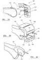
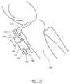
- FIGS 2A to 2Eshow perspective views of an instrument 100' corresponding to an embodiment of the invention in use with a distal end of a femur 102.
- the instrument 100'has a main body 104' including four slots 123, 124, 125, 126 which provide cutting guides for making an end cut, an anterior cut and posterior condylar cuts of the femur 102 respectively.
- the instrument 100'has seven members, e.g . 127, each having a free end and which define a plurality of attachment areas. The members are removably attached to the body by being break away members.
- a first arm 128extends from a first side of the body and a second arm 129 extends from a second side of the body.
- a portion of the inwardly facing surface of the free end of each arm 128, 129defines a further attachment area.
- Each arm 128, 129is engineered to break away adjacent the body by including a thin portion.
- a pair of pyramidal or tapered shaped members 810, 812extend away from an inner bone facing surface of the body. Each member presents a substantially flat face to the bone surface and tapers toward the body of the instrument to which they are attached in a shallow trench or recess 814 in its surface.
- the members 810, 812help to maintain the correct distal resection when the cutting block 100' is translated in the anterior direction.
- the cutting blockwill define the amount of distal resection from the contact position of the end faces of the pyramidal members with the distal femur. As the end of the femur is essentially spherical, and a point contact were used, then when translate the block is translated in an anterior direction the distal resection level would change.
- the cutting blockBy having the members in the gap between the end of the femur and the instrument body with a flat plane end face configured and positioned to pick up and engage the most distal part of each condyle, when the cutting block is translated in the anterior direction by snapping off the other attachments, the cutting block still picks up the most distal part of the femur and maintains the same distal cut. In other words only the anterior-posterior cuts are adjusted to balance the flexion gap. Having the ends surfaces of the members 810, 812 match the surface shape of the femur does not work as the end faces of the members and the condylar surfaces would clash when the cutting block is moved anteriorly. The members 810, 812 stand proud of the inner bone facing surface of the cutting block so that the distal resection can be adjusted, if needs be, by snapping the members 810, 812 off.
- each member 810, 812are provided in the form of a plurality of spaced apart parallel ribs of the same generally triangular shape and the free ends of the ribs co-operate to define a generally flat end plane for engaging the condyles.
- the instrument 100'is presented to the free end of the bone 102, as illustrated in Figure 2A and then mounted on the bone, as illustrated in Figure 2B , with the attachment surfaces defining a unique position on the patient's bone at which the instrument 102' can be attached.
- Bone pins 120, 122are then introduced via a one of the two groups of pin holes 116, 118 so as to fix the instrument to the bone and determine its initial position.
- the instrumentcan then be removed from the bone, as illustrated in Figure 2C and then the bone engagement members having the attachment surfaces 127 can be detached from the body and the side arms 128, 129 can be broken away from the body, as illustrated in Figure 2D .
- the instrument 100'can then be re-attached to the body, as illustrated in Figure 2E , but with the cutting guides 123, 124, 125, 126 at different positions relative to the initial positions by engaging the bone pins 120, 122 with different ones of the two groups of pin holes 116, 118 so as to reposition the cuts compared to the initial positioning of the instrument 100'.
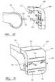
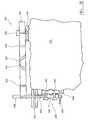
- Figure 3shows a perspective view of a further version of an instrument 100" corresponding to the first example of the invention in use with a distal end of a femur 102.
- Instrument 100"has a main body 104" bearing a first and a second slot 112", 114" which provide cutting guides for making anterior and posterior cuts.
- a pair of leg memberse.g . legs 402, 404, extend from an anterior side and a posterior side of the body 104" (although only one of the second pair of legs 406 can be seen in Figure 3 ).
- an attachment areais provided by an inward facing surface of a pad of material 408, 410, 412.
- a third cutting guide 412is provided by a slot defined by and extending over three pairs 414, 416, 418 of spaced apart plates, with the spacing between the plates defining the slot.
- the pairs of plateare attached to and supported by and between the legs 402, 404.
- a first group of nine apertures 116" and a second group of nine apertures 118"are provided in the body for receiving bone pins 120, 122 in use.
- a third group of three apertures 420 and a fourth group of three apertures 422are provided in feet portions of the legs and toward the free ends of the legs. Corresponding registered apertures are also provided in the pads of material 408, 410 located behind the feet, so that bone pins can pass through the apertures and pads and into the bone 102".
- providing the attachment mechanism at the same position as the bone attachment areashelps to reduce stresses during use of the instrument as a cutting guide.
- the instrument 100is similar to that described above and the legs are broken off, disconnected or otherwise removed from the main body 104 between initial attachment and re-attachment of the instrument to allow posterior-anterior or internal /external rotation.
- the legsare not removed and the contact pads 408, 410, 412 are deformable or removable so as to adjust the block.
- one or more of the legscan be bent away from the bone in order to adjust the position of the cutting block.
- a first subset of the first group 116" of holes and a first subset of the second group of holes 118"allow adjustment of the instruments position in the anterior-posterior direction.
- a second subset of the first group of holes 116" and a second subset of the second group of holes 118"allows adjustment of the internal-external rotation of the femur.
- new pinsare placed in the central rotating holes and the cutting guide is re-positioned using the appropriate rotating pin holes.
- the top row of holesprovides negative rotation angles for various anterior-posterior positions
- the middle rows of holesprovide pure anterior-posterior displacement
- the bottom row of holesprovide anterior-posterior displacement with positive rotation angles.
- Some of the holesallow adjustment of the position of the instrument in both directions. Hence adjustment of the instruments position in either or both directions is possible.
- the diagonal offset of the holesallow 6mm pins to have less than 6mm adjustment (e.g.
- Pairs of holesare positioned generally parallel to the slot. That is a line between a hole in the first group 116" and the corresponding hole in the second group 118" will be parallel to slot 114".
- a more complicated hole patterncan be used with holes positioned on an arc to allow rotation to be adjusted as well as the anterior-posterior position by replacing the block so the pins go through a hole on the middle row and one on the top or bottom row on the other side.
- the third group of holes 420, and fourth group of holes 422allow adjustment of the instruments position in the proximal-distal direction and varus-valgus angle of the distal cut.
- the holes in the third and fourth groupsare arranged in a generally triangular pattern so that the holes can be placed closer together in the proximal-distal direction, so that a bone pin of a certain size, e.g . 3mm diameter, can provide adjustment in smaller, e.g., 2mm, steps, by displacing the holes from side to side.
- Figure 4shows a cross-section through a second instrument 130 illustrating a second embodiment of the invention.
- Instrument 130is similar to instrument 100. However, instrument 130 includes a different adjustment mechanism by which the position of the cutting guide defined by slots 112, 114 can be adjusted.
- Instrument 130includes first 132, second 134 and third 136 crumple zones by which the shape of the instrument can be deformed.
- the crumple zones 132, 134, 136can be provided by any suitable engineering construct, such as an area made of a different material or an area with a specifically engineered weakness.
- the crumple zonecan be provided by a wafer type structure. Shims and wedges can be inserted into crumple zones that are not to be crumpled, to ensure that only the correct zones crumple when a crumple zone compressing force is exerted on the instrument.
- the surgeoncan manipulate the instrument 130 to deform its shape thereby changing the position or orientation of slots 112, 114 while the instrument 130 is still attached to the femur.
- the multiple attachment pointswhich are uniquely configured to the shape of the patient's bone, ensure that the instrument is reliably navigated to the correct position on the patient's bone and the crumple zones provide a mechanism by which the position or angle of the cut or cuts can be adjusted to allow a cut or cuts appropriate to the soft tissue balancing required to be made.
- Figure 5shows a further example 130' of the invention similar to that shown in Figure 4 .
- the crumple zones 142, 144, 146are in the form of a trench about the attachment pins and allow the whole cutting block to be moved away from or toward the bone.
- compressing the first crumple zone 146will move the cuts further into the bone, in the direction indicated by the associated arrow in Figure 5 .
- compressing the second pair of crumple zones 142, 144will move the cuts further out of the bone, in the direction indicated by the associated arrows in Figure 5 .
- the crumple zonesallow the position and angle of all the cuts to be adjusted.
- the instrumentcan include small spacers 138, 140 which can be attached to various points on the interior of the attachment areas of the instrument to provide further changes in position or angle. Small holes (not shown) or attachment points in the instrument are provided into which these spacers can be mounted using a push-fit mechanism.
- Figures 6 and 7show perspective views of a further version of an instrument 130" according to the second example of the invention and which uses crumple zones.
- the instrumentis generally similar to that shown in Figures 2A to 2E , but rather than having break away or removable parts, crumple zones are used to allow the position of the cutting guides to be adjusted.
- Two 432, 434 of the members extending from an inner, bone facing surface 436 of the body 438 of the instrumenthave generally triangular shaped voids passing through them, between the bone engaging attachment area surface and the point at which the members 432, 434 are attached to the inner surface 436.
- Removable support members in the form of triangular shaped wedges 440are located in, and are removable from, the voids, are shown in Figure 6 so that the members are correctly positioned for initial attachment of the instrument 130" to the patient's bone.
- the support membersare individually removable so that the amount and/or direction of deformation of the members can be selected by the user of the instrument, depending on which of the support members are removed.
- FIG. 7shows an instrument similar to that shown in Figure 6 , in which the wedges have been removed and in which a further two of the members 442, 444 have been provided with voids defining crumple zones by which the members can be deformed. Crumpling members 432, 434, 442 and 444 will give a change in the proximal-distal direction. The provision of crumple zones in a perpendicular direction can be used to adjust the anterior-posterior position.
- the instrumentcan be adjusted similarly to the method described above and with the deformable members deforming out of the way.
- the instrumentcan be adjusted prior to pinning the instrument to the bone. The method would then be to place the instrument on the bone in its initial position, remove the wedges, adjust the position of the instrument as required by deforming the members, pin the cutting block in the adjusted position and then make the adjusted cut.
- deformable membersare also used under the anterior flange of the instrument.
- FIG 8shows a further version of an instrument 130"' according to the second example of the invention which includes crumple zones.
- the instrumentis generally similar to instrument 100" shown in Figure 3 .
- each foot 450, 452includes a single aperture 454, 456 by which the instrument can be pinned to the bone 102 in use.
- a portion of the foot above the aperturehas a plurality of triangular apertures passing therethrough, providing a crumple zone 458, 460 by which the position of the instrument in the inferior-superior direction can be adjusted.
- an aperture 462, 464is provided for receiving a threaded fastener (not shown) which is received in a treaded aperture below the crumple zone so that by operating the threaded fastener the top and bottom parts of the crumple zone are urged together so as to crush the supporting structure and hold the crumple zone in a preferred degree of deformation.
- a threaded fastenernot shown
- the crumple zone materialis resilient and so the threaded fastener can be operated to crush or release the crumple zone with the instrument changing its position accordingly.
- FIG. 9shows a removable support part which can be used with various of the second examples.
- the support part 470has a body 472 with a plurality of wedges 474, 476, 478, three in the illustrated example, extending form a side thereof and sized and shaped to be receivable in the triangular apertures of the crumple zones 458, 460.
- the wedgescan be pushed into the apertures in the crumple zones to prevent them collapsing when the instrument 130"' is being initially mounted on the bone and then removed when it is desired to change the position of the instrument by deforming the crumple zones.
- the wedgescan also be used when the crumple zones have been partially collapsed, by forcing them into the apertures so that the apertures in the crumple zones are at least partially reformed and the instrument caused to change its position at least partially back to its initial position.
- FIG 5Ashows a further crumple zone mechanism 480 that can be used in various examples of the invention, such as instrument 130' shown in Figure 5 .
- the crumple zone mechanism 480can be used to replace the crumple zone shown in Figure 5 .
- a part of the instrument 482 including the attachment area 484has a chamber 486 including material which can be deformed.
- a foot part 488 of another part of the instrumentis slidingly received in the chamber with portions of deformable material above 490 and below 492 the foot part.
- the position of the instrumentcan be adjusted toward the bone by compressing and deforming the lower portion of material 492 or the position of the instrument can be adjusted away from the bone by compressing and deforming the upper portion of material 490.
- Figures 10 and 11show schematic cross-sections through a third example 150 of the invention in the coronal and sagittal plane, respectively.
- the third example of the instrument 150includes a main body section 152 which bears first 154, second 156 and third 158 slots which provide three cutting guides for receiving a cutting instrument, such as a saw, in use. In other examples, further cutting guides can also be provided, e.g . 155 & 157.
- Instrument 150includes a first member 160 having a first attachment area 164 having a surface shape matching the shape of the surface of a corresponding region of the patient's bone.
- a second member 162also has an attachment area 166 having a surface shape matching the shape of a corresponding area of the surface of the patient's bone 168.
- FIG. 10the bone 160 is a distal femur showing in the lateral plane.
- the same principlescan also be applied to the tibia.
- the first attachment member 160includes a first screw mechanism 170.
- the second attachment member 162includes a second screw mechanism 172. Screw mechanisms 172 or 170 can be operated to translate the cutting guide 158 relative to the bone 168 in a proximal-distal direction, as illustrated by the double headed arrows shown in Figure 11 .
- the instrument 150includes a further adjustment mechanism 174, in the form of a long hole, by which the screw mechanism 170 can be moved with respect to the body 152 in an anterior-posterior direction as illustrated by the associated double headed arrow in Figure 11 .
- a second, similar adjustment mechanism(not shown) is provided for the second screw mechanism 172.
- the adjustment mechanisms 174are operable to translate the main body 152 in an anterior-posterior direction so as to move the position of the cutting guide anteriorly or posteriorly relative to bone 168.
- the screwsthemselves can be of captive-pane type or similar with a threaded bushing inside the block, in order to prevent interference of the top or the end of the screws with the body tissues. Varus-valgus variation of the cutting plane can also be achieved by alternative settings of screws 170 and 172.
- the position of the cutting guides 154, 156, 158can be adjusted by using the screw mechanisms to move body 152 to allow the positions of the anterior, posterior and distal cuts to be adjusted.
- Attachmentis also provided by pins that pass through the attachment members 162, 160 and the surface matching areas, on the anterior side of the bone, in positions that are central to the anterior face.
- the screw mechanismsprovide the adjustment mechanism.
- Colours or other indicia or markingscan be provided on the screws to allow the position to be altered or adjusted by predetermined amounts.
- the amounts to be usedcan be specified in a look up table or from a computer program that have been derived from soft-tissue balancing measurements.
- FIG 12shows a further version of an instrument 150' according to the third example of the invention.
- Some of the features of the instrument 150'are similar to those of the instruments shown in Figures 3 and 8 and so are not described again in detail.
- the mechanism for adjusting the position of the instrumentdiffers.
- a patient specific foot 500, 502is provided at each end of the instrument body and includes a surface providing an attachment area 504.
- Each patient specific footis attached to the main body 506 by an adjustment mechanism which allows movement of the body 506 relative to each foot independently in the anterior-posterior direction 508 and/or in the inferior-superior or proximal-distal direction 510.
- Each adjustment mechanismuses a captured screw 512, 514 which passes through a threaded plate 516, 518 which can slide in a plate receiving formation in the anterior-posterior direction 508.
- a capture plate 520is provided in each block to hold the block 500, 502 at a fixed position with respect to the end of its screw.
- a feature on the underside of the bodyinteracts with a mating feature on the block to prevent rotation of the block 500, 502 relative to the body 506.
- the screws 512, 514can be rotated to cause the body 506 to move in the proximal-distal direction relative to the bone an so adjust the position of the cutting guides after the instrument 150' has been mounted on the bone 102.
- Figure 13shows a schematic cross-section through a fourth example 180 of the instrument.
- the fourth exampleis similar to the first and second examples.
- the adjustment mechanismis provided in the form of individual spacers 182, 184, 186 that can be selectively attached to the attachment areas so as to adjust the position of the cutting guide, defined by slots 112 and 114, relative to the bone 102.
- the individual piecescan be attached using a push-fit or snap-fit mechanism and can be made of a plastics material.
- the spacerscan be colour coded to indicate what change in the position of the cutting guide will result when using the particular spacer.
- the spacerscan be made to fit behind the surface matching areas or on top of them or can replace the surface matching areas patch completely in different examples.
- Figure 14Ashows a perspective view of a part of a further version of an instrument 180' according to the fourth example of the invention which uses patient specific spacers.
- the instrument 180'is generally similar to those shown in Figures 3 , 8 and 12 .
- Figure 14Bshows a patient specific component 530 a bone facing surface of which 532 is shaped to match the shape of the patient's bone and provides an attachment area.
- An upper surface of the componenthas a generally tray like form and ends of the tray are sized and configured to provide a push fit attachment to the foot of the instrument 420 as best illustrated in Figure 14A .
- An aperture 534is provided in the body of the tray and in registration an aperture 536 in the foot of the instrument for receiving a bone pin passing through the foot so as to attach the instrument to the bone 102.
- Figure 14Cshows a further push fit component 540 which also has a bone facing surface of which 542 is shaped to match the shape of the patient's bone and provided an attachment area.
- This component 540has two apertures 544, 546 so that the component can be attached to the foot 420 at two different discrete positions while allowing a bone pin to pass through the foot and component. Hence, this component allows movement of the instrument in the proximal-distal direction.
- Figure 14Dshows a further push fit component 550 which also has a bone facing surface of which 552 is shaped to match the shape of the patient's bone and provided an attachment area.
- This component 550has a single extended aperture 554 which is shaped with a plurality of waists so that the component can be attached to the foot 420 at three different discrete positions while allowing a bone pin to pass through the foot and component.
- this componentallows discrete linear movement of the instrument in the proximal-distal direction but at a fixed angle
- Figure 14Eshows a spacer component 560 also having a generally tray like shape and sized and configured to form a stacked arrangement with the patient shape specific components illustrated in Figures 14B to 14D .
- An extended aperture 562is provided in the body of the tray to allow a bone pin to pass through the stacked arrangement in use. This spacer allows for angular and linear displacement of the instrument.
- Figure 14Fshows a spacer component 570 also having a generally tray like shape and sized and configured to form a stacked arrangement with the patient shape specific components illustrated in Figures 14B to 14D .
- An extended aperture 572 having two waistsis provided in the body of the tray to allow a bone pin to pass through the stacked arrangement in use in three discrete positions. This spacer allows only linear displacement of the instrument.
- Figure 14Gshows a stacked arrangement 580 of a spacer, e.g . spacer 560, and a patient specific shaped component, e.g . component 550.
- the spaceris dimensioned and configured to provide a push fit attachment of the arrangement via the spacer to the foot 420.
- the patient specific shaped componentis then push fit attached to the spacer.
- the initial position of the instrumentis planned with at least one spacer on each side of the bone.
- the position of the instrumentcan be adjusted by using different thickness spacers to move the instrument in the anterior-posterior direction.
- spacerscan be moved from one side of the bone to the other which also adjusts the position of the instrument in the anterior-posterior direction.
- the spacershave a constant thickness. However, it is also possible to vary the angular position of the instrument by using spacers which have a varying or tapering thickness.
- FIG. 15shows a schematic cross-section through a fifth example 190 of the instrument.
- the fifth exampleis similar to the first, second and third examples.
- the adjustment mechanismis provided by three screws 190, 194, 196 each received in a threaded hole.
- the foot of each screwbears a member whose outward surface provides an attachment area whose shape substantially matches the shape of the surface of a corresponding region of the patient's bone 102.
- the patient specific attachment areas on the feet of the screws 198, 200, 202allow the instrument to be attached only to a single unique position on the patient's bone, while operating the screws 192, 194, 196 allows the cutting guide, provided by slots 112, 114, to be moved relative to the bone 102.
- Channelsare provided in the main body of the attachment 190 so that the contact feet can slide in the channels and maintain the correct foot orientation, with respect to the local bone surface and the body of the instrument.
- the angle and position of the screws and channelare optimised to maximise the area of contact to the patient specific part for the expected range of soft tissue dependent angle and position changes.
- Attachment pinscan be placed through a surface matching attachment area to improve the stability of attachment.
- Figure 16shows a schematic cross sectional side view of a sixth example 210 of a surgical instrument according to the invention intended for use with the distal end of a femur 211.
- Figure 17shows a perspective view from an underside of the sixth example 210.
- the instrument 210includes a main body 212.
- Body 212bears a first slot 214, a second slot 216, a third slot 218, a fourth slot 220 and a fifth slot 221.
- First slot 214provides a cutting guide for accepting a saw blade for making an anterior femoral cut.
- Second and third slots 216, 218respectively provide cutting guides for receiving a saw to make first and second femoral chamfer cuts.
- Fourth slot 220provides a further cutting guide allowing a femoral posterior cut to be made.
- Fifth slot 221provides a further cutting guide allowing a femoral distal cut to be made.
- Body 212includes two threaded hole each of which can receive a threaded member 222 therein. Other threaded holes in parallel planes behind member 222 can also be provided.
- a first end of the body 212includes a first curved end plate 224 having first and second threaded holes 226, 228 therein toward a free end.
- a second curved plate 230is provided at a second end of the body 212 and includes a first set of offset threaded holes 232 and a second set of threaded offset holes toward a free end thereof. Each of the holes receives a threaded member (not shown) similar to threaded member 222.
- six threaded membersare provided and the free ends thereof provide six attachment areas by which the instrument 210 can be attached to the distal end of the femur, or other body in other examples.
- the ends of at least one of screws 222, 236are shaped to match the shape of the surface of the bone.
- the end bone contact areasare keyed with respect to the instrument so they do not rotate when the screws on which they are mounted are rotated.
- Screw members that are not tipped with surfaces that match the bone surfaceare tipped with a point, the position of which is known with respect to the surface described by the medical images.
- the number of screws usedis six, but fewer screws can be used if fewer dimensions are to be changed. For purely positional adjustments this can be reduce to two, e.g ., to allow anterior-posterior and proximal-distal changes. In cases where the angles of the cuts are changed there will be a small amount of shear force on screws with surface matching areas. For small angular changes ( ⁇ 3°) that are allowed for, this will not affect the surface match and will be absorbed in the mechanism part-to-part interfaces.
- Second end plate 230includes a slot 238 toward a lower end thereof providing a further cutting guide. There is a corresponding slot in the body part 212. Second end plate 230 is attached by a pivot mechanism (not shown) to the main body 212. A pair of threaded members (of which only member 242 can be seen) can be operated to pivot end plate 230 thereby altering the angle of slot 238 relative to body 212.
- slot 238provides a cutting guide by which a femoral distal cut can be made using a saw when instrument 210 is attached to a femur in use.
- the threaded memberscan be adjusted to change the position of the cutting guides 214, 216, 218, 220, 221 relative to the distal end of a femur so that the position of the femoral cuts can be adjusted as required to provide soft tissue balancing.
- the amounts of adjustmentcan be marked on the screws and guides and can be determined manually from a look up table or from a computer controlled tissue balancing measurement.
- Figure 18shows a part of the instrument 600 which includes three slots, 602, 604, 606, providing cutting guides for making the same cut.
- a single or multiple (as illustrated) push fit inserts 608, 610are used to block the slots that are normally not used so that only a single slot is initially available for making the cut.
- the position of the slot to be used for making the cutcan then be adjusted by removing the inserts from another of the slots so that that slot can then be used for making the cut in a preferred position.
- the insertscan be colour coded to easily identify the direction of the slot displacement.
- the points/features/surfaces on the bonesare selected such that they are outside the surfaces being removed.
- the instrumentis then uniquely re-locatable even after the initial cuts are made. This is particularly useful for a surgeon who uses a measured resection approach and who wants to make all his cuts and check afterwards. This allows him to remount his cutting guides and make any adjustments he sees as necessary.
- the inventioncan be adapted for resection of any bone or hard-body material and flat-cut implant type.
- any bone or hard-body material and flat-cut implant typeFor example, for the tibia the complexity can be reduced due to a single cut being used.
- the inventioncan also be applicable to preparing round surfaces for any type of implant, in which case a burr can be used to remove the material.
- Figure 19shows a schematic side view in the sagittal plane of a further example 300 of the invention providing an adjustable tibia cutting instrument.
- the instrument 306includes a main body section 308 with a cutting slot 322 through which a saw blade can be guided to make a tibial cut.
- Instrument 306is attached to the surface of the tibia bone 310 by an attachment part 312 having a surface shape matching the shape of the surface of a corresponding region 314 of the patient's tibia 310.
- a screw mechanism 316can be operated to adjust the position of the cutting slot 322 in the proximal-distal direction.
- a second screw mechanism 318is also provided which can be operated to change the slope of the cut by allowing the guide to pivot in the varus-valgus direction about it.
- FIG 20shows a further variation of an instrument according to the invention similar to the instruments shown in Figures 16 , 17 and 19 .
- the instrument 620has a plurality of slots 622, 624, 626, 628, 630 providing cutting guides.
- a main body 632 of the instrumentis mounted on the bone 640 by an attachment area component 642 which has a surface form matching the patient's bone shape.
- the component 642is attached to the body 632 by an adjustment screw 660 so that the instrument can be stabilised during cutting and after the position of the instrument has been adjusted.
- the surfaces of the bone and attachment areawill not match exactly after angular or linear adjustment.
- the bone surfaceis typically cut away for distal or proximal cuts so adjustment for stabilisation is not always necessary after the block instruments position has been adjusted.
- the other patient specific attachment area 644is attached to a further part 646 of the instrument by a pivot mechanism 648 to allow some rotation of the instrument relative to the bone 640.
- the pivot mechanismincludes two screws. Threaded bores are provided in foot component 644 into which free ends 652, 654 of the screws engage. Apertures are provided in part 646 to receive the screw shanks but are a loose fit to allow some pivoting movement.
- the end of foot component 644provides an end stop to prevent over rotation of the body.
- a bone pin 650 passing through an aperture in the foot component 644prevents the foot component 644 moving relative to the bone.
- the instrumentsimply translates. However, if only one screw is operated, or the two screws are operated in opposition senses, then the main body of the instrument will pivot or tilt thereby providing some angular adjustment of the position of the instrument.
- the pivot mechanismallows screw driven rotation of plus or minus approximately 2°.
- a single screw and a flexible hingecan be used to provide the pivot mechanism. Measured rotations in between 2° steps can be achieved by measure turns of the screws.
- Part 646is itself mounted on a screw thread 656 so that the remainder of the main body 632 can be moved toward and away from the bone by operating thread 656 using head 658 and operating adjustment screw 660.
- Figures 21 A and 21 Bshow perspective views of a further instrument 680 being an example of the invention similar to those shown in Figures 16 , 17 , 19 and 20 .
- Figure 21 Bshows a perspective view from a bone engaging side of the instrument 680 and
- Figure 21Ashows the instrument mounted on a femur 102 in use.
- the instrument 680has a first bone engaging portion 682 and a second portion 684 which includes a plurality of slots defining cutting guides for making a plurality of cuts typically used when preparing a femur to receive an implant.
- the first and second portions between themcomprise the body of the instrument.
- the bone engaging portionhas a bone facing side which includes a surface 670 extending over the bone facing side and which provides an extended bone attachment area whose shape matches the patient specific shape of the surface of a corresponding part of the surface of the patient's bone.
- the bone engaging portionis the only part of the instrument that engages the bone and ensures that the instrument is mounted on the bone at a unique pre-selected position.
- the cutting guide bearing portion 684 of the instrumenthas first 672 and second 674 portions 672 each bearing at least one slot.
- Portion 672has a slot 676 for guiding the making of a distal cut.
- Portion 672is attached to the bone engaging portion 682 by a pair of threaded screws 684, 686 which are captured so that operation of the screws causes the first and second portions to translate in the distal-proximal direction relative to the bone 102 thereby allowing the position of the distal cut to be adjusted.
- the second portionincludes five slots 690 which can be used to guide the making of anterior and posterior cuts and angled cuts typically used when preparing a femur during knee arthroplasty procedures.
- Portion 674is attached to the first portion 672 by a further pair of threaded screws 688, 690 which are captured so that operation of the screws causes the first and second portions to translate in the anterior posterior direction relative to the bone 102 thereby allowing the position of various of the cuts to be adjusted.
- FIGS 22A, 22B and 22Cshow perspective views of part of a further example of an instrument 700 according to the invention.
- the instrument 700is generally similar to that shown in Figures 3 , 8 and 12 .
- the instrumenthas a different type of adjustment mechanism.
- the adjustment mechanisminvolves the use of inserts or attachments with slots in defining the cutting guides.
- the slots in different inserts and attachmentsare off set by different amounts and so allow the position of the cutting guide to be adjusted relative to the bone to which the instrument is attached.
- Figure 22Ashows a perspective top view of the main body part 701 of an instrument 700 and includes a large rectangular recess 702 in the main body and having an aperture 704 passing through the body and providing access to the bone beneath the instrument in use.
- the recessincludes a shoulder 706 extending around a part of the recess and which acts to control the depth of insertion of an insert 710 as illustrated in Figure 22B .
- the insertis a metal block which includes a slot 712 passing through the block.
- the recess and insertare dimensioned and shaped so that the block mates with the recess in a push-fit manner to securely attach the insert to the main body of the instrument.
- the insertacts as a shim to control the position of the slot and hence cutting guide.
- a set of insertsare provided having different amounts of offset of the slot and also having slots at different angles so that a particular insert can be selected and used so as to adjust the position and/or direction of the cut as defined by the selected insert.
- a plurality of inserts or attachmentscan be provided as part of the instrument 700.
- a cutting guide insert or attachment 714can be provided that co-operates with formations adjacent feet 716 and 718 to allow the insert 714 to be push-fit attached to a side of the instrument 700.
- Insert 714includes a slot 715 providing a cutting guide which can be used when making a distal femoral cut. A particular insert with a selected off set slot position or slot angle is selected and inserted in the instrument body in order to adjust the position of the cut to be made.
- the inserts or shims 710, 714are generally made available with different lateral and angular offsets to permit adjustment of the cut surface after the soft-tissue measurement or other appropriate adjustments are made based on intra-operative or pre-operative information.
- the recess 702is wide enough to allow for the expected variation in the cutting surfaces.
- the shimsare inserted into the main body after any adjustment calculations have been made.
- the shimsare re-usable and their simple form allows for easy sterilization and use across a range of sizes and cutting positions in the patient specific main body 701.
- One end of the recess 706can be left open to allow for inserts longer than the slot, e.g . for patients with small bones, to be used.
- Figures 22D, 22E and 22Fshow examples of different insert blocks by way of further explanation of how they can be used to adjust the cutting instrument.
- Fig. 22Dshows a an insert block 720 having a slot aperture 722 extending along and parallel to the longitudinal axis of the block. By using this block instead of block 712, the position of the resulting cut can be adjusted in the anterior-posterior direction.
- Insert block 724 shown in Figure 22Ehas a slot aperture 726 again extending along and parallel to the longitudinal axis of the block 724, but the slot is closer to a side of the block 724 compared to block 720.
- Fig. 22Fshows a an insert block 728 having a slot aperture 730 extending generally along the longitudinal axis of the block, but not parallel to the longitudinal axis of the block.
- block 728can be inserted into the instrument and used in order to adjust the angular position of the resulting cut.
- the first set of blocksis used for making the anterior, posterior, distal and proximal cuts. These cuts can vary in their rotation (Varus-Valgus) and lateral positioning. In typical use, the implant can be moved laterally up to +/-3mm in steps of 1.5mm. To provide this degree of cut adjustment three blocks are used, a first with neutral positioning of the slot, a second with a 1.5mm offset of the slot and a third with a 3mm offset of the slot. It can also be helpful to provide blocks with various amounts of variation of the varus-valgus angle, for example 0, 1, 3 or 5 degrees. Hence, by also providing insert blocks with slots which yaw and pitch it is possible to cover all values of Varus-Valgus and lateral movement with, e.g ., twelve blocks.
- the second set of blocksis used for making the chamfer cuts.
- a similar recess for receiving the insert blocksis used for the chamfer cuts and, for both of the chamfer cuts, the recess is aligned with the chamfer angle.
- the insert blocks in the second setare slightly longer than the blocks of the first set and do not go as deep into the body of the instrument. They can be held in a stable position, since the recesses for receiving the insert blocks for the chamfer cuts and the anterior, posterior and distal cuts will overlap in the femur. Again twelve blocks can be used to cover all of the displacement combinations (for chamfers at 45°) and for other angles of chamfers twenty four blocks can be used.
- Figure 23shows a schematic cross section through an example of a further adjustment mechanism 750 that can be used in the instrument of the invention.
- a first part 752 of the adjustment mechanismis a part of the main body of the instrument and a second part 754 of the adjustment mechanism bears a member or foot including an attachment area (not shown) of the instrument.
- Part 752defines a hollow portion 756 into which part 754 can slidingly engage in a direction as illustrated by double headed arrow 758.
- a threaded shaft 760has a head 762 at a free end and passes through a first pair of wedge shaped members 764, 766 which are stationary and a second set of wedge shaped members 770 which are movable and can be driven back and forth in a direction illustrated by double headed arrow 772 by rotating thread 760.
- wedges 764, 766are stationary, when driven toward them by rotation of thread 760 of the drive mechanism, the slanted end faces of wedges 768, 770 will ride onto and slide up the slanted faces of the wedges 764, 766 and the second part 754 will be driven out of and away from hollow portion 756, thereby increasing the separation between the main body and the attachment areas and so adjusting the position of the cutting guides borne by the main body.
- the joint volume itselfdoes not have to contain any adjustment screws and the overall instrument can be made more compact.
- Screw 760moves the moveable members 768, 770 in the anterior-posterior direction to cause up/down movement of wedges 764, 766 and hence the attachment areas are also caused to move up and down.
- No toolis required for adjustment in the proximal distal direction and this mechanism provides more compact control particularly useful in minimally invasive surgery (MIS) procedures.
- MISminimally invasive surgery
- Figures 24A and 24Bshow perspective views of a further example of an instrument according to the invention.
- Figure 24Ashows a perspective view from a rear side of the instrument 780
- Figure 24Bshows a perspective view from a front side of the instrument 780 mounted on a tibia 782 in use.
- the body 784 of the instrumentincludes a slot 786 passing through the body and providing a cutting guide for receiving a cutting device for making a tibial cut in use.
- Two groups 788, 790 of three aperturespass through the body for receiving bone pins 792, 794 for securing the instrument to the tibia in use 782.
- a pair of arms 796, 798extend from the main body and bear a first patient specific shaped member 800 and a second patient specific shaped member 802 on a bone facing underside of the arms, each member 800, 802 providing an attachment surface configured to engage with the patient's bone as best seen in Figure 24B .
- a bone facing side of the main bodybears a third patient specific shaped member 804 providing a further attachment surface 806 for configured to match the shape of an area on the anterior surface of the tibia 782 in use.
- the instrumentis used similarly to similar examples described above. Initially the instrument is mounted on the tibia by engaging the attachment areas with the bone surface so as to initially locate the instrument at a predetermine position. Bone pins 792, 794 are then introduced via holes 788, 790 to secure the instrument to the tibia. If adjustment of the position of the cut defined by the slot 786 is required for any reason, then the instrument 780 is removed from the bone pins and the members 800, 802, 804 removed from the instrument and then the instrument can be replaced on the tibia on the bone pins using different ones of the holes 788, 790 so as to move the slot upward or downward in the proximal-distal direction so as to adjust the height of the tibial cut.
- a patient-specific instrumentis manufactured, for example, using a rapid prototyping technique, so that the attachment areas of the instrument are patient-specific and allow the instrument to be uniquely attached to the patient's bone.
- Thiscan be achieved using various types of data describing the geometry or shape of the patient's bone, for example, derived from CT scan data.
- the invention and the first, second, fourth and fifth examplesuse unique negative shapes which allow them to be fitted to the patient-specific bone surface. These shapes can cover the complete bone surface or selected parts thereof where the geometry is accessible.
- the second approachis more appropriate where soft tissue is attached to the bone (e.g . cartilage) which cannot accurately be modelled in a pre-operative planning step.
- the most important changes to cuts in order to accommodate soft tissue balancingare being able to increase or decrease the tibial slope, being able to move the tibial cut in a more distal or proximal direction and being able to adjust the varus-valgus angle.
- the most important changes to cuts in order to accommodate the soft tissue balancingare being able to move the femoral cut in the anterior or posterior direction. It is also important to be able to move the distal femoral cut in a more proximal direction. It is also useful to be able to change the varus-valgus angle on the femur. It is also beneficial to be able to change the internal/external rotation.
- the tibial cutis made according to the planned surgical procedure. Then, a determination is made of potential changes in order to improve the flexion and extension gap, either using a tool or by visual inspection and experience of the surgeon. The instrument is then attached and adjusted as required so that the resulting cut will provide the required flexion and extension gaps.
- the tibial and femoral cutsare made according to the planned procedure. Trial implants are applied and then spacers, can be used to assess the flexion and extension gap. Then, the instrument can be applied to the cut tibia and femur and adjusted to allow further corrective cuts to be made as required, in order to provide the desired flexion and extension gap.
- this approachwill miss the corrections available for the femur by simply moving the distal femoral cut in a more proximal direction.
- standard spacer elementsthat match the cut surface
Landscapes
- Health & Medical Sciences (AREA)
- Surgery (AREA)
- Life Sciences & Earth Sciences (AREA)
- Biomedical Technology (AREA)
- Public Health (AREA)
- Oral & Maxillofacial Surgery (AREA)
- Nuclear Medicine, Radiotherapy & Molecular Imaging (AREA)
- Veterinary Medicine (AREA)
- Dentistry (AREA)
- Engineering & Computer Science (AREA)
- Orthopedic Medicine & Surgery (AREA)
- Heart & Thoracic Surgery (AREA)
- Medical Informatics (AREA)
- Molecular Biology (AREA)
- Animal Behavior & Ethology (AREA)
- General Health & Medical Sciences (AREA)
- Physical Education & Sports Medicine (AREA)
- Transplantation (AREA)
- Surgical Instruments (AREA)
- Prostheses (AREA)
- Agricultural Chemicals And Associated Chemicals (AREA)
Abstract
Description
- The present invention relates to surgical instruments, and in particular to a cutting guide which can be used in orthopaedic arthroplasty procedures to allow soft tissue balancing.
- Orthopaedic arthroplasty procedures often involve the use of an implant or implants which is used to replace an articulating surface or surfaces of the joint. Usually such implants are attached to a resected or otherwise prepared part of a patient's bone. A cutting guide can be attached to the patient's bone to allow surfaces of the bone to be resected to accept the implant. A variety of approaches are available to planning, guiding and placing the cutting guides, implants and other instruments used during the procedure, so as to try and ensure that the joint is correctly rebuilt. However, for some joints, such as the knee joint, it is also necessary to take into account the soft tissue structures of the joint, such as the ligaments, so as to try and ensure that the joint is correctly rebuilt.
- Computer Assisted Surgery (CAS) systems can be used to plan and navigate the position of cutting guides, implants, etc in order to try and take into account soft tissue structures. The planned position of a cutting guide can be updated intra-operatively based on measurements of the soft tissues in order to adjust the cuts to be made to the bone to change the eventual position of the implant. However, CAS systems are expensive and are not widely available. Further some surgeons prefer not to use CAS systems and prefer to use their own workflow and techniques.
- A non-navigated approach to positioning a cutting guide can be achieved by producing a patient specific cutting guide using data from captured images of a patient's bone (sometimes referred to as "templating") so that the cutting guide can be attached in a predefined position to the patient's bone thereby fixing the position of the cuts in the planned position. However, this approach is not suitable for allowing soft tissues to be taken into account as the position of the cuts relative to the patient's bone is fixed pre-operatively. The actual cuts that may be required in order to take into account the soft tissue structures of the joint or for other reasons may only become apparent intra-operatively and so the cuts defined by the cutting guide are non-optimal.
EP-1,669,033 discloses an adjustable cutting guide for positioning cutting guides relative to the distal part of the femur. The cutting guide has a number of slots and an arm extending from the body of the guide to contact the diaphysis which provides a mechanical constraint to ensure that the guide is positioned in a specific manner with respect to the bone. The medial-lateral positioning can also be limited using fixed mechanical constraints, to centre the guide with respect to the intra-condylar notch. A plurality of screws is provided so as to allow adjustment of the position of the cutting guide, for example in the flexion / extension angle and the axis of rotation. The anterior / posterior position of the guide is largely limited by the contact point at the end of the extended arm.WO 98/32384 US 2005/234461 describes tools designed to be customisable to increase the speed, accuracy and simplicity of performing total or partial arthoplasty. A method for designing an instrument is described in which the shape of the instrument is derived from CT slices. Information is used to define the preferred location and orientation of saw guides or drill holes of surgical instruments. A patient specific first component is described with a plurality of apertures for receiving cutting instruments. A second portion including a number of apertures for receiving a cutting instrument overlays the first component which sits on a patient's bone. A spacer can be placed between the parts so as to adjust the height of the femoral cut through slots. Alternative designs can be used to control the movement and rotation of cutting blocks. For example, a number of pegs can be used to allow rotational adjustment. Alternatively, a dome sitting within a concave portion can be used to allow greater rotational movement while limiting lateral movement.US-5,688,279 describes a femoral alignment guide including a body and a 6° femoral cutting block. The instrument is mounted on an intramedullary rod and includes an intercondylar saddle by which the instrument seats in the intercondylar notch. Once positioned, the position of the cutting block can be fine tuned by rotating a wing-nut and moving a calibrated stop component. This allows the cutting block to be slid proximally or distally.- The present invention provides a mechanism allowing intra-operatively available soft tissue information, or other information, to be used to make the correct cuts, without requiring a complex planning or navigation system.
- According to a first aspect of the present invention, there is provided a surgical instrument for use in an orthopaedic arthroplasty procedure to be carried out on a knee joint of a patient and allowing soft tissue balancing for the knee joint, comprising: a body having a plurality of members each removably attached to the body as break away parts and each having a free end which define a plurality of attachment areas, the plurality of attachment areas being configured using data specific to a distal part of a femur of the joint of the patient so as to attach to the distal part of the femur in a unique position at least a first cutting guide; and an adjustment mechanism operable to change the position of the cutting guide relative to the distal part of the femur by removing the plurality of members from the body to allow the instrument to be moved relative to the distal part of the femur to change the position or angle of the cutting guide, the adjustment mechanism including a plurality of holes in the body for accepting fixings.
- Hence, the patient specific attachment areas automatically navigate the device so that it is attached to the bone in a predetermined position. However, the cuts to be made to the bone can then be adjusted so as to help provide at least some soft tissue balancing. Hence, no complex navigation system is needed and the ability to tailor the bone cuts to compensate for soft tissues of the joint is provided.
- The adjustment mechanism can allow translation and/or rotation of the or each cutting guide.
- The instrument can include a plurality of different cutting guides. The plurality of different cutting guides can be borne by the body.
- The or each cutting guide can be adapted to receive a cutting device or part thereof in use. The cutting device, or part thereof, can be a saw blade, or a milling device.
- The or each cutting guide can be adapted and/or positioned and/or located and/or angled to allow a femoral cut to be made to the bone guided by the cutting guide.
- Each group of a plurality of apertures can comprise a plurality of sub-groups of a plurality of apertures allowing adjustment in different directions and/or angle.
- The plurality of attachment areas can engage the bone on at least five different positions of the surface of the bone. Preferably at least three different attachment areas are provided, more preferably at least four different attachment areas and most preferably five, or at least five, different attachment areas are provided. At least seven or seven attachment areas can also be used. At least one of the attachment areas can contact the side of the bone and at least one of the attachment areas can contact the end of the bone.
- According to a further aspect of the invention, there is provided a method of manufacturing a surgical instrument, comprising: capturing data specifying the shape of a distal part of a femur of a knee joint of a patient from the patient; and manufacturing at least the attachment areas of the surgical instrument according to the first aspect of the invention using the captured data. Preferably, the data is captured using an imaging technique, for example, a CT scan.
- Embodiments of the invention will now be described, by way of example only, and with reference to the accompanying drawings, in which:
Figure 1 shows a schematic cross sectional view through a first example of a surgical instrument;Figures 2A to 2E show perspective views of an embodiment of an instrument according to the invention;Figure 3 shows a perspective view of a further example of an instrument;Figure 4 shows a schematic cross sectional view through a second example of a surgical instrument;Figure 5 shows a schematic cross sectional view through a further version of the second example shown inFigure 4 ;Figure 5A shows a schematic cross section through an adjustment mechanism part of an example instrument;Figure 6 shows a perspective view of a further example of an instrument;Figure 7 shows a perspective view of a further example of an instrument similar to that shown inFigure 6 ;Figure 8 shows a perspective view of a further example of an instrument;Figure 9 shows a schematic side view of a removable support member which can be used with the instrument shown inFigure 8 ;Figures 10 and 11 show schematic cross sectional views through a third example of a surgical instrument;Figure 12 shows a perspective view of a further example of an instrument;Figure 13 shows a schematic cross sectional view through a fourth example of a surgical instrument;Figures 14A to 14G show perspective views of a part of further example of an instrument and spacers components for use with the instrument;Figure 15 shows a schematic cross sectional view through a fifth example of a surgical instrument;Figures 16 and17 show perspective views of a sixth example of a surgical instrument;Figure 18 shows a view of an adjustment mechanism which can be used in an example instrument;Figure 19 shows a schematic cross sectional view through a seventh example of a surgical instrument;Figure 20 shows a schematic cross sectional view of a further example of an instrument;Figures 21 A and 21 B show perspective views of a further example of an instrument;Figures 22A to 22F show perspective views of a further example of an instrument and insert blocks used as part of the adjustment mechanism of the instrument;Figure 23 shows a schematic cross sectional view of a further adjustment mechanism which can be used in an example instrument; andFigures 24A and 24B show perspective views of a further example of an instrument.- Similar items in different Figures share common reference numerals unless indicated otherwise.
Figure 1 shows a schematic cross-sectional view through a first example of asurgical instrument 100, mounted on the proximal tibia ordistal femur 102. InFigure 1 , the cross-section is shown in the coronal plane. Theinstrument 100 has amain body part 104 and a number ofattachment areas distal femur 102. Alignedslots body 104 and provide a first cutting guide for accepting a saw blade in use to resect thebone 102. Other slots are also provided in the body for making other cuts to the femur or tibia, as required when preparing the bone for an implant, but are not shown inFigure 1 , for the sake of clarity. Theinstrument 100 also includes a first group of fourholes 116 and a second group of fourholes 118 which in use can acceptbone pins Figure 1 .- Pre-operatively, data defining the geometry of the proximal part of the patient's tibia, or distal femur, is collected, for example by carrying out a CT scan. That data is then used in the manufacture of the
instrument 100, for example using rapid prototyping techniques, so that the attachment areas of the instrument are adapted to match the surface of the proximal part of the tibia, or distal part of the femur, in a unique way. - Hence, for example, the instrument can be attached to the patient's tibia in only a single unique position. Therefore, in use, the instrument is automatically navigated to the correct position on the patient's tibia, as there is no other position in which the instrument can be reliably attached to the patient's tibia. Once attached,
slots - The gap between the bone surface and the parts of the instrument which are not in contact with the patient's bone, are planned to provide sufficiently clearance from the bone surface to allow +/-3mm of anterior-posterior or proximal-distal movement and +/-3° of varus-valgus and flexion-extension and interior-exterior rotation. This planning of the shape of the instrument can be achieved by using a grid search of the allowable range of angles and positions in steps of 1mm & 1° or divisions thereof. Giving in this example 5*5*5*5*5 corresponding to 3124 grid points. For each grid point, constructive solid geometry of operation of the CT scan of the bone against the potential inner instrument surface is carried out. From this, an inner surface of the instrument can be designed and manufactured that will clear any bone, for any desired offset. The unique attachment areas are then placed where they should be for a zero off-
set - As illustrated in
Figure 1 ,instrument 100 includes an adjustment mechanism, involving the groups ofholes 1116 and 118, by which the position of the cutting guide, defined byslots holes pins holes - The use of pins allows the repositioning of all of the cuts in the anterior-posterior and/or proximal-distal directions. The sets of
holes - The attachment pins are first inserted into the bone with the instrument in the zero off-set position. When adjustments are required, then the instrument is removed from the bone and replaced with the pins going through the holes that give the required position and angular deviation, any with any changes in the attachment areas as described below. For an easier identification of the correct initial pin holes, the pin holes which are only needed for adjustment can be initially sealed.
- For example, in order to accommodate variation in the anterior-posterior position of the cut, the surgeon breaks off the attachment regions on the bone so that the instrument's position can be translated. For example, if the template is to be moved more anteriorly, then the contact points on the posterior side are broken off so that the alignment holes that allow the interior movement can be used. The attachment regions are selected either to allow rotation about the axis of the femur, or so that they can be tracked with certain angles to allow movement in the proximal-distal direction.
- This solution is particularly useful as the majority of the force from sawing is transferred from the saw to the bone through the inserted alignment pins 120, 122.
- Hence, the examples shown in
Figure 1 allows joints that are not balanced in flexion and extension, in the hard-tissue-based pre-planning of the implant position and orientation, to be balanced by re-positioning the implant which can reduce the amount of ligament tissue that is to be released. - The
instrument 100 can be made from any suitable material, such as a biocompatible nylon material. - The securing pins and screws can go though a patient specific attachment contact area on the bone, this reduces the stress compared to that which would occur if the pins went through an area of the instrument that was not in contact with the bone.
Figures 2A to 2E show perspective views of an instrument 100' corresponding to an embodiment of the invention in use with a distal end of afemur 102. The instrument 100' has a main body 104' including fourslots femur 102 respectively. The instrument 100' has seven members,e.g. 127, each having a free end and which define a plurality of attachment areas. The members are removably attached to the body by being break away members. Afirst arm 128 extends from a first side of the body and asecond arm 129 extends from a second side of the body. A portion of the inwardly facing surface of the free end of eacharm arm - A pair of pyramidal or tapered shaped
members recess 814 in its surface. Themembers members members members - In another embodiment, not shown, each
member - In use, the instrument 100' is presented to the free end of the
bone 102, as illustrated inFigure 2A and then mounted on the bone, as illustrated inFigure 2B , with the attachment surfaces defining a unique position on the patient's bone at which the instrument 102' can be attached. Bone pins 120, 122 are then introduced via a one of the two groups of pin holes 116, 118 so as to fix the instrument to the bone and determine its initial position. The instrument can then be removed from the bone, as illustrated inFigure 2C and then the bone engagement members having the attachment surfaces 127 can be detached from the body and theside arms Figure 2D . The instrument 100' can then be re-attached to the body, as illustrated inFigure 2E , but with the cutting guides 123, 124, 125, 126 at different positions relative to the initial positions by engaging the bone pins 120, 122 with different ones of the two groups of pin holes 116, 118 so as to reposition the cuts compared to the initial positioning of the instrument 100'. Figure 3 shows a perspective view of a further version of aninstrument 100" corresponding to the first example of the invention in use with a distal end of afemur 102.Instrument 100" has amain body 104" bearing a first and asecond slot 112", 114" which provide cutting guides for making anterior and posterior cuts. A pair of leg members,e.g.legs body 104" (although only one of the second pair oflegs 406 can be seen inFigure 3 ). Toward a free end of each leg, an attachment area is provided by an inward facing surface of a pad ofmaterial third cutting guide 412 is provided by a slot defined by and extending over threepairs legs apertures 116" and a second group of nineapertures 118" are provided in the body for receiving bone pins 120, 122 in use. A third group of threeapertures 420 and a fourth group of threeapertures 422 are provided in feet portions of the legs and toward the free ends of the legs. Corresponding registered apertures are also provided in the pads ofmaterial bone 102". As mentioned above, providing the attachment mechanism at the same position as the bone attachment areas helps to reduce stresses during use of the instrument as a cutting guide.- Use of the
instrument 100" is similar to that described above and the legs are broken off, disconnected or otherwise removed from themain body 104 between initial attachment and re-attachment of the instrument to allow posterior-anterior or internal /external rotation. In other examples, the legs are not removed and thecontact pads first group 116" of holes and a first subset of the second group ofholes 118" allow adjustment of the instruments position in the anterior-posterior direction. A second subset of the first group ofholes 116" and a second subset of the second group ofholes 118" allows adjustment of the internal-external rotation of the femur. When this type of rotation is required, then new pins are placed in the central rotating holes and the cutting guide is re-positioned using the appropriate rotating pin holes. The top row of holes provides negative rotation angles for various anterior-posterior positions, the middle rows of holes provide pure anterior-posterior displacement and the bottom row of holes provide anterior-posterior displacement with positive rotation angles. Some of the holes allow adjustment of the position of the instrument in both directions. Hence adjustment of the instruments position in either or both directions is possible. The diagonal offset of the holes allow 6mm pins to have less than 6mm adjustment (e.g. typically 2mm of adjustment) without having the holes overlap. Pairs of holes are positioned generally parallel to the slot. That is a line between a hole in thefirst group 116" and the corresponding hole in thesecond group 118" will be parallel to slot 114". A more complicated hole pattern can be used with holes positioned on an arc to allow rotation to be adjusted as well as the anterior-posterior position by replacing the block so the pins go through a hole on the middle row and one on the top or bottom row on the other side. - The third group of
holes 420, and fourth group ofholes 422 allow adjustment of the instruments position in the proximal-distal direction and varus-valgus angle of the distal cut. The holes in the third and fourth groups are arranged in a generally triangular pattern so that the holes can be placed closer together in the proximal-distal direction, so that a bone pin of a certain size,e.g. 3mm diameter, can provide adjustment in smaller,e.g., 2mm, steps, by displacing the holes from side to side. Figure 4 shows a cross-section through asecond instrument 130 illustrating a second embodiment of the invention.Instrument 130 is similar toinstrument 100. However,instrument 130 includes a different adjustment mechanism by which the position of the cutting guide defined byslots Instrument 130 includes first 132, second 134 and third 136 crumple zones by which the shape of the instrument can be deformed. Thecrumple zones - In use, after the
instrument 130 has been attached to the distal end of thetibia 102, if measurements indicate that the position of the cut should be changed in order to provide soft tissue balancing, then the surgeon can manipulate theinstrument 130 to deform its shape thereby changing the position or orientation ofslots instrument 130 is still attached to the femur. Hence, the multiple attachment points, which are uniquely configured to the shape of the patient's bone, ensure that the instrument is reliably navigated to the correct position on the patient's bone and the crumple zones provide a mechanism by which the position or angle of the cut or cuts can be adjusted to allow a cut or cuts appropriate to the soft tissue balancing required to be made. - With crumple zones in an anterior-posterior direction with respect to the attachment pins it is possible to move the cuts in the anterior-posterior direction or interior-exterior. Wedges can be used to fill the space left by movement of the pins. For a single planar cut,e.g. on a tibia, planar crumple zones above the cut can give proximal and angular variation.
Figure 5 shows a further example 130' of the invention similar to that shown inFigure 4 . In this multi-cut instrument 130' thecrumple zones Figure 5 , compressing thefirst crumple zone 146 will move the cuts further into the bone, in the direction indicated by the associated arrow inFigure 5 . Whereas, compressing the second pair ofcrumple zones Figure 5 .- The crumple zones allow the position and angle of all the cuts to be adjusted.
- Additionally, the instrument can include
small spacers Figures 6 and7 show perspective views of a further version of aninstrument 130" according to the second example of the invention and which uses crumple zones. The instrument is generally similar to that shown inFigures 2A to 2E , but rather than having break away or removable parts, crumple zones are used to allow the position of the cutting guides to be adjusted. Two 432, 434 of the members extending from an inner,bone facing surface 436 of thebody 438 of the instrument have generally triangular shaped voids passing through them, between the bone engaging attachment area surface and the point at which themembers inner surface 436. Removable support members in the form of triangular shapedwedges 440 are located in, and are removable from, the voids, are shown inFigure 6 so that the members are correctly positioned for initial attachment of theinstrument 130" to the patient's bone. The support members are individually removable so that the amount and/or direction of deformation of the members can be selected by the user of the instrument, depending on which of the support members are removed.- After attachment to the patient's bone, some or all of the wedges are removed from the voids and the instrument can be manipulated so that the
members Figure 7 shows an instrument similar to that shown inFigure 6 , in which the wedges have been removed and in which a further two of themembers members - The instrument can be adjusted similarly to the method described above and with the deformable members deforming out of the way. Alternatively, the instrument can be adjusted prior to pinning the instrument to the bone. The method would then be to place the instrument on the bone in its initial position, remove the wedges, adjust the position of the instrument as required by deforming the members, pin the cutting block in the adjusted position and then make the adjusted cut. In another example, deformable members are also used under the anterior flange of the instrument.
Figure 8 shows a further version of aninstrument 130"' according to the second example of the invention which includes crumple zones. The instrument is generally similar toinstrument 100" shown inFigure 3 . However, eachfoot single aperture bone 102 in use. A portion of the foot above the aperture has a plurality of triangular apertures passing therethrough, providing acrumple zone aperture Figure 9 shows a removable support part which can be used with various of the second examples. Thesupport part 470 has abody 472 with a plurality ofwedges crumple zones instrument 130"' is being initially mounted on the bone and then removed when it is desired to change the position of the instrument by deforming the crumple zones. The wedges can also be used when the crumple zones have been partially collapsed, by forcing them into the apertures so that the apertures in the crumple zones are at least partially reformed and the instrument caused to change its position at least partially back to its initial position.Figure 5A shows a furthercrumple zone mechanism 480 that can be used in various examples of the invention, such as instrument 130' shown inFigure 5 . Thecrumple zone mechanism 480 can be used to replace the crumple zone shown inFigure 5 . A part of theinstrument 482 including theattachment area 484 has achamber 486 including material which can be deformed. Afoot part 488 of another part of the instrument is slidingly received in the chamber with portions of deformable material above 490 and below 492 the foot part. The position of the instrument can be adjusted toward the bone by compressing and deforming the lower portion ofmaterial 492 or the position of the instrument can be adjusted away from the bone by compressing and deforming the upper portion ofmaterial 490.Figures 10 and 11 show schematic cross-sections through a third example 150 of the invention in the coronal and sagittal plane, respectively. The third example of theinstrument 150 includes amain body section 152 which bears first 154, second 156 and third 158 slots which provide three cutting guides for receiving a cutting instrument, such as a saw, in use. In other examples, further cutting guides can also be provided,e.g. 155 & 157.Instrument 150 includes afirst member 160 having afirst attachment area 164 having a surface shape matching the shape of the surface of a corresponding region of the patient's bone. Asecond member 162 also has anattachment area 166 having a surface shape matching the shape of a corresponding area of the surface of the patient'sbone 168. Further attachment members providing further attachment areas in the same plane or out of the plane of theattachment areas Figure 10 , thebone 160 is a distal femur showing in the lateral plane. However, the same principles can also be applied to the tibia.- The
first attachment member 160 includes afirst screw mechanism 170. Thesecond attachment member 162 includes asecond screw mechanism 172.Screw mechanisms guide 158 relative to thebone 168 in a proximal-distal direction, as illustrated by the double headed arrows shown inFigure 11 . - The
instrument 150 includes afurther adjustment mechanism 174, in the form of a long hole, by which thescrew mechanism 170 can be moved with respect to thebody 152 in an anterior-posterior direction as illustrated by the associated double headed arrow inFigure 11 . A second, similar adjustment mechanism (not shown) is provided for thesecond screw mechanism 172. Theadjustment mechanisms 174 are operable to translate themain body 152 in an anterior-posterior direction so as to move the position of the cutting guide anteriorly or posteriorly relative tobone 168. The screws themselves can be of captive-pane type or similar with a threaded bushing inside the block, in order to prevent interference of the top or the end of the screws with the body tissues. Varus-valgus variation of the cutting plane can also be achieved by alternative settings ofscrews - Hence, as the shapes of the
attachment areas body 152 to allow the positions of the anterior, posterior and distal cuts to be adjusted. Attachment is also provided by pins that pass through theattachment members Figure 12 shows a further version of an instrument 150' according to the third example of the invention. Some of the features of the instrument 150' are similar to those of the instruments shown inFigures 3 and8 and so are not described again in detail. However, the mechanism for adjusting the position of the instrument differs. A patientspecific foot attachment area 504. Each patient specific foot is attached to themain body 506 by an adjustment mechanism which allows movement of thebody 506 relative to each foot independently in the anterior-posterior direction 508 and/or in the inferior-superior or proximal-distal direction 510.- Each adjustment mechanism uses a captured
screw plate posterior direction 508. Acapture plate 520 is provided in each block to hold theblock block body 506. Thescrews body 506 to move in the proximal-distal direction relative to the bone an so adjust the position of the cutting guides after the instrument 150' has been mounted on thebone 102. Figure 13 shows a schematic cross-section through a fourth example 180 of the instrument. The fourth example is similar to the first and second examples. However, the adjustment mechanism is provided in the form ofindividual spacers slots bone 102. The individual pieces can be attached using a push-fit or snap-fit mechanism and can be made of a plastics material. The spacers can be colour coded to indicate what change in the position of the cutting guide will result when using the particular spacer. The spacers can be made to fit behind the surface matching areas or on top of them or can replace the surface matching areas patch completely in different examples.Figure 14A shows a perspective view of a part of a further version of an instrument 180' according to the fourth example of the invention which uses patient specific spacers. The instrument 180' is generally similar to those shown inFigures 3 ,8 and12 . Rather than having pads providing the attachment areas, spacers and patient specific contact areas are used to mount thefeet portions 420 of the instrument to the patient'sbone 102. For example,Figure 14B shows a patient specific component 530 a bone facing surface of which 532 is shaped to match the shape of the patient's bone and provides an attachment area. An upper surface of the component has a generally tray like form and ends of the tray are sized and configured to provide a push fit attachment to the foot of theinstrument 420 as best illustrated inFigure 14A . Anaperture 534 is provided in the body of the tray and in registration anaperture 536 in the foot of the instrument for receiving a bone pin passing through the foot so as to attach the instrument to thebone 102.Figure 14C shows a further pushfit component 540 which also has a bone facing surface of which 542 is shaped to match the shape of the patient's bone and provided an attachment area. Thiscomponent 540 has twoapertures foot 420 at two different discrete positions while allowing a bone pin to pass through the foot and component. Hence, this component allows movement of the instrument in the proximal-distal direction.Figure 14D shows a further pushfit component 550 which also has a bone facing surface of which 552 is shaped to match the shape of the patient's bone and provided an attachment area. Thiscomponent 550 has a singleextended aperture 554 which is shaped with a plurality of waists so that the component can be attached to thefoot 420 at three different discrete positions while allowing a bone pin to pass through the foot and component. Hence, this component allows discrete linear movement of the instrument in the proximal-distal direction but at a fixed angleFigure 14E shows aspacer component 560 also having a generally tray like shape and sized and configured to form a stacked arrangement with the patient shape specific components illustrated inFigures 14B to 14D . Anextended aperture 562 is provided in the body of the tray to allow a bone pin to pass through the stacked arrangement in use. This spacer allows for angular and linear displacement of the instrument.Figure 14F shows aspacer component 570 also having a generally tray like shape and sized and configured to form a stacked arrangement with the patient shape specific components illustrated inFigures 14B to 14D . Anextended aperture 572 having two waists is provided in the body of the tray to allow a bone pin to pass through the stacked arrangement in use in three discrete positions. This spacer allows only linear displacement of the instrument.Figure 14G shows astacked arrangement 580 of a spacer,e.g. spacer 560, and a patient specific shaped component,e.g.component 550. The spacer is dimensioned and configured to provide a push fit attachment of the arrangement via the spacer to thefoot 420. The patient specific shaped component is then push fit attached to the spacer.- In use, the initial position of the instrument is planned with at least one spacer on each side of the bone. Hence, the position of the instrument can be adjusted by using different thickness spacers to move the instrument in the anterior-posterior direction. Additionally, or alternatively, spacers can be moved from one side of the bone to the other which also adjusts the position of the instrument in the anterior-posterior direction.
- As shown, the spacers have a constant thickness. However, it is also possible to vary the angular position of the instrument by using spacers which have a varying or tapering thickness.
Figure 15 shows a schematic cross-section through a fifth example 190 of the instrument. The fifth example is similar to the first, second and third examples. However, in the fifth example, the adjustment mechanism is provided by threescrews bone 102. Hence, the patient specific attachment areas on the feet of thescrews screws slots bone 102. Channels are provided in the main body of theattachment 190 so that the contact feet can slide in the channels and maintain the correct foot orientation, with respect to the local bone surface and the body of the instrument. The angle and position of the screws and channel are optimised to maximise the area of contact to the patient specific part for the expected range of soft tissue dependent angle and position changes. Attachment pins can be placed through a surface matching attachment area to improve the stability of attachment.Figure 16 shows a schematic cross sectional side view of a sixth example 210 of a surgical instrument according to the invention intended for use with the distal end of afemur 211.Figure 17 shows a perspective view from an underside of the sixth example 210. Theinstrument 210 includes amain body 212.Body 212 bears afirst slot 214, asecond slot 216, athird slot 218, afourth slot 220 and afifth slot 221.First slot 214 provides a cutting guide for accepting a saw blade for making an anterior femoral cut. Second andthird slots Fourth slot 220 provides a further cutting guide allowing a femoral posterior cut to be made.Fifth slot 221 provides a further cutting guide allowing a femoral distal cut to be made.Body 212 includes two threaded hole each of which can receive a threadedmember 222 therein. Other threaded holes in parallel planes behindmember 222 can also be provided. A first end of thebody 212 includes a firstcurved end plate 224 having first and second threadedholes curved plate 230 is provided at a second end of thebody 212 and includes a first set of offset threadedholes 232 and a second set of threaded offset holes toward a free end thereof. Each of the holes receives a threaded member (not shown) similar to threadedmember 222. Hence, in practice, six threaded members are provided and the free ends thereof provide six attachment areas by which theinstrument 210 can be attached to the distal end of the femur, or other body in other examples. The ends of at least one ofscrews - The end bone contact areas are keyed with respect to the instrument so they do not rotate when the screws on which they are mounted are rotated. Screw members that are not tipped with surfaces that match the bone surface are tipped with a point, the position of which is known with respect to the surface described by the medical images. In the described example the number of screws used is six, but fewer screws can be used if fewer dimensions are to be changed. For purely positional adjustments this can be reduce to two,e.g., to allow anterior-posterior and proximal-distal changes. In cases where the angles of the cuts are changed there will be a small amount of shear force on screws with surface matching areas. For small angular changes (<3°) that are allowed for, this will not affect the surface match and will be absorbed in the mechanism part-to-part interfaces.
Second end plate 230 includes aslot 238 toward a lower end thereof providing a further cutting guide. There is a corresponding slot in thebody part 212.Second end plate 230 is attached by a pivot mechanism (not shown) to themain body 212. A pair of threaded members (of which onlymember 242 can be seen) can be operated to pivotend plate 230 thereby altering the angle ofslot 238 relative tobody 212. In use,slot 238 provides a cutting guide by which a femoral distal cut can be made using a saw wheninstrument 210 is attached to a femur in use.- Generally, the threaded members can be adjusted to change the position of the cutting guides 214, 216, 218, 220, 221 relative to the distal end of a femur so that the position of the femoral cuts can be adjusted as required to provide soft tissue balancing.
- The amounts of adjustment can be marked on the screws and guides and can be determined manually from a look up table or from a computer controlled tissue balancing measurement.
- As illustrated in
Figure 18 , in another example of the instrument adjustability is simply achieved through offering multiple slots in the body for the same cut to remove more or less bone stock. Break-off barriers can be provided over the unplanned slots so that the surgeon has to deliberately do something in order to use them. Figure 18 shows a part of theinstrument 600 which includes three slots, 602, 604, 606, providing cutting guides for making the same cut. However, a single or multiple (as illustrated) push fit inserts 608, 610 are used to block the slots that are normally not used so that only a single slot is initially available for making the cut. The position of the slot to be used for making the cut can then be adjusted by removing the inserts from another of the slots so that that slot can then be used for making the cut in a preferred position. The inserts can be colour coded to easily identify the direction of the slot displacement.- In another example of the instrument the points/features/surfaces on the bones are selected such that they are outside the surfaces being removed. The instrument is then uniquely re-locatable even after the initial cuts are made. This is particularly useful for a surgeon who uses a measured resection approach and who wants to make all his cuts and check afterwards. This allows him to remount his cutting guides and make any adjustments he sees as necessary.
- The invention can be adapted for resection of any bone or hard-body material and flat-cut implant type. For example, for the tibia the complexity can be reduced due to a single cut being used. The invention can also be applicable to preparing round surfaces for any type of implant, in which case a burr can be used to remove the material.
Figure 19 shows a schematic side view in the sagittal plane of a further example 300 of the invention providing an adjustable tibia cutting instrument. Theinstrument 306 includes amain body section 308 with acutting slot 322 through which a saw blade can be guided to make a tibial cut.Instrument 306 is attached to the surface of thetibia bone 310 by anattachment part 312 having a surface shape matching the shape of the surface of acorresponding region 314 of the patient'stibia 310. Ascrew mechanism 316 can be operated to adjust the position of thecutting slot 322 in the proximal-distal direction. Asecond screw mechanism 318 is also provided which can be operated to change the slope of the cut by allowing the guide to pivot in the varus-valgus direction about it.Figure 20 shows a further variation of an instrument according to the invention similar to the instruments shown inFigures 16 ,17 and19 . Theinstrument 620 has a plurality ofslots main body 632 of the instrument is mounted on thebone 640 by anattachment area component 642 which has a surface form matching the patient's bone shape. Thecomponent 642 is attached to thebody 632 by anadjustment screw 660 so that the instrument can be stabilised during cutting and after the position of the instrument has been adjusted. However, the surfaces of the bone and attachment area will not match exactly after angular or linear adjustment. The bone surface is typically cut away for distal or proximal cuts so adjustment for stabilisation is not always necessary after the block instruments position has been adjusted.- The other patient
specific attachment area 644 is attached to afurther part 646 of the instrument by apivot mechanism 648 to allow some rotation of the instrument relative to thebone 640. The pivot mechanism includes two screws. Threaded bores are provided infoot component 644 into which free ends 652, 654 of the screws engage. Apertures are provided inpart 646 to receive the screw shanks but are a loose fit to allow some pivoting movement. The end offoot component 644 provides an end stop to prevent over rotation of the body. Abone pin 650 passing through an aperture in thefoot component 644 prevents thefoot component 644 moving relative to the bone. - If both screws are operated in the same sense, then the instrument simply translates. However, if only one screw is operated, or the two screws are operated in opposition senses, then the main body of the instrument will pivot or tilt thereby providing some angular adjustment of the position of the instrument. The pivot mechanism allows screw driven rotation of plus or minus approximately 2°. In an alternate arrangement, a single screw and a flexible hinge can be used to provide the pivot mechanism. Measured rotations in between 2° steps can be achieved by measure turns of the screws.
Part 646 is itself mounted on ascrew thread 656 so that the remainder of themain body 632 can be moved toward and away from the bone by operatingthread 656 usinghead 658 andoperating adjustment screw 660.Figures 21 A and 21 B show perspective views of afurther instrument 680 being an example of the invention similar to those shown inFigures 16 ,17 ,19 and20 .Figure 21 B shows a perspective view from a bone engaging side of theinstrument 680 andFigure 21A shows the instrument mounted on afemur 102 in use. Theinstrument 680 has a firstbone engaging portion 682 and asecond portion 684 which includes a plurality of slots defining cutting guides for making a plurality of cuts typically used when preparing a femur to receive an implant. The first and second portions between them comprise the body of the instrument.- The bone engaging portion has a bone facing side which includes a
surface 670 extending over the bone facing side and which provides an extended bone attachment area whose shape matches the patient specific shape of the surface of a corresponding part of the surface of the patient's bone. Hence, the bone engaging portion is the only part of the instrument that engages the bone and ensures that the instrument is mounted on the bone at a unique pre-selected position. - The cutting
guide bearing portion 684 of the instrument has first 672 and second 674portions 672 each bearing at least one slot.Portion 672 has aslot 676 for guiding the making of a distal cut.Portion 672 is attached to thebone engaging portion 682 by a pair of threadedscrews bone 102 thereby allowing the position of the distal cut to be adjusted. - The second portion includes five
slots 690 which can be used to guide the making of anterior and posterior cuts and angled cuts typically used when preparing a femur during knee arthroplasty procedures.Portion 674 is attached to thefirst portion 672 by a further pair of threadedscrews bone 102 thereby allowing the position of various of the cuts to be adjusted. Figures 22A, 22B and 22C show perspective views of part of a further example of aninstrument 700 according to the invention. Theinstrument 700 is generally similar to that shown inFigures 3 ,8 and12 . The instrument has a different type of adjustment mechanism. The adjustment mechanism involves the use of inserts or attachments with slots in defining the cutting guides. The slots in different inserts and attachments are off set by different amounts and so allow the position of the cutting guide to be adjusted relative to the bone to which the instrument is attached.- For example,
Figure 22A shows a perspective top view of themain body part 701 of aninstrument 700 and includes a largerectangular recess 702 in the main body and having anaperture 704 passing through the body and providing access to the bone beneath the instrument in use. The recess includes ashoulder 706 extending around a part of the recess and which acts to control the depth of insertion of aninsert 710 as illustrated inFigure 22B . The insert is a metal block which includes aslot 712 passing through the block. The recess and insert are dimensioned and shaped so that the block mates with the recess in a push-fit manner to securely attach the insert to the main body of the instrument. The insert acts as a shim to control the position of the slot and hence cutting guide. A set of inserts are provided having different amounts of offset of the slot and also having slots at different angles so that a particular insert can be selected and used so as to adjust the position and/or direction of the cut as defined by the selected insert. - As illustrated in
Figure 22C a plurality of inserts or attachments can be provided as part of theinstrument 700. For example a cutting guide insert orattachment 714 can be provided that co-operates with formationsadjacent feet insert 714 to be push-fit attached to a side of theinstrument 700.Insert 714 includes aslot 715 providing a cutting guide which can be used when making a distal femoral cut. A particular insert with a selected off set slot position or slot angle is selected and inserted in the instrument body in order to adjust the position of the cut to be made. - The inserts or shims 710, 714 are generally made available with different lateral and angular offsets to permit adjustment of the cut surface after the soft-tissue measurement or other appropriate adjustments are made based on intra-operative or pre-operative information. The
recess 702 is wide enough to allow for the expected variation in the cutting surfaces. The shims are inserted into the main body after any adjustment calculations have been made. The shims are re-usable and their simple form allows for easy sterilization and use across a range of sizes and cutting positions in the patient specificmain body 701. One end of therecess 706 can be left open to allow for inserts longer than the slot,e.g. for patients with small bones, to be used. Figures 22D, 22E and 22F show examples of different insert blocks by way of further explanation of how they can be used to adjust the cutting instrument.Fig. 22D shows a aninsert block 720 having aslot aperture 722 extending along and parallel to the longitudinal axis of the block. By using this block instead ofblock 712, the position of the resulting cut can be adjusted in the anterior-posterior direction. Insert block 724 shown inFigure 22E has aslot aperture 726 again extending along and parallel to the longitudinal axis of theblock 724, but the slot is closer to a side of theblock 724 compared to block 720. Hence, by using this block in a first orientation, or second 180° rotated direction, in place ofblock 720, the position of the resulting cut can be changed in the anterior-posterior direction.Fig. 22F shows a aninsert block 728 having aslot aperture 730 extending generally along the longitudinal axis of the block, but not parallel to the longitudinal axis of the block. Hence block 728 can be inserted into the instrument and used in order to adjust the angular position of the resulting cut.- Two sets of colour-coded inserts or blocks are provided made of a hard material. The first set of blocks is used for making the anterior, posterior, distal and proximal cuts. These cuts can vary in their rotation (Varus-Valgus) and lateral positioning. In typical use, the implant can be moved laterally up to +/-3mm in steps of 1.5mm. To provide this degree of cut adjustment three blocks are used, a first with neutral positioning of the slot, a second with a 1.5mm offset of the slot and a third with a 3mm offset of the slot. It can also be helpful to provide blocks with various amounts of variation of the varus-valgus angle, for example 0, 1, 3 or 5 degrees. Hence, by also providing insert blocks with slots which yaw and pitch it is possible to cover all values of Varus-Valgus and lateral movement with,e.g., twelve blocks.
- The second set of blocks is used for making the chamfer cuts. A similar recess for receiving the insert blocks is used for the chamfer cuts and, for both of the chamfer cuts, the recess is aligned with the chamfer angle. The insert blocks in the second set are slightly longer than the blocks of the first set and do not go as deep into the body of the instrument. They can be held in a stable position, since the recesses for receiving the insert blocks for the chamfer cuts and the anterior, posterior and distal cuts will overlap in the femur. Again twelve blocks can be used to cover all of the displacement combinations (for chamfers at 45°) and for other angles of chamfers twenty four blocks can be used.
Figure 23 shows a schematic cross section through an example of afurther adjustment mechanism 750 that can be used in the instrument of the invention. Afirst part 752 of the adjustment mechanism is a part of the main body of the instrument and asecond part 754 of the adjustment mechanism bears a member or foot including an attachment area (not shown) of the instrument.Part 752 defines ahollow portion 756 into whichpart 754 can slidingly engage in a direction as illustrated by double headedarrow 758. A threadedshaft 760 has ahead 762 at a free end and passes through a first pair of wedge shapedmembers members 770 which are movable and can be driven back and forth in a direction illustrated by double headedarrow 772 by rotatingthread 760. Aswedges thread 760 of the drive mechanism, the slanted end faces ofwedges wedges second part 754 will be driven out of and away fromhollow portion 756, thereby increasing the separation between the main body and the attachment areas and so adjusting the position of the cutting guides borne by the main body.- By using this
adjustment mechanism 750, the joint volume itself does not have to contain any adjustment screws and the overall instrument can be made more compact. Screw 760 moves themoveable members wedges Figures 24A and 24B show perspective views of a further example of an instrument according to the invention.Figure 24A shows a perspective view from a rear side of theinstrument 780 andFigure 24B shows a perspective view from a front side of theinstrument 780 mounted on atibia 782 in use. Thebody 784 of the instrument includes aslot 786 passing through the body and providing a cutting guide for receiving a cutting device for making a tibial cut in use. Twogroups use 782. A pair ofarms member 800 and a second patient specific shapedmember 802 on a bone facing underside of the arms, eachmember Figure 24B . A bone facing side of the main body bears a third patient specific shapedmember 804 providing afurther attachment surface 806 for configured to match the shape of an area on the anterior surface of thetibia 782 in use.- The instrument is used similarly to similar examples described above. Initially the instrument is mounted on the tibia by engaging the attachment areas with the bone surface so as to initially locate the instrument at a predetermine position. Bone pins 792, 794 are then introduced via
holes slot 786 is required for any reason, then theinstrument 780 is removed from the bone pins and themembers holes - For the tibia, the most important changes to cuts in order to accommodate soft tissue balancing are being able to increase or decrease the tibial slope, being able to move the tibial cut in a more distal or proximal direction and being able to adjust the varus-valgus angle.
- For the femur, the most important changes to cuts in order to accommodate the soft tissue balancing are being able to move the femoral cut in the anterior or posterior direction. It is also important to be able to move the distal femoral cut in a more proximal direction. It is also useful to be able to change the varus-valgus angle on the femur. It is also beneficial to be able to change the internal/external rotation.
- In a first workflow, initially the tibial cut is made according to the planned surgical procedure. Then, a determination is made of potential changes in order to improve the flexion and extension gap, either using a tool or by visual inspection and experience of the surgeon. The instrument is then attached and adjusted as required so that the resulting cut will provide the required flexion and extension gaps.
- In an alternative workflow, the tibial and femoral cuts are made according to the planned procedure. Trial implants are applied and then spacers, can be used to assess the flexion and extension gap. Then, the instrument can be applied to the cut tibia and femur and adjusted to allow further corrective cuts to be made as required, in order to provide the desired flexion and extension gap. However, this approach will miss the corrections available for the femur by simply moving the distal femoral cut in a more proximal direction. However, for the tibia all adjustments are still available. In this case standard spacer elements (that match the cut surface) can be inserted between the instrument and the cut-bone surface. Some of these will replace the surface matching areas, other surface-matching areas on bone that has not been removed will remain as before.
- A number of different features have been described above in connection with a number of different examples of the instrument of the invention. It will be appreciated that features of the different examples can be used additionally or alternatively with features of others of the examples so as to arrive at further instruments according to the invention. For example, some of the different adjustment mechanisms described can be used with others of the adjustment mechanisms described in the same instrument so as to provide the required translational and/or angular adjustment of the instrument. Also, different adjustment mechanisms and/or combinations of adjustment mechanisms can be used with instruments intended for use with different bones or for making different cuts.
Claims (12)
- A surgical instrument (100') for use in an orthopaedic arthroplasty procedure to be carried out on a knee joint of a patient and allowing soft tissue balancing for the knee joint, comprising:a body (104') having a plurality of members (127) each removably attached to the body as break away parts and each having a free end which define a plurality of attachment areas, the plurality of attachment areas being configured using data specific to a distal part of a femur (102) of the joint of the patient so as to attach to the distal part of the femur in a unique position;at least a first cutting guide (123, 124, 125, 126); andan adjustment mechanism operable to change the position of the cutting guide relative to the distal part of the femur by removing the plurality of members from the body to allow the instrument (100') to be moved relative to the distal part of the femur to change the position or angle of the cutting guide, the adjustment mechanism including a plurality of holes (116, 118) in the body for accepting fixings (120,122).
- An instrument as claimed in claim 1, wherein the adjustment mechanism allows the cutting guide to be translated.
- An instrument as claimed in claim 1 or 2, wherein the adjustment mechanism allows the cutting guide to be rotated.
- An instrument as claimed in any preceding claim, wherein a plurality of different cutting guides (123, 124, 125, 126) are borne by the body (104').
- An instrument as claimed in claim 4, wherein the plurality of different cutting guides include slots for making an end cut (123), an anterior cut (124), and posterior condylar cuts (125, 126).
- An instrument as claimed in claim 4 or 5, wherein the adjustment mechanism is operable to move each cutting guide relative to the distal part of the femur.
- An instrument as claimed in any preceding claim, wherein the plurality of attachment areas can engage the distal part of the femur of the patient on at least three, five or seven different positions of the surface of the distal part of the femur.
- An instrument as claimed in claim 1, and including at least a first member (810, 812) standing proud from a bone facing surface of the instrument and presenting a flat face, wherein the first member is positioned and configured to maintain an amount of separation between the instrument and the distal part of the femur when the position of the cutting guide is changed after removal of the plurality of members from the body.
- An instrument as claimed in claim 1 and further comprising:a first arm (128) extending from a first side of the body (104'); anda second arm (129) extending from a second side of the body (104'), wherein an inwardly facing surface of the free end of each arm defines one of the plurality of attachment areas.
- An instrument as claimed in claim 9, wherein each arm (128, 129) is engineered to break away adjacent the body (104').
- An instrument as claimed in any preceding claim, wherein the instrument has been manufactured using a rapid prototyping technique.
- A method of manufacturing a surgical instrument, comprising:capturing data specifying the shape of a distal part of a femur of a knee joint of a patient from the patient; andmanufacturing the surgical instrument according to any of claims 1 to 11 using the captured data.
Applications Claiming Priority (2)
| Application Number | Priority Date | Filing Date | Title |
|---|---|---|---|
| GB0712290AGB0712290D0 (en) | 2007-06-25 | 2007-06-25 | Surgical instrument |
| PCT/GB2008/002181WO2009001083A1 (en) | 2007-06-25 | 2008-06-25 | Surgical instrument |
Publications (2)
| Publication Number | Publication Date |
|---|---|
| EP2173260A1 EP2173260A1 (en) | 2010-04-14 |
| EP2173260B1true EP2173260B1 (en) | 2012-01-11 |
Family
ID=38352872
Family Applications (1)
| Application Number | Title | Priority Date | Filing Date |
|---|---|---|---|
| EP20080775772Not-in-forceEP2173260B1 (en) | 2007-06-25 | 2008-06-25 | Surgical instrument |
Country Status (8)
| Country | Link |
|---|---|
| US (1) | US9005207B2 (en) |
| EP (1) | EP2173260B1 (en) |
| JP (1) | JP2010531187A (en) |
| CN (1) | CN101790353A (en) |
| AT (1) | ATE540625T1 (en) |
| AU (1) | AU2008269571A1 (en) |
| GB (1) | GB0712290D0 (en) |
| WO (1) | WO2009001083A1 (en) |
Cited By (15)
| Publication number | Priority date | Publication date | Assignee | Title |
|---|---|---|---|---|
| US8882847B2 (en) | 2001-05-25 | 2014-11-11 | Conformis, Inc. | Patient selectable knee joint arthroplasty devices |
| US8926706B2 (en) | 2001-05-25 | 2015-01-06 | Conformis, Inc. | Patient-adapted and improved articular implants, designs and related guide tools |
| US8932363B2 (en) | 2002-11-07 | 2015-01-13 | Conformis, Inc. | Methods for determining meniscal size and shape and for devising treatment |
| US9020788B2 (en) | 1997-01-08 | 2015-04-28 | Conformis, Inc. | Patient-adapted and improved articular implants, designs and related guide tools |
| US9180015B2 (en) | 2008-03-05 | 2015-11-10 | Conformis, Inc. | Implants for altering wear patterns of articular surfaces |
| US9308091B2 (en) | 2001-05-25 | 2016-04-12 | Conformis, Inc. | Devices and methods for treatment of facet and other joints |
| US9333085B2 (en) | 2001-05-25 | 2016-05-10 | Conformis, Inc. | Patient selectable knee arthroplasty devices |
| US9387079B2 (en) | 2001-05-25 | 2016-07-12 | Conformis, Inc. | Patient-adapted and improved articular implants, designs and related guide tools |
| US9495483B2 (en) | 2001-05-25 | 2016-11-15 | Conformis, Inc. | Automated Systems for manufacturing patient-specific orthopedic implants and instrumentation |
| US9517134B2 (en) | 2007-02-14 | 2016-12-13 | Conformis, Inc. | Implant device and method for manufacture |
| US9636229B2 (en) | 2012-09-20 | 2017-05-02 | Conformis, Inc. | Solid freeform fabrication of implant components |
| US9849019B2 (en) | 2012-09-21 | 2017-12-26 | Conformis, Inc. | Methods and systems for optimizing design and manufacture of implant components using solid freeform fabrication |
| US10085839B2 (en) | 2004-01-05 | 2018-10-02 | Conformis, Inc. | Patient-specific and patient-engineered orthopedic implants |
| US10456261B2 (en) | 2012-01-20 | 2019-10-29 | Conformis, Inc. | Devices, systems and methods for manufacturing orthopedic implants |
| US11065016B2 (en) | 2015-12-16 | 2021-07-20 | Howmedica Osteonics Corp. | Patient specific instruments and methods for joint prosthesis |
Families Citing this family (246)
| Publication number | Priority date | Publication date | Assignee | Title |
|---|---|---|---|---|
| US9603711B2 (en) | 2001-05-25 | 2017-03-28 | Conformis, Inc. | Patient-adapted and improved articular implants, designs and related guide tools |
| US8083745B2 (en) | 2001-05-25 | 2011-12-27 | Conformis, Inc. | Surgical tools for arthroplasty |
| US8617242B2 (en) | 2001-05-25 | 2013-12-31 | Conformis, Inc. | Implant device and method for manufacture |
| US8439926B2 (en) | 2001-05-25 | 2013-05-14 | Conformis, Inc. | Patient selectable joint arthroplasty devices and surgical tools |
| CN105030296A (en) | 2006-02-06 | 2015-11-11 | 康复米斯公司 | Patient selectable joint arthroplasty devices and surgical tools |
| US8623026B2 (en) | 2006-02-06 | 2014-01-07 | Conformis, Inc. | Patient selectable joint arthroplasty devices and surgical tools incorporating anatomical relief |
| CA2642615A1 (en) | 2006-02-15 | 2007-08-30 | Otismed Corp | Arthroplasty jigs and related methods |
| US8407067B2 (en) | 2007-04-17 | 2013-03-26 | Biomet Manufacturing Corp. | Method and apparatus for manufacturing an implant |
| US8608748B2 (en) | 2006-02-27 | 2013-12-17 | Biomet Manufacturing, Llc | Patient specific guides |
| US8070752B2 (en) | 2006-02-27 | 2011-12-06 | Biomet Manufacturing Corp. | Patient specific alignment guide and inter-operative adjustment |
| US8282646B2 (en) | 2006-02-27 | 2012-10-09 | Biomet Manufacturing Corp. | Patient specific knee alignment guide and associated method |
| US8092465B2 (en) | 2006-06-09 | 2012-01-10 | Biomet Manufacturing Corp. | Patient specific knee alignment guide and associated method |
| US8241293B2 (en) | 2006-02-27 | 2012-08-14 | Biomet Manufacturing Corp. | Patient specific high tibia osteotomy |
| US8473305B2 (en) | 2007-04-17 | 2013-06-25 | Biomet Manufacturing Corp. | Method and apparatus for manufacturing an implant |
| US9113971B2 (en) | 2006-02-27 | 2015-08-25 | Biomet Manufacturing, Llc | Femoral acetabular impingement guide |
| US10278711B2 (en) | 2006-02-27 | 2019-05-07 | Biomet Manufacturing, Llc | Patient-specific femoral guide |
| US8377066B2 (en) | 2006-02-27 | 2013-02-19 | Biomet Manufacturing Corp. | Patient-specific elbow guides and associated methods |
| US8535387B2 (en) | 2006-02-27 | 2013-09-17 | Biomet Manufacturing, Llc | Patient-specific tools and implants |
| US9289253B2 (en) | 2006-02-27 | 2016-03-22 | Biomet Manufacturing, Llc | Patient-specific shoulder guide |
| US8298237B2 (en) | 2006-06-09 | 2012-10-30 | Biomet Manufacturing Corp. | Patient-specific alignment guide for multiple incisions |
| US8591516B2 (en) | 2006-02-27 | 2013-11-26 | Biomet Manufacturing, Llc | Patient-specific orthopedic instruments |
| US9918740B2 (en) | 2006-02-27 | 2018-03-20 | Biomet Manufacturing, Llc | Backup surgical instrument system and method |
| US9173661B2 (en)* | 2006-02-27 | 2015-11-03 | Biomet Manufacturing, Llc | Patient specific alignment guide with cutting surface and laser indicator |
| US20150335438A1 (en) | 2006-02-27 | 2015-11-26 | Biomet Manufacturing, Llc. | Patient-specific augments |
| US8858561B2 (en) | 2006-06-09 | 2014-10-14 | Blomet Manufacturing, LLC | Patient-specific alignment guide |
| US7967868B2 (en) | 2007-04-17 | 2011-06-28 | Biomet Manufacturing Corp. | Patient-modified implant and associated method |
| US8608749B2 (en) | 2006-02-27 | 2013-12-17 | Biomet Manufacturing, Llc | Patient-specific acetabular guides and associated instruments |
| US9907659B2 (en) | 2007-04-17 | 2018-03-06 | Biomet Manufacturing, Llc | Method and apparatus for manufacturing an implant |
| US9339278B2 (en) | 2006-02-27 | 2016-05-17 | Biomet Manufacturing, Llc | Patient-specific acetabular guides and associated instruments |
| US9345548B2 (en) | 2006-02-27 | 2016-05-24 | Biomet Manufacturing, Llc | Patient-specific pre-operative planning |
| US8133234B2 (en) | 2006-02-27 | 2012-03-13 | Biomet Manufacturing Corp. | Patient specific acetabular guide and method |
| US8864769B2 (en) | 2006-02-27 | 2014-10-21 | Biomet Manufacturing, Llc | Alignment guides with patient-specific anchoring elements |
| US8603180B2 (en) | 2006-02-27 | 2013-12-10 | Biomet Manufacturing, Llc | Patient-specific acetabular alignment guides |
| US8568487B2 (en) | 2006-02-27 | 2013-10-29 | Biomet Manufacturing, Llc | Patient-specific hip joint devices |
| US9795399B2 (en) | 2006-06-09 | 2017-10-24 | Biomet Manufacturing, Llc | Patient-specific knee alignment guide and associated method |
| GB2442441B (en) | 2006-10-03 | 2011-11-09 | Biomet Uk Ltd | Surgical instrument |
| GB2447702A (en) | 2007-03-23 | 2008-09-24 | Univ Leeds | Surgical bone cutting template |
| WO2008157412A2 (en) | 2007-06-13 | 2008-12-24 | Conformis, Inc. | Surgical cutting guide |
| US8831302B2 (en) | 2007-08-17 | 2014-09-09 | Mohamed Rashwan Mahfouz | Implant design analysis suite |
| US8265949B2 (en) | 2007-09-27 | 2012-09-11 | Depuy Products, Inc. | Customized patient surgical plan |
| US8357111B2 (en) | 2007-09-30 | 2013-01-22 | Depuy Products, Inc. | Method and system for designing patient-specific orthopaedic surgical instruments |
| WO2011106430A1 (en) | 2010-02-25 | 2011-09-01 | Depuy Products, Inc | Customized patient-specific bone cutting blocks |
| EP2194889B1 (en) | 2007-09-30 | 2015-09-23 | DePuy Products, Inc. | Customized patient-specific orthopaedic surgical instrumentation |
| US9173662B2 (en) | 2007-09-30 | 2015-11-03 | DePuy Synthes Products, Inc. | Customized patient-specific tibial cutting blocks |
| US8979855B2 (en) | 2007-09-30 | 2015-03-17 | DePuy Synthes Products, Inc. | Customized patient-specific bone cutting blocks |
| WO2011106400A1 (en)* | 2010-02-25 | 2011-09-01 | Depuy Products, Inc. | Customized patient-specific tibial cutting blocks |
| AU2008335328B2 (en) | 2007-12-06 | 2014-11-27 | Smith & Nephew, Inc. | Systems and methods for determining the mechanical axis of a femur |
| US8311306B2 (en) | 2008-04-30 | 2012-11-13 | Otismed Corporation | System and method for image segmentation in generating computer models of a joint to undergo arthroplasty |
| US8617171B2 (en) | 2007-12-18 | 2013-12-31 | Otismed Corporation | Preoperatively planning an arthroplasty procedure and generating a corresponding patient specific arthroplasty resection guide |
| US8160345B2 (en) | 2008-04-30 | 2012-04-17 | Otismed Corporation | System and method for image segmentation in generating computer models of a joint to undergo arthroplasty |
| US8715291B2 (en) | 2007-12-18 | 2014-05-06 | Otismed Corporation | Arthroplasty system and related methods |
| US8737700B2 (en) | 2007-12-18 | 2014-05-27 | Otismed Corporation | Preoperatively planning an arthroplasty procedure and generating a corresponding patient specific arthroplasty resection guide |
| US8777875B2 (en) | 2008-07-23 | 2014-07-15 | Otismed Corporation | System and method for manufacturing arthroplasty jigs having improved mating accuracy |
| US8480679B2 (en) | 2008-04-29 | 2013-07-09 | Otismed Corporation | Generation of a computerized bone model representative of a pre-degenerated state and useable in the design and manufacture of arthroplasty devices |
| US8734455B2 (en) | 2008-02-29 | 2014-05-27 | Otismed Corporation | Hip resurfacing surgical guide tool |
| US8617175B2 (en) | 2008-12-16 | 2013-12-31 | Otismed Corporation | Unicompartmental customized arthroplasty cutting jigs and methods of making the same |
| US8992538B2 (en) | 2008-09-30 | 2015-03-31 | DePuy Synthes Products, Inc. | Customized patient-specific acetabular orthopaedic surgical instrument and method of use and fabrication |
| US8170641B2 (en) | 2009-02-20 | 2012-05-01 | Biomet Manufacturing Corp. | Method of imaging an extremity of a patient |
| US12383287B2 (en) | 2009-02-24 | 2025-08-12 | Microport Orthopedics Holdings, Inc. | Systems and methods for installing an orthopedic implant |
| US8808303B2 (en) | 2009-02-24 | 2014-08-19 | Microport Orthopedics Holdings Inc. | Orthopedic surgical guide |
| US8808297B2 (en) | 2009-02-24 | 2014-08-19 | Microport Orthopedics Holdings Inc. | Orthopedic surgical guide |
| US9017334B2 (en)* | 2009-02-24 | 2015-04-28 | Microport Orthopedics Holdings Inc. | Patient specific surgical guide locator and mount |
| CA2753488C (en) | 2009-02-25 | 2014-04-29 | Mohamed Rashwan Mahfouz | Customized orthopaedic implants and related methods |
| US9078755B2 (en) | 2009-02-25 | 2015-07-14 | Zimmer, Inc. | Ethnic-specific orthopaedic implants and custom cutting jigs |
| SG10201401326SA (en) | 2009-04-16 | 2014-10-30 | Conformis Inc | Patient-specific joint arthroplasty devices for ligament repair |
| DE102009028503B4 (en) | 2009-08-13 | 2013-11-14 | Biomet Manufacturing Corp. | Resection template for the resection of bones, method for producing such a resection template and operation set for performing knee joint surgery |
| ES2588231T3 (en)* | 2009-09-10 | 2016-10-31 | Exactech Inc. | Alignment guides for use in computer-assisted orthopedic surgery to prepare a bone element for an implant |
| GB0915947D0 (en) | 2009-09-11 | 2009-10-28 | Materialise Nv | Adaptable therapeutic, diagnostic or surgical guide |
| CA2778057C (en) | 2009-10-29 | 2019-02-19 | Zimmer, Inc. | Patient-specific mill guide |
| WO2011106407A1 (en)* | 2010-02-25 | 2011-09-01 | Depuy Products, Inc. | Method of fabricating customized patient-specific bone cutting blocks |
| US8632547B2 (en) | 2010-02-26 | 2014-01-21 | Biomet Sports Medicine, Llc | Patient-specific osteotomy devices and methods |
| US9066727B2 (en)* | 2010-03-04 | 2015-06-30 | Materialise Nv | Patient-specific computed tomography guides |
| GB2479899A (en)* | 2010-04-28 | 2011-11-02 | Biomet Uk Ltd | Alignment tool for use in joint replacement |
| US8974459B1 (en) | 2010-05-21 | 2015-03-10 | Howmedica Osteonics Corp. | Natural alignment knee instruments |
| US9386994B2 (en)* | 2010-06-11 | 2016-07-12 | Smith & Nephew, Inc. | Patient-matched instruments |
| US8808302B2 (en) | 2010-08-12 | 2014-08-19 | DePuy Synthes Products, LLC | Customized patient-specific acetabular orthopaedic surgical instrument and method of use and fabrication |
| WO2012024323A2 (en)* | 2010-08-16 | 2012-02-23 | Smith & Nephew, Inc. | Femoral cutting guide |
| WO2012024317A2 (en)* | 2010-08-16 | 2012-02-23 | Smith & Nephew, Inc. | Orthopedic block inserts |
| WO2012027402A2 (en) | 2010-08-23 | 2012-03-01 | Luke Andrew Gibson | Patient-matched instruments |
| CA2810233C (en)* | 2010-09-07 | 2018-09-25 | The Cleveland Clinic Foundation | Positioning apparatus and method for a prosthetic implant |
| US9011453B2 (en)* | 2010-09-10 | 2015-04-21 | Zimmer, Inc. | Bone preserving intraoperative downsizing system for orthopaedic implants |
| US8617170B2 (en) | 2010-09-29 | 2013-12-31 | DePuy Synthes Products, LLC | Customized patient-specific computer controlled cutting system and method |
| US9271744B2 (en) | 2010-09-29 | 2016-03-01 | Biomet Manufacturing, Llc | Patient-specific guide for partial acetabular socket replacement |
| BR112013009069A2 (en)* | 2010-10-14 | 2016-07-19 | Smith & Nephew Inc | patient-attached instrumentation and methods |
| CA3054709C (en) | 2010-10-29 | 2022-04-12 | The Cleveland Clinic Foundation | System and method for association of a guiding aid with a patient tissue |
| EP2632349B1 (en) | 2010-10-29 | 2018-03-07 | The Cleveland Clinic Foundation | System for assisting with attachment of a stock implant to a patient tissue |
| US9717508B2 (en) | 2010-10-29 | 2017-08-01 | The Cleveland Clinic Foundation | System of preoperative planning and provision of patient-specific surgical aids |
| US9254155B2 (en) | 2010-10-29 | 2016-02-09 | The Cleveland Clinic Foundation | System and method for assisting with arrangement of a stock instrument with respect to a patient tissue |
| US9968376B2 (en) | 2010-11-29 | 2018-05-15 | Biomet Manufacturing, Llc | Patient-specific orthopedic instruments |
| US9241745B2 (en) | 2011-03-07 | 2016-01-26 | Biomet Manufacturing, Llc | Patient-specific femoral version guide |
| FR2972624A1 (en)* | 2011-03-17 | 2012-09-21 | Tornier Sa | SPECIFIC SURGICAL INSTRUMENTATION OF A PATIENT FOR THE PREPARATION OF THE FEMER OF THIS PATIENT |
| US8715289B2 (en) | 2011-04-15 | 2014-05-06 | Biomet Manufacturing, Llc | Patient-specific numerically controlled instrument |
| US9675400B2 (en) | 2011-04-19 | 2017-06-13 | Biomet Manufacturing, Llc | Patient-specific fracture fixation instrumentation and method |
| US8956364B2 (en) | 2011-04-29 | 2015-02-17 | Biomet Manufacturing, Llc | Patient-specific partial knee guides and other instruments |
| US8668700B2 (en) | 2011-04-29 | 2014-03-11 | Biomet Manufacturing, Llc | Patient-specific convertible guides |
| US10130378B2 (en) | 2011-05-11 | 2018-11-20 | The Cleveland Clinic Foundation | Generating patient specific instruments for use as surgical aids |
| GB201108078D0 (en)* | 2011-05-16 | 2011-06-29 | Materialise Nv | Surgical guides and methods for manufacturing thereof |
| CH704354B1 (en) | 2011-05-17 | 2012-07-13 | Medacta Int Sa | Equipment to align and balance the ligaments of the knee. |
| CA2836535C (en) | 2011-05-19 | 2019-09-24 | The Cleveland Clinic Foundation | Apparatus and method for providing a reference indication to a patient tissue |
| US20150088142A1 (en)* | 2011-06-01 | 2015-03-26 | Smith & Nephew, Inc. | Patient specific instrument |
| US8532807B2 (en) | 2011-06-06 | 2013-09-10 | Biomet Manufacturing, Llc | Pre-operative planning and manufacturing method for orthopedic procedure |
| US9084618B2 (en) | 2011-06-13 | 2015-07-21 | Biomet Manufacturing, Llc | Drill guides for confirming alignment of patient-specific alignment guides |
| WO2012173890A2 (en) | 2011-06-16 | 2012-12-20 | Smith & Nephew, Inc. | Surgical alignment using references |
| WO2012176077A1 (en)* | 2011-06-24 | 2012-12-27 | Stryker Global Technology Center | Anatomically matched patient alignment blocks |
| US8641721B2 (en) | 2011-06-30 | 2014-02-04 | DePuy Synthes Products, LLC | Customized patient-specific orthopaedic pin guides |
| US8764760B2 (en) | 2011-07-01 | 2014-07-01 | Biomet Manufacturing, Llc | Patient-specific bone-cutting guidance instruments and methods |
| US20130001121A1 (en) | 2011-07-01 | 2013-01-03 | Biomet Manufacturing Corp. | Backup kit for a patient-specific arthroplasty kit assembly |
| US8597365B2 (en) | 2011-08-04 | 2013-12-03 | Biomet Manufacturing, Llc | Patient-specific pelvic implants for acetabular reconstruction |
| US9066734B2 (en) | 2011-08-31 | 2015-06-30 | Biomet Manufacturing, Llc | Patient-specific sacroiliac guides and associated methods |
| US9295497B2 (en) | 2011-08-31 | 2016-03-29 | Biomet Manufacturing, Llc | Patient-specific sacroiliac and pedicle guides |
| US9386993B2 (en) | 2011-09-29 | 2016-07-12 | Biomet Manufacturing, Llc | Patient-specific femoroacetabular impingement instruments and methods |
| US9554910B2 (en) | 2011-10-27 | 2017-01-31 | Biomet Manufacturing, Llc | Patient-specific glenoid guide and implants |
| KR20130046337A (en) | 2011-10-27 | 2013-05-07 | 삼성전자주식회사 | Multi-view device and contol method thereof, display apparatus and contol method thereof, and display system |
| US9301812B2 (en) | 2011-10-27 | 2016-04-05 | Biomet Manufacturing, Llc | Methods for patient-specific shoulder arthroplasty |
| WO2013062848A1 (en) | 2011-10-27 | 2013-05-02 | Biomet Manufacturing Corporation | Patient-specific glenoid guides |
| US9451973B2 (en) | 2011-10-27 | 2016-09-27 | Biomet Manufacturing, Llc | Patient specific glenoid guide |
| US8998907B2 (en) | 2011-11-23 | 2015-04-07 | Symmetry Medical Inc | System and method for a modular resection guide |
| EP2806810B1 (en) | 2012-01-24 | 2018-03-28 | Zimmer, Inc. | Method and system for creating patient-specific instrumentation for chondral graft transfer |
| US9237950B2 (en) | 2012-02-02 | 2016-01-19 | Biomet Manufacturing, Llc | Implant with patient-specific porous structure |
| EP2626044B1 (en)* | 2012-02-09 | 2016-12-14 | MatOrtho Limited | Tool |
| WO2013136302A1 (en)* | 2012-03-16 | 2013-09-19 | Custom Med Orthopaedics Proprietary Limited | A bone cutting guide and a bone cutting guide system |
| WO2013136303A1 (en)* | 2012-03-16 | 2013-09-19 | Custom Med Orthopaedics Proprietary Limited | A positioning guide for positioning a bone cutting guide assembly and a bone cutting guide system |
| JP6166775B2 (en) | 2012-03-28 | 2017-07-19 | オーソソフト インコーポレイティド | Glenoid implants using patient-specific instruments |
| EP2833805B1 (en)* | 2012-04-05 | 2017-06-28 | Materialise N.V. | Instrument for bone fixation |
| US9486226B2 (en) | 2012-04-18 | 2016-11-08 | Conformis, Inc. | Tibial guides, tools, and techniques for resecting the tibial plateau |
| GB2501494A (en)* | 2012-04-24 | 2013-10-30 | Xiros Ltd | Surgical template with cartilage compensated location |
| US9361410B2 (en)* | 2012-05-03 | 2016-06-07 | DePuy Synthes Products, Inc. | Surgical guides from scanned implant data |
| US9549742B2 (en) | 2012-05-18 | 2017-01-24 | OrthAlign, Inc. | Devices and methods for knee arthroplasty |
| US10327786B2 (en)* | 2012-05-24 | 2019-06-25 | Zimmer, Inc. | Patient-specific instrumentation and method for articular joint repair |
| US9675471B2 (en) | 2012-06-11 | 2017-06-13 | Conformis, Inc. | Devices, techniques and methods for assessing joint spacing, balancing soft tissues and obtaining desired kinematics for joint implant components |
| CA2873074C (en) | 2012-07-23 | 2020-09-22 | Orthosoft Inc. | Patient-specific instrumentation for implant revision surgery |
| AU2013296108B2 (en) | 2012-07-24 | 2017-08-31 | Orthosoft Ulc | Patient specific instrumentation with mems in surgery |
| AU2013299495B2 (en)* | 2012-08-09 | 2018-03-08 | Smith & Nephew, Inc. | Intra-operatively adjustable cutting guide |
| US9411939B2 (en) | 2012-09-12 | 2016-08-09 | DePuy Synthes Products, Inc. | Method for producing patient-specific plate |
| US9402637B2 (en) | 2012-10-11 | 2016-08-02 | Howmedica Osteonics Corporation | Customized arthroplasty cutting guides and surgical methods using the same |
| CN104955421A (en)* | 2012-10-18 | 2015-09-30 | 史密夫和内修有限公司 | Alignment devices and methods |
| US9414847B2 (en)* | 2012-10-21 | 2016-08-16 | William B. Kurtz | Patient specific soft tissue protectors and retractors |
| US9717512B2 (en) | 2012-11-26 | 2017-08-01 | Howmedica Osteonics Corp. | Programmable femoral pin guide |
| US9060788B2 (en) | 2012-12-11 | 2015-06-23 | Biomet Manufacturing, Llc | Patient-specific acetabular guide for anterior approach |
| US9204977B2 (en) | 2012-12-11 | 2015-12-08 | Biomet Manufacturing, Llc | Patient-specific acetabular guide for anterior approach |
| US10335163B2 (en)* | 2013-03-05 | 2019-07-02 | Depuy Ireland Unlimited Company | Polymer 4-in-2 femoral cutting instrument having separable A/P and chamfer cutting blocks |
| US9839438B2 (en) | 2013-03-11 | 2017-12-12 | Biomet Manufacturing, Llc | Patient-specific glenoid guide with a reusable guide holder |
| US9579107B2 (en) | 2013-03-12 | 2017-02-28 | Biomet Manufacturing, Llc | Multi-point fit for patient specific guide |
| US9498233B2 (en) | 2013-03-13 | 2016-11-22 | Biomet Manufacturing, Llc. | Universal acetabular guide and associated hardware |
| US9826981B2 (en) | 2013-03-13 | 2017-11-28 | Biomet Manufacturing, Llc | Tangential fit of patient-specific guides |
| BR112015022274A2 (en)* | 2013-03-14 | 2017-07-18 | Wright Medical Tech Inc | ankle replacement system and method |
| WO2014140808A1 (en)* | 2013-03-15 | 2014-09-18 | Materialise Nv | Adaptive surface surgical guiding apparatus and systems and methods of manufacturing adaptive surface surgical guiding apparatus |
| US9517145B2 (en) | 2013-03-15 | 2016-12-13 | Biomet Manufacturing, Llc | Guide alignment system and method |
| ITMI20130831A1 (en)* | 2013-05-22 | 2014-11-23 | Stavola Luca De | METHOD OF REALIZATION OF A SURGICAL GUIDE FOR BONE SAMPLING |
| CN105636558A (en)* | 2013-06-11 | 2016-06-01 | 穆罕默德·阿姆·艾尔·丁·哈菲兹 | Device and method for installing an artificial knee joint using a universal electronic template suitable for all artificial joints |
| CN105246433B (en) | 2013-06-11 | 2018-06-05 | 奥尔索夫特公司 | Acetabular cup prosthesis positioning apparatus and method |
| US10124124B2 (en) | 2013-06-11 | 2018-11-13 | Zimmer, Inc. | Computer assisted subchondral injection |
| US9060786B2 (en) | 2013-08-15 | 2015-06-23 | Biomet Manufacturing, Llc | X-ray based cut block positioning jig |
| US9924950B2 (en)* | 2013-09-25 | 2018-03-27 | Zimmer, Inc. | Patient specific instrumentation (PSI) for orthopedic surgery and systems and methods for using X-rays to produce same |
| US20150112349A1 (en) | 2013-10-21 | 2015-04-23 | Biomet Manufacturing, Llc | Ligament Guide Registration |
| GB201402563D0 (en) | 2014-02-13 | 2014-04-02 | Materialise Nv | Adaptive surface surgical guiding apparatuses including stability and/or verification elements |
| EP3110344B1 (en)* | 2014-02-28 | 2020-02-19 | Blue Belt Technologies, Inc. | System and methods for positioning bone cut guide |
| JP2017506574A (en)* | 2014-02-28 | 2017-03-09 | ブルー・ベルト・テクノロジーズ・インコーポレーテッド | System and method for positioning a bone cutting guide |
| US10282488B2 (en) | 2014-04-25 | 2019-05-07 | Biomet Manufacturing, Llc | HTO guide with optional guided ACL/PCL tunnels |
| US10350022B2 (en) | 2014-04-30 | 2019-07-16 | Zimmer, Inc. | Acetabular cup impacting using patient-specific instrumentation |
| US9408616B2 (en) | 2014-05-12 | 2016-08-09 | Biomet Manufacturing, Llc | Humeral cut guide |
| US9839436B2 (en) | 2014-06-03 | 2017-12-12 | Biomet Manufacturing, Llc | Patient-specific glenoid depth control |
| US10217530B2 (en) | 2014-06-03 | 2019-02-26 | Zimmer, Inc. | Patient-specific cutting block and method of manufacturing same |
| US9561040B2 (en) | 2014-06-03 | 2017-02-07 | Biomet Manufacturing, Llc | Patient-specific glenoid depth control |
| US20160015426A1 (en) | 2014-07-15 | 2016-01-21 | Treace Medical Concepts, Inc. | Bone positioning and cutting system and method |
| US9833245B2 (en) | 2014-09-29 | 2017-12-05 | Biomet Sports Medicine, Llc | Tibial tubercule osteotomy |
| US9826994B2 (en) | 2014-09-29 | 2017-11-28 | Biomet Manufacturing, Llc | Adjustable glenoid pin insertion guide |
| US9414846B2 (en)* | 2014-10-22 | 2016-08-16 | Bullseye Hip Replacement, Llc | Devices and methods for knee replacement |
| WO2016100526A1 (en)* | 2014-12-17 | 2016-06-23 | Hartford James Matthew | A guide for re-cutting tibial resections for total knee replacement |
| US9687250B2 (en) | 2015-01-07 | 2017-06-27 | Treace Medical Concepts, Inc. | Bone cutting guide systems and methods |
| DE102015201029A1 (en)* | 2015-01-22 | 2016-07-28 | Luis Schuster | Stencils, prostheses and orthoses |
| CN107205783B (en) | 2015-02-02 | 2020-04-14 | 奥尔索夫特无限责任公司 | Acetabular rim digitization device and method |
| WO2016134154A1 (en) | 2015-02-18 | 2016-08-25 | Treace Medical Concepts, Inc. | Pivotable bone cutting guide useful for bone realignment and compression techniques |
| WO2016149824A1 (en) | 2015-03-25 | 2016-09-29 | Orthosoft Inc. | Method and system for assisting implant placement in thin bones such as scapula |
| US10568650B2 (en) | 2015-03-25 | 2020-02-25 | E. Marlowe Goble | Knee instruments and methods |
| EP3273877B1 (en) | 2015-03-25 | 2019-05-22 | E. Marlowe Goble | Knee instruments and methods |
| US9820868B2 (en) | 2015-03-30 | 2017-11-21 | Biomet Manufacturing, Llc | Method and apparatus for a pin apparatus |
| US10653467B2 (en) | 2015-05-06 | 2020-05-19 | Treace Medical Concepts, Inc. | Intra-osseous plate system and method |
| US10271858B2 (en) | 2015-05-28 | 2019-04-30 | Zimmer, Inc. | Patient-specific bone grafting system and method |
| US10568647B2 (en)* | 2015-06-25 | 2020-02-25 | Biomet Manufacturing, Llc | Patient-specific humeral guide designs |
| US10226262B2 (en) | 2015-06-25 | 2019-03-12 | Biomet Manufacturing, Llc | Patient-specific humeral guide designs |
| CN108836267B (en)* | 2015-07-06 | 2021-02-23 | 微创骨科医疗科技(苏州)有限公司 | Knee joint soft tissue balance measuring device |
| AU2016290962B2 (en) | 2015-07-08 | 2021-04-08 | Zimmer, Inc. | Patient-specific instrumentation for implant revision surgery |
| US9622805B2 (en) | 2015-08-14 | 2017-04-18 | Treace Medical Concepts, Inc. | Bone positioning and preparing guide systems and methods |
| US10849663B2 (en) | 2015-07-14 | 2020-12-01 | Treace Medical Concepts, Inc. | Bone cutting guide systems and methods |
| EP4483824A3 (en) | 2015-07-14 | 2025-03-05 | Treace Medical Concepts, Inc. | Bone positioning guide |
| WO2017031020A1 (en) | 2015-08-14 | 2017-02-23 | Treace Medical Concepts, Inc. | Tarsal-metatarsal joint procedure utilizing fulcrum |
| GB201514534D0 (en)* | 2015-08-14 | 2015-09-30 | Imp Innovations Ltd | Surgical tool guide |
| EP4494582A3 (en) | 2015-08-14 | 2025-04-16 | Treace Medical Concepts, Inc. | Tarsal-metatarsal joint procedure utilizing fulcrum |
| US10039559B2 (en)* | 2015-09-02 | 2018-08-07 | Wright Medical Technology, Inc. | Method and cut guide for biplanar wedge osteotomy |
| CA2998481C (en) | 2015-09-18 | 2024-05-14 | Treace Medical Concepts, Inc. | Joint spacer systems and methods |
| EP3355831A4 (en) | 2015-09-30 | 2020-05-13 | Zimmer, Inc. | Patient-specific instrumentation for patellar resurfacing surgery and method |
| US10034753B2 (en) | 2015-10-22 | 2018-07-31 | DePuy Synthes Products, Inc. | Customized patient-specific orthopaedic instruments for component placement in a total hip arthroplasty |
| EP3370626B1 (en)* | 2015-11-06 | 2021-03-31 | Zimmer, Inc. | Adjustable cut block and sizer instrument for arthroplasty planning |
| US10624764B2 (en) | 2015-11-26 | 2020-04-21 | Orthosoft Ulc | System and method for the registration of an anatomical feature |
| EP3416567B1 (en)* | 2016-02-18 | 2021-03-31 | Michael Mason | Intramedullary based and omni-positionable cutting guide instrumentation for femoral epiphysis resection for knee prosthesis placement |
| EP4353160A3 (en) | 2016-03-23 | 2024-06-12 | Wright Medical Technology, Inc. | Fixation apparatus and method for total ankle replacement |
| US10512470B1 (en) | 2016-08-26 | 2019-12-24 | Treace Medical Concepts, Inc. | Osteotomy procedure for correcting bone misalignment |
| US10524808B1 (en) | 2016-11-11 | 2020-01-07 | Treace Medical Concepts, Inc. | Devices and techniques for performing an osteotomy procedure on a first metatarsal to correct a bone misalignment |
| US10939939B1 (en) | 2017-02-26 | 2021-03-09 | Treace Medical Concepts, Inc. | Fulcrum for tarsal-metatarsal joint procedure |
| US10722310B2 (en) | 2017-03-13 | 2020-07-28 | Zimmer Biomet CMF and Thoracic, LLC | Virtual surgery planning system and method |
| CA3056495A1 (en) | 2017-03-14 | 2018-09-20 | OrthAlign, Inc. | Soft tissue measurement & balancing systems and methods |
| JP6866205B2 (en)* | 2017-03-29 | 2021-04-28 | 京セラ株式会社 | Surgical instrument for total knee arthroplasty |
| US11207134B2 (en)* | 2017-04-30 | 2021-12-28 | Mahmoud Alm EL Din HAFEZ | Method and device for patient specific instruments for one stage and two stages of revision knee arthroplasty using constraint and hinged knee implant |
| CN109310443B (en)* | 2017-05-23 | 2022-11-29 | 马尼什·沙阿 | Jig to guide placement of the femoral component of an implant in knee replacement surgery |
| CN110650694B (en)* | 2017-05-23 | 2023-04-18 | 拜欧米特制造有限责任公司 | Offset guide |
| JP6998393B2 (en) | 2017-07-28 | 2022-02-04 | ライト メディカル テクノロジー インコーポレイテッド | Joint osteotomy system and method |
| EP3498197A3 (en) | 2017-12-12 | 2019-10-16 | Orthosoft, Inc. | Patient-specific instrumentation for implant revision surgery |
| US11234720B2 (en) | 2018-03-07 | 2022-02-01 | E. Marlowe Goble | Knee instruments and methods |
| TWI655926B (en)* | 2018-05-25 | 2019-04-11 | 光原科技股份有限公司 | Fixture for osteotomy |
| US10856891B2 (en)* | 2018-05-29 | 2020-12-08 | DePuy Synthes Products, Inc. | Customized patient-specific orthopaedic surgical instruments |
| US11051829B2 (en) | 2018-06-26 | 2021-07-06 | DePuy Synthes Products, Inc. | Customized patient-specific orthopaedic surgical instrument |
| US11596443B2 (en) | 2018-07-11 | 2023-03-07 | Treace Medical Concepts, Inc. | Compressor-distractor for angularly realigning bone portions |
| US11583323B2 (en) | 2018-07-12 | 2023-02-21 | Treace Medical Concepts, Inc. | Multi-diameter bone pin for installing and aligning bone fixation plate while minimizing bone damage |
| US11607250B2 (en) | 2019-02-13 | 2023-03-21 | Treace Medical Concepts, Inc. | Tarsal-metatarsal joint procedure utilizing compressor-distractor and instrument providing sliding surface |
| JP7353059B2 (en)* | 2019-03-29 | 2023-09-29 | 京セラ株式会社 | surgical instruments |
| EP3975939B1 (en) | 2019-05-29 | 2024-11-13 | Wright Medical Technology, Inc. | Device for preparing a tibia for receiving tibial implant component of a replacement ankle |
| AU2020315554B2 (en)* | 2019-07-17 | 2023-02-23 | Mako Surgical Corp. | Surgical registration tools, systems, and methods of use in computer-assisted surgery |
| CA3146564A1 (en) | 2019-08-07 | 2021-02-11 | Jason May | Bi-planar instrument for bone cutting and joint realignment procedure |
| US11889998B1 (en) | 2019-09-12 | 2024-02-06 | Treace Medical Concepts, Inc. | Surgical pin positioning lock |
| US11890039B1 (en) | 2019-09-13 | 2024-02-06 | Treace Medical Concepts, Inc. | Multi-diameter K-wire for orthopedic applications |
| US11986251B2 (en) | 2019-09-13 | 2024-05-21 | Treace Medical Concepts, Inc. | Patient-specific osteotomy instrumentation |
| EP4027922A4 (en) | 2019-09-13 | 2023-10-04 | MIOS Marketing LLC, DBA RedPoint Medical 3D | Patient-specific surgical methods and instrumentation |
| US11849962B2 (en)* | 2019-12-24 | 2023-12-26 | Stryker European Operations Holdings Llc | Cutting guide with protective insert |
| WO2021146015A1 (en) | 2020-01-17 | 2021-07-22 | Wright Medical Technology, Inc. | Guidance tools, systems, and methods |
| WO2021155269A1 (en) | 2020-01-31 | 2021-08-05 | Treace Medical Concepts, Inc. | Metatarsophalangeal joint preparation and metatarsal realignment for fusion |
| US12396737B2 (en) | 2020-04-16 | 2025-08-26 | Wright Medical Technology, Inc. | Chamfer guidance systems and methods |
| IT202000010393A1 (en)* | 2020-05-08 | 2021-11-08 | Rejoint S R L | 4-IN-1 CUTTING JIG FOR FEMORAL FINISHING |
| AU2021275140A1 (en) | 2020-05-19 | 2023-02-02 | Treace Medical Concepts, Inc. | Devices and techniques for treating metatarsus adductus |
| US12161371B2 (en) | 2021-01-18 | 2024-12-10 | Treace Medical Concepts, Inc. | Contoured bone plate with locking screw for bone compression, particularly across a tarsometatarsal joint |
| US12310603B2 (en) | 2021-02-18 | 2025-05-27 | Treace Medical Concepts, Inc. | System and technique for metatarsal realignment with reduced incision length |
| AU2022276540A1 (en) | 2021-05-20 | 2023-11-30 | Treace Medical Concepts, Inc. | Cut guide with integrated joint realignment features |
| US12419689B2 (en) | 2021-06-29 | 2025-09-23 | DePuy Synthes Products, Inc. | Patient-specific registration jig and associated method for registering an orthopaedic surgical instrument to a patient |
| CN113440213A (en)* | 2021-08-13 | 2021-09-28 | 无锡市第九人民医院 | Olecranon osteotomy guider and implementation method thereof |
| US12121244B2 (en) | 2021-09-13 | 2024-10-22 | Arthrex, Inc. | Guide apparatus for surgical cutting tool |
| US12201538B2 (en) | 2021-09-21 | 2025-01-21 | Wright Medical Technology, Inc. | Expanding tibial stem |
| US12396755B2 (en) | 2022-01-28 | 2025-08-26 | Wright Medical Technology, Inc. | Methods and apparatus for joint repair |
| USD1011524S1 (en) | 2022-02-23 | 2024-01-16 | Treace Medical Concepts, Inc. | Compressor-distractor for the foot |
| USD1057155S1 (en) | 2022-02-23 | 2025-01-07 | Treace Medical Concepts, Inc. | Lesser metatarsal cut guide with parallel cut faces |
| USD1075012S1 (en) | 2022-02-23 | 2025-05-13 | Treace Medical Concepts, Inc. | Metatarsal lateral release instrument |
| USD1079011S1 (en) | 2022-02-23 | 2025-06-10 | Treace Medical Concepts, Inc. | Metatarsal cut guide with parallel cut faces |
| USD1051382S1 (en) | 2022-02-23 | 2024-11-12 | Treace Medical Concepts, Inc. | Lesser metatarsal cut guide |
| US12433532B2 (en) | 2022-06-02 | 2025-10-07 | Wright Medical Technology, Inc. | Flexion/extension surgical guides and methods of using the same |
| US12433615B2 (en) | 2022-12-13 | 2025-10-07 | Arthrex, Inc. | Orthopaedic systems, transfer guide assemblies, and methods of repair |
| USD1068078S1 (en) | 2023-02-08 | 2025-03-25 | Treace Medical Concepts, Inc. | Handle for an orthopedic instrument |
| USD1068077S1 (en) | 2023-02-08 | 2025-03-25 | Treace Medical Concepts, Inc. | Orthopedic rasp for preparing an intercuneiform joint |
Family Cites Families (12)
| Publication number | Priority date | Publication date | Assignee | Title |
|---|---|---|---|---|
| US5445642A (en) | 1992-09-01 | 1995-08-29 | Depuy Inc. | Method for installing a femoral component |
| WO1997030648A1 (en)* | 1996-02-23 | 1997-08-28 | Midwest Orthopedic Research Foundation | Device and method for distal femur cutting and prothesis measuring |
| US7534263B2 (en) | 2001-05-25 | 2009-05-19 | Conformis, Inc. | Surgical tools facilitating increased accuracy, speed and simplicity in performing joint arthroplasty |
| AU737097B2 (en) | 1997-01-28 | 2001-08-09 | New York Society For The Relief Of The Ruptured And Crippled, Maintaining The Hospital For Special Surgery | Method and apparatus for femoral resection |
| US6013081A (en)* | 1998-09-09 | 2000-01-11 | Sulzer Orthopedics Inc. | Apparatus and method for anterior and posterior referenced sizing and distal femur resection |
| US8801720B2 (en)* | 2002-05-15 | 2014-08-12 | Otismed Corporation | Total joint arthroplasty system |
| US7736368B2 (en)* | 2002-08-23 | 2010-06-15 | Orthosoft Inc. | Surgical universal positioning block and tool guide |
| US7104997B2 (en) | 2003-06-19 | 2006-09-12 | Lionberger Jr David R | Cutting guide apparatus and surgical method for use in knee arthroplasty |
| NO322674B1 (en) | 2004-05-18 | 2006-11-27 | Scandinavian Customized Prosth | Patient-adapted cutting template for accurate cutting of the cervix in a total hip replacement surgery |
| DE602004019551D1 (en)* | 2004-12-08 | 2009-04-02 | Perception Raisonnement Action | Device for positioning a bone cutting guide |
| US20060195111A1 (en) | 2005-01-25 | 2006-08-31 | Orthosoft Inc. | Universal positioning block assembly |
| EP2194889B1 (en)* | 2007-09-30 | 2015-09-23 | DePuy Products, Inc. | Customized patient-specific orthopaedic surgical instrumentation |
- 2007
- 2007-06-25GBGB0712290Apatent/GB0712290D0/ennot_activeCeased
- 2008
- 2008-06-25WOPCT/GB2008/002181patent/WO2009001083A1/enactiveApplication Filing
- 2008-06-25EPEP20080775772patent/EP2173260B1/ennot_activeNot-in-force
- 2008-06-25AUAU2008269571Apatent/AU2008269571A1/ennot_activeAbandoned
- 2008-06-25JPJP2010514102Apatent/JP2010531187A/enactivePending
- 2008-06-25CNCN200880104367Apatent/CN101790353A/enactivePending
- 2008-06-25ATAT08775772Tpatent/ATE540625T1/enactive
- 2009
- 2009-12-21USUS12/665,820patent/US9005207B2/enactiveActive
Cited By (25)
| Publication number | Priority date | Publication date | Assignee | Title |
|---|---|---|---|---|
| US9020788B2 (en) | 1997-01-08 | 2015-04-28 | Conformis, Inc. | Patient-adapted and improved articular implants, designs and related guide tools |
| US9439767B2 (en) | 2001-05-25 | 2016-09-13 | Conformis, Inc. | Patient-adapted and improved articular implants, designs and related guide tools |
| US9495483B2 (en) | 2001-05-25 | 2016-11-15 | Conformis, Inc. | Automated Systems for manufacturing patient-specific orthopedic implants and instrumentation |
| US8945230B2 (en) | 2001-05-25 | 2015-02-03 | Conformis, Inc. | Patient selectable knee joint arthroplasty devices |
| US9387079B2 (en) | 2001-05-25 | 2016-07-12 | Conformis, Inc. | Patient-adapted and improved articular implants, designs and related guide tools |
| US8974539B2 (en) | 2001-05-25 | 2015-03-10 | Conformis, Inc. | Patient-adapted and improved articular implants, designs and related guide tools |
| US8926706B2 (en) | 2001-05-25 | 2015-01-06 | Conformis, Inc. | Patient-adapted and improved articular implants, designs and related guide tools |
| US8882847B2 (en) | 2001-05-25 | 2014-11-11 | Conformis, Inc. | Patient selectable knee joint arthroplasty devices |
| US9308091B2 (en) | 2001-05-25 | 2016-04-12 | Conformis, Inc. | Devices and methods for treatment of facet and other joints |
| US9333085B2 (en) | 2001-05-25 | 2016-05-10 | Conformis, Inc. | Patient selectable knee arthroplasty devices |
| US8965088B2 (en) | 2002-11-07 | 2015-02-24 | Conformis, Inc. | Methods for determining meniscal size and shape and for devising treatment |
| US8932363B2 (en) | 2002-11-07 | 2015-01-13 | Conformis, Inc. | Methods for determining meniscal size and shape and for devising treatment |
| US10085839B2 (en) | 2004-01-05 | 2018-10-02 | Conformis, Inc. | Patient-specific and patient-engineered orthopedic implants |
| US9517134B2 (en) | 2007-02-14 | 2016-12-13 | Conformis, Inc. | Implant device and method for manufacture |
| US9180015B2 (en) | 2008-03-05 | 2015-11-10 | Conformis, Inc. | Implants for altering wear patterns of articular surfaces |
| US9956047B2 (en) | 2009-02-24 | 2018-05-01 | Conformis, Inc. | Patient-adapted and improved articular implants, designs and related guide tools |
| US9956048B2 (en) | 2009-02-24 | 2018-05-01 | Conformis, Inc. | Standard or customized knee implant with asymmetric femoral component and tibial offset |
| US9320620B2 (en) | 2009-02-24 | 2016-04-26 | Conformis, Inc. | Patient-adapted and improved articular implants, designs and related guide tools |
| US10456263B2 (en) | 2009-02-24 | 2019-10-29 | Conformis, Inc. | Patient-adapted and improved articular implants, designs and related guide tools |
| US10456261B2 (en) | 2012-01-20 | 2019-10-29 | Conformis, Inc. | Devices, systems and methods for manufacturing orthopedic implants |
| US11419726B2 (en) | 2012-01-20 | 2022-08-23 | Conformis, Inc. | Systems and methods for manufacturing, preparation and use of blanks in orthopedic implants |
| US9636229B2 (en) | 2012-09-20 | 2017-05-02 | Conformis, Inc. | Solid freeform fabrication of implant components |
| US10485676B2 (en) | 2012-09-20 | 2019-11-26 | Conformis, Inc. | Solid freeform fabrication of implant components |
| US9849019B2 (en) | 2012-09-21 | 2017-12-26 | Conformis, Inc. | Methods and systems for optimizing design and manufacture of implant components using solid freeform fabrication |
| US11065016B2 (en) | 2015-12-16 | 2021-07-20 | Howmedica Osteonics Corp. | Patient specific instruments and methods for joint prosthesis |
Also Published As
| Publication number | Publication date |
|---|---|
| CN101790353A (en) | 2010-07-28 |
| JP2010531187A (en) | 2010-09-24 |
| WO2009001083A1 (en) | 2008-12-31 |
| EP2173260A1 (en) | 2010-04-14 |
| US20110245835A1 (en) | 2011-10-06 |
| US9005207B2 (en) | 2015-04-14 |
| GB0712290D0 (en) | 2007-08-01 |
| ATE540625T1 (en) | 2012-01-15 |
| AU2008269571A1 (en) | 2008-12-31 |
Similar Documents
| Publication | Publication Date | Title |
|---|---|---|
| EP2173260B1 (en) | Surgical instrument | |
| US11304706B2 (en) | Globalized total knee instrumentation | |
| US11779356B2 (en) | Orthopedic surgical guide | |
| US10485554B2 (en) | System for positioning a cutting guide in knee surgery | |
| US10010330B2 (en) | Cut guide attachment for use in tibial prosthesis systems | |
| EP2373235B1 (en) | Force sensing distal femoral alignment system | |
| EP1669033B1 (en) | Device for positioning a bone cutting guide | |
| US6558391B2 (en) | Methods and tools for femoral resection in primary knee surgery | |
| US7282054B2 (en) | Adjustable cut block | |
| US9603723B2 (en) | Femoral orthopaedic surgical instrument including a measurement device and method of use of same | |
| EP2626044B1 (en) | Tool | |
| US11583297B2 (en) | Multifunctional spacer for knee surgery to achieve balanced resection | |
| US12004959B2 (en) | Hinge knee preparation instrumentation and associated methods | |
| US9005208B2 (en) | Ligament balancing femoral trial | |
| US20170027588A1 (en) | Combined Measured Resection Methods and Instruments for Knee Arthroplasty | |
| US12383287B2 (en) | Systems and methods for installing an orthopedic implant | |
| US20250312025A1 (en) | Methods and apparatuses for performing a knee arthroplasty |
Legal Events
| Date | Code | Title | Description |
|---|---|---|---|
| PUAI | Public reference made under article 153(3) epc to a published international application that has entered the european phase | Free format text:ORIGINAL CODE: 0009012 | |
| 17P | Request for examination filed | Effective date:20100125 | |
| AK | Designated contracting states | Kind code of ref document:A1 Designated state(s):AT BE BG CH CY CZ DE DK EE ES FI FR GB GR HR HU IE IS IT LI LT LU LV MC MT NL NO PL PT RO SE SI SK TR | |
| AX | Request for extension of the european patent | Extension state:AL BA MK RS | |
| 17Q | First examination report despatched | Effective date:20100702 | |
| DAX | Request for extension of the european patent (deleted) | ||
| GRAP | Despatch of communication of intention to grant a patent | Free format text:ORIGINAL CODE: EPIDOSNIGR1 | |
| GRAS | Grant fee paid | Free format text:ORIGINAL CODE: EPIDOSNIGR3 | |
| GRAA | (expected) grant | Free format text:ORIGINAL CODE: 0009210 | |
| AK | Designated contracting states | Kind code of ref document:B1 Designated state(s):AT BE BG CH CY CZ DE DK EE ES FI FR GB GR HR HU IE IS IT LI LT LU LV MC MT NL NO PL PT RO SE SI SK TR | |
| REG | Reference to a national code | Ref country code:GB Ref legal event code:FG4D | |
| REG | Reference to a national code | Ref country code:CH Ref legal event code:EP | |
| REG | Reference to a national code | Ref country code:AT Ref legal event code:REF Ref document number:540625 Country of ref document:AT Kind code of ref document:T Effective date:20120115 | |
| REG | Reference to a national code | Ref country code:IE Ref legal event code:FG4D | |
| REG | Reference to a national code | Ref country code:DE Ref legal event code:R096 Ref document number:602008012706 Country of ref document:DE Effective date:20120315 | |
| REG | Reference to a national code | Ref country code:NL Ref legal event code:VDEP Effective date:20120111 | |
| PG25 | Lapsed in a contracting state [announced via postgrant information from national office to epo] | Ref country code:SI Free format text:LAPSE BECAUSE OF FAILURE TO SUBMIT A TRANSLATION OF THE DESCRIPTION OR TO PAY THE FEE WITHIN THE PRESCRIBED TIME-LIMIT Effective date:20120111 | |
| LTIE | Lt: invalidation of european patent or patent extension | Effective date:20120111 | |
| PG25 | Lapsed in a contracting state [announced via postgrant information from national office to epo] | Ref country code:HR Free format text:LAPSE BECAUSE OF FAILURE TO SUBMIT A TRANSLATION OF THE DESCRIPTION OR TO PAY THE FEE WITHIN THE PRESCRIBED TIME-LIMIT Effective date:20120111 Ref country code:BE Free format text:LAPSE BECAUSE OF FAILURE TO SUBMIT A TRANSLATION OF THE DESCRIPTION OR TO PAY THE FEE WITHIN THE PRESCRIBED TIME-LIMIT Effective date:20120111 Ref country code:NO Free format text:LAPSE BECAUSE OF FAILURE TO SUBMIT A TRANSLATION OF THE DESCRIPTION OR TO PAY THE FEE WITHIN THE PRESCRIBED TIME-LIMIT Effective date:20120411 Ref country code:IS Free format text:LAPSE BECAUSE OF FAILURE TO SUBMIT A TRANSLATION OF THE DESCRIPTION OR TO PAY THE FEE WITHIN THE PRESCRIBED TIME-LIMIT Effective date:20120511 Ref country code:NL Free format text:LAPSE BECAUSE OF FAILURE TO SUBMIT A TRANSLATION OF THE DESCRIPTION OR TO PAY THE FEE WITHIN THE PRESCRIBED TIME-LIMIT Effective date:20120111 Ref country code:LT Free format text:LAPSE BECAUSE OF FAILURE TO SUBMIT A TRANSLATION OF THE DESCRIPTION OR TO PAY THE FEE WITHIN THE PRESCRIBED TIME-LIMIT Effective date:20120111 Ref country code:BG Free format text:LAPSE BECAUSE OF FAILURE TO SUBMIT A TRANSLATION OF THE DESCRIPTION OR TO PAY THE FEE WITHIN THE PRESCRIBED TIME-LIMIT Effective date:20120411 | |
| PG25 | Lapsed in a contracting state [announced via postgrant information from national office to epo] | Ref country code:GR Free format text:LAPSE BECAUSE OF FAILURE TO SUBMIT A TRANSLATION OF THE DESCRIPTION OR TO PAY THE FEE WITHIN THE PRESCRIBED TIME-LIMIT Effective date:20120412 Ref country code:PL Free format text:LAPSE BECAUSE OF FAILURE TO SUBMIT A TRANSLATION OF THE DESCRIPTION OR TO PAY THE FEE WITHIN THE PRESCRIBED TIME-LIMIT Effective date:20120111 Ref country code:LV Free format text:LAPSE BECAUSE OF FAILURE TO SUBMIT A TRANSLATION OF THE DESCRIPTION OR TO PAY THE FEE WITHIN THE PRESCRIBED TIME-LIMIT Effective date:20120111 Ref country code:PT Free format text:LAPSE BECAUSE OF FAILURE TO SUBMIT A TRANSLATION OF THE DESCRIPTION OR TO PAY THE FEE WITHIN THE PRESCRIBED TIME-LIMIT Effective date:20120511 Ref country code:FI Free format text:LAPSE BECAUSE OF FAILURE TO SUBMIT A TRANSLATION OF THE DESCRIPTION OR TO PAY THE FEE WITHIN THE PRESCRIBED TIME-LIMIT Effective date:20120111 | |
| REG | Reference to a national code | Ref country code:AT Ref legal event code:MK05 Ref document number:540625 Country of ref document:AT Kind code of ref document:T Effective date:20120111 | |
| PG25 | Lapsed in a contracting state [announced via postgrant information from national office to epo] | Ref country code:CY Free format text:LAPSE BECAUSE OF FAILURE TO SUBMIT A TRANSLATION OF THE DESCRIPTION OR TO PAY THE FEE WITHIN THE PRESCRIBED TIME-LIMIT Effective date:20120111 | |
| PG25 | Lapsed in a contracting state [announced via postgrant information from national office to epo] | Ref country code:RO Free format text:LAPSE BECAUSE OF FAILURE TO SUBMIT A TRANSLATION OF THE DESCRIPTION OR TO PAY THE FEE WITHIN THE PRESCRIBED TIME-LIMIT Effective date:20120111 Ref country code:SE Free format text:LAPSE BECAUSE OF FAILURE TO SUBMIT A TRANSLATION OF THE DESCRIPTION OR TO PAY THE FEE WITHIN THE PRESCRIBED TIME-LIMIT Effective date:20120111 Ref country code:DK Free format text:LAPSE BECAUSE OF FAILURE TO SUBMIT A TRANSLATION OF THE DESCRIPTION OR TO PAY THE FEE WITHIN THE PRESCRIBED TIME-LIMIT Effective date:20120111 Ref country code:EE Free format text:LAPSE BECAUSE OF FAILURE TO SUBMIT A TRANSLATION OF THE DESCRIPTION OR TO PAY THE FEE WITHIN THE PRESCRIBED TIME-LIMIT Effective date:20120111 Ref country code:CZ Free format text:LAPSE BECAUSE OF FAILURE TO SUBMIT A TRANSLATION OF THE DESCRIPTION OR TO PAY THE FEE WITHIN THE PRESCRIBED TIME-LIMIT Effective date:20120111 | |
| PLBE | No opposition filed within time limit | Free format text:ORIGINAL CODE: 0009261 | |
| STAA | Information on the status of an ep patent application or granted ep patent | Free format text:STATUS: NO OPPOSITION FILED WITHIN TIME LIMIT | |
| PG25 | Lapsed in a contracting state [announced via postgrant information from national office to epo] | Ref country code:IT Free format text:LAPSE BECAUSE OF FAILURE TO SUBMIT A TRANSLATION OF THE DESCRIPTION OR TO PAY THE FEE WITHIN THE PRESCRIBED TIME-LIMIT Effective date:20120111 Ref country code:SK Free format text:LAPSE BECAUSE OF FAILURE TO SUBMIT A TRANSLATION OF THE DESCRIPTION OR TO PAY THE FEE WITHIN THE PRESCRIBED TIME-LIMIT Effective date:20120111 | |
| 26N | No opposition filed | Effective date:20121012 | |
| PG25 | Lapsed in a contracting state [announced via postgrant information from national office to epo] | Ref country code:MC Free format text:LAPSE BECAUSE OF NON-PAYMENT OF DUE FEES Effective date:20120630 Ref country code:AT Free format text:LAPSE BECAUSE OF FAILURE TO SUBMIT A TRANSLATION OF THE DESCRIPTION OR TO PAY THE FEE WITHIN THE PRESCRIBED TIME-LIMIT Effective date:20120111 | |
| REG | Reference to a national code | Ref country code:CH Ref legal event code:PL | |
| REG | Reference to a national code | Ref country code:DE Ref legal event code:R097 Ref document number:602008012706 Country of ref document:DE Effective date:20121012 | |
| REG | Reference to a national code | Ref country code:CH Ref legal event code:PL | |
| GBPC | Gb: european patent ceased through non-payment of renewal fee | Effective date:20120625 | |
| REG | Reference to a national code | Ref country code:IE Ref legal event code:MM4A | |
| REG | Reference to a national code | Ref country code:FR Ref legal event code:ST Effective date:20130228 | |
| REG | Reference to a national code | Ref country code:DE Ref legal event code:R119 Ref document number:602008012706 Country of ref document:DE Effective date:20130101 | |
| PG25 | Lapsed in a contracting state [announced via postgrant information from national office to epo] | Ref country code:DE Free format text:LAPSE BECAUSE OF NON-PAYMENT OF DUE FEES Effective date:20130101 Ref country code:LI Free format text:LAPSE BECAUSE OF NON-PAYMENT OF DUE FEES Effective date:20120630 Ref country code:FR Free format text:LAPSE BECAUSE OF NON-PAYMENT OF DUE FEES Effective date:20120702 Ref country code:IE Free format text:LAPSE BECAUSE OF NON-PAYMENT OF DUE FEES Effective date:20120625 Ref country code:GB Free format text:LAPSE BECAUSE OF NON-PAYMENT OF DUE FEES Effective date:20120625 Ref country code:ES Free format text:LAPSE BECAUSE OF FAILURE TO SUBMIT A TRANSLATION OF THE DESCRIPTION OR TO PAY THE FEE WITHIN THE PRESCRIBED TIME-LIMIT Effective date:20120422 Ref country code:CH Free format text:LAPSE BECAUSE OF NON-PAYMENT OF DUE FEES Effective date:20120630 | |
| PG25 | Lapsed in a contracting state [announced via postgrant information from national office to epo] | Ref country code:MT Free format text:LAPSE BECAUSE OF FAILURE TO SUBMIT A TRANSLATION OF THE DESCRIPTION OR TO PAY THE FEE WITHIN THE PRESCRIBED TIME-LIMIT Effective date:20120111 | |
| PG25 | Lapsed in a contracting state [announced via postgrant information from national office to epo] | Ref country code:TR Free format text:LAPSE BECAUSE OF FAILURE TO SUBMIT A TRANSLATION OF THE DESCRIPTION OR TO PAY THE FEE WITHIN THE PRESCRIBED TIME-LIMIT Effective date:20120111 | |
| PG25 | Lapsed in a contracting state [announced via postgrant information from national office to epo] | Ref country code:LU Free format text:LAPSE BECAUSE OF NON-PAYMENT OF DUE FEES Effective date:20120625 | |
| PG25 | Lapsed in a contracting state [announced via postgrant information from national office to epo] | Ref country code:HU Free format text:LAPSE BECAUSE OF FAILURE TO SUBMIT A TRANSLATION OF THE DESCRIPTION OR TO PAY THE FEE WITHIN THE PRESCRIBED TIME-LIMIT Effective date:20080625 |