EP2169769B1 - Radiating cable - Google Patents
Radiating cableDownload PDFInfo
- Publication number
- EP2169769B1 EP2169769B1EP08290922AEP08290922AEP2169769B1EP 2169769 B1EP2169769 B1EP 2169769B1EP 08290922 AEP08290922 AEP 08290922AEP 08290922 AEP08290922 AEP 08290922AEP 2169769 B1EP2169769 B1EP 2169769B1
- Authority
- EP
- European Patent Office
- Prior art keywords
- cable
- radiating
- apertures
- aperture
- radiating cable
- Prior art date
- Legal status (The legal status is an assumption and is not a legal conclusion. Google has not performed a legal analysis and makes no representation as to the accuracy of the status listed.)
- Active
Links
Images


Classifications
- H—ELECTRICITY
- H01—ELECTRIC ELEMENTS
- H01Q—ANTENNAS, i.e. RADIO AERIALS
- H01Q13/00—Waveguide horns or mouths; Slot antennas; Leaky-waveguide antennas; Equivalent structures causing radiation along the transmission path of a guided wave
- H01Q13/20—Non-resonant leaky-waveguide or transmission-line antennas; Equivalent structures causing radiation along the transmission path of a guided wave
- H01Q13/203—Leaky coaxial lines
- H—ELECTRICITY
- H01—ELECTRIC ELEMENTS
- H01Q—ANTENNAS, i.e. RADIO AERIALS
- H01Q13/00—Waveguide horns or mouths; Slot antennas; Leaky-waveguide antennas; Equivalent structures causing radiation along the transmission path of a guided wave
- H01Q13/10—Resonant slot antennas
- H01Q13/16—Folded slot antennas
- H—ELECTRICITY
- H01—ELECTRIC ELEMENTS
- H01Q—ANTENNAS, i.e. RADIO AERIALS
- H01Q21/00—Antenna arrays or systems
- H01Q21/0006—Particular feeding systems
- H01Q21/0037—Particular feeding systems linear waveguide fed arrays
- H01Q21/0043—Slotted waveguides
Definitions
- the present inventionrelates to radiating high frequency lines.
- a radiating high frequency lineis formed by a cable or a waveguide capable of radiating to the outside a portion of the electromagnetic energy which it transmits.
- the present inventionrelates to a radiating cable having apertures for generating electromagnetic (EM) fields outside of the cable and a communication system comprising such radiating cable.
- EMelectromagnetic
- Radiating cablesare generally formed from a coaxial cable comprising a conductive core defining the longitudinal axis of the cable and surrounded by an intermediate insulating sheath of a dielectric material, an outer conductor provided with regularly spaced apertures or slots for the passage of electromagnetic radiation, and a protective outer insulating jacket.
- a coaxial cablecomprising a conductive core defining the longitudinal axis of the cable and surrounded by an intermediate insulating sheath of a dielectric material, an outer conductor provided with regularly spaced apertures or slots for the passage of electromagnetic radiation, and a protective outer insulating jacket.
- One of the properties required for a radiating cableis to ensure at least a minimum radiated power at a given distance from the longitudinal axis of the cable. Furthermore, the slots of such radiating cable should be repeated periodically so that they are in phase. Thus, it is possible to achieve good stability of the radiated power at a large distance from the cable over a frequency band. This stability makes it possible to satisfy minimum power requirements for the use of the cable in a reliable manner. If the stability is not guaranteed, major variations in the radiated power as a function of the point of reception along the length of the cable are such that it is difficult to ensure a minimum power value at a given distance from the cable. Moreover, these variations require the use of receivers which have a large dynamic range and which are accordingly costly.
- Conventional radiating cablesfunction as a distributed antenna and facilitate radio communication where the usual free space propagation of electromagnetic waves is hampered, undesired or impossible, for example in tunnels, mines, buildings, alongside tracks or lines and in large complexes like exhibition grounds or airports.
- Slots in the outer conductore.g. formed of copper
- a signal transmitted near the cablewill couple into the slots and will be carried along the cable length.
- a radiating cablemay be used for both one-way and two-way communication systems.
- EP 0 547 574 A1describes a radiating coaxial cable having a plurality of rectangular or elliptical slots in its outer conductor. Said slots are formed into a series of identical patterns repeated periodically along the longitudinal axis of the cable. Such cable is appropriate to applications using frequencies below 1 GHz, since at high frequencies (e.g. between 1,7 and 2,2 GHz) the longitudinal loss is relatively high. In addition, at high frequencies the radiating cable has a lot of stop bands limiting its bandwidth.
- US-A-3696433describes a radiating cable comprising an outer conductor surrounding a longitudinal axis of the cable, wherein the outer conductor has a plurality of slot-shaped apertures and wherein each aperture has two slot-shaped sides enclosing an angle.
- FR-A-2096222describes a radiating cable having a plurality of curved apertures.
- DE2845986A1describes a radiating cable having a plurality of triangular or rhombic apertures.
- WO03/003511Adescribes a radiating cable having a plurality of triangular and/or rectangular apertures.
- FR-A-2135358describes a radiating cable having a plurality of rectangular apertures.
- the radiating cable according to the present inventionis set out in claim 1.
- the apertures of the radiating cable according to the present inventionhave an angular shape.
- the term enclosingmeans that an angle between said two aperture sides is less than 180° so that the enclosed angle is an acute angle or an obtuse angle.
- a radiating cable having apertures in its outer conductorenables the distribution of radio waves in confined areas where discrete antennas fail by radiating a homogeneous field along the cable.
- the radiating cable according to the present inventionmainly generates a single polarized field thereby reducing the longitudinal loss of the cable to a minimum.
- a cable with only single polarizationhas basically a lower longitudinal loss than a cable with cross polarization, since in total less energy is radiated.
- a longer radiating cable without or having fewer active componentsmay be provided.
- said single polarizationprovides the radiating cable according to the present invention with broadband characteristics so that multiple wireless services may be transmitted on the same infrastructure, since the apertures according to the present invention prevent stop bands at high frequencies.
- the direction of polarizationdepends on the application, in particular on the orientation of an external antenna communicating with the radiating cable towards the radiating cable.
- the radiating cable running in parallel to the vehicle's driving directionshould provide a vertically polarized field.
- the vertically polarized fieldprovides the best field strength on vertically aligned antennas, if the cable runs in approximately the height in which external antennas are mounted.
- the angular apertures according to the present inventionare placed along the longitudinal axis of the radiating cable to generate a phase shifted current flow at the aperture edges.
- aperturesmay vary depending on the operational frequency band and a required coupling loss. All embodiments falling within the scope of the present invention have in common that both aperture sides enclose an angle at an apex of said aperture.
- the apertures according to the present inventionare slot-shaped. That is, both sides of an aperture are oblong and enclose a specific angle, wherein the slot is continuous.
- each aperture sideis substantially rectangular.
- the aperture sidesare curved.
- the lengths of the sides of an aperturemay differ.
- the aperture sidesare isosceles.
- the length of an aperture sidevaries between 4 mm and 200 mm, preferably between 30 mm and 70 mm.
- the plurality of aperturesis arranged along the longitudinal axis of the radiating cable such that the aperture sides make the same angle with the longitudinal axis of the radiating cable.
- the slot-shaped apertureshave a width between 0,5 mm and 20 mm, preferably between 1 mm and 2 mm.
- the angle between the longitudinal axis of the cable and an aperture sideis between 0° and 90°.
- Known apertures in the outer conductor of the radiating cableare triangular. That is, the two sides of an aperture enclosing an angle are connected with each other at their free ends by a further side, so that the area within said three sides is triangular. Said triangular area forms an aperture in the outer conductor of a radiating cable.
- the trianglemay have an arbitrary form. For example, the triangle is an isosceles triangle and the angles between the longitudinal axis of the cable and the isosceles sides of said triangle are equal. In such case, the basis of the triangle is in line with the longitudinal axis of the cable.
- angles between the two sides of the triangle and the longitudinal axis of the cablemay be different, and additionally the basis of the triangle may be oblique with respect to the longitudinal axis of the cable. Furthermore, the length of the three sides of the triangle may be different (scalene triangle) or equal (equilateral triangle).
- At least two aperturesform a group of apertures, wherein such groups of apertures are periodically arranged along the length of the cable.
- a group of aperturesis formed by at least two slot-shaped angular apertures being in parallel with each other.
- a group of aperturesis formed by at least two apertures arranged in series along the length of the cable, wherein said at least two apertures have a specific distance from each other. In such case, the distance between the groups of apertures can be larger than the distance between the apertures forming one group of apertures.
- the present inventionincreases the possible fields of application of a radiating cable, since the bandwidth of such cable is significantly increased.
- the present inventionprovides for more bandwidth in the frequency ranges used for standard applications like GSM (870-960 MHz, 1710-1880 MHz), UMTS (1880-2200 MHz), WiMAX (e.g. 2400-3500 MHz), etc.
- GSMGlobal System for Mobile communications
- UMTSUniversal Mobile Telecommunications
- WiMAXe.g. 2400-3500 MHz
- the radiating cable according to the present inventionis optimized for high frequencies and digital transmission, where low coupling loss variations are required.
- the radiating cableis a coaxial cable, comprising an inner conductor, which defines the longitudinal axis of the cable, an outer conductor surrounding the inner conductor, a dielectric sheath lying between the inner and outer conductors, and a jacket surrounding the outer conductor.
- the outer conductor of such coaxial cablecomprises the plurality of angular apertures for enabling the transmission and reception of radio frequency (RF) signals.
- RFradio frequency
- a coaxial cable having apertures in its outer conductoris also referred to as leaky coaxial cable.
- a communication systemcomprising a radiating cable according to the present invention.
- the communication systemis a tunnel communication system as used in subway and train tunnels.
- the radiating cable according to the present inventionradiates a vertically polarized RF field, since vehicle antennas of subways and trains are usually mounted on the top of their roofs and vertically polarized.
- an aperturein particular its position and shape, has to generate a phase shifted current flow on the aperture edges.
- the degree of phase shiftdepends on the aperture length along the longitudinal axis of the cable.
- the radiating cable according to the present inventionmainly generates a single polarized field reducing the longitudinal loss to a minimum.
- This advantageis particularly useful in applications requiring long cables and a minimum of active components.
- the tunnel communication systemshould consist of mainly passive components for providing a cost-effective and reliable system.
- the longitudinal lossis minimized, so that the cable length is maximized and the number of bidirectional amplifiers (active components) is minimized thus enabling a cost-effective and reliable communication system.
- Costs of the tunnel communication system or similar communication systems (e.g. in buildings) comprising a radiating cable according to the present inventionare further reduced, since the radiating cable according to the present invention has broadband characteristics and thus enables the transmission of multiple wireless services on the same infrastructure.
- Figure 1ashows a simulation of transmission loss of a radiating cable according to EP 0 547 574 A1
- figure 1bshows a simulation of transmission loss of a radiating cable according to DE 100 62 591 A1
- figure 1 cshows a simulation of transmission loss of a radiating cable (leaky coaxial cable) according to the present invention, wherein each cable has a length of 67m.
- the shape and orientation of the apertures of the simulated radiating cable according to the present inventionis described below with respect to figure 2a . All cables have been simulated with main TEM mode to exclude the influence of higher propagation modes at frequencies over 2,7 GHz.
- the grey areas in figures 1a to 1cshow the operational frequency bands of the respective cables.
- the radiating cable according to the present inventionprovides better broadband characteristics, in particular at high frequencies, since stop bands are prevented by the aperture shape according to the present invention. Both prior art cables have stop bands at high frequencies so that their use in applications at high frequencies is limited or sometimes excluded.
- a further simulation of the above radiating cableshas shown that the radiating cable according to EP 0 547 574 A1 provides a polarization ratio higher than 13 dB only at frequencies between 2,3 and 2,6 GHz.
- the polarization ratiois the quotient of vertical and horizontal polarized radiated energy.
- a said cablehas a stop band in said frequency range thus excluding its use.
- Said further simulationhas also shown, that the radiating cable according to DE 100 62 591 A1 provides a polarization ratio higher than 13 dB between 1,4 and 2,0 GHz.
- the radiating cable according to the present inventionprovides a polarization ratio higher than 13 dB between 1 and 3 GHz and thus better broadband characteristics.
- the radiating cable according to the present invention whose simulation is shown in figure 1cis, for example, a 1 1 ⁇ 4 inch cable.
- the angular apertures according to the present inventioncan also be used in cables having a different size.
- Appropriate cableshave a size (diameter) between 1 ⁇ 2 inch and 1 5/8 inch.
- the operational frequency band of a cable having in its outer conductor a plurality of angular apertures according to the present inventionis extended up to the WiMAX band at 3,5 GHz, interrupted by a small stop band at 2,6 GHz.
- prior art radiating cableshave several stop bands at frequencies higher than 2,3 GHz so that their use is limited or sometimes excluded.
- Figure 2ashows a top view of a radiating cable 1 having slot-shaped apertures 2 according to a first embodiment of the present invention.
- the aperturesare equalsided so that both sides of the apertures have the same length I.
- both sides of the aperture 2are rectangular and have a width h.
- the angles ⁇ between the longitudinal axis 3 of the cable 1 and each of the aperture sidesare equal.
- the degree of phase shiftdepends on the angle ⁇ as well as the slot width h.
- the angle ⁇ and the slot width hare responsible for the amount of radiated energy. That is, an increase of the angle ⁇ and/or the width h of the rectangular aperture sides increases the amount of radiated and received RF energy.
- Figure 2bshows a top view of a radiating cable 1 having slot-shaped apertures 2.
- the lengths 11 and 12 of the aperture sidesdiffer from each other.
- the angles ⁇ and ⁇ ' between each aperture side and the longitudinal axis 3 of the cable 1differ from each other. This figure shows an example useful for understanding the invention
- Figure 2cshows a top view of a radiating cable 1 having slot-shaped apertures 2 according to a second embodiment of the present invention.
- the apex of the shown slot-shaped aperture 2is formed by connecting the two aperture sides via an aperture section 4 which is in parallel to the longitudinal axis 3 of the radiating cable 1.
- the aperture section 4has the identical width as the aperture sides.
- said aperture section 4may also be oblique with respect to the longitudinal axis 3 of the radiating cable 1 and the slot width of the aperture section at the aperture apex may differ from the sloth width of the aperture sides.
- the aperture section 4 at the aperture apexmay have any shape.
- the lengths L2 and L3are responsible for the selection of the operational frequency interval at high frequencies above 1700 MHz, wherein the lengths L2 indicates the distance between a first and a second aperture and the lengths L3 indicates the distance between a first and a third aperture.
- the radiating energycan be increased or decreased and the operational frequency bands can be shifted.
- FIG 2ashows that the orientation of the slot-shaped apertures 2 with respect to the longitudinal axis 3 of the radiating cable 1 is alternated by 180°.
- figure 2bshows that the plurality of slot-shaped apertures 2 can also be oriented in the same direction along the longitudinal axis 3 of the cable 1.
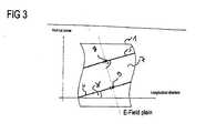
- Figure 3shows a top view of a radiating cable 1 and parallel slot edges 5, 6 of a slot-shaped aperture 7 provided therein.
- the highest field strength of said slot-shaped aperture 7is generated between two opposite points 8, 9 on the opposing slot edges 5, 6 at the shortest distance.
- This effectis caused by the different geometrical position of said two opposite points 8, 9 of the slot edges in the longitudinal direction. Since magnitude and phase of the E, H -field components at the two opposite points 8, 9 are different with respect to the longitudinal direction of the radiating cable, also the induced current components at the points 8, 9 at the same time are different. This causes the radiation of the E-field. In case of a small angle ⁇ or ⁇ ' between the shown slot section and the longitudinal axis of the radiating cable 1 the radiated E-Field vector is close to the vertical axis shown in figure 3 .
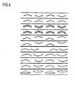
- Figure 4shows further shapes, orientations, and positions of angular apertures according to the present invention. That is, the present invention is not limited to the embodiments described above with respect to figures 2a, 2b, and 2c .
- the first example shown in figure 4shows angular apertures as described with respect to figure 2a .
- the second example of figure 4shows angular apertures aligned in one line and having the same orientation.
- Example three of figure 4is similar to example one wherein groups of two parallel apertures are arranged along the radiating cable.
- Example four of figure 4is similar to example two wherein groups of two parallel apertures are arranged along the radiating cable.
- Example fiveshows angular apertures having the same orientation along the radiating cable but being offset with respect to the longitudinal axis of the radiating cable.
- Example sixis similar to example five wherein the orientation of the angular apertures alternates along the length of the radiating cable.
- Example seven of figure 4again shows groups of angular apertures, each group consisting of two angular apertures having a different orientation and being arranged in one line along the longitudinal axis of the cable, wherein the distance between the groups of apertures is larger than the distance between two apertures forming one group.
- Example eightis similar to example one, wherein each aperture side has a curved shape. Also example nine is similar to example one, wherein each aperture side has a tapered shape.
- Example tenis similar to example nine, wherein the sides of the apertures are tapered towards the outer ends of the apertures and not towards the apex of the apertures (see example nine), where the aperture sides enclose an angle.
- Example eleven of figure 4which does not form part of the present invention, is similar to example one, wherein the angular apertures have a triangular shape.
- the shape of the plurality of apertures of the radiating cable according to the present inventionis not limited to any specific shape.
- the shape of the slots along the cablemay differ.
- the apertures or groups of aperturesare positioned periodically in the outer conductor of the radiating cable with the same distance between the apertures or group of apertures. All embodiments of the present invention have in common that the apertures in the outer conductor of the radiating cable have two sides enclosing an angle and an apex at the point where the two sides contact each other.
Landscapes
- Waveguide Aerials (AREA)
- Communication Cables (AREA)
- Insulated Conductors (AREA)
Abstract
Description
- The present invention relates to radiating high frequency lines. A radiating high frequency line is formed by a cable or a waveguide capable of radiating to the outside a portion of the electromagnetic energy which it transmits. In particular, the present invention relates to a radiating cable having apertures for generating electromagnetic (EM) fields outside of the cable and a communication system comprising such radiating cable.
- Radiating cables are generally formed from a coaxial cable comprising a conductive core defining the longitudinal axis of the cable and surrounded by an intermediate insulating sheath of a dielectric material, an outer conductor provided with regularly spaced apertures or slots for the passage of electromagnetic radiation, and a protective outer insulating jacket. By virtue of the apertures formed in the outer conductor, a portion of the power flowing in the cable and transmitted from a transmitting source is coupled to the exterior. The cable thus acts as an antenna and the power coupled to the exterior is called the radiated power. Due to their characteristics, radiating cables may be used under conditions in which signals radiated from a point source are attenuated rapidly.
- One of the properties required for a radiating cable is to ensure at least a minimum radiated power at a given distance from the longitudinal axis of the cable. Furthermore, the slots of such radiating cable should be repeated periodically so that they are in phase. Thus, it is possible to achieve good stability of the radiated power at a large distance from the cable over a frequency band. This stability makes it possible to satisfy minimum power requirements for the use of the cable in a reliable manner. If the stability is not guaranteed, major variations in the radiated power as a function of the point of reception along the length of the cable are such that it is difficult to ensure a minimum power value at a given distance from the cable. Moreover, these variations require the use of receivers which have a large dynamic range and which are accordingly costly.
- Conventional radiating cables function as a distributed antenna and facilitate radio communication where the usual free space propagation of electromagnetic waves is hampered, undesired or impossible, for example in tunnels, mines, buildings, alongside tracks or lines and in large complexes like exhibition grounds or airports. Slots in the outer conductor (e.g. formed of copper) allow a controlled portion of the internal RF energy to be radiated into the surrounding environment. Conversely, a signal transmitted near the cable will couple into the slots and will be carried along the cable length. Thus, a radiating cable may be used for both one-way and two-way communication systems.
EP 0 547 574 A1DE 100 62 591 A1 describes a radiating coaxial cable having rectangular slots in the outer conductor thereof, wherein the slots are aligned with the longitudinal axis of the cable and arranged spirally around the cable at a certain distance. However, slots aligned with the cable axis have a limited frequency bandwidth, since they resonate at comparably small frequencies which are often in the operational frequency band. In addition, such cable has a high longitudinal loss and stop bands at high frequencies limiting the usable bandwidth. Said high longitudinal loss requires active components such as bidirectional amplifiers to enable a reliable signal transmission in long cables, resulting in higher costs for a communication system using such radiating cable. Furthermore, the above described problems result in limited fields of application for the known radiating cables.US-A-3696433 describes a radiating cable comprising an outer conductor surrounding a longitudinal axis of the cable, wherein the outer conductor has a plurality of slot-shaped apertures and wherein each aperture has two slot-shaped sides enclosing an angle.FR-A-2096222 DE2845986A1 describes a radiating cable having a plurality of triangular or rhombic apertures.WO03/003511A FR-A-2135358 - It is therefore an object of the present invention to provide a radiating cable having a low longitudinal loss and broadband characteristics and enabling a cost effective communication system.
- This object and other objects are solved by the features of the independent claims. Preferred embodiments of the invention are described by the features of the dependent claims.
- The radiating cable according to the present invention is set out in
claim 1. - That is, the apertures of the radiating cable according to the present invention have an angular shape. With respect to the present invention the term enclosing means that an angle between said two aperture sides is less than 180° so that the enclosed angle is an acute angle or an obtuse angle.
- A radiating cable having apertures in its outer conductor enables the distribution of radio waves in confined areas where discrete antennas fail by radiating a homogeneous field along the cable. In addition, the radiating cable according to the present invention mainly generates a single polarized field thereby reducing the longitudinal loss of the cable to a minimum. In particular, a cable with only single polarization has basically a lower longitudinal loss than a cable with cross polarization, since in total less energy is radiated. Thus, a longer radiating cable without or having fewer active components may be provided. Furthermore, said single polarization provides the radiating cable according to the present invention with broadband characteristics so that multiple wireless services may be transmitted on the same infrastructure, since the apertures according to the present invention prevent stop bands at high frequencies.
- The direction of polarization depends on the application, in particular on the orientation of an external antenna communicating with the radiating cable towards the radiating cable. For example, in case that the antenna is mounted on the roof of a vehicle and is orthogonal with respect to the roof, the radiating cable running in parallel to the vehicle's driving direction should provide a vertically polarized field. In addition, the vertically polarized field provides the best field strength on vertically aligned antennas, if the cable runs in approximately the height in which external antennas are mounted.
- These two effects, that is, providing the appropriate direction of polarization (e.g. vertical) and reducing the longitudinal loss to a minimum, reduce the loss of the radiating cable to a minimum thus enabling a maximum length of a cable. Consequently, the number of required amplifiers is reduced resulting in lower costs and higher reliability. The broadband characteristics of the radiating cable according to the present invention resulting from less stop bands in useful frequency ranges provide a further cost reduction, since more wireless services can be transmitted over the same infrastructure.
- The angular apertures according to the present invention are placed along the longitudinal axis of the radiating cable to generate a phase shifted current flow at the aperture edges.
- Dimensions, orientations, and positions of the apertures may vary depending on the operational frequency band and a required coupling loss. All embodiments falling within the scope of the present invention have in common that both aperture sides enclose an angle at an apex of said aperture.
- The apertures according to the present invention are slot-shaped. That is, both sides of an aperture are oblong and enclose a specific angle, wherein the slot is continuous. For example, each aperture side is substantially rectangular. Alternatively, the aperture sides are curved.
- In addition, the lengths of the sides of an aperture may differ. Alternatively, the aperture sides are isosceles. For example, the length of an aperture side varies between 4 mm and 200 mm, preferably between 30 mm and 70 mm. In both cases, according to the present invention the plurality of apertures is arranged along the longitudinal axis of the radiating cable such that the aperture sides make the same angle with the longitudinal axis of the radiating cable.
- To generate an appropriate phase shift of the current flow at the aperture edges it is necessary to adapt the angle between the aperture sides and the longitudinal axis of the cable as well as the aperture width of a slot-shaped aperture. According to the present invention the slot-shaped apertures have a width between 0,5 mm and 20 mm, preferably between 1 mm and 2 mm. The angle between the longitudinal axis of the cable and an aperture side is between 0° and 90°.
- Known apertures in the outer conductor of the radiating cable are triangular. That is, the two sides of an aperture enclosing an angle are connected with each other at their free ends by a further side, so that the area within said three sides is triangular. Said triangular area forms an aperture in the outer conductor of a radiating cable. The triangle may have an arbitrary form. For example, the triangle is an isosceles triangle and the angles between the longitudinal axis of the cable and the isosceles sides of said triangle are equal. In such case, the basis of the triangle is in line with the longitudinal axis of the cable. However, the angles between the two sides of the triangle and the longitudinal axis of the cable may be different, and additionally the basis of the triangle may be oblique with respect to the longitudinal axis of the cable. Furthermore, the length of the three sides of the triangle may be different (scalene triangle) or equal (equilateral triangle).
- According to an embodiment of the present invention at least two apertures form a group of apertures, wherein such groups of apertures are periodically arranged along the length of the cable. For example, a group of apertures is formed by at least two slot-shaped angular apertures being in parallel with each other. According to a further example a group of apertures is formed by at least two apertures arranged in series along the length of the cable, wherein said at least two apertures have a specific distance from each other. In such case, the distance between the groups of apertures can be larger than the distance between the apertures forming one group of apertures.
- The present invention increases the possible fields of application of a radiating cable, since the bandwidth of such cable is significantly increased. In particular, the present invention provides for more bandwidth in the frequency ranges used for standard applications like GSM (870-960 MHz, 1710-1880 MHz), UMTS (1880-2200 MHz), WiMAX (e.g. 2400-3500 MHz), etc. Because of its broadband capability, a single radiating cable according to the present invention can handle multiple communication systems simultaneously. The radiating cable according to the present invention is optimized for high frequencies and digital transmission, where low coupling loss variations are required.
- According to a preferred embodiment of the present invention the radiating cable is a coaxial cable, comprising an inner conductor, which defines the longitudinal axis of the cable, an outer conductor surrounding the inner conductor, a dielectric sheath lying between the inner and outer conductors, and a jacket surrounding the outer conductor. According to the present invention the outer conductor of such coaxial cable comprises the plurality of angular apertures for enabling the transmission and reception of radio frequency (RF) signals. A coaxial cable having apertures in its outer conductor is also referred to as leaky coaxial cable.
- According to a further aspect a communication system comprising a radiating cable according to the present invention is provided. For example, the communication system is a tunnel communication system as used in subway and train tunnels. In such case it is preferred that the radiating cable according to the present invention radiates a vertically polarized RF field, since vehicle antennas of subways and trains are usually mounted on the top of their roofs and vertically polarized. By mounting the radiating cable in almost the same height as the vehicle antennas the best system performance is obtained when the cable provides a mainly vertically polarized field, since the vertically polarized field of the radiating cable provides the best field strength on vertical antennas. To create a vertically polarized RF field radiated from the radiating cable an aperture, in particular its position and shape, has to generate a phase shifted current flow on the aperture edges. The degree of phase shift depends on the aperture length along the longitudinal axis of the cable.
- As described above, the radiating cable according to the present invention mainly generates a single polarized field reducing the longitudinal loss to a minimum. This advantage is particularly useful in applications requiring long cables and a minimum of active components. For example, the tunnel communication system should consist of mainly passive components for providing a cost-effective and reliable system. According to the present invention the longitudinal loss is minimized, so that the cable length is maximized and the number of bidirectional amplifiers (active components) is minimized thus enabling a cost-effective and reliable communication system.
- Costs of the tunnel communication system or similar communication systems (e.g. in buildings) comprising a radiating cable according to the present invention are further reduced, since the radiating cable according to the present invention has broadband characteristics and thus enables the transmission of multiple wireless services on the same infrastructure.
- These and other aspects of the invention will be apparent from and elucidated with reference to the embodiments thereafter. It should be noted that the use of reference signs shall not be construed as limiting the scope of the invention.
- Figure 1a
- shows a simulation of transmission loss of a radiating cable according to
EP 0 547 574 A1 - Figure 1b
- shows a simulation of transmission loss of a radiating cable according to
DE 100 62 591 A1 having a length of 67m. - Figure 1c
- shows a simulation of transmission loss of a radiating cable according to the present invention having a length of 67m.
- Figure 2a
- shows a top view of a radiating cable having slot-shaped apertures according to a first embodiment of the present invention.
- Figure 2b
- shows a top view of a radiating cable having slot-shaped apertures.
- Figure 2c
- shows a top view of a radiating cable having slot-shaped apertures according to a second embodiment of the present invention.
- Figure 3
- shows a top view of a radiating cable and slot edges of a slot shaped aperture provided therein.
- Figure 4
- shows various shapes, orientations, and positions of angular apertures according to the present invention.
Figure 1a shows a simulation of transmission loss of a radiating cable according toEP 0 547 574 A1figure 1b shows a simulation of transmission loss of a radiating cable according toDE 100 62 591 A1 , andfigure 1 c shows a simulation of transmission loss of a radiating cable (leaky coaxial cable) according to the present invention, wherein each cable has a length of 67m. The shape and orientation of the apertures of the simulated radiating cable according to the present invention is described below with respect tofigure 2a . All cables have been simulated with main TEM mode to exclude the influence of higher propagation modes at frequencies over 2,7 GHz. The grey areas infigures 1a to 1c show the operational frequency bands of the respective cables. As can be seen fromfigures 1 a to 1 c the radiating cable according to the present invention provides better broadband characteristics, in particular at high frequencies, since stop bands are prevented by the aperture shape according to the present invention. Both prior art cables have stop bands at high frequencies so that their use in applications at high frequencies is limited or sometimes excluded.- A further simulation of the above radiating cables has shown that the radiating cable according to
EP 0 547 574 A1figure 1 a said cable has a stop band in said frequency range thus excluding its use. Said further simulation has also shown, that the radiating cable according toDE 100 62 591 A1 provides a polarization ratio higher than 13 dB between 1,4 and 2,0 GHz. In contrast thereto the radiating cable according to the present invention provides a polarization ratio higher than 13 dB between 1 and 3 GHz and thus better broadband characteristics. - The radiating cable according to the present invention whose simulation is shown in
figure 1c is, for example, a 1 ¼ inch cable. However, the angular apertures according to the present invention can also be used in cables having a different size. Appropriate cables have a size (diameter) between ½ inch and 1 5/8 inch. The operational frequency band of a cable having in its outer conductor a plurality of angular apertures according to the present invention is extended up to the WiMAX band at 3,5 GHz, interrupted by a small stop band at 2,6 GHz. In contrast thereto prior art radiating cables have several stop bands at frequencies higher than 2,3 GHz so that their use is limited or sometimes excluded. Figure 2a shows a top view of a radiatingcable 1 having slot-shapedapertures 2 according to a first embodiment of the present invention. The apertures are equalsided so that both sides of the apertures have the same length I. In addition, both sides of theaperture 2 are rectangular and have a width h. In the case shown infigure 2a the angles γ between thelongitudinal axis 3 of thecable 1 and each of the aperture sides are equal. As already mentioned above the degree of phase shift depends on the angle γ as well as the slot width h. In addition, the angle γ and the slot width h are responsible for the amount of radiated energy. That is, an increase of the angle γ and/or the width h of the rectangular aperture sides increases the amount of radiated and received RF energy.Figure 2b shows a top view of a radiatingcable 1 having slot-shapedapertures 2. Thelengths longitudinal axis 3 of thecable 1 differ from each other. This figure shows an example useful for understanding the inventionFigure 2c shows a top view of a radiatingcable 1 having slot-shapedapertures 2 according to a second embodiment of the present invention. According to said second embodiment the apex of the shown slot-shapedaperture 2 is formed by connecting the two aperture sides via an aperture section 4 which is in parallel to thelongitudinal axis 3 of the radiatingcable 1. Furthermore, the aperture section 4 has the identical width as the aperture sides. However, said aperture section 4 may also be oblique with respect to thelongitudinal axis 3 of the radiatingcable 1 and the slot width of the aperture section at the aperture apex may differ from the sloth width of the aperture sides. In addition, the aperture section 4 at the aperture apex may have any shape.- The length L1 of each aperture along the
longitudinal axis 3 of thecable 1, as shown infigures 2a, 2b, and 2c , is responsible for the stop band caused by the resonance frequency of the aperture 2 (L1 = λ/2). The lengths L2 and L3 are responsible for the selection of the operational frequency interval at high frequencies above 1700 MHz, wherein the lengths L2 indicates the distance between a first and a second aperture and the lengths L3 indicates the distance between a first and a third aperture. - By varying the parameters described above it is possible to tune the radiating properties of the radiating cable as required. Depending on the application in which the radiating cable is used the radiating energy can be increased or decreased and the operational frequency bands can be shifted.
- As can be seen from
figure 2a the orientation of the slot-shapedapertures 2 with respect to thelongitudinal axis 3 of the radiatingcable 1 is alternated by 180°. In contrast theretofigure 2b shows that the plurality of slot-shapedapertures 2 can also be oriented in the same direction along thelongitudinal axis 3 of thecable 1. Figure 3 shows a top view of a radiatingcable 1 and parallel slot edges 5, 6 of a slot-shaped aperture 7 provided therein. The highest field strength of said slot-shaped aperture 7 is generated between twoopposite points 8, 9 on the opposing slot edges 5, 6 at the shortest distance. This effect is caused by the different geometrical position of said twoopposite points 8, 9 of the slot edges in the longitudinal direction. Since magnitude and phase of the E, H -field components at the twoopposite points 8, 9 are different with respect to the longitudinal direction of the radiating cable, also the induced current components at thepoints 8, 9 at the same time are different. This causes the radiation of the E-field. In case of a small angle γ or γ' between the shown slot section and the longitudinal axis of the radiatingcable 1 the radiated E-Field vector is close to the vertical axis shown infigure 3 .Figure 4 shows further shapes, orientations, and positions of angular apertures according to the present invention. That is, the present invention is not limited to the embodiments described above with respect tofigures 2a, 2b, and 2c . The first example shown infigure 4 (from top to bottom) shows angular apertures as described with respect tofigure 2a . The second example offigure 4 shows angular apertures aligned in one line and having the same orientation. Example three offigure 4 is similar to example one wherein groups of two parallel apertures are arranged along the radiating cable. Example four offigure 4 is similar to example two wherein groups of two parallel apertures are arranged along the radiating cable. Example five shows angular apertures having the same orientation along the radiating cable but being offset with respect to the longitudinal axis of the radiating cable. Example six is similar to example five wherein the orientation of the angular apertures alternates along the length of the radiating cable. Example seven offigure 4 again shows groups of angular apertures, each group consisting of two angular apertures having a different orientation and being arranged in one line along the longitudinal axis of the cable, wherein the distance between the groups of apertures is larger than the distance between two apertures forming one group. Example eight is similar to example one, wherein each aperture side has a curved shape. Also example nine is similar to example one, wherein each aperture side has a tapered shape. Example ten is similar to example nine, wherein the sides of the apertures are tapered towards the outer ends of the apertures and not towards the apex of the apertures (see example nine), where the aperture sides enclose an angle. Example eleven offigure 4 , which does not form part of the present invention, is similar to example one, wherein the angular apertures have a triangular shape. As can be learned fromfigure 4 , the shape of the plurality of apertures of the radiating cable according to the present invention is not limited to any specific shape. In addition, the shape of the slots along the cable may differ. Preferably, the apertures or groups of apertures are positioned periodically in the outer conductor of the radiating cable with the same distance between the apertures or group of apertures. All embodiments of the present invention have in common that the apertures in the outer conductor of the radiating cable have two sides enclosing an angle and an apex at the point where the two sides contact each other.
Claims (8)
- Radiating cable (1) for radiating electromagnetic energy in a frequency band, comprising an outer conductor surrounding a longitudinal axis (3) of the cable. (1), wherein the outer conductor has a plurality of slot-shaped apertures (2) and wherein each slot-shaped aperture (2) has two slot-shaped sides enclos-ing an angle (α) smaller than 180°,characterized in that the slot-shaped aperture sides make the same angle (γ) with the longitudinal axis (3) of the cable (1).
- Radiating cable (1) according to claim 1, wherein each aperture side is substantially rectangular.
- Radiating cable (1) according to claim 1, wherein each aperture side is curved.
- Radiating cable (1) according to any of claims 1 to 3, wherein the apertures (2) have a width (h) between 0,5 mm and 20 mm, preferably between 1 mm and 2 mm.
- Radiating cable (1) according to any of the preceding claims, wherein the aperture sides enclosing the angle (α) are isosceles.
- Radiating cable (1) according to any of the preceding claims, wherein the angle (γ) between the longitudinal axis (3) of the cable (1) and an aperture side is between 0° and 90°.
- Radiating cable (1) according to any of the preceding claims, wherein a distance between the apertures (2) or groups of apertures is equal.
- Communication system comprising a radiating cable (1) according to any of the preceding claims.
Priority Applications (3)
| Application Number | Priority Date | Filing Date | Title |
|---|---|---|---|
| AT08290922TATE497269T1 (en) | 2008-09-30 | 2008-09-30 | RADIANT CABLE |
| DE602008004776TDE602008004776D1 (en) | 2008-09-30 | 2008-09-30 | Radiant cable |
| EP08290922AEP2169769B1 (en) | 2008-09-30 | 2008-09-30 | Radiating cable |
Applications Claiming Priority (1)
| Application Number | Priority Date | Filing Date | Title |
|---|---|---|---|
| EP08290922AEP2169769B1 (en) | 2008-09-30 | 2008-09-30 | Radiating cable |
Publications (2)
| Publication Number | Publication Date |
|---|---|
| EP2169769A1 EP2169769A1 (en) | 2010-03-31 |
| EP2169769B1true EP2169769B1 (en) | 2011-01-26 |
Family
ID=40256923
Family Applications (1)
| Application Number | Title | Priority Date | Filing Date |
|---|---|---|---|
| EP08290922AActiveEP2169769B1 (en) | 2008-09-30 | 2008-09-30 | Radiating cable |
Country Status (3)
| Country | Link |
|---|---|
| EP (1) | EP2169769B1 (en) |
| AT (1) | ATE497269T1 (en) |
| DE (1) | DE602008004776D1 (en) |
Cited By (4)
| Publication number | Priority date | Publication date | Assignee | Title |
|---|---|---|---|---|
| EP3714551A1 (en)* | 2017-11-21 | 2020-09-30 | Telefonaktiebolaget LM Ericsson (publ) | Improved antenna arrangement for distributed massive mimo |
| US11777619B2 (en) | 2020-02-10 | 2023-10-03 | Telefonaktiebolaget Lm Ericsson (Publ) | Dielectric waveguide signal transfer function compensation |
| US11916625B2 (en) | 2016-12-09 | 2024-02-27 | Telefonaktiebolaget Lm Ericsson (Publ) | Antenna arrangement for distributed massive MIMO |
| US12255701B2 (en) | 2020-02-10 | 2025-03-18 | Telefonaktiebolaget Lm Ericsson (Publ) | Method and apparatus for radio communications |
Families Citing this family (8)
| Publication number | Priority date | Publication date | Assignee | Title |
|---|---|---|---|---|
| EP2495882A1 (en)* | 2011-02-28 | 2012-09-05 | Alcatel Lucent | Distributed antenna system |
| EP2759068B1 (en)* | 2011-09-21 | 2020-01-01 | Empire Technology Development LLC | Doppler-nulling traveling-wave antenna relays for high-speed vehicular communictions |
| EP3032637B1 (en)* | 2014-12-13 | 2020-05-27 | Nokia Shanghai Bell Co., Ltd. | Radiating cable and method of manufacturing a radiating cable |
| EP3032638B1 (en)* | 2014-12-13 | 2020-04-22 | Nokia Shanghai Bell Co., Ltd. | Radiating cable and method of manufacturing a radiating cable |
| CN106848521B (en)* | 2017-02-24 | 2022-05-10 | 通号电缆集团有限公司 | Dual-polarization leaky waveguide |
| IT202000005983A1 (en)* | 2020-03-20 | 2021-09-20 | Prysmian Spa | Radiant coaxial cable |
| CN112083237B (en)* | 2020-07-31 | 2021-06-29 | 西安交通大学 | A time-domain measurement method and system for broadband characteristics of large-scale electrical equipment |
| CN116190954A (en)* | 2023-02-17 | 2023-05-30 | 江苏亨鑫科技有限公司 | Double-parallel flame-retardant leaky coaxial cable |
Family Cites Families (8)
| Publication number | Priority date | Publication date | Assignee | Title |
|---|---|---|---|---|
| JPS5122683B1 (en)* | 1970-06-12 | 1976-07-12 | ||
| US3696433A (en)* | 1970-07-17 | 1972-10-03 | Teledyne Ryan Aeronautical Co | Resonant slot antenna structure |
| IT960076B (en)* | 1971-05-06 | 1973-11-20 | Sumitomo Electric Industries | DISPERSION COAXIAL CABLE WITH SHAPED SLOTS IN THE EXTERNAL CONDUCTOR |
| US3795915A (en)* | 1972-10-20 | 1974-03-05 | Sumitomo Electric Industries | Leaky coaxial cable |
| DE2845986A1 (en)* | 1978-08-24 | 1980-03-06 | Daetwyler Ag | Coaxial HF cable - with outer conductor consisting of PTFE coated metal tape with rhomboidal perforations |
| FR2685549B1 (en) | 1991-12-19 | 1994-01-28 | Alcatel Cable | HIGH RADIATION FREQUENCY LINE. |
| US6480163B1 (en) | 1999-12-16 | 2002-11-12 | Andrew Corporation | Radiating coaxial cable having helically diposed slots and radio communication system using same |
| CN1520628A (en)* | 2001-06-27 | 2004-08-11 | 株式会社Emw天线 | Antenna for portable radio communication equipment |
- 2008
- 2008-09-30EPEP08290922Apatent/EP2169769B1/enactiveActive
- 2008-09-30DEDE602008004776Tpatent/DE602008004776D1/enactiveActive
- 2008-09-30ATAT08290922Tpatent/ATE497269T1/ennot_activeIP Right Cessation
Cited By (5)
| Publication number | Priority date | Publication date | Assignee | Title |
|---|---|---|---|---|
| US11916625B2 (en) | 2016-12-09 | 2024-02-27 | Telefonaktiebolaget Lm Ericsson (Publ) | Antenna arrangement for distributed massive MIMO |
| EP3714551A1 (en)* | 2017-11-21 | 2020-09-30 | Telefonaktiebolaget LM Ericsson (publ) | Improved antenna arrangement for distributed massive mimo |
| US11799524B2 (en) | 2017-11-21 | 2023-10-24 | Telefonaktiebolaget Lm Ericsson (Publ) | Antenna arrangement for distributed massive MIMO |
| US11777619B2 (en) | 2020-02-10 | 2023-10-03 | Telefonaktiebolaget Lm Ericsson (Publ) | Dielectric waveguide signal transfer function compensation |
| US12255701B2 (en) | 2020-02-10 | 2025-03-18 | Telefonaktiebolaget Lm Ericsson (Publ) | Method and apparatus for radio communications |
Also Published As
| Publication number | Publication date |
|---|---|
| ATE497269T1 (en) | 2011-02-15 |
| DE602008004776D1 (en) | 2011-03-10 |
| EP2169769A1 (en) | 2010-03-31 |
Similar Documents
| Publication | Publication Date | Title |
|---|---|---|
| EP2169769B1 (en) | Radiating cable | |
| US7286099B1 (en) | Rotation-independent helical antenna | |
| US7405699B2 (en) | Multiple input multiple output antenna | |
| US7471258B2 (en) | Coaxial cable having high radiation efficiency | |
| WO2015029946A1 (en) | Antenna and sector antenna | |
| US8890758B2 (en) | Antenna arrangement | |
| US9515386B2 (en) | Antenna arrangement | |
| KR100766182B1 (en) | Radial leakage coaxial cable | |
| CN114094294A (en) | Leakage cable | |
| SG174388A1 (en) | Vhf/uhf broadband dual channel antenna | |
| US20080150806A1 (en) | Multiple input multiple output antenna | |
| CN109713440A (en) | A kind of antenna element and array antenna | |
| US10855114B2 (en) | Wireless power transmission system using patch antenna | |
| US12230885B2 (en) | RF device with isolated antennas | |
| KR100817981B1 (en) | Broadband leakage coaxial cable | |
| US4987423A (en) | Wide band loop antenna with disymmetrical feeding, notably antenna for transmission, and array antenna formed by several such antennas | |
| KR100769398B1 (en) | Leakage Coaxial Cable for Mobile Communication | |
| US20060119529A1 (en) | Ultra wideband antenna | |
| KR20120033234A (en) | Display device | |
| KR101043855B1 (en) | Cable Type Broadband Antenna System | |
| KR100780147B1 (en) | Broadband leakage coaxial cable | |
| KR100837006B1 (en) | Broadband leakage coaxial cable | |
| JP2015080010A (en) | Antenna and diversity communication system | |
| KR20070082228A (en) | Broadband leakage coaxial cable | |
| JP7549476B2 (en) | Leaky Coaxial Cable |
Legal Events
| Date | Code | Title | Description |
|---|---|---|---|
| PUAI | Public reference made under article 153(3) epc to a published international application that has entered the european phase | Free format text:ORIGINAL CODE: 0009012 | |
| 17P | Request for examination filed | Effective date:20090312 | |
| AK | Designated contracting states | Kind code of ref document:A1 Designated state(s):AT BE BG CH CY CZ DE DK EE ES FI FR GB GR HR HU IE IS IT LI LT LU LV MC MT NL NO PL PT RO SE SI SK TR | |
| AX | Request for extension of the european patent | Extension state:AL BA MK RS | |
| GRAP | Despatch of communication of intention to grant a patent | Free format text:ORIGINAL CODE: EPIDOSNIGR1 | |
| AKX | Designation fees paid | Designated state(s):AT BE BG CH CY CZ DE DK EE ES FI FR GB GR HR HU IE IS IT LI LT LU LV MC MT NL NO PL PT RO SE SI SK TR | |
| GRAS | Grant fee paid | Free format text:ORIGINAL CODE: EPIDOSNIGR3 | |
| GRAA | (expected) grant | Free format text:ORIGINAL CODE: 0009210 | |
| AK | Designated contracting states | Kind code of ref document:B1 Designated state(s):AT BE BG CH CY CZ DE DK EE ES FI FR GB GR HR HU IE IS IT LI LT LU LV MC MT NL NO PL PT RO SE SI SK TR | |
| REG | Reference to a national code | Ref country code:GB Ref legal event code:FG4D | |
| REG | Reference to a national code | Ref country code:CH Ref legal event code:EP | |
| REG | Reference to a national code | Ref country code:IE Ref legal event code:FG4D | |
| REF | Corresponds to: | Ref document number:602008004776 Country of ref document:DE Date of ref document:20110310 Kind code of ref document:P | |
| REG | Reference to a national code | Ref country code:DE Ref legal event code:R096 Ref document number:602008004776 Country of ref document:DE Effective date:20110310 | |
| REG | Reference to a national code | Ref country code:NL Ref legal event code:VDEP Effective date:20110126 | |
| LTIE | Lt: invalidation of european patent or patent extension | Effective date:20110126 | |
| PG25 | Lapsed in a contracting state [announced via postgrant information from national office to epo] | Ref country code:LT Free format text:LAPSE BECAUSE OF FAILURE TO SUBMIT A TRANSLATION OF THE DESCRIPTION OR TO PAY THE FEE WITHIN THE PRESCRIBED TIME-LIMIT Effective date:20110126 Ref country code:SE Free format text:LAPSE BECAUSE OF FAILURE TO SUBMIT A TRANSLATION OF THE DESCRIPTION OR TO PAY THE FEE WITHIN THE PRESCRIBED TIME-LIMIT Effective date:20110126 Ref country code:NO Free format text:LAPSE BECAUSE OF FAILURE TO SUBMIT A TRANSLATION OF THE DESCRIPTION OR TO PAY THE FEE WITHIN THE PRESCRIBED TIME-LIMIT Effective date:20110426 Ref country code:PT Free format text:LAPSE BECAUSE OF FAILURE TO SUBMIT A TRANSLATION OF THE DESCRIPTION OR TO PAY THE FEE WITHIN THE PRESCRIBED TIME-LIMIT Effective date:20110526 Ref country code:LV Free format text:LAPSE BECAUSE OF FAILURE TO SUBMIT A TRANSLATION OF THE DESCRIPTION OR TO PAY THE FEE WITHIN THE PRESCRIBED TIME-LIMIT Effective date:20110126 Ref country code:ES Free format text:LAPSE BECAUSE OF FAILURE TO SUBMIT A TRANSLATION OF THE DESCRIPTION OR TO PAY THE FEE WITHIN THE PRESCRIBED TIME-LIMIT Effective date:20110507 Ref country code:HR Free format text:LAPSE BECAUSE OF FAILURE TO SUBMIT A TRANSLATION OF THE DESCRIPTION OR TO PAY THE FEE WITHIN THE PRESCRIBED TIME-LIMIT Effective date:20110126 Ref country code:IS Free format text:LAPSE BECAUSE OF FAILURE TO SUBMIT A TRANSLATION OF THE DESCRIPTION OR TO PAY THE FEE WITHIN THE PRESCRIBED TIME-LIMIT Effective date:20110526 Ref country code:GR Free format text:LAPSE BECAUSE OF FAILURE TO SUBMIT A TRANSLATION OF THE DESCRIPTION OR TO PAY THE FEE WITHIN THE PRESCRIBED TIME-LIMIT Effective date:20110427 | |
| PG25 | Lapsed in a contracting state [announced via postgrant information from national office to epo] | Ref country code:FI Free format text:LAPSE BECAUSE OF FAILURE TO SUBMIT A TRANSLATION OF THE DESCRIPTION OR TO PAY THE FEE WITHIN THE PRESCRIBED TIME-LIMIT Effective date:20110126 Ref country code:CY Free format text:LAPSE BECAUSE OF FAILURE TO SUBMIT A TRANSLATION OF THE DESCRIPTION OR TO PAY THE FEE WITHIN THE PRESCRIBED TIME-LIMIT Effective date:20110126 Ref country code:NL Free format text:LAPSE BECAUSE OF FAILURE TO SUBMIT A TRANSLATION OF THE DESCRIPTION OR TO PAY THE FEE WITHIN THE PRESCRIBED TIME-LIMIT Effective date:20110126 Ref country code:AT Free format text:LAPSE BECAUSE OF FAILURE TO SUBMIT A TRANSLATION OF THE DESCRIPTION OR TO PAY THE FEE WITHIN THE PRESCRIBED TIME-LIMIT Effective date:20110126 Ref country code:PL Free format text:LAPSE BECAUSE OF FAILURE TO SUBMIT A TRANSLATION OF THE DESCRIPTION OR TO PAY THE FEE WITHIN THE PRESCRIBED TIME-LIMIT Effective date:20110126 Ref country code:BG Free format text:LAPSE BECAUSE OF FAILURE TO SUBMIT A TRANSLATION OF THE DESCRIPTION OR TO PAY THE FEE WITHIN THE PRESCRIBED TIME-LIMIT Effective date:20110426 Ref country code:BE Free format text:LAPSE BECAUSE OF FAILURE TO SUBMIT A TRANSLATION OF THE DESCRIPTION OR TO PAY THE FEE WITHIN THE PRESCRIBED TIME-LIMIT Effective date:20110126 Ref country code:SI Free format text:LAPSE BECAUSE OF FAILURE TO SUBMIT A TRANSLATION OF THE DESCRIPTION OR TO PAY THE FEE WITHIN THE PRESCRIBED TIME-LIMIT Effective date:20110126 | |
| PG25 | Lapsed in a contracting state [announced via postgrant information from national office to epo] | Ref country code:DK Free format text:LAPSE BECAUSE OF FAILURE TO SUBMIT A TRANSLATION OF THE DESCRIPTION OR TO PAY THE FEE WITHIN THE PRESCRIBED TIME-LIMIT Effective date:20110126 Ref country code:EE Free format text:LAPSE BECAUSE OF FAILURE TO SUBMIT A TRANSLATION OF THE DESCRIPTION OR TO PAY THE FEE WITHIN THE PRESCRIBED TIME-LIMIT Effective date:20110126 | |
| PG25 | Lapsed in a contracting state [announced via postgrant information from national office to epo] | Ref country code:CZ Free format text:LAPSE BECAUSE OF FAILURE TO SUBMIT A TRANSLATION OF THE DESCRIPTION OR TO PAY THE FEE WITHIN THE PRESCRIBED TIME-LIMIT Effective date:20110126 Ref country code:RO Free format text:LAPSE BECAUSE OF FAILURE TO SUBMIT A TRANSLATION OF THE DESCRIPTION OR TO PAY THE FEE WITHIN THE PRESCRIBED TIME-LIMIT Effective date:20110126 Ref country code:SK Free format text:LAPSE BECAUSE OF FAILURE TO SUBMIT A TRANSLATION OF THE DESCRIPTION OR TO PAY THE FEE WITHIN THE PRESCRIBED TIME-LIMIT Effective date:20110126 | |
| PLBE | No opposition filed within time limit | Free format text:ORIGINAL CODE: 0009261 | |
| STAA | Information on the status of an ep patent application or granted ep patent | Free format text:STATUS: NO OPPOSITION FILED WITHIN TIME LIMIT | |
| 26N | No opposition filed | Effective date:20111027 | |
| REG | Reference to a national code | Ref country code:DE Ref legal event code:R097 Ref document number:602008004776 Country of ref document:DE Effective date:20111027 | |
| REG | Reference to a national code | Ref country code:CH Ref legal event code:PCOW Free format text:ALCATEL LUCENT;3, AVENUE OCTAVE GREARD;75007 PARIS (FR) | |
| PG25 | Lapsed in a contracting state [announced via postgrant information from national office to epo] | Ref country code:MC Free format text:LAPSE BECAUSE OF NON-PAYMENT OF DUE FEES Effective date:20110930 | |
| PG25 | Lapsed in a contracting state [announced via postgrant information from national office to epo] | Ref country code:IT Free format text:LAPSE BECAUSE OF FAILURE TO SUBMIT A TRANSLATION OF THE DESCRIPTION OR TO PAY THE FEE WITHIN THE PRESCRIBED TIME-LIMIT Effective date:20110126 | |
| REG | Reference to a national code | Ref country code:IE Ref legal event code:MM4A | |
| PG25 | Lapsed in a contracting state [announced via postgrant information from national office to epo] | Ref country code:IE Free format text:LAPSE BECAUSE OF NON-PAYMENT OF DUE FEES Effective date:20110930 | |
| PG25 | Lapsed in a contracting state [announced via postgrant information from national office to epo] | Ref country code:MT Free format text:LAPSE BECAUSE OF FAILURE TO SUBMIT A TRANSLATION OF THE DESCRIPTION OR TO PAY THE FEE WITHIN THE PRESCRIBED TIME-LIMIT Effective date:20110126 | |
| REG | Reference to a national code | Ref country code:CH Ref legal event code:PL | |
| PG25 | Lapsed in a contracting state [announced via postgrant information from national office to epo] | Ref country code:LU Free format text:LAPSE BECAUSE OF NON-PAYMENT OF DUE FEES Effective date:20110930 | |
| PG25 | Lapsed in a contracting state [announced via postgrant information from national office to epo] | Ref country code:CH Free format text:LAPSE BECAUSE OF NON-PAYMENT OF DUE FEES Effective date:20120930 Ref country code:LI Free format text:LAPSE BECAUSE OF NON-PAYMENT OF DUE FEES Effective date:20120930 | |
| PG25 | Lapsed in a contracting state [announced via postgrant information from national office to epo] | Ref country code:TR Free format text:LAPSE BECAUSE OF FAILURE TO SUBMIT A TRANSLATION OF THE DESCRIPTION OR TO PAY THE FEE WITHIN THE PRESCRIBED TIME-LIMIT Effective date:20110126 | |
| PG25 | Lapsed in a contracting state [announced via postgrant information from national office to epo] | Ref country code:HU Free format text:LAPSE BECAUSE OF FAILURE TO SUBMIT A TRANSLATION OF THE DESCRIPTION OR TO PAY THE FEE WITHIN THE PRESCRIBED TIME-LIMIT Effective date:20110126 | |
| REG | Reference to a national code | Ref country code:FR Ref legal event code:GC Effective date:20131018 | |
| REG | Reference to a national code | Ref country code:FR Ref legal event code:RG Effective date:20141016 | |
| REG | Reference to a national code | Ref country code:FR Ref legal event code:CA Effective date:20150521 | |
| REG | Reference to a national code | Ref country code:FR Ref legal event code:CA Effective date:20150521 | |
| REG | Reference to a national code | Ref country code:FR Ref legal event code:PLFP Year of fee payment:8 | |
| REG | Reference to a national code | Ref country code:FR Ref legal event code:PLFP Year of fee payment:9 | |
| REG | Reference to a national code | Ref country code:FR Ref legal event code:PLFP Year of fee payment:10 | |
| REG | Reference to a national code | Ref country code:FR Ref legal event code:PLFP Year of fee payment:11 | |
| REG | Reference to a national code | Ref country code:DE Ref legal event code:R082 Ref document number:602008004776 Country of ref document:DE Representative=s name:DREISS PATENTANWAELTE PARTG MBB, DE | |
| REG | Reference to a national code | Ref country code:DE Ref legal event code:R081 Ref document number:602008004776 Country of ref document:DE Owner name:RADIO FREQUENCY SYSTEMS GESELLSCHAFT MIT BESCH, DE Free format text:FORMER OWNER: ALCATEL LUCENT, PARIS, FR | |
| PGFP | Annual fee paid to national office [announced via postgrant information from national office to epo] | Ref country code:GB Payment date:20240917 Year of fee payment:17 | |
| PGFP | Annual fee paid to national office [announced via postgrant information from national office to epo] | Ref country code:FR Payment date:20240924 Year of fee payment:17 | |
| PGFP | Annual fee paid to national office [announced via postgrant information from national office to epo] | Ref country code:DE Payment date:20241112 Year of fee payment:17 | |
| REG | Reference to a national code | Ref country code:GB Ref legal event code:732E Free format text:REGISTERED BETWEEN 20250306 AND 20250312 |