EP2168690B1 - Korund distributor - Google Patents
Korund distributorDownload PDFInfo
- Publication number
- EP2168690B1 EP2168690B1EP08017203AEP08017203AEP2168690B1EP 2168690 B1EP2168690 B1EP 2168690B1EP 08017203 AEP08017203 AEP 08017203AEP 08017203 AEP08017203 AEP 08017203AEP 2168690 B1EP2168690 B1EP 2168690B1
- Authority
- EP
- European Patent Office
- Prior art keywords
- roller
- particles
- distributing element
- scatter
- opening
- Prior art date
- Legal status (The legal status is an assumption and is not a legal conclusion. Google has not performed a legal analysis and makes no representation as to the accuracy of the status listed.)
- Active
Links
- TWNQGVIAIRXVLR-UHFFFAOYSA-Noxo(oxoalumanyloxy)alumaneChemical compoundO=[Al]O[Al]=OTWNQGVIAIRXVLR-UHFFFAOYSA-N0.000title1
- 239000002245particleSubstances0.000claimsdescription72
- 229910000831SteelInorganic materials0.000claimsdescription22
- 239000010959steelSubstances0.000claimsdescription22
- 238000005299abrasionMethods0.000claimsdescription13
- 229910052593corundumInorganic materials0.000claimsdescription10
- 239000010431corundumSubstances0.000claimsdescription10
- 239000002023woodSubstances0.000claimsdescription10
- 239000000463materialSubstances0.000claimsdescription5
- 238000000034methodMethods0.000claimsdescription4
- 230000005484gravityEffects0.000claims1
- 238000009826distributionMethods0.000description42
- 229920005989resinPolymers0.000description6
- 239000011347resinSubstances0.000description6
- 239000011248coating agentSubstances0.000description5
- 238000000576coating methodMethods0.000description5
- 238000010073coating (rubber)Methods0.000description3
- 238000003892spreadingMethods0.000description3
- 229920001971elastomerPolymers0.000description2
- 230000033001locomotionEffects0.000description2
- 239000011159matrix materialSubstances0.000description2
- 229920000877Melamine resinPolymers0.000description1
- 239000004640Melamine resinSubstances0.000description1
- 229920003180amino resinPolymers0.000description1
- 230000005540biological transmissionEffects0.000description1
- 230000001680brushing effectEffects0.000description1
- 238000007599dischargingMethods0.000description1
- 239000006185dispersionSubstances0.000description1
- 238000001035dryingMethods0.000description1
- 230000000694effectsEffects0.000description1
- 239000000806elastomerSubstances0.000description1
- -1for exampleSubstances0.000description1
- 238000005470impregnationMethods0.000description1
- 238000011835investigationMethods0.000description1
- 238000004519manufacturing processMethods0.000description1
- 239000004033plasticSubstances0.000description1
- 229920003023plasticPolymers0.000description1
- 238000003825pressingMethods0.000description1
- 125000002924primary amino groupChemical group[H]N([H])*0.000description1
- 150000003377silicon compoundsChemical class0.000description1
- 238000003860storageMethods0.000description1
- 239000004636vulcanized rubberSubstances0.000description1
Images


Classifications
- B—PERFORMING OPERATIONS; TRANSPORTING
- B05—SPRAYING OR ATOMISING IN GENERAL; APPLYING FLUENT MATERIALS TO SURFACES, IN GENERAL
- B05C—APPARATUS FOR APPLYING FLUENT MATERIALS TO SURFACES, IN GENERAL
- B05C19/00—Apparatus specially adapted for applying particulate materials to surfaces
- B05C19/04—Apparatus specially adapted for applying particulate materials to surfaces the particulate material being projected, poured or allowed to flow onto the surface of the work
- B—PERFORMING OPERATIONS; TRANSPORTING
- B32—LAYERED PRODUCTS
- B32B—LAYERED PRODUCTS, i.e. PRODUCTS BUILT-UP OF STRATA OF FLAT OR NON-FLAT, e.g. CELLULAR OR HONEYCOMB, FORM
- B32B21/00—Layered products comprising a layer of wood, e.g. wood board, veneer, wood particle board
- B—PERFORMING OPERATIONS; TRANSPORTING
- B65—CONVEYING; PACKING; STORING; HANDLING THIN OR FILAMENTARY MATERIAL
- B65G—TRANSPORT OR STORAGE DEVICES, e.g. CONVEYORS FOR LOADING OR TIPPING, SHOP CONVEYOR SYSTEMS OR PNEUMATIC TUBE CONVEYORS
- B65G31/00—Mechanical throwing machines for articles or solid materials
- B65G31/04—Mechanical throwing machines for articles or solid materials comprising discs, drums, or like rotary impellers
Definitions
- the present inventionrelates to a device for scattering particles, in particular to a surface of wood-based panels or impregnates, and to a method for scattering particles.
- a spreaderis known, with which the surface of a floor panel can be sprinkled with abrasion-resistant particles.
- the abrasion-resistant particlesconsist for example of corundum or silicon compounds and are sprinkled onto the still moist decorative paper of a known laminate panel. After curing the decorative paper under pressure and temperature thus creates a very resistant surface.
- the devicecomprises two rollers, a steel roller and a brush roller, which are arranged parallel to each other.
- the steel rolleris provided with small recesses or pockets on its upper side and rotatably mounted. Above the steel roller is a container containing the corundum particles and this gives off controlled on the rotating top of the steel roller.
- the emitted corundum particlescollect in the depressions or pockets of the steel roller and are doctored by the rotation of the roller and transported on.
- the brush rolleris also rotatably mounted and laterally arranged in parallel adjacent the steel roller so that its brushes can brush out the filled recesses or pockets on the surface of the steel roller.
- the apparatusfurther comprises a conveyor with which the panels or impregnates can be guided past the rollers at a defined speed .
- the term "impregnate"is a common term in the industry, which refers to resin-impregnated papers, such as the decorative paper mentioned above. For example, these papers serve as a component or intermediate in the manufacture of laminates.
- laminate panelsusually consist of a four to eight millimeters thick backing plate made of MDF or HDF material, on top of which a printed with a decor and impregnated with a resin paper, a so-called decor paper, applied under pressure and temperature.
- a resin-impregnated Reifenzugpapieris set up to counteract a delay of the support plate by the decorative paper applied.
- an abrasion-resistant layerconsisting of small corundum particles (embedded in a resin matrix) embedded in a resin matrix must be applied to give the surface the necessary durability.
- Another prior artis in document DE-A-198 17 805 described.
- the objectis to provide a device for scattering particles on a surface, which eliminates or reduces the above-mentioned disadvantages of the prior art.
- the objectis an apparatus to provide that allows a well-dosed dispersion and is subject to less wear and therefore can be operated more cost-effectively.
- itis the object of the invention to provide a device for sprinkling abrasion-resistant particles on the surface of wood-based panels, in particular of laminate panels, as described above.
- the device according to the invention for spreading abrasion-resistant particles onto a surfacecomprises the features of claim 1.
- corundum particlesare sprinkled on the surface of wood-based panels, impregnates and the like, in particular laminate panels
- the apparatuscomprises a container for the particles to be scattered with at least one scattering opening for dispensing particles and a roller-like distribution element with a curved surface.
- the scattering openingis arranged above the curved surface of the distribution element and preferably extends parallel to the longitudinal axis of the roller-like distribution element.
- the length of the scattering openingis preferably selected on the basis of the size of the surface to be spread, this also applies to the length of the roller-like distribution element.
- the roller-like distribution element and the scattering openingmust likewise be at least approximately two meters long.
- the scattering openingis preferably a gap (scattering gap).
- the devicecomprises means with which the roller-like distribution element can be vibrated in the longitudinal direction, so that the particles fall from the scattering opening over the curved surface away in the direction of the surface to be spread.
- the vibration of the distribution elementpreferably fulfills several functions. On the one hand, it ensures even distribution or scattering of the particles on the surface to be spread. On the other hand eliminates by the vibration the need to rotate the roller-like distribution element, and the need for a brush roller with which in the prior art, the particles were brushed from the surface of the distribution element. Surprisingly, it has been found that no or little wear occurs on the surface of the distributor element due to the vibration of the distributor element. Therefore, abrasion-resistant particles, such as, for example, corundum particles, can be processed particularly well with the device of the invention.
- the container for the particles to be scatteredis to be understood widely and includes any type of storage possibility with which particles to be scattered can be provided in the sense of the invention.
- Essential for the inventionis rather the scattering opening or the spreading gap and its orientation to the roller-like distribution element.
- the roller-like distribution elementis preferably a roller, and in particular a steel roller, since such rollers are easy and relatively inexpensive to procure.
- the roller-like distribution elementcould therefore also consist of a roller which is quasi "cut through" in the longitudinal direction, i. H. for example, has a semicircular, three-quarter circular or quarter-circular cross-section.
- the curvature of the curved surfaceshould preferably be a circular arc.
- this circular arcshould have a center angle (also called center angle) of at least seventy degrees, preferably at least eighty degrees, more preferably at least about ninety degrees, and most preferably at least about one hundred degrees.
- the curved surface of the roller-like distribution elementis provided with a coating.
- This coatingis a rubber which is applied in a known manner to the surface of the distribution element, in particular vulcanized.
- the distribution elementis preferably made of steel in all the embodiments described herein.
- the Applicanthas surprisingly found that a gumming of the surface the roller-like distribution element improves the uniformity of the scattering of the particles compared to an untreated steel surface.
- the rubber coatinghas significantly better wear properties compared to a pure steel surface. This is especially true when using abrasion-resistant particles, such as corundum particles. This is therefore surprising because the rubberized surface naturally has a considerably lower hardness than, for example, a steel surface. It is believed that the elasticity of the gumming makes it less susceptible to the sharp edges of the particles to be scattered than the harder but non-compliant steel surface.
- the deviceis particularly suitable for the processing of abrasion-resistant particles, in particular corundum particles.
- the gum or rubber coating described aboveshould preferably have a Shore A hardness between 40 and 80 Shore, preferably 50 and 70 Shore, and more preferably between 55 and 65 Shore.
- the Shore hardnessis a known material characteristic for elastomers and plastics and defined in the DIN 53505 and DIN 7868 standards.
- the distributing elementis preferably swingably mounted and is excited, for example, by a vibrating means or vibrator in a frequency range of 10 to 250 hertz, preferably 20 to 150 hertz, and most preferably 30 to 80 hertz.
- the swinging motionis in the range of a few tenths of a millimeter, such as 0.1 mm. It has been found that these frequency ranges lead to particularly good results. It should be apparent to those skilled in the art that in all of the embodiments described herein, generally, the roller type distribution member does not must be rotated about its longitudinal axis, but rather must not be arranged rotatable.
- the deviceallows a particularly good adjustment of the quantity of spent particles.
- the distance between the scattering gap or the scattering opening and the curved surface of the roller-like distribution elementis preferably adjustable in order to be able to vary the amount of particles released. The larger the distance, the more particles are delivered per unit time.
- the amount of particles conveyedcan be influenced by adjusting the vibration or the frequency. Therefore, the means to put the distribution element in vibration, preferably adjustable to adjust depending on the application, a suitable frequency can.
- the deviceis particularly suitable for the processing of particles with a diameter of 60 to 120 microns and especially for particles with grain size 220 to 150.
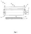
- FIG. 1a device 1 for scattering particles on a surface is shown in a schematic front view.
- the devicecomprises a container 20 for the particles to be scattered and a roller-like distribution element 30, which is arranged under the container 20.
- a means 32is arranged, with which the distribution element 30 can be set in the direction of its longitudinal axis in vibration or vibration (indicated by a double arrow).
- the means 32is in the case shown a mechanical vibration generator and preferably operates in a frequency range of ten to 250 hertz, more preferably from 20 to 150 hertz, and most preferably from 30 to 80 hertz.
- the distribution element 30is mounted swingably via fastening elements 34, as indicated by the double arrows.
- a conveyorwhich has conveyor rollers 42, by means of which a wood-based panel 44 (or an impregnated paper) can be passed under the device 1.
- the particles to be scatteredfall from the container 20 via the distribution element 30 on the surface 46 of the wood-based panels 44 and are thus evenly distributed on the surface 46 by the vibrations of the distribution element 30.
- the wood-based panel 44is, as in all embodiments described herein, preferably a laminate panel comprising a support plate made of MDF or HDF material and a decorative paper which is glued on the upper side 46 of the wood-based panel 44.
- the decorative paperis impregnated with a resin, such as an amino or melamine resin, and still wet at the time when it passes under the device 1.
- the scattered particlessink at least partially into the still moist resin impregnation and form with this after drying of the resin and subsequent pressing an extremely abrasion resistant surface.
- the inventionis equally well suited to sprinkle only the impregnated paper, which then, for example, on suitable roller under the device is performed.
- the deviceis suitable for sprinkling impregnates before they are further processed into laminates, for example.
- the device 1is shown in a side view.
- the rollers 42 of the conveyorare clearly visible.
- the arrow next to the wood-based panel 44indicates the direction of movement of the plate 44.
- the particles 12are also shown schematically as they fall from the container 20 via a curved surface 36 of the distribution element 30, or are conveyed down by the vibration of the distribution element 30.
- the container 20has a scattering opening 22 for discharging the particles 12. Further, the container 20 is arranged on a device 24, with which the container 20 can be moved vertically. In this way, the distance between the scattering opening 22 and the distribution element 30 can be reduced and increased. Of course, other means are conceivable here to adjust the distance from the surface of the distribution element.
- the distance between the scattering opening and the surface of the distributing elementis preferably-as in all embodiments according to the invention-adjusted such that no particles emerge from the scattering opening without a vibration of the distributing element. Only by the transmission of the vibrations from the distribution element to the bed of particles in the container, they are quasi shaken out of the opening.
- FIG. 2is further indicated that the surface of the distribution element 30 is provided with a coating 38.
- the coating 38consists of a vulcanized rubber coating.
- a baffle 14is provided, with which the path of the particles 12 can be influenced.
- the baffle plate 14is adjustably arranged according to the invention so as to be able to influence the scattering of the particles on the surface of the panel 44 and the air flow.
- the baffle with a vibrator 16provided with the one hand, the scattering of the particles can be further influenced and on the other hand adhesion of the particles 12 can be prevented on the surface of the baffle plate 14.
- the distribution element of the figuresis preferably a steel roller and has for example a length between one and three meters and a diameter between 80 and 300 millimeters.
- the scattering opening 22is for example a gap which is between one and three meters long and has a width of one to three millimeters. It should therefore be clear to those skilled in the art that the schematic illustrations are not to scale, but that certain details are greatly increased for the sake of clarity. This applies in particular to the scattering opening 22 and the illustrated particles 12.
- the particles to be scatteredare usually of the order of magnitude of a few micrometers, in particular if they are abrasion-resistant particles, such as corundum particles, for coating the surface of a laminate panel.
- FIG. 3an alternative distribution element 30 'is shown.
- the distribution element 30 'is cylindrical, but it has no round, but an approximately quarter-circular cross-section.
- the effective curved surface 36 'ie the surface which is in contact with the particles 12 to be scattered and which is responsible for the distribution of these particles, describes a circular arc with a center angle ⁇ (center angle) of about 100 ° shown. In this case, however, it must be ensured that no uncontrolled self-motion occurs due to the asymmetrical shape.
- FIG. 3is the spill of the vertical center line 31 of the distribution element offset a few degrees. In this way it is ensured that the particles 12 to be distributed fall substantially in the desired direction on the right in the figure.
Landscapes
- Coating Apparatus (AREA)
- Application Of Or Painting With Fluid Materials (AREA)
Description
Translated fromGermanDie vorliegende Erfindung betrifft eine Vorrichtung zum Aufstreuen von Partikel, insbesondere auf eine Oberfläche von Holzwerkstoffplatten oder Imprägnaten, sowie ein Verfahren zum Aufstreuen von Partikeln.The present invention relates to a device for scattering particles, in particular to a surface of wood-based panels or impregnates, and to a method for scattering particles.
Aus dem Stand der Technik sind eine Reihe von Verfahren bekannt, um Partikel auf Oberflächen zu streuen. Aus der
Obwohl diese Vorrichtung zufriedenstellend arbeitet, bietet sie dennoch Raum für Verbesserungen. Zum Einen ist es wünschenswert die Dosierung der Menge an abgegebenen Partikeln pro Zeiteinheit besser über die Breite steuern zu können. Außerdem kann die Gleichmäßigkeit der Streuung der Partikel auf die Oberfläche weiter verbessert werden. Ein großer Nachteil der vorbenannten Vorrichtung ist weiter, dass durch das Herausbürsten der abriebfesten Partikel von der Oberfläche bzw. aus den Aussparungen in der Stahlwalze dieselbe einem Verschleiß unterworfen ist, da die abriebfesten Partikel wesentlich härter sind als das Stahl der Stahlwalze. Aus diesem Grund müssen die Stahlwalzen nach Stand der Technik regelmäßig, etwa alle sechs Monate bei einem ununterbrochenen Betrieb, gewechselt werden. Hierdurch fallen zum Einen Kosten an, und zum Anderen verschlechtert sich die Qualität der Streuung gegen Ende der Lebenszeit der Stahlwalze.Although this device works satisfactorily, it still offers room for improvement. On the one hand, it is desirable to be able to better control the metering of the amount of particles delivered per unit time across the width. In addition, the uniformity of the scattering of the particles on the surface can be further improved. A major disadvantage of the aforementioned device is further that the brushing of the abrasion-resistant particles from the surface or from the recesses in the steel roller is subjected to the same wear, since the abrasion-resistant particles are much harder than the steel of the steel roller. For this reason, the steel rollers of the prior art must be changed regularly, about every six months in an uninterrupted operation. On the one hand, this incurs costs, and on the other hand, the quality of scattering deteriorates towards the end of the life of the steel roller.
Die oben beschriebene Vorrichtung dient zur Bestreuung der Oberfläche von Laminatpaneelen oder Imprägnaten und ähnlichem. Laminatpaneele bestehen üblicherweise aus einer vier bis acht Millimeter dicken Trägerplatte aus MDF- oder HDF-Werkstoff, auf dessen Oberseite ein mit einem Dekor bedrucktes und mit einem Harz imprägniertes Papier, ein sogenanntes Dekorpapier, unter Druck und Temperatur aufgebracht wird. An der Unterseite der Trägerplatte ist ein mit Harz imprägniertes Gegenzugpapier eingerichtet, dass einem Verzug der Trägerplatte durch das aufgebrachte Dekorpapier entgegenwirken soll. Auf dieses Dekorpapier muss eine abriebfeste Schicht bestehend aus kleinen Korundpartikeln (die in einer Harzmatrix eingebettet sind), die in einer Harzmatrix eingebettet sind, aufgebracht werden, um der Oberfläche die nötige Haltbarkeit zu verleihen. Ein weiterer Stand der Technik ist in Dokument
Ausgehend von diesem Stand der Technik stellt sich die Aufgabe, eine Vorrichtung zum Aufstreuen von Partikeln auf eine Oberfläche bereitzustellen, die die oben genannten Nachteile des Standes der Technik ausräumt bzw. vermindert. Insbesondere stellt sich die Aufgabe eine Vorrichtung bereit zu stellen, die eine gut dosierbare Streuung ermöglicht und einem geringerem Verschleiß unterworfen ist und daher kostengünstiger betrieben werden kann. Insbesondere ist es die Aufgabe der Erfindung einen Vorrichtung zum Aufstreuen von abriebfesten Partikeln auf die Oberfläche von Holzwerkstoffpaneelen, insbesondere von Laminatpaneelen, wie oben beschrieben, bereitzustellen.Starting from this prior art, the object is to provide a device for scattering particles on a surface, which eliminates or reduces the above-mentioned disadvantages of the prior art. In particular, the object is an apparatus to provide that allows a well-dosed dispersion and is subject to less wear and therefore can be operated more cost-effectively. In particular, it is the object of the invention to provide a device for sprinkling abrasion-resistant particles on the surface of wood-based panels, in particular of laminate panels, as described above.
Diese und andere Aufgaben, die beim Lesen der folgenden Beschreibung noch genannt werden oder vom Fachmann erkannt werden können, werden mit einer Vorrichtung nach Anspruch 1 sowie einem Verfahren nach Anspruch 13 gelöst.These and other objects which will become apparent upon reading the following description or which may be recognized by those skilled in the art are achieved by a device according to
Die erfindungsgemäße Vorrichtung zum Aufstreuen von abriebfesten Partikeln auf eine Oberfläche umfasst die Merkmale von Anspruch 1. In Ausführungsformen der Erfindung werden etwa Korundpartikeln, auf die Oberfläche von Holzwerkstoffpaneelen, Imprägnaten und ähnlichem, insbesondere Laminatpaneelen, aufgestreut und die Vorrichtung umfasst einen Behälter für die zu streuenden Partikel mit zumindest einer Streuöffnung zum Ausgeben von Partikeln sowie ein walzenartiges Verteilelement mit einer gekrümmten Oberfläche. Die Streuöffnung ist oberhalb der gekrümmten Oberfläche des Verteilelements angeordnet und erstreckt sich vorzugsweise parallel zur Längsachse des walzenartigen Verteilelements. Die Länge der Streuöffnung wird vorzugsweise ausgehend von der Größe der zu bestreuenden Oberfläche gewählt, dies gilt ebenso für die Länge des walzenartigen Verteilelements. Soll beispielsweise einen Oberfläche mit einer Breite von zwei Metern bestreut werden, so müssen walzenartiges Verteilelement und Streuöffnung ebenfalls zumindest etwa zwei Meter lang sein. In allen hierin beschriebenen Ausführungsformen ist die Streuöffnung vorzugsweise ein Spalt (Streuspalt).The device according to the invention for spreading abrasion-resistant particles onto a surface comprises the features of
Außerdem umfasst die Vorrichtung Mittel, mit denen das walzenartige Verteilelement in Längsrichtung in Vibration versetzt werden kann, so dass die Partikel aus der Streuöffnung über die gekrümmte Fläche hinweg nach unten in Richtung der zu bestreuenden Oberfläche fallen. Die Vibration des Verteilelements erfüllt dabei vorzugsweise mehrere Funktionen. Zum Einen sorgt sie für eine gleichmäßige Verteilung bzw. Streuung der Partikel auf die zu bestreuende Oberfläche. Zum Anderen entfällt durch die Vibration die Notwenigkeit das walzenartige Verteilelement zu drehen, sowie die Notwendigkeit einer Bürstenwalze, mit der im Stand der Technik die Partikel von der Oberfläche des Verteilelements gebürstet wurden. Überraschenderweise wurde festgestellt, dass durch die Vibration des Verteilelements kein oder kaum Verschleiß an der Oberfläche des Verteilelements auftritt. Daher können mit der Vorrichtung der Erfindung insbesondere abriebfeste Partikel, wie beispielsweise Korundpartikel besonders gut verarbeitet werden.In addition, the device comprises means with which the roller-like distribution element can be vibrated in the longitudinal direction, so that the particles fall from the scattering opening over the curved surface away in the direction of the surface to be spread. The vibration of the distribution element preferably fulfills several functions. On the one hand, it ensures even distribution or scattering of the particles on the surface to be spread. On the other hand eliminates by the vibration the need to rotate the roller-like distribution element, and the need for a brush roller with which in the prior art, the particles were brushed from the surface of the distribution element. Surprisingly, it has been found that no or little wear occurs on the surface of the distributor element due to the vibration of the distributor element. Therefore, abrasion-resistant particles, such as, for example, corundum particles, can be processed particularly well with the device of the invention.
Es sollte dem Fachmann klar sein, dass der Behälter für die zu streuenden Partikel weit zu verstehen ist und jegliche Art von Aufbewahrungsmöglichkeit umfasst, mit der zu streuende Partikel im Sinne der Erfindung bereit gestellt werden können. Wesentlich für die Erfindung ist vielmehr die Streuöffnung bzw. der Streuspalt und dessen Ausrichtung zum walzenartigen Verteilelement. Das walzenartige Verteilelement ist vorzugsweise eine Walze, und insbesondere eine Stahlwalze, da derartige Walzen einfach und relativ kostengünstig zu beschaffen sind. Es sollte dem Fachmann jedoch klar sein, das es bei der Erfindung im Wesentlichen auf die wirksame gekrümmte Oberfläche des Verteilelements ankommt, d. h. diejenige Oberfläche die in Berührung mit den zu streuenden Partikeln kommt und für die Streuwirkung der Partikel wirksam ist. Beispielsweise könnte das walzenartige Verteilelement daher auch aus einer Walze bestehen, die in Längsrichtung quasi "durchgeschnitten" ist, d. h. beispielsweise einen halbkreisförmigen, dreiviertelkreisförmigen oder viertelkreisförmigen Querschnitt hat.It should be clear to the person skilled in the art that the container for the particles to be scattered is to be understood widely and includes any type of storage possibility with which particles to be scattered can be provided in the sense of the invention. Essential for the invention is rather the scattering opening or the spreading gap and its orientation to the roller-like distribution element. The roller-like distribution element is preferably a roller, and in particular a steel roller, since such rollers are easy and relatively inexpensive to procure. However, it should be clear to those skilled in the art that in the invention, what matters is the effective curved surface of the distribution element, i. H. the surface which comes into contact with the particles to be scattered and is effective for the scattering effect of the particles. For example, the roller-like distribution element could therefore also consist of a roller which is quasi "cut through" in the longitudinal direction, i. H. for example, has a semicircular, three-quarter circular or quarter-circular cross-section.
Für eine besonders wirksame Streuung haben Untersuchungen des Anmelders ergeben, dass die Krümmungslinie der gekrümmten Oberfläche vorzugsweise ein Kreisbogen sein sollte. Dieser Kreisbogen sollte insbesondere einen Mittelpunktswinkel (auch Zentriwinkel genannt) von zumindest siebzig Grad, bevorzugt zumindest achtzig Grad, noch bevorzugter zumindest etwa neunzig Grad und am meisten bevorzugt zumindest etwa einhundert Grad haben.For a particularly effective scattering investigations of the applicant have shown that the curvature of the curved surface should preferably be a circular arc. In particular, this circular arc should have a center angle (also called center angle) of at least seventy degrees, preferably at least eighty degrees, more preferably at least about ninety degrees, and most preferably at least about one hundred degrees.
Erfindungsgemäß ist die gekrümmte Oberfläche des walzenartigen Verteilelements mit einer Beschichtung versehen. Diese Beschichtung ist ein Gummi, der in bekannter Weise auf die Oberfläche des Verteilelements aufgebracht ist, insbesondere aufvulkanisiert ist. Das Verteilelement ist vorzugsweise in allen hierin beschriebenen Ausführungsformen aus Stahl gefertigt. Der Anmelder hat überraschend festgestellt, dass eine Gummierung der Oberfläche des walzenartigen Verteilelements die Gleichmäßigkeit der Streuung der Partikel im Vergleich zu einer unbehandelten Stahloberfläche verbessert. Außerdem wurde festgestellt, dass die Gummierung erheblich bessere Verschleißeigenschaften im Vergleich zu einer reinen Stahloberfläche aufweist. Dies gilt insbesondere bei der Verwendung von abriebfesten Partikeln, wie beispielsweise Korundpartikel. Dies ist daher überraschend, weil die gummierte Oberfläche natürlicherweise eine erheblich geringere Härte als beispielsweise eine Stahloberfläche hat. Es wird vermutet, dass die Gummierung durch ihre elastische Nachgiebigkeit weniger anfällig gegenüber den scharfen Kanten der zu streuenden Partikel ist als die härtere, jedoch nicht nachgiebige Stahloberfläche.According to the invention, the curved surface of the roller-like distribution element is provided with a coating. This coating is a rubber which is applied in a known manner to the surface of the distribution element, in particular vulcanized. The distribution element is preferably made of steel in all the embodiments described herein. The Applicant has surprisingly found that a gumming of the surface the roller-like distribution element improves the uniformity of the scattering of the particles compared to an untreated steel surface. In addition, it has been found that the rubber coating has significantly better wear properties compared to a pure steel surface. This is especially true when using abrasion-resistant particles, such as corundum particles. This is therefore surprising because the rubberized surface naturally has a considerably lower hardness than, for example, a steel surface. It is believed that the elasticity of the gumming makes it less susceptible to the sharp edges of the particles to be scattered than the harder but non-compliant steel surface.
Wie bereits erwähnt ist die Vorrichtung besonders für die Verarbeitung von abriebbeständigen Partikeln, wie insbesondere Korundpartikeln, geeignet. Die oben beschriebene Gummierung oder Gummibeschichtung sollte vorzugsweise eine Shore-A Härte zwischen 40 und 80 Shore, bevorzugt 50 und 70 Shore und besonders bevorzugt zwischen 55 und 65 Shore aufweisen. Die Shore-Härte ist ein bekannter Werkstoffkennwert für Elastomere und Kunststoffe und in den Normen DIN 53505 und DIN 7868 festgelegt.As already mentioned, the device is particularly suitable for the processing of abrasion-resistant particles, in particular corundum particles. The gum or rubber coating described above should preferably have a Shore A hardness between 40 and 80 Shore, preferably 50 and 70 Shore, and more preferably between 55 and 65 Shore. The Shore hardness is a known material characteristic for elastomers and plastics and defined in the DIN 53505 and DIN 7868 standards.
Zur Erzeugung der Vibration des walzenartigen Verteilelements sind dem Fachmann verschiedene mechanische Schwingungserzeuger bekannt. Das Verteilelement ist vorzugsweise schwingbar gelagert und wird beispielsweise mit einem Vibrationsmittel oder Schwingungserzeuger in einem Frequenzbereich von 10 bis 250 Hertz, vorzugsweise 20 bis 150 Hertz und am meisten bevorzugt von 30 bis 80 Hertz angeregt. Die Schwingbewegung liegt im Bereich von einigen Zehntelmillimetern, wie etwa 0,1 mm. Es wurde festgestellt, dass diese Frequenzbereiche zu besonders guten Ergebnissen führen. Es sollte dem Fachmann klar sein, dass in allen hierin beschriebenen Ausführungsformen allgemein das walzenartige Verteilelement nicht um seine Längsachse rotiert werden muss, sondern vielmehr nicht rotierbar eingerichtet sein muss.To produce the vibration of the roller-like distribution element, various mechanical vibration generators are known to those skilled in the art. The distributing element is preferably swingably mounted and is excited, for example, by a vibrating means or vibrator in a frequency range of 10 to 250 hertz, preferably 20 to 150 hertz, and most preferably 30 to 80 hertz. The swinging motion is in the range of a few tenths of a millimeter, such as 0.1 mm. It has been found that these frequency ranges lead to particularly good results. It should be apparent to those skilled in the art that in all of the embodiments described herein, generally, the roller type distribution member does not must be rotated about its longitudinal axis, but rather must not be arranged rotatable.
Die Vorrichtung erlaubt eine besonders gute Einstellung der Mengenabgabe an ausgegebenen Partikeln. Bevorzugt ist in der Vorrichtung der Abstand zwischen dem Streuspalt bzw. der Streuöffnung und der gekrümmten Oberfläche des walzenartigen Verteilelements einstellbar, um die Menge an abgegebenen Partikel variieren zu können. Je größer der Abstand ist, umso mehr Partikel werden pro Zeiteinheit gefördert. Ebenso lässt sich die Menge an geförderten Partikeln durch die Einstellung der Vibration, bzw. der Frequenz beeinflussen. Daher sind die Mittel, um das Verteilelement in Vibration zu versetzen, vorzugsweise regelbar, um je nach Anwendungsfall eine geeignete Frequenz einstellen zu können. Die Vorrichtung ist besonders zur Verarbeitung von Partikeln mit einem Durchmesser von 60 bis 120 µm geeignet und besonders für Partikel mit Korngröße 220 bis 150.The device allows a particularly good adjustment of the quantity of spent particles. In the apparatus, the distance between the scattering gap or the scattering opening and the curved surface of the roller-like distribution element is preferably adjustable in order to be able to vary the amount of particles released. The larger the distance, the more particles are delivered per unit time. Likewise, the amount of particles conveyed can be influenced by adjusting the vibration or the frequency. Therefore, the means to put the distribution element in vibration, preferably adjustable to adjust depending on the application, a suitable frequency can. The device is particularly suitable for the processing of particles with a diameter of 60 to 120 microns and especially for particles with grain size 220 to 150.
Im Folgenden wird eine detaillierte Beschreibung der Figuren gegeben:
Figur 1Figur 2 ist eine schematische Seitenansicht derVorrichtung von Figur 1 undFigur 3 ist eine schematische Seitenansicht einer weiteren Ausführungsform der Erfindung.
FIG. 1 Fig. 10 is a schematic frontal view of a particle spreading apparatus according to the invention;FIG. 2 is a schematic side view of the device ofFIG. 1 andFIG. 3 is a schematic side view of another embodiment of the invention.
In
Die Holzwerkstoffplatte 44 ist, wie in allen hierin beschriebenen Ausführungsformen, vorzugsweise ein Laminatpaneel umfassend eine Trägerplatte aus MDF- oder HDF-Material sowie ein Dekorpapier, welches auf der Oberseite 46 der Holzwerkstoffplatte 44 aufgeklebt ist. Wie eingangs erläutert ist das Dekorpapier mit einem Harz, wie beispielsweise einem Amino-oder Melaminharz, getränkt und zum Zeitpunkt, wenn es unter der Vorrichtung 1 hindurchgeführt wird noch feucht. Die aufgestreuten Partikel sinken zumindest teilweise in die noch feuchte Harzimprägnierung ein und bilden mit dieser nach Austrocknung des Harzes und anschließender Verpressung eine extrem abriebfeste Oberfläche.The wood-based
Es sollte dem Fachmann jedoch klar sein, das die Erfindung ebenso gut geeignet ist, um nur das imprägnierte Papier zu bestreuen, das dann bspw. auf geeigneten Rollgängen unter der Vorrichtung durchgeführt wird. Mit anderen Worten: die Vorrichtung ist dazu geeignet Imprägnate zu bestreuen, bevor diese bspw. zu Laminaten weiter verarbeitet werden.However, it should be clear to those skilled in the art that the invention is equally well suited to sprinkle only the impregnated paper, which then, for example, on suitable roller under the device is performed. In other words, the device is suitable for sprinkling impregnates before they are further processed into laminates, for example.
In
In
Das Verteilelement der Figuren ist vorzugsweise eine Stahlwalze und hat beispielsweise eine Länge zwischen einem und drei Metern und einen Durchmesser zwischen 80 und 300 Millimetern. Die Streuöffnung 22 ist beispielsweise ein Spalt der zwischen einem und drei Metern lang ist und eine Breite von einem bis drei Millimetern hat. Es sollte dem Fachmann daher klar sein, dass die schematischen Darstellungen nicht maßstabsgetreu sind, sondern dass bestimmte Einzelheiten der Klarstellung halber stark vergrößert sind. Dies gilt insbesondere für die Streuöffnung 22 sowie die dargestellten Partikel 12. Die zu streuenden Partikel sind üblicherweise, insbesondere wenn es sich dabei um abriebfeste Partikel, wie etwa Korund-partikel, zur Bestreuung der Oberfläche eines Laminatpaneels handelt, in der Größenordnung von einigen Mikrometern.The distribution element of the figures is preferably a steel roller and has for example a length between one and three meters and a diameter between 80 and 300 millimeters. The
In
Claims (13)
- Device (1) to disperse particles (12) onto a surface (46), in particular onto a surface of wood material panels or impregnates, comprising
a container (20) for the particles to be dispersed with at least one scatter opening (22) to dispend articles, and
a roller like distributing element (30) with a curved surface (36), wherein the scatter opening is arranged above the curved surface,characterized in that the curved surface (36) of the roller like distributing element (30) is rubberized and that means (32) are provided, by means of which the roller like distributing element can be brought into vibration in longitudinal direction, such that particles (12) fall out of the scatter opening (22) via the curved surface (36) downwards in the direction of the surface to be sprinkled andin that the device (1) comprises at least one baffle plate (14), which is adjustable to influence the scattering of the particles onto the surface and the air current. - Device according to claim 1,characterized in that the line of curvature of the curved surface (36) is a circular arc and in particular with a central angle α of at least 70°, preferably at least 80° and most preferred at least approximately 90°.
- Device according to any one of claims 1 or 2,characterized in that the roller like distributing element (30) is a roller and the scatter opening (22) is a scatter slot, which is arranged parallel to the longitudinal axis of the roller.
- Device according to any of the preceding claims,characterized in that the particles (12) comprise abrasion resistant particles and preferably corundum particles.
- Device according to any of the preceding claims,characterized in that the scatter opening (22) is formed such that particles (12) can fall out of the scatter opening downwardly due to gravity and that between scatter opening and the curved surface (36) of the roller like distributing element (30) a distance is provided, which is chosen small enough, such that without any vibration of the roller like distributing element, no particles will fall out of the scatter opening.
- Device according to any of the preceding claims,characterized in that the roller like distributing element (30) is a steel roller with a length between 1 and 3 meters and a diameter between 80 and 300 mm andin that the scatter opening (22) is a scatter slot, which is between 1 and 13 meters long and has a width of between 1 and 3 mm.
- Device according to any of the preceding claims,characterized in that the roller like distributing element (30) is a steel roller and the scatter opening (22) is a scatter slot, which is arranged parallel to the longitudinal axis of the roller and which is offset by 1 to 30° angular degree from the vertical centre line (31) of the steel roller, preferably 3 to 20° and most preferably 5 to 15°.
- Device according to any of the preceding claims,characterized in that the distance between scatter opening (22) and curved surface (36) of the roller like distributing element (30) is adjustable - preferably over the whole width independently - to vary the amount of dispersed particles.
- Device according to any of the preceding claims,characterized in that the means (32) to bring the roller like distributing element into vibration works in a frequency range of 10 to 250 Hz, preferably 20 to 150 Hz and most preferably of 30 to 80 Hz.
- Device according to any of the preceding claims,characterized in that the roller like distributing element (30) is not rotateable around its longitudinal axis.
- Device according to claim 1,characterized in that further means (16; 32) are provided, to bring the baffle plate into vibration.
- Device according to any one of claims 1 or 11,characterized in that the baffle plate (14) is connected with the roller like distributing element (30), such that the vibration can be transferred from the roller like distributing element to the baffle plate(s).
- Method to disperse articles on a surface, in particular onto a surface of wood material panels and impregnates, comprising the following steps:- providing a device according to any one of claims 1 to 12;- providing of particles in the container;- vibrating the roller like distributing element in a longitudinal direction, to convey particles out of the scatter opening; whereby- the roller like distributing element (3) is not rotated around its longitudinal axle.
Priority Applications (6)
| Application Number | Priority Date | Filing Date | Title |
|---|---|---|---|
| DK08017203.4TDK2168690T3 (en) | 2008-09-30 | 2008-09-30 | Corundum spreads |
| PL08017203TPL2168690T3 (en) | 2008-09-30 | 2008-09-30 | Korund distributor |
| EP08017203AEP2168690B1 (en) | 2008-09-30 | 2008-09-30 | Korund distributor |
| US12/566,068US9908141B2 (en) | 2008-09-30 | 2009-09-24 | Device to disperse particles onto a surface |
| CN200910174556.1ACN101712166B (en) | 2008-09-30 | 2009-09-28 | For by distribution of particles to the equipment on surface |
| RU2009135713/05ARU2513836C2 (en) | 2008-09-30 | 2009-09-28 | Method of particles distribution over surface and device to this end |
Applications Claiming Priority (1)
| Application Number | Priority Date | Filing Date | Title |
|---|---|---|---|
| EP08017203AEP2168690B1 (en) | 2008-09-30 | 2008-09-30 | Korund distributor |
Publications (2)
| Publication Number | Publication Date |
|---|---|
| EP2168690A1 EP2168690A1 (en) | 2010-03-31 |
| EP2168690B1true EP2168690B1 (en) | 2012-11-07 |
Family
ID=40351992
Family Applications (1)
| Application Number | Title | Priority Date | Filing Date |
|---|---|---|---|
| EP08017203AActiveEP2168690B1 (en) | 2008-09-30 | 2008-09-30 | Korund distributor |
Country Status (6)
| Country | Link |
|---|---|
| US (1) | US9908141B2 (en) |
| EP (1) | EP2168690B1 (en) |
| CN (1) | CN101712166B (en) |
| DK (1) | DK2168690T3 (en) |
| PL (1) | PL2168690T3 (en) |
| RU (1) | RU2513836C2 (en) |
Families Citing this family (11)
| Publication number | Priority date | Publication date | Assignee | Title |
|---|---|---|---|---|
| CH704729B1 (en)* | 2011-03-22 | 2025-07-15 | Reishauer Ag | Method and device for producing a base body with hard material particles. |
| CN104631744B (en)* | 2014-12-13 | 2016-11-02 | 田芳 | A kind of crystal pearl decoration soft material process units |
| EP3390062A4 (en)* | 2015-12-18 | 2019-08-07 | 3M Innovative Properties Company | METHOD FOR DEPOSITION OF DRY POWDER PARTICLES ON A SUBSTRATE AND FOR FIXING PARTICLES BY BONDING ON THE SUBSTRATE |
| WO2017106098A1 (en)* | 2015-12-18 | 2017-06-22 | 3M Innovative Properties Company | Process for depositing dry powder particles onto a substrate and attaching the particles to the substrate |
| PT3246175T (en) | 2016-05-20 | 2018-10-22 | Flooring Technologies Ltd | Method of producing an abrasion resistant wooden panel and production line for same |
| CN106540868B (en)* | 2016-12-12 | 2022-11-22 | 江西中材太阳能新材料有限公司 | Automatic sand planting equipment and automatic sand planting system |
| PT3686028T (en) | 2019-01-22 | 2021-05-05 | Flooring Technologies Ltd | Method for manufacturing an abrasion-resistant wooden panel |
| ES2916708T3 (en) | 2019-01-23 | 2022-07-05 | Flooring Technologies Ltd | Procedure for the manufacture of a multilayer panel resistant to abrasion and water |
| JP7503753B2 (en)* | 2020-05-11 | 2024-06-21 | パナソニックIpマネジメント株式会社 | Powder coating apparatus and method for manufacturing energy device |
| CN113911795B (en)* | 2021-12-14 | 2022-03-18 | 江苏靓时新材料科技股份有限公司 | Decorative paper detects conveyor |
| DE102021006409A1 (en) | 2021-12-29 | 2023-06-29 | Paul Hartmann Ag | Method of dosing and applying a small amount of a particulate material |
Family Cites Families (17)
| Publication number | Priority date | Publication date | Assignee | Title |
|---|---|---|---|---|
| DE608898C (en)* | 1931-06-05 | 1935-02-02 | Merritt Engineering & Sales Co | Covering surfaces with powdery material |
| US2594348A (en)* | 1947-01-18 | 1952-04-29 | Dayton Rubber Company | Rubber covered roll |
| US2737319A (en)* | 1952-12-16 | 1956-03-06 | Western Electric Co | Apparatus for feeding granular materials |
| US2897577A (en)* | 1954-05-12 | 1959-08-04 | Grove Silk Company | Method of dulling nylon and like materials |
| AT325005B (en) | 1967-11-20 | 1975-09-25 | Benno Saladin | PROCESS AND DEVICE FOR COATING IN ENDLESS TRAILS OR IN FORMAT CUT DOCUMENTS WITH POWDERED MATERIALS |
| US3740062A (en)* | 1971-08-13 | 1973-06-19 | Mccord Corp | Adhesive in capsule coated gasket |
| DE2939828C2 (en)* | 1979-10-01 | 1984-05-10 | Saladin AG, Sirnach, Thurgau | Method and device for coating a surface with a powder |
| US4245581A (en)* | 1979-11-16 | 1981-01-20 | The Pillsbury Company | Parsley applicator |
| JPS58142367A (en)* | 1982-02-17 | 1983-08-24 | Konishiroku Photo Ind Co Ltd | Roll cleaner |
| SE460274B (en)* | 1988-02-18 | 1989-09-25 | Perstorp Ab | PROCEDURES FOR PREPARING A RESISTANT, DECORATIVE TEMPORARY LAMINATE |
| US5365815A (en)* | 1993-01-12 | 1994-11-22 | Pfaff Jr Alan R | Rotary scrap stripper |
| SE509109C2 (en)* | 1997-04-21 | 1998-12-07 | Perstorp Ab | Process for the production of abrasion resistant thermosetting laminates |
| DE19817805A1 (en)* | 1998-04-21 | 1999-10-28 | Gedib Ingbuero Innovation | Hardening bonding layer production process for bonding layer with pull-off surface layer |
| US6610147B2 (en) | 2001-08-31 | 2003-08-26 | Owens-Corning Fiberglas Technology, Inc. | Shingle granule valve and method of depositing granules onto a moving substrate |
| US6833014B2 (en)* | 2002-07-26 | 2004-12-21 | 3M Innovative Properties Company | Abrasive product, method of making and using the same, and apparatus for making the same |
| CN1860187B (en) | 2003-09-30 | 2011-04-20 | 克诺普拉斯技术股份公司 | Adhesive-coated corundum-sprayed decorative paper |
| RU2329874C2 (en)* | 2006-07-07 | 2008-07-27 | Открытое акционерное общество "Гомельобои" | Device for application of powder onto material cloth |
- 2008
- 2008-09-30PLPL08017203Tpatent/PL2168690T3/enunknown
- 2008-09-30EPEP08017203Apatent/EP2168690B1/enactiveActive
- 2008-09-30DKDK08017203.4Tpatent/DK2168690T3/enactive
- 2009
- 2009-09-24USUS12/566,068patent/US9908141B2/enactiveActive
- 2009-09-28RURU2009135713/05Apatent/RU2513836C2/enactive
- 2009-09-28CNCN200910174556.1Apatent/CN101712166B/enactiveActive
Also Published As
| Publication number | Publication date |
|---|---|
| US9908141B2 (en) | 2018-03-06 |
| US20100080896A1 (en) | 2010-04-01 |
| PL2168690T3 (en) | 2013-03-29 |
| RU2513836C2 (en) | 2014-04-20 |
| CN101712166A (en) | 2010-05-26 |
| DK2168690T3 (en) | 2013-02-11 |
| EP2168690A1 (en) | 2010-03-31 |
| RU2009135713A (en) | 2011-04-10 |
| CN101712166B (en) | 2015-11-25 |
Similar Documents
| Publication | Publication Date | Title |
|---|---|---|
| EP2168690B1 (en) | Korund distributor | |
| DE10117807B4 (en) | Scattering device and method for applying solid particles | |
| DE69824865T2 (en) | DEVICE FOR DISTRIBUTING PARTICLES ON PAPER AND METHOD FOR PRODUCING PAPER WITH PARTICLES | |
| EP2090695B1 (en) | Method for producing a scour-proof overlay | |
| EP3458281B1 (en) | Production line for producing an abrasion-resistant wood material panel | |
| DE102007049947A1 (en) | Three-layer grit mat manufacturing method for manufacturing oriented strand board chip board, involves providing dividing device below breaking device for dividing falling chipping to transverse and longitudinal orientation devices | |
| EP1020560B1 (en) | Process and apparatus for impregnating and coating paper | |
| DE202016101306U1 (en) | Production of a decorated wall or floor panel | |
| DE102005060754A1 (en) | Method and installation for applying solid particles to a substrate | |
| DE1504835B1 (en) | Method and device for applying cover layers to carrier plates made of rigid plastic foam | |
| EP1088595B1 (en) | Device for applying an abrasive substance onto a moving web | |
| EP1256426B1 (en) | Device for spreading particles, in particular wooden chips, wooden fibers or the like on a coveyor belt | |
| DE102009054807A1 (en) | Method and scattering head for producing a grit mat from at least one oriented scattered layer in the course of the production of wood-based panels | |
| DE10122972B4 (en) | Grit plant for scattering of grit, in particular of wood fibers, wood chips, o. The like. On a Streubandförderer | |
| DE102006030122B4 (en) | The scattering material plant | |
| DE69835772T2 (en) | DEVICE FOR SPREADING AND DISTRIBUTING PARTICLES ON A MATERIAL STRIP | |
| DE102014101424B3 (en) | Device for sprinkling free-flowing material | |
| DE19846106A1 (en) | Spreading station | |
| EP1442855B1 (en) | Device for distributing granular material onto a continously travelling support | |
| DE3615357A1 (en) | METHOD AND DEVICE FOR FORMING A TRAIN | |
| DE102007029578B4 (en) | powder coater | |
| DE3811677A1 (en) | DEVICE FOR COMPARISONING THE AREA WEIGHT DISTRIBUTION OF FLEECE | |
| DE102017111009B3 (en) | dispersion unit | |
| DE102017111018B4 (en) | dispersion unit | |
| EP4094848B1 (en) | Process for manufacturing an abrasion-resistant laminate |
Legal Events
| Date | Code | Title | Description |
|---|---|---|---|
| PUAI | Public reference made under article 153(3) epc to a published international application that has entered the european phase | Free format text:ORIGINAL CODE: 0009012 | |
| AK | Designated contracting states | Kind code of ref document:A1 Designated state(s):AT BE BG CH CY CZ DE DK EE ES FI FR GB GR HR HU IE IS IT LI LT LU LV MC MT NL NO PL PT RO SE SI SK TR | |
| AX | Request for extension of the european patent | Extension state:AL BA MK RS | |
| 17P | Request for examination filed | Effective date:20100611 | |
| AKX | Designation fees paid | Designated state(s):AT BE BG CH CY CZ DE DK EE ES FI FR GB GR HR HU IE IS IT LI LT LU LV MC MT NL NO PL PT RO SE SI SK TR | |
| 17Q | First examination report despatched | Effective date:20110307 | |
| GRAP | Despatch of communication of intention to grant a patent | Free format text:ORIGINAL CODE: EPIDOSNIGR1 | |
| GRAS | Grant fee paid | Free format text:ORIGINAL CODE: EPIDOSNIGR3 | |
| GRAA | (expected) grant | Free format text:ORIGINAL CODE: 0009210 | |
| AK | Designated contracting states | Kind code of ref document:B1 Designated state(s):AT BE BG CH CY CZ DE DK EE ES FI FR GB GR HR HU IE IS IT LI LT LU LV MC MT NL NO PL PT RO SE SI SK TR | |
| REG | Reference to a national code | Ref country code:GB Ref legal event code:FG4D Free format text:NOT ENGLISH | |
| REG | Reference to a national code | Ref country code:CH Ref legal event code:EP Ref country code:AT Ref legal event code:REF Ref document number:582764 Country of ref document:AT Kind code of ref document:T Effective date:20121115 | |
| REG | Reference to a national code | Ref country code:IE Ref legal event code:FG4D Free format text:LANGUAGE OF EP DOCUMENT: GERMAN | |
| REG | Reference to a national code | Ref country code:SE Ref legal event code:TRGR | |
| REG | Reference to a national code | Ref country code:DE Ref legal event code:R096 Ref document number:502008008594 Country of ref document:DE Effective date:20130103 | |
| REG | Reference to a national code | Ref country code:RO Ref legal event code:EPE | |
| REG | Reference to a national code | Ref country code:DK Ref legal event code:T3 | |
| REG | Reference to a national code | Ref country code:CH Ref legal event code:NV Representative=s name:HEPP WENGER RYFFEL AG, CH | |
| REG | Reference to a national code | Ref country code:NO Ref legal event code:T2 Effective date:20121107 | |
| REG | Reference to a national code | Ref country code:PL Ref legal event code:T3 | |
| REG | Reference to a national code | Ref country code:NL Ref legal event code:VDEP Effective date:20121107 | |
| REG | Reference to a national code | Ref country code:LT Ref legal event code:MG4D | |
| PG25 | Lapsed in a contracting state [announced via postgrant information from national office to epo] | Ref country code:FI Free format text:LAPSE BECAUSE OF FAILURE TO SUBMIT A TRANSLATION OF THE DESCRIPTION OR TO PAY THE FEE WITHIN THE PRESCRIBED TIME-LIMIT Effective date:20121107 Ref country code:HR Free format text:LAPSE BECAUSE OF FAILURE TO SUBMIT A TRANSLATION OF THE DESCRIPTION OR TO PAY THE FEE WITHIN THE PRESCRIBED TIME-LIMIT Effective date:20121107 Ref country code:NL Free format text:LAPSE BECAUSE OF FAILURE TO SUBMIT A TRANSLATION OF THE DESCRIPTION OR TO PAY THE FEE WITHIN THE PRESCRIBED TIME-LIMIT Effective date:20121107 Ref country code:LT Free format text:LAPSE BECAUSE OF FAILURE TO SUBMIT A TRANSLATION OF THE DESCRIPTION OR TO PAY THE FEE WITHIN THE PRESCRIBED TIME-LIMIT Effective date:20121107 Ref country code:IS Free format text:LAPSE BECAUSE OF FAILURE TO SUBMIT A TRANSLATION OF THE DESCRIPTION OR TO PAY THE FEE WITHIN THE PRESCRIBED TIME-LIMIT Effective date:20130307 | |
| PG25 | Lapsed in a contracting state [announced via postgrant information from national office to epo] | Ref country code:SI Free format text:LAPSE BECAUSE OF FAILURE TO SUBMIT A TRANSLATION OF THE DESCRIPTION OR TO PAY THE FEE WITHIN THE PRESCRIBED TIME-LIMIT Effective date:20121107 Ref country code:PT Free format text:LAPSE BECAUSE OF FAILURE TO SUBMIT A TRANSLATION OF THE DESCRIPTION OR TO PAY THE FEE WITHIN THE PRESCRIBED TIME-LIMIT Effective date:20130307 Ref country code:GR Free format text:LAPSE BECAUSE OF FAILURE TO SUBMIT A TRANSLATION OF THE DESCRIPTION OR TO PAY THE FEE WITHIN THE PRESCRIBED TIME-LIMIT Effective date:20130208 Ref country code:LV Free format text:LAPSE BECAUSE OF FAILURE TO SUBMIT A TRANSLATION OF THE DESCRIPTION OR TO PAY THE FEE WITHIN THE PRESCRIBED TIME-LIMIT Effective date:20121107 | |
| PG25 | Lapsed in a contracting state [announced via postgrant information from national office to epo] | Ref country code:BG Free format text:LAPSE BECAUSE OF FAILURE TO SUBMIT A TRANSLATION OF THE DESCRIPTION OR TO PAY THE FEE WITHIN THE PRESCRIBED TIME-LIMIT Effective date:20130207 Ref country code:EE Free format text:LAPSE BECAUSE OF FAILURE TO SUBMIT A TRANSLATION OF THE DESCRIPTION OR TO PAY THE FEE WITHIN THE PRESCRIBED TIME-LIMIT Effective date:20121107 Ref country code:SK Free format text:LAPSE BECAUSE OF FAILURE TO SUBMIT A TRANSLATION OF THE DESCRIPTION OR TO PAY THE FEE WITHIN THE PRESCRIBED TIME-LIMIT Effective date:20121107 | |
| PG25 | Lapsed in a contracting state [announced via postgrant information from national office to epo] | Ref country code:IT Free format text:LAPSE BECAUSE OF FAILURE TO SUBMIT A TRANSLATION OF THE DESCRIPTION OR TO PAY THE FEE WITHIN THE PRESCRIBED TIME-LIMIT Effective date:20121107 | |
| PLBE | No opposition filed within time limit | Free format text:ORIGINAL CODE: 0009261 | |
| STAA | Information on the status of an ep patent application or granted ep patent | Free format text:STATUS: NO OPPOSITION FILED WITHIN TIME LIMIT | |
| 26N | No opposition filed | Effective date:20130808 | |
| PG25 | Lapsed in a contracting state [announced via postgrant information from national office to epo] | Ref country code:ES Free format text:LAPSE BECAUSE OF FAILURE TO SUBMIT A TRANSLATION OF THE DESCRIPTION OR TO PAY THE FEE WITHIN THE PRESCRIBED TIME-LIMIT Effective date:20130218 | |
| PG25 | Lapsed in a contracting state [announced via postgrant information from national office to epo] | Ref country code:CY Free format text:LAPSE BECAUSE OF FAILURE TO SUBMIT A TRANSLATION OF THE DESCRIPTION OR TO PAY THE FEE WITHIN THE PRESCRIBED TIME-LIMIT Effective date:20121107 | |
| REG | Reference to a national code | Ref country code:DE Ref legal event code:R097 Ref document number:502008008594 Country of ref document:DE Effective date:20130808 | |
| PG25 | Lapsed in a contracting state [announced via postgrant information from national office to epo] | Ref country code:MC Free format text:LAPSE BECAUSE OF FAILURE TO SUBMIT A TRANSLATION OF THE DESCRIPTION OR TO PAY THE FEE WITHIN THE PRESCRIBED TIME-LIMIT Effective date:20121107 | |
| GBPC | Gb: european patent ceased through non-payment of renewal fee | Effective date:20130930 | |
| REG | Reference to a national code | Ref country code:IE Ref legal event code:MM4A | |
| PG25 | Lapsed in a contracting state [announced via postgrant information from national office to epo] | Ref country code:GB Free format text:LAPSE BECAUSE OF NON-PAYMENT OF DUE FEES Effective date:20130930 Ref country code:IE Free format text:LAPSE BECAUSE OF NON-PAYMENT OF DUE FEES Effective date:20130930 | |
| PG25 | Lapsed in a contracting state [announced via postgrant information from national office to epo] | Ref country code:MT Free format text:LAPSE BECAUSE OF FAILURE TO SUBMIT A TRANSLATION OF THE DESCRIPTION OR TO PAY THE FEE WITHIN THE PRESCRIBED TIME-LIMIT Effective date:20121107 | |
| PG25 | Lapsed in a contracting state [announced via postgrant information from national office to epo] | Ref country code:HU Free format text:LAPSE BECAUSE OF FAILURE TO SUBMIT A TRANSLATION OF THE DESCRIPTION OR TO PAY THE FEE WITHIN THE PRESCRIBED TIME-LIMIT; INVALID AB INITIO Effective date:20080930 Ref country code:LU Free format text:LAPSE BECAUSE OF NON-PAYMENT OF DUE FEES Effective date:20130930 | |
| REG | Reference to a national code | Ref country code:FR Ref legal event code:PLFP Year of fee payment:9 | |
| REG | Reference to a national code | Ref country code:FR Ref legal event code:PLFP Year of fee payment:10 | |
| REG | Reference to a national code | Ref country code:FR Ref legal event code:PLFP Year of fee payment:11 | |
| REG | Reference to a national code | Ref country code:DE Ref legal event code:R082 Ref document number:502008008594 Country of ref document:DE Representative=s name:BARDEHLE PAGENBERG PARTNERSCHAFT MBB PATENTANW, DE Ref country code:DE Ref legal event code:R081 Ref document number:502008008594 Country of ref document:DE Owner name:XYLO TECHNOLOGIES AG, CH Free format text:FORMER OWNER: KRONOPLUS TECHNICAL AG, NIEDERTEUFEN, CH | |
| REG | Reference to a national code | Ref country code:NO Ref legal event code:CHAD Owner name:XYLO TECHNOLOGIES AG, CH | |
| REG | Reference to a national code | Ref country code:CH Ref legal event code:PFA Owner name:XYLO TECHNOLOGIES AG, CH Free format text:FORMER OWNER: KRONOPLUS TECHNICAL AG, CH | |
| REG | Reference to a national code | Ref country code:BE Ref legal event code:HC Owner name:XYLO TECHNOLOGIES AG; CH Free format text:DETAILS ASSIGNMENT: CHANGE OF OWNER(S), CHANGEMENT DE NOM DU PROPRIETAIRE; FORMER OWNER NAME: KRONOPLUS TECHNICAL AG Effective date:20181029 | |
| REG | Reference to a national code | Ref country code:AT Ref legal event code:HC Ref document number:582764 Country of ref document:AT Kind code of ref document:T Owner name:XYLO TECHNOLOGIES AG, CH Effective date:20190129 | |
| REG | Reference to a national code | Ref country code:DE Ref legal event code:R081 Ref document number:502008008594 Country of ref document:DE Owner name:LIGNUM TECHNOLOGIES AG, CH Free format text:FORMER OWNER: XYLO TECHNOLOGIES AG, TEUFEN, CH | |
| REG | Reference to a national code | Ref country code:BE Ref legal event code:HC Owner name:LIGNUM TECHNOLOGIES AG; CH Free format text:DETAILS ASSIGNMENT: CHANGE OF OWNER(S), CHANGE OF OWNER(S) NAME; FORMER OWNER NAME: KRONOPLUS TECHNICAL AG Effective date:20231113 | |
| REG | Reference to a national code | Ref country code:NO Ref legal event code:CHAD Owner name:LIGNUM TECHNOLOGIES AG, CH | |
| REG | Reference to a national code | Ref country code:AT Ref legal event code:HC Ref document number:582764 Country of ref document:AT Kind code of ref document:T Owner name:LIGNUM TECHNOLOGIES AG, CH Effective date:20240206 | |
| PGFP | Annual fee paid to national office [announced via postgrant information from national office to epo] | Ref country code:DE Payment date:20240918 Year of fee payment:17 | |
| PGFP | Annual fee paid to national office [announced via postgrant information from national office to epo] | Ref country code:DK Payment date:20240923 Year of fee payment:17 | |
| PGFP | Annual fee paid to national office [announced via postgrant information from national office to epo] | Ref country code:BE Payment date:20240918 Year of fee payment:17 | |
| PGFP | Annual fee paid to national office [announced via postgrant information from national office to epo] | Ref country code:FR Payment date:20240925 Year of fee payment:17 | |
| PGFP | Annual fee paid to national office [announced via postgrant information from national office to epo] | Ref country code:CZ Payment date:20240923 Year of fee payment:17 | |
| PGFP | Annual fee paid to national office [announced via postgrant information from national office to epo] | Ref country code:AT Payment date:20240919 Year of fee payment:17 | |
| PGFP | Annual fee paid to national office [announced via postgrant information from national office to epo] | Ref country code:PL Payment date:20240920 Year of fee payment:17 | |
| PGFP | Annual fee paid to national office [announced via postgrant information from national office to epo] | Ref country code:RO Payment date:20240924 Year of fee payment:17 Ref country code:NO Payment date:20240923 Year of fee payment:17 Ref country code:SE Payment date:20240919 Year of fee payment:17 | |
| PGFP | Annual fee paid to national office [announced via postgrant information from national office to epo] | Ref country code:TR Payment date:20240923 Year of fee payment:17 | |
| PGFP | Annual fee paid to national office [announced via postgrant information from national office to epo] | Ref country code:CH Payment date:20241001 Year of fee payment:17 |