EP2168546B1 - Mobile laminar flow hood for use in podiatry - Google Patents
Mobile laminar flow hood for use in podiatryDownload PDFInfo
- Publication number
- EP2168546B1 EP2168546B1EP08425636.1AEP08425636AEP2168546B1EP 2168546 B1EP2168546 B1EP 2168546B1EP 08425636 AEP08425636 AEP 08425636AEP 2168546 B1EP2168546 B1EP 2168546B1
- Authority
- EP
- European Patent Office
- Prior art keywords
- hood
- suctioning
- blowing
- blowing hood
- laminar
- Prior art date
- Legal status (The legal status is an assumption and is not a legal conclusion. Google has not performed a legal analysis and makes no representation as to the accuracy of the status listed.)
- Active
Links
- 238000007664blowingMethods0.000claimsdescription50
- 238000011282treatmentMethods0.000claimsdescription8
- 230000008878couplingEffects0.000claimsdescription4
- 238000010168coupling processMethods0.000claimsdescription4
- 238000005859coupling reactionMethods0.000claimsdescription4
- 238000011045prefiltrationMethods0.000claimsdescription4
- 238000011144upstream manufacturingMethods0.000claimsdescription4
- 230000002070germicidal effectEffects0.000claimsdescription3
- 239000002245particleSubstances0.000claimsdescription3
- 238000004891communicationMethods0.000claimsdescription2
- 230000036512infertilityEffects0.000description9
- 230000009471actionEffects0.000description5
- 230000008901benefitEffects0.000description3
- 239000000843powderSubstances0.000description3
- 239000003795chemical substances by applicationSubstances0.000description2
- 239000006185dispersionSubstances0.000description2
- 238000002682general surgeryMethods0.000description2
- 238000000034methodMethods0.000description2
- 238000001471micro-filtrationMethods0.000description2
- 206010052748Bacterial allergyDiseases0.000description1
- 208000035143Bacterial infectionDiseases0.000description1
- 230000002009allergenic effectEffects0.000description1
- 230000007815allergyEffects0.000description1
- 238000004873anchoringMethods0.000description1
- 230000005875antibody responseEffects0.000description1
- 230000001580bacterial effectEffects0.000description1
- 208000022362bacterial infectious diseaseDiseases0.000description1
- 238000006243chemical reactionMethods0.000description1
- 238000011109contaminationMethods0.000description1
- 238000012864cross contaminationMethods0.000description1
- 238000009792diffusion processMethods0.000description1
- 230000007613environmental effectEffects0.000description1
- 210000002615epidermisAnatomy0.000description1
- 238000001914filtrationMethods0.000description1
- 239000012530fluidSubstances0.000description1
- 239000012634fragmentSubstances0.000description1
- 230000036541healthEffects0.000description1
- 230000007246mechanismEffects0.000description1
- 238000012986modificationMethods0.000description1
- 230000004048modificationEffects0.000description1
- 230000000630rising effectEffects0.000description1
- 238000000926separation methodMethods0.000description1
- 210000001519tissueAnatomy0.000description1
Images


Classifications
- A—HUMAN NECESSITIES
- A61—MEDICAL OR VETERINARY SCIENCE; HYGIENE
- A61G—TRANSPORT, PERSONAL CONVEYANCES, OR ACCOMMODATION SPECIALLY ADAPTED FOR PATIENTS OR DISABLED PERSONS; OPERATING TABLES OR CHAIRS; CHAIRS FOR DENTISTRY; FUNERAL DEVICES
- A61G13/00—Operating tables; Auxiliary appliances therefor
- A61G13/10—Parts, details or accessories
- A61G13/108—Means providing sterile air at a surgical operation table or area
- A—HUMAN NECESSITIES
- A61—MEDICAL OR VETERINARY SCIENCE; HYGIENE
- A61G—TRANSPORT, PERSONAL CONVEYANCES, OR ACCOMMODATION SPECIALLY ADAPTED FOR PATIENTS OR DISABLED PERSONS; OPERATING TABLES OR CHAIRS; CHAIRS FOR DENTISTRY; FUNERAL DEVICES
- A61G15/00—Operating chairs; Dental chairs; Accessories specially adapted therefor, e.g. work stands
- A61G15/10—Parts, details or accessories
Definitions
- the present inventionrelates to a mobile laminar flow hood specifically devised for use in podiatry, and to a podiatric apparatus to which such hood is associated.
- the hood of the inventionis a hood adapted to generate a laminar flow of sterile air.
- blowing hoodsare known which are adapted to achieve a high degree of sterility in an operative area of a reduced extension.
- Such known hoodssuck air from the environment, microfiltrate the same, and blow it in the form of a laminar flow onto the operative area.
- Such an hoodis known from WO 00/04976 .
- HEPA-type filtersHigh Efficiency Particulate Air
- a typically required efficiency for these filtersis above 99.99% for particles having a diameter up to 0.3 ⁇ m. This high filtering power essentially eliminates all the contaminating agents from the air flow.
- the laminar flow generated by the blowing hoodconsists in a series of mutually parallel fluid layers, all of which have the same speed.
- the typical speeds of such flowsare approximately in the range of 0.5 m/s.
- the laminar flowdue to the absence of vortexes, keeps a high separation between what is immersed in the flow and what is outside it.
- hoodsallow a high protection both of the operative area directly hit by the flow, and also of the operator standing outside it. In fact, cross-contaminations and environmental contaminations are avoided by such hoods.
- sterile cabinetsare intended to be fixedly positioned inside the laboratory. They cannot be easily transported, and allow operating only on samples having predefined dimensions, in particular on samples which can be entirely introduced into the same cabinet.
- small organic residues in the form of powdersare generated during operation, which are then dispersed into the environment, together with the relative bacterial charge.
- a laminar flow hood as those described abovetends to promote the dispersion thereof, since the air flow removes the powders from the operative zone.
- object of the present inventionis to provide an apparatus having such characteristics as to meet the needs set forth above, and which have not been met by the prior art.
- a task of the present inventionis to provide an apparatus which allows operating on patients with a high sterility degree, therefore with the proper safety, while not dispersing organic residues into the surrounding environment.
- Another task of the present inventionis to provide an apparatus capable of creating a sterile operative area which can be readily prearranged from time to time in the more suitable position for that specific need.
- Figure 1represents a side top view of an embodiment of the apparatus according to the invention
- Figure 2arepresents a front, schematic, sectional view of the detail of the hood according to the invention.
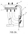
- Figure 2brepresents a front, schematic, sectional view of the detail of the hood according to a different embodiment
- Figure 3represents a perspective view of an apparatus according to the invention
- Figure 4represents a perspective view of a variation of the apparatus in Figure 3 ;
- Figure 5represents a side view of a further embodiment of the apparatus according to the invention.
- an apparatus according to the inventionis generally indicated with the reference numeral 1.
- the apparatus according to the inventioncomprises a blowing hood 2a, a suctioning hood 2b, and means 3 to support the hoods 2a, 2b.
- the blowing hood 2ais adapted to generate a laminar flow of sterile air.
- the blowing hood 2acomprises a microfilter 21, for example, of the HEPA type.
- the microfilterhas an efficiency above 99.99% on particles having a diameter up to 0.3 ⁇ m.
- the microfilterhas an efficiency above 99.997%, so as to essentially eliminate all the contaminating agents from the air flow.
- the blowing hood 2afurther comprises a prefilter upstream the HEPA microfilter.
- a prefilterupstream the HEPA microfilter.
- the prefilterhas an efficiency of about 75%.
- the blowing hood 2acomprises a fan motor 22, preferably causing low noise.
- the blowing hood 2acomprises a lighting lamp (not shown), for example, an incandescent or fluorescent lamp.
- the lighting lampis adapted to illuminate the operative area hit by the laminar flow.
- the lighting lampis adapted to provide a sufficient luminosity to allow safely operating.
- the blowing hood 2afurther comprises a germicidal lamp (not shown), for example, a UV germicidal lamp.
- the blowing hood 2ais capable of ensuring a high degree of sterility to the operative area directly hit by the laminar flow.
- the suctioning hood 2balso per se known, is connected to the blowing hood 2a by flexible jointing means 23, such as a connecting member with coaxial rings o a swing joint connector.
- the suctioning hood 2bwill be generally arranged in an essentially perpendicular position relative to the blowing hood 2a, but it will be able to be oriented as desired by the user by means of the flexible jointing means 23.
- the connecting means between blowing hood 2a and suctioning hood 2bare fixed, and consist in an L-shaped member that keeps the suctioning hood 2b in a perpendicular position relative to the blowing hood 2a.
- the suctioning hood 2bcomprises a filter 24, which can be a HEPA microfilter as the one described above, or a HEPA prefilter-microfilter system as described above.
- the suctioning hood 2bcomprises suction means, such as a fan motor 25, which are adapted to suck air from the intervention zone and eject it to the exterior via a suitable grid which is arranged, for example, on the suctioning hood 2b rear part.
- suction meanssuch as a fan motor 25, which are adapted to suck air from the intervention zone and eject it to the exterior via a suitable grid which is arranged, for example, on the suctioning hood 2b rear part.
- the suctioning hood 2bis connected to the blowing hood 2a through flexible o rigid connecting means 26 which put the suctioning hood 2b, downstream the filter 24, into flow communication with the blowing hood 2a, upstream the fan motor 22.
- the blowing hood 2a fan motor 22also acts as a suction means for the suctioning hood 2b, which thereby does not need suction means of its own.
- the external air passage way grids in the blowing hood 2awill have to be suitably sized in order to properly balance the air flows.
- the connecting means 26typically consist in a rigid or flexible tube, which is adapted to maintain the suctioning hood 2b orientation preset by the operator.
- blowing hood 2a and suctioning hood 2bform a system for the generation and treatment of a laminar air flow in the intervention zone.
- the support means 3 shown in the Figuresare directly connected to the blowing hood 2a, but nothing prevents their connection to the suctioning hood 2b as an alternative, according to the apparatus constructive needs.
- the support means 3are adapted to allow the adjustment of the same blowing hood 2a positioning and the adjustment of said laminar flow orientation.
- the support means 3are adapted to ensure the stability of the blowing hood 2a positioning and the laminar flow orientation.
- hood positioning and the flow orientationdo not accidentally vary under the action of the typical loads acting on a hood during the use thereof.
- the support means 3are adapted so that the hood positioning and orientation do not vary under the action of the intrinsic weight of the hood, under the action of the reaction force created by the air flow ejection, under the action of the force that the operator has to apply in order to actuate the optional controls arranged on the same hood, etc.
- the support means 3allow the user positioning the blowing hood 2a within the medical centre, office, or laboratory at will.
- the support means 3further allow arranging the blowing hood 2a in such a manner as to orientate the laminar flow produced by it in the direction desired by the operator.
- the support means 3allow stably keeping the blowing hood 2a, and, as a consequence, the suctioning hood 2b, in the desired position, and stably keeping the laminar flow in the desired direction.
- the apparatus 1 according to the inventionis particularly adapted for use in medical centres, offices, or laboratories in which a high degree of sterility is required in a limited operative area, but which cannot be decided in advance, and which can be variously located.
- the preferred use of the apparatus 1 according to the inventionis the use in offices or medical centres where small interventions are performed on patients, requiring a high degree of local sterility.
- the apparatus 1has been devised for podiatric interventions.
- the support means 3comprise a base 30 and a series of shafts 31 connected by joints 32.
- the base 30is so manufactured as to ensure a high stability of the apparatus, for example, by comprising a large rest surface (see Figures 3 and 4 ), or by comprising a ballast, or anchoring means, or the like.
- the base 30comprises mobility means 301 adapted to provide a high ease to the base 30 movement during the apparatus 1 handling step.
- mobility means 301can comprise wheels, rolls, spheres, or the like.
- the base 30comprises detent means 302 which are adapted to increment the stability and to limit the mobility of the base 30 once the apparatus 1 handling step has been completed.
- the detent means 302can, for example, comprise retainers adapted to act on the surface on which the base 30 is mobile, or brackets adapted to act on the mobility means 301, where present.
- Shafts 31 and joints 32are so implemented as to confer the blowing hood 2a all degrees of freedom which are deemed to be necessary in the specific case.
- a fixed length shaft 311, and a telescopic shaft 312are employed. Such solution allows, once the apparatus 1 base 30 has been secured, achieving a blowing hood 2 translation along the telescopic shaft 312 direction.
- a planar hinge joint 321, and a ball and socket hinge joint 322are employed.
- the planar hinge joint 321allows the two arms connected thereto a relative rotation around a hinge axis. In other words, the planar hinge joint 321 allows obtaining a hood 2a rotation around the hinge axis, which is perpendicular to the directions of the two shafts connected to the hinge 321.
- the ball and socket hinge joint 322allows the two arms connected thereto any relative rotations in the space, around a hinge centre.
- the ball and socket hinge joint 322allows obtaining a hood 2a rotation around the hinge centre.
- a box couplingcan be employed.
- the box couplingallows a rotation around the shaft 31 axis to which it is connected.
- the box couplingallows obtaining a hood 2a rotation around the shaft axis connected to the joint.
- blowing hood 2awhich is arranged at the end of one shafts 31 and joints 32 chain enjoys the sum of all the degrees of freedom given by each shaft 31 and each joint 32.
- the telescopic shafts and the jointscomprise means to continuously putting up a predetermined resistance to the movement, so as to prevent undesired movements under the action of the typical loads acting on the blowing hood 2a during the use thereof.
- Such meanscan, for example, comprise systems to obtain a discrete step movement, for example, snap systems defining predefined successive stabile balance positions.
- the telescopic shafts 312 and the hinge joints 32comprise means to increment and/or decrease the resistance they oppose to the movement.
- Such meanscan, for example, comprise screw tightening ring nuts.
- the apparatus 1further comprises a furnishing item adapted for use in the medical centre, office, or laboratory.
- such furnishing itemis an armchair or bed 4 adapted to receive a patient.
- the armchair 4 and the blowing hood 2ashare the base 30.
- support means 3 and armchair 4share the structure 34 which from the base 30 extends to the level of an arm rest 40.
- the support means 3extend from the base 30 independently from the armchair 4.
- the positioning stability of the blowing hood 2takes advantage from the base 30 width, and from the overall mass weighting down on it, thus making it particularly firm.
- such masscomprises the armchair mass and, when the apparatus 1 is in use, the patient mass.
- the armchair 4is of the type conventionally used in the podiatric medical centres.
- Such armchairgenerally comprises means for patient handling.
- the patient handling meanscan comprise, for example, a reclinable backrest 41, a rocking seat 42, a mechanism 43 adapted to lift the whole armchair 4.
- the armchair represented in the Figures 3 and 4further comprises two legrests 44 adapted to raise and lower the patient's legs, one independently to the other.
- the arm rest 40' from which the support means 3 extendis fixed relative to the armchair 4.
- the patientis unable to access and leave the armchair 4 from the side carrying the support means 3.
- the opposite arm rest 40"is mobile, in order to aid access to and rising from the armchair.
- the armchair or bedcan be of a different type, for example, of the type used in the medical centres of dentistry, otorhinolaryngology, gynaecology, general surgery, veterinary, etc.
- the armchair or bedcan still be of a different type, for example, of the type used in the offices where aesthetical treatments, tattoos, etc., are carried out.
- the furnishing item included in the apparatus 1 according to the inventionis a closet 5, for example, provided with drawers and shelves in order to put the instruments in use in the medical centre, office, or laboratory back.
- Such embodimentallows, similarly to those in Figures 3 and 4 , taking advantage of the mass of the furnishing item and the instruments contained therein, in order to confer stability to the support means 3. Furthermore, when the blowing hood is not in use, the apparatus 1 can take a retracted configuration, which requires slightly more room compared to the room needed by a standard closet to shelve instruments.
- the apparatus 1allows locally obtaining a high level of sterility, so as to be able to operate on patients with the proper safety. Thanks to the provision of the suctioning hood 2b, there is no dispersion into the environment of the organic residues optionally originating during the intervention (epidermis flakes or fragments and callous tissue, nails, etc.), which allows confining the intervention zone to the protection of both the environment and the operator.
- the apparatus 1provides a system for the generation and treatment of air, composed of the blowing hood 2a - suctioning hood 2b unit, which can be easily arranged in the most suitable position from time to time for the specific need, and the laminar flow of which can be easily arranged from time to time in the most suitable orientation for the specific need.
- the operatorhas to identify the area of the patient's body on which it is necessary to operate.
- the operatorgenerates the sterile air laminar flow by means of the blowing hood 2a.
- the operatorselects a blowing hood 2a positioning and, optionally, of the suctioning hood 2b positioning, and adjusts the laminar flow orientation so that the same laminar flow hits the area of the patient's body identified before.
Landscapes
- Health & Medical Sciences (AREA)
- Surgery (AREA)
- Engineering & Computer Science (AREA)
- Biomedical Technology (AREA)
- Life Sciences & Earth Sciences (AREA)
- Animal Behavior & Ethology (AREA)
- General Health & Medical Sciences (AREA)
- Public Health (AREA)
- Veterinary Medicine (AREA)
- Accommodation For Nursing Or Treatment Tables (AREA)
Description
- The present invention relates to a mobile laminar flow hood specifically devised for use in podiatry, and to a podiatric apparatus to which such hood is associated. In particular, the hood of the invention is a hood adapted to generate a laminar flow of sterile air.
- In the field of small interventions in patients which are performed in offices o medical centres, the problem of operating with a high degree of local sterility, in order to ensure health and safety for the patient is known.
- Differently from the hospital operating rooms, in which a high overall degree of sterility is necessary and ensured, in the medical centres of podiatry, dentistry, otorhinolaryngology, gynaecology, general surgery, veterinary, etc., and in those offices in which esthetical treatments, tattoos, etc., are performed, a high degree of sterility can be necessary in an extremely reduced operative area. Such need does not justify the extremely burdensome use of the methods and apparatuses typically employed in the hospital operating rooms.
- In the field of the laboratory apparatuses, blowing hoods are known which are adapted to achieve a high degree of sterility in an operative area of a reduced extension.
- Such known hoods suck air from the environment, microfiltrate the same, and blow it in the form of a laminar flow onto the operative area. Such an hood is known from
WO 00/04976 - The air microfiltration occurs by means of HEPA-type filters (High Efficiency Particulate Air), the efficiency of which complies with the EN 1822 standards. A typically required efficiency for these filters is above 99.99% for particles having a diameter up to 0.3 µm. This high filtering power essentially eliminates all the contaminating agents from the air flow.
- The laminar flow generated by the blowing hood consists in a series of mutually parallel fluid layers, all of which have the same speed. The typical speeds of such flows are approximately in the range of 0.5 m/s. The laminar flow, due to the absence of vortexes, keeps a high separation between what is immersed in the flow and what is outside it.
- Thanks to the microfiltration of air and the flow laminarity, such hoods allow a high protection both of the operative area directly hit by the flow, and also of the operator standing outside it. In fact, cross-contaminations and environmental contaminations are avoided by such hoods.
- However, such hoods are not adapted for use in small interventions on patients at the doctor's offices and medical centres cited above.
- In fact, they are mounted on fixed structures, being generally accessible only from a side, and closed at the other three sides, so as to create very sterile cabinets. The sterile cabinets are intended to be fixedly positioned inside the laboratory. They cannot be easily transported, and allow operating only on samples having predefined dimensions, in particular on samples which can be entirely introduced into the same cabinet.
- Furthermore, in some applications, such as, in particular, podiatry, small organic residues in the form of powders are generated during operation, which are then dispersed into the environment, together with the relative bacterial charge. A laminar flow hood as those described above tends to promote the dispersion thereof, since the air flow removes the powders from the operative zone.
- This can lead to the diffusion of bacterial infections or allergies. In fact, it is known that the podiatric operators often develop an antibody response which is higher than that of average people, which is probably due to the exposure to allergenic factors such as the above-mentioned powders.
- Therefore, object of the present invention is to provide an apparatus having such characteristics as to meet the needs set forth above, and which have not been met by the prior art.
- A task of the present invention is to provide an apparatus which allows operating on patients with a high sterility degree, therefore with the proper safety, while not dispersing organic residues into the surrounding environment.
- Another task of the present invention is to provide an apparatus capable of creating a sterile operative area which can be readily prearranged from time to time in the more suitable position for that specific need.
- Such object and such tasks are achieved by an apparatus in accordance with the annexed claims, the definitions of which are an integral part of the present description.
- In order to better understand the invention, and appreciate the advantages thereof, some exemplary, nonlimiting embodiments thereof are described herein below, with reference to the annexed drawings, in which:
Figure 1 represents a side top view of an embodiment of the apparatus according to the invention;Figure 2a represents a front, schematic, sectional view of the detail of the hood according to the invention;Figure 2b represents a front, schematic, sectional view of the detail of the hood according to a different embodiment;Figure 3 represents a perspective view of an apparatus according to the invention;Figure 4 represents a perspective view of a variation of the apparatus inFigure 3 ;Figure 5 represents a side view of a further embodiment of the apparatus according to the invention.- With reference to the annexed Figures, an apparatus according to the invention is generally indicated with the
reference numeral 1. The apparatus according to the invention comprises a blowinghood 2a, a suctioninghood 2b, and means 3 to support thehoods - The blowing
hood 2a, the functioning principle of which isper se known, is adapted to generate a laminar flow of sterile air. - In accordance with an embodiment, the blowing
hood 2a comprises amicrofilter 21, for example, of the HEPA type. In accordance with an embodiment, the microfilter has an efficiency above 99.99% on particles having a diameter up to 0.3 µm. Preferably, the microfilter has an efficiency above 99.997%, so as to essentially eliminate all the contaminating agents from the air flow. - In accordance with an embodiment, the blowing
hood 2a further comprises a prefilter upstream the HEPA microfilter. Such prefilter allows an easy removal and a quick replacement, and allows extending the service life of the microfilter. In accordance with an embodiment, the prefilter has an efficiency of about 75%. - In accordance with an embodiment, the blowing
hood 2a comprises afan motor 22, preferably causing low noise. - In accordance with an embodiment, the blowing
hood 2a comprises a lighting lamp (not shown), for example, an incandescent or fluorescent lamp. The lighting lamp is adapted to illuminate the operative area hit by the laminar flow. Preferably, the lighting lamp is adapted to provide a sufficient luminosity to allow safely operating. - In accordance with an embodiment, the blowing
hood 2a further comprises a germicidal lamp (not shown), for example, a UV germicidal lamp. - Therefore, the blowing
hood 2a is capable of ensuring a high degree of sterility to the operative area directly hit by the laminar flow. - The suctioning
hood 2b, alsoper se known, is connected to the blowinghood 2a by flexible jointing means 23, such as a connecting member with coaxial rings o a swing joint connector. The suctioninghood 2b will be generally arranged in an essentially perpendicular position relative to the blowinghood 2a, but it will be able to be oriented as desired by the user by means of the flexible jointing means 23. - In a simplified form, the connecting means between blowing
hood 2a and suctioninghood 2b are fixed, and consist in an L-shaped member that keeps the suctioninghood 2b in a perpendicular position relative to the blowinghood 2a. - The
suctioning hood 2b comprises afilter 24, which can be a HEPA microfilter as the one described above, or a HEPA prefilter-microfilter system as described above. - In an embodiment (
Figure 2a ), thesuctioning hood 2b comprises suction means, such as afan motor 25, which are adapted to suck air from the intervention zone and eject it to the exterior via a suitable grid which is arranged, for example, on the suctioninghood 2b rear part. - In a different embodiment (
Figure 2b ), thesuctioning hood 2b is connected to the blowinghood 2a through flexible origid connecting means 26 which put thesuctioning hood 2b, downstream thefilter 24, into flow communication with the blowinghood 2a, upstream thefan motor 22. In this manner, the blowinghood 2afan motor 22 also acts as a suction means for the suctioninghood 2b, which thereby does not need suction means of its own. In such a case, the external air passage way grids in the blowinghood 2a will have to be suitably sized in order to properly balance the air flows. - The
connecting means 26 typically consist in a rigid or flexible tube, which is adapted to maintain thesuctioning hood 2b orientation preset by the operator. - In general, blowing
hood 2a and suctioninghood 2b form a system for the generation and treatment of a laminar air flow in the intervention zone. - The support means 3 shown in the Figures are directly connected to the blowing
hood 2a, but nothing prevents their connection to the suctioninghood 2b as an alternative, according to the apparatus constructive needs. The support means 3 are adapted to allow the adjustment of the same blowinghood 2a positioning and the adjustment of said laminar flow orientation. At the same time, the support means 3 are adapted to ensure the stability of the blowinghood 2a positioning and the laminar flow orientation. - By the term 'stability' is meant, herein and below, that the hood positioning and the flow orientation do not accidentally vary under the action of the typical loads acting on a hood during the use thereof.
- In particular, the support means 3 are adapted so that the hood positioning and orientation do not vary under the action of the intrinsic weight of the hood, under the action of the reaction force created by the air flow ejection, under the action of the force that the operator has to apply in order to actuate the optional controls arranged on the same hood, etc.
- The support means 3 allow the user positioning the
blowing hood 2a within the medical centre, office, or laboratory at will. The support means 3 further allow arranging the blowinghood 2a in such a manner as to orientate the laminar flow produced by it in the direction desired by the operator. Finally, the support means 3 allow stably keeping the blowinghood 2a, and, as a consequence, thesuctioning hood 2b, in the desired position, and stably keeping the laminar flow in the desired direction. - As it can be appreciated in view of the description heretofore reported, the
apparatus 1 according to the invention is particularly adapted for use in medical centres, offices, or laboratories in which a high degree of sterility is required in a limited operative area, but which cannot be decided in advance, and which can be variously located. - The preferred use of the
apparatus 1 according to the invention is the use in offices or medical centres where small interventions are performed on patients, requiring a high degree of local sterility. In particular, theapparatus 1 has been devised for podiatric interventions. - Other possible uses of the
apparatus 1 according to the invention are those in those laboratories where samples are being treated, having such dimensions as to not be capable of being introduced into a sterile laminar flow cabinet of a conventional type. - In accordance with an embodiment, the support means 3 comprise a
base 30 and a series ofshafts 31 connected byjoints 32. - The
base 30 is so manufactured as to ensure a high stability of the apparatus, for example, by comprising a large rest surface (seeFigures 3 and4 ), or by comprising a ballast, or anchoring means, or the like. - In accordance with an embodiment, the
base 30 comprises mobility means 301 adapted to provide a high ease to the base 30 movement during theapparatus 1 handling step. Such means 301 can comprise wheels, rolls, spheres, or the like. - In accordance with an embodiment, the
base 30 comprises detent means 302 which are adapted to increment the stability and to limit the mobility of the base 30 once theapparatus 1 handling step has been completed. The detent means 302 can, for example, comprise retainers adapted to act on the surface on which thebase 30 is mobile, or brackets adapted to act on the mobility means 301, where present. Shafts 31 andjoints 32 are so implemented as to confer theblowing hood 2a all degrees of freedom which are deemed to be necessary in the specific case.- With reference, for example, to
Figure 1 , a fixedlength shaft 311, and atelescopic shaft 312 are employed. Such solution allows, once theapparatus 1base 30 has been secured, achieving a blowing hood 2 translation along thetelescopic shaft 312 direction. - With reference, for example, to
Figure 4 , a planar hinge joint 321, and a ball and socket hinge joint 322 are employed. - The planar hinge joint 321 allows the two arms connected thereto a relative rotation around a hinge axis. In other words, the planar hinge joint 321 allows obtaining a
hood 2a rotation around the hinge axis, which is perpendicular to the directions of the two shafts connected to thehinge 321. - Instead, the ball and socket hinge joint 322 allows the two arms connected thereto any relative rotations in the space, around a hinge centre. In other words, the ball and socket hinge joint 322 allows obtaining a
hood 2a rotation around the hinge centre. - In another embodiment, a box coupling can be employed. The box coupling allows a rotation around the
shaft 31 axis to which it is connected. In other words, the box coupling allows obtaining ahood 2a rotation around the shaft axis connected to the joint. - As one skilled in the art will easily understand, the blowing
hood 2a which is arranged at the end of oneshafts 31 andjoints 32 chain enjoys the sum of all the degrees of freedom given by eachshaft 31 and each joint 32. - In accordance with an embodiment, the telescopic shafts and the joints comprise means to continuously putting up a predetermined resistance to the movement, so as to prevent undesired movements under the action of the typical loads acting on the blowing
hood 2a during the use thereof. - Such means can, for example, comprise systems to obtain a discrete step movement, for example, snap systems defining predefined successive stabile balance positions.
- In accordance with another embodiment, the
telescopic shafts 312 and the hinge joints 32 comprise means to increment and/or decrease the resistance they oppose to the movement. - Such means can, for example, comprise screw tightening ring nuts.
- In accordance with an embodiment, the
apparatus 1 according to the invention further comprises a furnishing item adapted for use in the medical centre, office, or laboratory. - In accordance with a preferred embodiment, such furnishing item is an armchair or
bed 4 adapted to receive a patient. In the specific embodiments represented inFigures 3 and4 , thearmchair 4 and the blowinghood 2a (to which thesuctioning hood 2b is connected) share thebase 30. - In particular, in the embodiment of
Figure 3 , support means 3 andarmchair 4 share thestructure 34 which from thebase 30 extends to the level of anarm rest 40. - Instead, in the embodiment of
Figure 4 , the support means 3 extend from the base 30 independently from thearmchair 4. - In these embodiments, the positioning stability of the blowing hood 2 takes advantage from the base 30 width, and from the overall mass weighting down on it, thus making it particularly firm. In fact, such mass comprises the armchair mass and, when the
apparatus 1 is in use, the patient mass. - In the embodiments of the
apparatus 1 represented in theFigures 3 and4 , thearmchair 4 is of the type conventionally used in the podiatric medical centres. Such armchair generally comprises means for patient handling. The patient handling means can comprise, for example, areclinable backrest 41, a rockingseat 42, amechanism 43 adapted to lift thewhole armchair 4. The armchair represented in theFigures 3 and4 further comprises twolegrests 44 adapted to raise and lower the patient's legs, one independently to the other. - In the embodiment of
Figure 3 , in which support means 3 andarmchair 4 share part of the structure, the arm rest 40' from which the support means 3 extend is fixed relative to thearmchair 4. In fact, the patient is unable to access and leave thearmchair 4 from the side carrying the support means 3. Instead, theopposite arm rest 40" is mobile, in order to aid access to and rising from the armchair. - In accordance with other possible embodiments of the
apparatus 1 according to the invention, the armchair or bed can be of a different type, for example, of the type used in the medical centres of dentistry, otorhinolaryngology, gynaecology, general surgery, veterinary, etc. - In accordance with further possible embodiments of the
apparatus 1 according to the invention, the armchair or bed can still be of a different type, for example, of the type used in the offices where aesthetical treatments, tattoos, etc., are carried out. - In accordance with the embodiment represented in
Figure 5 , the furnishing item included in theapparatus 1 according to the invention is a closet 5, for example, provided with drawers and shelves in order to put the instruments in use in the medical centre, office, or laboratory back. - Such embodiment allows, similarly to those in
Figures 3 and4 , taking advantage of the mass of the furnishing item and the instruments contained therein, in order to confer stability to the support means 3.
Furthermore, when the blowing hood is not in use, theapparatus 1 can take a retracted configuration, which requires slightly more room compared to the room needed by a standard closet to shelve instruments. - As those skilled in the art will be certainly able to appreciate from the description reported above, the
apparatus 1 according to the invention allows locally obtaining a high level of sterility, so as to be able to operate on patients with the proper safety. Thanks to the provision of thesuctioning hood 2b, there is no dispersion into the environment of the organic residues optionally originating during the intervention (epidermis flakes or fragments and callous tissue, nails, etc.), which allows confining the intervention zone to the protection of both the environment and the operator. - Furthermore, the
apparatus 1 according to the invention provides a system for the generation and treatment of air, composed of the blowinghood 2a - suctioninghood 2b unit, which can be easily arranged in the most suitable position from time to time for the specific need, and the laminar flow of which can be easily arranged from time to time in the most suitable orientation for the specific need. - In the following, a method of use of the
apparatus 1 is described below, in accordance with a further aspect of the invention. - First, the operator has to identify the area of the patient's body on which it is necessary to operate.
- Then, the operator generates the sterile air laminar flow by means of the blowing
hood 2a. - Then, the operator selects a blowing
hood 2a positioning and, optionally, of thesuctioning hood 2b positioning, and adjusts the laminar flow orientation so that the same laminar flow hits the area of the patient's body identified before. - Then, the operator makes the blowing
hood 2a and thesuctioning hood 2b positioning, and the laminar flow orientation, stable through said support means 3. - Finally, the operator can safely operate on the area of the patient's body identified before.
- It shall be apparent that to the
apparatus 1 according to the present invention, one of ordinary skill in the art, with the aim of meeting contingent, specific needs will be able to make further modifications and variations, all anyhow falling within in the protection scope of the following claims.
Claims (15)
- An apparatus (1) comprising a system for the generation and treatment of a laminar air flow in an intervention zone, and means (3) to support said system for the generation and treatment of a laminar air flow, wherein said system for the generation and treatment of a laminar air flow comprises a blowing hood (2a) which is adapted to generate a laminar flow of sterile air towards said intervention zone, and a suctioning hood (2b) which is adapted to suck from said intervention zone said laminar flow of sterile air,characterized in that said support means (3) comprise a base (30) and a pluralité of shafts (31) connected through joints (32), and in which said base (30) comprises mobility means (301) adapted to aid the base (30) movement during a handling step of said apparatus (1), wherein the suctioning hood (2b) is connected to the blowing hood (2a) and wherein the said support means (3) are directly connected to the blowing hood (2a) or alternatively to the suctioning hood (2b).
- The apparatus (1) according to claim 1, wherein said support means (3) are adapted to allow the adjustment of said blowing hood (2a) positioning and the adjustment of said laminar flow orientation, and are further adapted to ensure said positioning and said orientation stability.
- The apparatus (1) according to claim 1 or 2, wherein said blowing hood (2a) and/or said suctioning hood (2b) comprise a microfilter (21, 24) of the HEPA type.
- The apparatus (1) according to claim 3, wherein said microfilter (21, 24) has an efficiency above 99.99% on particles having a diameter up to 0.3 µm.
- The apparatus (1) according to claim 3 or 4, wherein said blowing hood (2a) and/or said suctioning hood (2b) comprise a prefilter arranged upstream said HEPA microfilter (21, 24), and having a efficiency of about 75%.
- The apparatus (1) according to any claim 1 to 5, wherein said blowing hood (2a) comprises a low noise fan motor (22).
- The apparatus (1) according to any claim 1 to 6, wherein said blowing hood (2a) comprises a lightning lamp.
- The apparatus (1) according to any claim 1 to 7, wherein said blowing hood (2a) comprises a UV germicidal lamp.
- The apparatus (1) according to any claim 1 to 8, wherein said suctioning hood (2b) is connected to said blowing hood (2a) through flexible or rigid connecting means (23), and comprises suction means (25) and an opening for the exit of air which has been sucked and filtered to the environment.
- The apparatus (1) according to any claim 1 to 8, wherein said suctioning hood (2b) is connected to said blowing hood (2a) via flexible or rigid connecting means (26), which put the suctioning hood (2b), downstream the filter (24), into flow communication with the blowing hood (2a), upstream the fan motor (22), so that said blowing hood (2a) fan motor (22) also acts as a suction means (25) for the suctioning hood (2b).
- The apparatus (1) according to claim 10, wherein said connecting means (26) are a flexible or rigid tube.
- The apparatus according to any claim 9 to 11, wherein said connecting means (23) or said connecting means (26) are so configured as to arrange said suctioning hood (2b) in an essentially perpendicular position relative to said blowing hood (2a), said system for the generation and treatment of the laminar air flow taking an essentially L-shaped configuration.
- The apparatus (1) according to any claim 1 to 12, comprising detent means (302) adapted to limit the base (30) mobility once a handling step of said apparatus (1) has been completed.
- The apparatus (1) according to any claim 1 to 13, wherein said plurality of shafts (31) comprises at least one telescopic shaft (312) and in which said plurality of joints (32) comprises at least one planar hinge joint (321), and at least one ball and socket hinge joint (322), and/or at least one box coupling (323), and in which said telescopic shafts (312) and said joints (32) comprise means to constantly oppose a predetermined resistance to the movement.
- The apparatus (1) according to any claim 1 to 14, comprising a podiatric armchair (4) and in which said support means (3) are directly connected to said podiatric armchair (4).
Priority Applications (3)
| Application Number | Priority Date | Filing Date | Title |
|---|---|---|---|
| ES08425636TES2427125T3 (en) | 2008-09-29 | 2008-09-29 | Mobile laminar flow hood for use in podiatry |
| EP08425636.1AEP2168546B1 (en) | 2008-09-29 | 2008-09-29 | Mobile laminar flow hood for use in podiatry |
| US12/565,656US8465576B2 (en) | 2008-09-29 | 2009-09-23 | Mobile laminar flow hood for use in podiatry |
Applications Claiming Priority (1)
| Application Number | Priority Date | Filing Date | Title |
|---|---|---|---|
| EP08425636.1AEP2168546B1 (en) | 2008-09-29 | 2008-09-29 | Mobile laminar flow hood for use in podiatry |
Publications (2)
| Publication Number | Publication Date |
|---|---|
| EP2168546A1 EP2168546A1 (en) | 2010-03-31 |
| EP2168546B1true EP2168546B1 (en) | 2013-06-05 |
Family
ID=40344960
Family Applications (1)
| Application Number | Title | Priority Date | Filing Date |
|---|---|---|---|
| EP08425636.1AActiveEP2168546B1 (en) | 2008-09-29 | 2008-09-29 | Mobile laminar flow hood for use in podiatry |
Country Status (3)
| Country | Link |
|---|---|
| US (1) | US8465576B2 (en) |
| EP (1) | EP2168546B1 (en) |
| ES (1) | ES2427125T3 (en) |
Families Citing this family (17)
| Publication number | Priority date | Publication date | Assignee | Title |
|---|---|---|---|---|
| JP5859960B2 (en)* | 2009-07-17 | 2016-02-16 | テクニカル ユニバーシティ オブ デンマークTechnical University Of Denmark | Devices and methods for reducing the spread of microorganisms and health hazards in the air and / or for protecting against microorganisms and health hazards in the air |
| AU2012238632B2 (en)* | 2011-04-06 | 2013-11-28 | Airsonett Ab | Temperature controlled laminair air flow device |
| DE102011108076A1 (en)* | 2011-07-21 | 2013-01-24 | Ladwig Feinwerktechnik Gmbh | suction |
| US9351896B2 (en)* | 2012-11-05 | 2016-05-31 | Joseph John Urban | Portable aseptic unit and process for the aseptic preparation and aseptic delivery of drugs, devices and cosmetics to humans or animals in an aseptic environment |
| WO2014162603A1 (en)* | 2013-04-05 | 2014-10-09 | 日科ミクロン株式会社 | Local cleaned air supply device |
| US10702435B2 (en)* | 2016-11-16 | 2020-07-07 | Thunderhill Investments, LLC | Medical air treatment device |
| US12016802B2 (en)* | 2019-10-22 | 2024-06-25 | Aerobiotix. Llc | Air treatment system for operating or patient rooms |
| US11357590B1 (en)* | 2020-03-20 | 2022-06-14 | David J. Ahearn | Safely scavenge screen assembly |
| US11317986B1 (en)* | 2020-03-20 | 2022-05-03 | David J. Ahearn | Safely scavenge screen assembly |
| US11859864B1 (en)* | 2020-05-18 | 2024-01-02 | Wunderlich-Malec Engineering, Inc. | Particulate and virus barrier |
| USD942017S1 (en) | 2020-06-11 | 2022-01-25 | David J. Ahearn | Protective vacuum shield for personal service providers |
| USD930841S1 (en) | 2020-06-11 | 2021-09-14 | David J. Ahearn | Protective vacuum shield for personal service providers |
| WO2022039590A1 (en)* | 2020-08-19 | 2022-02-24 | University Of Malaya | Containment barrier assembly for use in aerosolized generating procedure |
| WO2022063948A1 (en)* | 2020-09-25 | 2022-03-31 | Ethera | Air purification system |
| CN112515786A (en)* | 2020-12-09 | 2021-03-19 | 南昌大学 | Blow-suction type exhaust device for dental chair |
| DE102021100415A1 (en) | 2021-01-12 | 2022-07-14 | SLT Schanze Lufttechnik GmbH & Co. KG | Furniture system with a facility for treating room air |
| WO2022216636A1 (en)* | 2021-04-05 | 2022-10-13 | Claerosol Llc | Systems and methods for producing a controlled operating environment |
Family Cites Families (18)
| Publication number | Priority date | Publication date | Assignee | Title |
|---|---|---|---|---|
| US3537447A (en)* | 1967-06-26 | 1970-11-03 | Champion Spark Plug Co | Medical shielding structure |
| US3820536A (en)* | 1972-01-10 | 1974-06-28 | W Anspach | Apparatus for providing clean air at a surgical area |
| US4023472A (en)* | 1974-06-04 | 1977-05-17 | Ciba-Geigy Corporation | Apparatus for producing a laminar flow |
| US4092136A (en)* | 1976-09-14 | 1978-05-30 | William D. Farnham | Air filtering system |
| DE3612362A1 (en)* | 1986-04-12 | 1987-10-15 | Hoelter Heinz | Air-purifying device for hospital beds |
| US5160517A (en)* | 1990-11-21 | 1992-11-03 | Hicks Richard E | System for purifying air in a room |
| US5129928A (en)* | 1991-06-26 | 1992-07-14 | Air Innovative Systems, Inc. | Environment treatment |
| US5858041A (en)* | 1997-08-22 | 1999-01-12 | David Luetkemeyer | Clean air system |
| US6099607A (en)* | 1998-07-22 | 2000-08-08 | Haslebacher; William J. | Rollably positioned, adjustably directable clean air delivery supply assembly, for use in weather protected environments to provide localized clean air, where activities require clean air quality per strict specifications |
| US6626971B1 (en)* | 1998-09-15 | 2003-09-30 | Siemens Axiva Gmbh & Co. Kg | Method and device for protecting persons and/or products from air-borne particles |
| US6444002B1 (en)* | 1999-09-14 | 2002-09-03 | Billy Mai | Nail salon air purification system |
| SE516775C2 (en)* | 2000-06-05 | 2002-02-26 | Jan Kristensson | Method and apparatus for providing clean air in a room |
| US6471754B2 (en)* | 2000-09-28 | 2002-10-29 | Tahsin Ammouri | Purification system for tobacco-generated secondhand smoke |
| SE521052C3 (en)* | 2001-03-20 | 2003-10-22 | Toul Meditech Ab | Air purification device intended for purification of air in sensitive environments, method for arranging air purification in sensitive environments and use of said air purification device |
| US6916238B2 (en)* | 2001-07-10 | 2005-07-12 | David J. Korman | Canopy air delivery system |
| US20040192186A1 (en)* | 2003-03-24 | 2004-09-30 | Precision Air Products Co. | Portable air filtration apparatus |
| US6869458B2 (en)* | 2003-05-05 | 2005-03-22 | Sanki Engineering Co., Ltd. | Bioclean room unit |
| SE532219C2 (en)* | 2006-02-28 | 2009-11-17 | Airsonett Ab | Method and apparatus for providing a clean air zone at an operating area in the medical field and use of said device |
- 2008
- 2008-09-29EPEP08425636.1Apatent/EP2168546B1/enactiveActive
- 2008-09-29ESES08425636Tpatent/ES2427125T3/enactiveActive
- 2009
- 2009-09-23USUS12/565,656patent/US8465576B2/enactiveActive
Also Published As
| Publication number | Publication date |
|---|---|
| US8465576B2 (en) | 2013-06-18 |
| EP2168546A1 (en) | 2010-03-31 |
| ES2427125T3 (en) | 2013-10-28 |
| US20100081368A1 (en) | 2010-04-01 |
Similar Documents
| Publication | Publication Date | Title |
|---|---|---|
| EP2168546B1 (en) | Mobile laminar flow hood for use in podiatry | |
| US20210393359A1 (en) | Sterile surgical drape for ophthalmic surgery | |
| US20190234645A1 (en) | Sterile airflow delivery system | |
| US11555604B2 (en) | Airflow-channeling surgical light system and method | |
| US10537655B2 (en) | Device for providing a volume of sterile air | |
| US11219500B2 (en) | Aerosol reduction systems and methods | |
| CN116056744B (en) | Airborne pathogen extraction system | |
| US20100003912A1 (en) | Medical mini-environment device | |
| JP2011031019A (en) | Infection prevention device and infection prevention system | |
| US20080188170A1 (en) | Mobile laminar flow hood | |
| US20070042702A1 (en) | Medical mini-environment device | |
| EP1462076B1 (en) | Operation unit | |
| EP3888611A1 (en) | Air purifying apparatus for purifying air in an isolation space | |
| EP1803431A1 (en) | Mobile laminar flow hood | |
| JP5372647B2 (en) | Infection prevention device and infection prevention system | |
| WO2008004925A1 (en) | Air filter for clean rooms including inclined filter elements | |
| JP2001238923A (en) | Treating table for medical use | |
| JP2006150327A (en) | Self-supporting local clean air supply device | |
| CN211835204U (en) | Clinical adjunctie therapy device of backbone surgery | |
| CN210772563U (en) | Laminar bed | |
| CN211986419U (en) | Sterilizing device for operating room nursing | |
| Howorth | Prevention of Airborne Transmission of Infection Past, Present and Future | |
| ITMC20070033U1 (en) | INTEGRATED WORK STATION, PREFERABLY FOR MEDICAL AND PARAMEDIC PERFORMANCES. | |
| WO2005002488A1 (en) | Movable workstation |
Legal Events
| Date | Code | Title | Description |
|---|---|---|---|
| PUAI | Public reference made under article 153(3) epc to a published international application that has entered the european phase | Free format text:ORIGINAL CODE: 0009012 | |
| AK | Designated contracting states | Kind code of ref document:A1 Designated state(s):AT BE BG CH CY CZ DE DK EE ES FI FR GB GR HR HU IE IS IT LI LT LU LV MC MT NL NO PL PT RO SE SI SK TR | |
| AX | Request for extension of the european patent | Extension state:AL BA MK RS | |
| 17P | Request for examination filed | Effective date:20100510 | |
| 17Q | First examination report despatched | Effective date:20100608 | |
| AKX | Designation fees paid | Designated state(s):AT BE BG CH CY CZ DE DK EE ES FI FR GB GR HR HU IE IS IT LI LT LU LV MC MT NL NO PL PT RO SE SI SK TR | |
| GRAP | Despatch of communication of intention to grant a patent | Free format text:ORIGINAL CODE: EPIDOSNIGR1 | |
| GRAS | Grant fee paid | Free format text:ORIGINAL CODE: EPIDOSNIGR3 | |
| GRAA | (expected) grant | Free format text:ORIGINAL CODE: 0009210 | |
| AK | Designated contracting states | Kind code of ref document:B1 Designated state(s):AT BE BG CH CY CZ DE DK EE ES FI FR GB GR HR HU IE IS IT LI LT LU LV MC MT NL NO PL PT RO SE SI SK TR | |
| REG | Reference to a national code | Ref country code:GB Ref legal event code:FG4D | |
| RIN1 | Information on inventor provided before grant (corrected) | Inventor name:DELLA VALLE, FRANCESCO Inventor name:CANTON, VANNI Inventor name:RAMPAZZO, MICHELA | |
| REG | Reference to a national code | Ref country code:CH Ref legal event code:EP | |
| REG | Reference to a national code | Ref country code:AT Ref legal event code:REF Ref document number:615216 Country of ref document:AT Kind code of ref document:T Effective date:20130615 | |
| REG | Reference to a national code | Ref country code:IE Ref legal event code:FG4D | |
| REG | Reference to a national code | Ref country code:DE Ref legal event code:R096 Ref document number:602008025131 Country of ref document:DE Effective date:20130801 | |
| REG | Reference to a national code | Ref country code:AT Ref legal event code:MK05 Ref document number:615216 Country of ref document:AT Kind code of ref document:T Effective date:20130605 | |
| REG | Reference to a national code | Ref country code:ES Ref legal event code:FG2A Ref document number:2427125 Country of ref document:ES Kind code of ref document:T3 Effective date:20131028 | |
| PG25 | Lapsed in a contracting state [announced via postgrant information from national office to epo] | Ref country code:SE Free format text:LAPSE BECAUSE OF FAILURE TO SUBMIT A TRANSLATION OF THE DESCRIPTION OR TO PAY THE FEE WITHIN THE PRESCRIBED TIME-LIMIT Effective date:20130605 Ref country code:GR Free format text:LAPSE BECAUSE OF FAILURE TO SUBMIT A TRANSLATION OF THE DESCRIPTION OR TO PAY THE FEE WITHIN THE PRESCRIBED TIME-LIMIT Effective date:20130906 Ref country code:FI Free format text:LAPSE BECAUSE OF FAILURE TO SUBMIT A TRANSLATION OF THE DESCRIPTION OR TO PAY THE FEE WITHIN THE PRESCRIBED TIME-LIMIT Effective date:20130605 Ref country code:SI Free format text:LAPSE BECAUSE OF FAILURE TO SUBMIT A TRANSLATION OF THE DESCRIPTION OR TO PAY THE FEE WITHIN THE PRESCRIBED TIME-LIMIT Effective date:20130605 Ref country code:NO Free format text:LAPSE BECAUSE OF FAILURE TO SUBMIT A TRANSLATION OF THE DESCRIPTION OR TO PAY THE FEE WITHIN THE PRESCRIBED TIME-LIMIT Effective date:20130905 Ref country code:LT Free format text:LAPSE BECAUSE OF FAILURE TO SUBMIT A TRANSLATION OF THE DESCRIPTION OR TO PAY THE FEE WITHIN THE PRESCRIBED TIME-LIMIT Effective date:20130605 Ref country code:AT Free format text:LAPSE BECAUSE OF FAILURE TO SUBMIT A TRANSLATION OF THE DESCRIPTION OR TO PAY THE FEE WITHIN THE PRESCRIBED TIME-LIMIT Effective date:20130605 | |
| REG | Reference to a national code | Ref country code:NL Ref legal event code:VDEP Effective date:20130605 | |
| REG | Reference to a national code | Ref country code:LT Ref legal event code:MG4D | |
| PG25 | Lapsed in a contracting state [announced via postgrant information from national office to epo] | Ref country code:PL Free format text:LAPSE BECAUSE OF FAILURE TO SUBMIT A TRANSLATION OF THE DESCRIPTION OR TO PAY THE FEE WITHIN THE PRESCRIBED TIME-LIMIT Effective date:20130605 Ref country code:HR Free format text:LAPSE BECAUSE OF FAILURE TO SUBMIT A TRANSLATION OF THE DESCRIPTION OR TO PAY THE FEE WITHIN THE PRESCRIBED TIME-LIMIT Effective date:20130605 Ref country code:BG Free format text:LAPSE BECAUSE OF FAILURE TO SUBMIT A TRANSLATION OF THE DESCRIPTION OR TO PAY THE FEE WITHIN THE PRESCRIBED TIME-LIMIT Effective date:20130905 | |
| PG25 | Lapsed in a contracting state [announced via postgrant information from national office to epo] | Ref country code:LV Free format text:LAPSE BECAUSE OF FAILURE TO SUBMIT A TRANSLATION OF THE DESCRIPTION OR TO PAY THE FEE WITHIN THE PRESCRIBED TIME-LIMIT Effective date:20130605 | |
| PG25 | Lapsed in a contracting state [announced via postgrant information from national office to epo] | Ref country code:BE Free format text:LAPSE BECAUSE OF FAILURE TO SUBMIT A TRANSLATION OF THE DESCRIPTION OR TO PAY THE FEE WITHIN THE PRESCRIBED TIME-LIMIT Effective date:20130605 Ref country code:SK Free format text:LAPSE BECAUSE OF FAILURE TO SUBMIT A TRANSLATION OF THE DESCRIPTION OR TO PAY THE FEE WITHIN THE PRESCRIBED TIME-LIMIT Effective date:20130605 Ref country code:CZ Free format text:LAPSE BECAUSE OF FAILURE TO SUBMIT A TRANSLATION OF THE DESCRIPTION OR TO PAY THE FEE WITHIN THE PRESCRIBED TIME-LIMIT Effective date:20130605 Ref country code:PT Free format text:LAPSE BECAUSE OF FAILURE TO SUBMIT A TRANSLATION OF THE DESCRIPTION OR TO PAY THE FEE WITHIN THE PRESCRIBED TIME-LIMIT Effective date:20131007 Ref country code:EE Free format text:LAPSE BECAUSE OF FAILURE TO SUBMIT A TRANSLATION OF THE DESCRIPTION OR TO PAY THE FEE WITHIN THE PRESCRIBED TIME-LIMIT Effective date:20130605 Ref country code:IS Free format text:LAPSE BECAUSE OF FAILURE TO SUBMIT A TRANSLATION OF THE DESCRIPTION OR TO PAY THE FEE WITHIN THE PRESCRIBED TIME-LIMIT Effective date:20131005 | |
| PG25 | Lapsed in a contracting state [announced via postgrant information from national office to epo] | Ref country code:NL Free format text:LAPSE BECAUSE OF FAILURE TO SUBMIT A TRANSLATION OF THE DESCRIPTION OR TO PAY THE FEE WITHIN THE PRESCRIBED TIME-LIMIT Effective date:20130605 Ref country code:RO Free format text:LAPSE BECAUSE OF FAILURE TO SUBMIT A TRANSLATION OF THE DESCRIPTION OR TO PAY THE FEE WITHIN THE PRESCRIBED TIME-LIMIT Effective date:20130605 | |
| PLBE | No opposition filed within time limit | Free format text:ORIGINAL CODE: 0009261 | |
| STAA | Information on the status of an ep patent application or granted ep patent | Free format text:STATUS: NO OPPOSITION FILED WITHIN TIME LIMIT | |
| PG25 | Lapsed in a contracting state [announced via postgrant information from national office to epo] | Ref country code:DK Free format text:LAPSE BECAUSE OF FAILURE TO SUBMIT A TRANSLATION OF THE DESCRIPTION OR TO PAY THE FEE WITHIN THE PRESCRIBED TIME-LIMIT Effective date:20130605 Ref country code:MC Free format text:LAPSE BECAUSE OF FAILURE TO SUBMIT A TRANSLATION OF THE DESCRIPTION OR TO PAY THE FEE WITHIN THE PRESCRIBED TIME-LIMIT Effective date:20130605 | |
| REG | Reference to a national code | Ref country code:CH Ref legal event code:PL | |
| 26N | No opposition filed | Effective date:20140306 | |
| GBPC | Gb: european patent ceased through non-payment of renewal fee | Effective date:20130929 | |
| REG | Reference to a national code | Ref country code:DE Ref legal event code:R097 Ref document number:602008025131 Country of ref document:DE Effective date:20140306 | |
| REG | Reference to a national code | Ref country code:DE Ref legal event code:R119 Ref document number:602008025131 Country of ref document:DE Effective date:20140401 | |
| REG | Reference to a national code | Ref country code:FR Ref legal event code:ST Effective date:20140530 | |
| REG | Reference to a national code | Ref country code:ES Ref legal event code:PC2A Owner name:STERTEC S.R.L. Effective date:20140625 | |
| REG | Reference to a national code | Ref country code:IE Ref legal event code:MM4A | |
| PG25 | Lapsed in a contracting state [announced via postgrant information from national office to epo] | Ref country code:CH Free format text:LAPSE BECAUSE OF NON-PAYMENT OF DUE FEES Effective date:20130930 Ref country code:GB Free format text:LAPSE BECAUSE OF NON-PAYMENT OF DUE FEES Effective date:20130929 Ref country code:LI Free format text:LAPSE BECAUSE OF NON-PAYMENT OF DUE FEES Effective date:20130930 Ref country code:IE Free format text:LAPSE BECAUSE OF NON-PAYMENT OF DUE FEES Effective date:20130929 | |
| PG25 | Lapsed in a contracting state [announced via postgrant information from national office to epo] | Ref country code:DE Free format text:LAPSE BECAUSE OF NON-PAYMENT OF DUE FEES Effective date:20140401 Ref country code:FR Free format text:LAPSE BECAUSE OF NON-PAYMENT OF DUE FEES Effective date:20130930 | |
| PG25 | Lapsed in a contracting state [announced via postgrant information from national office to epo] | Ref country code:CY Free format text:LAPSE BECAUSE OF FAILURE TO SUBMIT A TRANSLATION OF THE DESCRIPTION OR TO PAY THE FEE WITHIN THE PRESCRIBED TIME-LIMIT Effective date:20130605 Ref country code:MT Free format text:LAPSE BECAUSE OF FAILURE TO SUBMIT A TRANSLATION OF THE DESCRIPTION OR TO PAY THE FEE WITHIN THE PRESCRIBED TIME-LIMIT Effective date:20130605 Ref country code:TR Free format text:LAPSE BECAUSE OF FAILURE TO SUBMIT A TRANSLATION OF THE DESCRIPTION OR TO PAY THE FEE WITHIN THE PRESCRIBED TIME-LIMIT Effective date:20130605 | |
| PG25 | Lapsed in a contracting state [announced via postgrant information from national office to epo] | Ref country code:LU Free format text:LAPSE BECAUSE OF NON-PAYMENT OF DUE FEES Effective date:20130929 Ref country code:HU Free format text:LAPSE BECAUSE OF FAILURE TO SUBMIT A TRANSLATION OF THE DESCRIPTION OR TO PAY THE FEE WITHIN THE PRESCRIBED TIME-LIMIT; INVALID AB INITIO Effective date:20080929 | |
| PGFP | Annual fee paid to national office [announced via postgrant information from national office to epo] | Ref country code:IT Payment date:20240723 Year of fee payment:17 | |
| PGFP | Annual fee paid to national office [announced via postgrant information from national office to epo] | Ref country code:ES Payment date:20241001 Year of fee payment:17 |