EP2168468B1 - Device for In-cup-preparation of a beverage - Google Patents
Device for In-cup-preparation of a beverageDownload PDFInfo
- Publication number
- EP2168468B1 EP2168468B1EP08164987AEP08164987AEP2168468B1EP 2168468 B1EP2168468 B1EP 2168468B1EP 08164987 AEP08164987 AEP 08164987AEP 08164987 AEP08164987 AEP 08164987AEP 2168468 B1EP2168468 B1EP 2168468B1
- Authority
- EP
- European Patent Office
- Prior art keywords
- receptacle
- disc member
- beverage
- outlet nozzles
- outlet
- Prior art date
- Legal status (The legal status is an assumption and is not a legal conclusion. Google has not performed a legal analysis and makes no representation as to the accuracy of the status listed.)
- Active
Links
Images


Classifications
- A—HUMAN NECESSITIES
- A47—FURNITURE; DOMESTIC ARTICLES OR APPLIANCES; COFFEE MILLS; SPICE MILLS; SUCTION CLEANERS IN GENERAL
- A47J—KITCHEN EQUIPMENT; COFFEE MILLS; SPICE MILLS; APPARATUS FOR MAKING BEVERAGES
- A47J31/00—Apparatus for making beverages
- A47J31/40—Beverage-making apparatus with dispensing means for adding a measured quantity of ingredients, e.g. coffee, water, sugar, cocoa, milk, tea
- A47J31/401—Beverage-making apparatus with dispensing means for adding a measured quantity of ingredients, e.g. coffee, water, sugar, cocoa, milk, tea whereby the powder ingredients and the water are delivered to a mixing bowl
- A—HUMAN NECESSITIES
- A47—FURNITURE; DOMESTIC ARTICLES OR APPLIANCES; COFFEE MILLS; SPICE MILLS; SUCTION CLEANERS IN GENERAL
- A47J—KITCHEN EQUIPMENT; COFFEE MILLS; SPICE MILLS; APPARATUS FOR MAKING BEVERAGES
- A47J31/00—Apparatus for making beverages
- A47J31/44—Parts or details or accessories of beverage-making apparatus
- A47J31/46—Dispensing spouts, pumps, drain valves or like liquid transporting devices
- G—PHYSICS
- G07—CHECKING-DEVICES
- G07F—COIN-FREED OR LIKE APPARATUS
- G07F13/00—Coin-freed apparatus for controlling dispensing or fluids, semiliquids or granular material from reservoirs
- G07F13/06—Coin-freed apparatus for controlling dispensing or fluids, semiliquids or granular material from reservoirs with selective dispensing of different fluids or materials or mixtures thereof
- G07F13/065—Coin-freed apparatus for controlling dispensing or fluids, semiliquids or granular material from reservoirs with selective dispensing of different fluids or materials or mixtures thereof for drink preparation
Definitions
- the present inventionrelates to a device and a system for preparing a beverage from a food substance provided in a receptacle.
- the inventionrelates to such a device which enables the preparation of a beverage from a beverage concentrate which is provided to a receptacle by supplying diluent jets to the receptacle.
- a beverage concentrate such as a dry powderis introduced into a receptacle such as a coffee or tea cup. Then, the cup is placed below an outlet of a mixing device which introduces at least a stream or jet of water to the cup in order to enable an interaction of the beverage concentrate and the hot water. Accordingly, the beverage concentrate is dissolved and eventually frothed by the hot water in order to prepare a beverage.
- the existing beverage preparation deviceswhich make use of the above outlined principle suffer the inconvenience that the beverage concentrate is not fully diluted and thus, residua of the concentrate are present in the prepared beverage. This leads to a non-uniform and thus to a non-inviting appearance of the prepared beverage.
- parts of the concentratemay stick to the inner side walls of the receptacle and can thus not be fully dissolved in the beverage preparation process.
- the taste of the beveragemay vary from the intended beverage taste.
- the concentration of the beveragecorresponds to the amount of beverage concentrate provided to the receptacle and does not vary for each preparation.
- a device for the preparation of a beverage according to the above stated principleis sought-after, which enables a full dissolution of the whole amount of beverage concentrate provided to the receptacle.
- EP 0 060 645 A1proposes an apparatus for dispensing liquid into a container at a dispensing station in which two or more nozzles are arranged symmetrically around a central axis and are fed with liquid from a reservoir by a pump. Thereby, the nozzles are inclined from the vertical so as to produce a swirling action as the liquid hits the bottom of the container. Accordingly, in-cup dispensing in order to dissolve or disperse solid material placed at the bottom of a container is enabled.
- EP-A-1407698A further device of the prior art is disclosed in EP-A-1407698 .
- the present inventionaims at providing a device and a method for allowing an efficient beverage preparation on the basis of food concentrate provided to a receptacle which is mixed with hot water supplied by a jet dissolving device.
- the present inventionalso aims at providing a device and a method for producing mixed drinks which consist of coffee and milk, for example cappuccino or latte macchiato.
- the coffee beverageis preferably prepared separately to the milk beverage in order to enable a full interaction of the different food substances with liquid before the mixing of the different beverage types.
- the present inventionenables the preparation of beverages by effective dissolution of powder concentrates with hot water in a very short time.
- the present inventionenables the production of beverages with an attractive appearance presenting simultaneously small and dense bubbles and a homogeneous dissolution.
- the present inventionenables the preparation of different beverages presenting different types of foam quality or even the absence of foam according to the type of prepared beverage.
- the present inventionrelates to a beverage production device for preparing a beverage from a beverage concentrate contained in a receptacle according to independent claim 1.
- the outlet nozzles of the disc memberare arranged at different angles with respect to a central axis of the disc member respectively an axis perpendicular to a bottom plane of the receptacle.
- the angles at which the outlet nozzles are arranged with respect to the axis perpendicular to a bottom plane of the receptaclepreferably have a value between -10° and +10°. Accordingly, the fluid jets are not concentrated to one single point of intersection but are rather applied to different portions of the receptacle.
- the two fluid jetsare directed towards the bottom portion of the receptacle in order to provide the essential force for dissolving the portioned food substance provided to the receptacle.
- the other two fluid jetsare directed towards an inner sidewall portion of the receptacle in order to avoid the risk of having the food substance introduced into the receptacle on the sidewalls of the receptacle.
- the dissolution of the food substance which may flow on top of the liquid beverage during the preparationis improved.
- the disc member and the support means of the deviceare configured for being moved vertically to each other.
- dissolving or dispersion of the food substanceis improved as the fluid jets ejected by the outlet nozzles are directed towards different portions of the receptacle during the beverage preparation.
- any remaining food substance sticking to the side wall portions of the receptaclecan be washed away due to the lifting respectively lowering movement.
- liquid supply meansare connected to the outlet nozzles. These liquid supply means are preferably designed to supply a pressurized liquid to the outlet nozzles. Accordingly, the liquid supply means preferably comprise a pump which is connected to a liquid supply such as a water reservoir or a water tap.
- the liquid supply meanspreferably comprise a boiler or a thermo-block suitable for heating the liquid provided by the reservoir. Accordingly, a heated pressurized liquid is provided to the outlet nozzles by the supply means.
- the beverage concentrateis preferably a dry powder.
- Said powdermay as well be a powder comprising milk components.
- the outlet nozzles of the disc memberdiffer in their diameter which results in a different pressure of the fluid jets ejected by the corresponding outlet nozzle. Accordingly, the pressure of the ejected fluid jets can be adjusted for different kinds of beverages to be prepared by the device according to the invention.
- the devicefurther comprises control means.
- Said control meansare preferably designed to selectively provide liquid from the liquid supply means to the outlet nozzles.
- At least one additional outlet nozzle of bigger outlet diameter compared to the other outlet nozzlesis provided at the disc member.
- a larger amount of liquid at low pressurecan be provided to the receptacle, compared to the case wherein a smaller outlet diameter nozzle is applied. Accordingly, the preparation of the beverage is accelerated which reduces the waiting time for a user of the device.
- the liquid being injected at low pressureit can be used for the preparation of a beverage without creation of froth above, which is the case for the preparation of tea beverages for example.
- the disc memberfurther comprises a spray nozzle which is designed to provide a spray of liquid to the receptacle.
- the spray nozzleis preferably selectively supplied with liquid from the liquid supply means. Accordingly, the spray nozzle can be operated independently of the outlet nozzles of the disc member.
- the spray nozzleis preferably used for the production of small bubbles on top of a beverage to be prepared such as a cappuccino. Effectively the spray nozzle may be used for preventing the formation of big bubbles on top of the beverage because its interaction with the big bubbles created by the jets issued from the nozzles lead to their disappearance.
- the disc member and the support means of the deviceare preferably configured for being moved relatively in rotation to each other.
- dissolving or dispersion of the food substanceis improved as the fluid jets ejected by the outlet nozzles are directed towards different portions of the receptacle during the beverage preparation.
- any remaining food substance sticking to the side wall portions of the receptaclecan be washed away due to rotating movement.
- the disc memberis connected to lifting means which enable a relative vertical movement of the disc member and the support means.
- the disc memberis preferably connected to a rotary drive which enables the rotation of the disc member about its central axis.
- the rotary drive and the lifting meanscan be operated independently of each other.
- the support means of the devicepreferably comprise positioning means for enabling a correct position of the receptacle with respect to the disc member.
- a centred positioning of the receptacle with respect to the disc memberis desired in order to enable a correct positioning of the fluid jets ejected by the outlet nozzles with respect to the inner side wall and bottom portions of the receptacle.
- the positioning meansmay be a protruding annular frame which can be connected to a base portion of the support means in order to enclose a lower portion of the receptacle.
- the support meanscan be adjusted to different sizes and designs of receptacles. Accordingly, a receptacle can be correctly positioned with respect to the outlet nozzles in order to enhance the dissolving or dispersion of the food concentrate.
- the support meansmay be any means which enable an interaction between the support means and the receptacle in order to enable a correct positioning and in particular a concentric position of the receptacle with respect to the disc member.
- the support meansmay be magnetic means arranged at the centre of the support means which are able to interact with a dedicated receptacle at least partially made of ferro-magnetic material such as to interact with the magnetic means of the support means. Accordingly, a concentric positioning of the receptacle with respect to the support means and thus with respect to the disc member is facilitated.
- the receptacle to be used with the device according to the present inventionis preferably of frustro-conical shape.
- the sidewalls of the containercan be straight or angled without affecting the performance of the mixing of the jets.
- the sidewall of the receptacleis slightly angled in a conventional manner such as that used for paper or styrofoam coffee cups.
- the containermay have an inclined sidewall of from 1 to 15 degrees with respect to a symmetrical axis of the receptacle.
- the side wallis preferably straight, i.e. the side wall is constantly inclined at the same angle with respect to the symmetrical axis of the receptacle.
- the side wallmay as well be slightly rounded, i.e. the side wall of the receptacle may be of convex or concave shape.
- the receptaclehas preferably a volume between 50 and 300 ml.
- control means of the devicecomprise a state machine which is designed to control the supply of liquid to the outlet nozzles of the disc member with respect to an accumulated volume of liquid dispensed from the supply means. Therefore, the supply means preferably comprise a flow meter which is able to detect an accumulated volume of the dispensed liquid for each beverage preparation cycle. According to this embodiment, the control means may open or close the outlet nozzles of the disc member with respect to a predefined time or an accumulated volume of liquid provided by the liquid supply means.
- the disc membercan comprise an outlet nozzle in connection with a coffee mixing chamber for injecting coffee into the receptacle.
- Said coffee mixing chamberis preferably accessible from the outside of the device.
- the coffee mixing chambercan be used for the preparation of coffee beverages only and thus, does not have to be cleaned after each beverage preparation cycle like for a bacteria sensitive fluid.
- the present inventionrelates to a method for the preparation of a beverage from a food substance according to independent claim 9.
- the methodfurther comprises the steps of providing a coffee extract or coffee powder to a mixing chamber connected to the liquid supply means and discharging said the resulting coffee beverage to the receptacle by means of an outlet at the disc member.
- the receptacle and the disc memberare preferably moved rotationally in relation to each other during the preparation of the beverage.
- the fluid jetsare directed to different portions of the receptacle, effective dissolving or dispersion of the beverage concentrate provided to the receptacle is obtained.
- the outlet nozzlesare preferably selectively provided with liquid from the liquid supply means, dependent on the accumulated volume of liquid provided to the outlet nozzles.
- liquid supply meansdependent on the accumulated volume of liquid provided to the outlet nozzles.
- due to said spray ejected by the outlet nozzle deformation of big bubbles at the top of the beveragecan be subdued.
- the outlet nozzlesare brought to approach a rim portion of the receptacle prior to the preparation of the beverage. Hence, an increase of pressure of the fluid jets which hit the surface of the beverage is obtained and thus, mixing of the beverage is enhanced.
- the outlet nozzles respectively the disc memberis preferably rotated as already described.
- the beverage concentrateis preferably selected in the list of milk or milk-based powder, tea powder and chocolate based powder.
- the receptaclepresents preferably a frustoconical shape.
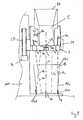
- Figure 1is a schematic side view of a preferred embodiment of the device according to the present invention.
- a disc member 2comprises at least two outlet nozzles 4 which are preferably arranged circumferential to a central axis C of the disc member.
- the disc membercomprises an outlet 3 which is in fluid connection to a coffee mixing chamber 5 which is mounted on the disc member.
- the disc member 2preferably comprises a spray nozzle 8 which is designed to inject a spray A5 towards a receptacle placed beneath the disc member 2.
- the outlet nozzles 4, the spray nozzle 8 and the mixing chamber 5are in fluid connection to liquid supply means 6 of the device.
- the liquid supply meanspreferably comprise a water tank 6a respectively a reservoir suitable for providing a liquid to the device. It should be noted that instead of a reservoir, the device may be connected to a water tap in order to establish a permanent liquid supply.
- the liquid supply meanscomprise a pump 6b which is in connection to the reservoir and which provides liquid to a boiler 6c of the water supply means 6.
- a thermo block or other suitable heating meansmay be provided instead of a boiler.
- the water supply meansare designed for supplying a heating pressurized liquid.
- a by-pass water path 17may be provided in order to by-pass the heating means 6c and thus for providing a pressurized cold water to the outlet nozzles 4 respectively to the spray nozzle 8.
- valve members 23, 24, 25are arranged within the fluid connection between the mixing chamber 5, the outlet nozzles 4 and the spray nozzle 8, valve members 23, 24, 25 are arranged.
- the valve membershave at least an open and a closed position in which a liquid flow from the liquid supply means to the outlet nozzles 4, the spray nozzle 8 or the mixing chamber 5 is enabled or disabled respectively.
- the valve members 23, 24, 25are preferably connected to a control unit 7 which controls the position of the valve members. Accordingly, liquid may be selectively provided to the outlet nozzles 4, the spray nozzle 8 and the mixing chamber 5.
- valve member 23connected between the liquid supply means 6 and the outlet nozzles 4.
- the outlet nozzles 4are in fluid connection to a single tubular member, e.g. tubular member 4a, connected to the valve member 23.
- the tubular member 4amay for example be formed as a circular channel in the disc member 2. Due to the outlet nozzles 4 being in fluid connection to the tubular member 4a, distribution of liquid from the tubular member 4a to the outlet nozzles 4 is enabled.
- the outlet nozzles 4may comprise any means suitable for directing a fluid jet towards the receptacle 13.
- the outlet nozzles 4may protrude to a certain extent from the disc member 2.
- the outlet nozzlesmay as well be formed as an integral part of the disc member, such as for example holes formed in the disc member 2.
- the holescan be of different size to provide different water pressures.
- a liquid supply to the outlet nozzles 4results in a jet of liquid A3, A4 being ejected from the corresponding outlet nozzles 4.
- the outlet nozzlesare preferably arranged at the disc member 2 such that at least one of the fluid jets A3, A4 is directed to a bottom portion 13a of a receptacle 13 placed on a support means 1 beneath the disc member 2.
- at least one of the outlet nozzles 4is arranged such that the ejected fluid jet A4 hits a sidewall portion 13b of the receptacle 13.
- the fluid jet which is directed to a bottom portion 13a of the receptacle 13provides the essential force for dissolving a food substance which is preferably provided in powder form to the receptacle.
- the fluid jet directed to a sidewall portion 13b of the receptacleis able to prevent food substance from sticking to the sidewall of the receptacle.
- the outlet nozzles 4are preferably arranged at a fixed position at the disc member 2.
- adjusting meansmay be provided for adjusting the position of the outlet nozzles 4, 8 and thus, for adjusting the paths of the fluid jets ejected there from.
- the receptacleis preferably placed centrically to the central axis C of the disc member 2. According to this, the ejected fluid jets are directed to the intended portions of the receptacle 13, as already described.
- positioning means 9are provided which enable a guidance of the receptacle toward a correct position of the receptacle.
- the positioning means 9preferably comprise annular grooves 9a, 9b, 9c which are arranged concentrically to a central axis C of the disc member 2.
- an annular ring member 9dmay be placed which preferably can be adjusted to different sizes in order to fit the different grooves 9a, 9b, 9c.
- the ring member 9dprotrudes to a predefined extent from an upper surface la of the support means 1.
- a usermay adjust the ring member 9d to fit in one of the provided grooves 9a, 9b, 9c and thus, to guide a lower portion of the receptacle 13 in order to enable a concentric positioning of the receptacle 13 with respect to the disc member 2.
- the positioning meansmay be any means for supporting a user of the device in positioning the receptacle with respect to the disc member 2.
- the number of grooves interacting with the protruding ring member 9dmay vary from the number indicated in the figure.
- the support means 1are preferably connected to a rotating and lifting device 27 which is connected to a motor 26.
- the motor 26is preferably controlled by the controlling unit 7 of the device in order to enable an operation of the rotating and lifting device 27 during a beverage preparation cycle as indicated by arrows Z1 and Z2 in figure 1 .
- Figure 2relates to a side view of another preferred embodiment of the device according to the present invention.
- the rotating and lifting deviceis connected to the disc member 2 by means of a connection element 29 which is circumferentially arranged at the disc member 2 and which is connected to a rotating and lifting means 27 housed within a housing 100 of the device.
- the rotating and lifting device 27is designed for enabling a lifting and lowering of the disc member with respect of the support means 1 of the device.
- the lifting and rotating means 27enable a rotation of the disc member 2 about a central axis C of the disc member 2.
- the rotating and lifting means 27are preferably connected to a motor 26 such as an electric motor mounted within the housing 100 of the device.
- the motor 26is preferably connected to the control unit 7 of the device.
- the mixing chamber 5comprises an aperture 28 and is thus accessible for a user of the device.
- the aperture 28may be equipped with a lid (not shown) in order to enable an opening and closing of the mixing chamber 5.
- the mixing chamber 5is preferably cylindrically shaped and comprises an outlet 3 at a lower portion thereof. Moreover, at an elevated position within the mixing chamber 5, a water inlet 5b is arranged which is in fluid connection to the liquid supply means by means of a tubular member 5a.
- a coffee based concentrate dosesuch as coffee powder 21 may be provided to the mixing chamber 5 by means of the aperture 28. Then, a liquid, preferably hot pressurized water, is introduced into the mixing chamber 5. Hence, the provided liquid interacts with the coffee powder 21 in order to form a coffee beverage which is dispensed from the mixing chamber 5 by means of the outlet 3.
- the coffee beverageis thus provided to the receptacle 13 which is placed underneath the disc member 2.
- the outlet 3is preferably arranged concentrically to the disc member 2.
- the outlet 3may be equipped with a perforated member 3a for preventing the coffee powder 21 from falling into the receptacle before the interaction of the powder 21 with the liquid.
- the milkis prepared within the cup by means of an in-cup-preparation thereof.
- a food substancesuch as a dry powder may be provided to the receptacle 13 prior to the beverage preparation. Then, liquid in form of fluid jets A1, A2, A3, A4 is provided to the receptacle 13 in order to dissolve the food substance 20 therein.
- the disc member 2preferably comprises four outlet nozzles 4, wherein at least two of the other nozzles A1, A2 are arranged in order to direct a fluid jet to a bottom portion 13a of the receptacle. Moreover, preferably two of the outlet nozzles 4 are arranged in order to provide a fluid jet A3,A4 to an inner side wall portion 13b of the receptacle 13. Hence, effective dissolving of the food substance 20 within the receptacle 13 is obtained.
- the disc member 2is brought to approach an upper rim portion 13c of the receptacle prior to the provision of liquid to the receptacle.
- the pressure of the fluid jets which hit the surface area of the liquid within the receptacle during the beverage preparationis reduced and thus, mixing of the beverage is enhanced.
- the formation of big bubbles due to the impact of the fluid jets and the surface of a liquid within the receptacle 13is reduced.
- the disc member 2 and thus the outlet nozzles 4can be lifted with respect to receptacle 13.
- the disc member 2is preferably rotated about its central axis C by means of the lifting/rotating means 27.
- the fluid jets ejected by the outlet nozzles 4 of the disc member 2are provided to different portions of the receptacle 13 and thus, mixing of the beverage is enhanced.
- the fluid jets provided to a side wall portion 13b of the receptacle 13are provided continuously to an inner circumferential portion of the receptacle 13. Hence, any residual of the food substance which sticks to an inner side wall portion of the receptacle 13 is washed away.
- Control means 7preferably comprise a state machine which enables the control of the liquid supply to the outlet nozzles 4, the spray nozzle 8 and the mixing chamber 5 respectively. Therefore, during a beverage preparation side of a mixed beverage, the control means 7 first provide liquid to the outer nozzles 4 and thus to the receptacle 13 in order to dissolve and eventually froth a food substance provided to the receptacle. Thereby, the amount of liquid provided to the receptacle is preferably controlled by a flow metering device (not shown) connected within the liquid flow path of the liquid supply means 7 and the outlet nozzles 4. Thereby, a user is preferably able to chose the volume of the liquid to be dispensed into the receptacle 13 by means of a manual interface provided at the device (not shown).
- a flow metering deviceis preferably arranged in order to control the amount of liquid provided to the mixing chamber 5.
- a useris preferably enabled by a manual interface provided at the device (not shown) to control the amount of liquid to be provided to the mixing chamber 5.
- the spring nozzle 8may be supplied with liquid after liquid supply to the outlet nozzles 4 has been cut by the control means 7.
- the spray of vapour provided by the spray nozzleis applied to the beverage within the receptacle 13 in order to subdue big bubbles.
- the spray of vapoursupports the formation of small bubbles on the surface of the beverage which is particularly desired for cappuccino type beverages.
- the outlet nozzles 4 and thus the ejected fluid jetsare arranged at a certain angle ⁇ , ⁇ (see figure 1 ) with respect to the central axis C of the disc member 2.
- the angle ⁇preferably differs for each of the outlet nozzles 4 designed to direct a fluid jet A1, A2 to the bottom of the receptacle 13a.
- the angle ⁇preferably differs for each of the outlet nozzles 4 designed to direct a fluid jet A3, -A4 to an inner side wall 13b of the receptacle 13.
- the angles ⁇ , ⁇are between -10 and +10 degrees.
- the values for the angles ⁇ , ⁇may vary without departing from the scope of the invention.
- a fifth outlet nozzle 11is arranged at the disc member 2 and is in fluid connection to the liquid supply means 6.
- said fifth outlet nozzle 11differs in diameter to the other outlet nozzles 4.
- the outlet nozzle 11has a greater diameter in order to provide a bigger amount of a liquid with a lower pressure to the receptacle during the beverage preparation cycle. Accordingly, waiting time for a user of the device is reduced and frothing force of the jet is reduced.
- the outlet nozzle 4is in particular useful for the preparation of tea.
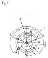
- Figure 3is a bottom view of a preferred embodiment of the disc member 2 housing the outlet nozzles 4 and the outlet of the coffee mixing chamber 3.
- the outlet 3 of the mixing chamber 5is arranged centrically to the centre c1 of the disc member 2.
- the outlet nozzles 4are preferably of the same outlet diameter d4 thus producing fluid jets of the same pressure.
- the outlet diameter d4is preferably between 0.2 and 0.9 mm.
- Said outlet nozzles 4are arranged on the same distance d1 compared to the center c1 of the disc member 2.
- Said distance d1is preferably between 30 and 60 mm.
- the spray nozzle 8is preferably situated at a smaller distance d2 to the center c1 of the disc member 2. Thereby, the distance D2 is preferably between 20 and 50 mm.
- the spray nozzlepreferably ejects a hollow cone spray of vapour with an angle of 60 to 85°.
- the liquid flow of the spray nozzleis preferably between 1.5 and 3ml per second.
- the outlet nozzle 11is of a greater diameter d3 than the outlet nozzles 4 and is preferably arranged at the same distance d1 from the center c1 of the disc member 2.
- the diameter d3is preferably between 1.5 and 4 mm.
- the speed of rotation of the disc member 2is between 0.5 and 1.5 revolutions per second. More preferably, the speed of rotation of the disc member is between 0.8 and 1.2 revolutions per second.
- Figure 4is a top view of a preferred embodiment of a receptacle to be used with the present invention, wherein the impact points of the fluid jets A1, A2, A3, A4 ejected by the outlet nozzles 4 are indicated.
- the outlet of the mixing chamber 5preferably hits the bottom portion 13a of the receptacle 13 at its center C1. Moreover, as indicated by reference numerals A3 and A4, preferably two of the fluid jets provided by the outlet nozzles 4 hit a side wall portion 13b of the receptacle. Thereby, the distance of the impact points of the fluid jets A3, A4 from the center c1 preferably differs.
- the reference numerals A1 and A2refer to impact points of two fluid jets ejected by outlet nozzles 4 which are arranged to hit a bottom portion 13a of the receptacle 13.
- the distance of the impact points A1, A2 from the center c1preferably differ.
- different portions of the bottom portion of the receptacleare hit by fluid jets which results in an improvement of the mixing process.
- the fluid jetsare continuously rotating about the central axis C of the disc member, thereby inducing a swirling motion within the receptacle. Accordingly, enhanced mixing of the beverage to be prepared is enhanced.
- the reference numeral A6denotes the impact point of the additional nozzle 11 which preferably has a greater outlet diameter than the other outlet nozzles.
- the outlet nozzle 11is arranged to direct a fluid jet towards a side wall portion 13b of the receptacle.
Landscapes
- Engineering & Computer Science (AREA)
- Food Science & Technology (AREA)
- Physics & Mathematics (AREA)
- General Physics & Mathematics (AREA)
- Apparatus For Making Beverages (AREA)
- Devices For Dispensing Beverages (AREA)
- Non-Alcoholic Beverages (AREA)
- Table Devices Or Equipment (AREA)
- Beverage Vending Machines With Cups, And Gas Or Electricity Vending Machines (AREA)
Abstract
Description
- The present invention relates to a device and a system for preparing a beverage from a food substance provided in a receptacle. In particular, the invention relates to such a device which enables the preparation of a beverage from a beverage concentrate which is provided to a receptacle by supplying diluent jets to the receptacle.
- It is known to prepare beverages by mixing a beverage concentrate such as a dry powder and a liquid such as cold or hot water. Thereby, the following principle is generally applied for the beverage preparation.
- A beverage concentrate such as a dry powder is introduced into a receptacle such as a coffee or tea cup. Then, the cup is placed below an outlet of a mixing device which introduces at least a stream or jet of water to the cup in order to enable an interaction of the beverage concentrate and the hot water. Accordingly, the beverage concentrate is dissolved and eventually frothed by the hot water in order to prepare a beverage.
- However, the existing beverage preparation devices which make use of the above outlined principle suffer the inconvenience that the beverage concentrate is not fully diluted and thus, residua of the concentrate are present in the prepared beverage. This leads to a non-uniform and thus to a non-inviting appearance of the prepared beverage.
- In addition, during provision of beverage concentrate to a receptacle, parts of the concentrate may stick to the inner side walls of the receptacle and can thus not be fully dissolved in the beverage preparation process.
- Moreover, if the beverage concentrate is not fully dissolved in the liquid provided to the receptacle, the taste of the beverage may vary from the intended beverage taste.
- Hence, particularly for the beverage preparation of hot beverages such as tea or coffee, it is desired to have a reproducible strength respectively concentration of the beverage to be prepared, wherein the concentration of the beverage corresponds to the amount of beverage concentrate provided to the receptacle and does not vary for each preparation.
- Therefore, a device for the preparation of a beverage according to the above stated principle is sought-after, which enables a full dissolution of the whole amount of beverage concentrate provided to the receptacle.
EP 0 060 645 A1 proposes an apparatus for dispensing liquid into a container at a dispensing station in which two or more nozzles are arranged symmetrically around a central axis and are fed with liquid from a reservoir by a pump. Thereby, the nozzles are inclined from the vertical so as to produce a swirling action as the liquid hits the bottom of the container. Accordingly, in-cup dispensing in order to dissolve or disperse solid material placed at the bottom of a container is enabled.- A further device of the prior art is disclosed in
EP-A-1407698 . - Based on the prior art, the present invention aims at providing a device and a method for allowing an efficient beverage preparation on the basis of food concentrate provided to a receptacle which is mixed with hot water supplied by a jet dissolving device.
- The present invention also aims at providing a device and a method for producing mixed drinks which consist of coffee and milk, for example cappuccino or latte macchiato. Thereby, the coffee beverage is preferably prepared separately to the milk beverage in order to enable a full interaction of the different food substances with liquid before the mixing of the different beverage types.
- The present invention enables the preparation of beverages by effective dissolution of powder concentrates with hot water in a very short time.
- Moreover, the present invention enables the production of beverages with an attractive appearance presenting simultaneously small and dense bubbles and a homogeneous dissolution.
- In addition, the present invention enables the preparation of different beverages presenting different types of foam quality or even the absence of foam according to the type of prepared beverage.
- In a first aspect, the present invention relates to a beverage production device for preparing a beverage from a beverage concentrate contained in a receptacle according to
independent claim 1. - The outlet nozzles of the disc member are arranged at different angles with respect to a central axis of the disc member respectively an axis perpendicular to a bottom plane of the receptacle. The angles at which the outlet nozzles are arranged with respect to the axis perpendicular to a bottom plane of the receptacle preferably have a value between -10° and +10°. Accordingly, the fluid jets are not concentrated to one single point of intersection but are rather applied to different portions of the receptacle.
- The two fluid jets are directed towards the bottom portion of the receptacle in order to provide the essential force for dissolving the portioned food substance provided to the receptacle. The other two fluid jets are directed towards an inner sidewall portion of the receptacle in order to avoid the risk of having the food substance introduced into the receptacle on the sidewalls of the receptacle. In addition, the dissolution of the food substance which may flow on top of the liquid beverage during the preparation is improved.
- The disc member and the support means of the device are configured for being moved vertically to each other. Hence, during the beverage preparation process, dissolving or dispersion of the food substance is improved as the fluid jets ejected by the outlet nozzles are directed towards different portions of the receptacle during the beverage preparation. Moreover, any remaining food substance sticking to the side wall portions of the receptacle can be washed away due to the lifting respectively lowering movement.
- In a preferred embodiment, liquid supply means are connected to the outlet nozzles. These liquid supply means are preferably designed to supply a pressurized liquid to the outlet nozzles. Accordingly, the liquid supply means preferably comprise a pump which is connected to a liquid supply such as a water reservoir or a water tap.
- Moreover, the liquid supply means preferably comprise a boiler or a thermo-block suitable for heating the liquid provided by the reservoir. Accordingly, a heated pressurized liquid is provided to the outlet nozzles by the supply means.
- With the device according to the present invention, it is possible to introduce a diluent such as cold or hot water into the receptacle to which a beverage concentrate has been introduced, in order to dissolve and eventually froth the concentrate. Thereby, the beverage concentrate is preferably a dry powder. Said powder may as well be a powder comprising milk components.
- Due to the mixing of the food substance within the receptacle, no additional mixing chamber is necessary. Moreover, neither the mixing chamber nor another part of the beverage machine is contaminated by a bacteria sensitive fluid which results in a very hygienic beverage preparation.
- In a preferred embodiment, the outlet nozzles of the disc member differ in their diameter which results in a different pressure of the fluid jets ejected by the corresponding outlet nozzle. Accordingly, the pressure of the ejected fluid jets can be adjusted for different kinds of beverages to be prepared by the device according to the invention.
- In a preferred embodiment, the device further comprises control means. Said control means are preferably designed to selectively provide liquid from the liquid supply means to the outlet nozzles.
- In a preferred embodiment, at least one additional outlet nozzle of bigger outlet diameter compared to the other outlet nozzles is provided at the disc member. Hence, a larger amount of liquid at low pressure can be provided to the receptacle, compared to the case wherein a smaller outlet diameter nozzle is applied. Accordingly, the preparation of the beverage is accelerated which reduces the waiting time for a user of the device. Besides, the liquid being injected at low pressure, it can be used for the preparation of a beverage without creation of froth above, which is the case for the preparation of tea beverages for example.
- In a preferred embodiment, the disc member further comprises a spray nozzle which is designed to provide a spray of liquid to the receptacle. The spray nozzle is preferably selectively supplied with liquid from the liquid supply means. Accordingly, the spray nozzle can be operated independently of the outlet nozzles of the disc member. The spray nozzle is preferably used for the production of small bubbles on top of a beverage to be prepared such as a cappuccino. Effectively the spray nozzle may be used for preventing the formation of big bubbles on top of the beverage because its interaction with the big bubbles created by the jets issued from the nozzles lead to their disappearance.
- The disc member and the support means of the device are preferably configured for being moved relatively in rotation to each other. Hence, during the beverage preparation process, dissolving or dispersion of the food substance is improved as the fluid jets ejected by the outlet nozzles are directed towards different portions of the receptacle during the beverage preparation. Moreover, any remaining food substance sticking to the side wall portions of the receptacle can be washed away due to rotating movement.
- Preferably, the disc member is connected to lifting means which enable a relative vertical movement of the disc member and the support means. Moreover, the disc member is preferably connected to a rotary drive which enables the rotation of the disc member about its central axis. Thereby, the rotary drive and the lifting means can be operated independently of each other.
- The support means of the device preferably comprise positioning means for enabling a correct position of the receptacle with respect to the disc member. In particular, a centred positioning of the receptacle with respect to the disc member is desired in order to enable a correct positioning of the fluid jets ejected by the outlet nozzles with respect to the inner side wall and bottom portions of the receptacle.
- The positioning means may be a protruding annular frame which can be connected to a base portion of the support means in order to enclose a lower portion of the receptacle. Preferably, the support means can be adjusted to different sizes and designs of receptacles. Accordingly, a receptacle can be correctly positioned with respect to the outlet nozzles in order to enhance the dissolving or dispersion of the food concentrate.
- It should be understood that the support means may be any means which enable an interaction between the support means and the receptacle in order to enable a correct positioning and in particular a concentric position of the receptacle with respect to the disc member.
- For example, the support means may be magnetic means arranged at the centre of the support means which are able to interact with a dedicated receptacle at least partially made of ferro-magnetic material such as to interact with the magnetic means of the support means. Accordingly, a concentric positioning of the receptacle with respect to the support means and thus with respect to the disc member is facilitated.
- The receptacle to be used with the device according to the present invention is preferably of frustro-conical shape. The sidewalls of the container can be straight or angled without affecting the performance of the mixing of the jets. Preferably the sidewall of the receptacle is slightly angled in a conventional manner such as that used for paper or styrofoam coffee cups. Thus the container may have an inclined sidewall of from 1 to 15 degrees with respect to a symmetrical axis of the receptacle. Thereby, the side wall is preferably straight, i.e. the side wall is constantly inclined at the same angle with respect to the symmetrical axis of the receptacle. However, the side wall may as well be slightly rounded, i.e. the side wall of the receptacle may be of convex or concave shape. The receptacle has preferably a volume between 50 and 300 ml.
- In a preferred embodiment, the control means of the device comprise a state machine which is designed to control the supply of liquid to the outlet nozzles of the disc member with respect to an accumulated volume of liquid dispensed from the supply means. Therefore, the supply means preferably comprise a flow meter which is able to detect an accumulated volume of the dispensed liquid for each beverage preparation cycle. According to this embodiment, the control means may open or close the outlet nozzles of the disc member with respect to a predefined time or an accumulated volume of liquid provided by the liquid supply means.
- Moreover, the disc member can comprise an outlet nozzle in connection with a coffee mixing chamber for injecting coffee into the receptacle. Said coffee mixing chamber is preferably accessible from the outside of the device. Hence, if liquid provided by the liquid supply means interacts with the coffee substance provided to the coffee mixing chamber, a coffee beverage is prepared which can then be provided to the receptacle by means of the outlet of the disc member.
- This is in particular advantageous for the preparation of mixed drinks such as latte macchiato or cappuccino, since the different beverage concentrates do not have to be mixed in one single mixing chamber. Accordingly, the coffee mixing chamber can be used for the preparation of coffee beverages only and thus, does not have to be cleaned after each beverage preparation cycle like for a bacteria sensitive fluid.
- In a further aspect, the present invention relates to a method for the preparation of a beverage from a food substance according to independent claim 9.
- Preferably, the method further comprises the steps of providing a coffee extract or coffee powder to a mixing chamber connected to the liquid supply means and discharging said the resulting coffee beverage to the receptacle by means of an outlet at the disc member.
- Thereby, the receptacle and the disc member are preferably moved rotationally in relation to each other during the preparation of the beverage. Hence, as the fluid jets are directed to different portions of the receptacle, effective dissolving or dispersion of the beverage concentrate provided to the receptacle is obtained.
- Moreover, the outlet nozzles are preferably selectively provided with liquid from the liquid supply means, dependent on the accumulated volume of liquid provided to the outlet nozzles. According to this, it is for example possible, to open or close a particular outlet nozzle at a predefined stage of the beverage preparation. This may be for example be useful for the preparation of tea at which an outlet nozzle which provides a spray to the receptacle is opened for a predefined set of time at the end of the beverage preparation process. Hence, due to said spray ejected by the outlet nozzle deformation of big bubbles at the top of the beverage can be subdued.
- Furthermore, in a preferred embodiment, the outlet nozzles are brought to approach a rim portion of the receptacle prior to the preparation of the beverage. Hence, an increase of pressure of the fluid jets which hit the surface of the beverage is obtained and thus, mixing of the beverage is enhanced. During the filling of the receptacle the outlet nozzles respectively the disc member is preferably rotated as already described.
- The beverage concentrate is preferably selected in the list of milk or milk-based powder, tea powder and chocolate based powder.
- The receptacle presents preferably a frustoconical shape.
- Further features, advantages and objects of the present invention will become apparent for the skilled person when reading the following detailed description of embodiments of the present invention, when taken in conjunction with the figures of the enclosed drawings.
- Fig. 1
- shows a schematic side view of a preferred embodiment of the device according to the present invention;
- Fig. 2
- shows a side view of another preferred embodiment of the device according to the present invention.
- Fig. 3
- shows a bottom view of a preferred embodiment of the disc member housing the outlet nozzles and the outlet of the coffee mixing chamber.
- Fig. 4
- shows a top view of a preferred embodiment of a receptacle to be used with the present invention, wherein the impact points of the fluid jets ejected by the outlet nozzles and the outlet of the coffee mixing chamber are indicated.
Figure 1 is a schematic side view of a preferred embodiment of the device according to the present invention.- As can be seen in
figure 1 , adisc member 2 comprises at least twooutlet nozzles 4 which are preferably arranged circumferential to a central axis C of the disc member. In addition, the disc member comprises anoutlet 3 which is in fluid connection to acoffee mixing chamber 5 which is mounted on the disc member. - The
disc member 2 preferably comprises aspray nozzle 8 which is designed to inject a spray A5 towards a receptacle placed beneath thedisc member 2. - The outlet nozzles 4, the
spray nozzle 8 and the mixingchamber 5 are in fluid connection to liquid supply means 6 of the device. - The liquid supply means preferably comprise a water tank 6a respectively a reservoir suitable for providing a liquid to the device. It should be noted that instead of a reservoir, the device may be connected to a water tap in order to establish a permanent liquid supply.
- The liquid supply means comprise a pump 6b which is in connection to the reservoir and which provides liquid to a boiler 6c of the water supply means 6. Thereby, instead of a boiler, a thermo block or other suitable heating means may be provided. According to this embodiment, the water supply means are designed for supplying a heating pressurized liquid.
- In a preferred embodiment however, a by-pass water path 17 (not shown) may be provided in order to by-pass the heating means 6c and thus for providing a pressurized cold water to the
outlet nozzles 4 respectively to thespray nozzle 8. - The fluid connection between the liquid supply means 6 and the
outlet nozzles 4 respectively thespray nozzle 8 and the mixingchamber 5 is established by means oftubular members 4a, 5a, 8a which are schematically shown infigure 1 . - Within the fluid connection between the mixing
chamber 5, theoutlet nozzles 4 and thespray nozzle 8,valve members outlet nozzles 4, thespray nozzle 8 or the mixingchamber 5 is enabled or disabled respectively. Thereby, thevalve members outlet nozzles 4, thespray nozzle 8 and the mixingchamber 5. - However, it may as well be possible to have only one valve member,
e.g. valve member 23, connected between the liquid supply means 6 and theoutlet nozzles 4. Thereby, theoutlet nozzles 4 are in fluid connection to a single tubular member, e.g.tubular member 4a, connected to thevalve member 23. Thetubular member 4a may for example be formed as a circular channel in thedisc member 2. Due to theoutlet nozzles 4 being in fluid connection to thetubular member 4a, distribution of liquid from thetubular member 4a to theoutlet nozzles 4 is enabled. - It should be understood that the
outlet nozzles 4 may comprise any means suitable for directing a fluid jet towards thereceptacle 13. The outlet nozzles 4 may protrude to a certain extent from thedisc member 2. However, the outlet nozzles may as well be formed as an integral part of the disc member, such as for example holes formed in thedisc member 2. The holes can be of different size to provide different water pressures. - As can be seen in
figure 1 , a liquid supply to theoutlet nozzles 4 results in a jet of liquid A3, A4 being ejected from thecorresponding outlet nozzles 4. Thereby, the outlet nozzles are preferably arranged at thedisc member 2 such that at least one of the fluid jets A3, A4 is directed to abottom portion 13a of areceptacle 13 placed on a support means 1 beneath thedisc member 2. Moreover, at least one of theoutlet nozzles 4 is arranged such that the ejected fluid jet A4 hits asidewall portion 13b of thereceptacle 13. Thereby, the fluid jet which is directed to abottom portion 13a of thereceptacle 13 provides the essential force for dissolving a food substance which is preferably provided in powder form to the receptacle. Moreover, the fluid jet directed to asidewall portion 13b of the receptacle is able to prevent food substance from sticking to the sidewall of the receptacle. - In a preferred embodiment, the
outlet nozzles 4 are preferably arranged at a fixed position at thedisc member 2. However, adjusting means may be provided for adjusting the position of theoutlet nozzles - The receptacle is preferably placed centrically to the central axis C of the
disc member 2. According to this, the ejected fluid jets are directed to the intended portions of thereceptacle 13, as already described. - In order to enable a correct positioning of the
receptacle 13 with respect to thedisc member 2 positioning means 9 are provided which enable a guidance of the receptacle toward a correct position of the receptacle. - The positioning means 9 preferably comprise annular grooves 9a, 9b, 9c which are arranged concentrically to a central axis C of the
disc member 2. Therein, anannular ring member 9d may be placed which preferably can be adjusted to different sizes in order to fit the different grooves 9a, 9b, 9c. Hence, thering member 9d protrudes to a predefined extent from an upper surface la of the support means 1. Accordingly, dependent on the size of thereceptacle 13 to be used with the present device, a user may adjust thering member 9d to fit in one of the provided grooves 9a, 9b, 9c and thus, to guide a lower portion of thereceptacle 13 in order to enable a concentric positioning of thereceptacle 13 with respect to thedisc member 2. - It should be understood that the positioning means may be any means for supporting a user of the device in positioning the receptacle with respect to the
disc member 2. Moreover, the number of grooves interacting with the protrudingring member 9d may vary from the number indicated in the figure. - The support means 1 are preferably connected to a rotating and lifting
device 27 which is connected to amotor 26. Thereby, themotor 26 is preferably controlled by the controlling unit 7 of the device in order to enable an operation of the rotating and liftingdevice 27 during a beverage preparation cycle as indicated by arrows Z1 and Z2 infigure 1 . Figure 2 relates to a side view of another preferred embodiment of the device according to the present invention.- Therein, the rotating and lifting device is connected to the
disc member 2 by means of aconnection element 29 which is circumferentially arranged at thedisc member 2 and which is connected to a rotating and lifting means 27 housed within ahousing 100 of the device. Thereby, the rotating and liftingdevice 27 is designed for enabling a lifting and lowering of the disc member with respect of the support means 1 of the device. Moreover, the lifting androtating means 27 enable a rotation of thedisc member 2 about a central axis C of thedisc member 2. The rotating and lifting means 27 are preferably connected to amotor 26 such as an electric motor mounted within thehousing 100 of the device. Themotor 26 is preferably connected to the control unit 7 of the device. - As shown in
figure 2 , the mixingchamber 5 comprises anaperture 28 and is thus accessible for a user of the device. Thereby, theaperture 28 may be equipped with a lid (not shown) in order to enable an opening and closing of the mixingchamber 5. - The mixing
chamber 5 is preferably cylindrically shaped and comprises anoutlet 3 at a lower portion thereof. Moreover, at an elevated position within the mixingchamber 5, a water inlet 5b is arranged which is in fluid connection to the liquid supply means by means of a tubular member 5a. - Hence, for the preparation of a coffee beverage, a coffee based concentrate dose such as coffee powder 21 may be provided to the mixing
chamber 5 by means of theaperture 28. Then, a liquid, preferably hot pressurized water, is introduced into the mixingchamber 5. Hence, the provided liquid interacts with the coffee powder 21 in order to form a coffee beverage which is dispensed from the mixingchamber 5 by means of theoutlet 3. - The coffee beverage is thus provided to the
receptacle 13 which is placed underneath thedisc member 2. Thereby, theoutlet 3 is preferably arranged concentrically to thedisc member 2. - The
outlet 3 may be equipped with a perforated member 3a for preventing the coffee powder 21 from falling into the receptacle before the interaction of the powder 21 with the liquid. - Moreover, for the preparation of a mixed beverage such as a cappuccino or latte macchiato which basically consists of coffee and milk, the milk is prepared within the cup by means of an in-cup-preparation thereof.
- Accordingly, a food substance such as a dry powder may be provided to the
receptacle 13 prior to the beverage preparation. Then, liquid in form of fluid jets A1, A2, A3, A4 is provided to thereceptacle 13 in order to dissolve thefood substance 20 therein. - For the beverage preparation within the
receptacle 13, thedisc member 2 preferably comprises fouroutlet nozzles 4, wherein at least two of the other nozzles A1, A2 are arranged in order to direct a fluid jet to abottom portion 13a of the receptacle. Moreover, preferably two of theoutlet nozzles 4 are arranged in order to provide a fluid jet A3,A4 to an innerside wall portion 13b of thereceptacle 13. Hence, effective dissolving of thefood substance 20 within thereceptacle 13 is obtained. - In a preferred embodiment, the
disc member 2 is brought to approach anupper rim portion 13c of the receptacle prior to the provision of liquid to the receptacle. Hence, the pressure of the fluid jets which hit the surface area of the liquid within the receptacle during the beverage preparation is reduced and thus, mixing of the beverage is enhanced. Moreover, the formation of big bubbles due to the impact of the fluid jets and the surface of a liquid within thereceptacle 13 is reduced. - With increasing filling level of the liquid within the
receptacle 13, thedisc member 2 and thus theoutlet nozzles 4 can be lifted with respect toreceptacle 13. Thereby, thedisc member 2 is preferably rotated about its central axis C by means of the lifting/rotatingmeans 27. According to this, the fluid jets ejected by theoutlet nozzles 4 of thedisc member 2 are provided to different portions of thereceptacle 13 and thus, mixing of the beverage is enhanced. In particular, the fluid jets provided to aside wall portion 13b of thereceptacle 13 are provided continuously to an inner circumferential portion of thereceptacle 13. Hence, any residual of the food substance which sticks to an inner side wall portion of thereceptacle 13 is washed away. - Control means 7 (see
figure 1 ) preferably comprise a state machine which enables the control of the liquid supply to theoutlet nozzles 4, thespray nozzle 8 and the mixingchamber 5 respectively. Therefore, during a beverage preparation side of a mixed beverage, the control means 7 first provide liquid to theouter nozzles 4 and thus to thereceptacle 13 in order to dissolve and eventually froth a food substance provided to the receptacle. Thereby, the amount of liquid provided to the receptacle is preferably controlled by a flow metering device (not shown) connected within the liquid flow path of the liquid supply means 7 and theoutlet nozzles 4. Thereby, a user is preferably able to chose the volume of the liquid to be dispensed into thereceptacle 13 by means of a manual interface provided at the device (not shown). - After the liquid supply to the
receptacle 13 by means of theoutlet nozzles 4 is stopped, the liquid supply to the mixingchamber 5 by means of the inlet 5b is enabled. Accordingly, any food substance such as dry coffee powder provided to the mixingchamber 3 interacts with the provided liquid and is thus dispensed through theoutlet 3 intoreceptacle 13. Between the inlet 5b and the liquid supply means, a flow metering device is preferably arranged in order to control the amount of liquid provided to the mixingchamber 5. Thereby, a user is preferably enabled by a manual interface provided at the device (not shown) to control the amount of liquid to be provided to the mixingchamber 5. - In addition, the
spring nozzle 8 may be supplied with liquid after liquid supply to theoutlet nozzles 4 has been cut by the control means 7. Hence, the spray of vapour provided by the spray nozzle is applied to the beverage within thereceptacle 13 in order to subdue big bubbles. Furthermore, the spray of vapour supports the formation of small bubbles on the surface of the beverage which is particularly desired for cappuccino type beverages. - In order to enable an efficient mixing of the beverage within the
receptacle 13, theoutlet nozzles 4 and thus the ejected fluid jets are arranged at a certain angle α, β (seefigure 1 ) with respect to the central axis C of thedisc member 2. Thereby, the angle α preferably differs for each of theoutlet nozzles 4 designed to direct a fluid jet A1, A2 to the bottom of thereceptacle 13a. Moreover, the angle β preferably differs for each of theoutlet nozzles 4 designed to direct a fluid jet A3, -A4 to aninner side wall 13b of thereceptacle 13. In a preferred embodiment, the angles α, β are between -10 and +10 degrees. - In a preferred embodiment, a
first nozzle 4 is arranged in parallel to the central axis C (β = 0). Moreover, a second outlet nozzle is arranged at an angle of β = -10° to the central axis c. In addition, athird outlet nozzle 4 is arranged at an angle α of 3° to the central axis c. A fourth outlet nozzle is arranged at an angle α of 10°. The values for the angles α, β may vary without departing from the scope of the invention. - In a preferred embodiment, a
fifth outlet nozzle 11 is arranged at thedisc member 2 and is in fluid connection to the liquid supply means 6. Preferably, saidfifth outlet nozzle 11 differs in diameter to theother outlet nozzles 4. In particular, theoutlet nozzle 11 has a greater diameter in order to provide a bigger amount of a liquid with a lower pressure to the receptacle during the beverage preparation cycle. Accordingly, waiting time for a user of the device is reduced and frothing force of the jet is reduced. Theoutlet nozzle 4 is in particular useful for the preparation of tea. Figure 3 is a bottom view of a preferred embodiment of thedisc member 2 housing theoutlet nozzles 4 and the outlet of thecoffee mixing chamber 3.- As can be seen in the figure, the
outlet 3 of the mixingchamber 5 is arranged centrically to the centre c1 of thedisc member 2. - The outlet nozzles 4 are preferably of the same outlet diameter d4 thus producing fluid jets of the same pressure. The outlet diameter d4 is preferably between 0.2 and 0.9 mm.
Said outlet nozzles 4 are arranged on the same distance d1 compared to the center c1 of thedisc member 2. Said distance d1 is preferably between 30 and 60 mm.- The
spray nozzle 8 is preferably situated at a smaller distance d2 to the center c1 of thedisc member 2. Thereby, the distance D2 is preferably between 20 and 50 mm. The spray nozzle preferably ejects a hollow cone spray of vapour with an angle of 60 to 85°. The liquid flow of the spray nozzle is preferably between 1.5 and 3ml per second. - The
outlet nozzle 11 is of a greater diameter d3 than theoutlet nozzles 4 and is preferably arranged at the same distance d1 from the center c1 of thedisc member 2. The diameter d3 is preferably between 1.5 and 4 mm. - Preferably, the speed of rotation of the
disc member 2 is between 0.5 and 1.5 revolutions per second. More preferably, the speed of rotation of the disc member is between 0.8 and 1.2 revolutions per second. Figure 4 is a top view of a preferred embodiment of a receptacle to be used with the present invention, wherein the impact points of the fluid jets A1, A2, A3, A4 ejected by theoutlet nozzles 4 are indicated.- The outlet of the mixing
chamber 5 preferably hits thebottom portion 13a of thereceptacle 13 at its center C1. Moreover, as indicated by reference numerals A3 and A4, preferably two of the fluid jets provided by theoutlet nozzles 4 hit aside wall portion 13b of the receptacle. Thereby, the distance of the impact points of the fluid jets A3, A4 from the center c1 preferably differs. - In addition, the reference numerals A1 and A2 refer to impact points of two fluid jets ejected by
outlet nozzles 4 which are arranged to hit abottom portion 13a of thereceptacle 13. Thereby, as indicated infigure 4 , the distance of the impact points A1, A2 from the center c1 preferably differ. Accordingly, different portions of the bottom portion of the receptacle are hit by fluid jets which results in an improvement of the mixing process. Moreover, due to the rotation of thedisc member 2, the fluid jets are continuously rotating about the central axis C of the disc member, thereby inducing a swirling motion within the receptacle. Accordingly, enhanced mixing of the beverage to be prepared is enhanced. - The reference numeral A6 denotes the impact point of the
additional nozzle 11 which preferably has a greater outlet diameter than the other outlet nozzles. Preferably, theoutlet nozzle 11 is arranged to direct a fluid jet towards aside wall portion 13b of the receptacle. - Although the present invention has been described with reference to preferred embodiments thereof, many modifications and alternations may be made by a person having ordinary skill in the art without departing from the scope of this invention which is defined by the appended claims.
Claims (14)
- A beverage production device for preparing a beverage from a beverage concentrate contained in a receptacle, comprising
a receptacle,
a support means (1) for supporting the receptacle (13),
a disc member (2) arranged vertically to the support means, the disc member (2) comprising at least four outlet nozzles (4) for injecting a fluid jet (A) into the receptacle (13),
liquid supply means (6) connected to the outlet nozzles (4),
wherein at least two of the outlet nozzles (4) are designed to direct a fluid jet (A3,A4) to an inner side wall (13b) of the receptacle (13) and said outlet nozzles (4) are arranged at different angles (α) with respect to a central axis (C) of the disc member (2), and
wherein at least two of the outlet nozzles (4) are designed to direct a fluid jet (A1, A2) to the bottom of the receptacle (13a) and said outlet nozzles (4) are arranged at different angles (β) with respect to a central axis (C) of the disc member (2),
wherein the disc member (2) and the support means (1) are configured for being moved vertically to each other. - A beverage production device according to claim 1,
wherein the disc member (2) further comprises a spray nozzle (8) which is designed to provide a spray to the receptacle (13). - A beverage production device according to any of the preceding claims,
wherein the angles (α, β) have a value between -10° and +10°. - A beverage production device according to any of the preceding claims,
wherein the disc member (2) and the support means (1) are configured for being moved relatively in rotation to each other. - A beverage production device according to any of the preceding claims,
wherein the support means (1) comprise positioning means (9) for enabling a centred positioning of the receptacle with respect to the disc member. - A beverage production device according to claim 5,
wherein the positioning means (9) comprise an annular member (9d) protruding from an upper surface (1a) of the support means (1) and which is adaptable to different receptacle sizes. - A beverage production device according to any of the preceding claims,
wherein the disc member (2) comprises an outlet nozzle (3) in connection with a coffee mixing chamber (5) for injecting coffee into the receptacle (13). - A beverage production device according to claim 7,
wherein the device further comprises control means (7) comprising a state machine which is designed to control the supply of liquid to the mixing chamber (5) and the outlet nozzles (4) of the disc member (2) with respect to an accumulated volume of liquid dispensed from the supply means (6). - A method for the preparation of a beverage from a food substance, comprising the steps of:- providing a beverage concentrate (20) to a receptacle (13),- directing at least two fluid jets (A1, A2) to an inner bottom portion (13a) and at least two fluid jets (A3,A4) to an inner side wall portion (13b) of the receptacle by means of outlet nozzles (4) provided at a disc member (2) arranged vertically to the receptacle (13),wherein the at least two fluid jets (A1, A2) directed to the inner bottom portion (13a) of the receptacle and respectively the at least two fluid jets (A3,A4) directed to the inner side wall portion (13a) of the receptacle are arranged at different angles (α, β) with respect to a central axis (C) of the disc member (2), the method further comprising the step of- moving the receptacle (13) and the disc member (2) vertically to each other during the preparation of the beverage
- A method according to claim 9,
the method further comprising the steps of providing a coffee extract or coffee powder (21) to a mixing chamber (5) connected to the liquid supply means (6) and discharging said the resulting coffee beverage to the receptacle (13) by means of an outlet (3) at the disc member (2). - A method according to claim 9 or 10,
wherein the receptacle (13) and the disc member (2) are moved rotationally to each other during the preparation of the beverage. - A method according to any of claims 9 to 11,
wherein the disc member (2) is brought to approach a rim portion (13c) of the receptacle (13) prior to the preparation of the beverage and is rotated during filling of the receptacle. - A method according to any of claims 9 to 12,
wherein the beverage concentrate is selected in the list of milk or milk-based powder, tea powder and chocolate based powder. - A method according to any of claims 9 to 13,
wherein the receptacle presents a frustoconical shape.
Priority Applications (25)
| Application Number | Priority Date | Filing Date | Title |
|---|---|---|---|
| ES08164987TES2362955T3 (en) | 2008-09-24 | 2008-09-24 | DEVICE FOR THE PREPARATION OF A DRINK WITHIN A CUP. |
| DE602008006077TDE602008006077D1 (en) | 2008-09-24 | 2008-09-24 | Device for preparing a drink in a cup |
| EP08164987AEP2168468B1 (en) | 2008-09-24 | 2008-09-24 | Device for In-cup-preparation of a beverage |
| AT08164987TATE504230T1 (en) | 2008-09-24 | 2008-09-24 | DEVICE FOR PREPARING A DRINK IN A CUP |
| JP2011527358AJP5474071B2 (en) | 2008-09-24 | 2009-09-22 | Equipment for in-cup preparation of beverages |
| US13/120,612US9918584B2 (en) | 2008-09-24 | 2009-09-22 | Device for in-cup-preparation of a beverage |
| CA2738020ACA2738020C (en) | 2008-09-24 | 2009-09-22 | Device for in-cup preparation of a beverage |
| NZ591887ANZ591887A (en) | 2008-09-24 | 2009-09-22 | Device for in-cup-preparation of a beverage with two nozzles directed to the bottom aof a receptacle and two nozzles directed to the side wall |
| RU2011116214/12ARU2520013C2 (en) | 2008-09-24 | 2009-09-22 | Device for preparation of beverage in cup |
| BRPI0919244ABRPI0919244A2 (en) | 2008-09-24 | 2009-09-22 | device for cup preparation of a drink |
| EP09783294AEP2348931B1 (en) | 2008-09-24 | 2009-09-22 | Device for in-cup-preparation of a beverage |
| PCT/EP2009/062279WO2010034722A1 (en) | 2008-09-24 | 2009-09-22 | Device for in-cup-preparation of a beverage |
| MX2011003171AMX2011003171A (en) | 2008-09-24 | 2009-09-22 | Device for in-cup-preparation of a beverage. |
| CN201410046015.1ACN103815788B (en) | 2008-09-24 | 2009-09-22 | Apparatus for in-cup preparation of beverages |
| NZ601707ANZ601707A (en) | 2008-09-24 | 2009-09-22 | Device for in-cup-preparation of a beverage |
| AU2009295921AAU2009295921B2 (en) | 2008-09-24 | 2009-09-22 | Device for in-cup-preparation of a beverage |
| CN200980146600.6ACN102223828B (en) | 2008-09-24 | 2009-09-22 | Apparatus for in-cup preparation of beverages |
| ES09783294TES2391615T3 (en) | 2008-09-24 | 2009-09-22 | Device for the preparation of a drink, in the cup |
| CA2915290ACA2915290C (en) | 2008-09-24 | 2009-09-22 | Device for in-cup-preparation of a beverage |
| TW098132369ATW201029611A (en) | 2008-09-24 | 2009-09-24 | Device for in-cup preparation of a beverage |
| HK10108942.0AHK1142251B (en) | 2010-09-20 | Device for in-cup-preparation of a beverage | |
| CL2011000637ACL2011000637A1 (en) | 2008-09-24 | 2011-03-24 | Beverage production device, for preparing a beverage from a beverage concentrate contained in a container, comprising support means for supporting the container, a base member positioned vertically towards the support means, with the base member comprising minus four outlet nozzles; and method to prepare a drink. |
| ZA2011/03052AZA201103052B (en) | 2008-09-24 | 2011-04-21 | Device for in-cup-preparation of a beverage |
| JP2013261213AJP5787968B2 (en) | 2008-09-24 | 2013-12-18 | Method for preparing beverages from food substances |
| US15/898,868US10548429B2 (en) | 2008-09-24 | 2018-02-19 | Device for in-cup preparation of a beverage |
Applications Claiming Priority (1)
| Application Number | Priority Date | Filing Date | Title |
|---|---|---|---|
| EP08164987AEP2168468B1 (en) | 2008-09-24 | 2008-09-24 | Device for In-cup-preparation of a beverage |
Publications (2)
| Publication Number | Publication Date |
|---|---|
| EP2168468A1 EP2168468A1 (en) | 2010-03-31 |
| EP2168468B1true EP2168468B1 (en) | 2011-04-06 |
Family
ID=40342994
Family Applications (2)
| Application Number | Title | Priority Date | Filing Date |
|---|---|---|---|
| EP08164987AActiveEP2168468B1 (en) | 2008-09-24 | 2008-09-24 | Device for In-cup-preparation of a beverage |
| EP09783294ANot-in-forceEP2348931B1 (en) | 2008-09-24 | 2009-09-22 | Device for in-cup-preparation of a beverage |
Family Applications After (1)
| Application Number | Title | Priority Date | Filing Date |
|---|---|---|---|
| EP09783294ANot-in-forceEP2348931B1 (en) | 2008-09-24 | 2009-09-22 | Device for in-cup-preparation of a beverage |
Country Status (17)
| Country | Link |
|---|---|
| US (2) | US9918584B2 (en) |
| EP (2) | EP2168468B1 (en) |
| JP (2) | JP5474071B2 (en) |
| CN (2) | CN102223828B (en) |
| AT (1) | ATE504230T1 (en) |
| AU (1) | AU2009295921B2 (en) |
| BR (1) | BRPI0919244A2 (en) |
| CA (2) | CA2915290C (en) |
| CL (1) | CL2011000637A1 (en) |
| DE (1) | DE602008006077D1 (en) |
| ES (2) | ES2362955T3 (en) |
| MX (1) | MX2011003171A (en) |
| NZ (2) | NZ591887A (en) |
| RU (1) | RU2520013C2 (en) |
| TW (1) | TW201029611A (en) |
| WO (1) | WO2010034722A1 (en) |
| ZA (1) | ZA201103052B (en) |
Families Citing this family (43)
| Publication number | Priority date | Publication date | Assignee | Title |
|---|---|---|---|---|
| JP2013535242A (en) | 2010-07-12 | 2013-09-12 | ネステク ソシエテ アノニム | Secure cup support for beverage machines |
| CA2843759A1 (en)* | 2010-09-08 | 2012-03-15 | Scanomat A/S | A brewing device |
| CN102397008A (en)* | 2011-01-13 | 2012-04-04 | 九阳股份有限公司 | Equipment for preparing beverages and preparation method thereof |
| GB2487393A (en)* | 2011-01-19 | 2012-07-25 | Kraft Foods R & D Inc | Kit, method and apparatus for preparing a chocolate beverage |
| CA2830768A1 (en)* | 2011-03-30 | 2012-10-04 | Nestec S.A. | Beverage dispenser with improved nozzles assembly |
| US20140083300A1 (en)* | 2011-05-27 | 2014-03-27 | Nestec S.A. | Beverage dispenser with removable nozzle rotating module |
| MX2014002589A (en)* | 2011-09-06 | 2014-11-21 | Nestec Sa | Method for producing beverages. |
| JP6113169B2 (en) | 2011-09-20 | 2017-04-12 | ネステク ソシエテ アノニム | Dispenser for hot and cold beverages |
| AU2012311571A1 (en) | 2011-09-22 | 2014-03-27 | Nestec S.A. | Cup support and dispensing device |
| WO2013063717A1 (en)* | 2011-11-01 | 2013-05-10 | Jiang Wende | Apparatus for formulating powdery substances |
| JP6272772B2 (en)* | 2011-11-23 | 2018-01-31 | スターバックス・コーポレイション | Beverage extraction apparatus, system and method |
| WO2014096017A1 (en) | 2012-12-21 | 2014-06-26 | Nestec S.A. | Food or beverage production system |
| WO2015077237A2 (en) | 2013-11-20 | 2015-05-28 | Starbucks Corporation D/B/A Starbucks Coffee Company | Cooking system power management |
| WO2015091027A1 (en) | 2013-12-20 | 2015-06-25 | Nestec S.A. | Process for preparing foamed milk |
| WO2015091026A1 (en) | 2013-12-20 | 2015-06-25 | Nestec S.A. | Process for preparing asoluble milk ingredient with improved foaming properties |
| KR101489687B1 (en)* | 2014-01-09 | 2015-02-04 | 강동진 | Coffee drip machine |
| US20170172338A1 (en)* | 2014-02-14 | 2017-06-22 | Remington Designs, Llc | Beverage brewer and related methods for brewing beverages |
| WO2015173285A1 (en) | 2014-05-13 | 2015-11-19 | Nestec S.A. | Container and code of system for preparing a beverage or foodstuff |
| CN106470576B (en) | 2014-06-30 | 2019-05-28 | 皇家飞利浦有限公司 | Coffee dispensing apparatus |
| EP3232873B1 (en)* | 2014-12-15 | 2019-01-30 | Koninklijke Douwe Egberts B.V. | Unit, device and system for preparing beverage consumptions |
| WO2016116358A1 (en) | 2015-01-21 | 2016-07-28 | Nestec S.A. | Code reading mechanism of beverage preparation machine for reading a code of a receptacle |
| WO2016116359A1 (en) | 2015-01-21 | 2016-07-28 | Nestec S.A. | Code reading mechanism of beverage preparation machine for reading a code of a receptacle |
| US10111554B2 (en) | 2015-03-20 | 2018-10-30 | Meltz, LLC | Systems for and methods of controlled liquid food or beverage product creation |
| JP6620429B2 (en)* | 2015-06-02 | 2019-12-18 | 富士電機株式会社 | Beverage dispenser |
| AU2016339875B2 (en) | 2015-10-15 | 2022-02-17 | Société des Produits Nestlé S.A. | Beverage preparation machine |
| GB2568631B (en)* | 2015-10-20 | 2022-02-23 | Di Maria Giuseppe | System for dispensing individual servings of a beverage |
| AU2016348490B2 (en) | 2015-11-06 | 2022-04-28 | Société des Produits Nestlé S.A. | Beverage preparation machine comprising location system |
| CN109068880B (en)* | 2016-05-17 | 2020-12-04 | 雀巢产品有限公司 | Beverage preparation device |
| KR102535543B1 (en)* | 2016-08-26 | 2023-05-30 | 코메티어 인크. | Systems for controlled liquid food or beverage product creation |
| JP6791685B2 (en)* | 2016-09-01 | 2020-11-25 | ツインバード工業株式会社 | coffee maker |
| ES2688088B1 (en)* | 2017-03-28 | 2019-07-29 | It Food | MIXING PROCESSING MACHINE BASED ON MIXING PRODUCTS, MIXING ELEMENT AND MIXING ASSEMBLY |
| WO2018200922A1 (en) | 2017-04-27 | 2018-11-01 | Meltz, LLC | Method for centrifugal extraction and apparatus suitable for carrying out this method |
| MX2019014745A (en)* | 2017-06-08 | 2020-02-07 | Procter & Gamble | Method for in situ mixing of liquid compositions with offset liquid influx. |
| CA3064968C (en) | 2017-06-08 | 2022-04-19 | The Procter & Gamble Company | Method for in situ mixing of liquid compositions with dynamic filling profiles |
| CN109864585B (en)* | 2017-12-05 | 2021-04-20 | 广东美的生活电器制造有限公司 | Milk maker |
| JP7157614B2 (en)* | 2018-10-04 | 2022-10-20 | ツインバード工業株式会社 | Coffee maker and its control method |
| WO2020088862A1 (en)* | 2018-11-02 | 2020-05-07 | Arcelik Anonim Sirketi | A coffee machine |
| US11724849B2 (en) | 2019-06-07 | 2023-08-15 | Cometeer, Inc. | Packaging and method for single serve beverage product |
| US20220287495A1 (en)* | 2019-08-22 | 2022-09-15 | Freezio Ag | Cartridge System and Method for Producing a Cartridge System |
| JP7443515B2 (en) | 2019-12-16 | 2024-03-05 | ザ プロクター アンド ギャンブル カンパニー | Liquid dispensing system with integrated dispensing nozzle |
| CN113440002B (en)* | 2020-03-24 | 2022-05-17 | 宁波方太厨具有限公司 | Latte art device and coffee machine including the same |
| KR102682000B1 (en)* | 2020-12-15 | 2024-07-04 | 엘지전자 주식회사 | Water purifying device and method for controlling the same |
| KR102579134B1 (en)* | 2022-10-07 | 2023-09-15 | (주)플레토로보틱스 | Automatic liquid feeder |
Family Cites Families (40)
| Publication number | Priority date | Publication date | Assignee | Title |
|---|---|---|---|---|
| US6026A (en)* | 1849-01-09 | Cast-iron car-wheel | ||
| GB1367354A (en)* | 1972-10-19 | 1974-09-18 | Gkn Sankey Ltd | Drink dispensing machine |
| US3986642A (en)* | 1974-10-02 | 1976-10-19 | All State Vending Equipment, Inc. | Adjustable nozzle assembly for dispensing liquid |
| US4173925A (en)* | 1977-05-23 | 1979-11-13 | Leon Joseph L | Variable tilt rotating pot cooker and mixer |
| US4164964A (en)* | 1977-10-31 | 1979-08-21 | Shirley D. Alderman | Fluid dispenser for reconstituting beverages and the like |
| DK141743B (en)* | 1978-04-26 | 1980-06-09 | Wittenborgs Automatfab | Method for portion-wise preparation of beverages and apparatus for carrying out the process. |
| GB2025203B (en)* | 1978-07-12 | 1983-02-16 | Knees H | Cooking utensil |
| EP0060645A1 (en) | 1981-03-12 | 1982-09-22 | Mars Limited | Liquid dispensing apparatus |
| JPH071510B2 (en)* | 1986-09-30 | 1995-01-11 | 富士電機株式会社 | Stirring device in cup of cup type beverage vending machine |
| USD307669S (en)* | 1987-01-27 | 1990-05-08 | Inouye Chieko K | Multiple size automobile cup holder |
| DE3841059C1 (en)* | 1988-12-06 | 1990-05-23 | Voest-Alpine Automotive Ges.M.B.H., Linz, At | |
| IT1223978B (en)* | 1988-12-07 | 1990-09-29 | Giuseppe Stefano Piana | PROCEDURE FOR THE PREPARATION OF A DRINK IN A DRINK DISTRIBUTOR MACHINE DISTRIBUTOR MACHINE IMPLEMENTING THE PROCEDURE AND AGITATOR DEVICE THAT CAN BE USED IN SUCH MACHINE |
| GB9315592D0 (en)* | 1993-07-28 | 1993-09-08 | Res Applic Inc | Apparatus for the zone-heating of bulk materials |
| US5573214A (en)* | 1994-11-01 | 1996-11-12 | Jasco, Inc. | Cup holder for use in vehicles |
| US5975357A (en)* | 1996-12-24 | 1999-11-02 | Topar; William M. | Beverage dispensing apparatus having consistent mix delivery of beverage to container |
| GB9722711D0 (en)* | 1997-10-29 | 1997-12-24 | Mcgill Shane R | Food blending apparatus |
| IT1316078B1 (en)* | 2000-05-19 | 2003-03-28 | Alice Club Sas Di Pasquini Mar | PREPARATION SYSTEM FOR A LIQUID PRODUCT FOR FOOD USE |
| US6832542B2 (en) | 2001-03-23 | 2004-12-21 | Nestec S.A. | Method and device for preparing a hot beverage |
| US6634782B2 (en)* | 2001-05-11 | 2003-10-21 | John C. Barton | Fully automatic electronic milkshake mixer |
| JP2003111661A (en)* | 2001-10-04 | 2003-04-15 | Kyoritsu Packing Kk | Drink holder |
| FR2837371B1 (en)* | 2002-03-25 | 2005-06-24 | Bruno Vittecoq | PROCESS FOR THE PREPARATION OF SOLUBLE BEVERAGES AND AUTOMATIC BEVERAGE DISPENSING MACHINE, IN PARTICULAR FOR THE IMPLEMENTATION OF SUCH A METHOD |
| JP3999560B2 (en)* | 2002-05-02 | 2007-10-31 | ホシザキ電機株式会社 | Ice dispenser cup mounting table |
| CA2484926C (en)* | 2002-05-06 | 2013-07-16 | Bunn-O-Matic Corporation | Spray head |
| DE10239594B4 (en)* | 2002-08-28 | 2006-06-14 | Niro-Plan Ag | Dispenser for drinks |
| DE10239595B4 (en)* | 2002-08-28 | 2006-02-09 | Niro-Plan Ag | Dispenser for drinks |
| FR2845262B1 (en)* | 2002-10-08 | 2005-06-17 | Ernest Jenner | WATER PROJECTION HEAD FOR BEVERAGE DISTRIBUTION MACHINES |
| DE20216674U1 (en)* | 2002-10-29 | 2003-03-13 | TRW Automotive Electronics & Components GmbH & Co.KG, 67677 Enkenbach-Alsenborn | Cup holder |
| JP2004272708A (en)* | 2003-03-10 | 2004-09-30 | Fuji Electric Retail Systems Co Ltd | Beverage vending machine |
| US7147131B2 (en)* | 2003-12-05 | 2006-12-12 | Nestec S.A. | Method and system for dispensing hot and cold beverages from liquid concentrates |
| US7567266B2 (en)* | 2004-04-30 | 2009-07-28 | Hewlett-Packard Development Company, L.P. | Media labeling system |
| US7661352B2 (en)* | 2004-08-31 | 2010-02-16 | Nestec S.A. | Method and system for in-cup dispensing, mixing and foaming hot and cold beverages from liquid concentrates |
| ES2320563T3 (en)* | 2004-09-24 | 2009-05-25 | Saeco Ipr Limited | COFFEE MACHINE WITH A GRADUABLE COLLECTION HOUSING IN HEIGHT. |
| US20080009338A1 (en)* | 2005-03-10 | 2008-01-10 | Scott Stewart | Gaming device and method featuring a randomly activated secondary game |
| US7648049B1 (en)* | 2005-04-19 | 2010-01-19 | Food Equipment Technologies Company, Inc. | Beverage ingredient mixing drink dispenser |
| US20060266225A1 (en)* | 2005-05-25 | 2006-11-30 | Jamal Hammad | Single serve beverage maker with adjustable sealed showerhead |
| US7651010B2 (en)* | 2005-09-23 | 2010-01-26 | Nestec S.A. | Food dispenser with pump for dispensing from a plurality of sources |
| KR100668882B1 (en)* | 2005-09-30 | 2007-01-12 | 현대자동차주식회사 | Car Cup Holder |
| EP1818881A1 (en)* | 2006-01-24 | 2007-08-15 | Rhea Vendors S.p.A. | Cup conveyor and holder device for beverage dispensing machines |
| EP1932457A1 (en) | 2006-12-11 | 2008-06-18 | Nestec S.A. | Device and method for producing a frothed liquid from soluble ingredients and diluent |
| US8056754B2 (en)* | 2009-05-27 | 2011-11-15 | Automotive Components Holdings, Llc | Movable cup holder divider |
- 2008
- 2008-09-24EPEP08164987Apatent/EP2168468B1/enactiveActive
- 2008-09-24ESES08164987Tpatent/ES2362955T3/enactiveActive
- 2008-09-24ATAT08164987Tpatent/ATE504230T1/ennot_activeIP Right Cessation
- 2008-09-24DEDE602008006077Tpatent/DE602008006077D1/enactiveActive
- 2009
- 2009-09-22USUS13/120,612patent/US9918584B2/enactiveActive
- 2009-09-22WOPCT/EP2009/062279patent/WO2010034722A1/enactiveApplication Filing
- 2009-09-22CACA2915290Apatent/CA2915290C/enactiveActive
- 2009-09-22JPJP2011527358Apatent/JP5474071B2/enactiveActive
- 2009-09-22BRBRPI0919244Apatent/BRPI0919244A2/ennot_activeIP Right Cessation
- 2009-09-22CACA2738020Apatent/CA2738020C/ennot_activeExpired - Fee Related
- 2009-09-22ESES09783294Tpatent/ES2391615T3/enactiveActive
- 2009-09-22NZNZ591887Apatent/NZ591887A/ennot_activeIP Right Cessation
- 2009-09-22RURU2011116214/12Apatent/RU2520013C2/enactive
- 2009-09-22AUAU2009295921Apatent/AU2009295921B2/ennot_activeCeased
- 2009-09-22MXMX2011003171Apatent/MX2011003171A/enactiveIP Right Grant
- 2009-09-22EPEP09783294Apatent/EP2348931B1/ennot_activeNot-in-force
- 2009-09-22CNCN200980146600.6Apatent/CN102223828B/ennot_activeExpired - Fee Related
- 2009-09-22NZNZ601707Apatent/NZ601707A/ennot_activeIP Right Cessation
- 2009-09-22CNCN201410046015.1Apatent/CN103815788B/ennot_activeExpired - Fee Related
- 2009-09-24TWTW098132369Apatent/TW201029611A/enunknown
- 2011
- 2011-03-24CLCL2011000637Apatent/CL2011000637A1/enunknown
- 2011-04-21ZAZA2011/03052Apatent/ZA201103052B/enunknown
- 2013
- 2013-12-18JPJP2013261213Apatent/JP5787968B2/ennot_activeExpired - Fee Related
- 2018
- 2018-02-19USUS15/898,868patent/US10548429B2/enactiveActive
Also Published As
Similar Documents
| Publication | Publication Date | Title |
|---|---|---|
| EP2168468B1 (en) | Device for In-cup-preparation of a beverage | |
| AU2004267931B2 (en) | Methods and device for the preparation of a food product | |
| US9167933B2 (en) | Beverage preparation machines | |
| WO2017198444A1 (en) | Beverage preparation device | |
| EP3185730B1 (en) | Improvements in machines for the preparation of beverage and liquid food products | |
| GB2475290A (en) | Nozzle for beverage preparation machines | |
| HK1142251B (en) | Device for in-cup-preparation of a beverage | |
| WO2024263322A2 (en) | Disposable milk cartridge | |
| HK1151702A1 (en) | Method for preparing and dispensing milk foam or a drink, device for carrying out the method, espresso machine comprising such a device and preparation vessel for use in such a device or espresso machine | |
| HK1151702B (en) | Method for preparing and dispensing milk foam or a drink, device for carrying out the method, espresso machine comprising such a device and preparation vessel for use in such a device or espresso machine |
Legal Events
| Date | Code | Title | Description |
|---|---|---|---|
| PUAI | Public reference made under article 153(3) epc to a published international application that has entered the european phase | Free format text:ORIGINAL CODE: 0009012 | |
| AK | Designated contracting states | Kind code of ref document:A1 Designated state(s):AT BE BG CH CY CZ DE DK EE ES FI FR GB GR HR HU IE IS IT LI LT LU LV MC MT NL NO PL PT RO SE SI SK TR | |
| AX | Request for extension of the european patent | Extension state:AL BA MK RS | |
| 17P | Request for examination filed | Effective date:20100712 | |
| GRAP | Despatch of communication of intention to grant a patent | Free format text:ORIGINAL CODE: EPIDOSNIGR1 | |
| REG | Reference to a national code | Ref country code:HK Ref legal event code:DE Ref document number:1142251 Country of ref document:HK | |
| AKX | Designation fees paid | Designated state(s):AT BE BG CH CY CZ DE DK EE ES FI FR GB GR HR HU IE IS IT LI LT LU LV MC MT NL NO PL PT RO SE SI SK TR | |
| GRAS | Grant fee paid | Free format text:ORIGINAL CODE: EPIDOSNIGR3 | |
| GRAA | (expected) grant | Free format text:ORIGINAL CODE: 0009210 | |
| AK | Designated contracting states | Kind code of ref document:B1 Designated state(s):AT BE BG CH CY CZ DE DK EE ES FI FR GB GR HR HU IE IS IT LI LT LU LV MC MT NL NO PL PT RO SE SI SK TR | |
| REG | Reference to a national code | Ref country code:GB Ref legal event code:FG4D | |
| REG | Reference to a national code | Ref country code:CH Ref legal event code:EP | |
| REG | Reference to a national code | Ref country code:IE Ref legal event code:FG4D | |
| REF | Corresponds to: | Ref document number:602008006077 Country of ref document:DE Date of ref document:20110519 Kind code of ref document:P | |
| REG | Reference to a national code | Ref country code:DE Ref legal event code:R096 Ref document number:602008006077 Country of ref document:DE Effective date:20110519 | |
| REG | Reference to a national code | Ref country code:NL Ref legal event code:T3 | |
| REG | Reference to a national code | Ref country code:HK Ref legal event code:GR Ref document number:1142251 Country of ref document:HK Ref country code:ES Ref legal event code:FG2A Ref document number:2362955 Country of ref document:ES Kind code of ref document:T3 Effective date:20110715 | |
| REG | Reference to a national code | Ref country code:SE Ref legal event code:TRGR | |
| PG25 | Lapsed in a contracting state [announced via postgrant information from national office to epo] | Ref country code:SI Free format text:LAPSE BECAUSE OF FAILURE TO SUBMIT A TRANSLATION OF THE DESCRIPTION OR TO PAY THE FEE WITHIN THE PRESCRIBED TIME-LIMIT Effective date:20110406 | |
| REG | Reference to a national code | Ref country code:GR Ref legal event code:EP Ref document number:20110401587 Country of ref document:GR Effective date:20110829 | |
| LTIE | Lt: invalidation of european patent or patent extension | Effective date:20110406 | |
| PG25 | Lapsed in a contracting state [announced via postgrant information from national office to epo] | Ref country code:NO Free format text:LAPSE BECAUSE OF FAILURE TO SUBMIT A TRANSLATION OF THE DESCRIPTION OR TO PAY THE FEE WITHIN THE PRESCRIBED TIME-LIMIT Effective date:20110706 Ref country code:HR Free format text:LAPSE BECAUSE OF FAILURE TO SUBMIT A TRANSLATION OF THE DESCRIPTION OR TO PAY THE FEE WITHIN THE PRESCRIBED TIME-LIMIT Effective date:20110406 Ref country code:PT Free format text:LAPSE BECAUSE OF FAILURE TO SUBMIT A TRANSLATION OF THE DESCRIPTION OR TO PAY THE FEE WITHIN THE PRESCRIBED TIME-LIMIT Effective date:20110808 Ref country code:LT Free format text:LAPSE BECAUSE OF FAILURE TO SUBMIT A TRANSLATION OF THE DESCRIPTION OR TO PAY THE FEE WITHIN THE PRESCRIBED TIME-LIMIT Effective date:20110406 | |
| PG25 | Lapsed in a contracting state [announced via postgrant information from national office to epo] | Ref country code:AT Free format text:LAPSE BECAUSE OF FAILURE TO SUBMIT A TRANSLATION OF THE DESCRIPTION OR TO PAY THE FEE WITHIN THE PRESCRIBED TIME-LIMIT Effective date:20110406 Ref country code:LV Free format text:LAPSE BECAUSE OF FAILURE TO SUBMIT A TRANSLATION OF THE DESCRIPTION OR TO PAY THE FEE WITHIN THE PRESCRIBED TIME-LIMIT Effective date:20110406 Ref country code:CY Free format text:LAPSE BECAUSE OF FAILURE TO SUBMIT A TRANSLATION OF THE DESCRIPTION OR TO PAY THE FEE WITHIN THE PRESCRIBED TIME-LIMIT Effective date:20110406 Ref country code:IS Free format text:LAPSE BECAUSE OF FAILURE TO SUBMIT A TRANSLATION OF THE DESCRIPTION OR TO PAY THE FEE WITHIN THE PRESCRIBED TIME-LIMIT Effective date:20110806 Ref country code:FI Free format text:LAPSE BECAUSE OF FAILURE TO SUBMIT A TRANSLATION OF THE DESCRIPTION OR TO PAY THE FEE WITHIN THE PRESCRIBED TIME-LIMIT Effective date:20110406 Ref country code:BE Free format text:LAPSE BECAUSE OF FAILURE TO SUBMIT A TRANSLATION OF THE DESCRIPTION OR TO PAY THE FEE WITHIN THE PRESCRIBED TIME-LIMIT Effective date:20110406 | |
| PG25 | Lapsed in a contracting state [announced via postgrant information from national office to epo] | Ref country code:CZ Free format text:LAPSE BECAUSE OF FAILURE TO SUBMIT A TRANSLATION OF THE DESCRIPTION OR TO PAY THE FEE WITHIN THE PRESCRIBED TIME-LIMIT Effective date:20110406 Ref country code:EE Free format text:LAPSE BECAUSE OF FAILURE TO SUBMIT A TRANSLATION OF THE DESCRIPTION OR TO PAY THE FEE WITHIN THE PRESCRIBED TIME-LIMIT Effective date:20110406 | |
| PLBE | No opposition filed within time limit | Free format text:ORIGINAL CODE: 0009261 | |
| STAA | Information on the status of an ep patent application or granted ep patent | Free format text:STATUS: NO OPPOSITION FILED WITHIN TIME LIMIT | |
| PG25 | Lapsed in a contracting state [announced via postgrant information from national office to epo] | Ref country code:RO Free format text:LAPSE BECAUSE OF FAILURE TO SUBMIT A TRANSLATION OF THE DESCRIPTION OR TO PAY THE FEE WITHIN THE PRESCRIBED TIME-LIMIT Effective date:20110406 Ref country code:PL Free format text:LAPSE BECAUSE OF FAILURE TO SUBMIT A TRANSLATION OF THE DESCRIPTION OR TO PAY THE FEE WITHIN THE PRESCRIBED TIME-LIMIT Effective date:20110406 Ref country code:DK Free format text:LAPSE BECAUSE OF FAILURE TO SUBMIT A TRANSLATION OF THE DESCRIPTION OR TO PAY THE FEE WITHIN THE PRESCRIBED TIME-LIMIT Effective date:20110406 Ref country code:SK Free format text:LAPSE BECAUSE OF FAILURE TO SUBMIT A TRANSLATION OF THE DESCRIPTION OR TO PAY THE FEE WITHIN THE PRESCRIBED TIME-LIMIT Effective date:20110406 | |
| 26N | No opposition filed | Effective date:20120110 | |
| PG25 | Lapsed in a contracting state [announced via postgrant information from national office to epo] | Ref country code:MC Free format text:LAPSE BECAUSE OF NON-PAYMENT OF DUE FEES Effective date:20110930 | |
| REG | Reference to a national code | Ref country code:DE Ref legal event code:R097 Ref document number:602008006077 Country of ref document:DE Effective date:20120110 | |
| REG | Reference to a national code | Ref country code:IE Ref legal event code:MM4A | |
| PG25 | Lapsed in a contracting state [announced via postgrant information from national office to epo] | Ref country code:IE Free format text:LAPSE BECAUSE OF NON-PAYMENT OF DUE FEES Effective date:20110924 | |
| PG25 | Lapsed in a contracting state [announced via postgrant information from national office to epo] | Ref country code:MT Free format text:LAPSE BECAUSE OF FAILURE TO SUBMIT A TRANSLATION OF THE DESCRIPTION OR TO PAY THE FEE WITHIN THE PRESCRIBED TIME-LIMIT Effective date:20110406 | |
| PG25 | Lapsed in a contracting state [announced via postgrant information from national office to epo] | Ref country code:LU Free format text:LAPSE BECAUSE OF NON-PAYMENT OF DUE FEES Effective date:20110924 | |
| PG25 | Lapsed in a contracting state [announced via postgrant information from national office to epo] | Ref country code:BG Free format text:LAPSE BECAUSE OF FAILURE TO SUBMIT A TRANSLATION OF THE DESCRIPTION OR TO PAY THE FEE WITHIN THE PRESCRIBED TIME-LIMIT Effective date:20110706 | |
| PG25 | Lapsed in a contracting state [announced via postgrant information from national office to epo] | Ref country code:TR Free format text:LAPSE BECAUSE OF FAILURE TO SUBMIT A TRANSLATION OF THE DESCRIPTION OR TO PAY THE FEE WITHIN THE PRESCRIBED TIME-LIMIT Effective date:20110406 | |
| PG25 | Lapsed in a contracting state [announced via postgrant information from national office to epo] | Ref country code:HU Free format text:LAPSE BECAUSE OF FAILURE TO SUBMIT A TRANSLATION OF THE DESCRIPTION OR TO PAY THE FEE WITHIN THE PRESCRIBED TIME-LIMIT Effective date:20110406 | |
| REG | Reference to a national code | Ref country code:FR Ref legal event code:PLFP Year of fee payment:9 | |
| PGFP | Annual fee paid to national office [announced via postgrant information from national office to epo] | Ref country code:IT Payment date:20160921 Year of fee payment:9 | |
| PGFP | Annual fee paid to national office [announced via postgrant information from national office to epo] | Ref country code:GR Payment date:20160812 Year of fee payment:9 | |
| PGFP | Annual fee paid to national office [announced via postgrant information from national office to epo] | Ref country code:ES Payment date:20160811 Year of fee payment:9 | |
| REG | Reference to a national code | Ref country code:FR Ref legal event code:PLFP Year of fee payment:10 | |
| REG | Reference to a national code | Ref country code:FR Ref legal event code:PLFP Year of fee payment:11 | |
| PG25 | Lapsed in a contracting state [announced via postgrant information from national office to epo] | Ref country code:IT Free format text:LAPSE BECAUSE OF NON-PAYMENT OF DUE FEES Effective date:20170924 Ref country code:GR Free format text:LAPSE BECAUSE OF NON-PAYMENT OF DUE FEES Effective date:20180403 | |
| REG | Reference to a national code | Ref country code:ES Ref legal event code:FD2A Effective date:20181018 | |
| PG25 | Lapsed in a contracting state [announced via postgrant information from national office to epo] | Ref country code:ES Free format text:LAPSE BECAUSE OF NON-PAYMENT OF DUE FEES Effective date:20170925 | |
| REG | Reference to a national code | Ref country code:NL Ref legal event code:PD Owner name:SOCIETE DES PRODUITS NESTLE S.A.; CH Free format text:DETAILS ASSIGNMENT: CHANGE OF OWNER(S), MERGE; FORMER OWNER NAME: NESTEC S.A. Effective date:20190620 | |
| REG | Reference to a national code | Ref country code:CH Ref legal event code:PFUS Owner name:SOCIETE DES PRODUITS NESTLE S.A., CH Free format text:FORMER OWNER: NESTEC S.A., CH | |
| REG | Reference to a national code | Ref country code:GB Ref legal event code:732E Free format text:REGISTERED BETWEEN 20190801 AND 20190807 | |
| REG | Reference to a national code | Ref country code:DE Ref legal event code:R082 Ref document number:602008006077 Country of ref document:DE Representative=s name:MITSCHERLICH, PATENT- UND RECHTSANWAELTE PARTM, DE Ref country code:DE Ref legal event code:R081 Ref document number:602008006077 Country of ref document:DE Owner name:SOCIETE DES PRODUITS NESTLE S.A., CH Free format text:FORMER OWNER: NESTEC S.A., VEVEY, CH | |
| P01 | Opt-out of the competence of the unified patent court (upc) registered | Effective date:20230527 | |
| PGFP | Annual fee paid to national office [announced via postgrant information from national office to epo] | Ref country code:NL Payment date:20230816 Year of fee payment:16 | |
| PGFP | Annual fee paid to national office [announced via postgrant information from national office to epo] | Ref country code:GB Payment date:20230803 Year of fee payment:16 | |
| PGFP | Annual fee paid to national office [announced via postgrant information from national office to epo] | Ref country code:SE Payment date:20230810 Year of fee payment:16 Ref country code:FR Payment date:20230808 Year of fee payment:16 Ref country code:DE Payment date:20230802 Year of fee payment:16 | |
| PGFP | Annual fee paid to national office [announced via postgrant information from national office to epo] | Ref country code:CH Payment date:20231001 Year of fee payment:16 | |
| REG | Reference to a national code | Ref country code:DE Ref legal event code:R119 Ref document number:602008006077 Country of ref document:DE | |
| REG | Reference to a national code | Ref country code:SE Ref legal event code:EUG | |
| REG | Reference to a national code | Ref country code:CH Ref legal event code:PL | |
| REG | Reference to a national code | Ref country code:NL Ref legal event code:MM Effective date:20241001 | |
| GBPC | Gb: european patent ceased through non-payment of renewal fee | Effective date:20240924 | |
| PG25 | Lapsed in a contracting state [announced via postgrant information from national office to epo] | Ref country code:NL Free format text:LAPSE BECAUSE OF NON-PAYMENT OF DUE FEES Effective date:20241001 | |
| PG25 | Lapsed in a contracting state [announced via postgrant information from national office to epo] | Ref country code:DE Free format text:LAPSE BECAUSE OF NON-PAYMENT OF DUE FEES Effective date:20250401 | |
| PG25 | Lapsed in a contracting state [announced via postgrant information from national office to epo] | Ref country code:GB Free format text:LAPSE BECAUSE OF NON-PAYMENT OF DUE FEES Effective date:20240924 | |
| PG25 | Lapsed in a contracting state [announced via postgrant information from national office to epo] | Ref country code:FR Free format text:LAPSE BECAUSE OF NON-PAYMENT OF DUE FEES Effective date:20240930 | |
| PG25 | Lapsed in a contracting state [announced via postgrant information from national office to epo] | Ref country code:CH Free format text:LAPSE BECAUSE OF NON-PAYMENT OF DUE FEES Effective date:20240930 |