EP2167930B1 - Connection unit for a pressure measuring cell - Google Patents
Connection unit for a pressure measuring cellDownload PDFInfo
- Publication number
- EP2167930B1 EP2167930B1EP08774639.2AEP08774639AEP2167930B1EP 2167930 B1EP2167930 B1EP 2167930B1EP 08774639 AEP08774639 AEP 08774639AEP 2167930 B1EP2167930 B1EP 2167930B1
- Authority
- EP
- European Patent Office
- Prior art keywords
- circuit carrier
- measuring cell
- connection unit
- pressure measuring
- circuit board
- Prior art date
- Legal status (The legal status is an assumption and is not a legal conclusion. Google has not performed a legal analysis and makes no representation as to the accuracy of the status listed.)
- Active
Links
- 239000004020conductorSubstances0.000claimsdescription29
- 239000000853adhesiveSubstances0.000claimsdescription24
- 230000001070adhesive effectEffects0.000claimsdescription24
- 239000004033plasticSubstances0.000claimsdescription10
- 230000001681protective effectEffects0.000claimsdescription10
- 238000000034methodMethods0.000claimsdescription6
- 238000013461designMethods0.000claimsdescription5
- 238000007789sealingMethods0.000claimsdescription5
- 238000001746injection mouldingMethods0.000claimsdescription2
- 239000002184metalSubstances0.000claimsdescription2
- 239000011248coating agentSubstances0.000claims1
- 238000000576coating methodMethods0.000claims1
- 239000000758substrateSubstances0.000description17
- 239000012530fluidSubstances0.000description8
- 239000012528membraneSubstances0.000description8
- 238000011161developmentMethods0.000description6
- 230000018109developmental processEffects0.000description6
- 238000002485combustion reactionMethods0.000description4
- 238000005516engineering processMethods0.000description4
- 238000004519manufacturing processMethods0.000description4
- 239000007787solidSubstances0.000description3
- 238000005452bendingMethods0.000description2
- 230000005540biological transmissionEffects0.000description2
- 239000003990capacitorSubstances0.000description2
- 239000000919ceramicSubstances0.000description2
- 239000002131composite materialSubstances0.000description2
- 238000001514detection methodMethods0.000description2
- 238000011156evaluationMethods0.000description2
- 239000011521glassSubstances0.000description2
- 230000010354integrationEffects0.000description2
- 239000000463materialSubstances0.000description2
- 230000005226mechanical processes and functionsEffects0.000description2
- 238000012545processingMethods0.000description2
- 238000012360testing methodMethods0.000description2
- 238000003466weldingMethods0.000description2
- 238000004378air conditioningMethods0.000description1
- 239000000969carrierSubstances0.000description1
- 239000003795chemical substances by applicationSubstances0.000description1
- 238000011109contaminationMethods0.000description1
- 238000005260corrosionMethods0.000description1
- 230000007797corrosionEffects0.000description1
- 230000001419dependent effectEffects0.000description1
- 230000009977dual effectEffects0.000description1
- 230000007613environmental effectEffects0.000description1
- 238000002347injectionMethods0.000description1
- 239000007924injectionSubstances0.000description1
- 238000003780insertionMethods0.000description1
- 230000037431insertionEffects0.000description1
- 238000009434installationMethods0.000description1
- 239000011810insulating materialSubstances0.000description1
- 239000002991molded plasticSubstances0.000description1
- 238000002161passivationMethods0.000description1
- BASFCYQUMIYNBI-UHFFFAOYSA-NplatinumChemical compound[Pt]BASFCYQUMIYNBI-UHFFFAOYSA-N0.000description1
- 230000008092positive effectEffects0.000description1
- 238000003825pressingMethods0.000description1
- 230000000750progressive effectEffects0.000description1
- 239000000565sealantSubstances0.000description1
- 230000035945sensitivityEffects0.000description1
- 229910000679solderInorganic materials0.000description1
- 230000007704transitionEffects0.000description1
Images


Classifications
- G—PHYSICS
- G01—MEASURING; TESTING
- G01L—MEASURING FORCE, STRESS, TORQUE, WORK, MECHANICAL POWER, MECHANICAL EFFICIENCY, OR FLUID PRESSURE
- G01L19/00—Details of, or accessories for, apparatus for measuring steady or quasi-steady pressure of a fluent medium insofar as such details or accessories are not special to particular types of pressure gauges
- G01L19/14—Housings
- G01L19/148—Details about the circuit board integration, e.g. integrated with the diaphragm surface or encapsulation
- B—PERFORMING OPERATIONS; TRANSPORTING
- B60—VEHICLES IN GENERAL
- B60T—VEHICLE BRAKE CONTROL SYSTEMS OR PARTS THEREOF; BRAKE CONTROL SYSTEMS OR PARTS THEREOF, IN GENERAL; ARRANGEMENT OF BRAKING ELEMENTS ON VEHICLES IN GENERAL; PORTABLE DEVICES FOR PREVENTING UNWANTED MOVEMENT OF VEHICLES; VEHICLE MODIFICATIONS TO FACILITATE COOLING OF BRAKES
- B60T8/00—Arrangements for adjusting wheel-braking force to meet varying vehicular or ground-surface conditions, e.g. limiting or varying distribution of braking force
- B60T8/32—Arrangements for adjusting wheel-braking force to meet varying vehicular or ground-surface conditions, e.g. limiting or varying distribution of braking force responsive to a speed condition, e.g. acceleration or deceleration
- B60T8/34—Arrangements for adjusting wheel-braking force to meet varying vehicular or ground-surface conditions, e.g. limiting or varying distribution of braking force responsive to a speed condition, e.g. acceleration or deceleration having a fluid pressure regulator responsive to a speed condition
- B60T8/36—Arrangements for adjusting wheel-braking force to meet varying vehicular or ground-surface conditions, e.g. limiting or varying distribution of braking force responsive to a speed condition, e.g. acceleration or deceleration having a fluid pressure regulator responsive to a speed condition including a pilot valve responding to an electromagnetic force
- B60T8/3615—Electromagnetic valves specially adapted for anti-lock brake and traction control systems
- B60T8/3675—Electromagnetic valves specially adapted for anti-lock brake and traction control systems integrated in modulator units
- B60T8/368—Electromagnetic valves specially adapted for anti-lock brake and traction control systems integrated in modulator units combined with other mechanical components, e.g. pump units, master cylinders
Definitions
- the inventionrelates to a connection unit for a pressure measuring cell according to the preamble of the independent claim.
- a valve with integrated pressure sensoris known.
- a pressure sensoris integrated to detect the pressure of the fluid controlled by the valve.
- Through a hole in the pole core of the valve domethe pressure of the hydraulic fluid is transferred to the measuring diaphragm of the measuring cell.
- a printed circuit boarda plurality of through holes are formed, through which the electrical contacts of the pressure sensor and / or the electrical part of the valve are passed.
- a braking device with integrated pressure sensor moduleknown. It comprises a composite control device, in which a first pluggable housing unit, which essentially contains the electronic components on one or more component carriers, is assembled with a block-shaped solid part on a first surface of the solid part for producing a magnetic and electrical connection, wherein the solid part is magnetic actuated hydraulic valves for controlling brakes and hydraulic lines has. There are further provided pressure sensors for measuring the pressure in the hydraulic lines at suitable measuring points, which are integrated in the composite control device.
- a pressure sensor device with pinswhich are equipped with a strain gauge.
- a first end of a Each hollow pincontains a membrane and a strain gauge, which is glued for example as a sensor chip on the membrane.
- a second end of each pincontains an opening.
- a housingincludes a plurality of pin receiving through holes, each receiving the corresponding pin.
- a seal memberis disposed in each pin receiving through hole in contact with the end face of the second end of the pin. Each seal member seals between a device under test and the end surface at the second end of the pin when the housing and pins can be placed over the device under test.
- a board designed as a circuit boardis mounted in the housing. The printed circuit board processes output signal from the sensor chip of each pin.
- circuit boardOn the circuit board IC packages and capacitors are arranged and the sensor chip of each pin is connected by wires, such as wire bonding, with the corresponding contact surfaces of the circuit board.
- transmission pins that make external electrical connectionsare electrically and mechanically connected to the corresponding parts in an outer circumference of the circuit board, for example, by solder material. In this way, electrical signals from the sensor chip in the circuit board are processed and output from the circuit board through the transmission pins.
- the pressure sensorcomprises a cylindrical lower part which is arranged in a bore in a hydraulic block in order to detect a pressure in the hydraulic block.
- a central sensor partcomprises diaphragm-mounted strain gauges having a resistive bridge arrangement which detect pressure-induced changes in the diaphragm and convert it into an electrical pressure signal, and a printed circuit board having an electronic circuit for processing the detected pressure signals.
- the pressure sensorcomprises an electrical plug which adjoins the central sensor part.
- the plugcomprises a central electrode and two electrodes arranged concentrically around the central electrode and separated by insulating material. The lower ends of the electrodes are connected to the electrical components of the strain gauges. The type of electrical connection between the strain gauges and the electronic circuit or the electrodes is not described.
- the 3-D pressure sensorcomprises a pressure sensor chip in a housing and devices for sensor signal processing of active and passive components, which are designed as an ASIC circuit and connected to the pressure sensor chip.
- the pressure sensor chip and the ASIC circuitare mounted one above the other on one side of a circuit carrier, such that the ASIC circuit is arranged on a functional element above the pressure sensor whose rear side is connected to the pressure system to be measured.
- conductor tracksOn the inside and outside of the functional element conductor tracks are arranged, which extend down to its edge and each end with a pad for electrical connection to a contact on the circuit board, wherein the mounted on the function carrier inside or outside ASIC circuit or ., The inside mounted pressure sensor chip are connected via wire bridges to the conductor tracks.
- a pressure sensor componentwith a designed as injection-molded plastic part first trough-shaped housing part known.
- first trough-shaped housing partboth conductor tracks and in the interior at least one support surface as MID housing part.
- a pressure sensor componentArranged on the carrier surface is a pressure sensor component connected to the conductor tracks via bonding wires, wherein the first housing part has an opening for the pressure sensor element, so that the medium can reach the pressure sensor element via the opening.
- a chip with evaluation electronicsis arranged on the carrier surface. The contacts of the pressure sensor component and the contacts of the evaluation are connected via bonded wire bridges and interconnects to each other and via bonded wire bridges and leading to the outside conductor tracks as terminals of the pressure sensor component.
- the sensor chiphas on its upper side a sensor area and contact areas and is arranged in a cavity housing, which has side walls and a housing bottom.
- the cavity housinghas external contacts outside the cavity and has contact pads on a cavity facing the top of the housing bottom.
- the sensor chipis embedded in such a rubber-elastic plastic material within the cavity of the cavity housing that it faces the housing bottom with its sensor area, wherein the contact surfaces of the sensor chip are connected to elastic flip chip contacts, which are electrically connected to the contact pads on the housing bottom ,
- the substantially cylindrical pressure sensor assemblyhas an electrical connection for a measuring element, which is guided through an opening in a contact carrier and which is connected to a plurality of contacts of the contact carrier, wherein the contacts are partially embedded in the contact carrier.
- the electrical contacts on the side facing away from the measuring element end face of the contact carrierhave a plurality of not embedded in the contact carrier contact surfaces, which are acted upon by several preferably vertically directed into the pressure sensor housing pins.
- the contact pinsextend to a sensor electronics, which is arranged outside of the pressure sensor housing in a spaced from the device regulator housing.
- a pressure sensor for detecting a combustion pressure in a cylinder of an internal combustion enginecomprises pressure-sensitive means for pressure detection, which have at least one connection point, via which at least one electrical output signal can be tapped off, at least one circuit carrier, on which a printed circuit board with an electronic component is arranged.
- the circuit carrierhas at least one three-dimensional, outer conductor track.
- at least one contact meansis provided, via which an output signal of the electronic component can be tapped off.
- the electronic componentis over at least a three-dimensional, outer trace of the circuit substrate connected to the contact means.
- the circuit carrierhas a crescent-shaped cross section, wherein an electrically insulating glass or ceramic layer is applied to the flat surface, on which a plurality of outer conductor tracks are arranged.
- the interconnectseach have a first terminal which is electrically connected to the circuit board.
- tracksare connected via wires to contacts of a connector of the pressure sensor.
- the circuit carrieris firmly connected to a mounting flange of the pressure sensor, the circuit board and the connector of the pressure sensor.
- the pressure sensorcomprises an inner cylinder which is airtightly connected to a mounting flange of the pressure sensor and completely encloses the pressure measuring cell.
- the inner cylinderhas electrical feedthroughs which are connected at one end to a round circuit carrier and at the other end via wires to connection points of the pressure measuring cell.
- a printed circuit board with electronic componentsis arranged perpendicular to the circuit carrier and fixed thereto. At the other end of the circuit board arranged parallel to the circular circuit board Abstimmplatine is attached to the circuit board. Resistors for sensor tuning are arranged on the tuning board. The tuning board is connected via wires to contacts of a connector of the pressure sensor.
- a pressure sensor for detecting a combustion pressure in a cylinder of an internal combustion enginecomprises a pressure measuring cell which has at least one connection point, via which at least one electrical output signal of the pressure measuring cell can be tapped off, at least one circuit carrier on which a printed circuit board with an electronic component is arranged.
- the circuit carrierhas at least one three-dimensional, outer conductor track.
- at least one contact meansis provided, via which an output signal of the electronic component can be tapped off.
- the electronic Componentis connected via at least one three-dimensional, outer trace of the circuit substrate to the contact means.
- the circuit carrieris plate-shaped and has on the surface of an electrically insulating glass or ceramic layer on which a plurality of external conductor tracks are arranged.
- the interconnectseach have a first terminal which is electrically connected to the circuit board.
- the printed conductorsare connected via wires either to connection points of the pressure measuring cell or to contacts of a connection plug of the pressure sensor.
- the circuit carrieris held by a semi-cylindrical metallic receiving device.
- the receiving deviceis connected at one end fixed to a mounting flange of the pressure measuring cell. The fixed connection can be made for example by pressing into a semicircular groove of the mounting flange or by welding.
- the circuit carrier and the connector of the pressure sensorare welded to the receiving device.
- connection unit for a pressure measuring cellwhich ensures possibilities for further miniaturization while maintaining conventional production methods. This object is solved by the features of the independent claim.
- connection unit according to the invention for a pressure measuring cellhas the advantage that it is constructed very compact.
- the assemblyhas high mechanical strength, which has a positive effect in particular in the replacement of an attached to the pressure measuring cell attachment controller.
- the moduleenables a separable connection between the pressure measuring cell and the attachment control unit. Due to the compact design of the connection unit for the pressure measuring cell and manufacturing costs can be reduced.
- the circuit carrierhas three-dimensional, outer printed conductors. About these interconnects is the via between pressure measuring cell to the circuit board or from the printed circuit board to the connection contacts. This dual function of the circuit carrier, on the one hand the recording of the circuit board, on the other hand, the leg position of printed conductors, further contributes to the progressive miniaturization of the connection unit for a pressure measuring cell.
- the contacting between the pressure measuring cell and the circuit carrier or circuit carrier and circuit board / electronic componentsis provided by means of conductive adhesive points.
- the execution of the contacting by Leitklebedomeensures safe conductive adhesive contact even at changing operating temperatures.
- an opening above the pressure measuring cellis provided in the circuit carrier, into which a sealing means, preferably a gel, can be introduced.
- This sealantserves as passivation to protect the measuring bridge of the pressure measuring cell from contamination and corrosion.
- Particularly suitable for this purposeis a gel which is elastic and does not influence the sensitivity of the measuring diaphragm of the pressure measuring cell.
- guide meanswhich support a precise positioning of a printed circuit board on the circuit carrier. Suitable for this purpose are in particular corresponding webs on the circuit carrier, which engage in the associated recesses or openings on the circuit board. This significantly facilitates the assembly of the very small components.
- a fixing adhesivecan be applied to the upper side for permanent attachment of the circuit board to the circuit carrier. Adjacent to the centering are the Leitkleberdome, via which the circuit board with the pressure measuring cell or with the terminal contact points is electrically conductively contacted. This sets a defined distance between the Leitkleberdomen and the bottom of the circuit board.
- the circuit carrieris preferably produced by means of MID-2K technology, ie the injection-molded circuit carrier (molded interconnected device) exists of two components, for example of a galvanisable plastic, which is partially over-injected with a second, non-galvanisable plastic.
- the partially protruding surfaces of the preformare coated by a galvanic process with a metallic surface, so that the outer traces are formed.
- the use of an injection-molded circuit carrieris particularly well suited in the present application, since thanks to the improved design freedom and the integration of electrical and mechanical functions, the miniaturization of the connection unit for the pressure measuring cell can be advanced.
- this circuit carriercan also be produced by laser directly structurable MID.
- the circuit carrierthen consists of an injection molded part, in which the locations of the conductor tracks by means of a laser is structured and then coated by a galvanic process with a metallic surface, so that the outer conductor tracks arise.
- a preferably metallic protective sleevewhich, as a mechanical protection, counteracts the bending of the pressure measuring cell, in particular in the case of replacement, and also discharges overvoltages (for example ESD pulses) towards the fastening flange.
- ESD pulsesovervoltages
- the hydraulic pressure of a solenoid-controlled fluid in a brake systemis converted by a pressure measuring cell 14 into an electrical signal.
- the pressure measuring cell 14is mounted on a mounting flange 17 so that depending on the pressure of the fluid, a membrane of the pressure measuring cell 14 is deformed.
- the deformation of the membraneis detected by a measuring bridge 19.
- the pressure measuring cell 14consists of a carrier 15, which is formed substantially tubular. Furthermore, the carrier 15 has in its central portion a flange, which is designed predominantly annular. For positionally correct connection with other components, at least a portion of the flange of the carrier 15 has a preferably rectangular nose.
- the carrier 15 of the pressure measuring cell 14is so pronounced that its inner side cooperates in a form-fitting manner with the upper side of the pole core or with the fastening flange 17.
- the carrier 15is placed on the mounting flange 17 and connected by a weld, preferably a laser weld 16 pressure-tight with this.
- the circuit carrier 20is substantially cylindrical in shape with a rectangular central portion for receiving the printed circuit board 32.
- the inner contour of the lower portion of the circuit substrate 20 - as in FIG. 2 shown above -is adapted to the mechanical connection to the outer contour of the pressure measuring cell 14 and encloses these at least partially.
- the circuit carrier 20has a shoulder in the lower region of the cylindrical contour, which shoulder rests on the flange of the carrier 15 in the assembled state.
- four domes 31are formed, is applied to the upper side for electrical contacting and mechanical attachment of pressure measuring cell 14 and circuit substrate 20 conductive adhesive.
- the lower cylindrical portion of the circuit substrate 20is completed by two opposite centering webs 37, which protrude in opposite to the pressure measuring cell 14 Achsichtung.
- an opening 60is also provided, in which a sealing means 59, such as a gel, can be introduced so as to protect the underlying measuring bridge 19 from environmental influences.
- a sealing means 59such as a gel
- the cylindrical region of the circuit carrier 20transitions into a rectangular region, on one side of which a central web 41 is provided in the middle section in the axial direction, on the outside of which a fixing adhesive 43 can be applied for fastening the printed circuit board 32 to the circuit carrier 20.
- Leitkleberdome 45are provided on the side of the rectangular portion of the circuit substrate 20, which serves to receive the circuit board 32. These are compared to the rectangular base body of the circuit substrate 20 slightly outwards. They are provided with conductive adhesive for electrical contacting of the printed circuit board 32 with the conductor tracks 47.
- the circuit carrier 20again runs in a cylindrical shape.
- the openings 63are provided with Leitkleber lake 49 for contacting the contact means 51 with the respective interconnects 47 by means of conductive adhesive.
- a central centering web 38is provided in extension to the central web 41, which cooperates with a central centering aid 36, namely a preferably U-shaped recess in the printed circuit board 32.
- the populated circuit board 32can be seen, on the electronic components 26, such as an integrated circuit, resistors, capacitors, etc. are arranged.
- the circuit board 32has lateral recesses 34, which cooperate with the outer centering webs 37 of the circuit carrier 20. Furthermore, a recess for centering is also provided in the lower, central region of the printed circuit board 32.
- FIG. 4is the back of the circuit board 32 can be seen.
- eight conductive adhesive surfaces 53are provided, over which four incoming signals of the pressure measuring cell 14 and the four outgoing signals, which are passed on to the contact means 51, are guided.
- the interconnects 47which are designed to be outboard.
- the Leitkleber inhabit 53 of the circuit boards 32are connected to the contact points 18 of the measuring bridge 19, the other four Leitkleber inhabit 53 are electrically connected to the four contact means 51 and their Leitkleber inhabit 49.
- FIG. 5the circuit board 32 is shown in the assembled state. Furthermore, the opening 60 is visible, which serves to receive the sealing means 59, for example a gel. Furthermore, the contact means 51 are inserted into the corresponding openings 63 of the circuit substrate 20.
- FIG. 6is even more clearly seen how the central centering ridge 38 with the central centering 36 of the circuit board 32 and the outer centering 37 cooperate with the outer centering 34 on the circuit board 32. Furthermore, it is clear that the central centering web 38 increases in the direction of the rectangular portion of the circuit substrate 20 with respect to its outer periphery, so that an easy insertion of the printed circuit board 32 is possible. When the end stop the exact position of the circuit board 32 is achieved with respect to the circuit carrier 20.
- the circuit carrier 20is mechanically fixed by a fixing adhesive 43 with the mounting flange 17.
- the pressure measuring cell 14encloses the fastening flange 17 at the top and is arranged on a shoulder thereof so that the fluid pressure led out via a bore is converted by the unspecified membrane of the pressure measuring cells into corresponding output signals of the measuring bridge 19.
- the circuit carrier 20encloses the pressure measuring cell 14 at least partially from above.
- the opening 60is provided in the circuit carrier 20, which terminates the cylindrical lower region of the circuit carrier 20. In this opening 60 a sealing means 59 is introduced.
- the contact points 18 of the measuring bridge 19are electrically conductively contacted via conductive adhesive 55, each with an outer conductor 47 of the circuit substrate 20.
- the circuit board 32is by means of fixing adhesive 43 with the central web 41 of the circuit substrate 20th connected.
- the electrical contacting of the printed circuit board 32 with the conductor tracks 47is carried out on the tops of the dome 45 conductive adhesive 55.
- In the upper cylindrical portion of the circuit substrate 20four openings 63 are provided for receiving the rivet-shaped contact means 51.
- the contact means 51are connected to the circuit substrate 20 by Conductive adhesive 55 connected.
- Each of the four contact means 51, a conductor 47is supplied in each case and contacted by conductive adhesive 55 electrically conductive via the Leitkleber vom 49.
- a protective sleeve 57is provided, which encloses the circuit carrier 20 with populated printed circuit board 32.
- the protective sleeve 57is connected to the mounting flange 17 by means of laser welding 16. However, the contact means 51 remain accessible.
- mounting aids 61At the top of the circuit board 20 are mounting aids 61 in the axial direction, which facilitate the slipping of the protective sleeve 57 via the circuit substrate 20 by a corresponding beveled guide.
- the connection unit for a pressure measuring cell 14 shown in the figuresoperates as follows.
- the hydraulic pressure in a brake systemis converted by the seated, for example, on the solenoid valve pressure measuring cell 14 into an electrical signal.
- the electrical signalis processed by an integrated circuit as an example of an electronic component 26 and amplified forwarded to a control unit.
- the pressure measuring cell 14has a membrane which detects the pressure of the fluid.
- a fluid-filled channelis formed, which lies in the interior of the mounting flange 17. This channel is sealed pressure-tight by the membrane.
- the pressure conditions of the membraneare converted by the measuring bridge 19 into corresponding electrical signals.
- the mounting flange 17is permanently fixed in the hydraulic block by press-fitting (self-clinching).
- the circuit carrier 20is preferably formed in a so-called MID-2K technique. It is produced as an injection-molded circuit carrier 20 made of plastic in MID technology (Molded Interconnected Device), in particular in two-component injection molding. MID technology can be used to realize three-dimensional circuit structures. A plastic preform made of galvanisierbarem plastic is partially over-injected with a second, non-galvanisable plastic. The partially protruding surfaces of the Pre-molded parts are coated by a galvanic process with a metallic surface, so that three-dimensional outer conductor tracks 47 are formed.
- the circuit carrier 20is characterized by high freedom of design in particular by the integration of electrical and mechanical functions. As a result, the connection unit for the pressure measuring cell 14 can be made particularly compact.
- the contacting of the contact points 18 of the measuring bridge 19 with the printed circuit board 32takes place via these three-dimensional outer printed conductors 47.
- the electrical contact between the respective printed conductors 47 and the contact points 18produces a conductive adhesive 55, as in FIG FIG. 7 indicated.
- the respective interconnects 47are electrically conductively contacted with the Leitkleber vom 53 on the back of the circuit board 32 via the Leitkleberdome 45.
- the output signals of the integrated circuit from the circuit board 32 to the contact means 51are performed.
- the output signalsare in turn contacted via the corresponding conductive adhesive surfaces 53 with the Leitkleberdomen 45 by means of conductive adhesive 55.
- the outer conductor 47which is in electrical contact with the respective dome 45, is guided onto the middle section in the direction of the respective openings of the upper cylindrical region of the circuit carrier 20.
- the outer sides of the openings 63are in turn designed as Leitkleber inhabit 49 to ensure electrical contact between the respective conductor tracks 47 and the contact means 51. Again, the electrical contact between the contact means 51 and the Leitkleber Jerusalem 49 via conductive adhesive 55.
- These designed as contact rivets contact means 51then make the contact surfaces ago for a separable electrical connection.
- the counterpartnot shown, for example, consists of four Kotaktfedern or spring pins, which are anchored in the electrical control unit.
- the welded-on protective cover 57is made of metal and serves as a mechanical protection against bending of the pressure measuring cell 14. On the other hand, it can also be derived overvoltages, such as ESD pulses, to the mounting flange 17 derived.
- the three pyramidal mounting aids 61serve as a mounting centering aid to add the protective sleeve 57 well.
- connection unit for a pressure measuring cell 14is particularly suitable for use in brake systems in motor vehicles, but is not limited thereto. Especially in premium-class brake systems, a large number of pressure sensors are used with only limited installation space. A space-minimized pressure sensor is therefore suitable for this application.
Landscapes
- Physics & Mathematics (AREA)
- Electromagnetism (AREA)
- Engineering & Computer Science (AREA)
- Fluid Mechanics (AREA)
- Transportation (AREA)
- Mechanical Engineering (AREA)
- General Physics & Mathematics (AREA)
- Measuring Fluid Pressure (AREA)
- Transmission And Conversion Of Sensor Element Output (AREA)
- Regulating Braking Force (AREA)
- Switches Operated By Changes In Physical Conditions (AREA)
Description
Translated fromGermanDie Erfindung geht aus von einer Anschlusseinheit für eine Druckmesszelle nach der Gattung des unabhängigen Anspruchs. Aus der
Aus der
Aus der
Aus der
Aus
Aus
Aus der
Aus der
Aus der
Aus der
Aus der
Aus der
Es ist Aufgabe der vorliegenden Erfindung, eine Anschlusseinheit für eine Druckmesszelle anzugeben, welche Möglichkeiten zu einer weiteren Miniaturisierung unter Beibehaltung konventioneller Fertigungsmethoden gewährleistet. Diese Aufgabe wird durch die Merkmale des unabhängigen Anspruchs gelöst.It is an object of the present invention to provide a connection unit for a pressure measuring cell, which ensures possibilities for further miniaturization while maintaining conventional production methods. This object is solved by the features of the independent claim.
Die erfindungsgemäße Anschlusseinheit für eine Druckmesszelle gemäß den Merkmalen des unabhängigen Anspruchs hat demgegenüber den Vorteil, dass sie besonders kompakt aufgebaut ist. Dadurch weist die Baugruppe große mechanische Festigkeit auf, was sich insbesondere im Austauschfall eines an der Druckmesszelle angeschlossenen Anbausteuergeräts positiv auswirkt. Weiterhin ermöglicht die Baugruppe eine trennbare Verbindung zwischen Druckmesszelle und Anbausteuergerät. Durch die kompakte Bauweise der Anschlusseinheit für die Druckmesszelle können auch Herstellkosten reduziert werden.The connection unit according to the invention for a pressure measuring cell according to the features of the independent claim has the advantage that it is constructed very compact. As a result, the assembly has high mechanical strength, which has a positive effect in particular in the replacement of an attached to the pressure measuring cell attachment controller. Furthermore, the module enables a separable connection between the pressure measuring cell and the attachment control unit. Due to the compact design of the connection unit for the pressure measuring cell and manufacturing costs can be reduced.
Der Schaltungsträger weist dreidimensionale, außen liegende Leiterbahnen auf. Über diese Leiterbahnen wird die Durchkontaktierung zwischen Druckmesszelle zur Leiterplatte bzw. von der Leiterplatte zu den Anschlusskontakten hergestellt. Diese Doppelfunktion des Schaltungsträgers, einerseits die Aufnahme der Leiterplatte, andererseits auch die Beinhaltung von Leiterbahnen, trägt weiterhin zur fortschreitenden Miniaturisierung der Anschlusseinheit für eine Druckmesszelle bei.The circuit carrier has three-dimensional, outer printed conductors. About these interconnects is the via between pressure measuring cell to the circuit board or from the printed circuit board to the connection contacts. This dual function of the circuit carrier, on the one hand the recording of the circuit board, on the other hand, the leg position of printed conductors, further contributes to the progressive miniaturization of the connection unit for a pressure measuring cell.
In einer zweckmäßigen Weiterbildung ist die Kontaktierung zwischen Druckmesszelle und Schaltungsträger bzw. Schaltungsträger und Platine/elektronische Bauelemente mittels Leitkleberpunkten vorgesehen. Insbesondere die Ausführung der Kontaktierung mittels Leitklebedome sorgt für eine sichere Leitkleber-Kontaktierung auch bei wechselnden Betriebstemperaturen.In an expedient development, the contacting between the pressure measuring cell and the circuit carrier or circuit carrier and circuit board / electronic components is provided by means of conductive adhesive points. In particular, the execution of the contacting by Leitklebedome ensures safe conductive adhesive contact even at changing operating temperatures.
In einer zweckmäßigen Weiterbildung ist im Schaltungsträger eine Öffnung oberhalb der Druckmesszelle vorgesehen, in welche ein Abdichtmittel, vorzugsweise ein Gel, eingebracht werden kann. Dieses Abdichtmittel dient als Passivierung zum Schutz der Messbrücke der Druckmesszelle vor Verschmutzung und Korrosion. Hierfür eignet sich insbesondere ein Gel, welches elastisch ist und die Messmembran der Druckmesszelle in deren Empfindlichkeit nicht beeinflusst.In an expedient development, an opening above the pressure measuring cell is provided in the circuit carrier, into which a sealing means, preferably a gel, can be introduced. This sealant serves as passivation to protect the measuring bridge of the pressure measuring cell from contamination and corrosion. Particularly suitable for this purpose is a gel which is elastic and does not influence the sensitivity of the measuring diaphragm of the pressure measuring cell.
In einer zweckmäßigen Weiterbildung sind Führungsmittel vorgesehen, welche eine genaue Positionierung einer Leiterplatte an dem Schaltungsträger unterstützen. Hierzu eignen sich insbesondere entsprechende Stege am Schaltungsträger, welche in die zugehörigen Ausnehmungen oder Öffnungen an der Leiterplatte eingreifen. Dadurch erleichtert sich wesentlich die Montage der sehr kleinen Komponenten. An diesem Führungsmittel, welches beispielsweise als Steg ausgebildet ist, kann an dessen Oberseite ein Fixierkleber aufgebracht werden zur dauerhaften Befestigung der Leiterplatte mit dem Schaltungsträger. Benachbart zu dem Zentriersteg befinden sich die Leitkleberdome, über welche die Leiterplatte mit der Druckmesszelle bzw. mit den Anschlusskontaktpunkten elektrisch leitend kontaktiert wird. Damit stellt sich ein definierter Abstand ein zwischen den Leitkleberdomen und der Unterseite der Leiterplatte.In an expedient development, guide means are provided which support a precise positioning of a printed circuit board on the circuit carrier. Suitable for this purpose are in particular corresponding webs on the circuit carrier, which engage in the associated recesses or openings on the circuit board. This significantly facilitates the assembly of the very small components. At this guide means, which is for example designed as a web, a fixing adhesive can be applied to the upper side for permanent attachment of the circuit board to the circuit carrier. Adjacent to the centering are the Leitkleberdome, via which the circuit board with the pressure measuring cell or with the terminal contact points is electrically conductively contacted. This sets a defined distance between the Leitkleberdomen and the bottom of the circuit board.
Vorzugsweise wird der Schaltungsträger mittels MID-2K-Technik hergestellt, d. h. der spritzgegossene Schaltungsträger (Moulded Interconnected Device) besteht aus zwei Komponenten, beispielsweise aus einem galvanisierbaren Kunststoff, der teilweise mit einem zweiten, nicht galvanisierbaren Kunststoff überspritzt wird. Die teilweise hervorstehenden Oberflächen des Vorspritzlings werden durch einen galvanischen Prozess mit metallischer Oberfläche beschichtet, so dass die außenliegenden Leiterbahnen entstehen. Die Verwendung eines spritzgegossenen Schaltungsträgers eignet sich im vorliegenden Anwendungsfall besonders gut, da dank der verbesserten Gestaltungsfreiheit und der Integration von elektrischen und mechanischen Funktionen die Miniaturisierung der Anschlusseinheit für die Druckmesszelle vorangetrieben werden kann.The circuit carrier is preferably produced by means of MID-2K technology, ie the injection-molded circuit carrier (molded interconnected device) exists of two components, for example of a galvanisable plastic, which is partially over-injected with a second, non-galvanisable plastic. The partially protruding surfaces of the preform are coated by a galvanic process with a metallic surface, so that the outer traces are formed. The use of an injection-molded circuit carrier is particularly well suited in the present application, since thanks to the improved design freedom and the integration of electrical and mechanical functions, the miniaturization of the connection unit for the pressure measuring cell can be advanced.
Wahlweise kann dieser Schaltungsträger auch durch laser direkt strukturierbares MID hergestellt werden. Der Schaltungsträger besteht dann aus einem Spritzgussteil, bei dem die Orte der Leiterbahnen mit Hilfe eines Lasers strukturiert wird und danach durch einen galvanischen Prozess mit metallischer Oberfläche beschichtet, so dass die außenliegenden Leiterbahnen entstehen.Optionally, this circuit carrier can also be produced by laser directly structurable MID. The circuit carrier then consists of an injection molded part, in which the locations of the conductor tracks by means of a laser is structured and then coated by a galvanic process with a metallic surface, so that the outer conductor tracks arise.
In einer zweckmäßigen Weiterbildung ist vorgesehen, mittels Leitkleber eingeklebte Kontaktmittel, vorzugsweise Kontaktnieten, zu befestigen, welche als Kontaktflächen für eine trennbare elektrische Verbindung dienen. Dies trägt zur leichten Herstellbarkeit auf der einen Seite und zur lösbaren Verbindung von Drucksensor und Anbausteuergerät auf der anderen Seite bei.In an expedient development is provided by means of conductive adhesive glued contact means, preferably contact rivets to fasten, which serve as contact surfaces for a separable electrical connection. This contributes to the ease of manufacture on the one hand and the detachable connection of the pressure sensor and attached controller on the other side.
In einer zweckmäßigen Weiterbildung ist eine vorzugsweise metallische Schutzhülse vorgesehen, die als mechanischer Schutz dem Verbiegung der Druckmesszelle insbesondere im Austauschfall entgegenwirkt und auch Überspannungen (beispielsweise ESD-Pulse) zum Befestigungsflansch hin ableitet. Dies erhöht die Robustheit der Anordnung in mechanischer und elektrischer Hinsicht gleichermaßen.In an expedient development, a preferably metallic protective sleeve is provided which, as a mechanical protection, counteracts the bending of the pressure measuring cell, in particular in the case of replacement, and also discharges overvoltages (for example ESD pulses) towards the fastening flange. This increases the robustness of the arrangement in mechanical and electrical terms alike.
Weitere zweckmäßige Weiterbildungen ergeben sich aus weiteren abhängigen Ansprüchen und aus der Beschreibung.Further expedient developments emerge from further dependent claims and from the description.
Ein Ausführungsbeispiel der Anschlusseinheit für eine Druckmesszelle ist in der Zeichnung dargestellt und wird nachfolgend näher beschrieben. Es zeigen:
- die
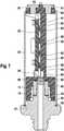
Figur 1 einen Befestigungsflansch mit aufgeschweißter Druckmesszelle, - die
Figur 2 einen Schaltungsträger in der Ansicht von unten, - die
Figur 3 eine bestückte Platine vor dem Kleben auf den Schaltungsträger, - die
Figur 4 die Rückseite der Leiterplatte mit zugehörigem Schaltungsträger in einer anderen Ansicht, - die
Figur 5 den Schaltungsträger mit aufgeklebter Leiterplatte, - die
Figur 6 die Zentrierstege zur Lagefixierung der Leiterplatte auf dem Schaltungsträger, sowie - die
Figur 7 eine Schnittdarstellung durch die Anschlusseinheit mit aufgesetzter Schutzhülse.
- the
FIG. 1 a mounting flange with welded pressure measuring cell, - the
FIG. 2 a circuit carrier in the view from below, - the
FIG. 3 a populated board before sticking to the circuit board, - the
FIG. 4 the back of the circuit board with associated circuit carrier in another view, - the
FIG. 5 the circuit board with glued circuit board, - the
FIG. 6 the Zentrierstege for fixing the position of the circuit board on the circuit board, as well - the
FIG. 7 a sectional view through the connection unit with attached protective sleeve.
Der hydraulische Druck eines magnetventilgesteuerten Fluids in einem Bremssystem wird durch eine Druckmesszelle 14 in ein elektrisches Signal umgesetzt. Hierzu ist die Druckmesszelle 14 auf einem Befestigungsflansch 17 so aufgesetzt, dass abhängig vom Druck des Fluids eine Membran der Druckmesszelle 14 verformt wird. Die Verformung der Membran wird von einer Messbrücke 19 erfasst. Die Druckmesszelle 14 besteht aus einem Träger 15, welcher im Wesentlichen rohrförmig ausgebildet ist. Weiterhin weist der Träger 15 in seinem Mittelabschnitt einen Flansch auf, welcher überwiegend ringförmig ausgeführt ist. Zur positionsgerechten Verbindung mit weiteren Bauteilen weist zumindest ein Abschnitt des Flansches des Trägers 15 eine vorzugsweise rechteckförmige Nase auf. An der im montierten Zustand vom Polkern entfernten Seite der Druckmesszelle 14 sind vier elektrische Kontaktpunkte 18 auf der Messbrücke 19 vorgesehen, über die die Ausgangssignale der Messbrücke 19 abgegriffen werden können. Der Träger 15 der Druckmesszelle 14 ist so ausgeprägt, dass seine Innenseite mit der Oberseite des Polkerns bzw. mit dem Befestigungsflansch 17 formschlüssig zusammenwirkt. Der Träger 15 wird auf den Befestigungsflansch 17 aufgesetzt und durch eine Schweißung, vorzugsweise eine Laserschweißung 16 druckdicht mit diesem verbunden.The hydraulic pressure of a solenoid-controlled fluid in a brake system is converted by a
Auf die Druckmesszelle 14 wird ein Schaltungsträger 20 aufgesetzt. Der Schaltungsträger 20 ist im Wesentlichen zylinderförmig ausgeführt mit einem rechteckförmigen mittleren Abschnitt zur Aufnahme der Leiterplatte 32. Die Innenkontur des unteren Abschnitts des Schaltungsträgers 20 - wie in
Nach oben hin läuft der Schaltungsträger 20 wiederum zylinderförmig aus. Es sind vier Öffnungen 63 vorgesehen, die der Aufnahme von Kontaktmitteln 51, welche nietenförmig ausgeführt sind, dienen. Die Öffnungen 63 werden mit Leitkleberflächen 49 versehen zur Kontaktierung der Kontaktmittel 51 mit den jeweiligen Leiterbahnen 47 mittels Leitkleber. Am oberen zylinderförmigen Bereich des Schaltungsträgers 20 ist in Verlängerung zu dem Mittelsteg 41 ein mittlerer Zentriersteg 38 vorgesehen, welcher mit einer mittleren Zentrierhilfe 36, nämlich eine vorzugsweise u-förmigen Aussparung in der Leiterplatte 32, zusammenwirkt.Towards the top, the
In
In
In
Gemäß
Gemäß
Die in den Figuren gezeichte Anschlusseinheit für eine Druckmesszelle 14 arbeitet wie folgt. Der hydraulische Druck in einem Bremssystem wird durch die beispielsweise auf dem Magnetventil sitzende Druckmesszelle 14 in ein elektrisches Signal umgesetzt. Das elektrische Signal wird durch eine integrierte Schaltung als Beispiel für ein elektronisches Bauteil 26 aufbereitet und verstärkt an ein Steuergerät weitergeleitet. Die Druckmesszelle 14 weist eine Membran auf, die den Druck des Fluids erfasst. Im Inneren des Polkerns des Ventils ist ein mit Fluid gefüllter Kanal ausgebildet, der im Inneren des Befestigungsflansches 17 liegt. Dieser Kanal wird durch die Membran druckdicht verschlossen. Die Druckverhältnisse der Membran werden durch die Messbrücke 19 in entsprechende elektrische Signale umgesetzt. Der Befestigungsflansch 17 wird in dem Hydraulikblock durch Einpressen (Self Clinch) dauerhaft befestigt.The connection unit for a
Der Schaltungsträger 20 wird vorzugsweise in sogenannter MID-2K-Technik ausgebildet. Er ist als spritzgegossener Schaltungsträger 20 aus Kunststoff in MID-Technik (Moulded Interconnected Device) hergestellt, insbesondere im Zweikomponentenspritzguss. Durch MID-Technik lassen sich dreidimensionale Schaltungsstrukturen realisieren. Ein Kunststoff-Vorspritzling aus galvanisierbarem Kunststoff wird mit einem zweiten, nicht galvanisierbaren Kunststoff teilweise überspritzt. Die teilweise hervorstehenden Oberflächen des Vorspritzlings werden durch einen galvanischen Prozess mit einer metallischen Oberfläche beschichtet, so dass dreidimensionale außen liegende Leiterbahnen 47 entstehen. Der Schaltungsträger 20 zeichnet sich durch hohe Gestaltungsfreiheit aus insbesondere durch die Integration elektrischer und mechanischer Funktionen. Dadurch lässt sich die Anschlusseinheit für die Druckmesszelle 14 besonders kompakt aufbauen.The
Über diese dreidimensionalen außen liegenden Leiterbahnen 47 erfolgt nun die Kontaktierung der Kontaktpunkte 18 der Messbrücke 19 mit der Leiterplatte 32. Der elektrische Kontakt zwischen den jeweiligen Leiterbahnen 47 und den Kontaktpunkten 18 stellt ein Leitkleber 55 her, wie in
Die aufgeschweißte Schutzhülle 57 besteht aus Metall und dient zum einen als mechanischer Schutz gegen Verbiegen der Druckmesszelle 14. Andererseits kann sie auch auftretende Überspannungen, beispielsweise ESD-Pulse, zum Befestigungsflansch 17 hin ableiten. Die drei pyramidenförmigen Montagehilfen 61 dienen als Montage-Zentrierhilfe, um die Schutzhülse 57 gut fügen zu können.The welded-on
Die beschriebene Anschlusseinheit für eine Druckmesszelle 14 eignet sich insbesondere für den Einsatz bei Bremsystemen in Kraftfahrzeugen, ist jedoch hierauf nicht eingeschränkt. Insbesondere bei Bremssystemen der Premiumklasse kommen eine Vielzahl von Drucksensoren zum Einsatz bei nur begrenztem Bauraum. Ein bauraumminimierter Drucksensor eignet sich daher gerade für diese Anwendung.The described connection unit for a
Claims (10)
- Connection unit comprising a pressure measuring cell (14), wherein the pressure measuring cell (14) detects, in particular, a pressure of a hydraulic block and has at least one connection point (18) via which at least one electrical output signal of the pressure measuring cell (14) can be tapped off, comprising a printed circuit board (32) and comprising a circuit carrier (20) on which at least the printed circuit board (32) with an electronic component (26) is arranged, wherein the circuit carrier (20), for the purpose of contact to be made with the connection point (18) by the electronic component (26), has at least one three-dimensional, external conductor track (47), wherein at least one contact means (51) is provided, via which contact means an output signal of the electronic component (26) can be tapped off, and wherein the electronic component (26) is connected to the contact means (51) via the at least one three-dimensional, external conductor track (47) of the circuit carrier (20),characterized in that the circuit carrier (20) is of injection-moulded design and is mounted onto the pressure measuring cell (14), wherein the circuit carrier (20) is of substantially cylindrical design with a lower cylindrical region and an upper cylindrical region, which lower cylindrical region and upper cylindrical region are connected to one another via a rectangular middle section, and wherein an inner contour of the lower cylindrical region of the circuit carrier (20), for mechanical connection purposes, is matched to an outer contour of the pressure measuring cell (40) and at least partially surrounds the said pressure measuring cell.
- Connection unit according to Claim 1,characterized in that the circuit carrier (20) has at least one conductive adhesive dome (45) for electrical contact to be made with the conductor track (47) by at least one conductive adhesive surface (53) of the printed circuit board (32).
- Connection unit according to either of the preceding claims,characterized in that at least one opening (63) is provided in the circuit carrier (20) for the purpose of receiving the contact means (51).
- Connection unit according to Claim 3,characterized in that the opening (63) is at least partially surrounded by a conductive adhesive surface (49) for contact to be made with the contact means (51) by the conductor track (47) by means of conductive adhesive (55).
- Connection unit according to one of the preceding claims,characterized in that the circuit carrier (20) has at least one centring web (37, 38) which interacts with the printed circuit board (32) for centring purposes.
- Connection unit according to one of the preceding claims,characterized in that at least one opening (60) is provided in the circuit carrier (20) for the purpose of receiving a sealing means (59), in particular a gel.
- Connection unit according to one of the preceding claims,characterized in that the circuit carrier (20) at least comprises a plastic injection-moulding preform composed of galvanizable plastic and a second, non-galvanizable plastic, wherein the conductor tracks (47) are formed by a galvanic process with metal surface coating being used.
- Connection unit according to one of the preceding claims,characterized in that the circuit carrier (20) has at least one middle web (41) to which a fixing adhesive (43) for fastening the printed circuit board (32) can be applied.
- Connection unit according to one of the preceding claims,characterized in that a protective sleeve (57) is provided, which protective sleeve at least partially surrounds the circuit carrier (20).
- Connection unit according to Claim 9,characterized in that at least one mounting aid (61) is provided for the purpose of guiding the protective sleeve (57).
Applications Claiming Priority (2)
| Application Number | Priority Date | Filing Date | Title |
|---|---|---|---|
| DE102007031980ADE102007031980A1 (en) | 2007-07-10 | 2007-07-10 | Connection unit for a pressure measuring cell |
| PCT/EP2008/058505WO2009007286A2 (en) | 2007-07-10 | 2008-07-02 | Connection unit for a pressure measuring cell |
Publications (2)
| Publication Number | Publication Date |
|---|---|
| EP2167930A2 EP2167930A2 (en) | 2010-03-31 |
| EP2167930B1true EP2167930B1 (en) | 2018-10-03 |
Family
ID=39876648
Family Applications (1)
| Application Number | Title | Priority Date | Filing Date |
|---|---|---|---|
| EP08774639.2AActiveEP2167930B1 (en) | 2007-07-10 | 2008-07-02 | Connection unit for a pressure measuring cell |
Country Status (7)
| Country | Link |
|---|---|
| US (1) | US8104357B2 (en) |
| EP (1) | EP2167930B1 (en) |
| JP (2) | JP5108944B2 (en) |
| KR (1) | KR101519395B1 (en) |
| CN (1) | CN101688814B (en) |
| DE (1) | DE102007031980A1 (en) |
| WO (1) | WO2009007286A2 (en) |
Families Citing this family (49)
| Publication number | Priority date | Publication date | Assignee | Title |
|---|---|---|---|---|
| DE102007031980A1 (en)* | 2007-07-10 | 2009-01-15 | Robert Bosch Gmbh | Connection unit for a pressure measuring cell |
| DE102007041892A1 (en)* | 2007-09-04 | 2009-03-05 | Robert Bosch Gmbh | Electrical switching arrangement with a MID circuit carrier and a connection interface connected thereto |
| EP2224218B1 (en)* | 2009-02-25 | 2018-11-28 | Sensirion Automotive Solutions AG | A sensor in a moulded package and a method for manufacturing the same |
| DE102009045790A1 (en)* | 2009-10-19 | 2011-04-21 | Robert Bosch Gmbh | Pressure sensor, in particular for braking devices |
| DE102010041121A1 (en) | 2010-09-21 | 2012-03-22 | Robert Bosch Gmbh | Circuit carrier and method for producing a circuit carrier |
| DE102010041169A1 (en) | 2010-09-22 | 2012-03-22 | Robert Bosch Gmbh | Pressure sensor, in particular for braking device |
| DE102010043493A1 (en)* | 2010-11-05 | 2012-05-10 | Robert Bosch Gmbh | Electrical component with a contact device |
| DE102011085471B4 (en)* | 2011-10-28 | 2021-09-16 | Robert Bosch Gmbh | Arrangement for direct contacting of contact means and associated connection unit for a pressure measuring cell |
| US20130192379A1 (en)* | 2012-01-27 | 2013-08-01 | Neil S. Petrarca | Small form factor microfused silicon strain gage (msg) pressure sensor packaging |
| DE102012204905B4 (en) | 2012-03-27 | 2024-07-11 | Robert Bosch Gmbh | Circuit carrier for a sensor unit and corresponding sensor unit |
| DE102012204911B4 (en) | 2012-03-27 | 2024-09-19 | Robert Bosch Gmbh | Support unit for a circuit board in a sensor unit and corresponding sensor unit |
| DE102012204904A1 (en)* | 2012-03-27 | 2013-10-02 | Robert Bosch Gmbh | sensor unit |
| JP5728437B2 (en)* | 2012-07-17 | 2015-06-03 | 長野計器株式会社 | Physical quantity measuring device and method of manufacturing physical quantity measuring device |
| DE102012215554B4 (en) | 2012-09-03 | 2021-09-30 | Robert Bosch Gmbh | Conductive adhesive connection between two contact partners and method for producing a conductive adhesive connection |
| HUE031423T2 (en)* | 2013-01-30 | 2017-07-28 | Grieshaber Vega Kg | Adapter device with a mechanical interface for a measuring device housing |
| US9611821B2 (en) | 2013-02-18 | 2017-04-04 | Illinois Tool Works Inc. | Engine manifold sensor assembly |
| US9310266B2 (en)* | 2013-05-08 | 2016-04-12 | Sensata Technologies, Inc. | Strain gauge pressure sensor |
| DE102013212171A1 (en) | 2013-06-26 | 2014-12-31 | Robert Bosch Gmbh | Electrical contacting method and corresponding pressure sensor unit |
| DE102013212254A1 (en)* | 2013-06-26 | 2014-12-31 | Robert Bosch Gmbh | MID component, method of manufacture |
| DE102013212300A1 (en) | 2013-06-26 | 2014-12-31 | Robert Bosch Gmbh | Interface for a printed circuit board and corresponding sensor unit |
| DE102013212305A1 (en) | 2013-06-26 | 2014-12-31 | Robert Bosch Gmbh | Electrical contacting method and corresponding pressure sensor unit |
| DE102013212187A1 (en) | 2013-06-26 | 2014-12-31 | Robert Bosch Gmbh | Arrangement for deriving high-frequency interference and corresponding sensor unit |
| DE102013212591A1 (en) | 2013-06-28 | 2014-12-31 | Robert Bosch Gmbh | Electrical contacting method and corresponding pressure sensor unit |
| DE102013223442A1 (en)* | 2013-11-18 | 2015-05-21 | Robert Bosch Gmbh | Pressure sensor arrangement for detecting a pressure of a fluid medium in a measuring space |
| FR3016038B1 (en)* | 2013-12-31 | 2016-11-04 | Valeo Systemes De Controle Moteur | PRESSURE MEASURING DEVICE |
| DE102014216158A1 (en)* | 2014-02-17 | 2015-08-20 | Robert Bosch Gmbh | Connection device for a pressure sensor, pressure sensor and method for producing a connection device |
| JP6093323B2 (en)* | 2014-03-26 | 2017-03-08 | 長野計器株式会社 | Physical quantity measuring apparatus and manufacturing method thereof |
| JP6170879B2 (en)* | 2014-05-29 | 2017-07-26 | センサータ テクノロジーズ インコーポレーテッド | Strain gauge pressure sensor |
| CN105181216B (en)* | 2014-05-29 | 2020-10-16 | 森萨塔科技公司 | Strain gauge type pressure sensor |
| KR102242428B1 (en)* | 2014-06-03 | 2021-04-19 | 센사타 테크놀로지스, 인크 | Strain gauge pressure sensor |
| FR3024542B1 (en)* | 2014-07-31 | 2016-09-02 | Continental Automotive France | SUPPORT OF AN ELECTRONIC MODULE OF A PRESSURE MEASURING SENSOR |
| KR101945587B1 (en) | 2014-08-19 | 2019-02-07 | 타이코에이엠피 주식회사 | A pressure sensor |
| US10205291B2 (en)* | 2015-02-06 | 2019-02-12 | Masimo Corporation | Pogo pin connector |
| BR112017016302B1 (en) | 2015-02-06 | 2022-12-06 | Masimo Corporation | PHYSIOLOGICAL SENSOR MANUFACTURING METHOD WITH EFFICIENT FLEXIBLE CIRCUIT |
| KR101787703B1 (en)* | 2015-11-02 | 2017-10-19 | 대양전기공업 주식회사 | A sensor |
| KR101787679B1 (en)* | 2015-11-02 | 2017-10-19 | 대양전기공업 주식회사 | A sensor |
| CN107290099B (en) | 2016-04-11 | 2021-06-08 | 森萨塔科技公司 | Pressure sensor, plug for a pressure sensor and method for producing a plug |
| EP3236226B1 (en) | 2016-04-20 | 2019-07-24 | Sensata Technologies, Inc. | Method of manufacturing a pressure sensor |
| DE102016214940A1 (en)* | 2016-08-11 | 2018-02-15 | Robert Bosch Gmbh | Pressure measuring cell and method for applying a measuring structure |
| DE102017205992A1 (en)* | 2017-04-07 | 2018-10-11 | Robert Bosch Gmbh | Sensor carrier for a pressure measuring cell and corresponding pressure sensor unit and corresponding fluid assembly |
| US10545064B2 (en) | 2017-05-04 | 2020-01-28 | Sensata Technologies, Inc. | Integrated pressure and temperature sensor |
| US11153985B2 (en)* | 2017-06-29 | 2021-10-19 | Rosemount Inc. | Modular hybrid circuit packaging |
| US10323998B2 (en) | 2017-06-30 | 2019-06-18 | Sensata Technologies, Inc. | Fluid pressure sensor |
| US10724907B2 (en) | 2017-07-12 | 2020-07-28 | Sensata Technologies, Inc. | Pressure sensor element with glass barrier material configured for increased capacitive response |
| DE102017214599A1 (en)* | 2017-08-22 | 2019-02-28 | Robert Bosch Gmbh | Connecting device for a sensor |
| US10557770B2 (en) | 2017-09-14 | 2020-02-11 | Sensata Technologies, Inc. | Pressure sensor with improved strain gauge |
| DE102017220905A1 (en)* | 2017-11-23 | 2019-05-23 | Robert Bosch Gmbh | Sensor unit for a vehicle |
| ES1217769Y (en)* | 2018-07-26 | 2018-12-13 | Cebi Electromechanical Components Spain S A | PRESSURE METER FOR FLUID CIRCUITS |
| US12200888B2 (en) | 2022-02-01 | 2025-01-14 | Rosemount Inc. | Customization of process variable transmitter with hermetically sealed electronics |
Citations (3)
| Publication number | Priority date | Publication date | Assignee | Title |
|---|---|---|---|---|
| EP0710827A2 (en)* | 1994-11-07 | 1996-05-08 | Matsushita Electric Industrial Co., Ltd. | Combustion pressure sensor and fabrication method thereof |
| JPH08201203A (en)* | 1995-01-31 | 1996-08-09 | Kyowa Electron Instr Co Ltd | Pressure transmitter and method of assembling pressure transmitter |
| JPH08261857A (en)* | 1995-03-27 | 1996-10-11 | Matsushita Electric Ind Co Ltd | Pressure sensor |
Family Cites Families (38)
| Publication number | Priority date | Publication date | Assignee | Title |
|---|---|---|---|---|
| CN1106537A (en)* | 1994-02-07 | 1995-08-09 | 张益敏 | Manometer |
| JP3465996B2 (en)* | 1995-05-26 | 2003-11-10 | 株式会社シチズン電子 | Pressure sensor |
| JPH09222371A (en)* | 1996-02-16 | 1997-08-26 | Fuji Koki:Kk | Pressure sensor |
| JP3211074B2 (en)* | 1996-04-23 | 2001-09-25 | 松下電工株式会社 | Infrared detector |
| JP3209120B2 (en) | 1996-06-12 | 2001-09-17 | 松下電工株式会社 | Pressure sensor |
| JP3209121B2 (en)* | 1996-06-12 | 2001-09-17 | 松下電工株式会社 | Pressure sensor |
| JP3209119B2 (en)* | 1996-07-30 | 2001-09-17 | 松下電工株式会社 | Pressure sensor |
| DE19640261C2 (en)* | 1996-09-30 | 1998-07-16 | Siemens Ag | Valve control unit with three-dimensional circuit board in MID technology |
| JPH1144599A (en)* | 1997-07-29 | 1999-02-16 | Tec Corp | Pressure sensor unit |
| JPH1194665A (en)* | 1997-09-19 | 1999-04-09 | Toshiba Tec Corp | Pressure sensor |
| JP3407631B2 (en)* | 1998-01-27 | 2003-05-19 | 松下電工株式会社 | Pressure sensor |
| JP2000121476A (en) | 1998-10-14 | 2000-04-28 | Toyota Motor Corp | Sensor |
| JP2000199721A (en)* | 1998-10-29 | 2000-07-18 | Matsushita Electric Works Ltd | Infrared detector |
| US6591684B2 (en)* | 1998-12-28 | 2003-07-15 | Kelsey-Hayes Company | Pressure sensor intergrated into an electro-hydraulic control unit |
| JP2001050840A (en)* | 1999-08-04 | 2001-02-23 | Hokuriku Electric Ind Co Ltd | Capacitance-type pressure sensor element |
| JP3800880B2 (en)* | 1999-08-26 | 2006-07-26 | 松下電工株式会社 | Receiver unit |
| DE10014992C2 (en)* | 2000-03-25 | 2002-01-31 | Bosch Gmbh Robert | sensor arrangement |
| DE50110504D1 (en) | 2000-05-11 | 2006-08-31 | Continental Teves Ag & Co Ohg | BRAKING DEVICE WITH INTEGRATED PRESSURE SENSOR MODULE |
| JP3438879B2 (en)* | 2001-02-28 | 2003-08-18 | 日本精機株式会社 | Pressure detector |
| DE20111343U1 (en)* | 2001-07-07 | 2001-10-18 | Abb Patent Gmbh, 68309 Mannheim | Measuring unit for differential pressure measurement |
| DE10134359A1 (en)* | 2001-07-14 | 2003-02-06 | Endress & Hauser Gmbh & Co Kg | Relativdruckmeßgerät |
| JP2003130742A (en)* | 2001-10-29 | 2003-05-08 | Matsushita Electric Works Ltd | Semiconductor pressure sensor |
| DE10244760A1 (en)* | 2002-02-26 | 2003-10-09 | Continental Teves Ag & Co Ohg | Pressure sensor structural component for a motor vehicle brake unit has electric connection for measuring element, contact carrier and threading funnel for inserting a contact pin |
| JP3915605B2 (en)* | 2002-06-12 | 2007-05-16 | 株式会社デンソー | Pressure sensor device |
| JP2004193879A (en)* | 2002-12-10 | 2004-07-08 | Toyo Commun Equip Co Ltd | Surface-mounted saw device |
| DE10354189A1 (en)* | 2003-04-24 | 2004-11-11 | Continental Teves Ag & Co. Ohg | Pressure sensor assembly, especially for a motor vehicle braking system has a pressure element mounting in the form of a pressure pipe with a pressure measurement element and electronics contained within a sealed housing |
| DE102004032984A1 (en)* | 2004-07-08 | 2006-01-26 | Robert Bosch Gmbh | Space-optimized sensor connection |
| DE102004033846A1 (en) | 2004-07-13 | 2006-02-09 | Robert Bosch Gmbh | Valve for control of fluids in brake system of vehicle has actuating unit to operate shut-off element, a resetting element to return shut-off element to original position, and fluid pressure sensor installed integrally in valve |
| JP2006220456A (en)* | 2005-02-08 | 2006-08-24 | Denso Corp | Pressure sensor and its manufacturing method |
| DE202005011253U1 (en)* | 2005-07-14 | 2005-10-13 | Microelectronic Packaging Dresden Gmbh | 3 D pressure sensor has encapsulated sensor chip facing hole and ASIC processing circuit mounted above it under cap |
| DE102005046008B4 (en) | 2005-09-26 | 2007-05-24 | Infineon Technologies Ag | Semiconductor sensor component with sensor chip and method for producing the same |
| DE202005017626U1 (en)* | 2005-11-09 | 2006-01-05 | Aktiv-Sensor Gmbh | Pressure sensor unit with optional intelligence includes pressure injection molded casing with conductive tracks, molded interconnect device support surface and sensor opening |
| EP1966577B1 (en)* | 2005-12-31 | 2012-07-25 | Endress+Hauser GmbH+Co. KG | Pressure-measuring cell |
| JP2008008829A (en)* | 2006-06-30 | 2008-01-17 | Denso Corp | Pressure sensor |
| DE102007016475B4 (en)* | 2007-04-05 | 2017-03-23 | Robert Bosch Gmbh | Connection unit for a pressure sensor |
| DE102007016474A1 (en)* | 2007-04-05 | 2008-10-09 | Robert Bosch Gmbh | Connection unit for a pressure measuring cell |
| DE102007016473A1 (en)* | 2007-04-05 | 2008-10-09 | Robert Bosch Gmbh | Connection unit for a pressure measuring cell |
| DE102007031980A1 (en)* | 2007-07-10 | 2009-01-15 | Robert Bosch Gmbh | Connection unit for a pressure measuring cell |
- 2007
- 2007-07-10DEDE102007031980Apatent/DE102007031980A1/ennot_activeWithdrawn
- 2008
- 2008-07-02KRKR1020107000425Apatent/KR101519395B1/enactiveActive
- 2008-07-02WOPCT/EP2008/058505patent/WO2009007286A2/enactiveApplication Filing
- 2008-07-02JPJP2010515471Apatent/JP5108944B2/enactiveActive
- 2008-07-02EPEP08774639.2Apatent/EP2167930B1/enactiveActive
- 2008-07-02CNCN2008800240402Apatent/CN101688814B/enactiveActive
- 2008-07-02USUS12/596,522patent/US8104357B2/enactiveActive
- 2012
- 2012-08-10JPJP2012178739Apatent/JP5678011B2/enactiveActive
Patent Citations (3)
| Publication number | Priority date | Publication date | Assignee | Title |
|---|---|---|---|---|
| EP0710827A2 (en)* | 1994-11-07 | 1996-05-08 | Matsushita Electric Industrial Co., Ltd. | Combustion pressure sensor and fabrication method thereof |
| JPH08201203A (en)* | 1995-01-31 | 1996-08-09 | Kyowa Electron Instr Co Ltd | Pressure transmitter and method of assembling pressure transmitter |
| JPH08261857A (en)* | 1995-03-27 | 1996-10-11 | Matsushita Electric Ind Co Ltd | Pressure sensor |
Also Published As
| Publication number | Publication date |
|---|---|
| DE102007031980A1 (en) | 2009-01-15 |
| CN101688814A (en) | 2010-03-31 |
| JP2012255800A (en) | 2012-12-27 |
| WO2009007286A3 (en) | 2009-02-26 |
| EP2167930A2 (en) | 2010-03-31 |
| JP2010533284A (en) | 2010-10-21 |
| US20100192696A1 (en) | 2010-08-05 |
| KR101519395B1 (en) | 2015-05-12 |
| WO2009007286A2 (en) | 2009-01-15 |
| US8104357B2 (en) | 2012-01-31 |
| CN101688814B (en) | 2012-02-08 |
| JP5678011B2 (en) | 2015-02-25 |
| KR20100031735A (en) | 2010-03-24 |
| JP5108944B2 (en) | 2012-12-26 |
Similar Documents
| Publication | Publication Date | Title |
|---|---|---|
| EP2167930B1 (en) | Connection unit for a pressure measuring cell | |
| EP1239710B1 (en) | Electronic assembly | |
| DE102012204905B4 (en) | Circuit carrier for a sensor unit and corresponding sensor unit | |
| EP1518099B1 (en) | High-pressure sensor housing comprising a connection element (emi-shield) | |
| DE102012204904A1 (en) | sensor unit | |
| DE102012204911B4 (en) | Support unit for a circuit board in a sensor unit and corresponding sensor unit | |
| DE102010041169A1 (en) | Pressure sensor, in particular for braking device | |
| WO2013143748A1 (en) | Sensor for detecting a pressure and a temperature of a fluid medium | |
| DE102014221368A1 (en) | Connection device for a sensor and associated sensor | |
| EP0829003A1 (en) | Pressure sensor and method of producing the same | |
| DE102014216158A1 (en) | Connection device for a pressure sensor, pressure sensor and method for producing a connection device | |
| DE102013220091A1 (en) | pressure sensor | |
| EP2134578B1 (en) | Connector unit for a pressure measurement cell | |
| EP2137506A1 (en) | Connecting unit for a pressure measuring cell | |
| EP2108934A2 (en) | Capacitive pressure measuring device and its manufacturing method | |
| WO2009121426A2 (en) | Distance encoder sensor and method for producing a distance encoder sensor by means of inserting and connecting with force/form fit | |
| DE102016220750A1 (en) | Pressure sensor and method for producing a pressure sensor | |
| DE102019206840A1 (en) | Sensor arrangement for determining a pressure of a fluid medium | |
| DE102019208015A1 (en) | Sensor arrangement for determining a pressure of a fluid medium | |
| WO2021151535A1 (en) | Pressure sensor unit | |
| DE102012222491A1 (en) | Electronic component with a molded component housing | |
| DE102018207210A1 (en) | Sensor unit for a vehicle | |
| DE102008003954A1 (en) | Printed circuit board carrier and method for producing a conductor carrier | |
| WO2008122467A1 (en) | Connector unit for a pressure measurement cell | |
| DE102019200378A1 (en) | Pressure detection device for a measuring device for measuring a pressure condition value of a plant sample and method for producing a pressure detection device |
Legal Events
| Date | Code | Title | Description |
|---|---|---|---|
| PUAI | Public reference made under article 153(3) epc to a published international application that has entered the european phase | Free format text:ORIGINAL CODE: 0009012 | |
| 17P | Request for examination filed | Effective date:20100210 | |
| AK | Designated contracting states | Kind code of ref document:A2 Designated state(s):AT BE BG CH CY CZ DE DK EE ES FI FR GB GR HR HU IE IS IT LI LT LU LV MC MT NL NO PL PT RO SE SI SK TR | |
| AX | Request for extension of the european patent | Extension state:AL BA MK RS | |
| TPAC | Observations filed by third parties | Free format text:ORIGINAL CODE: EPIDOSNTIPA | |
| DAX | Request for extension of the european patent (deleted) | ||
| STAA | Information on the status of an ep patent application or granted ep patent | Free format text:STATUS: EXAMINATION IS IN PROGRESS | |
| GRAP | Despatch of communication of intention to grant a patent | Free format text:ORIGINAL CODE: EPIDOSNIGR1 | |
| STAA | Information on the status of an ep patent application or granted ep patent | Free format text:STATUS: GRANT OF PATENT IS INTENDED | |
| INTG | Intention to grant announced | Effective date:20180622 | |
| GRAS | Grant fee paid | Free format text:ORIGINAL CODE: EPIDOSNIGR3 | |
| GRAA | (expected) grant | Free format text:ORIGINAL CODE: 0009210 | |
| STAA | Information on the status of an ep patent application or granted ep patent | Free format text:STATUS: THE PATENT HAS BEEN GRANTED | |
| AK | Designated contracting states | Kind code of ref document:B1 Designated state(s):AT BE BG CH CY CZ DE DK EE ES FI FR GB GR HR HU IE IS IT LI LT LU LV MC MT NL NO PL PT RO SE SI SK TR | |
| REG | Reference to a national code | Ref country code:GB Ref legal event code:FG4D Free format text:NOT ENGLISH | |
| REG | Reference to a national code | Ref country code:CH Ref legal event code:EP Ref country code:AT Ref legal event code:REF Ref document number:1049113 Country of ref document:AT Kind code of ref document:T Effective date:20181015 | |
| REG | Reference to a national code | Ref country code:IE Ref legal event code:FG4D Free format text:LANGUAGE OF EP DOCUMENT: GERMAN Ref country code:DE Ref legal event code:R096 Ref document number:502008016375 Country of ref document:DE | |
| REG | Reference to a national code | Ref country code:NL Ref legal event code:MP Effective date:20181003 | |
| REG | Reference to a national code | Ref country code:LT Ref legal event code:MG4D | |
| PG25 | Lapsed in a contracting state [announced via postgrant information from national office to epo] | Ref country code:NL Free format text:LAPSE BECAUSE OF FAILURE TO SUBMIT A TRANSLATION OF THE DESCRIPTION OR TO PAY THE FEE WITHIN THE PRESCRIBED TIME-LIMIT Effective date:20181003 | |
| PG25 | Lapsed in a contracting state [announced via postgrant information from national office to epo] | Ref country code:LV Free format text:LAPSE BECAUSE OF FAILURE TO SUBMIT A TRANSLATION OF THE DESCRIPTION OR TO PAY THE FEE WITHIN THE PRESCRIBED TIME-LIMIT Effective date:20181003 Ref country code:LT Free format text:LAPSE BECAUSE OF FAILURE TO SUBMIT A TRANSLATION OF THE DESCRIPTION OR TO PAY THE FEE WITHIN THE PRESCRIBED TIME-LIMIT Effective date:20181003 Ref country code:ES Free format text:LAPSE BECAUSE OF FAILURE TO SUBMIT A TRANSLATION OF THE DESCRIPTION OR TO PAY THE FEE WITHIN THE PRESCRIBED TIME-LIMIT Effective date:20181003 Ref country code:BG Free format text:LAPSE BECAUSE OF FAILURE TO SUBMIT A TRANSLATION OF THE DESCRIPTION OR TO PAY THE FEE WITHIN THE PRESCRIBED TIME-LIMIT Effective date:20190103 Ref country code:PL Free format text:LAPSE BECAUSE OF FAILURE TO SUBMIT A TRANSLATION OF THE DESCRIPTION OR TO PAY THE FEE WITHIN THE PRESCRIBED TIME-LIMIT Effective date:20181003 Ref country code:HR Free format text:LAPSE BECAUSE OF FAILURE TO SUBMIT A TRANSLATION OF THE DESCRIPTION OR TO PAY THE FEE WITHIN THE PRESCRIBED TIME-LIMIT Effective date:20181003 Ref country code:IS Free format text:LAPSE BECAUSE OF FAILURE TO SUBMIT A TRANSLATION OF THE DESCRIPTION OR TO PAY THE FEE WITHIN THE PRESCRIBED TIME-LIMIT Effective date:20190203 Ref country code:CZ Free format text:LAPSE BECAUSE OF FAILURE TO SUBMIT A TRANSLATION OF THE DESCRIPTION OR TO PAY THE FEE WITHIN THE PRESCRIBED TIME-LIMIT Effective date:20181003 Ref country code:FI Free format text:LAPSE BECAUSE OF FAILURE TO SUBMIT A TRANSLATION OF THE DESCRIPTION OR TO PAY THE FEE WITHIN THE PRESCRIBED TIME-LIMIT Effective date:20181003 Ref country code:NO Free format text:LAPSE BECAUSE OF FAILURE TO SUBMIT A TRANSLATION OF THE DESCRIPTION OR TO PAY THE FEE WITHIN THE PRESCRIBED TIME-LIMIT Effective date:20190103 | |
| PG25 | Lapsed in a contracting state [announced via postgrant information from national office to epo] | Ref country code:GR Free format text:LAPSE BECAUSE OF FAILURE TO SUBMIT A TRANSLATION OF THE DESCRIPTION OR TO PAY THE FEE WITHIN THE PRESCRIBED TIME-LIMIT Effective date:20190104 Ref country code:PT Free format text:LAPSE BECAUSE OF FAILURE TO SUBMIT A TRANSLATION OF THE DESCRIPTION OR TO PAY THE FEE WITHIN THE PRESCRIBED TIME-LIMIT Effective date:20190203 Ref country code:SE Free format text:LAPSE BECAUSE OF FAILURE TO SUBMIT A TRANSLATION OF THE DESCRIPTION OR TO PAY THE FEE WITHIN THE PRESCRIBED TIME-LIMIT Effective date:20181003 | |
| REG | Reference to a national code | Ref country code:DE Ref legal event code:R097 Ref document number:502008016375 Country of ref document:DE | |
| PG25 | Lapsed in a contracting state [announced via postgrant information from national office to epo] | Ref country code:DK Free format text:LAPSE BECAUSE OF FAILURE TO SUBMIT A TRANSLATION OF THE DESCRIPTION OR TO PAY THE FEE WITHIN THE PRESCRIBED TIME-LIMIT Effective date:20181003 | |
| PLBE | No opposition filed within time limit | Free format text:ORIGINAL CODE: 0009261 | |
| STAA | Information on the status of an ep patent application or granted ep patent | Free format text:STATUS: NO OPPOSITION FILED WITHIN TIME LIMIT | |
| PG25 | Lapsed in a contracting state [announced via postgrant information from national office to epo] | Ref country code:SK Free format text:LAPSE BECAUSE OF FAILURE TO SUBMIT A TRANSLATION OF THE DESCRIPTION OR TO PAY THE FEE WITHIN THE PRESCRIBED TIME-LIMIT Effective date:20181003 Ref country code:EE Free format text:LAPSE BECAUSE OF FAILURE TO SUBMIT A TRANSLATION OF THE DESCRIPTION OR TO PAY THE FEE WITHIN THE PRESCRIBED TIME-LIMIT Effective date:20181003 Ref country code:RO Free format text:LAPSE BECAUSE OF FAILURE TO SUBMIT A TRANSLATION OF THE DESCRIPTION OR TO PAY THE FEE WITHIN THE PRESCRIBED TIME-LIMIT Effective date:20181003 | |
| 26N | No opposition filed | Effective date:20190704 | |
| PG25 | Lapsed in a contracting state [announced via postgrant information from national office to epo] | Ref country code:SI Free format text:LAPSE BECAUSE OF FAILURE TO SUBMIT A TRANSLATION OF THE DESCRIPTION OR TO PAY THE FEE WITHIN THE PRESCRIBED TIME-LIMIT Effective date:20181003 | |
| PG25 | Lapsed in a contracting state [announced via postgrant information from national office to epo] | Ref country code:MC Free format text:LAPSE BECAUSE OF FAILURE TO SUBMIT A TRANSLATION OF THE DESCRIPTION OR TO PAY THE FEE WITHIN THE PRESCRIBED TIME-LIMIT Effective date:20181003 | |
| REG | Reference to a national code | Ref country code:CH Ref legal event code:PL | |
| PG25 | Lapsed in a contracting state [announced via postgrant information from national office to epo] | Ref country code:TR Free format text:LAPSE BECAUSE OF FAILURE TO SUBMIT A TRANSLATION OF THE DESCRIPTION OR TO PAY THE FEE WITHIN THE PRESCRIBED TIME-LIMIT Effective date:20181003 | |
| REG | Reference to a national code | Ref country code:BE Ref legal event code:MM Effective date:20190731 | |
| PG25 | Lapsed in a contracting state [announced via postgrant information from national office to epo] | Ref country code:CH Free format text:LAPSE BECAUSE OF NON-PAYMENT OF DUE FEES Effective date:20190731 Ref country code:BE Free format text:LAPSE BECAUSE OF NON-PAYMENT OF DUE FEES Effective date:20190731 Ref country code:LU Free format text:LAPSE BECAUSE OF NON-PAYMENT OF DUE FEES Effective date:20190702 Ref country code:LI Free format text:LAPSE BECAUSE OF NON-PAYMENT OF DUE FEES Effective date:20190731 | |
| PG25 | Lapsed in a contracting state [announced via postgrant information from national office to epo] | Ref country code:IE Free format text:LAPSE BECAUSE OF NON-PAYMENT OF DUE FEES Effective date:20190702 | |
| REG | Reference to a national code | Ref country code:AT Ref legal event code:MM01 Ref document number:1049113 Country of ref document:AT Kind code of ref document:T Effective date:20190702 | |
| PG25 | Lapsed in a contracting state [announced via postgrant information from national office to epo] | Ref country code:AT Free format text:LAPSE BECAUSE OF NON-PAYMENT OF DUE FEES Effective date:20190702 | |
| PG25 | Lapsed in a contracting state [announced via postgrant information from national office to epo] | Ref country code:CY Free format text:LAPSE BECAUSE OF FAILURE TO SUBMIT A TRANSLATION OF THE DESCRIPTION OR TO PAY THE FEE WITHIN THE PRESCRIBED TIME-LIMIT Effective date:20181003 | |
| PG25 | Lapsed in a contracting state [announced via postgrant information from national office to epo] | Ref country code:HU Free format text:LAPSE BECAUSE OF FAILURE TO SUBMIT A TRANSLATION OF THE DESCRIPTION OR TO PAY THE FEE WITHIN THE PRESCRIBED TIME-LIMIT; INVALID AB INITIO Effective date:20080702 Ref country code:MT Free format text:LAPSE BECAUSE OF FAILURE TO SUBMIT A TRANSLATION OF THE DESCRIPTION OR TO PAY THE FEE WITHIN THE PRESCRIBED TIME-LIMIT Effective date:20181003 | |
| PGFP | Annual fee paid to national office [announced via postgrant information from national office to epo] | Ref country code:DE Payment date:20240919 Year of fee payment:17 | |
| PGFP | Annual fee paid to national office [announced via postgrant information from national office to epo] | Ref country code:GB Payment date:20240723 Year of fee payment:17 | |
| PGFP | Annual fee paid to national office [announced via postgrant information from national office to epo] | Ref country code:FR Payment date:20240724 Year of fee payment:17 | |
| PGFP | Annual fee paid to national office [announced via postgrant information from national office to epo] | Ref country code:IT Payment date:20240731 Year of fee payment:17 |