EP2167251B1 - Device for handling a load such as a sheet metal coil - Google Patents
Device for handling a load such as a sheet metal coilDownload PDFInfo
- Publication number
- EP2167251B1 EP2167251B1EP08805615.5AEP08805615AEP2167251B1EP 2167251 B1EP2167251 B1EP 2167251B1EP 08805615 AEP08805615 AEP 08805615AEP 2167251 B1EP2167251 B1EP 2167251B1
- Authority
- EP
- European Patent Office
- Prior art keywords
- load
- holder
- frame
- reel
- axis position
- Prior art date
- Legal status (The legal status is an assumption and is not a legal conclusion. Google has not performed a legal analysis and makes no representation as to the accuracy of the status listed.)
- Active
Links
Images


Classifications
- B—PERFORMING OPERATIONS; TRANSPORTING
- B21—MECHANICAL METAL-WORKING WITHOUT ESSENTIALLY REMOVING MATERIAL; PUNCHING METAL
- B21C—MANUFACTURE OF METAL SHEETS, WIRE, RODS, TUBES, PROFILES OR LIKE SEMI-MANUFACTURED PRODUCTS OTHERWISE THAN BY ROLLING; AUXILIARY OPERATIONS USED IN CONNECTION WITH METAL-WORKING WITHOUT ESSENTIALLY REMOVING MATERIAL
- B21C47/00—Winding-up, coiling or winding-off metal wire, metal band or other flexible metal material characterised by features relevant to metal processing only
- B21C47/24—Transferring coils to or from winding apparatus or to or from operative position therein; Preventing uncoiling during transfer
- B21C47/242—Devices for swinging the coil from horizontal to vertical, or vice versa
Definitions
- the present inventionrelates to a device for handling a load, such as a sheet metal coil according to the preamble of claim 1, comprising a support capable of carrying said load, said support being able to rotate on a chassis between at least one first position in which the axis of said load is vertical, so-called vertical axis position, and a second position in which the axis of said load is horizontal, so-called horizontal axis position, the frame being coupled to drive means to be mobile so as to be able to load and / or unload said load on another machine, such as a reel, and the support comprising means for holding and positioning said load arranged to hold said load during its change of position and depositing and / or resuming said load on or of said machine.
- a device for handling a loadsuch as a sheet metal coil according to the preamble of claim 1
- a supportcapable of carrying said load, said support being able to rotate on a chassis between at least one first position in which the axis of said load is vertical, so-called vertical
- strips, sheets and the like which are packaged in coilsare used to feed the production lines of metal parts obtained by cutting, stamping, forming, etc.
- These production linesare fed by feeders arranged at the head of line, on which the coils are carried by horizontal axis mandrels, in most cases.
- the coilsare stacked, separated by planks, and rimmed on pallets or the like, to be stored and transported, the axis of these coils being vertical. It is therefore necessary to raise, swing or rotate a quarter turn each coil before being able to load on a reel, so as to move its axis from the vertical position to the horizontal position.
- the publication US 4,322,198proposes an automatic solution using an angled arm controlled in rotation to change the position of the axis of the sheet metal coil carried by the arm.
- the publication US 3,395,813proposes another automatic solution using the weight of the spool for tilting a support from a position with a vertical axis to a position with a horizontal axis, maintaining the support in position with a vertical axis and returning the support in position with a vertical axis and it is held in this position by an actuator.
- This additional operationconsists in taking the coil in the horizontal axis position, positioning it and engaging it on the mandrel of the reel, at a depth exceeding the middle point of the jaws of the mandrel, before removing it.
- the present inventionaims to provide a solution to the problem by means of a simple, economical, compact, reliable and secure handling device, versatile, for switching each coil individually, and combining the tilting operation with the operations of loading and unloading of any type of reel.
- the inventionrelates to a handling device of the kind indicated in the preamble, characterized in that said support comprises a central opening to be traversed by a mandrel of a reel during the loading and unloading operations of said load and in that said means for holding and positioning the load on the support are movable in translation radial and / or axial to align the axis of the load with the axis of the mandrel of the reel during said operations.
- these holding and positioning meansmay comprise a hook adapted to bear on the inner bore of the load or a cradle able to bear on the outside of the load.
- the axis of rotation of the support on the chassiscan be offset relative to the center of gravity of the support added with the load, this support being arranged to tilt under the effect of gravity in a direction of rotation. to move from position to vertical axis to position to horizontal axis. In this case, the tilting of the load in at least one direction of rotation is obtained without input of energy.
- the axis of rotation of the support on the framemay be substantially coincidental with the center of gravity of said support plus the load.
- the deviceadvantageously comprises additional drive means coupled to said support to switch from the vertical axis position to the horizontal axis position and vice versa.
- the framemay be movable in translation in guide rails and the drive means may comprise at least one actuator coupled to said frame by a transmission.
- These drive meansare advantageously coupled to the support to switch in the direction of rotation to move from its horizontal axis position to the vertical axis position and may comprise a stand extending between a fixed stop fixed to the guide rails and an integral articulation of the support opposite the axis of rotation.
- the actuating meansmay comprise a fixed cam ramp on which circulates a roller secured to the support opposite the axis of rotation.
- the guide railsare advantageously arranged in the extension of a reel and the actuating means are, in this case, arranged to move the frame of an additional stroke to load and / or unload the reel when the support is in position with horizontal axis.
- the framehas a stop defining the horizontal axis position of the support.
- the cam rampmay comprise a first inclined section corresponding to the travel of the chassis during the rotation of the support and a second horizontal section corresponding to the additional travel of loading and / or unloading of the reel.
- the chassismay be on board a rolling machine constituting said drive means, and may comprise lifting means arranged to position said chassis in height.
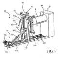
- the figures 1 and 2illustrate a first embodiment of a handling device 30, according to the invention, arranged to switch a load C by a quarter of a turn and to perform in addition the loading and / or unloading of this load C on another machine, such as a reel D provided with a mandrel M adapted to receive the load C.
- This load Cmay be a sheet metal coil, as shown in the figures, deposited by a forklift truck or the like, and intended to feed a reel located at the head of a production line, or an unfinished sheet metal reel to take back from the reel.
- This charge Cmay also consist of a stack of metal coils, as shown schematically in FIG. 3D figure , intended to feed a reel, the reels being deposited one after the other.
- the handling device 30comprises a frame 31 movable in translation in guide rails 313 fixed to the ground in the axis of a reel D, this frame being coupled to drive means 35. It comprises a base 310 provided with rolling means housed in the guide rails 313, surmounted by a bracket 311 carrying at its free end a bearing 312 defining the axis of rotation A.
- the frame 31carries a support 32 adapted to receive a load C such that a coil of sheet metal or the like.
- This support 32comprises a frame or the like, rotatable about the axis of rotation A between at least one position with a vertical axis V and a position with a horizontal axis H, and vice versa.
- the axis of rotation Ais in this example offset.
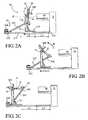
- the drive means 35comprise an actuator 350 such as a geared motor or the like coupled to the frame 31 by a transmission such as a pinion and chain system 351, the chain circulating in a closed loop in the U-shaped guide rails 313. Any other known transmission may also be suitable. They also comprise a stand 352 which extends between a fixed abutment 353 integral with the guide rails 313 and a hinge 354 secured to the support 32 opposite the axis of rotation A. This stand 352 provides a locking function of the position of the support 32 and a rotational drive function of the support 32 in the counterclockwise direction R 'to move it from its horizontal axis position H to its vertical axis position V, as illustrated in FIGS. FIGS. 2A to 2C .
- an actuator 350such as a geared motor or the like coupled to the frame 31 by a transmission such as a pinion and chain system 351, the chain circulating in a closed loop in the U-shaped guide rails 313. Any other known transmission may also be suitable.
- Theyalso
- FIGS. 2A to 2CThe operation of the handling device 30 is explained with reference to FIGS. 2A to 2C in which the device is shown empty.
- the handling device 30In the position illustrated in Figure 2C the handling device 30 is waiting to receive a load C, is remote from the reel D and the support 32 is in its position with a vertical axis V.
- the support 32When a load C is deposited on the support 32, the latter remains locked in its position with vertical axis V thanks to the stand 352 bearing against the fixed stop 353.
- the startup of the actuator 350generates the movement of the frame 31 to the reel D and allows the rotation of the support 32 under the effect of gravity G.
- the articulation 354 of the stand 352travels in a clockwise circle R centered on the fixed stop 353, until the support 32 reaches its position with a horizontal axis H illustrated in FIG.
- FIG 7Adelimited by a stop 314 provided on the frame 31, wherein the load C is facing the reel D.
- This first part of the race of the frame 31is called L1 approach stroke. From this position, the frame 31 continues to move towards the reel D, driving with him the stand 352 whose foot runs in the guide rails 313, to an end stop 355 which stops the actuator 350 and defines the position of loading and / or unloading of the reel D.
- This second part of the Chassis race 31is called L2 load race.
- the load Ccan be transferred from the support 32 to the mandrel M as explained below.
- the return of the handling device 30 to its initial position illustrated in FIG. Figure 2Cis performed by reversing the direction of rotation of the actuator 350 to drive the frame 31 in the opposite direction to the reel D.
- the frame 31retreats a stroke L2 causing the stand 352 to its fixed stop 353 (cf. Fig. 2A ).
- the frame 31continues its displacement opposite the reel D and the stand 352 generates the rotation of the support 32 about its axis of rotation A in the anticlockwise direction R '(cf. Fig. 2B ) to move from its position with horizontal axis H to its position with vertical axis V (cf. Fig. 2C ).
- the handling device 30comprises means for holding and positioning 36 of the load C on the support 32 to prevent any risk of the load C falling and to ensure alignment with the mandrel M of the reel D to be loaded.
- the support 32is preferably perforated to allow the passage of the mandrel M through said support 32.
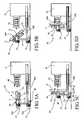
- the support 32consists of a frame defining a central opening 33 sufficient to receive the mandrel M in the example of the figure 3A
- the holding and positioning means 36are in the form of a hook 360 adapted to bear on the internal bore of the load C.
- This hook 360is slidably mounted on the support 32 and its radial position is adjustable to the means of threaded rods 361 for aligning the axis of the load C with the axis of the mandrel M of the reel D. This adjustment is therefore made at the time of putting into operation of the handling device 30.
- the reel Dis equipped with an automatic expansion mandrel M and the jaws of the mandrel M are arranged so as to provide a passage P (cf. Fig. 1 ) for the hook 360 when loading and unloading the reel D.
- the hook 360must be movable in radial translation on the support 32 by means for example of the cylinders 362, as shown in FIG. figure 3B . This radial translation makes it possible to vertically deposit the load C on the jaws of the mandrel M.
- the positioning means 36are designed to bear on the outside of the load C by means for example of a cradle formed by support bars 363, a support V, or the like. In this case, these positioning means 36 are also movable in radial translation on the support 32 by means for example of cylinders 364 to adapt to the outer diameter of the load C.
- the handling device 30,can also be arranged to switch a load C consisting of a stack of several coils of sheets C1, C2, C3, Cn, as packaged, as shown in FIG. 3D figure .
- the positioning means 36are radially movable on the support 32 by cylinders 364 and carry the load C by its outer diameter by means of axially movable support arms 365.
- the support arms 365are axially movable to allow the removal of a single coil C1 at a time on the mandrel M of the reel D.
- the positioning means 36can also carry the load C by its internal bore as in examples of Figures 3A and 3B , and in this case, the hook 360 is also axially movable.
- the cam ramp 356comprises a first inclined section corresponding to the stroke L1 at during which the frame 31 moves in translation towards the reel D and the support 32 switches from its vertical axis position V to its position with a horizontal axis H (cf. Fig. 4A and 4B ), followed by a second horizontal section corresponding to the stroke L2 during which the frame 32 continues to move in translation to bring the load C to the mandrel M of the reel D (cf. Fig. 4C and 4D ).
- the figure 4Dillustrates the manner in which the handling device 30 of the invention makes it possible to load the reel D without the use of other handling equipment thanks to the support 32 which allows the mandrel M to pass through its central opening 33 in order to be able to deposit the load therein. C when the mandrel M extends.
- FIGS. 5A to 5Dillustrate another alternative embodiment of the handling device 30 of the invention wherein the axis of rotation A of the support 32 is substantially coincidental with the center of gravity G of said support 32 plus the load C and in which the tilting of the support 32 between its positions with vertical axis V and horizontal axis H and vice versa is effected by additional drive means 37.
- Theycomprise an actuator 370 such as a motor, a geared motor, a jack, coupled in direct drive or by via a pinion / rack mechanical transmission or the like, to a drive shaft coincident with the axis of rotation A.
- the vertical axis V and horizontal axis positions Hare delimited either by programming the control the actuator 370, or by limit switches provided on the frame 31 and not shown.
- the chassis 31is mounted on rolling means 38 and coupled to the reel D by rails or telescopic guides 380 arranged to delimit the races L1 and L2 of the handling device 30 necessary for the loading and unloading of the reel. D.
- the displacement of the frame 31is controlled by the actuator 350 and any type of mechanical transmission coupled to the rails or telescopic guides 380.
- the support 32has a central opening 33 for the passage of the mandrel M during loading of the reel D and the holding and positioning means 36 of the load C for example in the form of a hook 360 adjustable in radial position.
- FIGS. 6A to 6Dillustrate a second embodiment of a handling device 40 according to the invention in which the frame 31 is mounted on a wheeled vehicle 41 operated by an operator, this rolling machine 41 constituting drive means of said frame 31 and having advantage of not being dedicated to a reel D in particular, but can feed different reels D with the same device.
- the frame 31is similar to that of the previous example and also comprises additional drive means 37 for tilting the support 32 from a vertical axis position V to a horizontal axis position H and vice versa.
- the support 32is also in accordance with the preceding examples in that it comprises a central opening 33 for the passage of the mandrel M and means for holding and positioning 36 of the load C.
- the rolling machine 41comprises vertical guide columns 410 or similar, in or on which slides the frame 31 and lifting means 411, for example in the form of jacks, to move the frame 31 vertically and position the support 32 relative to the axis of the mandrel M of a given reel D.
- This constructionmakes it possible to have a handling device 40 that is versatile and adaptable to different types of reels D.
- indexing stations 50near the reels D (cf. Fig. 7A and 7B ) arranged to receive at least two coils C waiting, arranged side by side in a vertical axis position, and intended to be taken by the handling device 40: for example a full reel waiting to load on the reel D and a reel unfinished from the reel D.
- This indexing station 50comprises a receiving plate 51 worn by feet 52.
- the receiving plate 51has at the right of each coil C a central opening 53 allowing the passage of the support 32 of the handling device 40 under the coil C.
- the feet 52delimit to the right of each coil C an indexing housing 54 adapted to receive the feet of the rolling machine 41 to be able to load a reel pending.
- the lifting means 411 of the handling device 40can lower the support 32 under the coil C to be taken.
- the exemplary embodiments of figures 5 and 6may comprise a support 32 similar to that of the exemplary embodiments of Figures 1 to 4 whose center of gravity G is offset relative to the axis of rotation A to overcome the additional drive means 37.
Landscapes
- Engineering & Computer Science (AREA)
- Mechanical Engineering (AREA)
- Replacement Of Web Rolls (AREA)
- Load-Engaging Elements For Cranes (AREA)
Description
Translated fromFrenchLa présente invention concerne un dispositif de manutention d'une charge, telle qu'une bobine de tôle selon le préambule de la revendication 1, comportant un support apte à porter ladite charge, ce support étant mobile en rotation sur un châssis entre au moins une première position dans laquelle l'axe de ladite charge est vertical, position dite à axe vertical, et une seconde position dans laquelle l'axe de ladite charge est horizontal, position dite à axe horizontal, le châssis étant couplé à des moyens d'entraînement pour être mobile de manière à pouvoir charger et/ou décharger ladite charge sur une autre machine, telle qu'un dévidoir, et le support comportant des moyens de maintien et de positionnement de ladite charge agencés pour tenir ladite charge pendant son changement de position et déposer et/ou reprendre ladite charge sur ou de ladite machine. Un exemple d'un tel dispositif est connu du document
Dans le domaine de la métallurgie, les feuillards, les tôles et similaires qui sont conditionnés en bobines, appelées des « coils », servent à alimenter les lignes de fabrication de pièces métalliques obtenues par découpage, emboutissage, formage, etc. Ces lignes de fabrication sont alimentées par des dévidoirs disposés en tête de ligne, sur lesquels les bobines sont portées par des mandrins à axe horizontal, dans la plupart des cas. Pour des largeurs de bobines inférieures à environ 500 mm, les bobines sont empilées, séparées par des madriers, et cerclées sur des palettes ou similaires, pour être stockées et transportées, l'axe de ces bobines étant vertical. Il est donc nécessaire de relever, basculer ou pivoter d'un quart de tour chaque bobine avant de pouvoir la charger sur un dévidoir, de manière à faire passer son axe de la position verticale à la position horizontale.In the field of metallurgy, strips, sheets and the like which are packaged in coils, called "coils", are used to feed the production lines of metal parts obtained by cutting, stamping, forming, etc. These production lines are fed by feeders arranged at the head of line, on which the coils are carried by horizontal axis mandrels, in most cases. For coil widths less than about 500 mm, the coils are stacked, separated by planks, and rimmed on pallets or the like, to be stored and transported, the axis of these coils being vertical. It is therefore necessary to raise, swing or rotate a quarter turn each coil before being able to load on a reel, so as to move its axis from the vertical position to the horizontal position.
Cette opération est relativement dangereuse. A ce jour, elle est effectuée de différentes manières :
- ▪ par suspension de chaque bobine à un crochet à l'extrémité d'une élingue portée par un pont roulant,
- ▪ par retournement de chaque bobine avec la fourche d'un chariot élévateur (opération très dangereuse),
- ▪ par basculement de l'ensemble de la palette et de la pile de bobines sur une machine appelée « basculeur » du type à virole ou à équerre tournante, qui est une machine très coûteuse et très encombrante. L'inconvénient majeur de cette solution est qu'il faut retourner toute la pile de bobines alors que le besoin en production peut n'être que d'une seule bobine ou même que d'une fraction de cette seule bobine.
- ▪ by suspending each coil at a hook at the end of a sling carried by a traveling crane,
- ▪ by turning each spool with the fork of a forklift (very dangerous operation),
- ▪ by tilting the entire pallet and the coil stack on a machine called "tipper" type ferrule or rotating angle, which is a very expensive and very cumbersome machine. The major disadvantage of this solution is that it is necessary to return the entire coil stack while the production need may be only one coil or even a fraction of this single coil.
La publication
Quelque soit le moyen mis en oeuvre pour réaliser le basculement d'une bobine, les équipements ou machines utilisés ne servent que pour cette opération. Une fois le basculement réalisé, il est nécessaire de charger le dévidoir. Cette opération complémentaire consiste à prélever la bobine en position à axe horizontal, à la positionner et à l'engager sur le mandrin du dévidoir, en profondeur en dépassant le point milieu des mors du mandrin, avant de la déposer.Whatever the means used to perform the tilting of a coil, the equipment or machines used are only used for this operation. Once the tilting is completed, it is necessary to load the reel. This additional operation consists in taking the coil in the horizontal axis position, positioning it and engaging it on the mandrel of the reel, at a depth exceeding the middle point of the jaws of the mandrel, before removing it.
Ce problème existe dans d'autres domaines techniques, tels que l'industrie du papier, l'industrie de la plasturgie, etc. dans lesquels les matériaux sont conditionnés en bobines ou similaire, qui sont des produits lourds à manutentionner.This problem exists in other technical fields, such as the paper industry, the plastics industry, and so on. wherein the materials are packaged in coils or the like, which are heavy products to be handled.
Certaines solutions ont été développées pour répondre en partie à cette fonction complémentaire. Les publications
Les solutions actuelles sont donc incomplètes et non satisfaisantes, notamment pour la sécurité de l'opérateur.Current solutions are therefore incomplete and unsatisfactory, especially for the safety of the operator.
La présente invention vise à apporter une solution au problème posé au moyen d'un dispositif de manutention simple, économique, peu encombrant, fiable et sécurisé, polyvalent, permettant de basculer chaque bobine individuellement, et en combinant l'opération de basculement aux opérations de chargement et de déchargement de tout type de dévidoir.The present invention aims to provide a solution to the problem by means of a simple, economical, compact, reliable and secure handling device, versatile, for switching each coil individually, and combining the tilting operation with the operations of loading and unloading of any type of reel.
Dans ce but, l'invention concerne un dispositif de manutention du genre indiqué en préambule, caractérisé en ce que ledit support comporte une ouverture centrale destinée à être traversée par un mandrin d'un dévidoir lors des opérations de chargement et de déchargement de ladite charge et en ce que lesdits moyens de maintien et de positionnement de la charge sur le support sont mobiles en translation radiale et/ou axiale pour aligner l'axe de la charge avec l'axe du mandrin du dévidoir lors desdites opérations.For this purpose, the invention relates to a handling device of the kind indicated in the preamble, characterized in that said support comprises a central opening to be traversed by a mandrel of a reel during the loading and unloading operations of said load and in that said means for holding and positioning the load on the support are movable in translation radial and / or axial to align the axis of the load with the axis of the mandrel of the reel during said operations.
Ces moyens de maintien et de positionnement peuvent comporter un crochet apte à prendre appui sur l'alésage intérieur de la charge ou un berceau apte à prendre appui sur l'extérieur de la charge. Selon les variantes de réalisation, l'axe de rotation du support sur le châssis peut être décalé par rapport au centre de gravité du support additionné de la charge, ce support étant agencé pour basculer sous l'effet de la gravité dans un sens de rotation pour passer de la position à axe vertical à la position à axe horizontal. Dans ce cas, le basculement de la charge dans au moins un sens de rotation est obtenu sans apport d'énergie.These holding and positioning means may comprise a hook adapted to bear on the inner bore of the load or a cradle able to bear on the outside of the load. According to the variant embodiments, the axis of rotation of the support on the chassis can be offset relative to the center of gravity of the support added with the load, this support being arranged to tilt under the effect of gravity in a direction of rotation. to move from position to vertical axis to position to horizontal axis. In this case, the tilting of the load in at least one direction of rotation is obtained without input of energy.
Selon d'autres variantes de réalisation, l'axe de rotation du support sur le châssis peut être sensiblement confondu avec le centre de gravité dudit support additionné de la charge. Dans ce cas, le dispositif comporte avantageusement des moyens d'entraînement additionnels couplés audit support pour le basculer de la position à axe vertical à la position à axe horizontal et inversement.According to other embodiments, the axis of rotation of the support on the frame may be substantially coincidental with the center of gravity of said support plus the load. In this case, the device advantageously comprises additional drive means coupled to said support to switch from the vertical axis position to the horizontal axis position and vice versa.
Dans une variante de réalisation, le châssis peut être mobile en translation dans des rails de guidage et les moyens d'entraînement peuvent comporter au moins un actionneur couplé audit châssis par une transmission.In an alternative embodiment, the frame may be movable in translation in guide rails and the drive means may comprise at least one actuator coupled to said frame by a transmission.
Ces moyens d'entraînement sont avantageusement couplés au support pour le basculer dans le sens de rotation inverse pour passer de sa position à axe horizontal à la position à axe vertical et peuvent comporter une béquille s'étendant entre une butée fixe solidaire des rails de guidage et une articulation solidaire du support à l'opposé de l'axe de rotation.These drive means are advantageously coupled to the support to switch in the direction of rotation to move from its horizontal axis position to the vertical axis position and may comprise a stand extending between a fixed stop fixed to the guide rails and an integral articulation of the support opposite the axis of rotation.
Dans un autre mode de réalisation, les moyens d'actionnement peuvent comporter une rampe de came fixe sur laquelle circule un galet solidaire du support à l'opposé de l'axe de rotation.In another embodiment, the actuating means may comprise a fixed cam ramp on which circulates a roller secured to the support opposite the axis of rotation.
Les rails de guidage sont avantageusement disposés dans le prolongement d'un dévidoir et les moyens d'actionnement sont, dans ce cas, agencés pour déplacer le châssis d'une course supplémentaire pour charger et/ou décharger le dévidoir lorsque le support est en position à axe horizontal.The guide rails are advantageously arranged in the extension of a reel and the actuating means are, in this case, arranged to move the frame of an additional stroke to load and / or unload the reel when the support is in position with horizontal axis.
De manière préférentielle, le châssis comporte une butée définissant la position à axe horizontal du support.Preferably, the frame has a stop defining the horizontal axis position of the support.
La rampe de came peut comporter un premier tronçon incliné correspondant à la course du châssis pendant la rotation du support et un second tronçon horizontal correspondant à la course supplémentaire de chargement et/ou déchargement du dévidoir.The cam ramp may comprise a first inclined section corresponding to the travel of the chassis during the rotation of the support and a second horizontal section corresponding to the additional travel of loading and / or unloading of the reel.
Dans une autre variante de réalisation, le châssis peut être embarqué sur un engin roulant constituant lesdits moyens d'entraînement, et peut comporter des moyens de levage agencés pour positionner en hauteur ledit châssis.In another variant embodiment, the chassis may be on board a rolling machine constituting said drive means, and may comprise lifting means arranged to position said chassis in height.
La présente invention et ses avantages apparaîtront mieux dans la description suivante de plusieurs modes de réalisation donnés à titre d'exemples non limitatifs, en référence aux dessins annexés, dans lesquels :
- la
figure 1 est une vue en perspective d'un premier mode de réalisation d'un dispositif de manutention selon l'invention, - les
figures 2A à 2C sont des vues de côté du dispositif de lafigure 1 respectivement en position à axe horizontal, en position intermédiaire et en position à axe vertical, - les
figures 3A-D sont des vues de détail de quatre variantes de réalisation des moyens de positionnement prévus sur le dispositif de lafigure 1 , - les
figures 4A à 4D sont des schémas de principe d'une variante de réalisation du dispositif de lafigure 1 montrant les quatre séquences de fonctionnement pour charger une bobine sur un dévidoir, - les
figures 5A à 5D sont des vues schématiques d'une autre variante de réalisation du dispositif de lafigure 1 montrant les mêmes séquences de fonctionnement qu'auxfigures 4A à 4D , - les
figures 6A à 6D sont des vues schématiques d'une seconde forme de réalisation du dispositif de lafigure 1 montrant les même séquences de fonctionnement, et - les
figures 7A et 7B sont des vues en perspective d'une station d'indexage de deux bobines respectivement en attente et en cours de chargement.
- the
figure 1 is a perspective view of a first embodiment of a handling device according to the invention, - the
FIGS. 2A to 2C are side views of the device of thefigure 1 respectively in the horizontal axis position, the intermediate position position and the vertical axis position position, - the
Figures 3A-D are detailed views of four alternative embodiments of the positioning means provided on the device of thefigure 1 , - the
Figures 4A to 4D are schematic diagrams of an alternative embodiment of the device of thefigure 1 showing the four operating sequences to load a coil on a reel, - the
Figures 5A to 5D are schematic views of another alternative embodiment of the device of thefigure 1 showing the same operating sequences asFigures 4A to 4D , - the
Figures 6A to 6D are schematic views of a second embodiment of the device of thefigure 1 showing the same operating sequences, and - the
Figures 7A and 7B are perspective views of an indexing station of two coils respectively waiting and being loaded.
Les
Le dispositif de manutention 30 comporte un châssis 31 mobile en translation dans des rails de guidage 313 fixés au sol dans l'axe d'un dévidoir D, ce châssis étant couplé à des moyens d'entraînement 35. Il comporte un socle 310 pourvu de moyens de roulement logés dans les rails de guidage 313, surmonté d'une potence 311 portant à son extrémité libre un palier 312 définissant l'axe de rotation A. Le châssis 31 porte un support 32 apte à recevoir une charge C telle qu'une bobine de tôle ou similaire. Ce support 32 comporte un cadre ou similaire, mobile en rotation autour de l'axe de rotation A entre au moins une position à axe vertical V et une position à axe horizontal H, et inversement L'axe de rotation A est dans cet exemple décalé par rapport au centre de gravité G du support 32, de sorte que le basculement du support 32 dans le sens horaire R, pour passer de sa position à axe vertical V à sa position à axe horizontal H, est généré par le poids de la charge C sur le support 32 sous l'effet de la gravité G. Ce mécanisme n'est pas réversible, le basculement inverse dans le sens antihoraire R' étant généré par les moyens d'entraînement 35 détaillés ci-après.The handling
Les moyens d'entraînement 35 comportent un actionneur 350 tel qu'un motoréducteur ou similaire couplé au châssis 31 par une transmission telle qu'un système à pignons et chaîne 351, la chaîne circulant en boucle fermée dans les rails de guidage 313 en U, toute autre transmission connue pouvant également convenir. Ils comportent également une béquille 352 qui s'étend entre une butée fixe 353 solidaire des rails de guidage 313 et une articulation 354 solidaire du support 32 à l'opposé de l'axe de rotation A. Cette béquille 352 assure une fonction de verrouillage de la position du support 32 ainsi qu'une fonction d'entraînement en rotation de ce support 32 dans le sens antihoraire R' pour le faire passer de sa position à axe horizontal H à sa position à axe vertical V, comme illustré aux
Le fonctionnement du dispositif de manutention 30 est expliqué en référence aux
Le retour du dispositif de manutention 30 à sa position initiale illustrée à la
Le dispositif de manutention 30 comporte des moyens de maintien et de positionnement 36 de la charge C sur le support 32 pour éviter tout risque de chute de la charge C et pour garantir son alignement avec le mandrin M du dévidoir D à charger. Dans ce but, le support 32 est de préférence ajouré pour permettre le passage du mandrin M au travers dudit support 32. Dans les exemples représentés, le support 32 est constitué d'un cadre délimitant une ouverture centrale 33 suffisante pour y recevoir le mandrin M. dans l'exemple de la
Si le mandrin M du dévidoir D ne permet pas le passage du crochet 360, alors les moyens de positionnement 36 sont conçus pour prendre appui sur l'extérieur de la charge C au moyen par exemple d'un berceau formé par des barres d'appui 363, d'un V d'appui, ou similaire. Dans ce cas, ces moyens de positionnement 36 sont également mobiles en translation radiale sur le support 32 au moyen par exemple de vérins 364 pour s'adapter au diamètre extérieur de la charge C.If the mandrel M of the reel D does not allow the passage of the
Le dispositif de manutention 30, selon l'invention, peut également être agencé pour basculer une charge C constituée d'une pile de plusieurs bobines de tôles C1, C2, C3, Cn, telles qu'elles sont conditionnées, comme représenté à la
D'autres mécanismes peuvent être également utilisés associés aux moyens d'entraînement 35 pour assurer le déplacement du châssis 31 en deux étapes L1 et L2, la première étape L1 correspondant à la course d'approche dans laquelle le support 32 est basculé d'un quart de tour pour amener l'axe de la charge C en position horizontale aligné avec l'axe du mandrin M du dévidoir D et la seconde étape L2 correspondant à la course de chargement de la charge C sur le dévidoir D. Un exemple est schématisé dans les
Les
Les
Dans cette seconde forme de réalisation, on peut prévoir à proximité des dévidoirs D des stations d'indexage 50 (cf.
Bien entendu, les exemples de réalisation des
Il ressort clairement de cette description que l'invention permet d'atteindre les buts fixés, à savoir des dispositifs de manutention simple, économique, sécurisé et polyvalent, capables d'apporte une solution complète puisqu'ils permettent le chargement et le déchargement d'un ou de plusieurs dévidoirs en plus de l'opération de basculement de la charge C.It is clear from this description that the invention achieves the goals set, namely simple handling devices, economic, secure and versatile, capable of providing a complete solution since they allow the loading and unloading of one or more reels in addition to the load switching operation C.
La présente invention n'est pas limitée aux exemples de réalisation décrits mais s'étend à toute modification et variante évidentes pour un homme du métier tout en restant dans l'étendue de la protection définie dans les revendications annexées.The present invention is not limited to the embodiments described but extends to any modification and variation obvious to a person skilled in the art while remaining within the scope of protection defined in the appended claims.
Claims (14)
- Device (30, 40) for handling a load (C) such as a sheet metal coil, comprising a holder (32) capable of supporting said load (C), said holder moving rotationally on a frame (31) between at least one first position in which the axis of the load (C) is vertical, called the vertical axis position (V), and a second position in which the axis of the load (C) is horizontal, called the horizontal axis position (H), and conversely, said frame (31) being connected to a drive means (35, 41) in order to be mobile to load and/or discharge said load (C) onto another machine, such as a reel (D), and said holder (32) comprising a means (36) for maintaining and positioning said load (C) designed to hold said load (C) while its position is being changed and to place and/or to take said load (C) on or from said machine,characterized in that said holder (32) comprises a central opening (33) to be traversed by a chuck (M) on a reel (D) during the operations of loading and unloading said load (C) andin that said maintenance and positioning means (36) move in radial and/or axial translation along said holder (32) to align the axis of the load (C) with the axis of the chuck (M) of a reel (D) during said operations.
- Handling device according to claim 1,characterized in that the rotational axis (A) of the holder (32) on the frame (31) is offset relative to the center of gravity (G) of said holder (32) carrying the load (C), said holder being designed to turn by gravitational force in a direction of rotation (R) to pass from the vertical axis position (V) to the horizontal axis position (H).
- Handling device according to claim 1,characterized in that the rotational axis (A) of the holder (32) on the frame (31) coincides generally with the center of gravity (G) of said holder (32) carrying the load (32), andin that it comprises an additional drive means (37) connected to said holder (32) to turn it from the vertical axis position (V) to the horizontal axis position (H) and vice versa.
- Device according to claim 1,characterized in that said frame (31) moves translationally within guide rails (313, 380) andin that said actuation means (35) comprises at least one actuator (350) connected to said frame (31) by a transmission (351).
- Device according to claims 2 and 4,characterized in that said actuation means (35) is connected to said holder (32) in order to turn it in the reverse direction of rotation (R') to pass from the horizontal axis position (H) to the vertical axis position (V).
- Device according to claim 5,characterized in that said actuation means (35) comprises a prop (352) extending between a fixed stop (353) integral with the guide rails (313) and an articulation (354) integral with said holder (32) opposite said rotational axis (A), said prop (352) being designed to block said holder (32) in the vertical axis position (V).
- Device according to claim 5,characterized in that said actuation means (35) comprises a fixed cam ramp (356) along which there circulates a guide roller (357) that is integral with said holder (32) opposite said rotational axis (A).
- Device according to one of claims 6 and 7,characterized in that said guide rails (313) are located in the extension of a reel (D) andin that said actuation means (35) is designed to displace said frame (31) along a supplemental course (L2) to load and/or unload said reel (D) when said holder (32) is in horizontal axis position (H).
- Device according to claim 8,characterized in that said frame (31) comprises at least one stop (314) defining at least the said horizontal axis position (H) of the holder (32).
- Device according to claim 8,characterized in that said cam ramp (356) comprises a first portion corresponding to the path (L1) of said frame (31) while said holder (32) is rotating and a second portion corresponding to the supplemental loading and/or unloading course (L2) of the reel (D).
- Device according to claim 1,characterized in that said frame (31) is associated with a moving device (41) that constitutes the drive means.
- Device according to claim 11,characterized in that the moving device (41) comprises a lifting means (411) for positioning said frame (31) at the top.
- Device according to claim 1,characterized in that said maintenance and positioning means (36) for the load (C) comprises a hook (360) for contacting the interior bore in the load (C).
- Device according to claim 1,characterized in that said maintenance and positioning means (36) for the load (C) comprises a bed (363) that can contact the exterior of the load (C).
Applications Claiming Priority (2)
| Application Number | Priority Date | Filing Date | Title |
|---|---|---|---|
| FR0703779AFR2916750B1 (en) | 2007-05-29 | 2007-05-29 | DEVICE FOR HANDLING A LOAD SUCH AS A CANVAS COIL. |
| PCT/FR2008/000724WO2009004160A2 (en) | 2007-05-29 | 2008-05-28 | Device for handling a load such as a sheet iron coil |
Publications (2)
| Publication Number | Publication Date |
|---|---|
| EP2167251A2 EP2167251A2 (en) | 2010-03-31 |
| EP2167251B1true EP2167251B1 (en) | 2015-03-04 |
Family
ID=38826557
Family Applications (1)
| Application Number | Title | Priority Date | Filing Date |
|---|---|---|---|
| EP08805615.5AActiveEP2167251B1 (en) | 2007-05-29 | 2008-05-28 | Device for handling a load such as a sheet metal coil |
Country Status (4)
| Country | Link |
|---|---|
| US (1) | US20100172729A1 (en) |
| EP (1) | EP2167251B1 (en) |
| FR (1) | FR2916750B1 (en) |
| WO (1) | WO2009004160A2 (en) |
Cited By (1)
| Publication number | Priority date | Publication date | Assignee | Title |
|---|---|---|---|---|
| EP3473581A1 (en) | 2017-10-19 | 2019-04-24 | Dimeco S.A.S. | Method for handling a load such as a sheet iron coil, handling device for carrying out said method and hoist provided with such a device |
Families Citing this family (9)
| Publication number | Priority date | Publication date | Assignee | Title |
|---|---|---|---|---|
| CN103962499B (en)* | 2014-05-29 | 2017-05-10 | 德清华腾金属材料有限公司 | Emptying device of loosening equipment for chain flat-wire material |
| CN103978067B (en)* | 2014-05-29 | 2016-04-06 | 德清华腾金属材料有限公司 | A kind of clamping device of chain flat filament material loose ring equipment |
| CN103962498B (en)* | 2014-05-29 | 2016-04-06 | 德清华腾金属材料有限公司 | A kind of chain flat filament material loose ring equipment |
| FR3022521B1 (en)* | 2014-06-20 | 2017-10-13 | Nexter Systems | HANDLING DEVICE FOR A VEHICLE TRACK, DEVICE AND METHOD FOR CHANGING CHENILLE SOLES USING SUCH A HANDLING DEVICE. |
| US9132696B2 (en)* | 2015-02-11 | 2015-09-15 | Glg Farms Llc | Tire manipulation system |
| CN107953914A (en)* | 2017-11-27 | 2018-04-24 | 上海市质量监督检验技术研究院 | A kind of handling device |
| CN108995881A (en)* | 2018-07-19 | 2018-12-14 | 唐山新宝泰钢铁有限公司 | Strip pushes away winding apparatus and its operating method |
| CA3140756C (en)* | 2019-06-07 | 2024-06-11 | Victor Manuel Quinones | Device and system for separating and packaging steel slit coils |
| SE2350542A1 (en)* | 2023-05-04 | 2024-04-02 | Spiro Sweden AB | Sheet metal decoiler |
Family Cites Families (11)
| Publication number | Priority date | Publication date | Assignee | Title |
|---|---|---|---|---|
| US3395813A (en)* | 1966-09-09 | 1968-08-06 | United States Steel Corp | Apparatus for turning products |
| GB1212521A (en)* | 1967-02-28 | 1970-11-18 | Davy & United Eng Co Ltd | Apparatus for transferring elongate metal sections |
| US3476267A (en)* | 1968-07-17 | 1969-11-04 | Autoquip Corp | Turning table for metal coils and the like |
| US3753505A (en)* | 1971-03-10 | 1973-08-21 | Fmc Corp | Article roll-over device |
| DD96919A1 (en)* | 1972-05-24 | 1973-04-12 | ||
| US4322198A (en)* | 1980-04-16 | 1982-03-30 | Northern Telecom Limited | Coil handling device |
| US4941798A (en)* | 1987-10-13 | 1990-07-17 | Sft Ag Spontanfordertechnik | Means for manipulating and transporting loads |
| US5332351A (en)* | 1991-06-25 | 1994-07-26 | Nelson Jacqueline S | Coil unloading and transportation apparatus and method |
| JP3523916B2 (en)* | 1994-09-02 | 2004-04-26 | 新谷製鎖有限会社 | Rolling device for coiled heavy rolls |
| JPH10120132A (en)* | 1996-10-21 | 1998-05-12 | Mitsubishi Heavy Ind Ltd | Coil reversing device |
| JP4642393B2 (en)* | 2004-07-02 | 2011-03-02 | イーグルクランプ株式会社 | Undulation clamp |
- 2007
- 2007-05-29FRFR0703779Apatent/FR2916750B1/enactiveActive
- 2008
- 2008-05-28WOPCT/FR2008/000724patent/WO2009004160A2/enactiveSearch and Examination
- 2008-05-28USUS12/602,027patent/US20100172729A1/ennot_activeAbandoned
- 2008-05-28EPEP08805615.5Apatent/EP2167251B1/enactiveActive
Cited By (1)
| Publication number | Priority date | Publication date | Assignee | Title |
|---|---|---|---|---|
| EP3473581A1 (en) | 2017-10-19 | 2019-04-24 | Dimeco S.A.S. | Method for handling a load such as a sheet iron coil, handling device for carrying out said method and hoist provided with such a device |
Also Published As
| Publication number | Publication date |
|---|---|
| US20100172729A1 (en) | 2010-07-08 |
| WO2009004160A2 (en) | 2009-01-08 |
| FR2916750A1 (en) | 2008-12-05 |
| FR2916750B1 (en) | 2010-04-02 |
| EP2167251A2 (en) | 2010-03-31 |
| WO2009004160A3 (en) | 2009-02-19 |
Similar Documents
| Publication | Publication Date | Title |
|---|---|---|
| EP2167251B1 (en) | Device for handling a load such as a sheet metal coil | |
| BE1006857A3 (en) | Installation top of brick masonry wall interior of pregnant. | |
| EP3473581B1 (en) | Method for handling a load such as a sheet iron coil, handling device for carrying out said method and hoist provided with such a device | |
| BE1005112A5 (en) | Parking system. | |
| EP1029619A2 (en) | Feeder of short bars for machine tool | |
| FR2687654A1 (en) | STRUCTURE FOR ALLOWING LOADING OR UNLOADING OF GOODS FOR TRANSPORT WITH A HANDLING DEVICE WITH HYDRAULIC LIFTING ARM. | |
| FR2623891A1 (en) | INSTALLATION FOR BRIQUETTING THE INNER WALL OF AN ENCLOSURE | |
| FR3143578A3 (en) | STACKER SYSTEM ADAPTED FOR A STRUCTURE, RACK FOR PALLETS AND INDIVIDUAL CONTAINER | |
| FR2598142A1 (en) | FORK LIFT TRUCK WITH AN ORIENTABLE CONTROL BLOCK AND A MOBILE HEAD CARRIER ASSEMBLY. | |
| EP2035310B1 (en) | Expanding-mandrel winder for reel | |
| EP0252936B1 (en) | Device for separating packets of sheets, particularly paper, forming a pile | |
| FR2812281A1 (en) | BATTERY SUPPORT LOADING AND/OR UNLOADING DEVICE AND CORRESPONDING LOADING AND/OR UNLOADING STATION | |
| EP1165425B1 (en) | Device for handling parts, in particular sheet metal coils and apparatus equipped with same | |
| EP0226075A1 (en) | Automatic lining installation for the inner wall of a vessel | |
| FR2482570A1 (en) | Automatic wire coiling unit - has coil former carrier movable to align coil centres with winding spindle and actuator to move coils off and on spindle | |
| FR2543528A1 (en) | RETAINING DEVICE FOR FORKLIFT ELEVATOR ELEMENT | |
| FR2930536A1 (en) | Hoisting engine for being mounted on transport truck in e.g. construction site, has mast and deflection comprising retraction unit for placing mast and deflection from deployed position to retracted position and vice versa | |
| EP2666605B1 (en) | Installation for producing constructional elements | |
| FR2491445A1 (en) | Handler for stacking bricks - has jaw grips which can move vertically and horizontally with load | |
| FR2795012A1 (en) | DEVICE FOR TRANSFERRING WORKPIECES | |
| FR2514735A1 (en) | Feed for loading pallets - has individual pallets fed to loading station for layered loads | |
| FR2609428A1 (en) | Device for feeding a press from two stacks of metal-sheet blanks | |
| FR2813596A1 (en) | INSTALLATION AND METHOD FOR CONDITIONING A SHEET OF MOLDING MATERIAL | |
| EP4520686A1 (en) | Tipper arrangement for emptying a container into a collection bin | |
| FR2670747A1 (en) | Installation for the outer wrapping of palletised loads with overlapping strip of plastic material and method of using such an installation |
Legal Events
| Date | Code | Title | Description |
|---|---|---|---|
| PUAI | Public reference made under article 153(3) epc to a published international application that has entered the european phase | Free format text:ORIGINAL CODE: 0009012 | |
| 17P | Request for examination filed | Effective date:20091123 | |
| AK | Designated contracting states | Kind code of ref document:A2 Designated state(s):AT BE BG CH CY CZ DE DK EE ES FI FR GB GR HR HU IE IS IT LI LT LU LV MC MT NL NO PL PT RO SE SI SK TR | |
| AX | Request for extension of the european patent | Extension state:AL BA MK RS | |
| DAX | Request for extension of the european patent (deleted) | ||
| GRAP | Despatch of communication of intention to grant a patent | Free format text:ORIGINAL CODE: EPIDOSNIGR1 | |
| INTG | Intention to grant announced | Effective date:20141003 | |
| GRAS | Grant fee paid | Free format text:ORIGINAL CODE: EPIDOSNIGR3 | |
| GRAA | (expected) grant | Free format text:ORIGINAL CODE: 0009210 | |
| AK | Designated contracting states | Kind code of ref document:B1 Designated state(s):AT BE BG CH CY CZ DE DK EE ES FI FR GB GR HR HU IE IS IT LI LT LU LV MC MT NL NO PL PT RO SE SI SK TR | |
| REG | Reference to a national code | Ref country code:GB Ref legal event code:FG4D Free format text:NOT ENGLISH | |
| REG | Reference to a national code | Ref country code:CH Ref legal event code:EP | |
| REG | Reference to a national code | Ref country code:IE Ref legal event code:FG4D Free format text:LANGUAGE OF EP DOCUMENT: FRENCH | |
| REG | Reference to a national code | Ref country code:AT Ref legal event code:REF Ref document number:713387 Country of ref document:AT Kind code of ref document:T Effective date:20150415 | |
| REG | Reference to a national code | Ref country code:DE Ref legal event code:R096 Ref document number:602008036991 Country of ref document:DE Effective date:20150416 | |
| REG | Reference to a national code | Ref country code:AT Ref legal event code:MK05 Ref document number:713387 Country of ref document:AT Kind code of ref document:T Effective date:20150304 Ref country code:NL Ref legal event code:VDEP Effective date:20150304 | |
| PG25 | Lapsed in a contracting state [announced via postgrant information from national office to epo] | Ref country code:LT Free format text:LAPSE BECAUSE OF FAILURE TO SUBMIT A TRANSLATION OF THE DESCRIPTION OR TO PAY THE FEE WITHIN THE PRESCRIBED TIME-LIMIT Effective date:20150304 Ref country code:FI Free format text:LAPSE BECAUSE OF FAILURE TO SUBMIT A TRANSLATION OF THE DESCRIPTION OR TO PAY THE FEE WITHIN THE PRESCRIBED TIME-LIMIT Effective date:20150304 Ref country code:SE Free format text:LAPSE BECAUSE OF FAILURE TO SUBMIT A TRANSLATION OF THE DESCRIPTION OR TO PAY THE FEE WITHIN THE PRESCRIBED TIME-LIMIT Effective date:20150304 Ref country code:ES Free format text:LAPSE BECAUSE OF FAILURE TO SUBMIT A TRANSLATION OF THE DESCRIPTION OR TO PAY THE FEE WITHIN THE PRESCRIBED TIME-LIMIT Effective date:20150304 Ref country code:HR Free format text:LAPSE BECAUSE OF FAILURE TO SUBMIT A TRANSLATION OF THE DESCRIPTION OR TO PAY THE FEE WITHIN THE PRESCRIBED TIME-LIMIT Effective date:20150304 Ref country code:NO Free format text:LAPSE BECAUSE OF FAILURE TO SUBMIT A TRANSLATION OF THE DESCRIPTION OR TO PAY THE FEE WITHIN THE PRESCRIBED TIME-LIMIT Effective date:20150604 | |
| REG | Reference to a national code | Ref country code:LT Ref legal event code:MG4D | |
| PG25 | Lapsed in a contracting state [announced via postgrant information from national office to epo] | Ref country code:LV Free format text:LAPSE BECAUSE OF FAILURE TO SUBMIT A TRANSLATION OF THE DESCRIPTION OR TO PAY THE FEE WITHIN THE PRESCRIBED TIME-LIMIT Effective date:20150304 Ref country code:AT Free format text:LAPSE BECAUSE OF FAILURE TO SUBMIT A TRANSLATION OF THE DESCRIPTION OR TO PAY THE FEE WITHIN THE PRESCRIBED TIME-LIMIT Effective date:20150304 Ref country code:GR Free format text:LAPSE BECAUSE OF FAILURE TO SUBMIT A TRANSLATION OF THE DESCRIPTION OR TO PAY THE FEE WITHIN THE PRESCRIBED TIME-LIMIT Effective date:20150605 | |
| PG25 | Lapsed in a contracting state [announced via postgrant information from national office to epo] | Ref country code:NL Free format text:LAPSE BECAUSE OF FAILURE TO SUBMIT A TRANSLATION OF THE DESCRIPTION OR TO PAY THE FEE WITHIN THE PRESCRIBED TIME-LIMIT Effective date:20150304 | |
| PG25 | Lapsed in a contracting state [announced via postgrant information from national office to epo] | Ref country code:EE Free format text:LAPSE BECAUSE OF FAILURE TO SUBMIT A TRANSLATION OF THE DESCRIPTION OR TO PAY THE FEE WITHIN THE PRESCRIBED TIME-LIMIT Effective date:20150304 Ref country code:PT Free format text:LAPSE BECAUSE OF FAILURE TO SUBMIT A TRANSLATION OF THE DESCRIPTION OR TO PAY THE FEE WITHIN THE PRESCRIBED TIME-LIMIT Effective date:20150706 Ref country code:CZ Free format text:LAPSE BECAUSE OF FAILURE TO SUBMIT A TRANSLATION OF THE DESCRIPTION OR TO PAY THE FEE WITHIN THE PRESCRIBED TIME-LIMIT Effective date:20150304 Ref country code:RO Free format text:LAPSE BECAUSE OF FAILURE TO SUBMIT A TRANSLATION OF THE DESCRIPTION OR TO PAY THE FEE WITHIN THE PRESCRIBED TIME-LIMIT Effective date:20150304 Ref country code:SK Free format text:LAPSE BECAUSE OF FAILURE TO SUBMIT A TRANSLATION OF THE DESCRIPTION OR TO PAY THE FEE WITHIN THE PRESCRIBED TIME-LIMIT Effective date:20150304 | |
| PG25 | Lapsed in a contracting state [announced via postgrant information from national office to epo] | Ref country code:PL Free format text:LAPSE BECAUSE OF FAILURE TO SUBMIT A TRANSLATION OF THE DESCRIPTION OR TO PAY THE FEE WITHIN THE PRESCRIBED TIME-LIMIT Effective date:20150304 Ref country code:IS Free format text:LAPSE BECAUSE OF FAILURE TO SUBMIT A TRANSLATION OF THE DESCRIPTION OR TO PAY THE FEE WITHIN THE PRESCRIBED TIME-LIMIT Effective date:20150704 | |
| REG | Reference to a national code | Ref country code:DE Ref legal event code:R097 Ref document number:602008036991 Country of ref document:DE | |
| REG | Reference to a national code | Ref country code:CH Ref legal event code:PL | |
| PLBE | No opposition filed within time limit | Free format text:ORIGINAL CODE: 0009261 | |
| STAA | Information on the status of an ep patent application or granted ep patent | Free format text:STATUS: NO OPPOSITION FILED WITHIN TIME LIMIT | |
| PG25 | Lapsed in a contracting state [announced via postgrant information from national office to epo] | Ref country code:DK Free format text:LAPSE BECAUSE OF FAILURE TO SUBMIT A TRANSLATION OF THE DESCRIPTION OR TO PAY THE FEE WITHIN THE PRESCRIBED TIME-LIMIT Effective date:20150304 Ref country code:LI Free format text:LAPSE BECAUSE OF NON-PAYMENT OF DUE FEES Effective date:20150531 Ref country code:MC Free format text:LAPSE BECAUSE OF FAILURE TO SUBMIT A TRANSLATION OF THE DESCRIPTION OR TO PAY THE FEE WITHIN THE PRESCRIBED TIME-LIMIT Effective date:20150304 Ref country code:LU Free format text:LAPSE BECAUSE OF FAILURE TO SUBMIT A TRANSLATION OF THE DESCRIPTION OR TO PAY THE FEE WITHIN THE PRESCRIBED TIME-LIMIT Effective date:20150528 Ref country code:CH Free format text:LAPSE BECAUSE OF NON-PAYMENT OF DUE FEES Effective date:20150531 | |
| 26N | No opposition filed | Effective date:20151207 | |
| GBPC | Gb: european patent ceased through non-payment of renewal fee | Effective date:20150604 | |
| REG | Reference to a national code | Ref country code:IE Ref legal event code:MM4A | |
| PG25 | Lapsed in a contracting state [announced via postgrant information from national office to epo] | Ref country code:SI Free format text:LAPSE BECAUSE OF FAILURE TO SUBMIT A TRANSLATION OF THE DESCRIPTION OR TO PAY THE FEE WITHIN THE PRESCRIBED TIME-LIMIT Effective date:20150304 | |
| PG25 | Lapsed in a contracting state [announced via postgrant information from national office to epo] | Ref country code:IE Free format text:LAPSE BECAUSE OF NON-PAYMENT OF DUE FEES Effective date:20150528 Ref country code:GB Free format text:LAPSE BECAUSE OF NON-PAYMENT OF DUE FEES Effective date:20150604 | |
| REG | Reference to a national code | Ref country code:FR Ref legal event code:PLFP Year of fee payment:9 | |
| PG25 | Lapsed in a contracting state [announced via postgrant information from national office to epo] | Ref country code:MT Free format text:LAPSE BECAUSE OF FAILURE TO SUBMIT A TRANSLATION OF THE DESCRIPTION OR TO PAY THE FEE WITHIN THE PRESCRIBED TIME-LIMIT Effective date:20150304 | |
| REG | Reference to a national code | Ref country code:FR Ref legal event code:PLFP Year of fee payment:10 | |
| PG25 | Lapsed in a contracting state [announced via postgrant information from national office to epo] | Ref country code:BG Free format text:LAPSE BECAUSE OF FAILURE TO SUBMIT A TRANSLATION OF THE DESCRIPTION OR TO PAY THE FEE WITHIN THE PRESCRIBED TIME-LIMIT Effective date:20150304 Ref country code:HU Free format text:LAPSE BECAUSE OF FAILURE TO SUBMIT A TRANSLATION OF THE DESCRIPTION OR TO PAY THE FEE WITHIN THE PRESCRIBED TIME-LIMIT; INVALID AB INITIO Effective date:20080528 | |
| PG25 | Lapsed in a contracting state [announced via postgrant information from national office to epo] | Ref country code:CY Free format text:LAPSE BECAUSE OF FAILURE TO SUBMIT A TRANSLATION OF THE DESCRIPTION OR TO PAY THE FEE WITHIN THE PRESCRIBED TIME-LIMIT Effective date:20150304 | |
| PG25 | Lapsed in a contracting state [announced via postgrant information from national office to epo] | Ref country code:BE Free format text:LAPSE BECAUSE OF NON-PAYMENT OF DUE FEES Effective date:20150531 | |
| PG25 | Lapsed in a contracting state [announced via postgrant information from national office to epo] | Ref country code:TR Free format text:LAPSE BECAUSE OF FAILURE TO SUBMIT A TRANSLATION OF THE DESCRIPTION OR TO PAY THE FEE WITHIN THE PRESCRIBED TIME-LIMIT Effective date:20150304 | |
| REG | Reference to a national code | Ref country code:FR Ref legal event code:PLFP Year of fee payment:11 | |
| REG | Reference to a national code | Ref country code:DE Ref legal event code:R082 Ref document number:602008036991 Country of ref document:DE Representative=s name:LAURENT CHARRAS, FR Ref country code:DE Ref legal event code:R081 Ref document number:602008036991 Country of ref document:DE Owner name:DIMECO, FR Free format text:FORMER OWNER: ROTOBLOC-PSP SARL, PIREY, FR | |
| PGFP | Annual fee paid to national office [announced via postgrant information from national office to epo] | Ref country code:DE Payment date:20240613 Year of fee payment:17 | |
| PGFP | Annual fee paid to national office [announced via postgrant information from national office to epo] | Ref country code:IT Payment date:20240517 Year of fee payment:17 Ref country code:FR Payment date:20240521 Year of fee payment:17 |