EP2167166B1 - Antiseptic cap with thread cover - Google Patents
Antiseptic cap with thread coverDownload PDFInfo
- Publication number
- EP2167166B1 EP2167166B1EP08768721.6AEP08768721AEP2167166B1EP 2167166 B1EP2167166 B1EP 2167166B1EP 08768721 AEP08768721 AEP 08768721AEP 2167166 B1EP2167166 B1EP 2167166B1
- Authority
- EP
- European Patent Office
- Prior art keywords
- cap
- antiseptic
- plunger
- holder
- assembly
- Prior art date
- Legal status (The legal status is an assumption and is not a legal conclusion. Google has not performed a legal analysis and makes no representation as to the accuracy of the status listed.)
- Active
Links
Images


Classifications
- A—HUMAN NECESSITIES
- A61—MEDICAL OR VETERINARY SCIENCE; HYGIENE
- A61M—DEVICES FOR INTRODUCING MEDIA INTO, OR ONTO, THE BODY; DEVICES FOR TRANSDUCING BODY MEDIA OR FOR TAKING MEDIA FROM THE BODY; DEVICES FOR PRODUCING OR ENDING SLEEP OR STUPOR
- A61M5/00—Devices for bringing media into the body in a subcutaneous, intra-vascular or intramuscular way; Accessories therefor, e.g. filling or cleaning devices, arm-rests
- A61M5/178—Syringes
- A61M5/31—Details
- A61M5/315—Pistons; Piston-rods; Guiding, blocking or restricting the movement of the rod or piston; Appliances on the rod for facilitating dosing ; Dosing mechanisms
- A61M5/31511—Piston or piston-rod constructions, e.g. connection of piston with piston-rod
- A—HUMAN NECESSITIES
- A61—MEDICAL OR VETERINARY SCIENCE; HYGIENE
- A61M—DEVICES FOR INTRODUCING MEDIA INTO, OR ONTO, THE BODY; DEVICES FOR TRANSDUCING BODY MEDIA OR FOR TAKING MEDIA FROM THE BODY; DEVICES FOR PRODUCING OR ENDING SLEEP OR STUPOR
- A61M39/00—Tubes, tube connectors, tube couplings, valves, access sites or the like, specially adapted for medical use
- A61M39/02—Access sites
- A—HUMAN NECESSITIES
- A61—MEDICAL OR VETERINARY SCIENCE; HYGIENE
- A61M—DEVICES FOR INTRODUCING MEDIA INTO, OR ONTO, THE BODY; DEVICES FOR TRANSDUCING BODY MEDIA OR FOR TAKING MEDIA FROM THE BODY; DEVICES FOR PRODUCING OR ENDING SLEEP OR STUPOR
- A61M39/00—Tubes, tube connectors, tube couplings, valves, access sites or the like, specially adapted for medical use
- A61M39/10—Tube connectors; Tube couplings
- A61M39/16—Tube connectors; Tube couplings having provision for disinfection or sterilisation
- A61M39/162—Tube connectors; Tube couplings having provision for disinfection or sterilisation with antiseptic agent incorporated within the connector
- A—HUMAN NECESSITIES
- A61—MEDICAL OR VETERINARY SCIENCE; HYGIENE
- A61M—DEVICES FOR INTRODUCING MEDIA INTO, OR ONTO, THE BODY; DEVICES FOR TRANSDUCING BODY MEDIA OR FOR TAKING MEDIA FROM THE BODY; DEVICES FOR PRODUCING OR ENDING SLEEP OR STUPOR
- A61M39/00—Tubes, tube connectors, tube couplings, valves, access sites or the like, specially adapted for medical use
- A61M39/20—Closure caps or plugs for connectors or open ends of tubes
- A—HUMAN NECESSITIES
- A61—MEDICAL OR VETERINARY SCIENCE; HYGIENE
- A61M—DEVICES FOR INTRODUCING MEDIA INTO, OR ONTO, THE BODY; DEVICES FOR TRANSDUCING BODY MEDIA OR FOR TAKING MEDIA FROM THE BODY; DEVICES FOR PRODUCING OR ENDING SLEEP OR STUPOR
- A61M5/00—Devices for bringing media into the body in a subcutaneous, intra-vascular or intramuscular way; Accessories therefor, e.g. filling or cleaning devices, arm-rests
- A61M5/178—Syringes
- A61M5/31—Details
- A61M2005/3103—Leak prevention means for distal end of syringes, i.e. syringe end for mounting a needle
- A61M2005/3104—Caps for syringes without needle
- A—HUMAN NECESSITIES
- A61—MEDICAL OR VETERINARY SCIENCE; HYGIENE
- A61M—DEVICES FOR INTRODUCING MEDIA INTO, OR ONTO, THE BODY; DEVICES FOR TRANSDUCING BODY MEDIA OR FOR TAKING MEDIA FROM THE BODY; DEVICES FOR PRODUCING OR ENDING SLEEP OR STUPOR
- A61M5/00—Devices for bringing media into the body in a subcutaneous, intra-vascular or intramuscular way; Accessories therefor, e.g. filling or cleaning devices, arm-rests
- A61M5/178—Syringes
- A61M5/31—Details
- A61M5/315—Pistons; Piston-rods; Guiding, blocking or restricting the movement of the rod or piston; Appliances on the rod for facilitating dosing ; Dosing mechanisms
- A61M5/31501—Means for blocking or restricting the movement of the rod or piston
- A61M5/31505—Integral with the syringe barrel, i.e. connected to the barrel so as to make up a single complete piece or unit
- A61M2005/31506—Integral with the syringe barrel, i.e. connected to the barrel so as to make up a single complete piece or unit formed as a single piece, e.g. moulded
- A—HUMAN NECESSITIES
- A61—MEDICAL OR VETERINARY SCIENCE; HYGIENE
- A61M—DEVICES FOR INTRODUCING MEDIA INTO, OR ONTO, THE BODY; DEVICES FOR TRANSDUCING BODY MEDIA OR FOR TAKING MEDIA FROM THE BODY; DEVICES FOR PRODUCING OR ENDING SLEEP OR STUPOR
- A61M39/00—Tubes, tube connectors, tube couplings, valves, access sites or the like, specially adapted for medical use
- A61M39/10—Tube connectors; Tube couplings
- A61M2039/1033—Swivel nut connectors, e.g. threaded connectors, bayonet-connectors
- A—HUMAN NECESSITIES
- A61—MEDICAL OR VETERINARY SCIENCE; HYGIENE
- A61M—DEVICES FOR INTRODUCING MEDIA INTO, OR ONTO, THE BODY; DEVICES FOR TRANSDUCING BODY MEDIA OR FOR TAKING MEDIA FROM THE BODY; DEVICES FOR PRODUCING OR ENDING SLEEP OR STUPOR
- A61M5/00—Devices for bringing media into the body in a subcutaneous, intra-vascular or intramuscular way; Accessories therefor, e.g. filling or cleaning devices, arm-rests
- A61M5/002—Packages specially adapted therefor, e.g. for syringes or needles, kits for diabetics
- A—HUMAN NECESSITIES
- A61—MEDICAL OR VETERINARY SCIENCE; HYGIENE
- A61M—DEVICES FOR INTRODUCING MEDIA INTO, OR ONTO, THE BODY; DEVICES FOR TRANSDUCING BODY MEDIA OR FOR TAKING MEDIA FROM THE BODY; DEVICES FOR PRODUCING OR ENDING SLEEP OR STUPOR
- A61M5/00—Devices for bringing media into the body in a subcutaneous, intra-vascular or intramuscular way; Accessories therefor, e.g. filling or cleaning devices, arm-rests
- A61M5/178—Syringes
- A61M5/31—Details
- A61M5/3129—Syringe barrels
- A61M5/3135—Syringe barrels characterised by constructional features of the proximal end
- A—HUMAN NECESSITIES
- A61—MEDICAL OR VETERINARY SCIENCE; HYGIENE
- A61M—DEVICES FOR INTRODUCING MEDIA INTO, OR ONTO, THE BODY; DEVICES FOR TRANSDUCING BODY MEDIA OR FOR TAKING MEDIA FROM THE BODY; DEVICES FOR PRODUCING OR ENDING SLEEP OR STUPOR
- A61M5/00—Devices for bringing media into the body in a subcutaneous, intra-vascular or intramuscular way; Accessories therefor, e.g. filling or cleaning devices, arm-rests
- A61M5/178—Syringes
- A61M5/31—Details
- A61M5/3129—Syringe barrels
- A61M5/3137—Specially designed finger grip means, e.g. for easy manipulation of the syringe rod
- A—HUMAN NECESSITIES
- A61—MEDICAL OR VETERINARY SCIENCE; HYGIENE
- A61M—DEVICES FOR INTRODUCING MEDIA INTO, OR ONTO, THE BODY; DEVICES FOR TRANSDUCING BODY MEDIA OR FOR TAKING MEDIA FROM THE BODY; DEVICES FOR PRODUCING OR ENDING SLEEP OR STUPOR
- A61M5/00—Devices for bringing media into the body in a subcutaneous, intra-vascular or intramuscular way; Accessories therefor, e.g. filling or cleaning devices, arm-rests
- A61M5/178—Syringes
- A61M5/31—Details
- A61M5/32—Needles; Details of needles pertaining to their connection with syringe or hub; Accessories for bringing the needle into, or holding the needle on, the body; Devices for protection of needles
- A61M5/34—Constructions for connecting the needle, e.g. to syringe nozzle or needle hub
- A61M5/347—Constructions for connecting the needle, e.g. to syringe nozzle or needle hub rotatable, e.g. bayonet or screw
Definitions
- the present inventionrelates to an antiseptic cap having a thread cover to enhance a seal between the cap and an access site to a body of a mammal. More particularly the invention relates to an antiseptic cap for attaching to an access site of an indwelling, central venous catheter and having a thread cover to enhance a seal between the cap and the access site.
- Cathetersare widely used to treat patients requiring a variety of medical procedures. Catheters can either be acute, or temporary, for short-term use or chronic for long-term treatment. Catheters are commonly inserted into central veins (such as the vena cava) from peripheral vein sites to provide access to a patient's vascular system. Catheters offer many advantages for patients; for example, chronic catheters provide ready access without repeated punctures or repeated vessel cannulation for administration of large volumes of fluids, nutrients and medications and for withdrawal of blood on an intermittent basis. With respect to the use of catheters for infusion of fluids, examples include the infusion of drugs, electrolytes or fluids used in chemotherapy. In chemotherapy, catheters are used for infusion of drugs on an intermittent basis, ranging from daily to weekly. Another example includes the use of catheters in hyperalimentation treatment, wherein the catheters are usually used for infusion of large volumes of fluids.
- vascular accessFor hemodialysis, catheters are commonly used--usually three times per week--for aspiration of blood for dialysis treatment and rapid return of the blood to circulation after treatment.
- AVarteriovenous
- bridgearteriovenous graft
- use of these access devicesis not always possible or desirable.
- a large bore venous line catheteris typically required for hemodialysis.
- Catheters used for hemodialysisusually include two relatively large diameter lumens (usually molded as one catheter) for aspiration and rapid return of blood required during the hemodialysis procedure.
- One lumen of such a catheteris used for aspiration, or removal, of blood, while the other lumen is used for returning the blood to the patient's bloodstream.
- Catheter connectionssuch as, for example, connections of catheters to dialysis machine tubing, to IV line tubing, to infusion ports and to catheter caps, which are used to seal the end of a catheter to protect the sterility of the catheter and prevent fluid loss and/or particle contamination, are most often made utilizing the medical industry's standardized Luer taper fittings.
- These fittingswhich may either be male couplings or female couplings, include a tapered end of standardized dimensions. Coupling is made by the press-fit of mating parts. A threaded lock-fit or other type of securing mechanism is commonly utilized to ensure the integrity of the pressure fit of the Luer fittings.
- Cathetersespecially chronic venous catheters, provide challenges in their use.
- One such challengeis that such catheters can become occluded by a thrombus.
- the lumens of the catheterare often filled with a lock solution of a concentrated solution of the commonly used anticoagulant, heparin (up to 10,000 units of heparin per catheter lumen).
- lock solutionrefers to a solution that is injected or otherwise infused into a lumen of a catheter with the intention of allowing a substantial portion of the lock solution to remain in the lumen and not in the systemic blood circulation until it is desired or required to access that particular lumen again, typically for additional treatment, i.e., infusion or withdrawal of fluid.
- alternative lock solutionswith the goal of improving the patency rates of vascular catheters.
- lower-alcohol containing locking solutionsare under development wherein the lower alcohols include ethanol, propanol and butanol.
- Anti-microbial and or anticoagulant additivescan optionally be added to the lower-alcohol containing locking solution.
- the lock solutioncan remain in the lumen for a desired amount of time lasting from about 1 hour to 3 or 4 days or longer.
- flush proceduressuggest two techniques: 1) at the end of the flush solution delivery, the user maintains pressure on the syringe plunger while clamping the I.V. line; or 2) while delivering the last 0.5 ml of flush solution disconnect the syringe from the I.V. port or clamp the I.V. line. Either technique maintains positive pressure on the fluid in the catheter to prevent reflux of fluid and blood.
- US 5,554,135 Adiscloses sterile medical injection ports and covering apparatus for hospital and home use.
- DE 89 06 628 U1discloses a luer nut for catheters.
- FIGS. 1 and 2show an antiseptic cap equipped plunger and syringe barrel assembly 10 having an antiseptic cap equipped plunger assembly 12 and a syringe barrel 14.
- the barrel 14has a side wall 16 defining a chamber 18 and the barrel has a proximal end 20 and a distal end 22.
- the proximal end 20has an opening 23 to the chamber 18 and a flange 24 extending radially outwardly from the wall 16.
- the flange 24has upper and lower surfaces 26, 28 and provides gripping surfaces for a user of the assembly 10.
- the distal end 22 of the barrel 14has an end wall 30 and an elongate tip 32 extending distally therefrom and having a passageway 34 therethrough and in fluid communication with the chamber 18.
- the distal end wall 30, in one preferred form of the invention,is generally conically shaped and, as is well known in the art, can have a locking luer collar 35 concentrically surrounding the tip 32 and having a set of threads 37 on an inside surface thereof.
- the luer collar 35allows for attaching a needle or a cannula to the barrel 14 and for docking the assembly 10 to mating threads located on other devices such as valves, injection sites and other medical access devices well known in the art.
- FIG. 1shows the syringe assembly proximate an access site 38 having a valve 39 controlling access to a lumen of a tubing 41.
- the chamber 18 of the syringe assembly 10will be filled with a locking solution or a flush solution for use with an indwelling, central venous catheter.
- a locking or flush solutionfor use with an indwelling, central venous catheter.
- Suitable locking or flushing solutionswill be set forth below.
- the flush or locking solutionis injected into a fluid access site of the catheter to clean and disinfect the catheter and can be withdrawn from the catheter or allowed to remain in an end portion of the catheter to serve as a barrier to the ingress of pathogens and contaminants.
- the antiseptic cap plunger assembly 12has an elongate shaft 40, a proximal end 42 and a distal end 44.
- the elongate shaft 40in one preferred form of the invention, is generally cruciform in cross-sectional shape.
- a stopper or piston 50is connected to the distal end 44 of the shaft 40.
- the piston 50is dimensioned such that when inserted into the syringe barrel chamber 18 an outer circumferential surface of the piston 50 is in fluid-tight engagement with an inner surface 54 of the syringe barrel.
- the piston assembly 14when moved proximally (or when being withdrawn) can draw fluid into the chamber and when moved distally (or when inserted into the syringe chamber) can drive fluid out of the chamber.
- FIG. 1shows the piston assembly 14 partially inserted into the syringe chamber
- FIG. 2shows the piston assembly fully inserted into the syringe chamber to deliver fluid to the tubing 41.
- a housing 60is located at the proximal end 42 of the plunger assembly 12 and has a wall 62 defining a chamber 64 having an open end 66 which can be sealed by any suitable structure or material such as a cap or by a foil material 68.
- An optional annular flange 70extends radially outwardly from the wall 62 and provides a surface upon which the sealing structure can be attached.
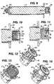
- FIG: 5shows a cap assembly 80 proximate the chamber 64 of the housing 60 and FIG. 6 shows the cap assembly 80 positioned within the chamber 64.
- the cap assembly 80has a cap 82 having a wall 83 defining a chamber 84 containing an absorbent material 86 such as a sponge.
- the sponge 86in a preferred form of the invention, is wetted or soaked with an agent such as an antiseptic, anticoagulant or antimicrobial ("antiseptic solution”) and can be selected from the locking and flushing solutions set forth below or the antiseptic solutions set forth below.
- the cap 82has an interior surface 87 with a set of threads 88 for mating with a set of threads on the access site 38.
- FIGS. 7 and 8show the cap assembly 80 sealed with a foil material or lid stock material 68 which can be attached to the flange 70 by any suitable method such as by adhesives or by conductive or inductive heat sealing techniques.
- FIG. 7shows the antiseptic cap piston assembly 12
- FIG. 8shows the antiseptic cap equipped piston assembly 12 inserted into the chamber of the syringe barrel 14 to define the antiseptic cap equipped piston and syringe barrel assembly 10.
- FIGS. 3 and 4show one possible method for utilizing the cap assembly 80 by docking with the access device 38.
- FIG. 3shows the lid stock 68 pealed away from the flange 70 and
- FIG. 4shows docking the antiseptic cap assembly 80 to the valve 39.
- the syringe barrelis rotated clockwise or counterclockwise to engage the threads 88 of the antiseptic cap assembly 80 with the threads of the access site 38. After engagement, the syringe barrel 14 will be moved away from the access site 38 and the antiseptic cap assembly 80 will slide outward from the housing 60 and remain docked to the access site 38.
- the antiseptic cap assembly 80can remain docked to the valve 39 of the access site 38 for any suitable period of time from a few minutes to numerous hours.
- the tubing or catheter 41is sealed to block the ingress into the catheter of pathogens and contaminants and a portion of the access site 38 is exposed to the antiseptic material in the sponge 86.
- the present inventionprovides a mechanism associated with the assembly 10 for preventing the rotation of the antiseptic cap assembly 80 with respect to the plunger assembly 14 and more preferably a mechanism on either the plunger assembly or on the antiseptic cap assembly 80 to prevent relative rotational movement between the antiseptic cap assembly 80 and the plunger assembly 12.
- the mechanism for preventing relative rotation of the antiseptic cap assembly 80 with respect to the plunger assembly 12has mating portions on both parts that when assembled cooperatively engage one another to prevent relative rotation. It is also contemplated that a separate mechanism, device or member could be used to lock the two parts together to achieve this purpose.
- FIGS. 5 , 9-11show exemplary structures for locking the antiseptic cap assembly 80 inside the housing 60 so that these parts rotate together and one part does not rotate in a direction or at a rate different from that of the other part.
- FIGS. 15-18show exemplary structures for interlocking the antiseptic cap plunger assembly 12 with the syringe barrel 14.
- the housing 60will have a feature or structure that forms an interference fit with an external surface 83 of the antiseptic cap 80. Even more preferably, an internal surface 63 of the side wall 62 of the housing 60 will have a feature or structure to form an interference fit with a portion of the antiseptic cap assembly 80. In another preferred form of the invention the antiseptic cap assembly 80 will have a feature to form an interference fit with the housing 60 and even more preferably the outer surface 83 of the antiseptic cap 80 will have a feature to contact the inner surface 63 of the housing side wall 62.
- FIG. 5shows one preferred form of the invention having a plurality of circumferentially spaced and axially extending ribs 100 on the internal surface 63 of the housing side wall 62 (internal ribs 100 ) for engaging the wall 83 of the antiseptic cap 82 to lock the cap assembly 80 in place to prevent rotation of the cap assembly 80 when positioned inside the housing 60.
- the internal ribs 100extend from a bottom wall 102 up to an intermediate height of the housing sidewall 62.
- the internal ribs 100will have a height roughly equal to a height of the cap 82.
- a plurality of internal slots 108are defined between each set of adjacent internal ribs 100.
- the internal ribs 100in a preferred form of the invention, will have a width that tapers inwardly from proximate the bottom wall 102 to a top 104 of the internal ribs 100 so that the width of the internal ribs decrease from a bottom 106 of a rib to the top 104 of the rib.
- the top of the internal ribs 100have a generally arcuate profile to act as a lead-in during insertion of the antiseptic cap assembly 80 into the housing 60.
- the internal ribs 100will terminate short of a top 113 of the housing sidewall 62 to define an annular gap 111 between the top of the rib 104 and the top 113. Also, extending radially inwardly from the internal surface 63 of the cap 82 is a detent 109 positioned proximate a top portion 113 of the side wall 62.
- the antiseptic cap 82has a plurality of circumferentially spaced and axially extending ribs 120 extending along an external surface 121 of the wall 83 of cap 82 (external ribs 120 ).
- the external ribs 120extend between an annular flange 123 at a proximal end 124 of the cap 82 to a position proximate a distal end 126 of the cap 82.
- the external ribs 120are dimensioned for engaging a portion of the interior wall surface 63 of the housing 62 to prevent relative rotation of the cap assembly 80 and the plunger assembly 12. Spacing between the external ribs define a plurality of external slots 122 between each adjacent pair of external ribs 120.
- each of the external ribs 120are positioned within an internal slot 108 and each of the internal ribs 100 are positioned within an external slot 122 to lock together these parts to assure that the cap rotates in the same direction as the plunger rod assembly 12.
- FIGS. 6 and 11also show that when the cap 82 is positioned within the housing 60, the detent 109 contacts the annular flange 123 to hold the cap assembly 80 in the plunger housing chamber 64 to prevent or resist inadvertent dropping of the cap assembly 80 from the housing chamber 64 prior to docking of the cap assembly 80 with the access site 38.
- FIGS. 12-14show several embodiments of gripping surfaces on the housing 60 (with lid stock 68 removed) to facilitate use of the assembly 10 or the plunger assembly 12.
- FIG. 12shows axially extending and circumferentially spaced protuberances 130 on an outer surface of the wall 62.
- the protuberances 130can have numerous different cross-sectional shapes including circular, polygonal, oval and irregular and, in a preferred form of the invention, extend from the flange 70 to a bottom of the housing.
- FIG. 13shows a housing 60 that has no flange 70 and has protuberances 130 on the wall 62 extending substantially the entire height of the housing 60.
- FIG. 14shows a housing 60 where the outer surface of the wall 62 is relatively smooth but as a series of circumferentially spaced and axially extending protuberances 130 on a circumferential edge of the flange 70.
- the optional plunger assembly 12 and syringe barrel 14 locking feature or structurecan be positioned alone on the plunger assembly 12, or alone on the syringe barrel 14 or have cooperating structures on both the plunger assembly 12 and the syringe barrel 14. It is also contemplated that a separate mechanism, device or member could be used to lock the two parts together to achieve this purpose.
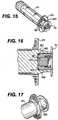
- FIGS. 15-18show various embodiments for the optional feature of locking the plunger assembly 12 from rotational motion with respect to the syringe barrel 14.
- a wing 150extending axially along an outside surface of the housing side wall 62 engages a tooth 152 positioned on an interior surface of the syringe barrel 14 at its proximal end 20.
- the plunger assembly 12will have more than one wing 150 with each wing being circumferentially spaced from the other.
- the plunger assemblywill have four wings 150 spaced 90 degrees from one another.
- the syringe barrel 14will have a plurality of circumferentially spaced teeth 152.
- each of the wings 150will extend into a tooth 152 to prevent rotation of the plunger assembly 12 with respect to the syringe barrel 14.
- FIG. 18shows another embodiment of a locking feature to prevent rotation of the plunger assembly 12 with respect to the syringe barrel 14 and also prevents relative translational motion of the parts.
- an annular protuberance 160positioned on an interior surface of the syringe barrel at is proximal end 20 engages an annular detent 162 on an outside surface of the plunger rod.
- FIGS. 19 and 20show an antiseptic cap equipped plunger assembly 12 and non-refluxing syringe assembly 170.
- Non-refluxing syringesare well known in the art and there are numerous methodologies for reducing reflux while accessing the access site of a central venous catheter.
- the annular flange 70 of the plunger assembly 12abuts the flange 24 of the syringe barrel prior to the piston 50 contacting an interior surface of the syringe distal end wall 30.
- FIGS. 22a, bshow a stand-alone antiseptic cap assembly 200 having three circumferentially spaced ribs 120 for grasping by the hand of a user of the cap assembly.
- FIG. 22ashows the cap 82 without an absorbent material 86 and
- FIG. 22bshows the cap with an absorbent material.
- the cap 200can be used for the same purposes of the cap assembly 80 described above but will be used by hand. All other features of the cap 200 are essentially the same as described about with the exception that the cap 200 does not have to be dimensioned to fit within a chamber carried by a syringe plunger.
- FIGS. 23 and 24show varying frequency of ribs 120 and varying shapes and sizes.
- FIG. 25shows the cap 200 proximate the access site 38 and FIGS. 26 and 27 show the cap 200 docked to the access site 38.
- a suitable absorbent material 86includes medical grade materials capable of storing and releasing an antiseptic liquid, or liquid having other medical purposes, and includes materials such as sponges, rupturable capsules and other materials or devices capable of serving this purpose.
- Suitable spongescan include any sponge suitable for use for medical purposes and can be naturally occurring or synthetic. The sponges can be die cut into suitable shapes or can be molded into the desired shape. It is desirable that the sponge 86 be attached to the antiseptic cap 82 to prevent the sponge 86 from inadvertently falling out of the cap 82.
- FIG. 28shows the sponge 86 is captured between an annular wall 202 and a disc 204 attached to the cap 82 by any suitable method such as ultrasonic or vibrational welding or other techniques well known in the art.
- FIGS. 29 and 30show a variation on the cap assembly 200 of FIG. 28 .
- the spongeis retained in the cap 82 with a plastic sheet 206 heat welded to the cap.
- the spongeis attached by an adhesive or by other method to form an assembly which is then attached to the cap.
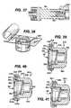
- FIGS. 31a, bshow the cap 200 having a coaxially disposed and axially extending actuating post 220 circumferentially surrounded by a sponge 86 having a centrally positioned hole to fit over the post 220.
- FIG. 31ashows the cap 200 in initial engagement with the access site 38 and
- FIG. 31bshows the cap threaded onto the access site 38 and the actuating post opens the valve 39 and antiseptic fluid is allowed to flow into the valve.
- FIGS. 32-34show varying shaped sponges that, in one preferred form of the invention, were molded into various desirable shapes.
- the sponge of FIG. 34has a central opening 230 to facilitate attaching the sponge to the cap and to filling the sponge with antiseptic, anticoagulant or other suitable fluids set forth above.
- FIG. 35shows the cap having a centrally disposed energy director 231, an ultrasonic welder 232 being brought into cooperative engagement with the sponge on a side of the sponge opposite the energy director 231. By applying ultrasonic energy the energy director 231 melts and attaches the sponge to the cap.
- FIG. 36shows a filling device 240, having a lumen 242 and a dispensing head 244 in fluid communication with a source of antiseptic, anticoagulant or the like for dispensing a metered amount of such fluid into the interior portion of the sponge.
- FIG. 37shows an alternative embodiment of the antiseptic cap 200 where the sponge is replaced by a antiseptic coating on the actuating post 220.
- FIG. 38shows the antiseptic cap 200 positioned in a blister pack 233 prior to sealing the blister pack.
- FIG. 39shows an antiseptic cap 300 with a thread cover 302.
- the thread cover 302can be part of any of the antiseptic caps discussed herein.
- the thread cover 302is made of a deformable material capable of flexing upon application of moderate force applied by hand.
- the thread cover 302is made from a polymeric containing material and more preferably a polymeric material having a modulus of elasticity of less than 20,000 psi..
- the polymeric materialwill be an elastomer or plastomer or like material.
- the thread cover 302enhances the connection between the antiseptic cap 300 and a device such as a valve or other access devices 38.
- the thread cover 302provides a physical barrier to the ingress of pathogens, dust or other contaminants through the mating threads of the antiseptic cap 300 and the access device or valve to which it is docked.
- the thread cover 302also serves to retain antiseptic fluids from the antiseptic cap 300 from leaking out through the threads.
- the thread covercan be made a part of the antiseptic cap 300 using techniques well known in the art such as overmolding, or by attaching as a separate part using welding techniques such as heat conductive welding, heat induction welding, vibrational welding, stretch or friction fit, or by using a suitable adhesive.
- the thread cover 302can provide a universal fit to most commercially available valves, connectors and access devices, or the thread cover 302 can be customized to dock with a particular access device.
- FIG. 39shows, as is described above, the antiseptic cap 300 has an annular wall 305 having a first end 306 and a second end 320 with the first end having a greater diametrical dimension than the second end.
- the annular walldefines a central chamber 322 having an open end 323.
- the chamber 322will have a sponge 86 positioned therein as shown in FIG. 5 and 6 above, although it is not shown in FIG. 39 .
- the thread cover 302is shown attached by an optional bonding layer 304 to the first end 306 of the annular wall 305.
- the thread cover 302has a first leg 308 and a second leg 310.
- the first leg 308extends parallel to the annular wall 305 and the second leg 310 extends radially inwardly from the annular wall 305 in a direction transverse to the first leg 308 and across a portion of the open end 323 and defines a central opening 312, having a reduced diameter when compared to the open end 323, into the chamber 322.
- the second leg 310terminates at a distal end 330 with a rounded outer surface 332.
- FIG. 40shows an alternative embodiment of the antiseptic cap 300 having the thread cover 302 having both the first and second legs 308, 310 attached to the first end 306 of the annular wall 305 through bonding layers 304 a,b.
- a top surface 340 of the first end 306is shown having the same thickness or diametrical dimension as the remainder of the first end but it is contemplated the top surface could have a radially extending flange 123 as shown in FIG. 5 .
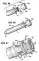
- FIG. 41shows an alternative embodiment of the antiseptic cap 300 that differs from the antiseptic cap shown in FIGS. 39 and 40 by not including a counterbore 336 shown in these figures.
- the counterbore 336provides a chamber of reduced diameter and, therefore, will form a tighter fit with access devices with a more narrow outer diameter when compared to the cap shown in FIG. 41 which does not include the counterbore.
- Thisis just one example of the modifications that can be made to the geometry of the antiseptic cap to enhance the connection between the cap and an access site.
- FIGS. 42a,bshow front and back views of the antiseptic cap 300 with the thread cover 302 connected to a Cardinal SMART SITE access site 350.
- FIGS. 43 a,bare perspective front and back views of the antiseptic cap without the thread cover 302 connected to the Cardinal SMART SITE access site.
- FIGS. 44 a,bare perspective front and back views of the antiseptic cap 300 with the thread cover 302 connected to a Hospira (ICU) C1000 Clave access device 352.
- FIGS. 45 a,bare perspective front and back views of the antiseptic cap, without a thread cover 302, connected to the Hospira (ICU) C1000 Clave access device.
- FIGS. 46 a,bare perspective front and back views of the antiseptic cap 300 with the thread cover 302 connected to a B. Braun ULTRASITE access device 354.
- FIGS. 47 a,bare perspective front and back views of the antiseptic cap without the thread cover 302 connected to the B. Braun ULTRASITE access device.
- FIGS. 48 a,bare perspective front and back views of the antiseptic cap with the thread cover 302 connected to a Rymed INVISION PLUS access device; 356.
- FIGS. 49 a,bare perspective front and back views of the antiseptic cap without the thread cover 302 connected to a Rymed INVISION PLUS access device.
- FIGS. 50-52show various embodiments of the thread cover 302.
- FIG. 50differs from FIG. 51 in that the second leg 310 extends farther across the opening of the chamber in FIG. 51 than shown in FIG. 50.
- FIG. 52shows another embodiment of the thread cover 302 having a segmented second leg 310 a,b. This embodiment may be desirable to provide a more effective seal for certain access devices.
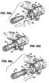
- FIG. 53shows an exploded view of an alternative embodiment 400 of the syringe barrel assemblies 10, discussed above, incorporating a cap holder 402 into the system of parts.
- the alternative assembly and system 400has an antiseptic cap and cap holder equipped plunger assembly 12', a syringe barrel 14, an antiseptic cap 82 (shown with an optional thread cover 302 ), an absorbent material 86, and peelable lid stock 68.
- FIG. 54shows an exploded view of an antiseptic cap holder assembly 404 including the cap holder 402 with the antiseptic cap assembly 80 positioned within a chamber 406 of the cap holder 402. This embodiment 400 allows for the separate manufacture, assembly, and sterilization of the assembly 400 from the plunger assembly and the syringe barrel.
- the cap holder 402has a proximal and distal ends 408, 410, and an inner wall surface 412 and an outer wall surface 414, an opening 416 into the chamber 406, and a radially outwardly extending flange 418 circumjacent the opening 416 and extending from the proximal end 408 of the cap holder 402.
- the cap holder 402will also have an optional bottom wall 419.
- the cap holder 402 or the antiseptic cap 82will have a structure, element or the like that prevents the relative rotation of the cap holder 402 and the antiseptic cap 82 until the antiseptic cap assembly 80 is securely docked to the access device 38.
- the cap holder 402 or the plunger assembly 12'will have a structure, element or the like for preventing the relative rotation of the cap holder 402 and the plunger assembly 12' until the antiseptic cap assembly 80 is securely docked to the access device 38. Any of the anti-rotation devices discussed above to stop the rotation of the antiseptic cap assembly 80 with the plunger assembly 12 would be suitable for these purposes. Also, it is contemplated the devices discussed above in reference to FIGS. 15-21 to prevent the relative rotation of the plunger assembly 12 and the syringe barrel 14 could be incorporated into this embodiment 400.
- FIG. 53shows the inner wall surface 412 of the cap holder 402 carries the internal ribs 100 and the internal slots 108 that interact with the external ribs and external slots 120, 122 of the cap 82 as is described above with respect to FIG. 5 .
- These structuresprevent or resist the relative rotation of the cap holder 402 with respect to the antiseptic cap assembly 80.
- ribsreferred to herein are structures that are raised or extend outward from a surface.
- slotsrefer to structures that extend below a surface or is defined between two ribs and is at a lower level than the ribs.
- FIG. 53also shows an interlocking structure for preventing the relative rotation of the cap holder 402, or the cap holder assembly 404, with respect to the plunger assembly 12'.
- the outer wall surface 414has a plurality of circumferentially spaced and axially extending ribs 420 defining slots 424 between each pair of adjacent ribs.
- the ribs 420are generally triangular in shape having a base portion 426 and an apex portion 428.
- the slots 424are oppositely-oriented triangularly shaped areas having slot base portions 430 extending between two adjacent rib apex portions 428 and slot apex portions 432 separating adjacent rib base portions 426.
- plunger ribs 434 and plunger slots 436On the internal wall surface 63 of the plunger chamber 64 are similarly shaped plunger ribs 434 and plunger slots 436.
- the ribs 420are dimensioned to fit within the plunger slots 436 and the slots 424 are dimensioned to fit over and receive the plunger ribs 434.
- the cap holder 402the cap holder assembly 404 or the plunger assembly 12' will have a structure, element or the like that resists the relative axial movement of these parts when the cap holder 402 or the cap holder assembly 404 is positioned fully within the plunger assembly 12'.
- the cap holder 402has an annular protuberance 440 that is dimensioned to fit within an annular groove 442 on the inner wall surface 414 of the cap holder and preferably extends in line with the base portions of the plunger ribs 434.
- a second locking structureis provided having a plurality of teeth 450 which extend axially outward from the outer wall surface 414 of the cap holder and are positioned in slots 424.
- the teethextend axially outwardly to a height beyond the height of the ribs 434.
- the teeth 450can be positioned in one or more of the slots or in each of the slots 424 or in alternating slots or, as is shown, circumferentially spaced 90° from one another.
- the teeth 450preferably are positioned at an intermediate portion, between the base and the apex, of a slot 424.
- the teeth 450are dimensioned to fit within a segmented annular groove 452 that extends circumferentially about the inner surface 412 crossing through the plunger ribs 434 at an intermediate portion, between the base and the apex, of the plunger ribs 434.
- FIGS. 56a,b,crespectively show the assembly 400 in a ready-for-use position, docked position, and used position.
- the assembly 400is used in essentially the same fashion as described above with respect to FIGS. 3 and 4 except that when the assembly 400 is in the used position the cap holder 402 remains in the plunger assembly 12'.
- the syringe barrel and plungercan be fabricated from any material suitable for its purpose and includes glass and polymeric material.
- Suitable polymeric materialsinclude, but are not limited to, homopolymers, copolymers and terpolymers formed from monomers such as olefins, cyclic olefins, amides, esters, and ethers.
- the polymeric materialmay be a blend of more than one polymeric material and can be a monolayer structure or a multilayer structure.
- the syringe barrel and the plungerare injection molded from a polypropylene material.
- FIGS. 59-61show a third embodiment 500 of an antiseptic cap equipped syringe plunger and barrel assembly with the antiseptic cap assembly 80 and lid stock 68 removed for clarity.
- the third embodiment 500provides for retrofitting an antiseptic cap assembly 502 to a standard plunger 504.
- the antiseptic cap 502has a first generally cylindrical outer wall 506 having a proximal end 508 and a distal end 510.
- the proximal end 508is removably or fixedly attached to a button 512 of the plunger 504.
- the proximal endhas an opening 514 dimensioned to fit about the button 512 and has a member for attaching to the button.
- the attaching memberincludes a plurality of circumferentially spaced, and axially inwardly directed tabs 516 extending from an inner wall surface 518 and the tabs engage a lower surface of the button 512 to attach the antiseptic cap assembly 502 to the plunger 504.
- the distal end of the antiseptic cap 504has a top annular flange 520 extending radially inwardly from the first cylindrical wall 506 and defines a generally circular opening 522.
- a second cylindrical wall 524extends axially downwardly from the top annular flange 520 and is coaxially disposed within the first cylindrical wall 506.
- a second set of tabscould be provided spaced axially away from the first set of tabs and the piston button 512 could be trapped between the two sets of tabs.
- attaching meanscould be used that are well know in the art and the attaching member shown is merely exemplary.
- the second cylindrical wall 524defines a chamber as is shown in greater detail in FIG. 5 above with the ribs and slots as described for engaging the antiseptic cap assembly 80 to prevent relative rotational movement and to resist relative axial movement of the parts when the antiseptic cap assembly 80 is fully inserted into the chamber. Further, it is contemplated adapting the plunger and syringe as described above to prevent or resist the relative rotational movement of the plunger with respect to the barrel.
- the piston 50can be formed from any suitable material including a polymeric material or a silicone material.
- the stoppercan be selected from a material with a desired durometer so that reflux is reduced when the stopper engages an inner surface of the distal end wall of the syringe barrel.
- Suitable locking an flush solutionsinclude a lower alcohol selected from ethanol, propanol and butanol.
- the locking solutioncan be a single lower alcohol or a blend of lower alcohols.
- Suitable locking solutionscan also include a lower alcohol with an antimicrobial and or an anticoagulant.
- Suitable locking solutionscan contain at least one lower alcohol in a range from 1% to 99% by volume and at least one other anti-microbial and/or anti-coagulant compound in a range from 1% to 99% by volume.
- the lower alcoholwill usually be in aqueous solution, typically at 1% to 99% by volume, usually from 5% to 95% by volume.
- the at least one other anti-microbialis selected from the group consisting of taurolidine and triclosan
- the at least one anti-coagulantis selected from the group consisting of riboflavin, sodium citrate, ethylene diamine tetraacetic acid, and citric acid.
- the syringe assembly 10will be pre-filled with one of the locking solutions and will be packaged by a manufacture and shipped to a health care provider.
- a cannula or needlewill be attached to the distal end of the barrel and placed into fluid communication with the fluid access site of an indwelling central venous catheter.
- the flush solutionwill be injected into the catheter to clean or lock the catheter.
- the cap assembly 80will be removed from the plunger 17 and the cap will be docked to the fluid access site of the catheter.
- the antisepticis a solution a citrate salt and in another form of the invention the citrate salt solution is a hypertonic solution.
- hypertonicis used herein to refer to a fluid having an osmotic concentration and a density greater than the osmotic concentration and density of the blood of the patient.
- the antiseptic solutionpreferably comprises a citrate salt with a concentration range, in weight percent, of from about 1.5% to about 50% with an osmolality of about 300 to about 6400 mOsm. More preferably, the antiseptic solution comprises citrate salt in a concentration range of from about 10% to about 40%, yet more preferably, in a concentration range of from about 20% to about 30%.
- the antiseptic solutionis prepared to have a pH lower than that of the pH of the patient's blood.
- the citrate salt solutionmay be prepared to have a pH lower than about 6.5, more preferably, from about 4.5 to about 6.5.
- the citrate salt solutioncan include pharmaceutically acceptable agents such as sodium chloride and sodium heparin.
- the citrate salt solutioncan also include a variety of other antibacterial, antimicrobial and anticoagulant agents such as gentamicin, vancomycin, and mixtures of these agents. Additional anticoagulant agents include, for example heparin, urokinase, tissue plasminogen activation (tPA) and mixtures of these agents.
- citrate salt solutionand the included salts and other additives which are, within the scope of sound medical judgment, suitable for use in contact with tissues of humans and lower animals without undue toxicity, irritation, and allergic response. It is also typically necessary that a composition be sterilized to reduce the risk of infection.
- An antimicrobial agent containing antiseptic solution of the present inventionmay contain at least one alcohol, at least one antimicrobial agent and at least one chelator and/or anticoagulant.
- Various antimicrobial substances as disclosed herein and that are well known to one of ordinary skill in the artmay be combined with the locking solution in order to inhibit infection.
- the antimicrobial locking solution of the present inventionmay be use for filling or flushing a medical device such as an indwelling device such as an implanted catheter. Other medical devices that are contemplated for use in the present invention are disclosed herein.
- the antiseptic agentcan contain antibacterial agents such as those classified as aminoglycosides, beta lactams, quinolones or fluoroquinolones, macrolides, sulfonamides, sulfamethaxozoles, tetracyclines, treptogramins, oxazolidinones (such as linezolid), clindamycins, lincomycins, rifamycins, glycopeptides, polymxins, lipo-peptide antibiotics, as well as pharmacologically acceptable sodium salts, pharmacologically acceptable calcium salts, pharmacologically acceptable potassium salts, lipid formulations, derivatives and/or analogs of the above.
- antibacterial agentssuch as those classified as aminoglycosides, beta lactams, quinolones or fluoroquinolones, macrolides, sulfonamides, sulfamethaxozoles, tetracyclines, tre
- the aminoglycosidesare bactericidal antibiotics that bind to the 30S ribosome and inhibit bacterial protein synthesis. They are typically active against aerobic gram-negative bacilli and staphylococci. Exemplary aminoglycosides that may be used in some specific aspects of the invention include amikacin, kanamycin, gentamicin, tobramycin, or netilmicin.
- Suitable beta lactamsare selected from a class of antibacterials that inhibit bacterial cell wall synthesis.
- a majority of the clinically useful beta-lactamsbelong to either the penicillin group (penam) or cephalosporin (cephem) groups.
- the beta-lactamsalso include the carbapenems (e.g., imipenem), and monobactams (e.g., aztreonam).
- Inhibitors of beta-lactamasesuch as clavulanic acid and its derivatives are also included in this category.
- Non-limiting examples of the penicillin group of antibioticsthat may be used in the solutions of the present invention include amoxicillin, ampicillin, benzathine penicillin G, carbenicillin, cloxacillin, dicloxacillin, piperacillin, or ticarcillin, etc.
- cephalosporinsexamples include ceftiofur, ceftiofur sodium, cefazolin, cefaclor, ceftibuten, ceftizoxime, cefoperazone, cefuroxime, cefprozil, ceftazidime, cefotaxime, cefadroxil, cephalexin, cefamandole, cefepime, cefdinir, cefriaxone, cefixime, cefpodoximeproxetil, cephapirin, cefoxitin, cefotetan etc.
- beta lactamsinclude mipenem or meropenem which are extremely active parenteral antibiotics with a spectrum against almost all gram-positive and gram-negative organisms, both aerobic and anaerobic and to which Enterococci, B. fragilis, and P. aeruginosa are particularly susceptible.
- Suitable beta lactamase inhibitorsinclude clavulanate, sulbactam, or tazobactam.
- the antibacterial solutionsmay comprise a combination of at least one beta lactam and at least one beta lactamase inhibitor.
- Macrolide antibioticsare another class of bacteriostatic agents that bind to the 50S subunit of ribosomes and inhibit bacterial protein synthesis. These drugs are active against aerobic and anaerobic gram-positive cocci, with the exception of enterococci, and against gram-negative anaerobes. Exemplary macrolides include erythromycin, azithromycin, clarithromycin.
- Quinolones and fluoroquinolonestypically function by their ability to inhibit the activity of DNA gyrase. Examples include nalidixic acid, cinoxacin, trovafloxacin, ofloxacin, levofloxacin, grepafloxacin, trovafloxacin, sparfloxacin, norfloxacin, ciprofloxacin, moxifloxacin and gatifloxacin.
- Sulphonamidesare synthetic bacteriostatic antibiotics with a wide spectrum against most gram-positive and many gram-negative organisms. These drugs inhibit multiplication of bacteria by acting as competitive inhibitors of p-aminobenzoic acid in the folic acid metabolism cycle. Examples include mafenide, sulfisoxazole, sulfamethoxazole, and sulfadiazine.
- the tetracycline group of antibioticsinclude tetracycline derivatives such as tigecycline which is an investigational new drug (IND), minocycline, doxycycline or demeclocycline and analogs such as anhydrotetracycline, chlorotetracycline, or epioxytetracycline.
- tetracycline derivativessuch as tigecycline which is an investigational new drug (IND), minocycline, doxycycline or demeclocycline and analogs such as anhydrotetracycline, chlorotetracycline, or epioxytetracycline.
- Suitable streptogramin class of antibacterial agentsinclude quinupristin, dalfopristin or the combination of two streptogramins.
- Drugs of the rifamycin classtypically inhibit DNA-dependent RNA polymerase, leading to suppression of RNA synthesis and have a very broad spectrum of activity against most gram-positive and gram-negative bacteria including Pseudomonas aeruginosa and Mycobacterium species.
- An exemplary rifamycinis rifampicin.
- antibacterial drugsare glycopeptides such as vancomycin, teicoplanin and derivatives thereof.
- antibacterial drugsare the polymyxins which are exemplified by colistin.
- antibacterial agentssuch as prestinomycin, chloramphenicol, trimethoprim, fusidic acid, metronidazole, bacitracin, spectinomycin, nitrofurantion, daptomycin or other leptopeptides, oritavancin, dalbavancin, ramoplamin, ketolide etc. may be used in preparing the antiseptic solutions described herein.
- metronidazoleis active only against protozoa, such as Giardia lamblia, Entamoeba histolytica and Trichomonas vaginalis, and strictly anaerobic bacteria.
- Spectinomycinis a bacteriostatic antibiotic that binds to the 30S subunit of the ribosome, thus inhibiting bacterial protein synthesis and nitrofurantoin is used orally for the treatment or prophylaxis of UTI as it is active against Escherichia coli, Klebsiella-Enterobacter species, staphylococci, and enterococci.
- the antimicrobial agentis an antifungal agent.
- Some exemplary classes of antifungal agentsinclude imidazoles or triazoles such as clotrimazole, miconazole, ketoconazole, econazole, butoconazole, omoconazole, oxiconazole, terconazole, itraconazole, fluconazole, voriconazole, posaconazole, ravuconazole or flutrimazole; the polyene antifungals such as amphotericin B, liposomal amphoterecin B, natamycin, nystatin and nystatin lipid formualtions; the cell wall active cyclic lipopeptide antifungals, including the echinocandins such as caspofungin, micafungin, anidulfungin, cilofungin; LY121019; LY303366; the allylamine group of antifungals such as terbinafine.
- antifungal agentsinclude naftifine, tolnaftate, mediocidin, candicidin, trichomycin, hamycin, aurefungin, ascosin, ayfattin, azacolutin, trichomycin, levorin, heptamycin, candimycin, griseofulvin, BF-796, MTCH 24, BTG-137586, pradimicins (MNS 18184), benanomicin; ambisome; nikkomycin Z; flucytosine, or perimycin.
- the antimicrobial agentis an antiviral agent.
- antiviral agentsinclude cidofovir, amantadine, rimantadine, acyclovir, gancyclovir, pencyclovir, famciclovir, foscamet, ribavirin, or valcyclovir.
- the antimicrobial agentis an innate immune peptide or proteins.
- Some exemplary classes of innate peptides or proteinsare transferrins, lactoferrins, defensins, phospholipases, lysozyme, cathelicidins, serprocidins, bacteriocidal permeability increasing proteins, amphipathic alpha helical peptides, and other synthetic antimicrobial proteins.
- the antimicrobial agentis an antiseptic agent.
- antiseptic agentsinclude a taurinamide derivative, a phenol, a quaternary ammonium surfactant, a chlorine-containing agent, a quinaldinium, a lactone, a dye, a thiosemicarbazone, a quinone, a carbamate, urea, salicylamide, carbanilide, a guanide, an amidine, an imidazoline biocide, acetic acid, benzoic acid, sorbic acid, propionic acid, boric acid, dehydroacetic acid, sulfurous acid, vanillic acid, esters of p-hydroxybenzoic acid, isopropanol, propylene glycol, benzyl alcohol, chlorobutanol, phenylethyl alcohol, 2-bromo-2-nitropropan-1,3-diol, formaldehyde, glutaralde
- the antiseptic solutionincludes a basic reagent and a dye.
- the basic reagentmay be a guanidium compound, a biguanide, a bipyridine, a phenoxide antiseptic, an alkyl oxide, an aryl oxide, a thiol, a halide, an aliphatic amine, or an aromatic amine.
- the basic reagentis a guanidium compound.
- Non-limiting examples of guanidium compoundsinclude chlorhexidine, alexidine, hexamidine.
- the basic reagentis a bipyridine.
- One example of a bipyridineis octenidine.
- the basic reagentis a phenoxide antiseptic.
- the dyemay be a triarylmethane dye, a monoazo dye, a diazo dye, an indigoid dye, a xanthene dye, an anthraquinone dye, a quinoline dye, an FD&C dye.
- triarylmethane dyeinclude gentian violet, crystal violet, ethyl violet, or brilliant green.
- Other non-limiting examples of FD&C dyeinclude Blue No. 1 or Green No. 3.
- One non-limiting example of diazo dyesis D&C Red No. 17.
- An example of an indigoid dyeis FD&C Blue No. 2.
- An example of a xanthene dyeis FD&C Red No. 3; of an anthraquinone dye is D&C Green No. 6; and of an quinoline dye is D&C Yellow No. 1.
- antiseptic agentsthat may be used to prepare the amntimicrobial solutions of the invention are gendine, genlenol, genlosan, or genfoctol.
- antimicrobial agentsincluding one or more antibacterial agent, and/or one or more antifungal agent, and/or one or more antiviral agent, and/or one or more antiseptic agent, and/or combinations thereof.
- chelator agentsare contemplated as useful in preparing the antiseptic solutions of the invention. This includes chelators such as EDTA free acid, EDTA 2Na, EDTA 3Na, EDTA 4Na, EDTA 2K, EDTA 2Li, EDTA 2NH 4 , EDTA 3K, Ba(II)-EDTA, Ca(II)-EDTA, Co(II)-EDTACu(II)-EDTA, Dy(III)-EDTA, Eu(III)-EDTA, Fe(III)-EDTA, In(III-EDTA, La(III)-EDTA, CyDTA, DHEG, diethylenetriamine penta acetic acid (DTPA), DTPA-OH, EDDA, EDDP, EDDPO, EDTA-OH, EDTPO, EGTA, HBED, HDTA, HIDA, IDA, Methyl-EDTA, NTA, NTP, NTPO, O-Bistren, TT
- at least one anticoagulantsuch as heparin, hirudin, EGTA, EDTA, urokinase, streptokinase, hydrogen peroxide etc.
- alcoholsare contemplated as useful in the preparation of the instant antiseptic solution, and include any antimicrobially active alcohol.
- Non-limiting examples of alcoholsinclude ethanol, methanol, isopropanol, propylene glycol, benzyl alcohol, chlorobutanol, phenylethyl alcohol, and the like.
- the solutions of the instant inventioncan comprise various combinations of at least one alcohol, at least one antimicrobial agent, and at least one chelator/anticoagulant.
- the solution of the inventioncomprises at least one alcohol, at least one tetracycline and at least one chelator/anticoagulant.
- such an antimicrobial solutioncomprises ethanol, at least one tetracycline and EDTA or heparin.
- such a solutioncomprises ethanol, minocycline and EDTA or heparin.
- the concentration of minocyclineis 0.001 mg/ml to 100 mg/ml.
- the concentration of minocyclineis about 3 mg/ml.
- the concentration of EDTAis in the range of 10-100 mg/ml. In one embodiment of this aspect, the concentration of EDTA is about 30 mg/ml.
- the antiseptic solutionincludes a pharmacologically acceptable sodium salt, a pharmacologically acceptable calcium salt, a pharmacologically acceptable potassium salt and about one milligram per milliliter polyhexamethylene biguanide hydrochloride in an aqueous admixture.
- the solution of the inventionmay also contain a pharmacologically acceptable salt of lactic acid.
- One preferred antiseptic solutionincludes a pharmacologically acceptable sodium salt such as sodium chloride or the like in a concentration of between about 820 mg to about 900 mg, a pharmacologically acceptable calcium salt, such as calcium chloride dihydrate or the like in a concentration between about 30.0 mg to about 36.0 mg, a pharmacologically acceptable potassium salt, such as potassium chloride or the like in a concentration between about 28.5 to about 31.5 mg and about one milligram per milliliter polyhexamethylene biguanide hydrochloride in an aqueous admixture with one hundred milliliters of water for injection U.S.P.
- the solution of the inventionmay also include sodium lactate in a concentration between about 290 mg and about 330 mg in the one hundred milliliter aqueous admixture.
- the antiseptic solutioncontains an anticoagulant and a photo-oxidant.
- a photo-oxidantis selected that has an antiseptic effect.
- photo-oxidantis intended to refer to a compound (usually an organic dye) that has photo-oxidation properties, in which the compound exhibits an increased oxidizing potential upon exposure to radiant energy such as light.
- photo-oxidantalso refers to a composition that releases one or more electrons when struck by light.
- the photo-oxidantis methylene blue, which advantageously provides antibiotic and antifungal activity, and also provides a color to make the antiseptic solution clearly identifiable.
- other photo-oxidantsmay include Rose Bengal, hypericin, methylene violet, proflavine, rivanol, acriflavine, toluide blue, trypan blue, neutral red, a variety of other dyes or mixtures thereof. Therefore, in alternate aspects of the invention, one or more alternative photo-oxidants, preferably a colored photo-oxidant is used in accordance with the invention in place of methylene blue.
- the antiseptic solutionincludes a low viscosity antibacterial agent mixed with a viscosity increasing agent.
- antibacterial agentswhich may be used, in addition to those described above, comprise alcohols, chlorhexidine, Chlorpactin, iodine, tauroline, citric acid, and soluble citric acid salts, particularly sodium citrate, optionally mixed with water.
- Suitable viscosity increasing agentsinclude Carbopol, starch, methylcellulose, carboxypolymethylene, carboxymethyl cellulose, hydroxypropylcellulose, or the like.
- Carbopolis a cross-linked polyacrylic acid based polymer sold by Noveon, Inc. It is preferably neutralized to about pH 7 with a base material such as tetrahydroxypropyl ethylene diamine, triethanolamine, or sodium hydroxide.
- Derivatives of starchmay also be used, such as hydroxyethylstarch, hydroxypropylstarch, or starch having bonded organic acid ester groups, to improve compatibility with antibacterial agents such as alcohols, for example, ethanol or isopropanol.
- ester groupsmay be the reaction product of two to twelve carbon organic acids with the starch, for example.
- the elevated viscosity antiseptic solutionmay be created by the use of a fat emulsion, or other dispersions in water/alcohol of glycerol mono or di esters of fatty acids, or fatty acid esters of other polyols such as sugars having one or more bonded fatty acid groups per molecule. Analogous compounds with ether linkages may also be used.
- the fluid of this inventionmay also contain an effective amount of an antithrombogenic agent such as heparin, and a diluent such as water, along with other desired ingredients.
- an antithrombogenic agentsuch as heparin
- a diluentsuch as water
- the antiseptic solutioncontains a mixture of isopropyl alcohol and neutralized Carbopol, with other optional ingredients being present such as water, antithrombogenic agents such as heparin, and the like. Preferably, about 0.4 to 2 weight percent of Carbopol is present.
- Citric acidmay also be present as an antibacterial agent, either with or as a substitute for another anti-bacterial agent such as isopropyl alcohol or ethanol.
- the antiseptic solutionis a gel of an isopropyl alcohol, optionally with up to about 30 weight percent water, and about 2.2 weight percent hydroxypropylcellulose, to form a high viscosity antiseptic solution.
- the antiseptic solutioncontains carbohydrates and/or glucose degradation products.
- Suitable carbohydratesare chosen form the group of glucose and/or fructose.
- Suitable degradation productsinclude 3-deoxyglucosone (3-DG), acetaldehyde, formaldehyde, acetaldehyde, glyoxal, methylglyoxal, 5-hydroxymethyl-2-furaldehyde (5-HMF), 2-furaldehyde, and 3,4-dideoxyglucosone-3-ene (3,4-DGE).
- Suitable agents to be used in this embodiment of the antiseptic solutionincludes substances having anticoagulatory properties i.e., inhibitors of the coagulation cascade such as heparin of standard and low molecular weight, fractionated heparin, synthetic inhibitors in the coagulation cascade, Futhan as a broad protease inhibitor, complexing and chelating substances such as citrate, EDTA, EGTA, substances and mixtures used for preservation of blood products (platelets or plasma), CDPA (citrate, sodium phosphate, dextrose, adenine), synthetic or natural thrombin inhibitor substances.
- Other suitable additivesinclude fucosidan, riboflavin, vitamin E, alpha-tocopherol, folic acid and amino acids.
- antiinflammatory compounds and drugscould also be used, e.g. cortison, mycophenolic acid (MPA) and derivates thereof, sirolimus, tacrolimus and cyclosporin, diclofenac, etc.
- Inhibitory peptidescan also be used in the antiseptic solution such as defensins, (dermacidine), and others. Radicals, such as reactive oxygene species, NO-releasing systems or nitric oxide (NO), and peroxynitrite may also be used.
- a buffer composition masalso be included in the antiseptic solution, and in one preferred form of the invention, the buffer contains lactate, bicarbonate, pyruvate, ethyl pyruvate and citric acid in combination and mixtures including adjustment of pH by acetic acid, hydrochloric acid or sulphuric acid.
- viscosity enhancing additivesmay be added, such as lipids or lipidic substances (also to get water insoluble vitamins or complexes into solution), nutrients in high concentration density gradient e.g. aminoacid containing fluids, polyglucose, Icodextrin, pectine, hydroxyethyl starch (HES), alginate, hyaluronic acid, etc.
- the antiseptic solutions of the present inventioncan include Taurolidine and/or Taurultam to prevent clotting and Biofilm formation or the elements can be combined with other antimicrobial agents.
- One embodiment of the present inventionis a gel with thixotropic properties to keep the solution inside the antiseptic cap and not spill out during the time interval between uses. This is accomplished by making a hydrogel matrix as a drug delivery vehicle containing a biocompatible antimicrobial agent alone or with another active agent, which may be useful for particular purposes.
- the hydrogel matrixis biocompatible and, biodegradable in the bloodstream.
- the matrixcan be a hydrogel (e.g., pectin, gelatin, etc), a protein (e.g., collagen, hemoglobin, etc), a colloidal substance (e.g., serum albumin etc), an emulsion or other adjuvant.
- the matrixshall have structural integrity and be thixotropic.
- Thixotropyis a property, which is exhibited by certain gels. It is a property characterized by a solid or semisolid substance that when shaken, stirred or subject to high shear forces becomes fluid like and can flow and then returns to the semisolid state when the forces and/movement are stopped.
- the gelcould have the properties similar to that of the colloidal dispersion which resists movement, or flow until a high shear force is imparted to the fluid and then it flows easily.
- the preferred antimicrobialis Taurolidine, which can be added to the matrix as a micro particle powder, or encapsulated in liposomes, microspheres, or nanospheres. It should be appreciated that numerous active agents and drugs can be added to the thixotropic gel including sterileants, lysing agents (such as Urokinase), imaging enhancers, catheter surface modifiers, antibiotics and antimicrobial chemicals.
- a hydrogelcomprises a three-dimensional molecular network containing large quantities of water giving them good biocompatibility with material consistency that is soft solid-like with high diffusive properties to gases, chemicals and proteins.
- Suitable hydrogelsinclude natural polymers including serum albumin, collagen, or alginates, polyvinyl alcohol, poly (ethylene oxide) or poly (hydroxyethylene) and polyelectrolytes, such as poly(acrylic acid), poly(styrene sulfonate), and carboxymethylcellulose (CMC).
- One preferred form of the antiseptic solutionincludes Taurolidine with Salicylic acid or Sodium Salicylate in an aqueous solvent.
- Salicylic Acid and Sodium Salicylateare drugs that have been used with antibiotic locks in catheters to enhance the biocidal action of the antibiotic alone and to inhibit the attachment of microbes to surfaces. This last attribute is especially important because the initiation of a Biofilm expression and growth require that the individual bacteria must first attach themselves to the underlying surface. By stopping attachment, Biofilm formation is blocked.
- Sodium salicylatehas been demonstrated to have remarkable antibacterial activity, including the ability to enhance the activities of certain antibiotics. This drug inhibits adherence, growth and Biofilm formation.
- EDTAethylene diamine tetraacetic acid
- antiseptic solutions of the present inventionare safe for human administration and are biocompatible and non-corrosive. They may also have anticoagulant properties and are thus useful for preventing and/or treating a variety of catheter-related infections.
- antiseptic solutions of the present inventionhave at least four, and preferably at least five, of the following properties: anticoagulant properties; inhibitory and/or bactericidal activity against a broad spectrum of bacteria in a planktonic form; inhibitory and/or fungicidal activity against a spectrum of fungal pathogens; inhibitory and/or bactericidal activity against a broad spectrum of bacteria in a sessile form; inhibitory activity against protozoan infections; inhibitory activity against Acanthamoeba infections; safe and biocompatible, at least in modest volumes, in contact with a patient; safe and biocompatible, at least in modest volumes, in a patient's bloodstream; and safe and compatible with industrial objects and surfaces.
- the antiseptic solutioncan have a pH higher than physiological pH such as a pH of >
- the antiseptic solutioncontain a sodium EDTA salt (or combination of sodium salts) in solution at a pH in the range between 8.5 and 12.5 and, in another embodiment, at a pH of between 9.5 and 11.5 and, in yet another embodiment, at a pH of between 10.5 and 11.5.
- a sodium EDTA saltor combination of sodium salts
- EDTA saltmay refer to a single salt, such as a di-sodium or tri-sodium or tetra-sodium salt, or another EDTA salt form, or it may refer to a combination of such salts.
- the composition of EDTA salt(s)depends both on the EDTA salts used to formulate the composition, and on the pH of the composition.
- the sodium EDTA saltsare predominantly present in both the tri-sodium and tetra-sodium salt forms.
- the antiseptic solutioncontains a combination of at least the tri-sodium and tetra-sodium salts of EDTA, and more preferably solutions containing at least 10% of the EDTA in the composition is present in the tetra-sodium salt form. In yet another embodiment, at least 50% and, more preferably at least 60%, of the EDTA in the composition is present in the tri-sodium salt form.
- EDTA solutions of the present inventionare preferably provided in a sterile and non-pyrogenic form and may be packaged in any convenient fashion.
- the compositionsmay be prepared under sterile, aseptic conditions, or they may be sterilized following preparation and/or packaging using any of a variety of suitable sterilization techniques.
- desired antiseptic solutions of the present inventionare formulated by dissolving one or more EDTA salt(s) in an aqueous solvent, such as purified water, to the desired concentration and adjusting the pH of the EDTA salt solution to the desired pH.
- the antiseptic solutionmay then be sterilized using conventional means, such as autoclaving, UV irradiation, filtration and/or ultrafiltration, and other means.
- the preferred osmolarity range for EDTA solutionsis from 240-500 mOsM/Kg, more preferably from 300-420 mOsm/Kg.
- the solutionsare preferably formulated using USP materials.
- Antiseptic solutions containing sodium salts of EDTA other than tri- and tetra-sodium salts, such as di-sodium EDTAis also contemplated.
- di-sodium EDTA solutionscan be used but such solutions have a lower pH in solution than the desired pH range of compositions of the present invention but, upon pH adjustment to the desired range using a pH adjustment material, such as sodium hydroxide, sodium acetate, and other well-known pH adjustment agents, EDTA solutions prepared using di-sodium salts are converted to the preferred combination di- and/or tri- and/or tetra-sodium salt EDTA solutions of the present invention.
- antiseptic compositionsconsisting of a mixture of primarily tri-and tetra-sodium EDTA is provided by dissolving di-sodium EDTA in an aqueous solution, 3%-5% on a weight/volume basis, and adding sodium hydroxide in a volume and/or concentration sufficient to provide the desired pH of >8.5 and ⁇ 12.0.
- Antibacterial enzymerefers to any proteolytic, pore-forming, degradative or inhibitory enzyme that kills or damages a bacterial species or particular strain thereof. The result may be achieved by damaging the cell wall of the bacteria, disrupting cell membranes associated with the cell wall or within the bacteria, inhibiting protein synthesis within the bacteria, disrupting the sugar backbone, or by any other mechanism attributed to a peptide or protein considered by those skilled in the art to be an antibacterial enzyme.
- the enzymemay be a natural, wild-type enzyme, modified by conventional techniques, conjugated to other molecules, recombinantly expressed, or synthetically constructed.
- Lysostaphinis important because it is effective in the treatment of staphylococci and biofilms formed therefrom.
- Lysostaphinand "lysostaphin analogues” are defined as including lysostaphin (wild type), any lysostaphin mutant or variant, any recombinant, or related enzyme (analogue) or any synthetic version or fragment of lysostaphin (whether synthetic or otherwise) that retains the proteolytic ability, in vivo and in vitro, to cleave the cross-linked polyglycine bridges in the cell wall peptidoglycan of staphylococci.
- the enzymesmay be generated by post-translational processing of the protein (either by enzymes present in a producer strain or by means of enzymes or reagents introduced at any stage of the process) or by mutation of the structural gene. Mutations may include site deletion, insertion, domain removal and replacement mutations.
- the lysostaphinmay be synthetically constructed, expressed in mammalian cells, insects, bacteria, yeast, reptiles or fungi, recombinantly expressed from a cell culture or higher recombinant species such as a mouse, or otherwise. This would include the activity-retaining synthetic construction including synthetic peptides and polypeptides or recombinant expression of portions of the lysostaphin enzyme responsible for its activity against staphylococci as part of a larger protein or peptide, include chimeric proteins, containing the active sites of one or more other antibacterial enzymes that are effective either against staphylococci or other biofilm-forming bacteria species.
- the antibacterial enzymesmay also be coated on the surface of the devices described herein by immersion of the device in a solution of the enzyme for a length of time sufficient to form a biofilm-formation inhibiting coating of the enzyme on the susceptible surface. Even the most minimal concentration of enzyme will confer some protection. Typically, a concentration of from about 10 ⁇ g/ml to about 100 mg/ml can be used. With device surfaces, the coatings may also be formed by covalent attachment of the enzyme thereto.
- the devices described hereincan be coated with an antiseptic coating by any suitable technique such as immersion of the part into an antiseptic solution, by spray coating the part with the antiseptic solution, by blending the antiseptic solution or material into the polymeric material used to fabricate the device.
- a quantity of physiological, antimicrobial metal compoundis added to the resin for direct molding of an article.
- Physiological, antimicrobial metalsare meant to include the precious metals, such as silver, gold and platinum, and copper and zinc.
- Physiological, antimicrobial metal compounds used hereininclude oxides and salts of preferably silver and also gold, for example: silver acetate, silver benzoate, silver carbonate, silver citrate, silver chloride, silver iodide, silver nitrate, silver oxide, silver sulfa diazine, silver sulfate, gold chloride and gold oxide.
- Platinum compoundssuch as chloroplatinic acid or its salts (e.g., sodium and calcium chloroplatinate) may also be used.
- compounds of copper and zincmay be used, for example: oxides and salts of copper and zinc such as those indicated above for silver.
- Single physiological, antimicrobial metal compounds or combinations of physiological, antimicrobial metal compoundsmay be used.
- Preferred physiological, antimicrobial metal compounds used in this inventionare silver acetate, silver oxide, silver sulfate, gold chloride and a combination of silver oxide and gold chloride.
- the particles of the silver compoundsare sufficiently able to be extracted to form a zone of inhibition to prevent and kill bacteria growth.
- the devices hereinare impregnated with triclosan and silver compounds or triclosan and chlorhexidine.
Landscapes
- Health & Medical Sciences (AREA)
- Heart & Thoracic Surgery (AREA)
- Animal Behavior & Ethology (AREA)
- General Health & Medical Sciences (AREA)
- Biomedical Technology (AREA)
- Engineering & Computer Science (AREA)
- Hematology (AREA)
- Life Sciences & Earth Sciences (AREA)
- Veterinary Medicine (AREA)
- Anesthesiology (AREA)
- Public Health (AREA)
- Pulmonology (AREA)
- Epidemiology (AREA)
- Vascular Medicine (AREA)
- Infusion, Injection, And Reservoir Apparatuses (AREA)
- Media Introduction/Drainage Providing Device (AREA)
- Materials For Medical Uses (AREA)
- External Artificial Organs (AREA)
Description
- The present invention relates to an antiseptic cap having a thread cover to enhance a seal between the cap and an access site to a body of a mammal. More particularly the invention relates to an antiseptic cap for attaching to an access site of an indwelling, central venous catheter and having a thread cover to enhance a seal between the cap and the access site.
- Catheters are widely used to treat patients requiring a variety of medical procedures. Catheters can either be acute, or temporary, for short-term use or chronic for long-term treatment. Catheters are commonly inserted into central veins (such as the vena cava) from peripheral vein sites to provide access to a patient's vascular system. Catheters offer many advantages for patients; for example, chronic catheters provide ready access without repeated punctures or repeated vessel cannulation for administration of large volumes of fluids, nutrients and medications and for withdrawal of blood on an intermittent basis. With respect to the use of catheters for infusion of fluids, examples include the infusion of drugs, electrolytes or fluids used in chemotherapy. In chemotherapy, catheters are used for infusion of drugs on an intermittent basis, ranging from daily to weekly. Another example includes the use of catheters in hyperalimentation treatment, wherein the catheters are usually used for infusion of large volumes of fluids.
- For hemodialysis, catheters are commonly used--usually three times per week--for aspiration of blood for dialysis treatment and rapid return of the blood to circulation after treatment. Although a preferred mode of vascular access for a hemodialysis patient involves using an arteriovenous (AV) fistula of either the upper or lower extremities or an arteriovenous "bridge" graft (typically utilizing PTFE), use of these access devices is not always possible or desirable. When either of these modes of vascular access is not available, for example, due to a paucity of adequate blood vessels for creation of AV "shunts" or due to nonoptimally functioning established AV shunts, a large bore venous line catheter is typically required for hemodialysis. Catheters used for hemodialysis usually include two relatively large diameter lumens (usually molded as one catheter) for aspiration and rapid return of blood required during the hemodialysis procedure. One lumen of such a catheter is used for aspiration, or removal, of blood, while the other lumen is used for returning the blood to the patient's bloodstream.
- Catheter connections, such as, for example, connections of catheters to dialysis machine tubing, to IV line tubing, to infusion ports and to catheter caps, which are used to seal the end of a catheter to protect the sterility of the catheter and prevent fluid loss and/or particle contamination, are most often made utilizing the medical industry's standardized Luer taper fittings. These fittings, which may either be male couplings or female couplings, include a tapered end of standardized dimensions. Coupling is made by the press-fit of mating parts. A threaded lock-fit or other type of securing mechanism is commonly utilized to ensure the integrity of the pressure fit of the Luer fittings.
- Catheters, especially chronic venous catheters, provide challenges in their use. One such challenge is that such catheters can become occluded by a thrombus. In order to prevent clotting of catheters in blood vessels between uses, such as, for example, between dialysis treatments when the catheter is essentially nonfunctioning and dwells inside a "central" vein (i.e. superior vena cava, inferior vena cava, iliac, etc), the lumens of the catheter are often filled with a lock solution of a concentrated solution of the commonly used anticoagulant, heparin (up to 10,000 units of heparin per catheter lumen).
- As used herein, the terms "lock solution" or "locking solution" refer to a solution that is injected or otherwise infused into a lumen of a catheter with the intention of allowing a substantial portion of the lock solution to remain in the lumen and not in the systemic blood circulation until it is desired or required to access that particular lumen again, typically for additional treatment, i.e., infusion or withdrawal of fluid. In addition, attention has been given to the development of alternative lock solutions with the goal of improving the patency rates of vascular catheters. For example, lower-alcohol containing locking solutions are under development wherein the lower alcohols include ethanol, propanol and butanol. Anti-microbial and or anticoagulant additives can optionally be added to the lower-alcohol containing locking solution. Preferably the lock solution can remain in the lumen for a desired amount of time lasting from about 1 hour to 3 or 4 days or longer.
- For the reasons set forth above, significant care must be taken when infusing medications, nutrients and the like into a catheter, and when "locking" a catheter between uses, to minimize the risks associated with an indwelling catheter, including the risk of thrombosis or clotting, the risk of excessive anticoagulating and the risk of infection. Syringes are typically used to administer the required amount of catheter lock solution (determined by the catheter manufacturer) into an indwelling catheter after a given use. Flush procedures also require that care be taken to prevent blood reflux into the catheter. Reflux in I.V. therapy is the term commonly used to describe the fluid that is drawn back into the catheter after a flush procedure. The concern is that the reflux fluid contains blood or solution that could cause the catheter to occlude. To ensure that reflux does not occur, flush procedures suggest two techniques: 1) at the end of the flush solution delivery, the user maintains pressure on the syringe plunger while clamping the I.V. line; or 2) while delivering the last 0.5 ml of flush solution disconnect the syringe from the I.V. port or clamp the I.V. line. Either technique maintains positive pressure on the fluid in the catheter to prevent reflux of fluid and blood.
- In light of the above-described problems, there is a continuing need for advancements in catheter lock techniques, devices and procedures to improve the safety and efficacy of catheter locking procedures and of overall patient care.
US 5,554,135 A discloses sterile medical injection ports and covering apparatus for hospital and home use.DE 89 06 628 U1 discloses a luer nut for catheters.- According to an aspect of the invention, there is provided a cap as recited in Claim 1. Optional features of the invention are cited in the dependent claims.
FIG. 1 is a perspective view of an antiseptic cap equipped plunger and syringe barrel assembly prior to connection of a syringe tip to an access point to a central venous catheter;FIG. 2 is a perspective view of an antiseptic cap equipped plunger and syringe barrel assembly with the syringe tip connected to an access point to a central venous catheter;FIG. 3 is a perspective view of an antiseptic cap equipped plunger and syringe barrel assembly prior to connection of the antiseptic cap to an access point to a central venous catheter;FIG. 4 is a perspective view of an antiseptic cap equipped plunger and syringe barrel assembly after connection of the antiseptic cap to an access point to a central venous catheter;FIG. 5 is a perspective view assembly drawing of an antiseptic cap equipped plunger;FIG. 6 is a perspective view of an antiseptic cap equipped plunger in a partially assembled state;FIG. 7 is a perspective view of the antiseptic cap equipped plunger ofFIG. 6 with a top seal;FIG. 8 is a perspective view of an antiseptic cap equipped plunger ofFIG. 7 mounted in a lumen of a syringe barrell;FIG. 9 is a side view in cutaway of a an antiseptic cap equipped plunger and syringe barrel assembly;FIG. 10 shows an exploded view of a detail ofFIG. 9 of one embodiment of the antiseptic cap equipped plunger and syringe barrel assembly;FIG. 11 shows an exploded view of a detail ofFIG. 9 of another embodiment of the antiseptic cap equipped plunger and syringe barrel assembly;FIGS. 12-14 show various embodiments of grips of the antiseptic cap equipped plunger assembly;FIGS. 15-17 show various views of one embodiment antiseptic cap equipped plunger and syringe barrel assembly with a barrel lock to resist rotation of the plunger assembly with respect to the syringe barrel;FIG. 18 shows another embodiment of a barrel lock to resist rotation of the plunger assembly with respect to the syringe barrel;FIGS. 19-20 show various views of another embodiment antiseptic cap equipped plunger and anti-reflux syringe barrel assembly with a barrel lock to resist rotation of the plunger assembly with respect to the syringe barrel;FIG. 21 shows a perspective view another embodiment antiseptic cap equipped plunger and syringe barrel assembly with a barrel lock to resist rotation of the plunger assembly with respect to the syringe barrel;FIG. 22a, b are respectively a perspective view of a antiseptic cap without a sponge and with a sponge;FIGS. 23 and 24 are different embodiments of the antiseptic cap with varying gripping features;FIG. 25 is a perspective view of the antiseptic cap ofFIG. 22b prior to docking with a valve;FIG. 26 is a perspective view of the antiseptic cap ofFIG. 22b docked with a valve;FIG. 27 is a side view in cutaway of the antiseptic cap and valve assembly shown inFIG. 26 ;FIGS. 28-30 are side views in cutaway of two different embodiments of the antiseptic cap;FIGS. 31a,b are, respectively, side views in cutaway showing an antiseptic cap with a centrally disposed actuation post mounted on a valve with the valve in the unactivated and activated positions;FIGS. 32 and 33 are side views in cutaway showing two different embodiments of an antiseptic cap having a molded sponge;FIG. 34 is a side view in cutaway showing another embodiment of an antiseptic cap having a molded sponge docked to a valve;FIG. 35 is a side view in cutaway showing a step of attaching a molded sponge to an antiseptic cap;FIG. 36 is a side view in cutaway showing a step of delivering an antiseptic compound to a molded sponge positioned within a cap;FIG. 37 shows a side view in cutaway of a antiseptic cap docking to a valve with the antiseptic cap having an antiseptic coating;FIG. 38 shows a perspective view of an antiseptic cap in a blister package;FIG. 39 is a side cross-sectional view of an antiseptic cap with a thread cover;FIG. 40 is a side cross-sectional view of an antiseptic cap with a thread cover;FIG. 41 is a side cross-sectional view of an antiseptic cap with a thread cover;FIGS. 42a,b are perspective front and back views of an antiseptic cap with a thread cover connected to a Cardinal SMART SITE access site;FIGS. 43 a,b are perspective front and back views of an antiseptic cap without a thread cover connected to a Cardinal SMART SITE access site;FIGS. 44 a,b are perspective front and back views of an antiseptic cap with a thread cover connected to a Hospira (ICU) C1000 Clave access device;FIGS. 45 a,b are perspective front and back views of an antiseptic cap without a thread cover connected to a Hospira (ICU) C1000 Clave access device;FIGS. 46 a,b are perspective front and back views of an antiseptic cap with a thread cover connected to a B. Braun ULTRASITE access device;FIGS. 47 a,b are perspective front and back views of an antiseptic cap without a thread cover connected to a B. Braun ULTRASITE access device;FIGS. 48 a,b are perspective front and back views of an antiseptic cap with a thread cover connected to a Rymed INVISION PLUS access device;FIGS. 49 a,b are perspective front and back views of an antiseptic cap without a thread cover connected to a Rymed INVISION PLUS access device;FIG. 50 is a is a side cross-sectional view of an antiseptic cap with a thread cover connected to a Cardinal SMARTSITE PLUS access device;FIG. 51 is a is a side cross-sectional view of an antiseptic cap with a thread cover connected to a Cardinal SMARTSITE PLUS access device and the thread cover having a reduced diameter when compared to the thread cover shown inFIG. 50 ;FIG. 52 is a is a side cross-sectional view of an antiseptic cap with a thread cover connected to a Hospira (ICU) C1000 Clave access device having a thread cover with an alternative profile;FIG. 53 is an assembly view of an antiseptic cap and cup holder equipped plunger and syringe barrel system;FIG. 54 is an assembly view of a cup-holder-antiseptic cap assembly adjacent a plunger and syringe barrel system;FIG. 55 is a side view in cross-section of an antiseptic cap and cup holder equipped plunger and syringe barrel assembly;FIG. 56a is a perspective view of a medical access device adjacent an antiseptic cap equipped plunger and syringe barrel assembly with a lid stock peeled back in preparation for docking;FIG. 56b is a perspective view of a medical access device docked to an antiseptic cap equipped plunger and syringe barrel assembly;FIG. 56c is a perspective view of a medical access device docked to an antiseptic cap adjacent a plunger and syringe barrel assembly;- FIG. 57 is an enlarged view of a cup holder and antiseptic cap assembly adjacent an open and empty chamber of a syringe plunger;
- FIG. 58 is an enlarged view of a cup holder and antiseptic cap assembly positioned within a chamber of a syringe plunger;
FIG. 59 is a perspective view of an alternative embodiment of an antiseptic cap assembly adjacent a syringe plunger and barrel assembly;FIG. 60 is a perspective view of an alternative embodiment of an antiseptic cap assembly docked to a syringe plunger and barrel assembly; andFIG. 61 is a perspective view of an alternative embodiment of an antiseptic cap assembly docked to a syringe plunger and barrel assembly with an outer wall being transparent to reveal interior portions of the assembly.- While this invention is susceptible of embodiment in many different forms, there is shown in the drawings, and will be described herein in detail, specific embodiments thereof with the understanding that the present disclosure is to be considered as an exemplification of the principles of the invention and is not intended to limit the invention to the specific embodiments illustrated.
FIGS. 1 and 2 show an antiseptic cap equipped plunger andsyringe barrel assembly 10 having an antiseptic cap equippedplunger assembly 12 and asyringe barrel 14. Thebarrel 14 has aside wall 16 defining achamber 18 and the barrel has aproximal end 20 and adistal end 22. Theproximal end 20 has anopening 23 to thechamber 18 and aflange 24 extending radially outwardly from thewall 16. Theflange 24 has upper andlower surfaces assembly 10. Thedistal end 22 of thebarrel 14 has anend wall 30 and anelongate tip 32 extending distally therefrom and having apassageway 34 therethrough and in fluid communication with thechamber 18. Thedistal end wall 30, in one preferred form of the invention, is generally conically shaped and, as is well known in the art, can have a lockingluer collar 35 concentrically surrounding thetip 32 and having a set ofthreads 37 on an inside surface thereof. Theluer collar 35 allows for attaching a needle or a cannula to thebarrel 14 and for docking theassembly 10 to mating threads located on other devices such as valves, injection sites and other medical access devices well known in the art.FIG. 1 shows the syringe assembly proximate anaccess site 38 having avalve 39 controlling access to a lumen of atubing 41.- In one preferred form of the invention the
chamber 18 of thesyringe assembly 10 will be filled with a locking solution or a flush solution for use with an indwelling, central venous catheter. The manner of using a locking or flush solution with a catheter is well known in the art. Suitable locking or flushing solutions will be set forth below. The flush or locking solution is injected into a fluid access site of the catheter to clean and disinfect the catheter and can be withdrawn from the catheter or allowed to remain in an end portion of the catheter to serve as a barrier to the ingress of pathogens and contaminants. - The antiseptic
cap plunger assembly 12 has anelongate shaft 40, aproximal end 42 and adistal end 44. Theelongate shaft 40, in one preferred form of the invention, is generally cruciform in cross-sectional shape. A stopper orpiston 50 is connected to thedistal end 44 of theshaft 40. Thepiston 50 is dimensioned such that when inserted into thesyringe barrel chamber 18 an outer circumferential surface of thepiston 50 is in fluid-tight engagement with aninner surface 54 of the syringe barrel. Thepiston assembly 14 when moved proximally (or when being withdrawn) can draw fluid into the chamber and when moved distally (or when inserted into the syringe chamber) can drive fluid out of the chamber.FIG. 1 shows thepiston assembly 14 partially inserted into the syringe chamber andFIG. 2 shows the piston assembly fully inserted into the syringe chamber to deliver fluid to thetubing 41. - A
housing 60 is located at theproximal end 42 of theplunger assembly 12 and has awall 62 defining achamber 64 having anopen end 66 which can be sealed by any suitable structure or material such as a cap or by afoil material 68. An optionalannular flange 70 extends radially outwardly from thewall 62 and provides a surface upon which the sealing structure can be attached. FIG: 5 shows acap assembly 80 proximate thechamber 64 of thehousing 60 andFIG. 6 shows thecap assembly 80 positioned within thechamber 64. In one preferred form of the invention, thecap assembly 80 has acap 82 having awall 83 defining a chamber84 containing anabsorbent material 86 such as a sponge. Thesponge 86, in a preferred form of the invention, is wetted or soaked with an agent such as an antiseptic, anticoagulant or antimicrobial ("antiseptic solution") and can be selected from the locking and flushing solutions set forth below or the antiseptic solutions set forth below. Thecap 82 has aninterior surface 87 with a set ofthreads 88 for mating with a set of threads on theaccess site 38.FIGS. 7 and 8 show thecap assembly 80 sealed with a foil material orlid stock material 68 which can be attached to theflange 70 by any suitable method such as by adhesives or by conductive or inductive heat sealing techniques.FIG. 7 shows the antisepticcap piston assembly 12 andFIG. 8 shows the antiseptic cap equippedpiston assembly 12 inserted into the chamber of thesyringe barrel 14 to define the antiseptic cap equipped piston andsyringe barrel assembly 10.FIGS. 3 and 4 show one possible method for utilizing thecap assembly 80 by docking with theaccess device 38.FIG. 3 shows thelid stock 68 pealed away from theflange 70 andFIG. 4 shows docking theantiseptic cap assembly 80 to thevalve 39. The syringe barrel is rotated clockwise or counterclockwise to engage thethreads 88 of theantiseptic cap assembly 80 with the threads of theaccess site 38. After engagement, thesyringe barrel 14 will be moved away from theaccess site 38 and theantiseptic cap assembly 80 will slide outward from thehousing 60 and remain docked to theaccess site 38. Theantiseptic cap assembly 80 can remain docked to thevalve 39 of theaccess site 38 for any suitable period of time from a few minutes to numerous hours. When theantiseptic cap assembly 80 is docked to thevalve 39 the tubing orcatheter 41 is sealed to block the ingress into the catheter of pathogens and contaminants and a portion of theaccess site 38 is exposed to the antiseptic material in thesponge 86.- It is desirable that during the rotation of the syringe barrel that the that the
antiseptic cap assembly 80 does not rotate with respect to the housing and/or optionally that theplunger assembly 12 does not rotate with respect to thesyringe barrel 14 until thethreads 88 of the antiseptic cap have fully engaged the threads of theaccess site 38. The present invention provides a mechanism associated with theassembly 10 for preventing the rotation of theantiseptic cap assembly 80 with respect to theplunger assembly 14 and more preferably a mechanism on either the plunger assembly or on theantiseptic cap assembly 80 to prevent relative rotational movement between theantiseptic cap assembly 80 and theplunger assembly 12. In an even more preferred form of the invention, the mechanism for preventing relative rotation of theantiseptic cap assembly 80 with respect to theplunger assembly 12 has mating portions on both parts that when assembled cooperatively engage one another to prevent relative rotation. It is also contemplated that a separate mechanism, device or member could be used to lock the two parts together to achieve this purpose. - If a user grasps the
assembly 10 by the antiseptic cap andplunger assembly 12 than the interlocking structures between theplunger assembly 12 and thesyringe barrel 14 would not necessarily be needed. Accordingly,FIGS. 5 ,9-11 show exemplary structures for locking theantiseptic cap assembly 80 inside thehousing 60 so that these parts rotate together and one part does not rotate in a direction or at a rate different from that of the other part. Further,FIGS. 15-18 show exemplary structures for interlocking the antisepticcap plunger assembly 12 with thesyringe barrel 14. - In one preferred form of the invention the
housing 60 will have a feature or structure that forms an interference fit with anexternal surface 83 of theantiseptic cap 80. Even more preferably, an internal surface63 of theside wall 62 of thehousing 60 will have a feature or structure to form an interference fit with a portion of theantiseptic cap assembly 80. In another preferred form of the invention theantiseptic cap assembly 80 will have a feature to form an interference fit with thehousing 60 and even more preferably theouter surface 83 of theantiseptic cap 80 will have a feature to contact the inner surface63 of thehousing side wall 62. - In another preferred form of the invention the
plunger housing 60 and thecap assembly 80 each will have a feature or structure that cooperatively engage one another to prevent relative rotation of thecap assembly 80 and thehousing 60.FIG. 5 shows one preferred form of the invention having a plurality of circumferentially spaced and axially extendingribs 100 on the internal surface63 of the housing side wall62 (internal ribs100) for engaging thewall 83 of theantiseptic cap 82 to lock thecap assembly 80 in place to prevent rotation of thecap assembly 80 when positioned inside thehousing 60. In a preferred form of the invention, theinternal ribs 100 extend from abottom wall 102 up to an intermediate height of thehousing sidewall 62. In a preferred form of the invention theinternal ribs 100 will have a height roughly equal to a height of thecap 82. A plurality ofinternal slots 108 are defined between each set of adjacentinternal ribs 100. Theinternal ribs 100, in a preferred form of the invention, will have a width that tapers inwardly from proximate thebottom wall 102 to a top104 of theinternal ribs 100 so that the width of the internal ribs decrease from abottom 106 of a rib to the top104 of the rib. Also, it is preferably that the top of theinternal ribs 100 have a generally arcuate profile to act as a lead-in during insertion of theantiseptic cap assembly 80 into thehousing 60. In a preferred form of the invention, theinternal ribs 100 will terminate short of a top113 of thehousing sidewall 62 to define anannular gap 111 between the top of therib 104 and the top113. Also, extending radially inwardly from the internal surface63 of thecap 82 is adetent 109 positioned proximate atop portion 113 of theside wall 62. - The
antiseptic cap 82 has a plurality of circumferentially spaced and axially extendingribs 120 extending along an external surface121 of thewall 83 of cap82 (external ribs120). In one preferred form of the invention theexternal ribs 120 extend between anannular flange 123 at a proximal end124 of thecap 82 to a position proximate a distal end126 of thecap 82. Theexternal ribs 120 are dimensioned for engaging a portion of the interior wall surface63 of thehousing 62 to prevent relative rotation of thecap assembly 80 and theplunger assembly 12. Spacing between the external ribs define a plurality ofexternal slots 122 between each adjacent pair ofexternal ribs 120. When thecap 82 is positioned within the chamber64 (FIG. 9 and 11 ) each of theexternal ribs 120 are positioned within aninternal slot 108 and each of theinternal ribs 100 are positioned within anexternal slot 122 to lock together these parts to assure that the cap rotates in the same direction as theplunger rod assembly 12.FIGS. 6 and11 also show that when thecap 82 is positioned within thehousing 60, thedetent 109 contacts theannular flange 123 to hold thecap assembly 80 in theplunger housing chamber 64 to prevent or resist inadvertent dropping of thecap assembly 80 from thehousing chamber 64 prior to docking of thecap assembly 80 with theaccess site 38. FIGS. 12-14 show several embodiments of gripping surfaces on the housing60 (withlid stock 68 removed) to facilitate use of theassembly 10 or theplunger assembly 12.FIG. 12 shows axially extending and circumferentially spacedprotuberances 130 on an outer surface of thewall 62. Theprotuberances 130 can have numerous different cross-sectional shapes including circular, polygonal, oval and irregular and, in a preferred form of the invention, extend from theflange 70 to a bottom of the housing.FIG. 13 shows ahousing 60 that has noflange 70 and hasprotuberances 130 on thewall 62 extending substantially the entire height of thehousing 60.FIG. 14 shows ahousing 60 where the outer surface of thewall 62 is relatively smooth but as a series of circumferentially spaced and axially extendingprotuberances 130 on a circumferential edge of theflange 70.- As with the cap and plunger assembly rotational locking features or structures, the
optional plunger assembly 12 andsyringe barrel 14 locking feature or structure can be positioned alone on theplunger assembly 12, or alone on thesyringe barrel 14 or have cooperating structures on both theplunger assembly 12 and thesyringe barrel 14. It is also contemplated that a separate mechanism, device or member could be used to lock the two parts together to achieve this purpose. FIGS. 15-18 show various embodiments for the optional feature of locking theplunger assembly 12 from rotational motion with respect to thesyringe barrel 14. In one embodiment shown inFIGS. 15-17 and21 awing 150 extending axially along an outside surface of thehousing side wall 62 engages atooth 152 positioned on an interior surface of thesyringe barrel 14 at itsproximal end 20. More preferably, theplunger assembly 12 will have more than onewing 150 with each wing being circumferentially spaced from the other. In an even more preferred form of the invention the plunger assembly will have fourwings 150 spaced 90 degrees from one another. Also, in a more preferred form of the invention, thesyringe barrel 14 will have a plurality of circumferentially spacedteeth 152. When theplunger assembly 12 is nearly fully inserted into thesyringe barrel 14 each of thewings 150 will extend into atooth 152 to prevent rotation of theplunger assembly 12 with respect to thesyringe barrel 14.FIG. 18 shows another embodiment of a locking feature to prevent rotation of theplunger assembly 12 with respect to thesyringe barrel 14 and also prevents relative translational motion of the parts. In this embodiment anannular protuberance 160 positioned on an interior surface of the syringe barrel at isproximal end 20 engages anannular detent 162 on an outside surface of the plunger rod.FIGS. 19 and 20 show an antiseptic cap equippedplunger assembly 12 and non-refluxing syringe assembly170. Non-refluxing syringes are well known in the art and there are numerous methodologies for reducing reflux while accessing the access site of a central venous catheter. In this embodiment theannular flange 70 of theplunger assembly 12 abuts theflange 24 of the syringe barrel prior to thepiston 50 contacting an interior surface of the syringedistal end wall 30.- It is contemplated that the
antiseptic cap assembly 80 of the present invention need not be coupled or combined with a plunger or a syringe barrel.FIGS. 22a, b show a stand-aloneantiseptic cap assembly 200 having three circumferentially spacedribs 120 for grasping by the hand of a user of the cap assembly.FIG. 22a shows thecap 82 without anabsorbent material 86 andFIG. 22b shows the cap with an absorbent material. Thecap 200 can be used for the same purposes of thecap assembly 80 described above but will be used by hand. All other features of thecap 200 are essentially the same as described about with the exception that thecap 200 does not have to be dimensioned to fit within a chamber carried by a syringe plunger.FIGS. 23 and 24 show varying frequency ofribs 120 and varying shapes and sizes. FIG. 25 shows thecap 200 proximate theaccess site 38 andFIGS. 26 and27 show thecap 200 docked to theaccess site 38.- A suitable
absorbent material 86 includes medical grade materials capable of storing and releasing an antiseptic liquid, or liquid having other medical purposes, and includes materials such as sponges, rupturable capsules and other materials or devices capable of serving this purpose. Suitable sponges can include any sponge suitable for use for medical purposes and can be naturally occurring or synthetic. The sponges can be die cut into suitable shapes or can be molded into the desired shape. It is desirable that thesponge 86 be attached to theantiseptic cap 82 to prevent thesponge 86 from inadvertently falling out of thecap 82.FIG. 28 shows thesponge 86 is captured between anannular wall 202 and adisc 204 attached to thecap 82 by any suitable method such as ultrasonic or vibrational welding or other techniques well known in the art. FIGS. 29 and 30 show a variation on thecap assembly 200 ofFIG. 28 . In this embodiment, the sponge is retained in thecap 82 with aplastic sheet 206 heat welded to the cap. In one preferred form of the invention the sponge is attached by an adhesive or by other method to form an assembly which is then attached to the cap.FIGS. 31a, b show thecap 200 having a coaxially disposed and axially extending actuatingpost 220 circumferentially surrounded by asponge 86 having a centrally positioned hole to fit over thepost 220.FIG. 31a shows thecap 200 in initial engagement with theaccess site 38 andFIG. 31b shows the cap threaded onto theaccess site 38 and the actuating post opens thevalve 39 and antiseptic fluid is allowed to flow into the valve.FIGS. 32-34 show varying shaped sponges that, in one preferred form of the invention, were molded into various desirable shapes. The sponge ofFIG. 34 has acentral opening 230 to facilitate attaching the sponge to the cap and to filling the sponge with antiseptic, anticoagulant or other suitable fluids set forth above.FIG. 35 shows the cap having a centrallydisposed energy director 231, anultrasonic welder 232 being brought into cooperative engagement with the sponge on a side of the sponge opposite theenergy director 231. By applying ultrasonic energy theenergy director 231 melts and attaches the sponge to the cap.FIG. 36 shows afilling device 240, having alumen 242 and a dispensinghead 244 in fluid communication with a source of antiseptic, anticoagulant or the like for dispensing a metered amount of such fluid into the interior portion of the sponge.FIG. 37 shows an alternative embodiment of theantiseptic cap 200 where the sponge is replaced by a antiseptic coating on theactuating post 220.FIG. 38 shows theantiseptic cap 200 positioned in ablister pack 233 prior to sealing the blister pack.FIG. 39 shows anantiseptic cap 300 with athread cover 302. Thethread cover 302 can be part of any of the antiseptic caps discussed herein. Thethread cover 302 is made of a deformable material capable of flexing upon application of moderate force applied by hand. In one preferred form of the invention thethread cover 302 is made from a polymeric containing material and more preferably a polymeric material having a modulus of elasticity of less than 20,000 psi.. In another preferred form of the invention the polymeric material will be an elastomer or plastomer or like material. Thethread cover 302 enhances the connection between theantiseptic cap 300 and a device such as a valve orother access devices 38. Thethread cover 302 provides a physical barrier to the ingress of pathogens, dust or other contaminants through the mating threads of theantiseptic cap 300 and the access device or valve to which it is docked. Thethread cover 302 also serves to retain antiseptic fluids from theantiseptic cap 300 from leaking out through the threads. The thread cover can be made a part of theantiseptic cap 300 using techniques well known in the art such as overmolding, or by attaching as a separate part using welding techniques such as heat conductive welding, heat induction welding, vibrational welding, stretch or friction fit, or by using a suitable adhesive.- The
thread cover 302 can provide a universal fit to most commercially available valves, connectors and access devices, or thethread cover 302 can be customized to dock with a particular access device. FIG. 39 shows, as is described above, theantiseptic cap 300 has anannular wall 305 having afirst end 306 and asecond end 320 with the first end having a greater diametrical dimension than the second end. The annular wall defines acentral chamber 322 having an open end323. In one preferred form of the invention, thechamber 322 will have asponge 86 positioned therein as shown inFIG. 5 and 6 above, although it is not shown inFIG. 39 . Thethread cover 302 is shown attached by anoptional bonding layer 304 to thefirst end 306 of theannular wall 305. Thethread cover 302 has afirst leg 308 and asecond leg 310. Thefirst leg 308 extends parallel to theannular wall 305 and thesecond leg 310 extends radially inwardly from theannular wall 305 in a direction transverse to thefirst leg 308 and across a portion of the open end323 and defines acentral opening 312, having a reduced diameter when compared to the open end323, into thechamber 322. Thesecond leg 310 terminates at adistal end 330 with a roundedouter surface 332.FIG. 40 shows an alternative embodiment of theantiseptic cap 300 having thethread cover 302 having both the first andsecond legs first end 306 of theannular wall 305 throughbonding layers 304 a,b. Atop surface 340 of thefirst end 306 is shown having the same thickness or diametrical dimension as the remainder of the first end but it is contemplated the top surface could have aradially extending flange 123 as shown inFIG. 5 .FIG. 41 shows an alternative embodiment of theantiseptic cap 300 that differs from the antiseptic cap shown inFIGS. 39 and 40 by not including acounterbore 336 shown in these figures. Thecounterbore 336 provides a chamber of reduced diameter and, therefore, will form a tighter fit with access devices with a more narrow outer diameter when compared to the cap shown inFIG. 41 which does not include the counterbore. This is just one example of the modifications that can be made to the geometry of the antiseptic cap to enhance the connection between the cap and an access site.FIGS. 42a,b show front and back views of theantiseptic cap 300 with thethread cover 302 connected to a Cardinal SMARTSITE access site 350.FIGS. 43 a,b are perspective front and back views of the antiseptic cap without thethread cover 302 connected to the Cardinal SMART SITE access site.FIGS. 44 a,b are perspective front and back views of theantiseptic cap 300 with thethread cover 302 connected to a Hospira (ICU) C1000Clave access device 352.FIGS. 45 a,b are perspective front and back views of the antiseptic cap, without athread cover 302, connected to the Hospira (ICU) C1000 Clave access device.FIGS. 46 a,b are perspective front and back views of theantiseptic cap 300 with thethread cover 302 connected to a B. BraunULTRASITE access device 354.FIGS. 47 a,b are perspective front and back views of the antiseptic cap without thethread cover 302 connected to the B. Braun ULTRASITE access device.FIGS. 48 a,b are perspective front and back views of the antiseptic cap with thethread cover 302 connected to a Rymed INVISION PLUS access device;356.FIGS. 49 a,b are perspective front and back views of the antiseptic cap without thethread cover 302 connected to a Rymed INVISION PLUS access device.FIGS. 50-52 show various embodiments of thethread cover 302.FIG. 50 differs fromFIG. 51 in that thesecond leg 310 extends farther across the opening of the chamber inFIG. 51 than shown inFIG. 50. FIG. 52 shows another embodiment of thethread cover 302 having a segmentedsecond leg 310 a,b. This embodiment may be desirable to provide a more effective seal for certain access devices.FIG. 53 shows an exploded view of an alternative embodiment400 of thesyringe barrel assemblies 10, discussed above, incorporating acap holder 402 into the system of parts. Thus, the alternative assembly and system400 has an antiseptic cap and cap holder equipped plunger assembly12', asyringe barrel 14, an antiseptic cap82 (shown with an optional thread cover302), anabsorbent material 86, andpeelable lid stock 68.FIG. 54 shows an exploded view of an antisepticcap holder assembly 404 including thecap holder 402 with theantiseptic cap assembly 80 positioned within achamber 406 of thecap holder 402. This embodiment400 allows for the separate manufacture, assembly, and sterilization of the assembly400 from the plunger assembly and the syringe barrel.- The
cap holder 402 has a proximal anddistal ends inner wall surface 412 and anouter wall surface 414, anopening 416 into thechamber 406, and a radially outwardly extendingflange 418 circumjacent theopening 416 and extending from theproximal end 408 of thecap holder 402. Thecap holder 402 will also have anoptional bottom wall 419. - In a preferred form of the invention, the
cap holder 402 or theantiseptic cap 82 will have a structure, element or the like that prevents the relative rotation of thecap holder 402 and theantiseptic cap 82 until theantiseptic cap assembly 80 is securely docked to theaccess device 38. Also, in a preferred form of the invention thecap holder 402 or the plunger assembly12' will have a structure, element or the like for preventing the relative rotation of thecap holder 402 and the plunger assembly12' until theantiseptic cap assembly 80 is securely docked to theaccess device 38. Any of the anti-rotation devices discussed above to stop the rotation of theantiseptic cap assembly 80 with theplunger assembly 12 would be suitable for these purposes. Also, it is contemplated the devices discussed above in reference toFIGS. 15-21 to prevent the relative rotation of theplunger assembly 12 and thesyringe barrel 14 could be incorporated into this embodiment400. FIG. 53 shows theinner wall surface 412 of thecap holder 402 carries theinternal ribs 100 and theinternal slots 108 that interact with the external ribs andexternal slots cap 82 as is described above with respect toFIG. 5 . These structures prevent or resist the relative rotation of thecap holder 402 with respect to theantiseptic cap assembly 80. The term "ribs" referred to herein are structures that are raised or extend outward from a surface. The term "slots" refer to structures that extend below a surface or is defined between two ribs and is at a lower level than the ribs.FIG. 53 also shows an interlocking structure for preventing the relative rotation of thecap holder 402, or thecap holder assembly 404, with respect to the plunger assembly12'. Theouter wall surface 414 has a plurality of circumferentially spaced and axially extendingribs 420 definingslots 424 between each pair of adjacent ribs. In a preferred form of the invention, theribs 420 are generally triangular in shape having a base portion426 and an apex portion428. Theslots 424 are oppositely-oriented triangularly shaped areas havingslot base portions 430 extending between two adjacent rib apex portions428 and slotapex portions 432 separating adjacent rib base portions426. On the internal wall surface63 of theplunger chamber 64 are similarly shapedplunger ribs 434 andplunger slots 436. Theribs 420 are dimensioned to fit within theplunger slots 436 and theslots 424 are dimensioned to fit over and receive theplunger ribs 434. Thus, when thecap holder 402 or thecap holder assembly 404 is inserted in theplunger chamber 64 thecap holder ribs 420 are interdigitated with theplunger ribs 434 to prevent or resist the relative rotation of thecap holder 402, orcap holder assembly 404, with respect to the plunger assembly12'.- In yet another preferred form of the invention, the
cap holder 402, thecap holder assembly 404 or the plunger assembly12' will have a structure, element or the like that resists the relative axial movement of these parts when thecap holder 402 or thecap holder assembly 404 is positioned fully within the plunger assembly12'. In one preferred form of the invention thecap holder 402 has anannular protuberance 440 that is dimensioned to fit within an annular groove442 on theinner wall surface 414 of the cap holder and preferably extends in line with the base portions of theplunger ribs 434. A second locking structure is provided having a plurality ofteeth 450 which extend axially outward from theouter wall surface 414 of the cap holder and are positioned inslots 424. In a preferred form of the invention the teeth extend axially outwardly to a height beyond the height of theribs 434. Theteeth 450 can be positioned in one or more of the slots or in each of theslots 424 or in alternating slots or, as is shown, circumferentially spaced 90° from one another. Theteeth 450 preferably are positioned at an intermediate portion, between the base and the apex, of aslot 424. Theteeth 450 are dimensioned to fit within a segmentedannular groove 452 that extends circumferentially about theinner surface 412 crossing through theplunger ribs 434 at an intermediate portion, between the base and the apex, of theplunger ribs 434. FIGS. 56a,b,c respectively show the assembly400 in a ready-for-use position, docked position, and used position. The assembly400 is used in essentially the same fashion as described above with respect toFIGS. 3 and 4 except that when the assembly400 is in the used position thecap holder 402 remains in the plunger assembly12'.- The syringe barrel and plunger can be fabricated from any material suitable for its purpose and includes glass and polymeric material. Suitable polymeric materials include, but are not limited to, homopolymers, copolymers and terpolymers formed from monomers such as olefins, cyclic olefins, amides, esters, and ethers. The polymeric material may be a blend of more than one polymeric material and can be a monolayer structure or a multilayer structure. In one preferred form of the invention the syringe barrel and the plunger are injection molded from a polypropylene material.
FIGS. 59-61 show athird embodiment 500 of an antiseptic cap equipped syringe plunger and barrel assembly with theantiseptic cap assembly 80 andlid stock 68 removed for clarity. Thethird embodiment 500 provides for retrofitting anantiseptic cap assembly 502 to astandard plunger 504. Theantiseptic cap 502 has a first generally cylindricalouter wall 506 having aproximal end 508 and adistal end 510. Theproximal end 508 is removably or fixedly attached to abutton 512 of theplunger 504. The proximal end has anopening 514 dimensioned to fit about thebutton 512 and has a member for attaching to the button. In one preferred form of the invention, the attaching member includes a plurality of circumferentially spaced, and axially inwardly directedtabs 516 extending from aninner wall surface 518 and the tabs engage a lower surface of thebutton 512 to attach theantiseptic cap assembly 502 to theplunger 504.- The distal end of the
antiseptic cap 504 has a topannular flange 520 extending radially inwardly from the firstcylindrical wall 506 and defines a generallycircular opening 522. A secondcylindrical wall 524 extends axially downwardly from the topannular flange 520 and is coaxially disposed within the firstcylindrical wall 506. When theantiseptic cap 504 is attached to the plunger button512 a bottom peripheral edge of the secondcylindrical wall 524 will abut a top surface of theplunger button 512 thereby capturing, by oppositely directed axially forces, theplunger button 512 between thetabs 516 and the second cylindrical wall. It is contemplated, however, that a second set of tabs could be provided spaced axially away from the first set of tabs and thepiston button 512 could be trapped between the two sets of tabs. Further, it is contemplated other attaching means could be used that are well know in the art and the attaching member shown is merely exemplary. - The second
cylindrical wall 524 defines a chamber as is shown in greater detail inFIG. 5 above with the ribs and slots as described for engaging theantiseptic cap assembly 80 to prevent relative rotational movement and to resist relative axial movement of the parts when theantiseptic cap assembly 80 is fully inserted into the chamber. Further, it is contemplated adapting the plunger and syringe as described above to prevent or resist the relative rotational movement of the plunger with respect to the barrel. - The
piston 50 can be formed from any suitable material including a polymeric material or a silicone material. The stopper can be selected from a material with a desired durometer so that reflux is reduced when the stopper engages an inner surface of the distal end wall of the syringe barrel. - Suitable locking an flush solutions include a lower alcohol selected from ethanol, propanol and butanol. The locking solution can be a single lower alcohol or a blend of lower alcohols.
- Suitable locking solutions can also include a lower alcohol with an antimicrobial and or an anticoagulant. Suitable locking solutions can contain at least one lower alcohol in a range from 1% to 99% by volume and at least one other anti-microbial and/or anti-coagulant compound in a range from 1% to 99% by volume. The lower alcohol will usually be in aqueous solution, typically at 1% to 99% by volume, usually from 5% to 95% by volume. The at least one other anti-microbial is selected from the group consisting of taurolidine and triclosan, and the at least one anti-coagulant is selected from the group consisting of riboflavin, sodium citrate, ethylene diamine tetraacetic acid, and citric acid.
- In one preferred form of the invention, the
syringe assembly 10 will be pre-filled with one of the locking solutions and will be packaged by a manufacture and shipped to a health care provider. A cannula or needle will be attached to the distal end of the barrel and placed into fluid communication with the fluid access site of an indwelling central venous catheter. The flush solution will be injected into the catheter to clean or lock the catheter. Afterwards, thecap assembly 80 will be removed from the plunger17 and the cap will be docked to the fluid access site of the catheter. - In one form, the antiseptic is a solution a citrate salt and in another form of the invention the citrate salt solution is a hypertonic solution. The term hypertonic is used herein to refer to a fluid having an osmotic concentration and a density greater than the osmotic concentration and density of the blood of the patient. The antiseptic solution preferably comprises a citrate salt with a concentration range, in weight percent, of from about 1.5% to about 50% with an osmolality of about 300 to about 6400 mOsm. More preferably, the antiseptic solution comprises citrate salt in a concentration range of from about 10% to about 40%, yet more preferably, in a concentration range of from about 20% to about 30%.
- In a preferred embodiment, the antiseptic solution is prepared to have a pH lower than that of the pH of the patient's blood. The citrate salt solution may be prepared to have a pH lower than about 6.5, more preferably, from about 4.5 to about 6.5. Also, the citrate salt solution can include pharmaceutically acceptable agents such as sodium chloride and sodium heparin. The citrate salt solution can also include a variety of other antibacterial, antimicrobial and anticoagulant agents such as gentamicin, vancomycin, and mixtures of these agents. Additional anticoagulant agents include, for example heparin, urokinase, tissue plasminogen activation (tPA) and mixtures of these agents.
- By "pharmaceutically acceptable," it is meant that the citrate salt solution and the included salts and other additives which are, within the scope of sound medical judgment, suitable for use in contact with tissues of humans and lower animals without undue toxicity, irritation, and allergic response. It is also typically necessary that a composition be sterilized to reduce the risk of infection.
- An antimicrobial agent containing antiseptic solution of the present invention may contain at least one alcohol, at least one antimicrobial agent and at least one chelator and/or anticoagulant. Various antimicrobial substances as disclosed herein and that are well known to one of ordinary skill in the art may be combined with the locking solution in order to inhibit infection. The antimicrobial locking solution of the present invention may be use for filling or flushing a medical device such as an indwelling device such as an implanted catheter. Other medical devices that are contemplated for use in the present invention are disclosed herein.
- In another preferred form of the invention, the antiseptic agent can contain antibacterial agents such as those classified as aminoglycosides, beta lactams, quinolones or fluoroquinolones, macrolides, sulfonamides, sulfamethaxozoles, tetracyclines, treptogramins, oxazolidinones (such as linezolid), clindamycins, lincomycins, rifamycins, glycopeptides, polymxins, lipo-peptide antibiotics, as well as pharmacologically acceptable sodium salts, pharmacologically acceptable calcium salts, pharmacologically acceptable potassium salts, lipid formulations, derivatives and/or analogs of the above.
- The aminoglycosides are bactericidal antibiotics that bind to the 30S ribosome and inhibit bacterial protein synthesis. They are typically active against aerobic gram-negativebacilli andstaphylococci. Exemplary aminoglycosides that may be used in some specific aspects of the invention include amikacin, kanamycin, gentamicin, tobramycin, or netilmicin.
- Suitable beta lactams are selected from a class of antibacterials that inhibit bacterial cell wall synthesis. A majority of the clinically useful beta-lactams belong to either the penicillin group (penam) or cephalosporin (cephem) groups. The beta-lactams also include the carbapenems (e.g., imipenem), and monobactams (e.g., aztreonam). Inhibitors of beta-lactamase such as clavulanic acid and its derivatives are also included in this category.
- Non-limiting examples of the penicillin group of antibiotics that may be used in the solutions of the present invention include amoxicillin, ampicillin, benzathine penicillin G, carbenicillin, cloxacillin, dicloxacillin, piperacillin, or ticarcillin, etc. Examples of cephalosporins include ceftiofur, ceftiofur sodium, cefazolin, cefaclor, ceftibuten, ceftizoxime, cefoperazone, cefuroxime, cefprozil, ceftazidime, cefotaxime, cefadroxil, cephalexin, cefamandole, cefepime, cefdinir, cefriaxone, cefixime, cefpodoximeproxetil, cephapirin, cefoxitin, cefotetan etc. Other examples of beta lactams include mipenem or meropenem which are extremely active parenteral antibiotics with a spectrum against almost all gram-positive and gram-negative organisms, both aerobic and anaerobic and to whichEnterococci, B. fragilis, andP. aeruginosa are particularly susceptible.
- Suitable beta lactamase inhibitors include clavulanate, sulbactam, or tazobactam. In some aspects of the present invention, the antibacterial solutions may comprise a combination of at least one beta lactam and at least one beta lactamase inhibitor.
- Macrolide antibiotics are another class of bacteriostatic agents that bind to the 50S subunit of ribosomes and inhibit bacterial protein synthesis. These drugs are active against aerobic and anaerobic gram-positive cocci, with the exception of enterococci, and against gram-negative anaerobes. Exemplary macrolides include erythromycin, azithromycin, clarithromycin.
- Quinolones and fluoroquinolones typically function by their ability to inhibit the activity of DNA gyrase. Examples include nalidixic acid, cinoxacin, trovafloxacin, ofloxacin, levofloxacin, grepafloxacin, trovafloxacin, sparfloxacin, norfloxacin, ciprofloxacin, moxifloxacin and gatifloxacin.
- Sulphonamides are synthetic bacteriostatic antibiotics with a wide spectrum against most gram-positive and many gram-negative organisms. These drugs inhibit multiplication of bacteria by acting as competitive inhibitors of p-aminobenzoic acid in the folic acid metabolism cycle. Examples include mafenide, sulfisoxazole, sulfamethoxazole, and sulfadiazine.
- The tetracycline group of antibiotics include tetracycline derivatives such as tigecycline which is an investigational new drug (IND), minocycline, doxycycline or demeclocycline and analogs such as anhydrotetracycline, chlorotetracycline, or epioxytetracycline.
- Suitable streptogramin class of antibacterial agents include quinupristin, dalfopristin or the combination of two streptogramins.
- Drugs of the rifamycin class typically inhibit DNA-dependent RNA polymerase, leading to suppression of RNA synthesis and have a very broad spectrum of activity against most gram-positive and gram-negative bacteria includingPseudomonas aeruginosa andMycobacterium species. An exemplary rifamycin is rifampicin.
- Other antibacterial drugs are glycopeptides such as vancomycin, teicoplanin and derivatives thereof. Yet other antibacterial drugs are the polymyxins which are exemplified by colistin.
- In addition to these several other antibacterial agents such as prestinomycin, chloramphenicol, trimethoprim, fusidic acid, metronidazole, bacitracin, spectinomycin, nitrofurantion, daptomycin or other leptopeptides, oritavancin, dalbavancin, ramoplamin, ketolide etc. may be used in preparing the antiseptic solutions described herein. Of these, metronidazole is active only against protozoa, such asGiardia lamblia, Entamoeba histolytica andTrichomonas vaginalis, and strictly anaerobic bacteria. Spectinomycin, is a bacteriostatic antibiotic that binds to the 30S subunit of the ribosome, thus inhibiting bacterial protein synthesis and nitrofurantoin is used orally for the treatment or prophylaxis of UTI as it is active againstEscherichia coli, Klebsiella-Enterobacter species,staphylococci, andenterococci.
- In other embodiments, the antimicrobial agent is an antifungal agent. Some exemplary classes of antifungal agents include imidazoles or triazoles such as clotrimazole, miconazole, ketoconazole, econazole, butoconazole, omoconazole, oxiconazole, terconazole, itraconazole, fluconazole, voriconazole, posaconazole, ravuconazole or flutrimazole; the polyene antifungals such as amphotericin B, liposomal amphoterecin B, natamycin, nystatin and nystatin lipid formualtions; the cell wall active cyclic lipopeptide antifungals, including the echinocandins such as caspofungin, micafungin, anidulfungin, cilofungin; LY121019; LY303366; the allylamine group of antifungals such as terbinafine. Yet other non-limiting examples of antifungal agents include naftifine, tolnaftate, mediocidin, candicidin, trichomycin, hamycin, aurefungin, ascosin, ayfattin, azacolutin, trichomycin, levorin, heptamycin, candimycin, griseofulvin, BF-796,
MTCH 24, BTG-137586, pradimicins (MNS 18184), benanomicin; ambisome; nikkomycin Z; flucytosine, or perimycin. - In another preferred form of the invention, the antimicrobial agent is an antiviral agent. Non-limiting examples of antiviral agents include cidofovir, amantadine, rimantadine, acyclovir, gancyclovir, pencyclovir, famciclovir, foscamet, ribavirin, or valcyclovir. In some forms of the invention the antimicrobial agent is an innate immune peptide or proteins. Some exemplary classes of innate peptides or proteins are transferrins, lactoferrins, defensins, phospholipases, lysozyme, cathelicidins, serprocidins, bacteriocidal permeability increasing proteins, amphipathic alpha helical peptides, and other synthetic antimicrobial proteins.
- In other embodiments of the invention, the antimicrobial agent is an antiseptic agent. Several antiseptic agents are known in the art and these include a taurinamide derivative, a phenol, a quaternary ammonium surfactant, a chlorine-containing agent, a quinaldinium, a lactone, a dye, a thiosemicarbazone, a quinone, a carbamate, urea, salicylamide, carbanilide, a guanide, an amidine, an imidazoline biocide, acetic acid, benzoic acid, sorbic acid, propionic acid, boric acid, dehydroacetic acid, sulfurous acid, vanillic acid, esters of p-hydroxybenzoic acid, isopropanol, propylene glycol, benzyl alcohol, chlorobutanol, phenylethyl alcohol, 2-bromo-2-nitropropan-1,3-diol, formaldehyde, glutaraldehyde, calcium hypochlorite, potassium hypochlorite, sodium hypochlorite, iodine (in various solvents), povidone-iodine, hexamethylenetetramine, noxythiolin, 1-(3-choroallyl)-3,5,7-triazo 1-azoniaadamantane chloride, taurolidine, taurultam, N(5-nitro-2-furfurylidene)-1-amino-hydantoin, 5-nitro-2-furaldehyde semicarbazone, 3,4,4'-trichlorocarbanilide, 3,4',5-tribromosalicylanilide, 3-trifluoromethyl-4,4'-dichlorocarbanilide, 8-hydroxyquinoline, 1-cyclopropyl-6-fluoro-1,4-dihydro-4-oxo-7-(1-piperazinyl)-3-quinolinecarboxylic acid, 1,4-dihydro-1-ethyl-6-fluoro-4-oxo-7-(1-piperazinyl)-3-quinolinecarboxylic acid, hydrogen peroxide, peracetic acid, phenol, sodium oxychlorosene, parachlorometaxylenol, 2,4,4'-trichloro-2'-hydroxydiphenol, thymol, chlorhexidine, benzalkonium chloride, cetylpyridinium chloride, silver sulfadiazine, or silver nitrate.
- In another preferred form of the invention, the antiseptic solution includes a basic reagent and a dye. The basic reagent may be a guanidium compound, a biguanide, a bipyridine, a phenoxide antiseptic, an alkyl oxide, an aryl oxide, a thiol, a halide, an aliphatic amine, or an aromatic amine. In some specific aspects, the basic reagent is a guanidium compound. Non-limiting examples of guanidium compounds include chlorhexidine, alexidine, hexamidine. In other specific embodiments, the basic reagent is a bipyridine. One example of a bipyridine is octenidine. In yet other aspects, the basic reagent is a phenoxide antiseptic.
- The dye may be a triarylmethane dye, a monoazo dye, a diazo dye, an indigoid dye, a xanthene dye, an anthraquinone dye, a quinoline dye, an FD&C dye. Non-limiting examples of triarylmethane dye include gentian violet, crystal violet, ethyl violet, or brilliant green. Exemplary monoazo dyes inlude FD&C Yellow No. 5, or FD&C Yellow No. 6. Other non-limiting examples of FD&C dye include Blue No. 1 or Green No. 3. One non-limiting example of diazo dyes is D&C Red No. 17. An example of an indigoid dye is FD&C Blue No. 2. An example of a xanthene dye is FD&C Red No. 3; of an anthraquinone dye is D&C Green No. 6; and of an quinoline dye is D&C Yellow No. 1.
- Other examples of antiseptics that may be used to the solutions of the invention are the phenoxide antiseptics such as clofoctol, chloroxylenol or triclosan. Still other antiseptic agents that may be used to prepare the amntimicrobial solutions of the invention are gendine, genlenol, genlosan, or genfoctol.
- One of skill in the art will appreciate that one can use one or more of the antimicrobial agents including one or more antibacterial agent, and/or one or more antifungal agent, and/or one or more antiviral agent, and/or one or more antiseptic agent, and/or combinations thereof.
- A wide variety of chelator agents are contemplated as useful in preparing the antiseptic solutions of the invention. This includes chelators such as EDTA free acid, EDTA 2Na, EDTA 3Na, EDTA 4Na, EDTA 2K, EDTA 2Li, EDTA 2NH4, EDTA 3K, Ba(II)-EDTA, Ca(II)-EDTA, Co(II)-EDTACu(II)-EDTA, Dy(III)-EDTA, Eu(III)-EDTA, Fe(III)-EDTA, In(III-EDTA, La(III)-EDTA, CyDTA, DHEG, diethylenetriamine penta acetic acid (DTPA), DTPA-OH, EDDA, EDDP, EDDPO, EDTA-OH, EDTPO, EGTA, HBED, HDTA, HIDA, IDA, Methyl-EDTA, NTA, NTP, NTPO, O-Bistren, TTHA, EGTA, DMSA, deferoxamine, dimercaprol, zinc citrate, a combination of bismuth and citrate, penicillamine, succimer or Etidronate. It is contemplated that any chelator which binds barium, calcium, cerium, cobalt, copper, iron, magnesium, manganese, nickel, strontium, or zinc will be acceptable for use in the present invention.
- Alternatively, one may use at least one anticoagulant such as heparin, hirudin, EGTA, EDTA, urokinase, streptokinase, hydrogen peroxide etc., in the preparation of the antimicrobial solutions of the invention.
- In addition to the alcohols set forth above, a variety of alcohols are contemplated as useful in the preparation of the instant antiseptic solution, and include any antimicrobially active alcohol. Non-limiting examples of alcohols include ethanol, methanol, isopropanol, propylene glycol, benzyl alcohol, chlorobutanol, phenylethyl alcohol, and the like.
- One of skill in the art will appreciate that the solutions of the instant invention can comprise various combinations of at least one alcohol, at least one antimicrobial agent, and at least one chelator/anticoagulant. In some specific embodiments, the solution of the invention comprises at least one alcohol, at least one tetracycline and at least one chelator/anticoagulant. In a specific aspect, such an antimicrobial solution comprises ethanol, at least one tetracycline and EDTA or heparin.
- In other specific aspects, such a solution comprises ethanol, minocycline and EDTA or heparin. In one embodiment of this aspect, the concentration of minocycline is 0.001 mg/ml to 100 mg/ml. In another embodiment, the concentration of minocycline is about 3 mg/ml. In another aspect, the concentration of EDTA is in the range of 10-100 mg/ml. In one embodiment of this aspect, the concentration of EDTA is about 30 mg/ml.
- In another preferred form of the invention, the antiseptic solution includes a pharmacologically acceptable sodium salt, a pharmacologically acceptable calcium salt, a pharmacologically acceptable potassium salt and about one milligram per milliliter polyhexamethylene biguanide hydrochloride in an aqueous admixture. Additionally, the solution of the invention may also contain a pharmacologically acceptable salt of lactic acid.
- One preferred antiseptic solution includes a pharmacologically acceptable sodium salt such as sodium chloride or the like in a concentration of between about 820 mg to about 900 mg, a pharmacologically acceptable calcium salt, such as calcium chloride dihydrate or the like in a concentration between about 30.0 mg to about 36.0 mg, a pharmacologically acceptable potassium salt, such as potassium chloride or the like in a concentration between about 28.5 to about 31.5 mg and about one milligram per milliliter polyhexamethylene biguanide hydrochloride in an aqueous admixture with one hundred milliliters of water for injection U.S.P. For particular applications, the solution of the invention may also include sodium lactate in a concentration between about 290 mg and about 330 mg in the one hundred milliliter aqueous admixture.
- In another preferred form of the present invention, the antiseptic solution contains an anticoagulant and a photo-oxidant. In certain embodiments, a photo-oxidant is selected that has an antiseptic effect. As used herein, the term "photo-oxidant" is intended to refer to a compound (usually an organic dye) that has photo-oxidation properties, in which the compound exhibits an increased oxidizing potential upon exposure to radiant energy such as light. The term "photo-oxidant" also refers to a composition that releases one or more electrons when struck by light.
- In one preferred aspect of the invention, the photo-oxidant is methylene blue, which advantageously provides antibiotic and antifungal activity, and also provides a color to make the antiseptic solution clearly identifiable. In addition to methylene blue, other photo-oxidants may include Rose Bengal, hypericin, methylene violet, proflavine, rivanol, acriflavine, toluide blue, trypan blue, neutral red, a variety of other dyes or mixtures thereof. Therefore, in alternate aspects of the invention, one or more alternative photo-oxidants, preferably a colored photo-oxidant is used in accordance with the invention in place of methylene blue.
- In another preferred form of the imvention, the antiseptic solution includes a low viscosity antibacterial agent mixed with a viscosity increasing agent. Examples of antibacterial agents which may be used, in addition to those described above, comprise alcohols, chlorhexidine, Chlorpactin, iodine, tauroline, citric acid, and soluble citric acid salts, particularly sodium citrate, optionally mixed with water.
- Suitable viscosity increasing agents include Carbopol, starch, methylcellulose, carboxypolymethylene, carboxymethyl cellulose, hydroxypropylcellulose, or the like.. Carbopol is a cross-linked polyacrylic acid based polymer sold by Noveon, Inc. It is preferably neutralized to about pH 7 with a base material such as tetrahydroxypropyl ethylene diamine, triethanolamine, or sodium hydroxide. Derivatives of starch may also be used, such as hydroxyethylstarch, hydroxypropylstarch, or starch having bonded organic acid ester groups, to improve compatibility with antibacterial agents such as alcohols, for example, ethanol or isopropanol. Such ester groups may be the reaction product of two to twelve carbon organic acids with the starch, for example. Also, the elevated viscosity antiseptic solution may be created by the use of a fat emulsion, or other dispersions in water/alcohol of glycerol mono or di esters of fatty acids, or fatty acid esters of other polyols such as sugars having one or more bonded fatty acid groups per molecule. Analogous compounds with ether linkages may also be used.
- Also, other materials such as alginic acid, with or without calcium citrate may be used, or polyvinyl alcohol, with or without borax, povidone, polyethylene glycol alginate, sodium alginate, and/or tragacanth. If desired, the fluid of this invention may also contain an effective amount of an antithrombogenic agent such as heparin, and a diluent such as water, along with other desired ingredients.
- In one preferred form of the invention, the antiseptic solution contains a mixture of isopropyl alcohol and neutralized Carbopol, with other optional ingredients being present such as water, antithrombogenic agents such as heparin, and the like. Preferably, about 0.4 to 2 weight percent of Carbopol is present. Citric acid may also be present as an antibacterial agent, either with or as a substitute for another anti-bacterial agent such as isopropyl alcohol or ethanol.
- In another embodiment, the antiseptic solution is a gel of an isopropyl alcohol, optionally with up to about 30 weight percent water, and about 2.2 weight percent hydroxypropylcellulose, to form a high viscosity antiseptic solution.
- In yet another preferred form of the invention, the antiseptic solution contains carbohydrates and/or glucose degradation products. Suitable carbohydrates are chosen form the group of glucose and/or fructose. Suitable degradation products include 3-deoxyglucosone (3-DG), acetaldehyde, formaldehyde, acetaldehyde, glyoxal, methylglyoxal, 5-hydroxymethyl-2-furaldehyde (5-HMF), 2-furaldehyde, and 3,4-dideoxyglucosone-3-ene (3,4-DGE).
Other suitable agents to be used in this embodiment of the antiseptic solution includes substances having anticoagulatory properties i.e., inhibitors of the coagulation cascade such as heparin of standard and low molecular weight, fractionated heparin, synthetic inhibitors in the coagulation cascade, Futhan as a broad protease inhibitor, complexing and chelating substances such as citrate, EDTA, EGTA, substances and mixtures used for preservation of blood products (platelets or plasma), CDPA (citrate, sodium phosphate, dextrose, adenine), synthetic or natural thrombin inhibitor substances. Other suitable additives include fucosidan, riboflavin, vitamin E, alpha-tocopherol, folic acid and amino acids. Furthermore, antiinflammatory compounds and drugs could also be used, e.g. cortison, mycophenolic acid (MPA) and derivates thereof, sirolimus, tacrolimus and cyclosporin, diclofenac, etc. - Inhibitory peptides can also be used in the antiseptic solution such as defensins, (dermacidine), and others. Radicals, such as reactive oxygene species, NO-releasing systems or nitric oxide (NO), and peroxynitrite may also be used. A buffer composition mas also be included in the antiseptic solution, and in one preferred form of the invention, the buffer contains lactate, bicarbonate, pyruvate, ethyl pyruvate and citric acid in combination and mixtures including adjustment of pH by acetic acid, hydrochloric acid or sulphuric acid. Furthermore, viscosity enhancing additives may be added, such as lipids or lipidic substances (also to get water insoluble vitamins or complexes into solution), nutrients in high concentration density gradient e.g. aminoacid containing fluids, polyglucose, Icodextrin, pectine, hydroxyethyl starch (HES), alginate, hyaluronic acid, etc.
- The antiseptic solutions of the present invention can include Taurolidine and/or Taurultam to prevent clotting and Biofilm formation or the elements can be combined with other antimicrobial agents. One embodiment of the present invention is a gel with thixotropic properties to keep the solution inside the antiseptic cap and not spill out during the time interval between uses. This is accomplished by making a hydrogel matrix as a drug delivery vehicle containing a biocompatible antimicrobial agent alone or with another active agent, which may be useful for particular purposes. The hydrogel matrix is biocompatible and, biodegradable in the bloodstream. The matrix can be a hydrogel (e.g., pectin, gelatin, etc), a protein (e.g., collagen, hemoglobin, etc), a colloidal substance (e.g., serum albumin etc), an emulsion or other adjuvant. Preferably, the matrix shall have structural integrity and be thixotropic. Thixotropy is a property, which is exhibited by certain gels. It is a property characterized by a solid or semisolid substance that when shaken, stirred or subject to high shear forces becomes fluid like and can flow and then returns to the semisolid state when the forces and/movement are stopped. Alternatively, the gel could have the properties similar to that of the colloidal dispersion which resists movement, or flow until a high shear force is imparted to the fluid and then it flows easily.
- Other ingredients may be added to the gel matrix to provide further functional benefit. The preferred antimicrobial is Taurolidine, which can be added to the matrix as a micro particle powder, or encapsulated in liposomes, microspheres, or nanospheres. It should be appreciated that numerous active agents and drugs can be added to the thixotropic gel including sterileants, lysing agents (such as Urokinase), imaging enhancers, catheter surface modifiers, antibiotics and antimicrobial chemicals.
- A hydrogel comprises a three-dimensional molecular network containing large quantities of water giving them good biocompatibility with material consistency that is soft solid-like with high diffusive properties to gases, chemicals and proteins. Suitable hydrogels include natural polymers including serum albumin, collagen, or alginates, polyvinyl alcohol, poly (ethylene oxide) or poly (hydroxyethylene) and polyelectrolytes, such as poly(acrylic acid), poly(styrene sulfonate), and carboxymethylcellulose (CMC).
- One preferred form of the antiseptic solution includes Taurolidine with Salicylic acid or Sodium Salicylate in an aqueous solvent. Salicylic Acid and Sodium Salicylate are drugs that have been used with antibiotic locks in catheters to enhance the biocidal action of the antibiotic alone and to inhibit the attachment of microbes to surfaces. This last attribute is especially important because the initiation of a Biofilm expression and growth require that the individual bacteria must first attach themselves to the underlying surface. By stopping attachment, Biofilm formation is blocked.
- Sodium salicylate has been demonstrated to have remarkable antibacterial activity, including the ability to enhance the activities of certain antibiotics. This drug inhibits adherence, growth and Biofilm formation.
- In one preferred antiseptic solution of the present invention provides antimicrobial, antifungal, anti-.viral and anti-amoebic properties and may also serve as an anti-coagulant. Specified salts and compositions of ethylene diamine tetraacetic acid (EDTA) (C10H12N2Na4O8) are used at specified concentrations and pH levels.
- The EDTA formulations of the present invention are safe for human administration and are biocompatible and non-corrosive. They may also have anticoagulant properties and are thus useful for preventing and/or treating a variety of catheter-related infections. In one embodiment, antiseptic solutions of the present invention have at least four, and preferably at least five, of the following properties: anticoagulant properties; inhibitory and/or bactericidal activity against a broad spectrum of bacteria in a planktonic form; inhibitory and/or fungicidal activity against a spectrum of fungal pathogens; inhibitory and/or bactericidal activity against a broad spectrum of bacteria in a sessile form; inhibitory activity against protozoan infections; inhibitory activity against Acanthamoeba infections; safe and biocompatible, at least in modest volumes, in contact with a patient; safe and biocompatible, at least in modest volumes, in a patient's bloodstream; and safe and compatible with industrial objects and surfaces. The antiseptic solution can have a pH higher than physiological pH such as a pH of >8.0, or at a pH >8.5, or at a pH>9, or at a pH>9.5.
- In another preferred form of the invention, the antiseptic solution contain a sodium EDTA salt (or combination of sodium salts) in solution at a pH in the range between 8.5 and 12.5 and, in another embodiment, at a pH of between 9.5 and 11.5 and, in yet another embodiment, at a pH of between 10.5 and 11.5.
- When used herein, the term "EDTA salt" may refer to a single salt, such as a di-sodium or tri-sodium or tetra-sodium salt, or another EDTA salt form, or it may refer to a combination of such salts. The composition of EDTA salt(s) depends both on the EDTA salts used to formulate the composition, and on the pH of the composition. For antiseptic solutions of the present invention consisting of sodium EDTA salt(s), and at the desired pH ranges (specified above), the sodium EDTA salts are predominantly present in both the tri-sodium and tetra-sodium salt forms.
- In one embodiment, the antiseptic solution contains a combination of at least the tri-sodium and tetra-sodium salts of EDTA, and more preferably solutions containing at least 10% of the EDTA in the composition is present in the tetra-sodium salt form. In yet another embodiment, at least 50% and, more preferably at least 60%, of the EDTA in the composition is present in the tri-sodium salt form.
- EDTA solutions of the present invention are preferably provided in a sterile and non-pyrogenic form and may be packaged in any convenient fashion. The compositions may be prepared under sterile, aseptic conditions, or they may be sterilized following preparation and/or packaging using any of a variety of suitable sterilization techniques.
- Formulation and production of antiseptic compositions of the present invention is generally straightforward. In one embodiment, desired antiseptic solutions of the present invention are formulated by dissolving one or more EDTA salt(s) in an aqueous solvent, such as purified water, to the desired concentration and adjusting the pH of the EDTA salt solution to the desired pH. The antiseptic solution may then be sterilized using conventional means, such as autoclaving, UV irradiation, filtration and/or ultrafiltration, and other means. The preferred osmolarity range for EDTA solutions is from 240-500 mOsM/Kg, more preferably from 300-420 mOsm/Kg. The solutions are preferably formulated using USP materials.
- Antiseptic solutions containing sodium salts of EDTA other than tri- and tetra-sodium salts, such as di-sodium EDTA, is also contemplated. For example di-sodium EDTA solutions can be used but such solutions have a lower pH in solution than the desired pH range of compositions of the present invention but, upon pH adjustment to the desired range using a pH adjustment material, such as sodium hydroxide, sodium acetate, and other well-known pH adjustment agents, EDTA solutions prepared using di-sodium salts are converted to the preferred combination di- and/or tri- and/or tetra-sodium salt EDTA solutions of the present invention. Thus, different forms and combinations of EDTA salts may be used in the preparation of EDTA compositions of the present invention, provided that the pH of the composition is adjusted to the desired pH range prior to use. In one embodiment, antiseptic compositions consisting of a mixture of primarily tri-and tetra-sodium EDTA is provided by dissolving di-sodium EDTA in an aqueous solution, 3%-5% on a weight/volume basis, and adding sodium hydroxide in a volume and/or concentration sufficient to provide the desired pH of >8.5 and <12.0.
- "Antibacterial enzyme" refers to any proteolytic, pore-forming, degradative or inhibitory enzyme that kills or damages a bacterial species or particular strain thereof. The result may be achieved by damaging the cell wall of the bacteria, disrupting cell membranes associated with the cell wall or within the bacteria, inhibiting protein synthesis within the bacteria, disrupting the sugar backbone, or by any other mechanism attributed to a peptide or protein considered by those skilled in the art to be an antibacterial enzyme. The enzyme may be a natural, wild-type enzyme, modified by conventional techniques, conjugated to other molecules, recombinantly expressed, or synthetically constructed.
- One example of an antibacterial enzyme is lysostaphin. Lysostaphin is important because it is effective in the treatment of staphylococci and biofilms formed therefrom. "Lysostaphin," and "lysostaphin analogues" are defined as including lysostaphin (wild type), any lysostaphin mutant or variant, any recombinant, or related enzyme (analogue) or any synthetic version or fragment of lysostaphin (whether synthetic or otherwise) that retains the proteolytic ability, in vivo and in vitro, to cleave the cross-linked polyglycine bridges in the cell wall peptidoglycan of staphylococci. The enzymes may be generated by post-translational processing of the protein (either by enzymes present in a producer strain or by means of enzymes or reagents introduced at any stage of the process) or by mutation of the structural gene. Mutations may include site deletion, insertion, domain removal and replacement mutations.
- The lysostaphin may be synthetically constructed, expressed in mammalian cells, insects, bacteria, yeast, reptiles or fungi, recombinantly expressed from a cell culture or higher recombinant species such as a mouse, or otherwise. This would include the activity-retaining synthetic construction including synthetic peptides and polypeptides or recombinant expression of portions of the lysostaphin enzyme responsible for its activity against staphylococci as part of a larger protein or peptide, include chimeric proteins, containing the active sites of one or more other antibacterial enzymes that are effective either against staphylococci or other biofilm-forming bacteria species.
- The antibacterial enzymes may also be coated on the surface of the devices described herein by immersion of the device in a solution of the enzyme for a length of time sufficient to form a biofilm-formation inhibiting coating of the enzyme on the susceptible surface. Even the most minimal concentration of enzyme will confer some protection. Typically, a concentration of from about 10 µg/ml to about 100 mg/ml can be used. With device surfaces, the coatings may also be formed by covalent attachment of the enzyme thereto.
- It is contemplated that the devices described herein can be coated with an antiseptic coating by any suitable technique such as immersion of the part into an antiseptic solution, by spray coating the part with the antiseptic solution, by blending the antiseptic solution or material into the polymeric material used to fabricate the device.
- In one preferred form of the invention, a quantity of physiological, antimicrobial metal compound is added to the resin for direct molding of an article. Physiological, antimicrobial metals are meant to include the precious metals, such as silver, gold and platinum, and copper and zinc. Physiological, antimicrobial metal compounds used herein include oxides and salts of preferably silver and also gold, for example: silver acetate, silver benzoate, silver carbonate, silver citrate, silver chloride, silver iodide, silver nitrate, silver oxide, silver sulfa diazine, silver sulfate, gold chloride and gold oxide. Platinum compounds such as chloroplatinic acid or its salts (e.g., sodium and calcium chloroplatinate) may also be used. Also, compounds of copper and zinc may be used, for example: oxides and salts of copper and zinc such as those indicated above for silver. Single physiological, antimicrobial metal compounds or combinations of physiological, antimicrobial metal compounds may be used.
- Preferred physiological, antimicrobial metal compounds used in this invention are silver acetate, silver oxide, silver sulfate, gold chloride and a combination of silver oxide and gold chloride. The particles of the silver compounds are sufficiently able to be extracted to form a zone of inhibition to prevent and kill bacteria growth.
- In another preferred form of the invention the devices herein are impregnated with triclosan and silver compounds or triclosan and chlorhexidine.
- From the foregoing, it will be observed that numerous variations and modifications may be effected without departing from the claimed scope of the invention. It is to be understood that no limitation with respect to the specific apparatus illustrated herein is intended or should be inferred. It is, of course, intended to cover by the appended claims all such modifications as fall within the scope of the claims.
Claims (9)
- An antiseptic cap (82,300) for use with an access device (38), the cap (82,300) comprising:a housing having an annular sidewall (305) defining a chamber (322), the housing having a first open end (306,323) and a second end (320) with an end wall enclosing the second end (320), the annular sidewall (305) having an inner surface with threads extending along a portion of the inner surface;characterized in that the antiseptic cap (82,300) further comprisesa thread cover (302) at the first end of the housing, the thread cover (302) extending inwardly from the annular sidewall (305) across at least a portion of the first open end (306,323) and having a distal end (330) defining a central opening (312) such that the central opening (312) at the distal end (330) has a diameter smaller than a diameter of the first open end (306,323) of the housing, the thread cover (302) creating a physical barrier between the chamber (322) and outside the chamber (322), wherein the physical barrier prevents ingress of contaminants through the mating threads of the antiseptic cap (82,300) and the access device (38) when the antiseptic cap (82,300) is docked to an access device (38), and wherein the thread cover (302) also serves for retaining antiseptic fluids from the antiseptic cap from leaking out through the threads, such that the thread cover (302) is configured to flex when the cap (82,300) is attached to an access device (38),wherein the thread cover (302) includes a first leg (308) and a second leg (310), the first leg (308) extending parallel to the annular sidewall (305) and the second leg (310) extending radially inward from the annular sidewall (305) in a direction transverse to the first leg (308) and across a portion of the first open end (306,323) of the housing.
- The cap (82,300) of any preceding claim, wherein the chamber (322) contains an antiseptic fluid, and wherein the thread cover (302) retains the antiseptic fluid in the chamber (322).
- The cap (82,300) of any preceding claim, wherein the physical barrier is a seal formed by the thread cover (302) when the cap (82,300) is attached to the access device (38).
- The cap (82,300) of any preceding claim, wherein the thread cover (302) is attached to an outer surface of the annular sidewall (305) adjacent to the first open end (306,323), and extends over and covers a portion of the first open end (306,323).
- The cap (82,300) of any preceding claim, wherein the thread cover (302) comprises a flexible material having an annular shape.
- An arrangement for use in disinfecting an access site (38), the arrangement comprising:the cap (82,300) of any preceding claim; anda cap holder (402) comprising a holder housing having an annular holder sidewall defining a holder chamber (406) for receiving the cap (82,300), the annular holder sidewall having an inner wall surface (412) and an outer wall surface (414).
- The arrangement of Claim 6, wherein the cap (82,300) further comprises a plurality of circumferentially spaced and axially external cap ribs (120) on an external surface (121) of the annular sidewall (83), and wherein the cap holder (402) further comprises a plurality of internal holder ribs (100) on the inner wall surface (412) of the annular holder sidewall, and wherein the plurality of internal holder ribs (100) is configured to interact with the plurality of external cap ribs (120).
- A cap equipped plunger assembly (12') for use in disinfecting an access site (38), the cap equipped plunger assembly (12') comprising:a plunger rod comprising a plunger wall (62) defining a plunger chamber (64) having an open end (66); andthe arrangement of Claim 6 or Claim 7, the arrangement configured to be inserted within the plunger chamber (64).
- The cap equipped plunger assembly (12') of Claim 8, wherein the cap holder (402) further comprises a plurality of circumferentially external holder ribs (420) on the outer wall surface (414) of the annular holder sidewall, and wherein the plunger rod further comprises a plurality of internal plunger ribs (434) on an inner wall surface (63) of the plunger wall (62), and wherein the plurality of internal plunger ribs (420) is configured to interact with the plurality of external holder ribs (434).
Applications Claiming Priority (3)
| Application Number | Priority Date | Filing Date | Title |
|---|---|---|---|
| US11/821,190US8167847B2 (en) | 2006-06-22 | 2007-06-22 | Antiseptic cap and antiseptic cap equipped plunger and syringe barrel assembly |
| US12/214,526US9707348B2 (en) | 2006-06-22 | 2008-06-19 | Antiseptic cap with thread cover |
| PCT/US2008/007797WO2009002474A1 (en) | 2007-06-22 | 2008-06-23 | Antiseptic cap with thread cover |
Publications (3)
| Publication Number | Publication Date |
|---|---|
| EP2167166A1 EP2167166A1 (en) | 2010-03-31 |
| EP2167166A4 EP2167166A4 (en) | 2018-01-10 |
| EP2167166B1true EP2167166B1 (en) | 2020-04-22 |
Family
ID=40185942
Family Applications (1)
| Application Number | Title | Priority Date | Filing Date |
|---|---|---|---|
| EP08768721.6AActiveEP2167166B1 (en) | 2007-06-22 | 2008-06-23 | Antiseptic cap with thread cover |
Country Status (11)
| Country | Link |
|---|---|
| US (8) | US8167847B2 (en) |
| EP (1) | EP2167166B1 (en) |
| CN (2) | CN103191511B (en) |
| AU (1) | AU2008269133B2 (en) |
| BR (1) | BRPI0813497B8 (en) |
| CA (2) | CA2846145C (en) |
| CO (1) | CO6270345A2 (en) |
| ES (1) | ES2808632T3 (en) |
| MX (2) | MX2010000171A (en) |
| NZ (6) | NZ623138A (en) |
| WO (1) | WO2009002474A1 (en) |
Cited By (1)
| Publication number | Priority date | Publication date | Assignee | Title |
|---|---|---|---|---|
| US11464962B2 (en) | 2015-08-21 | 2022-10-11 | Medline Industries, Lp | Disinfecting cap |
Families Citing this family (153)
| Publication number | Priority date | Publication date | Assignee | Title |
|---|---|---|---|---|
| CA2508089A1 (en)* | 2002-10-07 | 2004-04-22 | Commvault Systems, Inc. | System and method for managing stored data |
| US8641684B2 (en)* | 2005-10-11 | 2014-02-04 | Nxstage Medical, Inc. | Closure for tubular access port |
| US8740864B2 (en) | 2005-11-17 | 2014-06-03 | Becton, Dickinson And Company | Patient fluid line access valve antimicrobial cap/cleaner |
| US9895526B2 (en) | 2006-03-08 | 2018-02-20 | Ivaxis, Llc | Anti-contamination cover for fluid connections |
| US20080039803A1 (en)* | 2006-08-09 | 2008-02-14 | Lawrence Allan Lynn | Luer protection pouch™ and luer valve/male luer protection method |
| US7794675B2 (en) | 2006-03-16 | 2010-09-14 | Lawrence Allan Lynn | Swab pouch |
| US8480968B2 (en)* | 2006-08-09 | 2013-07-09 | Lawrence Allan Lynn | Luer valve disinfectant swab-pouch |
| US8361408B2 (en) | 2006-03-16 | 2013-01-29 | Lawrence Allan Lynn | Luer protection pouch and luer valve/male luer protection method |
| US9592375B2 (en)* | 2006-05-18 | 2017-03-14 | Hyprotek, Inc. | Intravascular line and port cleaning methods, methods of administering an agent intravascularly, methods of obtaining/testing blood, and devices for performing such methods |
| US8162899B2 (en)* | 2006-05-18 | 2012-04-24 | Hyprotek, Inc. | Intravascular line and port cleaning methods, methods of administering an agent intravascularly, methods of obtaining/testing blood, and devices for performing such methods |
| US8167847B2 (en) | 2006-06-22 | 2012-05-01 | Excelsior Medical Corporation | Antiseptic cap and antiseptic cap equipped plunger and syringe barrel assembly |
| US11229746B2 (en) | 2006-06-22 | 2022-01-25 | Excelsior Medical Corporation | Antiseptic cap |
| US9700710B2 (en) | 2006-06-22 | 2017-07-11 | Excelsior Medical Corporation | Antiseptic cap equipped syringe |
| US9259535B2 (en)* | 2006-06-22 | 2016-02-16 | Excelsior Medical Corporation | Antiseptic cap equipped syringe |
| GB0614452D0 (en)* | 2006-07-20 | 2006-08-30 | Young Peter J | Connector system |
| US7780794B2 (en) | 2006-07-21 | 2010-08-24 | Ivera Medical Corporation | Medical implement cleaning device |
| US8172825B2 (en)* | 2007-01-16 | 2012-05-08 | The University Of Utah Research Foundation | Methods for disinfecting medical connectors |
| US8419713B1 (en) | 2012-08-01 | 2013-04-16 | The University Of Utah Research Foundation | Carrier assembly with caps for medical connectors |
| US8177761B2 (en) | 2007-01-16 | 2012-05-15 | The University Of Utah Research Foundation | Assembly for cleaning luer connectors |
| US8523831B2 (en)* | 2009-10-30 | 2013-09-03 | Catheter Connections, Inc. | Disinfecting caps having sealing features and related systems and methods |
| US8523830B2 (en)* | 2007-01-16 | 2013-09-03 | Catheter Connections | Disinfecting caps for medical female luer connectors |
| US8343112B2 (en)* | 2009-10-30 | 2013-01-01 | Catheter Connections, Inc. | Disinfecting caps having an extendable feature and related systems and methods |
| AU2008206312A1 (en)* | 2007-01-16 | 2008-07-24 | University Of Utah Research Foundation | Nestable sterility-protecting caps for separated connectors |
| US8647326B2 (en) | 2007-01-16 | 2014-02-11 | Catheter Connections, Inc. | System for cleaning luer connectors |
| US8197749B2 (en) | 2007-01-16 | 2012-06-12 | The University Of Utah Research Foundation | Methods for cleaning luer connectors |
| US8328767B2 (en) | 2007-01-16 | 2012-12-11 | Catheter Connections, Inc. | Disinfecting caps for medical male luer connectors |
| US9259284B2 (en) | 2007-02-12 | 2016-02-16 | 3M Innovative Properties Company | Female Luer connector disinfecting cap |
| US9192449B2 (en) | 2007-04-02 | 2015-11-24 | C. R. Bard, Inc. | Medical component scrubbing device with detachable cap |
| US8336152B2 (en) | 2007-04-02 | 2012-12-25 | C. R. Bard, Inc. | Insert for a microbial scrubbing device |
| US8065773B2 (en) | 2007-04-02 | 2011-11-29 | Bard Access Systems, Inc. | Microbial scrub brush |
| USD608000S1 (en)* | 2008-01-09 | 2010-01-12 | Daikyo Seiko, Ltd. | Plunger rod for syringe |
| US8696820B2 (en) | 2008-03-31 | 2014-04-15 | Bard Access Systems, Inc. | Method of removing a biofilm from a surface |
| US9572904B2 (en) | 2008-05-06 | 2017-02-21 | Michael J. Ferlic | Sterilizing device with pinch actuated cap and housing |
| US8273303B2 (en) | 2008-05-06 | 2012-09-25 | Michael J. Ferlic | Universal sterilizing tool |
| US8252247B2 (en) | 2008-05-06 | 2012-08-28 | Ferlic Michael J | Universal sterilizing tool |
| JP2011522616A (en)* | 2008-06-04 | 2011-08-04 | セブンス センス バイオシステムズ,インコーポレーテッド | Compositions and methods for single-step diagnosis |
| US9533479B2 (en) | 2008-09-18 | 2017-01-03 | Medline Industries, Inc. | Absorbent articles having antimicrobial properties and methods of manufacturing the same |
| US8069523B2 (en) | 2008-10-02 | 2011-12-06 | Bard Access Systems, Inc. | Site scrub brush |
| US9078992B2 (en) | 2008-10-27 | 2015-07-14 | Pursuit Vascular, Inc. | Medical device for applying antimicrobial to proximal end of catheter |
| USD616093S1 (en)* | 2009-01-16 | 2010-05-18 | Daikyo Seiko, Ltd. | Syringe barrel |
| US20100256524A1 (en) | 2009-03-02 | 2010-10-07 | Seventh Sense Biosystems, Inc. | Techniques and devices associated with blood sampling |
| EP2413978B1 (en) | 2009-04-01 | 2014-07-09 | C.R. Bard, Inc. | Microbial scrubbing device |
| US8167490B2 (en)* | 2009-04-22 | 2012-05-01 | Reynolds Consumer Products Inc. | Multilayer stretchy drawstring |
| US20100280462A1 (en)* | 2009-05-01 | 2010-11-04 | Becton, Dickinson And Company | Luer Slip Connector with Roughened Tip |
| BRPI1011707A2 (en)* | 2009-06-01 | 2019-09-24 | Ivera Medical Corp | "Friction-based medical instrument cleaning device" |
| WO2011053796A2 (en)* | 2009-10-30 | 2011-05-05 | Seventh Sense Biosystems, Inc. | Systems and methods for treating, sanitizing, and/or shielding the skin or devices applied to the skin |
| USD695398S1 (en) | 2009-10-30 | 2013-12-10 | Catheter Connections, Inc. | Cap for use with one or more medical connectors |
| US10057944B2 (en)* | 2009-11-23 | 2018-08-21 | Yiwu Easy Open End Industrial Corp. | Apparatus and methods for conveying and heating objects |
| WO2011094573A1 (en) | 2010-01-28 | 2011-08-04 | Seventh Sense Biosystems, Inc. | Monitoring or feedback systems and methods |
| GB201005812D0 (en) | 2010-04-07 | 2010-05-26 | Entpr Cradle The Ltd | Connector system for medical fluid administration |
| WO2011163347A2 (en) | 2010-06-23 | 2011-12-29 | Seventh Sense Biosystems, Inc. | Sampling devices and methods involving relatively little pain |
| WO2011163124A1 (en)* | 2010-06-23 | 2011-12-29 | Medical Components, Inc. | Cleaner for medical device |
| US8535257B1 (en)* | 2010-07-07 | 2013-09-17 | Michael S. Zelten | Syringe and swab system |
| US9480833B2 (en) | 2010-07-15 | 2016-11-01 | Becton, Dickinson And Company | Antimicrobial IV access cap |
| US20120016308A1 (en) | 2010-07-16 | 2012-01-19 | Seventh Sense Biosystems, Inc. | Low-pressure packaging for fluid devices |
| US8721627B2 (en) | 2010-07-22 | 2014-05-13 | Carefusion 303, Inc. | Needleless valve infection prevention and pre-opening device |
| US20130158482A1 (en) | 2010-07-26 | 2013-06-20 | Seventh Sense Biosystems, Inc. | Rapid delivery and/or receiving of fluids |
| WO2012021801A2 (en) | 2010-08-13 | 2012-02-16 | Seventh Sense Biosystems, Inc. | Systems and techniques for monitoring subjects |
| US9186452B2 (en) | 2010-08-16 | 2015-11-17 | Becton, Dickinson And Company | Pen needle dispensing apparatus |
| US9814870B2 (en) | 2010-08-17 | 2017-11-14 | Becton, Dickinson And Company | Non-luer connectors |
| WO2012064802A1 (en) | 2010-11-09 | 2012-05-18 | Seventh Sense Biosystems, Inc. | Systems and interfaces for blood sampling |
| US8992959B2 (en) | 2010-12-10 | 2015-03-31 | Medline Industries, Inc. | Articles having antimicrobial properties and methods of manufacturing the same |
| USD667950S1 (en)* | 2011-01-07 | 2012-09-25 | Acacia, Inc. | Enteral syringe |
| US9433768B2 (en) | 2011-03-25 | 2016-09-06 | Becton, Dickinson And Company | Drug delivery connectors |
| KR102013466B1 (en) | 2011-04-29 | 2019-08-22 | 세븐쓰 센스 바이오시스템즈, 인크. | Delivering and/or receiving fluids |
| US20130158468A1 (en) | 2011-12-19 | 2013-06-20 | Seventh Sense Biosystems, Inc. | Delivering and/or receiving material with respect to a subject surface |
| WO2012149155A1 (en) | 2011-04-29 | 2012-11-01 | Seventh Sense Biosystems, Inc. | Systems and methods for collecting fluid from a subject |
| CN103874461B (en) | 2011-04-29 | 2017-05-10 | 第七感生物系统有限公司 | Devices for collecting and/or manipulating blood spots or other bodily fluids |
| WO2012162259A2 (en) | 2011-05-20 | 2012-11-29 | Excelsior Medical Corporation | Caps for cannula access devices |
| US10166381B2 (en) | 2011-05-23 | 2019-01-01 | Excelsior Medical Corporation | Antiseptic cap |
| US9867975B2 (en)* | 2011-05-23 | 2018-01-16 | Excelsior Medical Corporation | Antiseptic line cap |
| CN102335469A (en)* | 2011-07-09 | 2012-02-01 | 李林风 | Catheter flusher for priming solution |
| WO2013009998A2 (en) | 2011-07-12 | 2013-01-17 | Pursuit Vascular, Inc. | Device for delivery of antimicrobial agent into trans-dermal catheter |
| US8832894B2 (en) | 2011-07-19 | 2014-09-16 | Ivera Medical Corporation | Cleaning device for male end of intraveneous set |
| US20130053751A1 (en)* | 2011-08-31 | 2013-02-28 | Frank Holtham | Needle with an antiseptic swab |
| EP2567674B1 (en)* | 2011-09-07 | 2015-05-06 | SDI Surgical Device International GmbH | Modular intraocular lens injector |
| US9220814B2 (en)* | 2011-09-29 | 2015-12-29 | Ethicon, Inc. | Broad-spectrum antimicrobial compositions based on combinations of taurolidine and protamine and medical devices containing such compositions |
| US8784388B2 (en) | 2011-09-30 | 2014-07-22 | Becton, Dickinson And Company | Syringe with disinfecting tip feature |
| WO2013122941A1 (en)* | 2012-02-13 | 2013-08-22 | Becton, Dickinson And Company | Medical cannula package |
| WO2013123498A1 (en) | 2012-02-17 | 2013-08-22 | Rymed Technologies, Inc. | Integrated cleaning and disinfection device, system and method |
| MX365243B (en)* | 2012-02-29 | 2019-05-28 | Hyprotek Inc | Intravascular line and port cleaning methods, methods of administering an agent intravascularly, methods of obtaining/testing blood, and devices for performing such methods. |
| EP2664900B1 (en)* | 2012-05-18 | 2016-08-31 | Sick AG | Metallic sensor housing and method for its production |
| US9999471B2 (en) | 2012-06-04 | 2018-06-19 | 3M Innovative Properties Company | Male medical implement cleaning device |
| US10245342B2 (en) | 2012-06-22 | 2019-04-02 | Health Line International Corp. | Antimicrobial devices for use with medical devices and related assemblies and methods |
| US9399125B2 (en) | 2013-02-13 | 2016-07-26 | Becton, Dickinson And Company | Needleless connector and access port disinfection cleaner and antimicrobial protection cap |
| US9695323B2 (en) | 2013-02-13 | 2017-07-04 | Becton, Dickinson And Company | UV curable solventless antimicrobial compositions |
| US9750928B2 (en)* | 2013-02-13 | 2017-09-05 | Becton, Dickinson And Company | Blood control IV catheter with stationary septum activator |
| US9039989B2 (en) | 2013-02-13 | 2015-05-26 | Becton, Dickinson And Company | Disinfection cap for disinfecting a male luer end of an infusion therapy device |
| US9943641B2 (en) | 2013-03-14 | 2018-04-17 | Becton, Dickinson And Company | Package for medical product |
| USD709767S1 (en) | 2013-03-14 | 2014-07-29 | Becton, Dickinson And Company | Package portion for a medical product |
| CA2905829A1 (en)* | 2013-03-14 | 2014-10-02 | Excelsior Medical Corporation | Antiseptic dead-end cap |
| US9907617B2 (en) | 2013-03-15 | 2018-03-06 | 3M Innovative Properties Company | Medical implement cleaning device |
| EP2862587A1 (en) | 2013-10-15 | 2015-04-22 | Becton Dickinson France | Tip cap assembly for closing an injection system |
| WO2015120336A1 (en)* | 2014-02-06 | 2015-08-13 | Excelsior Medical Corporation | Swab devices |
| US9622483B2 (en) | 2014-02-19 | 2017-04-18 | Corning Incorporated | Antimicrobial glass compositions, glasses and polymeric articles incorporating the same |
| US11039621B2 (en) | 2014-02-19 | 2021-06-22 | Corning Incorporated | Antimicrobial glass compositions, glasses and polymeric articles incorporating the same |
| US11039620B2 (en) | 2014-02-19 | 2021-06-22 | Corning Incorporated | Antimicrobial glass compositions, glasses and polymeric articles incorporating the same |
| US9283369B2 (en) | 2014-02-20 | 2016-03-15 | Becton, Dickinson And Company | IV access port cap for providing antimicrobial protection |
| US9440062B2 (en) | 2014-03-28 | 2016-09-13 | iMed Technology, Inc. | Medical site cover |
| US9789279B2 (en) | 2014-04-23 | 2017-10-17 | Becton, Dickinson And Company | Antimicrobial obturator for use with vascular access devices |
| US10376686B2 (en)* | 2014-04-23 | 2019-08-13 | Becton, Dickinson And Company | Antimicrobial caps for medical connectors |
| US9675793B2 (en) | 2014-04-23 | 2017-06-13 | Becton, Dickinson And Company | Catheter tubing with extraluminal antimicrobial coating |
| EP3137122B1 (en) | 2014-05-02 | 2019-09-04 | Excelsior Medical Corporation | Strip package for antiseptic cap |
| CN104084403B (en)* | 2014-07-04 | 2015-12-02 | 山东威高集团医用高分子制品股份有限公司 | A kind of sterile syringe |
| CN104084402B (en)* | 2014-07-04 | 2015-12-09 | 山东威高集团医用高分子制品股份有限公司 | Convenience Syringes |
| CN104043164A (en)* | 2014-07-04 | 2014-09-17 | 山东威高集团医用高分子制品股份有限公司 | Syringe |
| US10232088B2 (en) | 2014-07-08 | 2019-03-19 | Becton, Dickinson And Company | Antimicrobial coating forming kink resistant feature on a vascular access device |
| US11628288B1 (en) | 2014-07-14 | 2023-04-18 | Merit Medical Systems, Inc. | Disinfecting cap for needleless injection sites |
| US10569075B2 (en) | 2014-09-19 | 2020-02-25 | Children's Medical Center Corporation | Apparatuses for cleaning catheter ports |
| DK3223902T3 (en) | 2014-11-24 | 2022-01-24 | Merit Medical Systems Inc | DISINFECTING CAP FOR MEDICAL CONNECTORS |
| US10500344B2 (en)* | 2015-03-27 | 2019-12-10 | Hyprotek, Inc. | Injection systems with storage compartments |
| DK3294404T3 (en) | 2015-05-08 | 2025-09-08 | Icu Medical Inc | MEDICAL CONNECTORS CONFIGURED TO RECEIVE EMISSIONS OF THERAPEUTIC AGENTS |
| WO2016198092A1 (en)* | 2015-06-08 | 2016-12-15 | Stephan Fox | Apparatus for connecting a tube connector to a fitting and to fasten or unfasten closure caps |
| ITUB20152531A1 (en)* | 2015-07-28 | 2017-01-28 | Health Robotics Srl | CONTAINER FOR CLOSING CAPS OF SYRINGES |
| US10493244B2 (en) | 2015-10-28 | 2019-12-03 | Becton, Dickinson And Company | Extension tubing strain relief |
| EP3377420A4 (en) | 2015-11-16 | 2019-07-10 | Merit Medical Systems, Inc. | Disinfecting cap for male luers |
| WO2017089286A1 (en)* | 2015-11-27 | 2017-06-01 | Sanofi-Aventis Deutschland Gmbh | A drug delivery device with a cap |
| DE102015122259B4 (en)* | 2015-12-18 | 2020-12-24 | Infineon Technologies Austria Ag | Semiconductor devices having a porous insulating layer |
| MX2018008749A (en) | 2016-01-18 | 2018-11-09 | Becton Dickinson Co | Disinfection cap for iv needleless connectors. |
| CN105879146A (en)* | 2016-05-22 | 2016-08-24 | 江西三鑫医疗科技股份有限公司 | Portable low-residue blood-return-proof pre-flushing type disinfection syringe |
| EP3481488A4 (en)* | 2016-07-07 | 2020-01-08 | Primo Medical Group, Inc. | SEPTUM FOR ACCESS PORT |
| US10391294B2 (en)* | 2016-09-12 | 2019-08-27 | Drma Group International Llc | Disinfecting cap |
| PT3525865T (en) | 2016-10-14 | 2022-11-17 | Icu Medical Inc | Sanitizing caps for medical connectors |
| EP3332823A1 (en)* | 2016-12-07 | 2018-06-13 | Sanofi-Aventis Deutschland GmbH | A cap for an injection device |
| WO2018140284A1 (en)* | 2017-01-27 | 2018-08-02 | Merit Medical Systems, Inc. | Disinfecting luer cap and method of use |
| US12151077B2 (en)* | 2017-04-21 | 2024-11-26 | Becton, Dickinson And Company | Connector cap |
| CN107158519A (en)* | 2017-04-27 | 2017-09-15 | 邬剑威 | Insulin syringe |
| WO2018204206A2 (en) | 2017-05-01 | 2018-11-08 | Icu Medical, Inc. | Medical fluid connectors and methods for providing additives in medical fluid lines |
| JP6951131B2 (en)* | 2017-06-16 | 2021-10-20 | テルモ株式会社 | Holders and cap packaging |
| USD864385S1 (en) | 2017-07-13 | 2019-10-22 | iMed Technology, Inc. | Medical site cover mounting device |
| US11147957B2 (en) | 2017-07-19 | 2021-10-19 | Becton, Dickinson And Company | Systems and methods to improve instrument guidance within an intravenous catheter assembly |
| WO2019060697A1 (en) | 2017-09-22 | 2019-03-28 | Becton, Dickinson And Company | 4% trisodium citrate solution for use as a catheter lock solution |
| US11058858B2 (en) | 2017-10-04 | 2021-07-13 | Merit Medical Systems, Inc. | Disinfecting cap for valved connectors and method of use |
| USD851983S1 (en) | 2017-11-01 | 2019-06-25 | American Maid Plastic Co. | Splash resistant cap |
| US11351351B2 (en)* | 2018-01-10 | 2022-06-07 | Perigean Medical, Llc | Device for sanitizing injection ports and methods of use |
| US11541105B2 (en) | 2018-06-01 | 2023-01-03 | The Research Foundation For The State University Of New York | Compositions and methods for disrupting biofilm formation and maintenance |
| US11097083B2 (en) | 2018-07-17 | 2021-08-24 | Becton, Dickinson And Company | Systems and methods to improve instrument guidance within an intravenous catheter assembly |
| CN109045396A (en)* | 2018-07-31 | 2018-12-21 | 杨福荣 | A kind of retention needle infusion connector with chlorination equipment |
| US11517732B2 (en) | 2018-11-07 | 2022-12-06 | Icu Medical, Inc. | Syringe with antimicrobial properties |
| US11400195B2 (en) | 2018-11-07 | 2022-08-02 | Icu Medical, Inc. | Peritoneal dialysis transfer set with antimicrobial properties |
| US11541221B2 (en) | 2018-11-07 | 2023-01-03 | Icu Medical, Inc. | Tubing set with antimicrobial properties |
| US11541220B2 (en) | 2018-11-07 | 2023-01-03 | Icu Medical, Inc. | Needleless connector with antimicrobial properties |
| US11534595B2 (en) | 2018-11-07 | 2022-12-27 | Icu Medical, Inc. | Device for delivering an antimicrobial composition into an infusion device |
| EP3883638A1 (en) | 2018-11-21 | 2021-09-29 | ICU Medical, Inc. | Antimicrobial device comprising a cap with ring and insert |
| CN110130809A (en)* | 2019-05-29 | 2019-08-16 | 中国核动力研究设计院 | A kind of shield gasket door gear for radioactive cell |
| US11648385B2 (en) | 2019-05-30 | 2023-05-16 | Beeton, Dickinson and Company | Automatic disinfection of a vascular access device connector |
| WO2021030105A1 (en)* | 2019-08-09 | 2021-02-18 | Becton, Dickinson And Company | Disinfecting cap with pressure seal capability |
| JP7295000B2 (en)* | 2019-12-05 | 2023-06-20 | 住友電工オプティフロンティア株式会社 | Optical connector adapter caps and optical connector assemblies |
| CN111298675A (en)* | 2020-03-30 | 2020-06-19 | 诺舟生物科技(重庆)有限公司 | Hypochlorous acid water preparation device and preparation process |
| CA3204371A1 (en) | 2020-12-07 | 2022-06-16 | Icu Medical, Inc. | Peritoneal dialysis caps, systems and methods |
| US12134099B2 (en) | 2021-06-01 | 2024-11-05 | Invetech Ip Llc | Needle-less access vial and cap for the aseptic sampling and storage of liquids |
| WO2023161829A1 (en)* | 2022-02-22 | 2023-08-31 | Sterilecare Inc. | Edta disinfecting cap kit for luer access devices |
| US11738120B1 (en) | 2022-04-14 | 2023-08-29 | Cormedix Inc. | Synthesis of taurolidine, purity profiles and polymorphs |
Family Cites Families (276)
| Publication number | Priority date | Publication date | Assignee | Title |
|---|---|---|---|---|
| US635344A (en) | 1898-12-30 | 1899-10-24 | Toledo Glass Co | Machine for blowing glass. |
| US877946A (en)* | 1907-02-04 | 1908-02-04 | Henry Solomon Wellcome | Apparatus for containing and injecting serums and other substances. |
| GB123221A (en) | 1918-04-09 | 1919-02-20 | Frank Keil | Improvements relating to the Nipples of Soothing-teats, Feeding-bottles and the like. |
| US1793068A (en) | 1930-01-06 | 1931-02-17 | Fairleigh S Dickinson | Hypodermic syringe and needle therefor |
| US2098340A (en) | 1936-12-07 | 1937-11-09 | Joseph P Henahan | Oral airway dam |
| US2436297A (en) | 1944-07-25 | 1948-02-17 | Guarnaschelli Vincent | Bottle cap |
| US3270743A (en) | 1963-05-29 | 1966-09-06 | Leeming Miles Pharmaccuticals | Hypodermic injection syringe |
| US3301392A (en) | 1965-11-24 | 1967-01-31 | Ethicon Inc | Nested package |
| DE2320373B2 (en) | 1973-04-21 | 1978-04-06 | Merck Patent Gmbh, 6100 Darmstadt | Antibiotic agent and its use as a plastic surgical material |
| US3987930A (en) | 1974-09-26 | 1976-10-26 | Ethicon, Inc. | Dual-ended tubing cap |
| US3977401A (en) | 1975-03-25 | 1976-08-31 | William Floyd Pike | Injection apparatus |
| US4041934A (en) | 1976-02-02 | 1977-08-16 | Abbott Laboratories | Arterial blood sampling unit |
| US4095810A (en) | 1977-01-17 | 1978-06-20 | Baxter Travenol Laboratories, Inc. | Gill-type tip protector for sealing open tubes and the like |
| US4243035A (en) | 1979-06-18 | 1981-01-06 | Barrett Howard G | Syringe with integral swab |
| JPS5748766Y2 (en) | 1979-09-17 | 1982-10-26 | ||
| US4294370A (en) | 1980-03-24 | 1981-10-13 | Toeppen Thurston H | Threaded closure and container |
| US4317446A (en)* | 1980-09-04 | 1982-03-02 | Schering Corporation | Prefilled disposable syringe |
| FR2493149A1 (en) | 1980-11-05 | 1982-05-07 | Materiels Annexes Dialyse | DEVICE FOR PROTECTING A CONNECTION TIP BY A DISINFECTANT |
| US4335756A (en) | 1981-01-21 | 1982-06-22 | Texas Medical Products, Inc. | Sterilized medical tubing cover |
| US4507111A (en) | 1981-03-09 | 1985-03-26 | Whitman Medical Corporation | Surgical scrub |
| US4427126A (en) | 1981-06-08 | 1984-01-24 | Ethyl Products Company | Vented closure |
| US4402691A (en) | 1981-07-24 | 1983-09-06 | The Clinipad Corporation | Aseptic connection barrier system and method |
| US4384589A (en) | 1981-07-27 | 1983-05-24 | American Cyanamid Company | Novel liquid delivery system for toiletries |
| US4432766A (en) | 1981-07-29 | 1984-02-21 | Baxter Travenol Laboratories, Inc. | Conduit connectors having antiseptic application means |
| US4417890A (en) | 1981-08-17 | 1983-11-29 | Baxter Travenol Laboratories, Inc. | Antibacterial closure |
| US4480940A (en) | 1982-04-14 | 1984-11-06 | American Cyanamid Company | Flexible diaphragm for dispensing product |
| US4461368A (en) | 1982-04-15 | 1984-07-24 | Plourde R Gilles | Diaphragm cover for a stethoscope |
| US4439184A (en) | 1982-05-03 | 1984-03-27 | Concord Laboratories, Inc. | Two-dose syringe |
| US4440207A (en)* | 1982-05-14 | 1984-04-03 | Baxter Travenol Laboratories, Inc. | Antibacterial protective cap for connectors |
| US4444310A (en) | 1982-07-26 | 1984-04-24 | Becton, Dickinson And Company | Segmented multi-product package assembly |
| US4671306A (en) | 1982-10-25 | 1987-06-09 | Donald Spector | Nail-polish-removing thimble |
| US4778447A (en) | 1983-05-20 | 1988-10-18 | Travenol European Research & Development Center | Connectors |
| SE453362B (en) | 1984-12-27 | 1988-02-01 | Viggo Ab | SET TO REDUCE THE RISK OF PARTICLE CONTAMINATION INJECTION AND INJECTION INSTRUMENTS |
| FR2581039B1 (en) | 1985-04-24 | 1987-06-26 | Bendix France | TANK CAP |
| US4624664A (en)* | 1985-07-22 | 1986-11-25 | Travenol European Research And Development Centre (Teradec) | Antibacterial closure system |
| JPS6279062A (en) | 1985-09-30 | 1987-04-11 | 株式会社 日本メデイカル・サプライ | Method and apparatus for asceptic connection of connector |
| EP0240561B1 (en) | 1985-10-29 | 1990-03-21 | National Research Development Corporation | Feeding appliance |
| US5552115A (en) | 1986-02-06 | 1996-09-03 | Steris Corporation | Microbial decontamination system with components porous to anti-microbial fluids |
| US4704760A (en) | 1986-05-16 | 1987-11-10 | Grieshaber Herman R | Surgical blade cleaning device |
| US4703762A (en) | 1986-08-04 | 1987-11-03 | Rathbone R Rodion | Blood sampling device for obtaining dual samples of venous blood |
| US4747502A (en) | 1986-10-07 | 1988-05-31 | Ethyl Molded Products Company | Vented beverage closure |
| US4728321A (en) | 1987-04-16 | 1988-03-01 | Ming-Chiu Wu | Syringe cap with adhesive holding plug |
| US4752983A (en) | 1987-07-09 | 1988-06-28 | Grieshaber Herman R | Surgical instrument cleaning device |
| US5580530A (en) | 1987-07-30 | 1996-12-03 | Johnson & Johnson Medical, Inc. | Device for vapor sterilization of articles having lumens |
| DE8817024U1 (en) | 1987-09-25 | 1991-12-12 | Industrie Borla S.p.A., Moncalieri, Turin/Torino | Gas-tight closure device for the connecting ends of tubes for biomedical fluid transport devices, in particular haemodialytic chains, which are sterilized by means of sterilizing gas |
| US4799926A (en) | 1987-10-13 | 1989-01-24 | Habley Medical Technology Corporation | Syringe, having self-contained, sterile, medication applying swab |
| US4811847A (en) | 1988-03-14 | 1989-03-14 | Reif Thomas H | Urinary catheter package |
| NZ228388A (en)* | 1988-03-22 | 1992-07-28 | Davsa Seventy Fifth Pty Ltd | Syringe with needle retractor |
| US4957637A (en) | 1988-05-23 | 1990-09-18 | Sherwood Medical Company | Serum separator system for centrifuge with piercable membrane |
| DE8906628U1 (en)* | 1988-06-01 | 1989-07-27 | Sterimed Gesellschaft für medizinischen Bedarf mbH, 6600 Saarbrücken | Luer-Lock nut for catheter hubs |
| CA1324045C (en) | 1989-02-24 | 1993-11-09 | Joseph E. Dadson | Connector cap and cover therefor |
| US4927019A (en) | 1989-06-12 | 1990-05-22 | Habley Medical Technology Corporation | Combination needle sheath and sterility package |
| GB9005856D0 (en) | 1990-03-15 | 1990-05-09 | Geistlich Soehne Ag | Compositions |
| US4989733A (en) | 1990-05-21 | 1991-02-05 | Marc Patry | Ready-to-use medical trays |
| JPH0499950A (en) | 1990-08-17 | 1992-03-31 | Fujitsu Ltd | Soldering inspection equipment |
| US5190534A (en) | 1990-12-07 | 1993-03-02 | Delmed, Inc. | Prefilled sterilant fluid releasable coupling connector apparatus for catheter applications |
| US5143104A (en) | 1990-12-07 | 1992-09-01 | Allergan, Inc. | Vented apparatus for storing and cleaning an element |
| US5358492A (en) | 1991-05-02 | 1994-10-25 | Feibus Miriam H | Woven surgical drain and method of making |
| US5242421A (en) | 1991-08-06 | 1993-09-07 | Chan Mark S H | Needle cap |
| USD342134S (en) | 1991-10-28 | 1993-12-07 | Coast Medical, Inc. | End cap for medical tubing |
| US5205821A (en) | 1991-11-01 | 1993-04-27 | Abbott Laboratories | Terminal self-releasing fluid reservoir |
| US5242425A (en) | 1991-11-14 | 1993-09-07 | Gish Biomedical, Inc. | Antiseptic catheter coupling septum |
| US5246011A (en) | 1992-01-30 | 1993-09-21 | Caillouette James C | Fine needle aspiration syringe |
| US5624414A (en)* | 1992-02-18 | 1997-04-29 | St. Francis Research Institute | Needleless straight infusion port |
| SE9201718D0 (en) | 1992-06-03 | 1992-06-03 | Astra Ab | NASAL SPRAY DEVICE |
| US5344455A (en) | 1992-10-30 | 1994-09-06 | Medtronic, Inc. | Graft polymer articles having bioactive surfaces |
| US5954239A (en) | 1992-11-10 | 1999-09-21 | Evnx Technologies, Inc. | Aerosol spray dispenser with swinging downtube |
| US5688516A (en) | 1992-11-12 | 1997-11-18 | Board Of Regents, The University Of Texas System | Non-glycopeptide antimicrobial agents in combination with an anticoagulant, an antithrombotic or a chelating agent, and their uses in, for example, the preparation of medical devices |
| US5362754A (en) | 1992-11-12 | 1994-11-08 | Univ. Of Tx Md Anderson Cancer Center | M-EDTA pharmaceutical preparations and uses thereof |
| US5471706A (en)* | 1992-12-14 | 1995-12-05 | James M. Leu | Means for cleaning of health care instruments |
| EP0683684B1 (en) | 1993-01-07 | 2001-08-08 | Medical Innovations Corporation | Gastrostomy catheter system |
| JPH08508240A (en) | 1993-01-12 | 1996-09-03 | ジョージ グリスティーナ,アンソニー | Methods and compositions for direct transfer of passive immunity |
| FR2704527B1 (en) | 1993-04-26 | 1995-06-30 | Oreal | COMBINATION OF A CONTAINER BATTERY AND A CAP CAP, AND A CONTAINER AND A CAP ASSEMBLY. |
| US5352410A (en) | 1993-06-03 | 1994-10-04 | Hansen Warren D | Fluid specimen collection and testing apparatus |
| US5620088A (en) | 1993-11-02 | 1997-04-15 | Johnson & Johnson Vision Products, Inc. | Packaging arrangement for contact lenses |
| US6042569A (en) | 1994-01-18 | 2000-03-28 | Vasca, Inc. | Subcutaneously implanted cannula and methods for vascular access |
| US5807356A (en) | 1994-01-18 | 1998-09-15 | Vasca, Inc. | Catheter with valve |
| US5562617A (en) | 1994-01-18 | 1996-10-08 | Finch, Jr.; Charles D. | Implantable vascular device |
| US5536258A (en) | 1994-02-14 | 1996-07-16 | Fresenius Usa, Inc. | Antibacterial medical tubing connector |
| AU681761B2 (en) | 1994-02-15 | 1997-09-04 | Biosearch Italia S.P.A. | Central venous catheters loaded with antibiotics of the ramoplanin group preventing development of catheter related infections |
| US7033339B1 (en) | 1998-05-29 | 2006-04-25 | Becton Dickinson And Company (Part Interest) | Self sealing luer receiving stopcock |
| US5639310A (en) | 1994-06-10 | 1997-06-17 | Giampaolo, Jr.; Joseph L. | Method for manually disinfecting and cleaning post or pierced earrings |
| US5788979A (en) | 1994-07-22 | 1998-08-04 | Inflow Dynamics Inc. | Biodegradable coating with inhibitory properties for application to biocompatible materials |
| DE9419630U1 (en) | 1994-12-09 | 1995-02-02 | Fresenius AG, 61352 Bad Homburg | Device for closing a line |
| US5624402A (en) | 1994-12-12 | 1997-04-29 | Becton, Dickinson And Company | Syringe tip cap |
| US5704915A (en) | 1995-02-14 | 1998-01-06 | Therex Limited Partnership | Hemodialysis access device |
| US5554135A (en) | 1995-02-17 | 1996-09-10 | Menyhay; Steve Z. | Sterile medical injection port and cover method and apparatus |
| US5584386A (en) | 1995-04-04 | 1996-12-17 | Ahonen; Peggy S. | Container for safely storing and disinfecting used medical instruments |
| GB9510241D0 (en) | 1995-05-20 | 1995-07-19 | Harber Hulya | Dummy cleanser |
| US5772640A (en) | 1996-01-05 | 1998-06-30 | The Trustees Of Columbia University Of The City Of New York | Triclosan-containing medical devices |
| US5954691A (en) | 1995-06-07 | 1999-09-21 | Biolink Corporation | Hemodialysis access apparatus |
| US6206851B1 (en) | 1995-06-07 | 2001-03-27 | Biolink Corporation | Hemodialysis access apparatus |
| JP2941204B2 (en) | 1995-07-03 | 1999-08-25 | アルシン・メディカル・インコーポレーテッド | Medical device cap |
| GB9521628D0 (en) | 1995-10-21 | 1996-01-03 | Bowd Denise | Improvements in or relating to cleaning arrangements |
| DE69632996T2 (en) | 1995-12-26 | 2005-07-21 | Toyo Boseki K.K. | Organic solvent-soluble mucopolysaccharides, antibacterial antithrombogenic agent and medical material |
| US5810792A (en) | 1996-04-03 | 1998-09-22 | Icu Medical, Inc. | Locking blunt cannula |
| US5820604A (en) | 1996-06-11 | 1998-10-13 | Endolap, Inc. | Cannula cap including yeildable outer seal and flapper valve |
| US5722537A (en) | 1996-06-11 | 1998-03-03 | Sigler; Elizabeth | Disinfectant container for pacifier or nipple |
| US5971972A (en) | 1996-06-27 | 1999-10-26 | Rosenbaum; Jay D. | Failsafe intravenous transfusion system for typed blood |
| US6179141B1 (en) | 1996-08-06 | 2001-01-30 | Kenji Nakamura | Container assembly provided with anitbacterial agent against slow-leak bacteria |
| US6063061A (en) | 1996-08-27 | 2000-05-16 | Fusion Medical Technologies, Inc. | Fragmented polymeric compositions and methods for their use |
| US5807343A (en) | 1996-09-30 | 1998-09-15 | Becton Dickinson And Company | Protective sealing barrier for a syringe |
| DE29617133U1 (en) | 1996-10-02 | 1997-01-02 | Wirth, Christian, 94377 Steinach | Pacifier cleaning device |
| US5891422A (en) | 1996-10-10 | 1999-04-06 | Warner-Lambert Company | Antimicrobial composition containing a C3 -C6 alcohol |
| US6019997A (en) | 1997-01-09 | 2000-02-01 | Minnesota Mining And Manufacturing | Hydroalcoholic compositions for transdermal penetration of pharmaceutical agents |
| US6193684B1 (en) | 1997-01-21 | 2001-02-27 | Vasca, Inc. | Device for percutaneous peritoneal dialysis |
| US6007516A (en) | 1997-01-21 | 1999-12-28 | Vasca, Inc. | Valve port and method for vascular access |
| US5989239A (en) | 1997-01-21 | 1999-11-23 | Vasca, Inc. | Method and apparatus for percutaneously accessing an implanted port |
| US5931829A (en) | 1997-01-21 | 1999-08-03 | Vasca, Inc. | Methods and systems for establishing vascular access |
| US6206134B1 (en) | 1997-03-08 | 2001-03-27 | Wayne T. Stark | Cover for stethoscope head |
| US5989229A (en) | 1997-05-28 | 1999-11-23 | Becton, Dickinson And Company | Needle cover assembly having self-contained drug applicator |
| JP2001524330A (en) | 1997-07-18 | 2001-12-04 | バスカ, インコーポレイテッド | Method and apparatus for percutaneous access to an implant port |
| US5997524A (en) | 1997-07-18 | 1999-12-07 | Vasca, Inc. | Catheter assembly for percutaneous access to subcutaneous port |
| US5941857A (en) | 1997-09-12 | 1999-08-24 | Becton Dickinson And Company | Disposable pen needle |
| USD416086S (en) | 1997-10-09 | 1999-11-02 | B. Braun Medical, Inc. | Blunt cannula spike adapter |
| GB2330133B (en) | 1997-10-10 | 2001-11-07 | Beeson & Sons Ltd | Closure assembly for pressurized containers |
| US6146373A (en) | 1997-10-17 | 2000-11-14 | Micro Therapeutics, Inc. | Catheter system and method for injection of a liquid embolic composition and a solidification agent |
| US6159232A (en) | 1997-12-16 | 2000-12-12 | Closys Corporation | Clotting cascade initiating apparatus and methods of use and methods of closing wounds |
| US5980925A (en) | 1997-12-30 | 1999-11-09 | Ethicon, Inc. | High glycerin containing anti-microbial cleansers |
| US6299610B1 (en) | 1998-01-07 | 2001-10-09 | Vasca, Inc. | Methods and apparatus for disinfecting subcutaneously implanted devices |
| US6299609B1 (en) | 1998-01-07 | 2001-10-09 | Vasca, Inc. | Methods and apparatus for inhibiting infection of subcutaneously implanted devices |
| GB2333097B (en) | 1998-01-10 | 2002-07-24 | Michael James Prince | Device for sterilising open beverage containers |
| US6248343B1 (en) | 1998-01-20 | 2001-06-19 | Ethicon, Inc. | Therapeutic antimicrobial compositions |
| US6022551A (en) | 1998-01-20 | 2000-02-08 | Ethicon, Inc. | Antimicrobial composition |
| US6059766A (en) | 1998-02-27 | 2000-05-09 | Micro Therapeutics, Inc. | Gynecologic embolotherapy methods |
| US6361524B1 (en) | 1998-04-14 | 2002-03-26 | Becton, Dickinson And Company | Syringe assembly |
| US6117114A (en) | 1998-05-07 | 2000-09-12 | Paradis; Joseph R. | Swabbable needleless valve adaptations |
| US6166007A (en) | 1998-07-02 | 2000-12-26 | Sodemann; Klaus | Antimicrobial locks comprising taurinamide derivatives and carboxylic acids and/or salts thereof |
| EP0982234A1 (en) | 1998-08-22 | 2000-03-01 | Crown Cork & Seal Technologies Corporation | Closure cap |
| FR2782910B1 (en) | 1998-09-04 | 2001-06-15 | Fabrice Mathy | ANTISEPTIC BOX FOR STETHOSCOPE |
| US6394983B1 (en) | 1998-10-28 | 2002-05-28 | Abbott Laboratories | Cap and luer connector for a fluid transfer device |
| US6250315B1 (en) | 1998-12-30 | 2001-06-26 | Joel A. Ernster | Device for cleaning nasal coagulator |
| US6132415A (en) | 1999-02-09 | 2000-10-17 | Vasca, Inc. | Systems and methods for removing retained fluids and infusing therapeutic fluids |
| US6147120A (en) | 1999-02-16 | 2000-11-14 | Ecolab Inc. | Synergistic antimicrobial skin washing compositions |
| JP4622020B2 (en) | 1999-02-26 | 2011-02-02 | 住友電気工業株式会社 | Oxide superconducting wire having insulating coating and method for producing the same |
| US6202870B1 (en) | 1999-03-29 | 2001-03-20 | Woodrow W. Pearce | Venting cap |
| US6716396B1 (en)* | 1999-05-14 | 2004-04-06 | Gen-Probe Incorporated | Penetrable cap |
| GB9914137D0 (en) | 1999-06-17 | 1999-08-18 | Bestfoods | One piece lid for a receptacle |
| US6592564B2 (en) | 1999-07-23 | 2003-07-15 | Vasca, Inc. | Methods and kits for locking and disinfecting implanted catheters |
| US6679870B1 (en) | 1999-07-23 | 2004-01-20 | Vasca, Inc. | Methods and kits for locking and disinfecting implanted catheters |
| US6685694B2 (en) | 1999-07-23 | 2004-02-03 | Vasca, Inc. | Methods and kits for locking and disinfecting implanted catheters |
| US6315761B1 (en) | 1999-09-29 | 2001-11-13 | Alexis Shcherbina | Injection device with bellowed reservoir |
| FR2802104B1 (en) | 1999-12-14 | 2002-05-31 | Biodome | PRE-FILLED SYRINGE BODY, PRE-FILLED SYRINGE PROVIDED WITH SUCH A BODY, SET OF SUCH BODIES AND METHOD OF MANUFACTURING SUCH A BODY |
| US6350251B1 (en) | 2000-01-18 | 2002-02-26 | Biolink Corporation | Biocidal locks |
| CN2402327Y (en) | 2000-01-19 | 2000-10-25 | 王平 | Sterilizing cotton |
| US6943035B1 (en) | 2000-05-19 | 2005-09-13 | Genetix Limited | Liquid dispensing apparatus and method |
| DE10114247A1 (en) | 2001-03-22 | 2002-10-10 | Heraeus Kulzer Gmbh & Co Kg | Antibiotic / antibiotics-polymer combination |
| JP2002291906A (en) | 2001-03-30 | 2002-10-08 | Terumo Corp | Connector and medical instrument |
| US20040092890A1 (en) | 2001-05-10 | 2004-05-13 | Ash Stephen R. | Catheter lock solution including a photo-oxidant |
| US6585691B1 (en) | 2001-05-11 | 2003-07-01 | Jonathan J. Vitello | Tamper evident end cap assembly for a loaded syringe and process |
| US6550493B2 (en) | 2001-06-13 | 2003-04-22 | Baxter International Inc. | Vacuum demand valve |
| US6911025B2 (en) | 2002-01-25 | 2005-06-28 | Jms Co., Ltd. | Connector system for sterile connection |
| JP3972665B2 (en) | 2002-01-25 | 2007-09-05 | 株式会社ジェイ・エム・エス | Aseptic connector system |
| US7198611B2 (en) | 2002-02-11 | 2007-04-03 | Baxter International Inc. | Dialysis connector and cap having an integral disinfectant |
| GB0203933D0 (en) | 2002-02-20 | 2002-04-03 | Smith David | Portable dummy sterilizer |
| AU2003252546B2 (en) | 2002-08-09 | 2007-01-25 | E-Wha Fresenius Kabi Inc. | Cap of tube for supplying liquid |
| US20040034042A1 (en) | 2002-08-14 | 2004-02-19 | Masao Tsuji | Preservative composition |
| US6992028B2 (en) | 2002-09-09 | 2006-01-31 | Kimberly-Clark Worldwide, Inc. | Multi-layer nonwoven fabric |
| US7056308B2 (en) | 2002-10-04 | 2006-06-06 | Dsu Medical Corporation | Medical device with elastomeric penetrable wall and inner seal |
| US6827766B2 (en) | 2002-10-08 | 2004-12-07 | United States Air Force | Decontaminating systems containing reactive nanoparticles and biocides |
| FR2845921A1 (en) | 2002-10-16 | 2004-04-23 | Vygon | Connector and lock for tubes used in medicine has lock capable of transverse elastic deformation to grip female component of connector |
| DE10317665A1 (en) | 2003-04-17 | 2004-11-11 | Bernd Hansen | ampoule |
| USD493526S1 (en) | 2003-04-22 | 2004-07-27 | Becton, Dickinson And Company | Syringe tip cap |
| CA2528522C (en)* | 2003-06-06 | 2016-07-12 | Board Of Regents, The University Of Texas System | Antimicrobial flush solutions |
| US7282186B2 (en) | 2003-06-20 | 2007-10-16 | Lake Jr Robert F | Decontamination device |
| EP1649890B1 (en) | 2003-07-31 | 2011-05-18 | JMS Co. Ltd. | Connector system for medical use |
| RU2246321C1 (en) | 2003-08-04 | 2005-02-20 | Мамаев Геннадий Викторович | Container-type syringe |
| US7534233B2 (en) | 2003-09-23 | 2009-05-19 | Becton, Dickson And Company | Flush syringe having anti-reflux features |
| US20050124970A1 (en) | 2003-12-05 | 2005-06-09 | Medical Components, Inc. | Luer cap with antibacterial property |
| US7108678B2 (en) | 2003-12-31 | 2006-09-19 | Biotop Holding Co., Ltd. | Captive cover for a hypodermic needle of an intravenous (IV) tube assembly |
| US20050147524A1 (en) | 2004-01-06 | 2005-07-07 | Bousquet Gerald G. | Sterile tubing termination assembly |
| US7282177B2 (en) | 2004-03-26 | 2007-10-16 | Castaneda C Robert | Stethoscope cleansing unit and business method for providing advertising through the use of stethoscope cleansing unit |
| EP1773436B1 (en) | 2004-07-14 | 2012-05-09 | Medical Components, Inc. | Luer cleaner |
| US20060011654A1 (en) | 2004-07-16 | 2006-01-19 | Webb Garth T | Disinfectant cap for sterile liquid dispenser |
| EP2436409A1 (en) | 2004-09-28 | 2012-04-04 | Mallinckrodt LLC | Container with constrained quality maintenance agent |
| US7731678B2 (en) | 2004-10-13 | 2010-06-08 | Hyprotek, Inc. | Syringe devices and methods for mixing and administering medication |
| AU2005306461B2 (en) | 2004-11-19 | 2011-01-20 | Curlin Medical Inc. | Controlled-volume infusion device |
| JP4591680B2 (en) | 2004-12-27 | 2010-12-01 | ライオン株式会社 | Liquid oral composition |
| US7749529B2 (en) | 2005-02-08 | 2010-07-06 | Ash Access Technology, Inc. | Catheter lock solution comprising citrate and a paraben |
| US7682561B2 (en) | 2005-05-19 | 2010-03-23 | Sage Products, Inc. | Needleless hub disinfection device and method |
| CN2796731Y (en)* | 2005-05-27 | 2006-07-19 | 余光宇 | Disposable injector |
| CN2815392Y (en) | 2005-08-19 | 2006-09-13 | 张利国 | Self-ruined leakage-free disposable syringe |
| US7766182B2 (en) | 2005-10-12 | 2010-08-03 | Parker-Hannifin Corporation | Cap with threaded gasket vent |
| JP2009519047A (en) | 2005-11-09 | 2009-05-14 | ハイプロテック、 インク. | Syringe device, syringe device component, and method of forming component and syringe device |
| US8740864B2 (en) | 2005-11-17 | 2014-06-03 | Becton, Dickinson And Company | Patient fluid line access valve antimicrobial cap/cleaner |
| AU2006331039B2 (en) | 2005-12-28 | 2012-01-12 | Cardinal Health 529, Llc | Male luer connector |
| ITMI20060019U1 (en) | 2006-01-20 | 2007-07-21 | Elesa Spa | BREATHER CAP FOR OIL TANKS FOR MACHINERY AND SIMILAR PARTS |
| US8177084B2 (en) | 2006-02-13 | 2012-05-15 | Tripath Imaging, Inc. | Container assembly and pressure-responsive penetrable cap for the same |
| AU2007218014A1 (en) | 2006-02-17 | 2007-08-30 | Alan L. Buchman | Catheter cleaning devices |
| EP1998825B1 (en) | 2006-02-28 | 2017-10-18 | Becton, Dickinson and Company | Antimicrobial compositions and methods for locking catheters |
| US8361408B2 (en) | 2006-03-16 | 2013-01-29 | Lawrence Allan Lynn | Luer protection pouch and luer valve/male luer protection method |
| US8480968B2 (en) | 2006-08-09 | 2013-07-09 | Lawrence Allan Lynn | Luer valve disinfectant swab-pouch |
| US7794675B2 (en) | 2006-03-16 | 2010-09-14 | Lawrence Allan Lynn | Swab pouch |
| US20080039803A1 (en) | 2006-08-09 | 2008-02-14 | Lawrence Allan Lynn | Luer protection pouch™ and luer valve/male luer protection method |
| US20070249966A1 (en) | 2006-04-19 | 2007-10-25 | Hunter Mark I | Device and method for measuring urethral angle |
| US8163237B2 (en) | 2006-05-08 | 2012-04-24 | Becton, Dickinson And Company | Vascular access device pathogenic status indication |
| US8162899B2 (en) | 2006-05-18 | 2012-04-24 | Hyprotek, Inc. | Intravascular line and port cleaning methods, methods of administering an agent intravascularly, methods of obtaining/testing blood, and devices for performing such methods |
| US9700710B2 (en) | 2006-06-22 | 2017-07-11 | Excelsior Medical Corporation | Antiseptic cap equipped syringe |
| US9259535B2 (en) | 2006-06-22 | 2016-02-16 | Excelsior Medical Corporation | Antiseptic cap equipped syringe |
| US8167847B2 (en) | 2006-06-22 | 2012-05-01 | Excelsior Medical Corporation | Antiseptic cap and antiseptic cap equipped plunger and syringe barrel assembly |
| US20080033371A1 (en) | 2006-06-26 | 2008-02-07 | Updegraff Debra K | Cover for catheter assembly |
| US8251059B2 (en) | 2006-06-27 | 2012-08-28 | Otsuka Pharmaceutical Co., Ltd. | Powder inhaler |
| KR101396797B1 (en) | 2006-06-30 | 2014-05-26 | 애브비 바이오테크놀로지 리미티드 | Automatic injection device |
| US7780794B2 (en) | 2006-07-21 | 2010-08-24 | Ivera Medical Corporation | Medical implement cleaning device |
| US20080027399A1 (en) | 2006-07-28 | 2008-01-31 | Becton, Dickinson And Company | Antimicrobial vascular access device |
| US20080147047A1 (en) | 2006-12-18 | 2008-06-19 | Sage Products, Inc. | Needleless Hub Disinfection Device and Method |
| US8343112B2 (en) | 2009-10-30 | 2013-01-01 | Catheter Connections, Inc. | Disinfecting caps having an extendable feature and related systems and methods |
| AU2008206312A1 (en) | 2007-01-16 | 2008-07-24 | University Of Utah Research Foundation | Nestable sterility-protecting caps for separated connectors |
| US8172825B2 (en) | 2007-01-16 | 2012-05-08 | The University Of Utah Research Foundation | Methods for disinfecting medical connectors |
| US8177761B2 (en) | 2007-01-16 | 2012-05-15 | The University Of Utah Research Foundation | Assembly for cleaning luer connectors |
| US8647326B2 (en) | 2007-01-16 | 2014-02-11 | Catheter Connections, Inc. | System for cleaning luer connectors |
| US8523830B2 (en) | 2007-01-16 | 2013-09-03 | Catheter Connections | Disinfecting caps for medical female luer connectors |
| US8328767B2 (en) | 2007-01-16 | 2012-12-11 | Catheter Connections, Inc. | Disinfecting caps for medical male luer connectors |
| US8197749B2 (en) | 2007-01-16 | 2012-06-12 | The University Of Utah Research Foundation | Methods for cleaning luer connectors |
| US8523831B2 (en) | 2009-10-30 | 2013-09-03 | Catheter Connections, Inc. | Disinfecting caps having sealing features and related systems and methods |
| US8419713B1 (en) | 2012-08-01 | 2013-04-16 | The University Of Utah Research Foundation | Carrier assembly with caps for medical connectors |
| CA2574551A1 (en) | 2007-01-19 | 2008-07-19 | Joseph E. Dadson, Sr. | Connectology system |
| DE102007005407A1 (en) | 2007-02-03 | 2008-08-07 | Fresenius Kabi Deutschland Gmbh | Cap for a container for holding medical fluids and container for receiving medical fluids |
| US9259284B2 (en) | 2007-02-12 | 2016-02-16 | 3M Innovative Properties Company | Female Luer connector disinfecting cap |
| US8065773B2 (en) | 2007-04-02 | 2011-11-29 | Bard Access Systems, Inc. | Microbial scrub brush |
| US8336152B2 (en) | 2007-04-02 | 2012-12-25 | C. R. Bard, Inc. | Insert for a microbial scrubbing device |
| US9192449B2 (en) | 2007-04-02 | 2015-11-24 | C. R. Bard, Inc. | Medical component scrubbing device with detachable cap |
| US8002737B2 (en) | 2007-10-04 | 2011-08-23 | Hyprotek, Inc. | Mixing/administration syringe devices, protective packaging and methods of protecting syringe handlers |
| US20090137969A1 (en) | 2007-11-26 | 2009-05-28 | Colantonio Anthony J | Apparatus and method for sterilizing a tubular medical line port |
| US8113837B2 (en) | 2007-11-26 | 2012-02-14 | Peter John Zegarelli | Oral appliance for delivering a medicament |
| CN201150420Y (en) | 2007-12-20 | 2008-11-19 | 武汉市第十一中学 | Carried type sterilized telescopic chopsticks |
| US7704002B2 (en) | 2008-02-19 | 2010-04-27 | Medical Components, Inc. | Luer cleaner with self-puncturing reservoir |
| US8388894B2 (en) | 2008-03-20 | 2013-03-05 | Psi Medical Catheter Care, Llc | Apparatus and method for sterilizing a tubular medical line port |
| US8696820B2 (en) | 2008-03-31 | 2014-04-15 | Bard Access Systems, Inc. | Method of removing a biofilm from a surface |
| US9408971B2 (en) | 2008-03-31 | 2016-08-09 | Covidien Lp | Self-capping syringe assembly with one-way valve |
| WO2009121183A1 (en) | 2008-04-03 | 2009-10-08 | Kane Biotech Inc. | Dispersinbtm, 5-fluorouracil, deoxyribonuclease i and proteinase k-based antibiofilm compositions and uses thereof |
| US20090259194A1 (en) | 2008-04-11 | 2009-10-15 | Raffi Pinedjian | Keyed Safety Cap and Receptacle for Two Piece Injection Device |
| US8273303B2 (en) | 2008-05-06 | 2012-09-25 | Michael J. Ferlic | Universal sterilizing tool |
| US8252247B2 (en) | 2008-05-06 | 2012-08-28 | Ferlic Michael J | Universal sterilizing tool |
| US9572904B2 (en) | 2008-05-06 | 2017-02-21 | Michael J. Ferlic | Sterilizing device with pinch actuated cap and housing |
| EP2303339B1 (en) | 2008-06-17 | 2014-07-16 | Gambro Lundia AB | Maintaining sterile conditions in a fluid transportation system |
| US20110064512A1 (en) | 2008-07-03 | 2011-03-17 | Shaw Thomas J | Cleaning Tool |
| US8777504B2 (en) | 2008-07-03 | 2014-07-15 | Retractable Technologies, Inc. | Cleaning tool |
| USD607325S1 (en) | 2008-09-05 | 2010-01-05 | Ivera Medical Corporation | Cleaning cap |
| CA2738709C (en) | 2008-09-29 | 2014-05-27 | Vifor (International) Ag | Cap assembly and production method |
| US8069523B2 (en) | 2008-10-02 | 2011-12-06 | Bard Access Systems, Inc. | Site scrub brush |
| US9078992B2 (en) | 2008-10-27 | 2015-07-14 | Pursuit Vascular, Inc. | Medical device for applying antimicrobial to proximal end of catheter |
| US8747911B2 (en) | 2009-01-27 | 2014-06-10 | Teleflex Medical Incorporated | Bacteriostatic catheter lock containing glycerol |
| JP5732039B2 (en) | 2009-03-20 | 2015-06-10 | アンタレス・ファーマ・インコーポレーテッド | Hazardous drug injection system |
| US9072296B2 (en) | 2009-03-26 | 2015-07-07 | Organic Medical Ventures, L.L.C. | Transdermal venous access locking solutions |
| US9433209B2 (en) | 2009-03-26 | 2016-09-06 | Organic Medical Ventures, L.L.C. | Transdermal venous access locking solutions |
| BRPI1011707A2 (en) | 2009-06-01 | 2019-09-24 | Ivera Medical Corp | "Friction-based medical instrument cleaning device" |
| US9125600B2 (en) | 2009-06-29 | 2015-09-08 | Gregory A. Steube | Medical device with incorporated disinfecting wipe and method of using same |
| US9149624B2 (en) | 2009-09-02 | 2015-10-06 | Carefusion 303, Inc. | Disinfecting male luer connector caps |
| CN201519335U (en) | 2009-10-21 | 2010-07-07 | 天津市海河医院 | Anti-pollution structure of positive pressure connector of medical remaining needle |
| CN102834140B (en) | 2010-03-23 | 2015-11-25 | N.V.努特里西阿公司 | For the three-dimensional cut-out tap of enteral tube feed application |
| JP2013523222A (en) | 2010-03-26 | 2013-06-17 | イベラ・メディカル・コーポレイション | Medical device cleaning device with friction fit and energy director |
| EP2444117A1 (en) | 2010-10-20 | 2012-04-25 | Fresenius Kabi Deutschland GmbH | Protective cap for a connector |
| US20120216359A1 (en) | 2011-02-18 | 2012-08-30 | Ivera Medical Corporation | Medical Implement Cleaning System |
| WO2012162259A2 (en) | 2011-05-20 | 2012-11-29 | Excelsior Medical Corporation | Caps for cannula access devices |
| US9867975B2 (en) | 2011-05-23 | 2018-01-16 | Excelsior Medical Corporation | Antiseptic line cap |
| US20130053751A1 (en) | 2011-08-31 | 2013-02-28 | Frank Holtham | Needle with an antiseptic swab |
| US8809614B2 (en) | 2012-01-16 | 2014-08-19 | Jerry M. Wilhoit | Dental wound dressing |
| US9216440B2 (en) | 2012-05-31 | 2015-12-22 | Becton, Dickinson And Company | Systems and methods to monitor proper disinfection of needleless connectors |
| US9302049B2 (en) | 2012-08-20 | 2016-04-05 | Becton, Dickinson And Company | Medical devices for blood reflux prevention and methods of use |
| US9233208B2 (en) | 2012-11-29 | 2016-01-12 | Becton, Dickinson And Company | Methods and apparatus for disinfecting and reflux prevention flush syringe assembly |
| US9352141B2 (en) | 2013-02-08 | 2016-05-31 | Elizabeth Wong | Double-lock sterile entry intravenous port and syringe system |
| US9399125B2 (en) | 2013-02-13 | 2016-07-26 | Becton, Dickinson And Company | Needleless connector and access port disinfection cleaner and antimicrobial protection cap |
| EP2774650A1 (en) | 2013-03-04 | 2014-09-10 | Debiotech S.A. | Cap connector assembly |
| ITMI20131610A1 (en) | 2013-09-30 | 2015-03-31 | Nex Medical S A S Di Villa Annamar Ia & C | DEVICE TO DISINFECT CONNECTORS |
| EP2862587A1 (en) | 2013-10-15 | 2015-04-22 | Becton Dickinson France | Tip cap assembly for closing an injection system |
| TWM480392U (en) | 2013-10-16 | 2014-06-21 | Yi Jin Promold Entpr Ltd | Anti-backflow medical connector |
| WO2015120336A1 (en) | 2014-02-06 | 2015-08-13 | Excelsior Medical Corporation | Swab devices |
| US9283369B2 (en) | 2014-02-20 | 2016-03-15 | Becton, Dickinson And Company | IV access port cap for providing antimicrobial protection |
| EP3137122B1 (en) | 2014-05-02 | 2019-09-04 | Excelsior Medical Corporation | Strip package for antiseptic cap |
| AU2015301609B2 (en) | 2014-08-13 | 2020-03-26 | Excelsior Medical Corporation | Disinfectant caps |
| EP3191166B1 (en) | 2014-09-08 | 2019-11-20 | Neomed, Inc. | Vented connector for medical fluid vessels |
| JP6368603B2 (en) | 2014-09-25 | 2018-08-01 | テルモ株式会社 | Disinfection cap |
| EP4169564A1 (en) | 2014-09-29 | 2023-04-26 | Becton, Dickinson and Company | Medical device cap for drug transfer assembly |
| US9604046B2 (en) | 2014-11-03 | 2017-03-28 | Nordson Corporation | Protective caps for use with medical fluid fittings, and related methods |
| DK3223902T3 (en) | 2014-11-24 | 2022-01-24 | Merit Medical Systems Inc | DISINFECTING CAP FOR MEDICAL CONNECTORS |
- 2007
- 2007-06-22USUS11/821,190patent/US8167847B2/enactiveActive
- 2008
- 2008-06-19USUS12/214,526patent/US9707348B2/enactiveActive
- 2008-06-22NZNZ623138Apatent/NZ623138A/ennot_activeIP Right Cessation
- 2008-06-23CNCN201310087320.0Apatent/CN103191511B/enactiveActive
- 2008-06-23WOPCT/US2008/007797patent/WO2009002474A1/enactiveApplication Filing
- 2008-06-23ESES08768721Tpatent/ES2808632T3/enactiveActive
- 2008-06-23AUAU2008269133Apatent/AU2008269133B2/enactiveActive
- 2008-06-23NZNZ582395Apatent/NZ582395A/enunknown
- 2008-06-23BRBRPI0813497Apatent/BRPI0813497B8/enactiveIP Right Grant
- 2008-06-23NZNZ623141Apatent/NZ623141A/enunknown
- 2008-06-23MXMX2010000171Apatent/MX2010000171A/enactiveIP Right Grant
- 2008-06-23CACA2846145Apatent/CA2846145C/enactiveActive
- 2008-06-23CNCN2008801038545Apatent/CN101801435B/enactiveActive
- 2008-06-23EPEP08768721.6Apatent/EP2167166B1/enactiveActive
- 2008-06-23NZNZ623136Apatent/NZ623136A/enunknown
- 2008-06-23NZNZ603404Apatent/NZ603404A/enunknown
- 2008-06-23CACA2692157Apatent/CA2692157C/enactiveActive
- 2008-06-23NZNZ623139Apatent/NZ623139A/enunknown
- 2010
- 2010-01-06COCO10000937Apatent/CO6270345A2/enactiveIP Right Grant
- 2010-01-07MXMX2013006175Apatent/MX354573B/enunknown
- 2011
- 2011-04-27USUS13/095,516patent/US8231602B2/enactiveActive
- 2012
- 2012-04-26USUS13/456,853patent/US8968268B2/enactiveActive
- 2012-05-16USUS13/473,057patent/US8845593B2/enactiveActive
- 2012-07-27USUS13/560,499patent/US9700676B2/enactiveActive
- 2012-10-11USUS13/649,569patent/US9707349B2/enactiveActive
- 2014
- 2014-09-29USUS14/500,090patent/US9700677B2/enactiveActive
Non-Patent Citations (1)
| Title |
|---|
| None* |
Cited By (3)
| Publication number | Priority date | Publication date | Assignee | Title |
|---|---|---|---|---|
| US11464962B2 (en) | 2015-08-21 | 2022-10-11 | Medline Industries, Lp | Disinfecting cap |
| US12083309B2 (en) | 2015-08-21 | 2024-09-10 | Medline Industries, Lp | Disinfecting cap |
| US12186522B2 (en) | 2015-08-21 | 2025-01-07 | Medline Industries, Inc. | Disinfecting cap |
Also Published As
Similar Documents
| Publication | Publication Date | Title |
|---|---|---|
| US11998715B2 (en) | Strip package for antiseptic cap | |
| US20250099686A1 (en) | Antiseptic cap | |
| EP2167166B1 (en) | Antiseptic cap with thread cover | |
| US9700710B2 (en) | Antiseptic cap equipped syringe | |
| AU2012332901B2 (en) | Antiseptic cap equipped syringe | |
| AU2013100345A4 (en) | Antiseptic cap with thread cover | |
| AU2016219664B2 (en) | Antiseptic cap with thread cover | |
| AU2014218397B2 (en) | Antiseptic cap with thread cover |
Legal Events
| Date | Code | Title | Description |
|---|---|---|---|
| PUAI | Public reference made under article 153(3) epc to a published international application that has entered the european phase | Free format text:ORIGINAL CODE: 0009012 | |
| 17P | Request for examination filed | Effective date:20100122 | |
| AK | Designated contracting states | Kind code of ref document:A1 Designated state(s):AT BE BG CH CY CZ DE DK EE ES FI FR GB GR HR HU IE IS IT LI LT LU LV MC MT NL NO PL PT RO SE SI SK TR | |
| AX | Request for extension of the european patent | Extension state:AL BA MK RS | |
| DAX | Request for extension of the european patent (deleted) | ||
| RIN1 | Information on inventor provided before grant (corrected) | Inventor name:WILSON, MARK Inventor name:GARDNER, CHRISTOPHER E. Inventor name:COLQUITT, LARRY Inventor name:ANDERSON, WILLIAM Inventor name:HENNIGER, GARY | |
| REG | Reference to a national code | Ref country code:DE Ref legal event code:R079 Ref document number:602008062556 Country of ref document:DE Free format text:PREVIOUS MAIN CLASS: A61M0005000000 Ipc:A61M0039200000 | |
| RA4 | Supplementary search report drawn up and despatched (corrected) | Effective date:20171207 | |
| RIC1 | Information provided on ipc code assigned before grant | Ipc:A61M 5/00 20060101ALN20171201BHEP Ipc:A61M 5/34 20060101ALN20171201BHEP Ipc:A61M 5/315 20060101ALI20171201BHEP Ipc:A61M 39/20 20060101AFI20171201BHEP Ipc:A61M 39/16 20060101ALI20171201BHEP | |
| STAA | Information on the status of an ep patent application or granted ep patent | Free format text:STATUS: EXAMINATION IS IN PROGRESS | |
| 17Q | First examination report despatched | Effective date:20181108 | |
| GRAP | Despatch of communication of intention to grant a patent | Free format text:ORIGINAL CODE: EPIDOSNIGR1 | |
| STAA | Information on the status of an ep patent application or granted ep patent | Free format text:STATUS: GRANT OF PATENT IS INTENDED | |
| INTG | Intention to grant announced | Effective date:20191120 | |
| GRAS | Grant fee paid | Free format text:ORIGINAL CODE: EPIDOSNIGR3 | |
| GRAA | (expected) grant | Free format text:ORIGINAL CODE: 0009210 | |
| STAA | Information on the status of an ep patent application or granted ep patent | Free format text:STATUS: THE PATENT HAS BEEN GRANTED | |
| AK | Designated contracting states | Kind code of ref document:B1 Designated state(s):AT BE BG CH CY CZ DE DK EE ES FI FR GB GR HR HU IE IS IT LI LT LU LV MC MT NL NO PL PT RO SE SI SK TR | |
| REG | Reference to a national code | Ref country code:GB Ref legal event code:FG4D | |
| REG | Reference to a national code | Ref country code:CH Ref legal event code:EP | |
| REG | Reference to a national code | Ref country code:IE Ref legal event code:FG4D | |
| REG | Reference to a national code | Ref country code:DE Ref legal event code:R096 Ref document number:602008062556 Country of ref document:DE | |
| REG | Reference to a national code | Ref country code:AT Ref legal event code:REF Ref document number:1259282 Country of ref document:AT Kind code of ref document:T Effective date:20200515 | |
| REG | Reference to a national code | Ref country code:LT Ref legal event code:MG4D | |
| REG | Reference to a national code | Ref country code:NL Ref legal event code:MP Effective date:20200422 | |
| PG25 | Lapsed in a contracting state [announced via postgrant information from national office to epo] | Ref country code:PT Free format text:LAPSE BECAUSE OF FAILURE TO SUBMIT A TRANSLATION OF THE DESCRIPTION OR TO PAY THE FEE WITHIN THE PRESCRIBED TIME-LIMIT Effective date:20200824 Ref country code:NO Free format text:LAPSE BECAUSE OF FAILURE TO SUBMIT A TRANSLATION OF THE DESCRIPTION OR TO PAY THE FEE WITHIN THE PRESCRIBED TIME-LIMIT Effective date:20200722 Ref country code:GR Free format text:LAPSE BECAUSE OF FAILURE TO SUBMIT A TRANSLATION OF THE DESCRIPTION OR TO PAY THE FEE WITHIN THE PRESCRIBED TIME-LIMIT Effective date:20200723 Ref country code:NL Free format text:LAPSE BECAUSE OF FAILURE TO SUBMIT A TRANSLATION OF THE DESCRIPTION OR TO PAY THE FEE WITHIN THE PRESCRIBED TIME-LIMIT Effective date:20200422 Ref country code:LT Free format text:LAPSE BECAUSE OF FAILURE TO SUBMIT A TRANSLATION OF THE DESCRIPTION OR TO PAY THE FEE WITHIN THE PRESCRIBED TIME-LIMIT Effective date:20200422 Ref country code:SE Free format text:LAPSE BECAUSE OF FAILURE TO SUBMIT A TRANSLATION OF THE DESCRIPTION OR TO PAY THE FEE WITHIN THE PRESCRIBED TIME-LIMIT Effective date:20200422 Ref country code:IS Free format text:LAPSE BECAUSE OF FAILURE TO SUBMIT A TRANSLATION OF THE DESCRIPTION OR TO PAY THE FEE WITHIN THE PRESCRIBED TIME-LIMIT Effective date:20200822 Ref country code:FI Free format text:LAPSE BECAUSE OF FAILURE TO SUBMIT A TRANSLATION OF THE DESCRIPTION OR TO PAY THE FEE WITHIN THE PRESCRIBED TIME-LIMIT Effective date:20200422 | |
| REG | Reference to a national code | Ref country code:AT Ref legal event code:MK05 Ref document number:1259282 Country of ref document:AT Kind code of ref document:T Effective date:20200422 | |
| PG25 | Lapsed in a contracting state [announced via postgrant information from national office to epo] | Ref country code:HR Free format text:LAPSE BECAUSE OF FAILURE TO SUBMIT A TRANSLATION OF THE DESCRIPTION OR TO PAY THE FEE WITHIN THE PRESCRIBED TIME-LIMIT Effective date:20200422 Ref country code:LV Free format text:LAPSE BECAUSE OF FAILURE TO SUBMIT A TRANSLATION OF THE DESCRIPTION OR TO PAY THE FEE WITHIN THE PRESCRIBED TIME-LIMIT Effective date:20200422 Ref country code:BG Free format text:LAPSE BECAUSE OF FAILURE TO SUBMIT A TRANSLATION OF THE DESCRIPTION OR TO PAY THE FEE WITHIN THE PRESCRIBED TIME-LIMIT Effective date:20200722 | |
| REG | Reference to a national code | Ref country code:DE Ref legal event code:R097 Ref document number:602008062556 Country of ref document:DE | |
| PG25 | Lapsed in a contracting state [announced via postgrant information from national office to epo] | Ref country code:MC Free format text:LAPSE BECAUSE OF FAILURE TO SUBMIT A TRANSLATION OF THE DESCRIPTION OR TO PAY THE FEE WITHIN THE PRESCRIBED TIME-LIMIT Effective date:20200422 Ref country code:RO Free format text:LAPSE BECAUSE OF FAILURE TO SUBMIT A TRANSLATION OF THE DESCRIPTION OR TO PAY THE FEE WITHIN THE PRESCRIBED TIME-LIMIT Effective date:20200422 Ref country code:CZ Free format text:LAPSE BECAUSE OF FAILURE TO SUBMIT A TRANSLATION OF THE DESCRIPTION OR TO PAY THE FEE WITHIN THE PRESCRIBED TIME-LIMIT Effective date:20200422 Ref country code:EE Free format text:LAPSE BECAUSE OF FAILURE TO SUBMIT A TRANSLATION OF THE DESCRIPTION OR TO PAY THE FEE WITHIN THE PRESCRIBED TIME-LIMIT Effective date:20200422 Ref country code:IT Free format text:LAPSE BECAUSE OF FAILURE TO SUBMIT A TRANSLATION OF THE DESCRIPTION OR TO PAY THE FEE WITHIN THE PRESCRIBED TIME-LIMIT Effective date:20200422 Ref country code:AT Free format text:LAPSE BECAUSE OF FAILURE TO SUBMIT A TRANSLATION OF THE DESCRIPTION OR TO PAY THE FEE WITHIN THE PRESCRIBED TIME-LIMIT Effective date:20200422 Ref country code:DK Free format text:LAPSE BECAUSE OF FAILURE TO SUBMIT A TRANSLATION OF THE DESCRIPTION OR TO PAY THE FEE WITHIN THE PRESCRIBED TIME-LIMIT Effective date:20200422 | |
| REG | Reference to a national code | Ref country code:CH Ref legal event code:PL | |
| PG25 | Lapsed in a contracting state [announced via postgrant information from national office to epo] | Ref country code:PL Free format text:LAPSE BECAUSE OF FAILURE TO SUBMIT A TRANSLATION OF THE DESCRIPTION OR TO PAY THE FEE WITHIN THE PRESCRIBED TIME-LIMIT Effective date:20200422 Ref country code:SK Free format text:LAPSE BECAUSE OF FAILURE TO SUBMIT A TRANSLATION OF THE DESCRIPTION OR TO PAY THE FEE WITHIN THE PRESCRIBED TIME-LIMIT Effective date:20200422 | |
| PLBE | No opposition filed within time limit | Free format text:ORIGINAL CODE: 0009261 | |
| STAA | Information on the status of an ep patent application or granted ep patent | Free format text:STATUS: NO OPPOSITION FILED WITHIN TIME LIMIT | |
| REG | Reference to a national code | Ref country code:ES Ref legal event code:FG2A Ref document number:2808632 Country of ref document:ES Kind code of ref document:T3 Effective date:20210301 | |
| 26N | No opposition filed | Effective date:20210125 | |
| PG25 | Lapsed in a contracting state [announced via postgrant information from national office to epo] | Ref country code:LU Free format text:LAPSE BECAUSE OF NON-PAYMENT OF DUE FEES Effective date:20200623 | |
| REG | Reference to a national code | Ref country code:BE Ref legal event code:MM Effective date:20200630 | |
| PG25 | Lapsed in a contracting state [announced via postgrant information from national office to epo] | Ref country code:LI Free format text:LAPSE BECAUSE OF NON-PAYMENT OF DUE FEES Effective date:20200630 Ref country code:IE Free format text:LAPSE BECAUSE OF NON-PAYMENT OF DUE FEES Effective date:20200623 Ref country code:CH Free format text:LAPSE BECAUSE OF NON-PAYMENT OF DUE FEES Effective date:20200630 | |
| PG25 | Lapsed in a contracting state [announced via postgrant information from national office to epo] | Ref country code:BE Free format text:LAPSE BECAUSE OF NON-PAYMENT OF DUE FEES Effective date:20200630 Ref country code:SI Free format text:LAPSE BECAUSE OF FAILURE TO SUBMIT A TRANSLATION OF THE DESCRIPTION OR TO PAY THE FEE WITHIN THE PRESCRIBED TIME-LIMIT Effective date:20200422 | |
| PG25 | Lapsed in a contracting state [announced via postgrant information from national office to epo] | Ref country code:TR Free format text:LAPSE BECAUSE OF FAILURE TO SUBMIT A TRANSLATION OF THE DESCRIPTION OR TO PAY THE FEE WITHIN THE PRESCRIBED TIME-LIMIT Effective date:20200422 Ref country code:MT Free format text:LAPSE BECAUSE OF FAILURE TO SUBMIT A TRANSLATION OF THE DESCRIPTION OR TO PAY THE FEE WITHIN THE PRESCRIBED TIME-LIMIT Effective date:20200422 Ref country code:CY Free format text:LAPSE BECAUSE OF FAILURE TO SUBMIT A TRANSLATION OF THE DESCRIPTION OR TO PAY THE FEE WITHIN THE PRESCRIBED TIME-LIMIT Effective date:20200422 | |
| P01 | Opt-out of the competence of the unified patent court (upc) registered | Effective date:20230601 | |
| PGFP | Annual fee paid to national office [announced via postgrant information from national office to epo] | Ref country code:DE Payment date:20250402 Year of fee payment:18 | |
| PGFP | Annual fee paid to national office [announced via postgrant information from national office to epo] | Ref country code:GB Payment date:20250401 Year of fee payment:18 | |
| PGFP | Annual fee paid to national office [announced via postgrant information from national office to epo] | Ref country code:FR Payment date:20250508 Year of fee payment:18 | |
| PGFP | Annual fee paid to national office [announced via postgrant information from national office to epo] | Ref country code:ES Payment date:20250707 Year of fee payment:18 |