EP2166913B1 - Cleaning apparatus with motor-driven endless belt - Google Patents
Cleaning apparatus with motor-driven endless beltDownload PDFInfo
- Publication number
- EP2166913B1 EP2166913B1EP08763102.4AEP08763102AEP2166913B1EP 2166913 B1EP2166913 B1EP 2166913B1EP 08763102 AEP08763102 AEP 08763102AEP 2166913 B1EP2166913 B1EP 2166913B1
- Authority
- EP
- European Patent Office
- Prior art keywords
- head
- belt
- housing
- roller
- rollers
- Prior art date
- Legal status (The legal status is an assumption and is not a legal conclusion. Google has not performed a legal analysis and makes no representation as to the accuracy of the status listed.)
- Active
Links
- 238000004140cleaningMethods0.000titleclaimsdescription40
- 239000007788liquidSubstances0.000claimsdescription21
- 230000008878couplingEffects0.000claimsdescription4
- 238000010168coupling processMethods0.000claimsdescription4
- 238000005859coupling reactionMethods0.000claimsdescription4
- 239000000356contaminantSubstances0.000claimsdescription3
- 230000002093peripheral effectEffects0.000claimsdescription3
- 230000002745absorbentEffects0.000claimsdescription2
- 239000002250absorbentSubstances0.000claimsdescription2
- 238000005507sprayingMethods0.000claimsdescription2
- 230000000295complement effectEffects0.000claims1
- XLYOFNOQVPJJNP-UHFFFAOYSA-NwaterSubstancesOXLYOFNOQVPJJNP-UHFFFAOYSA-N0.000description9
- 238000005498polishingMethods0.000description3
- 238000005201scrubbingMethods0.000description3
- 239000003599detergentSubstances0.000description2
- 230000007246mechanismEffects0.000description2
- 230000004048modificationEffects0.000description2
- 238000012986modificationMethods0.000description2
- 239000007921spraySubstances0.000description2
- 238000005406washingMethods0.000description2
- 230000009471actionEffects0.000description1
- 238000007792additionMethods0.000description1
- 238000001035dryingMethods0.000description1
- 238000005516engineering processMethods0.000description1
- 239000004744fabricSubstances0.000description1
- 239000012530fluidSubstances0.000description1
- 238000004519manufacturing processMethods0.000description1
- 238000000034methodMethods0.000description1
- 230000009467reductionEffects0.000description1
- 239000008237rinsing waterSubstances0.000description1
Images


Classifications
- A—HUMAN NECESSITIES
- A47—FURNITURE; DOMESTIC ARTICLES OR APPLIANCES; COFFEE MILLS; SPICE MILLS; SUCTION CLEANERS IN GENERAL
- A47L—DOMESTIC WASHING OR CLEANING; SUCTION CLEANERS IN GENERAL
- A47L11/00—Machines for cleaning floors, carpets, furniture, walls, or wall coverings
- A47L11/34—Machines for treating carpets in position by liquid, foam, or vapour, e.g. by steam
- A—HUMAN NECESSITIES
- A47—FURNITURE; DOMESTIC ARTICLES OR APPLIANCES; COFFEE MILLS; SPICE MILLS; SUCTION CLEANERS IN GENERAL
- A47L—DOMESTIC WASHING OR CLEANING; SUCTION CLEANERS IN GENERAL
- A47L11/00—Machines for cleaning floors, carpets, furniture, walls, or wall coverings
- A47L11/29—Floor-scrubbing machines characterised by means for taking-up dirty liquid
- A—HUMAN NECESSITIES
- A47—FURNITURE; DOMESTIC ARTICLES OR APPLIANCES; COFFEE MILLS; SPICE MILLS; SUCTION CLEANERS IN GENERAL
- A47L—DOMESTIC WASHING OR CLEANING; SUCTION CLEANERS IN GENERAL
- A47L11/00—Machines for cleaning floors, carpets, furniture, walls, or wall coverings
- A47L11/40—Parts or details of machines not provided for in groups A47L11/02 - A47L11/38, or not restricted to one of these groups, e.g. handles, arrangements of switches, skirts, buffers, levers
- A47L11/4036—Parts or details of the surface treating tools
- A47L11/4047—Wound-up or endless cleaning belts
Definitions
- the present inventionrelates to cleaning apparatus and, more particularly, to apparatus having a motor-driven endless belt able to remove fluids and other contaminants from a surface to be cleaned, such as a floor.
- a typical mopincludes a head attached to the end of a handle together with a squeezing mechanism that is used in conjunction with a water bucket to assist in squeezing dirty water out of the mop head.
- the problem with this prior art cleaning technology and methodis that the mop head is rinsed in dirty water, requiring the water in the bucket to be changed frequently and thus making inefficient use of both water and detergent.
- prior art systemsoften leave the cleaned surface wet for a period of time which is longer than desired.
- Cleaning apparatusmay incorporate the use of electric motors to power components such as rotating cleaning members (for instance brushes or pads) which are trailed by vacuum suction devices that provide means for picking up dirty water which has been produced by the rotating brushes scrubbing up dirt with the water provided by the machine.
- rotating cleaning membersfor instance brushes or pads
- vacuum suction devicesthat provide means for picking up dirty water which has been produced by the rotating brushes scrubbing up dirt with the water provided by the machine.
- the cleaning memberscan be interchanged readily, depending for example upon whether it is desired to use the machine for scrubbing, polishing or drying a surface.
- US Patent No. 3 945 078describes a machine with an open bottom from which a lower run of an endless fabric belt projects downwardly, this belt passing around a large drive roller and several idler rollers.
- One of the idler rollersis spring-loaded for tensioning the belt and mounted in a reservoir for water or other liquid into which the upper run of the belt dips before passing through a wringer constituted by a further roller pair.
- the drive rolleris hollow and driven by a motor supported in its interior by an axle traversing one of the end faces of that roller.
- Drawbacks of this machineinclude the difficulty in replacing the belt, and in particular the necessity to release the spring-loaded tensioning roller when replacing the belt. A large number of rollers are required, increasing manufacturing costs.
- the dirty liquid wrung from the belt backdrains into the reservoir of rinsing water, and due to the lower run of the belt supporting the machine, the machine must be inverted to examine the condition of the belt.
- US2006010626describes a floor cleaning apparatus with a cleaning head to which parallel rollers mounted, including a motor-driven roller.
- An endless cleaning beltis disposed about the rollers of the cleaning head, and pinched between the driven roller and independently mounted spring-biased pinch roller.
- the beltmay be pinched between more than one housing-mounted roller and head-mounted roller pair. Also, the belt may be pinched at two or more angular positions on a housing-mounted roller by respective head-mounted rollers, or vice versa at two or more angular positions on a head-mounted roller by respective housing-mounted rollers.
- each of the head-mounted rollersengages an inner face of the belt.
- at least one head-mounted rollermay engage an outer face of the belt.
- the drive meanspreferably comprises a rotary motor mounted to the cleaning head for rotating the driven head-mounted roller.
- the drive meansmay include a surface-engaging wheel rotated by movement of the apparatus.
- the beltis preferably squeezed between the housing-mounted roller and the driven head-mounted roller.
- the rotary motoris mounted within the driven head-mounted roller.
- the housing and the cleaning headpreferably further include electrical couplings connected in the operating position to supply power to the motor and separated in the released position.
- the housing-mounted rollerdeflects the belt from a line tangentially connecting the periphery of two adjacent head-mounted rollers to tension the belt.
- Each of the head-mounted rollerspreferably engages an inner face of the belt.
- the cleaning headis demountably coupled to the housing by cooperating manually releasable connectors on the cleaning head and housing, allowing the cleaning head to be separated from the housing without the use of tools for the removal or replacement of the belt.
- an elementsuch as a hinge may connect the cleaning head and housing in a manner allowing sufficient relative movement from the operating position for removal or fitting of the belt.
- the apparatuspreferably further includes synchronising means for synchronising the peripheral speeds the housing-mounted roller and one of the head-mounted rollers between which the belt is squeezed in the operating position.
- the synchronising meanscomprises a meshed gear pair, each gear rotationally fast with a respective one of the rollers.
- the apparatusfurther includes at least one wheel fixed to the housing for supporting the apparatus upon the surface, the head-mounted rollers include first and second head-mounted rollers, with a lower run of the belt for engaging the surface supported therebetween.
- the cleaning headis mounted to and projects from a forward end of the housing, an upper run of the belt extends acutely to the lower run and is supported between the drive roller and a forwardmost one of the first and second head-mounted rollers.
- the apparatuspreferably further includes a second reservoir, a nozzle for receiving liquid from the second reservoir and spraying the liquid over the upper run and flow control means for controlling the flow of liquid to the nozzle.
- the flow control meansmay be a valve or a pump.
- the apparatuspreferably further includes a handle connected to the housing to pivot about a first axis generally parallel to roller axes, and about a second axis generally perpendicular to the first axis for allowing the apparatus to be steered.
- the second reservoir, nozzle and flow control meansare preferably fixed to the handle.
- Switch meansare preferably mounted on the end of the handle for operating the motor and the flow control means.
- a triggeris provided for operating the flow control means and a switch for operating the motor.
- the triggermay have a two-stage operation such that initial depression of the trigger operates the motor and further depression of the trigger operates the flow control means.
- the beltmay be tensioned by cooperation between more than one housing-mounted roller and the two adjacent head-mounted rollers.
- This alternative embodimentmay be used, for example, for polishing a.floor
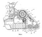
- the cleaning apparatusincludes a base 1 supported at the rear by wheels 2 on either side thereof and at the front by an endless absorbent belt 3. Pivotally connected to the base 1 is a handle assembly 4 including an elongate shaft 5 extending to a handgrip 6. Adjacent the handgrip 6 is a trigger 7. The handle assembly 4 further includes a washing liquid reservoir 8 and a battery enclosure 9. A conduit 10 leads downward from the enclosure 9 to a nozzle 11 located above the belt 3.
- the base 1includes a housing 12 having a cavity 27 in which a contaminated liquid reservoir 13 is received.
- An elongate housing-mounted wringer roller 14is mounted to the housing 12 above the contaminated liquid reservoir 13, extending transversely and supported by journals at both ends.
- a driven gear 15is rotationally fast with the wringer roller 14 at one end thereof.
- the handle assembly 4includes a handle body 4a connected by an articulated joint 16 at its lower end to the housing 12.
- the joint 16is connected at its proximal end by transversely-aligned pivot 17 to a central part of the housing 12.
- a circular collar 18At the distal end of the joint 16 is a circular collar 18 that engages a ring portion 19 formed on the handle body 4a allowing the handle body 4a to pivot relative thereto about the common axis 20 of the collar 18 and ring 19.
- This axis 20is perpendicular to the transverse axis of the pivot 17 for allowing the base 1 to be steered.
- the cavity 27opens rearwardly between the wheels 2, and the contaminated liquid reservoir 13 is slidably received therein allowing it to be removed for emptying.
- the contaminated liquid reservoir 13includes transparent front and rear walls 13a, 13b, side walls 13c, base wall 13d and top wall 13e.
- a channel 27extends substantially along the width of the top wall 13e and drains, via a central portion 28, to an inlet aperture 29 leading into the reservoir 13.
- An elongate resilient wiper 30is mounted to the reservoir 13 and engages the length of the wringer roller 14.
- the contaminated liquid reservoir 13further includes an electrical coupling 31 connected to a liquid level sensor (not shown) for actuating a level warning indicator lamp 65 mounted to the top of the housing 12.
- a closure 32closes an outlet for emptying the reservoir.
- a cleaning head 21is releasably mounted to the front of the housing 12 and incl,udes three elongate and substantially parallel cylindrical head-mounted rollers comprising: drive roller 22, front roller 23 and rear roller 24.
- the head-mounted rollers 22-24are supported for rotation at opposing ends in journals (not shown) fixed in the opposing end plates 25a, 25b which are joined by member 26.
- the drive roller 22encloses a rotary electric motor 33 drivingly connected to a reduction gearbox 34 and to a torque rod 35 which is in turn fixed to the end plate 25b of the head 21 to prevent rotation of the motor and gear box 34.
- Opposing ends of the drive roller 22are supported in bearings 36a, 36b.
- a gearbox output shaft 37is rotationally fast with the driven roller 22 and with a drive gear 38, which in use engages the driven gear 15 for synchronising the peripheral speeds of the driven head roller 22 and the wringer roller 14.
- Electrical coupling parts 41 a and 41 bare fixed to the end plate 25b of cleaning head 21 and housing 12 respectively for supplying power to the motor 33, when the head 21 is connected.
- a guide channel 39 in a central part of the driven roller 22extends circumferentially below its substantially cylindrical outer surface and receives a rib 41 which extends continuously around an inner face of the belt 3.
- Both front roller 23 and rear roller 24also have respective guide channels 42, 43 aligned with the guide channel 39 for cooperating with the circumferential rib 41 to retain the belt 3 in its correct transverse position in use.
- a lower run 44 of the belt 3is supported between the front roller 23 and rear roller 24 at the front of the apparatus and provides the primary area for contacting the surface to be cleaned.
- An exposed upper run 45 of the belt 3extends acutely to the lower run 44 and is supported between the drive roller 22 and front roller 23.
- each of the end plates 25a, 25bFixed on each of the end plates 25a, 25b are nubs 46 which are received in respective recesses 47 in the housing 12 and which cooperate with a manually releasable connector 48 on the head 21 for fastening the head 21 to the housing 12.
- the connector 48includes a lever 49 pivotally mounted to the end plate 25b and having a tongue (not shown) and spring (not shown) which biases the lever 49 such that the tongue is received in the aperture 50 in the housing 12.
- a cooperating lock member(not shown) is mounted to the opposing end plate 25a, and has a respective tongue biased to engage in the opposing aperture 51.
- a rod (not shown)extends between the lever 49 and lock member for releasing both connectors simultaneously.
- the belt 3may be changed when worn, or to provide a belt for a particular operation such as coarse scrubbing, fine polishing or absorbing liquid.
- the belt 3is inserted over the cleaning head 21 with the channels 39, 42, 43 receiving the circumferential rib 41.
- the head 21 and belt 3are then connected to the housing 12 by the cooperating nubs 46 and recesses 47, and the connector 48.
- this operating positionshown in Figs. 1 and 4
- the belt 3is pinched between the wringer roller 14 and the drive roller 22 to squeeze liquid and contaminants from the belt 3 into the reservoir 13. This pinching action also provides good traction for rotating the belt.
- the wringer roller 14deflects the belt 3 inwardly from the line 52 tangential to the adjacent drive roller 22 and rear roller 24 to tension the belt 3, thereby avoiding the need for a separate tensioning device.
- the washing liquid reservoir 8is demountable from the handle assembly 4 and includes a closure 55 at its upper end and a self-closing reservoir valve 56 at its lower end, allowing the reservoir 8 to be removed for filling with water and/or detergent.
- the reservoir valve 56is opened by a stem 57 which communicates with a flexible and resilient tube 58 which extends down behind the batteries 59 and through the conduit 10 to the nozzle 11.
- the liquid flow from the nozzle 11is controlled by a valve 60 operated through a rod 61 connected to the trigger 7.
- the valve 60includes a pinch block 66 abutting the outer wall of the tube 58 fixed to a mount 67 that is connected by a pivot 68 to the inner wall of the enclosure 9.
- a tension spring 69 connected between the mount 67 and the enclosure 9tends to rotate the mount 67 to close the valve, pinching the tube 58 between the block 66 and the fixture 71.
- the valve 60is held open by a slider 70 which engages the mount 67.
- the slider 70is connected to one end of the rod 61.
- the pivotally-mounted trigger 7is connected via a rocker 62 to the rod 61, allowing the trigger 7 to be pulled to open the valve 60.
- the handgrip 6further includes a switch 63 for controlling operation of the motor 33.
- the triggeris operated with the handle assembly 4 upright as shown in Fig. 2 to apply a spray evenly across the width of the upper run 45.
- the cleaning liquidmay be applied preferentially to one or other side of the belt 3.
- the handle assemblyis inclined from the upright and in this position operating the trigger directs a spray onto the surface to be cleaned, as desired.
Landscapes
- Cleaning By Liquid Or Steam (AREA)
Description
- The present invention relates to cleaning apparatus and, more particularly, to apparatus having a motor-driven endless belt able to remove fluids and other contaminants from a surface to be cleaned, such as a floor.
- A typical mop includes a head attached to the end of a handle together with a squeezing mechanism that is used in conjunction with a water bucket to assist in squeezing dirty water out of the mop head. The problem with this prior art cleaning technology and method is that the mop head is rinsed in dirty water, requiring the water in the bucket to be changed frequently and thus making inefficient use of both water and detergent. In addition, prior art systems often leave the cleaned surface wet for a period of time which is longer than desired.
- Cleaning apparatus that address these problems may incorporate the use of electric motors to power components such as rotating cleaning members (for instance brushes or pads) which are trailed by vacuum suction devices that provide means for picking up dirty water which has been produced by the rotating brushes scrubbing up dirt with the water provided by the machine. To achieve reasonable versatility from such machines, it is desirable the cleaning members can be interchanged readily, depending for example upon whether it is desired to use the machine for scrubbing, polishing or drying a surface.
US Patent No. 3 945 078 describes a machine with an open bottom from which a lower run of an endless fabric belt projects downwardly, this belt passing around a large drive roller and several idler rollers. One of the idler rollers is spring-loaded for tensioning the belt and mounted in a reservoir for water or other liquid into which the upper run of the belt dips before passing through a wringer constituted by a further roller pair. The drive roller is hollow and driven by a motor supported in its interior by an axle traversing one of the end faces of that roller. Drawbacks of this machine include the difficulty in replacing the belt, and in particular the necessity to release the spring-loaded tensioning roller when replacing the belt. A large number of rollers are required, increasing manufacturing costs. Furthermore, the dirty liquid wrung from the belt back drains into the reservoir of rinsing water, and due to the lower run of the belt supporting the machine, the machine must be inverted to examine the condition of the belt.US2006010626 describes a floor cleaning apparatus with a cleaning head to which parallel rollers mounted, including a motor-driven roller. An endless cleaning belt is disposed about the rollers of the cleaning head, and pinched between the driven roller and independently mounted spring-biased pinch roller. However, to release the belt for replacement it is necessary both to disengage the spring-biased pinch roller, and to operate a hinge mechanism on the cleaning head. It is an object of the present invention to overcome or substantially ameliorate the above disadvantages or more generally to provide an improved cleaning apparatus.- According to one aspect of the present invention there is provided a cleaning apparatus for cleaning a surface as set forth in
claim 1. - It will be understood that the belt may be pinched between more than one housing-mounted roller and head-mounted roller pair. Also, the belt may be pinched at two or more angular positions on a housing-mounted roller by respective head-mounted rollers, or vice versa at two or more angular positions on a head-mounted roller by respective housing-mounted rollers.
- Preferably each of the head-mounted rollers engages an inner face of the belt. Optionally at least one head-mounted roller may engage an outer face of the belt.
- The drive means preferably comprises a rotary motor mounted to the cleaning head for rotating the driven head-mounted roller. Alternatively the drive means may include a surface-engaging wheel rotated by movement of the apparatus. In the operating position the belt is preferably squeezed between the housing-mounted roller and the driven head-mounted roller. Preferably the rotary motor is mounted within the driven head-mounted roller.
- The housing and the cleaning head preferably further include electrical couplings connected in the operating position to supply power to the motor and separated in the released position.
- Preferably the operating position the housing-mounted roller deflects the belt from a line tangentially connecting the periphery of two adjacent head-mounted rollers to tension the belt. Each of the head-mounted rollers preferably engages an inner face of the belt.
- Preferably the cleaning head is demountably coupled to the housing by cooperating manually releasable connectors on the cleaning head and housing, allowing the cleaning head to be separated from the housing without the use of tools for the removal or replacement of the belt. Optionally, an element such as a hinge may connect the cleaning head and housing in a manner allowing sufficient relative movement from the operating position for removal or fitting of the belt.
- The apparatus preferably further includes synchronising means for synchronising the peripheral speeds the housing-mounted roller and one of the head-mounted rollers between which the belt is squeezed in the operating position.
- Preferably the synchronising means comprises a meshed gear pair, each gear rotationally fast with a respective one of the rollers.
- Preferably the apparatus further includes at least one wheel fixed to the housing for supporting the apparatus upon the surface, the head-mounted rollers include first and second head-mounted rollers, with a lower run of the belt for engaging the surface supported therebetween.
- Preferably the cleaning head is mounted to and projects from a forward end of the housing, an upper run of the belt extends acutely to the lower run and is supported between the drive roller and a forwardmost one of the first and second head-mounted rollers.
- The apparatus preferably further includes a second reservoir, a nozzle for receiving liquid from the second reservoir and spraying the liquid over the upper run and flow control means for controlling the flow of liquid to the nozzle. The flow control means may be a valve or a pump.
- The apparatus preferably further includes a handle connected to the housing to pivot about a first axis generally parallel to roller axes, and about a second axis generally perpendicular to the first axis for allowing the apparatus to be steered. The second reservoir, nozzle and flow control means are preferably fixed to the handle.
- Switch means are preferably mounted on the end of the handle for operating the motor and the flow control means. Preferably a trigger is provided for operating the flow control means and a switch for operating the motor. Optionally, the trigger may have a two-stage operation such that initial depression of the trigger operates the motor and further depression of the trigger operates the flow control means.
- In an alternative embodiment it will be understood that the belt may be tensioned by cooperation between more than one housing-mounted roller and the two adjacent head-mounted rollers. This alternative embodiment may be used, for example, for polishing a.floor
- Preferred forms of the present invention will now be described by way of example with reference to the accompanying drawings, wherein:
Figure 1 is a pictorial view of an embodiment of the surface cleaning apparatus of the invention;Figure 2 is a pictorial view of the apparatus ofFig. 1 disassembled;Figure 3 is a cross section on a plane intersecting a central axis of the driven roller of the apparatus ofFig. 1 ;Figure 4 is a cross section on an upright central plane of the base of the apparatus ofFig. 1 ;Figure 5 is a cross section on an upright central plane of the handle assembly of the apparatus ofFig. 1 ;Figure 6 is a cross section on an upright central plane of the handgrip of the apparatus ofFig. 1 ;- A preferred embodiment of the invention for cleaning floors is illustrated in the drawings, but it will be appreciated that it may be used for cleaning other surfaces such as walls or ceilings with appropriate modification. Referring to
Fig. 1 , the cleaning apparatus includes abase 1 supported at the rear by wheels 2 on either side thereof and at the front by an endlessabsorbent belt 3. Pivotally connected to thebase 1 is ahandle assembly 4 including an elongate shaft 5 extending to a handgrip 6. Adjacent the handgrip 6 is atrigger 7. Thehandle assembly 4 further includes a washingliquid reservoir 8 and a battery enclosure 9. Aconduit 10 leads downward from the enclosure 9 to a nozzle 11 located above thebelt 3. - As seen in
Figs 2 to 4 , thebase 1 includes ahousing 12 having acavity 27 in which a contaminatedliquid reservoir 13 is received. An elongate housing-mountedwringer roller 14 is mounted to thehousing 12 above the contaminatedliquid reservoir 13, extending transversely and supported by journals at both ends. A driven gear 15 is rotationally fast with thewringer roller 14 at one end thereof. - The
handle assembly 4 includes a handle body 4a connected by an articulatedjoint 16 at its lower end to thehousing 12. The joint 16 is connected at its proximal end by transversely-alignedpivot 17 to a central part of thehousing 12. At the distal end of the joint 16 is a circular collar 18 that engages a ring portion 19 formed on the handle body 4a allowing the handle body 4a to pivot relative thereto about thecommon axis 20 of the collar 18 and ring 19. Thisaxis 20 is perpendicular to the transverse axis of thepivot 17 for allowing thebase 1 to be steered. - The
cavity 27 opens rearwardly between the wheels 2, and the contaminatedliquid reservoir 13 is slidably received therein allowing it to be removed for emptying. The contaminatedliquid reservoir 13 includes transparent front andrear walls 13a, 13b, side walls 13c,base wall 13d andtop wall 13e. Achannel 27 extends substantially along the width of thetop wall 13e and drains, via acentral portion 28, to aninlet aperture 29 leading into thereservoir 13. An elongateresilient wiper 30 is mounted to thereservoir 13 and engages the length of thewringer roller 14. The contaminatedliquid reservoir 13 further includes anelectrical coupling 31 connected to a liquid level sensor (not shown) for actuating a levelwarning indicator lamp 65 mounted to the top of thehousing 12. A closure 32 closes an outlet for emptying the reservoir. - A cleaning
head 21 is releasably mounted to the front of thehousing 12 and incl,udes three elongate and substantially parallel cylindrical head-mounted rollers comprising: driveroller 22,front roller 23 and rear roller 24. The head-mounted rollers 22-24 are supported for rotation at opposing ends in journals (not shown) fixed in theopposing end plates 25a, 25b which are joined bymember 26. - The
drive roller 22 encloses a rotaryelectric motor 33 drivingly connected to areduction gearbox 34 and to atorque rod 35 which is in turn fixed to theend plate 25b of thehead 21 to prevent rotation of the motor andgear box 34. Opposing ends of thedrive roller 22 are supported inbearings 36a, 36b. Agearbox output shaft 37 is rotationally fast with the drivenroller 22 and with adrive gear 38, which in use engages the driven gear 15 for synchronising the peripheral speeds of the drivenhead roller 22 and thewringer roller 14. Electrical coupling parts 41 a and 41 b are fixed to theend plate 25b of cleaninghead 21 andhousing 12 respectively for supplying power to themotor 33, when thehead 21 is connected. Aguide channel 39 in a central part of the drivenroller 22 extends circumferentially below its substantially cylindrical outer surface and receives arib 41 which extends continuously around an inner face of thebelt 3. - Both
front roller 23 and rear roller 24 also haverespective guide channels guide channel 39 for cooperating with thecircumferential rib 41 to retain thebelt 3 in its correct transverse position in use. Alower run 44 of thebelt 3 is supported between thefront roller 23 and rear roller 24 at the front of the apparatus and provides the primary area for contacting the surface to be cleaned. An exposedupper run 45 of thebelt 3 extends acutely to thelower run 44 and is supported between thedrive roller 22 andfront roller 23. - Fixed on each of the
end plates 25a, 25b arenubs 46 which are received in respective recesses 47 in thehousing 12 and which cooperate with a manuallyreleasable connector 48 on thehead 21 for fastening thehead 21 to thehousing 12. Theconnector 48 includes alever 49 pivotally mounted to theend plate 25b and having a tongue (not shown) and spring (not shown) which biases thelever 49 such that the tongue is received in the aperture 50 in thehousing 12. A cooperating lock member (not shown) is mounted to the opposing end plate 25a, and has a respective tongue biased to engage in the opposingaperture 51. A rod (not shown) extends between thelever 49 and lock member for releasing both connectors simultaneously. - In use the
belt 3 may be changed when worn, or to provide a belt for a particular operation such as coarse scrubbing, fine polishing or absorbing liquid. Thebelt 3 is inserted over the cleaninghead 21 with thechannels circumferential rib 41. Thehead 21 andbelt 3 are then connected to thehousing 12 by the cooperatingnubs 46 and recesses 47, and theconnector 48. In this operating position (shown inFigs. 1 and4 ) thebelt 3 is pinched between thewringer roller 14 and thedrive roller 22 to squeeze liquid and contaminants from thebelt 3 into thereservoir 13. This pinching action also provides good traction for rotating the belt. Thewringer roller 14 deflects thebelt 3 inwardly from theline 52 tangential to theadjacent drive roller 22 and rear roller 24 to tension thebelt 3, thereby avoiding the need for a separate tensioning device. - Referring to
Figs. 5 and 6 thewashing liquid reservoir 8 is demountable from thehandle assembly 4 and includes aclosure 55 at its upper end and a self-closingreservoir valve 56 at its lower end, allowing thereservoir 8 to be removed for filling with water and/or detergent. Thereservoir valve 56 is opened by astem 57 which communicates with a flexible andresilient tube 58 which extends down behind thebatteries 59 and through theconduit 10 to the nozzle 11. The liquid flow from the nozzle 11 is controlled by avalve 60 operated through arod 61 connected to thetrigger 7. Thevalve 60 includes apinch block 66 abutting the outer wall of thetube 58 fixed to amount 67 that is connected by apivot 68 to the inner wall of the enclosure 9. Atension spring 69 connected between themount 67 and the enclosure 9 tends to rotate themount 67 to close the valve, pinching thetube 58 between theblock 66 and thefixture 71. Thevalve 60 is held open by a slider 70 which engages themount 67. The slider 70 is connected to one end of therod 61. The pivotally-mountedtrigger 7 is connected via a rocker 62 to therod 61, allowing thetrigger 7 to be pulled to open thevalve 60. The handgrip 6 further includes aswitch 63 for controlling operation of themotor 33. - In use the trigger is operated with the
handle assembly 4 upright as shown inFig. 2 to apply a spray evenly across the width of theupper run 45. Optionally, by rotating thehandle assembly 4 about theaxis 20 with the handle assembly upright the cleaning liquid may be applied preferentially to one or other side of thebelt 3. In use, the handle assembly is inclined from the upright and in this position operating the trigger directs a spray onto the surface to be cleaned, as desired. - Aspects of the present invention have been described by way of example only and it should be appreciated that modifications and additions may be made thereto without departing from the scope thereof.
Claims (14)
- A cleaning apparatus for cleaning a surface, comprising:a housing (12);a housing-mounted roller (14) mounted to the housing;a cleaning head (21) releasably coupled to the housing;a plurality of head-mounted rollers (22, 23, 24) mounted on the cleaning head;drive means (33, 34, 35) operatively connected to at least a driven one of the head-mounted rollers (22) for rotation of the driven head-mounted roller (22), andan endless belt (3) supported for rotation about the head-mounted rollers, the belt being pinched between the housing-mounted roller (14) and driven head-mounted roller (22),characterised in that, in an operating position, the housing-mounted roller (14) deflects the belt from a line tangential to the driven head-mounted roller (22) and an adjacent one of the head-mounted rollers to tension the belt, and the cleaning head is movable relative to the housing from the operating position to a released position in which the belt tension is released to remove the belt.
- A cleaning apparatus of claim 1 wherein
the housing (12) holds a first reservoir (13);
the endless belt (3) is absorbent and the belt is pinched between the housing-mounted roller (14) and the driven head-mounted roller to squeeze liquid and contaminants from the belt into the first reservoir. - The apparatus of claim 1 or claim 2 wherein the drive means (33, 34, 35) comprises a rotary motor (33) mounted to the cleaning head for rotating the driven head-mounted roller.
- The apparatus of claim 3 wherein the rotary motor is mounted within the driven head-mounted roller.
- The apparatus of claim 3 or claim 4 wherein the housing and the cleaning head further include electrical couplings that are connected in the operating position to supply power to the rotary motor (33) and that are separated in the released position.
- The apparatus of any one of claims 1 to 5 wherein each of the head-mounted rollers engages an inner face of the belt.
- The apparatus of any one of claims 1 to 6 wherein the cleaning head is demountably coupled to the housing by cooperating manually releasable connectors on the cleaning head and housing.
- The apparatus of any one of claims 1 to 7 further including synchronising means (15, 38) for synchronising the peripheral speeds the housing-mounted roller and the driven head-mounted roller between which the belt is squeezed in the operating position.
- The apparatus of claim 8 wherein the synchronising means comprises a meshed gear pair (15, 38), each gear rotationally fast with a respective one of the housing-mounted roller and the driven head-mounted roller.
- The apparatus of any one of claims 1 to 9 further including at least one wheel (2) fixed to the housing for supporting the apparatus upon the surface, wherein the head-mounted rollers include first and second head-mounted rollers (23, 24), with a lower run (44) of the belt for engaging the surface supported therebetween.
- The apparatus of claim 10 wherein the cleaning head is mounted to and projects from a forward end of the housing, an upper run (45) of the belt extends acutely to the lower run and is supported between the drive roller and a forwardmost one (23) of the first and second head-mounted rollers.
- The apparatus of any one of claims 1 to 11 further including a second reservoir (9), a nozzle (11) for receiving liquid from the second reservoir and spraying the liquid over the belt (3) and flow control means (60) for controlling the flow of liquid to the nozzle.
- The apparatus of claim 12 further including a handle (4) connected to the housing to pivot about a first axis generally parallel to roller axes, and about a second axis generally perpendicular to the first axis for allowing the apparatus to be steered, preferably wherein the second reservoir, nozzle and flow control means are fixed to the handle.
- The apparatus of any one of claims 1 to 13 wherein for locating the belt transversely on the rollers the belt includes a rib or groove on an inner face thereof and at least one of the rollers has a complementary groove or rib respectively for engagement therewith.
Applications Claiming Priority (2)
| Application Number | Priority Date | Filing Date | Title |
|---|---|---|---|
| US11/753,816US7950105B2 (en) | 2007-05-25 | 2007-05-25 | Cleaning apparatus with motorised endless belt |
| PCT/IB2008/052053WO2008146227A1 (en) | 2007-05-25 | 2008-05-26 | Cleaning apparatus with motor-driven endless belt |
Publications (2)
| Publication Number | Publication Date |
|---|---|
| EP2166913A1 EP2166913A1 (en) | 2010-03-31 |
| EP2166913B1true EP2166913B1 (en) | 2013-06-26 |
Family
ID=39791782
Family Applications (1)
| Application Number | Title | Priority Date | Filing Date |
|---|---|---|---|
| EP08763102.4AActiveEP2166913B1 (en) | 2007-05-25 | 2008-05-26 | Cleaning apparatus with motor-driven endless belt |
Country Status (4)
| Country | Link |
|---|---|
| US (1) | US7950105B2 (en) |
| EP (1) | EP2166913B1 (en) |
| CN (1) | CN101677738B (en) |
| WO (1) | WO2008146227A1 (en) |
Families Citing this family (12)
| Publication number | Priority date | Publication date | Assignee | Title |
|---|---|---|---|---|
| US8756757B2 (en)* | 2011-09-07 | 2014-06-24 | Bissell Homecare, Inc. | Vacuum cleaner with belt drive disengager |
| US9248974B2 (en) | 2013-03-08 | 2016-02-02 | Mark S. Grill | Cleaning apparatus, methods of making cleaning apparatus, and methods of cleaning |
| WO2016053221A1 (en)* | 2014-09-29 | 2016-04-07 | Yapim Elektrik San. Ve Tic. A.S. | Automatic hard floor cleaning head |
| JP2019014092A (en)* | 2017-07-04 | 2019-01-31 | キヤノン株式会社 | Recording apparatus and recording method |
| GB2570972B (en)* | 2018-02-13 | 2020-07-01 | Hizero Tech Co Ltd | A ground cleaning device |
| CN111449560A (en)* | 2019-01-21 | 2020-07-28 | 科沃斯机器人股份有限公司 | Surface cleaning robot |
| CN113645888B (en)* | 2019-04-08 | 2023-06-20 | 阿尔弗雷德·卡赫欧洲两合公司 | Surface cleaning machine with dirty fluid tank assembly |
| CN110881910A (en)* | 2019-12-05 | 2020-03-17 | 杨洪新 | Domestic novel super clean self-service cleaning machine |
| CN116669607A (en) | 2020-07-29 | 2023-08-29 | 涤朗创意有限公司 | Multifunctional cleaning appliance |
| CN114101130B (en)* | 2021-11-15 | 2022-08-02 | 湖南机电职业技术学院 | An automatic and efficient cleaning device |
| DE102022102937A1 (en) | 2022-02-08 | 2023-08-10 | Alfred Kärcher SE & Co. KG | Floor cleaning device with dirt fluid tank |
| WO2023152163A1 (en) | 2022-02-08 | 2023-08-17 | Alfred Kärcher SE & Co. KG | Floor cleaning device with a pivot bearing unit with an abutment |
Citations (2)
| Publication number | Priority date | Publication date | Assignee | Title |
|---|---|---|---|---|
| US2268073A (en)* | 1940-12-23 | 1941-12-30 | Harold J Hunn | Motor-operated mopping device |
| US20060010626A1 (en)* | 2002-06-13 | 2006-01-19 | Aktiebolaget Electrolux | Portable surface treating apparatus |
Family Cites Families (13)
| Publication number | Priority date | Publication date | Assignee | Title |
|---|---|---|---|---|
| FR1009211A (en) | 1948-05-26 | 1952-05-27 | Mechanical polisher | |
| US2930257A (en)* | 1955-01-26 | 1960-03-29 | Gen Motors Corp | Transmission |
| USRE25419E (en) | 1958-07-09 | 1963-07-23 | evans | |
| US3047894A (en) | 1961-05-16 | 1962-08-07 | George O Sprang | Floor scrubbing machine |
| IT1013584B (en)* | 1973-10-16 | 1977-03-30 | Acquaro M | COMPLETELY AUTOMATIC MACHINE FOR WASHING, DRYING AND CLEANING FLOORS CHARACTERIZED BY HAVING A TRAVELING CARPET WITH A CONTINUALLY CLOSED CYCLE SLIPPING THE SURFACE TO BE WORKED SOAKED WITH WATER OR TABLETED IN THE CORRESPONDING WASHING AND DRYING OPERATIONS |
| DE3519742A1 (en) | 1985-06-01 | 1987-01-02 | Monika Marchand | Device for scrubbing and mopping |
| US4926515A (en)* | 1987-03-03 | 1990-05-22 | Lynn William R | Improved mopping system |
| CA2279873C (en) | 1997-02-28 | 2004-12-21 | E.I. Du Pont De Nemours And Company | Apparatus having a belt agitator for agitating a cleaning agent into a carpet |
| US5933900A (en)* | 1997-05-28 | 1999-08-10 | Wang; Xiao Chun | Modular floor cleaning machine |
| DE10020197B4 (en) | 2000-04-25 | 2004-01-22 | Dieter Prof. Dr.-Ing. Tremmel | Floor cleaning device |
| US20040172769A1 (en)* | 2001-06-20 | 2004-09-09 | Giddings Daniel G. | Method and apparatus for cleaning fabrics, floor coverings, and bare floor surfaces utilizing a soil transfer cleaning medium |
| FR2836363A1 (en) | 2002-02-22 | 2003-08-29 | Diamant Boart Sa | Machine for cleaning ceramic floor tiles after grouting has wet, sloping, absorbent endless belt which contacts floor at its lower end and then passes through narrow gap between transverse bar and upper plate |
| CN2894588Y (en)* | 2006-06-05 | 2007-05-02 | 朱凌锋 | Floor cleaning machine |
- 2007
- 2007-05-25USUS11/753,816patent/US7950105B2/enactiveActive
- 2008
- 2008-05-26EPEP08763102.4Apatent/EP2166913B1/enactiveActive
- 2008-05-26CNCN2008800173075Apatent/CN101677738B/enactiveActive
- 2008-05-26WOPCT/IB2008/052053patent/WO2008146227A1/enactiveApplication Filing
Patent Citations (2)
| Publication number | Priority date | Publication date | Assignee | Title |
|---|---|---|---|---|
| US2268073A (en)* | 1940-12-23 | 1941-12-30 | Harold J Hunn | Motor-operated mopping device |
| US20060010626A1 (en)* | 2002-06-13 | 2006-01-19 | Aktiebolaget Electrolux | Portable surface treating apparatus |
Also Published As
| Publication number | Publication date |
|---|---|
| US20080289142A1 (en) | 2008-11-27 |
| US7950105B2 (en) | 2011-05-31 |
| WO2008146227A1 (en) | 2008-12-04 |
| CN101677738B (en) | 2012-03-28 |
| CN101677738A (en) | 2010-03-24 |
| EP2166913A1 (en) | 2010-03-31 |
Similar Documents
| Publication | Publication Date | Title |
|---|---|---|
| EP2166913B1 (en) | Cleaning apparatus with motor-driven endless belt | |
| US20230157504A1 (en) | Cleaning device | |
| AU2021201370B2 (en) | Surface cleaning apparatus and tray | |
| US5657504A (en) | Roller mop with wet roller, squeegee, and debris pickup | |
| US10881258B2 (en) | Surface cleaning machine and method for operating a surface cleaning machine | |
| US11253126B2 (en) | Robot cleaner | |
| US7159275B2 (en) | Glass surface cleaning machine | |
| GB2251180A (en) | Vacuum cleaner with wiping action | |
| CN213640755U (en) | Roller type floor cleaner | |
| CN101712035B (en) | Wet cleaner | |
| EP4307976B1 (en) | Supplying liquid to at least one wheel of a suction head | |
| EP2498661B1 (en) | Integrated vacuum wand and method of use | |
| US20030009843A1 (en) | Automate glass surface cleaning machine | |
| KR102019107B1 (en) | Cleaner | |
| JP2021104341A (en) | Surface cleaning apparatus and tray | |
| KR20240016942A (en) | Supply of liquid to at least one area of the surface to be cleaned | |
| CN115886649A (en) | Cleaning head with multiple cleaners | |
| KR960007470B1 (en) | Manual mop cleaner | |
| JP7753117B2 (en) | Articulated vacuum cleaner | |
| CN217090619U (en) | Surface cleaning equipment and cleaning head thereof | |
| CN222885348U (en) | Scraping bar assembly, floor brush and wet surface cleaner | |
| CN216728434U (en) | Portable cleaning device of gluing machine | |
| CN215016865U (en) | Floor wiping system | |
| JP2023107589A (en) | Connection type vacuum cleaner | |
| CN120713424A (en) | High-efficient clean formula floor washing machine |
Legal Events
| Date | Code | Title | Description |
|---|---|---|---|
| PUAI | Public reference made under article 153(3) epc to a published international application that has entered the european phase | Free format text:ORIGINAL CODE: 0009012 | |
| 17P | Request for examination filed | Effective date:20091222 | |
| AK | Designated contracting states | Kind code of ref document:A1 Designated state(s):AT BE BG CH CY CZ DE DK EE ES FI FR GB GR HR HU IE IS IT LI LT LU LV MC MT NL NO PL PT RO SE SI SK TR | |
| AX | Request for extension of the european patent | Extension state:AL BA MK RS | |
| DAX | Request for extension of the european patent (deleted) | ||
| 17Q | First examination report despatched | Effective date:20101209 | |
| GRAP | Despatch of communication of intention to grant a patent | Free format text:ORIGINAL CODE: EPIDOSNIGR1 | |
| GRAS | Grant fee paid | Free format text:ORIGINAL CODE: EPIDOSNIGR3 | |
| GRAA | (expected) grant | Free format text:ORIGINAL CODE: 0009210 | |
| AK | Designated contracting states | Kind code of ref document:B1 Designated state(s):AT BE BG CH CY CZ DE DK EE ES FI FR GB GR HR HU IE IS IT LI LT LU LV MC MT NL NO PL PT RO SE SI SK TR | |
| REG | Reference to a national code | Ref country code:GB Ref legal event code:FG4D | |
| REG | Reference to a national code | Ref country code:CH Ref legal event code:EP | |
| REG | Reference to a national code | Ref country code:AT Ref legal event code:REF Ref document number:618312 Country of ref document:AT Kind code of ref document:T Effective date:20130715 | |
| RAP2 | Party data changed (patent owner data changed or rights of a patent transferred) | Owner name:C ENTERPRISE (HK) LIMITED | |
| REG | Reference to a national code | Ref country code:IE Ref legal event code:FG4D | |
| REG | Reference to a national code | Ref country code:DE Ref legal event code:R096 Ref document number:602008025589 Country of ref document:DE Effective date:20130822 | |
| PG25 | Lapsed in a contracting state [announced via postgrant information from national office to epo] | Ref country code:SE Free format text:LAPSE BECAUSE OF FAILURE TO SUBMIT A TRANSLATION OF THE DESCRIPTION OR TO PAY THE FEE WITHIN THE PRESCRIBED TIME-LIMIT Effective date:20130626 Ref country code:SI Free format text:LAPSE BECAUSE OF FAILURE TO SUBMIT A TRANSLATION OF THE DESCRIPTION OR TO PAY THE FEE WITHIN THE PRESCRIBED TIME-LIMIT Effective date:20130626 Ref country code:GR Free format text:LAPSE BECAUSE OF FAILURE TO SUBMIT A TRANSLATION OF THE DESCRIPTION OR TO PAY THE FEE WITHIN THE PRESCRIBED TIME-LIMIT Effective date:20130927 Ref country code:NO Free format text:LAPSE BECAUSE OF FAILURE TO SUBMIT A TRANSLATION OF THE DESCRIPTION OR TO PAY THE FEE WITHIN THE PRESCRIBED TIME-LIMIT Effective date:20130926 Ref country code:LT Free format text:LAPSE BECAUSE OF FAILURE TO SUBMIT A TRANSLATION OF THE DESCRIPTION OR TO PAY THE FEE WITHIN THE PRESCRIBED TIME-LIMIT Effective date:20130626 Ref country code:FI Free format text:LAPSE BECAUSE OF FAILURE TO SUBMIT A TRANSLATION OF THE DESCRIPTION OR TO PAY THE FEE WITHIN THE PRESCRIBED TIME-LIMIT Effective date:20130626 | |
| REG | Reference to a national code | Ref country code:AT Ref legal event code:MK05 Ref document number:618312 Country of ref document:AT Kind code of ref document:T Effective date:20130626 | |
| REG | Reference to a national code | Ref country code:LT Ref legal event code:MG4D | |
| PG25 | Lapsed in a contracting state [announced via postgrant information from national office to epo] | Ref country code:HR Free format text:LAPSE BECAUSE OF FAILURE TO SUBMIT A TRANSLATION OF THE DESCRIPTION OR TO PAY THE FEE WITHIN THE PRESCRIBED TIME-LIMIT Effective date:20130626 Ref country code:BG Free format text:LAPSE BECAUSE OF FAILURE TO SUBMIT A TRANSLATION OF THE DESCRIPTION OR TO PAY THE FEE WITHIN THE PRESCRIBED TIME-LIMIT Effective date:20130926 | |
| REG | Reference to a national code | Ref country code:NL Ref legal event code:VDEP Effective date:20130626 | |
| PG25 | Lapsed in a contracting state [announced via postgrant information from national office to epo] | Ref country code:LV Free format text:LAPSE BECAUSE OF FAILURE TO SUBMIT A TRANSLATION OF THE DESCRIPTION OR TO PAY THE FEE WITHIN THE PRESCRIBED TIME-LIMIT Effective date:20130626 | |
| PG25 | Lapsed in a contracting state [announced via postgrant information from national office to epo] | Ref country code:EE Free format text:LAPSE BECAUSE OF FAILURE TO SUBMIT A TRANSLATION OF THE DESCRIPTION OR TO PAY THE FEE WITHIN THE PRESCRIBED TIME-LIMIT Effective date:20130626 Ref country code:PT Free format text:LAPSE BECAUSE OF FAILURE TO SUBMIT A TRANSLATION OF THE DESCRIPTION OR TO PAY THE FEE WITHIN THE PRESCRIBED TIME-LIMIT Effective date:20131028 Ref country code:SK Free format text:LAPSE BECAUSE OF FAILURE TO SUBMIT A TRANSLATION OF THE DESCRIPTION OR TO PAY THE FEE WITHIN THE PRESCRIBED TIME-LIMIT Effective date:20130626 Ref country code:BE Free format text:LAPSE BECAUSE OF FAILURE TO SUBMIT A TRANSLATION OF THE DESCRIPTION OR TO PAY THE FEE WITHIN THE PRESCRIBED TIME-LIMIT Effective date:20130626 Ref country code:AT Free format text:LAPSE BECAUSE OF FAILURE TO SUBMIT A TRANSLATION OF THE DESCRIPTION OR TO PAY THE FEE WITHIN THE PRESCRIBED TIME-LIMIT Effective date:20130626 Ref country code:IS Free format text:LAPSE BECAUSE OF FAILURE TO SUBMIT A TRANSLATION OF THE DESCRIPTION OR TO PAY THE FEE WITHIN THE PRESCRIBED TIME-LIMIT Effective date:20131026 Ref country code:CY Free format text:LAPSE BECAUSE OF FAILURE TO SUBMIT A TRANSLATION OF THE DESCRIPTION OR TO PAY THE FEE WITHIN THE PRESCRIBED TIME-LIMIT Effective date:20130821 Ref country code:CZ Free format text:LAPSE BECAUSE OF FAILURE TO SUBMIT A TRANSLATION OF THE DESCRIPTION OR TO PAY THE FEE WITHIN THE PRESCRIBED TIME-LIMIT Effective date:20130626 | |
| PG25 | Lapsed in a contracting state [announced via postgrant information from national office to epo] | Ref country code:RO Free format text:LAPSE BECAUSE OF FAILURE TO SUBMIT A TRANSLATION OF THE DESCRIPTION OR TO PAY THE FEE WITHIN THE PRESCRIBED TIME-LIMIT Effective date:20130626 Ref country code:PL Free format text:LAPSE BECAUSE OF FAILURE TO SUBMIT A TRANSLATION OF THE DESCRIPTION OR TO PAY THE FEE WITHIN THE PRESCRIBED TIME-LIMIT Effective date:20130626 Ref country code:ES Free format text:LAPSE BECAUSE OF FAILURE TO SUBMIT A TRANSLATION OF THE DESCRIPTION OR TO PAY THE FEE WITHIN THE PRESCRIBED TIME-LIMIT Effective date:20131007 Ref country code:NL Free format text:LAPSE BECAUSE OF FAILURE TO SUBMIT A TRANSLATION OF THE DESCRIPTION OR TO PAY THE FEE WITHIN THE PRESCRIBED TIME-LIMIT Effective date:20130626 | |
| PG25 | Lapsed in a contracting state [announced via postgrant information from national office to epo] | Ref country code:CY Free format text:LAPSE BECAUSE OF FAILURE TO SUBMIT A TRANSLATION OF THE DESCRIPTION OR TO PAY THE FEE WITHIN THE PRESCRIBED TIME-LIMIT Effective date:20130626 | |
| PG25 | Lapsed in a contracting state [announced via postgrant information from national office to epo] | Ref country code:DK Free format text:LAPSE BECAUSE OF FAILURE TO SUBMIT A TRANSLATION OF THE DESCRIPTION OR TO PAY THE FEE WITHIN THE PRESCRIBED TIME-LIMIT Effective date:20130626 | |
| PLBE | No opposition filed within time limit | Free format text:ORIGINAL CODE: 0009261 | |
| STAA | Information on the status of an ep patent application or granted ep patent | Free format text:STATUS: NO OPPOSITION FILED WITHIN TIME LIMIT | |
| PG25 | Lapsed in a contracting state [announced via postgrant information from national office to epo] | Ref country code:IT Free format text:LAPSE BECAUSE OF FAILURE TO SUBMIT A TRANSLATION OF THE DESCRIPTION OR TO PAY THE FEE WITHIN THE PRESCRIBED TIME-LIMIT Effective date:20130626 | |
| 26N | No opposition filed | Effective date:20140327 | |
| REG | Reference to a national code | Ref country code:DE Ref legal event code:R097 Ref document number:602008025589 Country of ref document:DE Effective date:20140327 | |
| PG25 | Lapsed in a contracting state [announced via postgrant information from national office to epo] | Ref country code:LU Free format text:LAPSE BECAUSE OF FAILURE TO SUBMIT A TRANSLATION OF THE DESCRIPTION OR TO PAY THE FEE WITHIN THE PRESCRIBED TIME-LIMIT Effective date:20140526 | |
| REG | Reference to a national code | Ref country code:CH Ref legal event code:PL | |
| PG25 | Lapsed in a contracting state [announced via postgrant information from national office to epo] | Ref country code:MC Free format text:LAPSE BECAUSE OF FAILURE TO SUBMIT A TRANSLATION OF THE DESCRIPTION OR TO PAY THE FEE WITHIN THE PRESCRIBED TIME-LIMIT Effective date:20130626 Ref country code:LI Free format text:LAPSE BECAUSE OF NON-PAYMENT OF DUE FEES Effective date:20140531 Ref country code:CH Free format text:LAPSE BECAUSE OF NON-PAYMENT OF DUE FEES Effective date:20140531 | |
| REG | Reference to a national code | Ref country code:IE Ref legal event code:MM4A | |
| REG | Reference to a national code | Ref country code:FR Ref legal event code:ST Effective date:20150130 | |
| PG25 | Lapsed in a contracting state [announced via postgrant information from national office to epo] | Ref country code:IE Free format text:LAPSE BECAUSE OF NON-PAYMENT OF DUE FEES Effective date:20140526 | |
| PG25 | Lapsed in a contracting state [announced via postgrant information from national office to epo] | Ref country code:FR Free format text:LAPSE BECAUSE OF NON-PAYMENT OF DUE FEES Effective date:20140602 | |
| PGFP | Annual fee paid to national office [announced via postgrant information from national office to epo] | Ref country code:DE Payment date:20151127 Year of fee payment:8 | |
| PG25 | Lapsed in a contracting state [announced via postgrant information from national office to epo] | Ref country code:MT Free format text:LAPSE BECAUSE OF FAILURE TO SUBMIT A TRANSLATION OF THE DESCRIPTION OR TO PAY THE FEE WITHIN THE PRESCRIBED TIME-LIMIT Effective date:20130626 | |
| PG25 | Lapsed in a contracting state [announced via postgrant information from national office to epo] | Ref country code:HU Free format text:LAPSE BECAUSE OF FAILURE TO SUBMIT A TRANSLATION OF THE DESCRIPTION OR TO PAY THE FEE WITHIN THE PRESCRIBED TIME-LIMIT; INVALID AB INITIO Effective date:20080526 Ref country code:TR Free format text:LAPSE BECAUSE OF FAILURE TO SUBMIT A TRANSLATION OF THE DESCRIPTION OR TO PAY THE FEE WITHIN THE PRESCRIBED TIME-LIMIT Effective date:20130626 | |
| REG | Reference to a national code | Ref country code:DE Ref legal event code:R119 Ref document number:602008025589 Country of ref document:DE | |
| PG25 | Lapsed in a contracting state [announced via postgrant information from national office to epo] | Ref country code:DE Free format text:LAPSE BECAUSE OF NON-PAYMENT OF DUE FEES Effective date:20161201 | |
| REG | Reference to a national code | Ref country code:GB Ref legal event code:732E Free format text:REGISTERED BETWEEN 20190815 AND 20190821 | |
| REG | Reference to a national code | Ref country code:GB Ref legal event code:732E Free format text:REGISTERED BETWEEN 20210617 AND 20210623 | |
| PGFP | Annual fee paid to national office [announced via postgrant information from national office to epo] | Ref country code:GB Payment date:20240530 Year of fee payment:17 |