EP2166435B1 - Information processing apparatus and information processing method - Google Patents
Information processing apparatus and information processing methodDownload PDFInfo
- Publication number
- EP2166435B1 EP2166435B1EP09251558AEP09251558AEP2166435B1EP 2166435 B1EP2166435 B1EP 2166435B1EP 09251558 AEP09251558 AEP 09251558AEP 09251558 AEP09251558 AEP 09251558AEP 2166435 B1EP2166435 B1EP 2166435B1
- Authority
- EP
- European Patent Office
- Prior art keywords
- proximity
- centroid
- region
- value
- calculation unit
- Prior art date
- Legal status (The legal status is an assumption and is not a legal conclusion. Google has not performed a legal analysis and makes no representation as to the accuracy of the status listed.)
- Not-in-force
Links
Images


Classifications
- G—PHYSICS
- G06—COMPUTING OR CALCULATING; COUNTING
- G06F—ELECTRIC DIGITAL DATA PROCESSING
- G06F3/00—Input arrangements for transferring data to be processed into a form capable of being handled by the computer; Output arrangements for transferring data from processing unit to output unit, e.g. interface arrangements
- G06F3/01—Input arrangements or combined input and output arrangements for interaction between user and computer
- G06F3/03—Arrangements for converting the position or the displacement of a member into a coded form
- G06F3/041—Digitisers, e.g. for touch screens or touch pads, characterised by the transducing means
- G06F3/042—Digitisers, e.g. for touch screens or touch pads, characterised by the transducing means by opto-electronic means
- G—PHYSICS
- G06—COMPUTING OR CALCULATING; COUNTING
- G06F—ELECTRIC DIGITAL DATA PROCESSING
- G06F3/00—Input arrangements for transferring data to be processed into a form capable of being handled by the computer; Output arrangements for transferring data from processing unit to output unit, e.g. interface arrangements
- G06F3/01—Input arrangements or combined input and output arrangements for interaction between user and computer
- G06F3/03—Arrangements for converting the position or the displacement of a member into a coded form
- G06F3/041—Digitisers, e.g. for touch screens or touch pads, characterised by the transducing means
- G06F3/0416—Control or interface arrangements specially adapted for digitisers
- G06F3/0418—Control or interface arrangements specially adapted for digitisers for error correction or compensation, e.g. based on parallax, calibration or alignment
- G06F3/04186—Touch location disambiguation
Definitions
- the present inventionrelates to an information processing apparatus and information processing method.
- a display deviceincludes a touch panel (touch screen) in which an electrostatic capacitance or resistive touch sensor is provided on a surface of a display unit such as liquid crystal display. With the touch panel, the user can touch the screen of the display unit to input information into the information processing apparatus so that the user can easily manipulate the information processing apparatus.
- a touch paneltouch screen
- an electrostatic capacitance or resistive touch sensoris provided on a surface of a display unit such as liquid crystal display.
- a capacitive multi-touch screenis for example disclosed in WO 2005/114369A .
- a touch panel technique other than electrostatic capacitance or resistive typeis disclosed as a display device for detecting an operation near the display unit.
- Japanese Patent Application Laid-Open No. 2006-276223discloses a technique in which a display device simultaneously performs light emission and light reception.
- Japanese Patent Application Laid-Open No. 11-24839discloses a technique for operating a computer device in response to an operation of operator's hand or human body.
- Japanese Patent Application Laid-Open No. 2008-146165discloses a panel technique capable of outputting information on several points with respect to input points on the panel.
- a contact or proximity to a touch panelis detected as a region occupying a certain area on the touch panel.
- the centroid of the contact region or proximity region having a certain areais calculated to determine the calculated centroid position as the representative point of the contact or proximity.
- the point which is determined as being contacted on or proximate to the touch panel based on the centroid of the regionis different from a point which a user intends to contact or be proximate to.
- a different button from a user-intended buttonmay be selected due to how to hold the touch panel or a length of a user's nail.
- the touch panelin consideration of how to hold the touch panel or use's usage, it may be possible to assume user's intention to a certain degree and to calculate a different point from an actually-detected contact point or proximity point as a user-intended point depending on a detection position on the screen.
- the touch panelcan be variously utilized such as vertically, horizontally, upside down. Thus, it was difficult to previously assume how to hold the touch panel or its usage and to correct the contact point or proximity point based on the assumption.
- US 2007/0097096Adiscloses a touch screen interaction method wherein a direct targeting mode and an offset targeting mode is implemented based on the size, shape and orientation of the area where a figures is touching the touch screen.
- US 2007/0300182Adescribes a user interface for a touch screen device where the orientation of the object touching the screen determines the orientation and the position of a displayed user interface element.
- the present inventionhas been made in view of the above issues, and it is desirable to provide a novel and improved information processing apparatus and information processing method capable of correcting a contact position or proximity position not to a detected contact position or proximity position but to a user-intended contact position or proximity position with high accuracy.
- a contact position or proximity positioncan be corrected to be closer not to a detected contact position or proximity position but to a user-intended contact position or proximity position with high accuracy.
- FIG. 1is a block diagram showing the information processing apparatus 100 according to the present embodiment.
- the information processing apparatus 100includes a control unit 102, a memory 104, a storage 106, an input I/F 107, an image signal processing unit 114, a display panel 108, a display control unit 112, a speech output I/F 116, a light reception processing unit 122 and the like, for example.
- a control unit 102controls the display panel 108, but the present invention can be applied to a case in which the information processing apparatus 100 and the display panel 108 are separately provided.
- the information processing apparatus 100is a personal computer, audio player, media player, PDA (personal digital assistant), cell phone, digital camera or the like, for example.
- the control unit 102has a microcomputer which is configured in combination with a CPU (Central Processing Unit), a ROM (Read Only Memory), a RAM (Random Access Memory) and the like.
- the control unit 102functions as a calculation processing device and a control device by programs, and controls the above respective constituents in the information processing apparatus 100.
- a signalis input into the control unit 102 from the touch panel 112 receiving an operation from outside.
- the memory 104is configured with a storage unit such as RAM, ROM or cache memory, and has a function of temporarily storing therein data relating to the processing of the CPU of the control unit 102 or operation programs of the CPU.
- a storage unitsuch as RAM, ROM or cache memory
- the storage 106is, for example, a hard disk, optical disk, flash memory or the like, and is a storage unit for storing therein data for a long time.
- the storage 106stores therein music data or video data such as videos or photographs, for example.
- the storage 106stores therein the music data or the video data through a data reception control processing and accumulation control processing in the control unit 102.
- the input I/F 107is, for example, a USB terminal, IEEE 1394 terminal or the like, and is an interface which is connectable to an external device. Various items of information or instructions are input into the information processing apparatus 100 via the input I/F 107.
- the image signal processing unit 114performs a signal processing on an image signal generated in the light reception processing unit 122.
- the image signal processing unit 114performs various required signal processings such as resolution conversion for converting an image signal into the number of pixels of the display unit 110, luminance correction, color correction and gamma correction.
- the display panel 108includes, for example, the display unit 110, the light reception sensor 120 and the like, and the light reception sensor 120 detects an operation object such as a user's finger or hand to accept the user's operation.
- the display panel 108according to the present embodiment does not need to contact the screen unlike the touch panel, and detects a proximity to the screen to accept the user's operation. Then, the display panel 108 selects an item displayed on the screen, scrolls the screen or changes a zoom-in or zoom-out display in response to the user's operation.
- the display unit 110is a liquid crystal display, for example, and is controlled by the display control unit 112.
- the display unit 110displays various menu screens or images based on image data.
- the light reception sensor 120is one example of a light reception unit, which receives a light incident into the display screen of the display unit 110 from outside to convert the received light into an electric signal.
- the light reception sensor 120sends the generated electric signal to the light reception processing unit 122.
- the speech output I/F 116is, for example, a terminal for a phone plug or the like, and is connected to an external device such as headphone or speaker.
- the speech output I/F 116outputs reproduced speech data to the external device.
- FIG. 2is an explanatory diagram showing pixels of the display panel 108 according to the present embodiment.
- a plurality of pixel sets 130are arranged in the display panel 108 in a matrix manner.
- the pixel set 130is provided with a red display pixel 110R, a green display pixel 110G, a blue display pixel 110B, which are light emitting elements, and a light reception sensor 120.
- the display pixels 110R, 110G, 110B and the light reception sensor 120are adjacently arranged in one pixel set 130.
- the arrangement of pixelsis not limited to the example shown in FIG. 2 and other arrangement may be employed.
- the information processing apparatus 100can detect the operation object.
- the display control unit 112utilizes an input image signal to drive the display unit 110.
- the display control unit 112performs a display processing on the image signal received from the image signal processing unit 114. Further, the display control unit 112 combines the display data and generates user-viewable data in the display unit 110. The data generated in the display control unit 112 is output to the display unit 110.
- the light reception processing unit 122receives the electric signal from the light reception sensor 120 to perform A/D conversion processing or the like, and generates an image signal for each pixel.
- the image signal processingis enabled in the image signal processing unit 114 and various operations can be performed based on the image signal in the control unit 102.
- the control unit 102 of the information processing apparatus 100includes a proximity detection unit 161, a finger coordinate calculation unit 162, an angle calculation unit 163, an offset amount calculation unit 164, a corrected finger coordinate calculation unit 165 and the like.
- the proximity detection unit 161is one example of a proximity value obtaining unit, which calculates a luminance value for each pixel based on the image signal generated by the light reception processing unit 122 to calculate the luminance value as a proximity value.
- the proximity value calculated by the proximity detection unit 161is a value of the contact or proximity between the operation object and the surface of the display panel 108.
- the proximity detection unit 161is one example of a region detection unit, which 3-value processes the luminance value to detect a first region and a second region different from the first region for the detected object depending on the 3-value processed luminance value.
- the proximity detection unit 161is one example of a centroid position calculation unit, which calculates positions of the respective centroids of the first region and the second region.
- the finger coordinate calculation unit 162is one example of a position calculation unit, which calculates the first centroid calculated by the proximity detection unit 161 as the contact position or proximity position.
- the coordinate of the first centroidis assumed as a representative point at which the operation object contacts or is proximate to the surface of the display panel 108.
- the representative point of the contact or proximity positions to the surface of the display panel 108is not limited to the first centroid and may be assumed as a middle point between one end of the first region and the other end thereof, for example.
- the angle calculation unit 163is one example of a linear direction calculation unit, which calculates a direction of a straight line connecting a first centroid as the centroid of the first region calculated in the proximity detection unit 161 and a second centroid as the centroid of the second region.
- the angle calculation unit 163calculates an angle of the straight line connecting the first centroid and the second centroid relative to a downward (or upward) direction (vertical direction) on the screen, for example.
- the straight line connecting the first centroid and the second centroidcorresponds to the direction of the finger 10.
- the offset amount calculation unit 164calculates the amount of offset based on the distance between the first centroid calculated in the proximity detection unit 161 and the second centroid, for example. For example, when the distance between the first centroid and the second centroid is longer, the user's finger is more horizontal to the display panel 108. On the other hand, when the distance between the first centroid and the second centroid is shorter, the user's finger is more vertical to the display panel 108.
- the offset amount calculation unit 164uses the characteristics to calculate the amount of offset.
- the offset amount calculation unit 164may calculate the distance between one end of the first region at which the straight line connecting the first centroid and the second centroid crosses the boundary of the first region and the first centroid as the amount of offset.
- the corrected finger coordinate calculation unit 165is one example of a pointed position calculation unit, which calculates a pointed position different from the contact position or proximity position based on the contact position or proximity position calculated in the finger coordinate calculation unit 162 and the direction of the straight line connecting the first centroid and the second centroid calculated in the proximity detection unit 161.
- the corrected finger coordinate calculation unit 165calculates a position on the straight line to which the contact position or proximity position calculated in the finger coordinate calculation unit 162 is moved by the amount of offset as the pointed position.
- the amount of offset used by the corrected finger coordinate calculation unit 165is the amount of offset calculated by the offset amount calculation unit 164.
- the pointed positionis closer to the user-intended contact or proximity position as compared with the contact or proximity position calculated from the first centroid.
- FIG. 3is a flowchart showing the operation of the information processing apparatus 100 according to the present embodiment.
- FIG. 4is an explanatory diagram showing an image displayed on the display panel 108 and a user's operation.
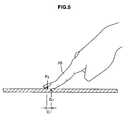
- FIGS. 5 to 7are explanatory diagrams showing a relationship between the display panel 108 and the user's finger.
- FIG. 8is an explanatory diagram showing a region having a 3-value processed luminance value which is detected by the light reception sensor 120.
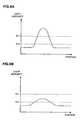
- FIG. 9is graphs showing distributions of luminance values (light intensities).
- FIG. 9Ashows a distribution of the luminance values on the line A-A
- FIG. 9Bshows a distribution of the luminance values on the line B-B.
- the information processing apparatus 100displays various items such as images or menu screens on the display panel 108 as a user interface based on image data (step S101).
- a software keyboard 140is displayed on the display panel 108.
- the light reception processing unit 122performs a light reception processing based on the light detected by the light reception sensor 120 (step S102).
- the finger 10 or hand, or one end of the stylusmakes closer to the screen and the other end is away from the screen as compared with the one end as shown in FIG. 5 .
- the tip of the finger 10fingertip
- the other part of the fingers 10is away from the screen.
- control unit 102calculates the luminance value of each pixel of the image signal generated in the light reception processing unit 122 and 3-value processes the luminance value.
- the 3-value processingsets two predetermined threshold values and summarizes the luminance values having various distributions as shown in FIG. 9 into the three values depending on the threshold values.
- the threshold valuescan be set depending on various conditions.
- a region 152has a strong luminance value and a region 154 has a middle luminance value.
- a region having a weak luminance valueis the regions other than the region 152 and the region 154.
- the region 152is where the operation object such as the tip of the finger 10 is closest to the screen, and the region 154 corresponds to the finger 10 away from the screen as compared with the tip of the finger 10.
- the information processing apparatus 100can determine that a user's operation has been made and the proximity to the screen has occurred. Subsequently, the information processing apparatus 100 detects the proximity at the weak threshold value (step S104). When the proximity at the weak threshold value is detected, it can be determined that the user points the screen by the finger 10 or the like in a predetermined direction.
- the proximity detection unit 161calculates the respective centroid positions of the region 152 and the region 154.
- a first centroid G 1 shown in FIG. 8is the centroid position of the region 152
- a second centroid G 2is the centroid position of the region 154.
- the finger coordinate calculation unit 162calculates the first centroid G 1 calculated by the proximity detection unit 161 as the contact position or proximity position based on the first centroid G 1 (step S105).
- the coordinate of the first centroid G 1is a temporary representative point of the position at which the operation object contacts or is proximate to the surface of the display panel 108.
- the coordinate of the first centroid G 1is different from the user-intended contact or proximity point in many cases.
- the corrected finger coordinateis calculated as follows to calculate the finger coordinate close to the user-intended contact or proximity point.
- the angle calculation unit 163calculates a direction of the straight line connecting the first centroid G 1 and the second centroid G 2 based on the centroids G 1 and G 2 (step S106). For example, the angle calculation unit 163 calculates an angle ⁇ (see FIG. 8 ) of the straight line D 1 connecting the first centroid and the second centroid relative to the vertical direction D 0 in the screen. In the example shown in FIG. 6 , the angle formed between the vertical direction D 0 in the screen and the straight line D 1 connecting the first centroid and the second centroid is ⁇ 1 . In the example shown in FIG. 7 , the angle between the vertical direction D 0 in the screen and the straight line D 1 connecting the first centroid and the second centroid is ⁇ 2 .
- the straight line D 1 connecting the first centroid and the second centroidcorresponds to the direction of the finger 10. Therefore, the direction in which the finger 10 points the display panel 108 can be numerically expressed (angle ⁇ ).
- the offset amount calculation unit 164calculates the amount of offset C 1 based on the distance L 1 between the first centroid G 1 and the second centroid G 2 calculated in the proximity detection unit 161 as shown in FIG. 8 (step S107).
- the corrected finger coordinate calculation unit 165calculates a pointed position different from the contact position or proximity position based on the contact position or proximity position (first centroid G 1 ) calculated in the finger coordinate calculation unit 162, and the angle ⁇ of the direction of the straight line connecting the first centroid G 1 and the second centroid G 2 (step S108).
- the pointed position different from the contact position or proximity positionis a corrected finger coordinate.
- the corrected finger coordinate calculation unit 165calculates a position on the straight line to which the contact position or proximity position calculated in the finger coordinate calculation unit 162 is moved by the amount of offset C 1 as a pointed position P 2 .
- the pointed position P 2is closer to the user-intended contact or proximity position as compared with the contact or proximity position calculated from the first centroid G 1 or the like.
- the offset amount calculation unit 164may calculate the distance between one end of the first region 152 at which the straight line D 1 connecting the first centroid G 1 and the second centroid G 2 crosses the boundary of the first region 152 and the first centroid G 1 as the amount of offset.
- the corrected finger coordinate calculation unit 165calculates a position on the straight line to which the contact position or proximity position calculated in the finger coordinate calculation unit 162 is moved by the amount of offset as a pointed position P 1 (see FIG. 8 ).
- the pointed position P 1is closer to the user-intended contact or proximity position as compared with the contact or proximity position calculated from the first centroid G 1 or the like.
- a display processingis performed on various displays displayed on the display panel 108 based on the corrected finger coordinate (step S109).
- the software keyboard 140is displayed in three stages as shown in FIG. 4 .
- a contact or proximity to a key button at the middle stagemay be detected.
- the distance between the buttonsis short, erroneous detection may occur to right and left key buttons of the intended key button.
- the angle ⁇ formed by the finger 10 relative to the vertical direction D 0 in the screencan be seen.
- the contact or proximity to the touch panelis detected as a region having a certain area on the touch panel.
- the centroid of the contact region or proximity region having a certain areawas calculated and the calculated centroid position has been determined as the representative point of the contact or proximity points.
- the point which has been determined to be in contact or proximate to the touch panel based on the centroid of the regionmay be different from a user-intended contact or proximity point to the touch panel.
- a button different from the user-intended buttonmay be selected due to how to hold the touch panel or a length of a user's nail.
- the pointed position close to the user-intended contact or proximity positioncan be calculated instead of the contact or proximity position detected between the user's finger 10 and the display panel 108. Consequently, user's discomfort can be reduced and erroneous operation such as tapping of an erroneous display button on the display panel 108 can be decreased.
- the proximity detection unit 161calculates a luminance value as a proximity value for one example of the proximity value obtaining unit in the above embodiment, but the present disclosure is not limited to the example.
- the proximity value obtaining unitis, for example, an electrostatic capacitance touch panel, which may include the electrostatic capacitance detection unit and the proximity value calculation unit.
- the electrostatic capacitance detection unitdetects an electrostatic capacitance between a user's finger (operation object) and the surface of the display unit.
- the proximity value calculation unitcalculates a change in the detected electrostatic capacitance as the proximity value.
- the proximity detection unit 161 of the control unit 102 3-valueprocesses the proximity value based on the calculated proximity value and calculates the first region and the second region.
- the proximity value obtaining unitmay be a sensitive touch panel and may calculate a proximity value depending on a detected pressure.
- the proximity valueis subjected to the 3-value processing depending on the degree of the pressure, thereby calculating the first region and the second region.
- a contact direction of a fingercan be known depending on the contact pressure of the user's finger on the screen.
- the respective centroids of the calculated first region and second regionare calculated in the present embodiment, but the present disclosure is not limited to the example.
- the center of a line connecting one end of a region and the other end thereofmay be employed other than the centroid if it is a representative value of the regions capable of calculating a direction connecting the two regions.
Landscapes
- Engineering & Computer Science (AREA)
- General Engineering & Computer Science (AREA)
- Theoretical Computer Science (AREA)
- Human Computer Interaction (AREA)
- Physics & Mathematics (AREA)
- General Physics & Mathematics (AREA)
- Position Input By Displaying (AREA)
- User Interface Of Digital Computer (AREA)
- Controls And Circuits For Display Device (AREA)
Description
- The present invention relates to an information processing apparatus and information processing method.
- A display device includes a touch panel (touch screen) in which an electrostatic capacitance or resistive touch sensor is provided on a surface of a display unit such as liquid crystal display. With the touch panel, the user can touch the screen of the display unit to input information into the information processing apparatus so that the user can easily manipulate the information processing apparatus.
- A capacitive multi-touch screen is for example disclosed in
WO 2005/114369A . - A touch panel technique other than electrostatic capacitance or resistive type is disclosed as a display device for detecting an operation near the display unit. For example, Japanese Patent Application Laid-Open No.
2006-276223 11-24839 3968477 2008-146165 - In the related art, a contact or proximity to a touch panel is detected as a region occupying a certain area on the touch panel. Thus, in order to calculate a representative point of the contact or proximity on the touch panel, the centroid of the contact region or proximity region having a certain area is calculated to determine the calculated centroid position as the representative point of the contact or proximity.
- However, there has been an issue that the point which is determined as being contacted on or proximate to the touch panel based on the centroid of the region is different from a point which a user intends to contact or be proximate to. For example, when a plurality of user-selectable buttons are adjacently displayed on a screen of the touch panel, a different button from a user-intended button may be selected due to how to hold the touch panel or a length of a user's nail.
- In order to avoid the above issues, in consideration of how to hold the touch panel or use's usage, it may be possible to assume user's intention to a certain degree and to calculate a different point from an actually-detected contact point or proximity point as a user-intended point depending on a detection position on the screen. However, the touch panel can be variously utilized such as vertically, horizontally, upside down. Thus, it was difficult to previously assume how to hold the touch panel or its usage and to correct the contact point or proximity point based on the assumption.
- Several approaches for improving touch pointing based on the detected orientation of an object touching a touch panel are known.
- For example,
US 2007/0097096A discloses a touch screen interaction method wherein a direct targeting mode and an offset targeting mode is implemented based on the size, shape and orientation of the area where a figures is touching the touch screen. US 2007/0300182A describes a user interface for a touch screen device where the orientation of the object touching the screen determines the orientation and the position of a displayed user interface element.- The present invention has been made in view of the above issues, and it is desirable to provide a novel and improved information processing apparatus and information processing method capable of correcting a contact position or proximity position not to a detected contact position or proximity position but to a user-intended contact position or proximity position with high accuracy.
- According to the present invention, there is provided an information processing apparatus according to
Claim 1. - Furthermore, there is provided an information processing method according to Claim 2.
- According to the embodiments of the present invention, a contact position or proximity position can be corrected to be closer not to a detected contact position or proximity position but to a user-intended contact position or proximity position with high accuracy.
- Various respective aspects and features of the invention are defined in the appended claims.
- Embodiments of the invention will now be described with reference to the accompanying drawings, throughout which like parts are referred to by like references, and in which:
FIG. 1 is a block diagram showing an information processing apparatus according to one embodiment of the present invention;FIG. 2 is an explanatory diagram showing pixels of a display panel according to the embodiment;FIG. 3 is a flowchart showing an operation of the information processing apparatus according to the embodiment;FIG. 4 is an explanatory diagram showing an image displayed on the display panel and a user's operation;FIG. 5 is an explanatory diagram showing a relationship between the display panel and a user's finger;FIG. 6 is an explanatory diagram showing a relationship between the display panel and a user's finger;FIG. 7 is an explanatory diagram showing a relationship between the display panel and a user's finger;FIG. 8 is an explanatory diagram showing a region having a 3-value processed luminance value which is detected by a light reception sensor; andFIG. 9 is graphs showing distributions of luminance values (light intensity).- Hereinafter, preferred embodiments of the present invention will be described in detail with reference to the appended drawings. Note that, in this specification and the appended drawings, structural elements that have substantially the same function and structure are denoted with the same reference numerals, and repeated explanation of these structural elements is omitted.
- 1. Structure of one embodiment
- 2. Operation of one embodiment
- At first, an
information processing apparatus 100 according to one embodiment of the present invention will be described.FIG. 1 is a block diagram showing theinformation processing apparatus 100 according to the present embodiment. - The
information processing apparatus 100 according to the present embodiment includes acontrol unit 102, amemory 104, astorage 106, an input I/F 107, an imagesignal processing unit 114, adisplay panel 108, adisplay control unit 112, a speech output I/F 116, a lightreception processing unit 122 and the like, for example. There will be described a case in which thedisplay panel 108 is integrally provided in theinformation processing apparatus 100 in the present embodiment, but the present invention can be applied to a case in which theinformation processing apparatus 100 and thedisplay panel 108 are separately provided. - The
information processing apparatus 100 is a personal computer, audio player, media player, PDA (personal digital assistant), cell phone, digital camera or the like, for example. - The
control unit 102 has a microcomputer which is configured in combination with a CPU (Central Processing Unit), a ROM (Read Only Memory), a RAM (Random Access Memory) and the like. Thecontrol unit 102 functions as a calculation processing device and a control device by programs, and controls the above respective constituents in theinformation processing apparatus 100. A signal is input into thecontrol unit 102 from thetouch panel 112 receiving an operation from outside. - The
memory 104 is configured with a storage unit such as RAM, ROM or cache memory, and has a function of temporarily storing therein data relating to the processing of the CPU of thecontrol unit 102 or operation programs of the CPU. - The
storage 106 is, for example, a hard disk, optical disk, flash memory or the like, and is a storage unit for storing therein data for a long time. Thestorage 106 stores therein music data or video data such as videos or photographs, for example. Thestorage 106 stores therein the music data or the video data through a data reception control processing and accumulation control processing in thecontrol unit 102. - The input I/
F 107 is, for example, a USB terminal, IEEE 1394 terminal or the like, and is an interface which is connectable to an external device. Various items of information or instructions are input into theinformation processing apparatus 100 via the input I/F 107. - The image
signal processing unit 114 performs a signal processing on an image signal generated in the lightreception processing unit 122. The imagesignal processing unit 114 performs various required signal processings such as resolution conversion for converting an image signal into the number of pixels of thedisplay unit 110, luminance correction, color correction and gamma correction. - The
display panel 108 includes, for example, thedisplay unit 110, thelight reception sensor 120 and the like, and thelight reception sensor 120 detects an operation object such as a user's finger or hand to accept the user's operation. Thedisplay panel 108 according to the present embodiment does not need to contact the screen unlike the touch panel, and detects a proximity to the screen to accept the user's operation. Then, thedisplay panel 108 selects an item displayed on the screen, scrolls the screen or changes a zoom-in or zoom-out display in response to the user's operation. - The
display unit 110 is a liquid crystal display, for example, and is controlled by thedisplay control unit 112. Thedisplay unit 110 displays various menu screens or images based on image data. Thelight reception sensor 120 is one example of a light reception unit, which receives a light incident into the display screen of thedisplay unit 110 from outside to convert the received light into an electric signal. Thelight reception sensor 120 sends the generated electric signal to the lightreception processing unit 122. - The speech output I/F 116 is, for example, a terminal for a phone plug or the like, and is connected to an external device such as headphone or speaker. The speech output I/
F 116 outputs reproduced speech data to the external device. FIG. 2 is an explanatory diagram showing pixels of thedisplay panel 108 according to the present embodiment. A plurality of pixel sets 130 are arranged in thedisplay panel 108 in a matrix manner. The pixel set 130 is provided with ared display pixel 110R, agreen display pixel 110G, ablue display pixel 110B, which are light emitting elements, and alight reception sensor 120. Thedisplay pixels light reception sensor 120 are adjacently arranged in onepixel set 130. The arrangement of pixels is not limited to the example shown inFIG. 2 and other arrangement may be employed.- When the operation object such as user's finger or hand makes close to the display screen by the
display panel 108 according to the present embodiment, theinformation processing apparatus 100 can detect the operation object. - The
display control unit 112 utilizes an input image signal to drive thedisplay unit 110. Thedisplay control unit 112 performs a display processing on the image signal received from the imagesignal processing unit 114. Further, thedisplay control unit 112 combines the display data and generates user-viewable data in thedisplay unit 110. The data generated in thedisplay control unit 112 is output to thedisplay unit 110. - The light
reception processing unit 122 receives the electric signal from thelight reception sensor 120 to perform A/D conversion processing or the like, and generates an image signal for each pixel. Thus, the image signal processing is enabled in the imagesignal processing unit 114 and various operations can be performed based on the image signal in thecontrol unit 102. - The
control unit 102 of theinformation processing apparatus 100 according to the present embodiment will be described below. Thecontrol unit 102 includes aproximity detection unit 161, a finger coordinatecalculation unit 162, anangle calculation unit 163, an offsetamount calculation unit 164, a corrected finger coordinatecalculation unit 165 and the like. - The
proximity detection unit 161 is one example of a proximity value obtaining unit, which calculates a luminance value for each pixel based on the image signal generated by the lightreception processing unit 122 to calculate the luminance value as a proximity value. The proximity value calculated by theproximity detection unit 161 is a value of the contact or proximity between the operation object and the surface of thedisplay panel 108. - The
proximity detection unit 161 is one example of a region detection unit, which 3-value processes the luminance value to detect a first region and a second region different from the first region for the detected object depending on the 3-value processed luminance value. Theproximity detection unit 161 is one example of a centroid position calculation unit, which calculates positions of the respective centroids of the first region and the second region. - The finger coordinate
calculation unit 162 is one example of a position calculation unit, which calculates the first centroid calculated by theproximity detection unit 161 as the contact position or proximity position. The coordinate of the first centroid is assumed as a representative point at which the operation object contacts or is proximate to the surface of thedisplay panel 108. The representative point of the contact or proximity positions to the surface of thedisplay panel 108 is not limited to the first centroid and may be assumed as a middle point between one end of the first region and the other end thereof, for example. - The
angle calculation unit 163 is one example of a linear direction calculation unit, which calculates a direction of a straight line connecting a first centroid as the centroid of the first region calculated in theproximity detection unit 161 and a second centroid as the centroid of the second region. Theangle calculation unit 163 calculates an angle of the straight line connecting the first centroid and the second centroid relative to a downward (or upward) direction (vertical direction) on the screen, for example. The straight line connecting the first centroid and the second centroid corresponds to the direction of thefinger 10. - The offset
amount calculation unit 164 calculates the amount of offset based on the distance between the first centroid calculated in theproximity detection unit 161 and the second centroid, for example. For example, when the distance between the first centroid and the second centroid is longer, the user's finger is more horizontal to thedisplay panel 108. On the other hand, when the distance between the first centroid and the second centroid is shorter, the user's finger is more vertical to thedisplay panel 108. The offsetamount calculation unit 164 uses the characteristics to calculate the amount of offset. - The offset
amount calculation unit 164 may calculate the distance between one end of the first region at which the straight line connecting the first centroid and the second centroid crosses the boundary of the first region and the first centroid as the amount of offset. - The corrected finger coordinate
calculation unit 165 is one example of a pointed position calculation unit, which calculates a pointed position different from the contact position or proximity position based on the contact position or proximity position calculated in the finger coordinatecalculation unit 162 and the direction of the straight line connecting the first centroid and the second centroid calculated in theproximity detection unit 161. For example, the corrected finger coordinatecalculation unit 165 calculates a position on the straight line to which the contact position or proximity position calculated in the finger coordinatecalculation unit 162 is moved by the amount of offset as the pointed position. The amount of offset used by the corrected finger coordinatecalculation unit 165 is the amount of offset calculated by the offsetamount calculation unit 164. The pointed position is closer to the user-intended contact or proximity position as compared with the contact or proximity position calculated from the first centroid. - An operation of the
information processing apparatus 100 according to the present embodiment will be described below. FIG. 3 is a flowchart showing the operation of theinformation processing apparatus 100 according to the present embodiment.FIG. 4 is an explanatory diagram showing an image displayed on thedisplay panel 108 and a user's operation.FIGS. 5 to 7 are explanatory diagrams showing a relationship between thedisplay panel 108 and the user's finger.FIG. 8 is an explanatory diagram showing a region having a 3-value processed luminance value which is detected by thelight reception sensor 120.FIG. 9 is graphs showing distributions of luminance values (light intensities).FIG. 9A shows a distribution of the luminance values on the line A-A andFIG. 9B shows a distribution of the luminance values on the line B-B.- At first, the
information processing apparatus 100 displays various items such as images or menu screens on thedisplay panel 108 as a user interface based on image data (step S101). In the example shown inFIG. 4 , asoftware keyboard 140 is displayed on thedisplay panel 108. - When the user makes the
finger 10 or hand, or an operation object such as a stylus closer to the screen of thedisplay panel 108 as shown inFIG. 4 , the lightreception processing unit 122 performs a light reception processing based on the light detected by the light reception sensor 120 (step S102). When the user points an operation object on the screen (such as each key button of the software keyboard 140), thefinger 10 or hand, or one end of the stylus makes closer to the screen and the other end is away from the screen as compared with the one end as shown inFIG. 5 . In the following, there will be described a case in which the tip of the finger 10 (fingertip) is closest to the screen and the other part of thefingers 10 is away from the screen. - Next, the
control unit 102 calculates the luminance value of each pixel of the image signal generated in the lightreception processing unit 122 and 3-value processes the luminance value. The 3-value processing sets two predetermined threshold values and summarizes the luminance values having various distributions as shown inFIG. 9 into the three values depending on the threshold values. The threshold values can be set depending on various conditions. - When the user points the screen by his/her
finger 10, the distribution of the luminance values as shown inFIG. 8 can be obtained. Aregion 152 has a strong luminance value and aregion 154 has a middle luminance value. A region having a weak luminance value is the regions other than theregion 152 and theregion 154. Theregion 152 is where the operation object such as the tip of thefinger 10 is closest to the screen, and theregion 154 corresponds to thefinger 10 away from the screen as compared with the tip of thefinger 10. - When a luminance value beyond the strong threshold value is detected (step S103), the
information processing apparatus 100 can determine that a user's operation has been made and the proximity to the screen has occurred. Subsequently, theinformation processing apparatus 100 detects the proximity at the weak threshold value (step S104). When the proximity at the weak threshold value is detected, it can be determined that the user points the screen by thefinger 10 or the like in a predetermined direction. - Then, the
proximity detection unit 161 calculates the respective centroid positions of theregion 152 and theregion 154. A first centroid G1 shown inFIG. 8 is the centroid position of theregion 152, and a second centroid G2 is the centroid position of theregion 154. - Next, the finger coordinate
calculation unit 162 calculates the first centroid G1 calculated by theproximity detection unit 161 as the contact position or proximity position based on the first centroid G1 (step S105). The coordinate of the first centroid G1 is a temporary representative point of the position at which the operation object contacts or is proximate to the surface of thedisplay panel 108. However, the coordinate of the first centroid G1 is different from the user-intended contact or proximity point in many cases. Thus, in the present embodiment, the corrected finger coordinate is calculated as follows to calculate the finger coordinate close to the user-intended contact or proximity point. - The
angle calculation unit 163 calculates a direction of the straight line connecting the first centroid G1 and the second centroid G2 based on the centroids G1 and G2 (step S106). For example, theangle calculation unit 163 calculates an angle θ (seeFIG. 8 ) of the straight line D1 connecting the first centroid and the second centroid relative to the vertical direction D0 in the screen. In the example shown inFIG. 6 , the angle formed between the vertical direction D0 in the screen and the straight line D1 connecting the first centroid and the second centroid is θ1. In the example shown inFIG. 7 , the angle between the vertical direction D0 in the screen and the straight line D1 connecting the first centroid and the second centroid is θ2. The straight line D1 connecting the first centroid and the second centroid corresponds to the direction of thefinger 10. Therefore, the direction in which thefinger 10 points thedisplay panel 108 can be numerically expressed (angle θ). - Furthermore, the offset
amount calculation unit 164 calculates the amount of offset C1 based on the distance L1 between the first centroid G1 and the second centroid G2 calculated in theproximity detection unit 161 as shown inFIG. 8 (step S107). - Next, the corrected finger coordinate
calculation unit 165 calculates a pointed position different from the contact position or proximity position based on the contact position or proximity position (first centroid G1) calculated in the finger coordinatecalculation unit 162, and the angle θ of the direction of the straight line connecting the first centroid G1 and the second centroid G2 (step S108). The pointed position different from the contact position or proximity position is a corrected finger coordinate. For example, the corrected finger coordinatecalculation unit 165 calculates a position on the straight line to which the contact position or proximity position calculated in the finger coordinatecalculation unit 162 is moved by the amount of offset C1 as a pointed position P2. The pointed position P2 is closer to the user-intended contact or proximity position as compared with the contact or proximity position calculated from the first centroid G1 or the like. - In step S107, the offset
amount calculation unit 164 may calculate the distance between one end of thefirst region 152 at which the straight line D1 connecting the first centroid G1 and the second centroid G2 crosses the boundary of thefirst region 152 and the first centroid G1 as the amount of offset. At this time, in step S108, the corrected finger coordinatecalculation unit 165 calculates a position on the straight line to which the contact position or proximity position calculated in the finger coordinatecalculation unit 162 is moved by the amount of offset as a pointed position P1 (seeFIG. 8 ). The pointed position P1 is closer to the user-intended contact or proximity position as compared with the contact or proximity position calculated from the first centroid G1 or the like. - Finally, a display processing is performed on various displays displayed on the
display panel 108 based on the corrected finger coordinate (step S109). For example, there will be described a case in which thesoftware keyboard 140 is displayed in three stages as shown inFIG. 4 . Even when the user intends to contact or make close to a key button at the upper stage, a contact or proximity to a key button at the middle stage may be detected. Further, when the distance between the buttons is short, erroneous detection may occur to right and left key buttons of the intended key button. According to the present embodiment, the angle θ formed by thefinger 10 relative to the vertical direction D0 in the screen can be seen. Thus, it is possible to calculate the corrected finger coordinate on the straight line corresponding to the direction of thefinger 10 and to calculate the pointed position closer to the user-intended contact or proximity position. Consequently, in the example shown inFIG. 4 , a key button at the middle stage is not selected and a key button at the upper stage is selected instead. Further, the right and left key buttons are not selected and the intended key button is selected. - In the related art, the contact or proximity to the touch panel is detected as a region having a certain area on the touch panel. Thus, in order to calculate a representative point of the contact or proximity points on the touch panel, the centroid of the contact region or proximity region having a certain area was calculated and the calculated centroid position has been determined as the representative point of the contact or proximity points.
- However, the point which has been determined to be in contact or proximate to the touch panel based on the centroid of the region may be different from a user-intended contact or proximity point to the touch panel. For example, when the user-selectable buttons are adjacently displayed on the screen of the touch panel, a button different from the user-intended button may be selected due to how to hold the touch panel or a length of a user's nail.
- On the other hand, according to the present embodiment, the pointed position close to the user-intended contact or proximity position can be calculated instead of the contact or proximity position detected between the user's
finger 10 and thedisplay panel 108. Consequently, user's discomfort can be reduced and erroneous operation such as tapping of an erroneous display button on thedisplay panel 108 can be decreased. - It should be understood by those skilled in the art that various modifications, combinations, sub-combinations and alterations may occur depending on design requirements and other factors insofar as they are within the scope of the appended claims or the equivalents thereof.
- For example, there has been described the case in which the
proximity detection unit 161 calculates a luminance value as a proximity value for one example of the proximity value obtaining unit in the above embodiment, but the present disclosure is not limited to the example. For example, the proximity value obtaining unit is, for example, an electrostatic capacitance touch panel, which may include the electrostatic capacitance detection unit and the proximity value calculation unit. The electrostatic capacitance detection unit detects an electrostatic capacitance between a user's finger (operation object) and the surface of the display unit. The proximity value calculation unit calculates a change in the detected electrostatic capacitance as the proximity value. For example, it is possible to calculate whether a finger contacts the surface of the display unit or how much they are distant from each other depending on the change in the electrostatic capacitance. Then, similarly to the above embodiment, theproximity detection unit 161 of thecontrol unit 102 3-value processes the proximity value based on the calculated proximity value and calculates the first region and the second region. - The proximity value obtaining unit may be a sensitive touch panel and may calculate a proximity value depending on a detected pressure. The proximity value is subjected to the 3-value processing depending on the degree of the pressure, thereby calculating the first region and the second region. For example, a contact direction of a finger can be known depending on the contact pressure of the user's finger on the screen.
- The respective centroids of the calculated first region and second region are calculated in the present embodiment, but the present disclosure is not limited to the example. For example, the center of a line connecting one end of a region and the other end thereof may be employed other than the centroid if it is a representative value of the regions capable of calculating a direction connecting the two regions.
- There has been described the
software keyboard 140 as shown inFIG. 4 to be displayed on thedisplay panel 108 for the display processing in the above embodiment, but the present invention is not limited to the example. For example, user-selectable displays such as various buttons, slider, text or browser link can be applied to other display.
Claims (2)
- An information processing apparatus comprising:a display unit (108) that displays an image on a screen based on image data;a proximity value obtaining unit (161) that obtains a proximity value for each of a plurality of pixels on the screen, each proximity value being indicative of a contact or proximity between an operation object and a surface of the display unit, wherein the proximity value obtaining unit comprises a light reception unit (120) that receives a light incident into the surface of the display unit from outside and converts the received light into an electric signal, and a luminance value calculation unit (122) that calculates a luminance value for each pixel as the proximity value from the electric signal;a region detection unit (161) that 3-value processes the proximity values, the 3-value processing setting two predetermined threshold values and summarizing the values into three values depending on the predetermined threshold values, and that detects a first region and a second region different from the first region depending on the 3-value processed proximity values;a centroid position calculation unit (161) that calculates positions of respective centroids of the first region and the second region;a linear direction calculation unit (163) that calculates a direction of a straight line connecting a first centroid as the centroid of the first region and a second centroid as the centroid of the second region;a position calculation unit (162) that calculates a contact position or proximity position between the operation object and the surface of the display unit based on the proximity values;a pointed position calculation unit (165) that calculates a pointed position different from the contact position or the proximity position based on the contact position or the proximity position and the direction of the straight line connecting the first centroid and the second centroid, wherein the position calculation unit (162) calculates the first centroid as the contact position or the proximity position, andthe pointed position calculation unit (165) calculates a position on the straight line to which the contact position or the proximity position is moved by an amount of offset as the pointed position,the apparatus beingcharacterized by further comprisingan offset amount calculation unit (164) that calculates the amount of offset based on a distance between the first centroid and the second centroid.
- An information processing method comprising the steps of:displaying an image on a screen based on image data by display unit (108);obtaining a proximity value for each of a plurality of pixels on the screen by a proximity value obtaining unit (161), each proximity value being indicative of a contact or proximity between an operation object and a surface of the display unit, the step of obtaining a proximity value comprising the steps ofreceiving a light incident into the surface of the display unit from outside and converts the received light into an electric signal, andcalculating a luminance value for each pixel as the proximity values from the electric signal;3-value processing the proximity values, the 3-value processing setting two predetermined threshold values and summarising the values into three values depending on the predetermined threshold value, and detecting a first region and a second region different from the first region depending on the 3-value processed proximity values by a region detection unit (161);calculating positions of respective centroids of the first region and the second region by a centroid position calculation unit (161);calculating a direction of a straight line connecting a first centroid as the centroid of the first region and a second centroid as the centroid of the second region by a linear direction calculation unit (163);calculating a contact position or proximity position between the operation object and the surface of the display unit based on the proximity values by a position calculation unit (162);calculating a pointed position different from the contact position or the proximity position based on the contact position or the proximity position and the direction of the straight line connecting the first centroid and the second centroid by a pointed position calculation unit (165), wherein the contact position or the proximity position is calculated as the first centroid by the position calculation unit (162) and wherein further a position is calculated by the pointed position calculation unit (165) on the straight line to which the contact position or the proximity position is moved by an amount of offset as the pointed position the method beingcharacterized by the further step of ;calculating the amount of offset based on a distance between the first and second centroid by an offset amount calculation unit (164).
Applications Claiming Priority (1)
| Application Number | Priority Date | Filing Date | Title |
|---|---|---|---|
| JP2008221856AJP4609557B2 (en) | 2008-08-29 | 2008-08-29 | Information processing apparatus and information processing method |
Publications (3)
| Publication Number | Publication Date |
|---|---|
| EP2166435A2 EP2166435A2 (en) | 2010-03-24 |
| EP2166435A3 EP2166435A3 (en) | 2010-08-04 |
| EP2166435B1true EP2166435B1 (en) | 2012-12-12 |
Family
ID=41404544
Family Applications (1)
| Application Number | Title | Priority Date | Filing Date |
|---|---|---|---|
| EP09251558ANot-in-forceEP2166435B1 (en) | 2008-08-29 | 2009-06-15 | Information processing apparatus and information processing method |
Country Status (4)
| Country | Link |
|---|---|
| US (1) | US8237678B2 (en) |
| EP (1) | EP2166435B1 (en) |
| JP (1) | JP4609557B2 (en) |
| CN (1) | CN101661349B (en) |
Families Citing this family (31)
| Publication number | Priority date | Publication date | Assignee | Title |
|---|---|---|---|---|
| JP4609543B2 (en)* | 2008-07-25 | 2011-01-12 | ソニー株式会社 | Information processing apparatus and information processing method |
| JP4743267B2 (en)* | 2008-12-12 | 2011-08-10 | ソニー株式会社 | Information processing apparatus, information processing method, and program |
| JP5269648B2 (en)* | 2009-03-02 | 2013-08-21 | パナソニック株式会社 | Portable terminal device and input device |
| WO2010113397A1 (en)* | 2009-03-31 | 2010-10-07 | 三菱電機株式会社 | Display input device |
| JP5545009B2 (en)* | 2010-04-28 | 2014-07-09 | ソニー株式会社 | Sensor device and information display device |
| CN102314258B (en)* | 2010-07-01 | 2013-10-23 | 原相科技股份有限公司 | Optical touch system, object position calculation device and object position calculation method |
| US9152287B2 (en) | 2010-08-05 | 2015-10-06 | Analog Devices, Inc. | System and method for dual-touch gesture classification in resistive touch screens |
| US20130027343A1 (en) | 2011-07-29 | 2013-01-31 | Analog Devices, Inc. | Position determination techniques in resistive touch screen applications |
| JP5510185B2 (en)* | 2010-08-20 | 2014-06-04 | ソニー株式会社 | Information processing apparatus, program, and display control method |
| JP5630160B2 (en)* | 2010-09-07 | 2014-11-26 | ソニー株式会社 | Information processing apparatus, information processing method, and computer program |
| JP5569271B2 (en)* | 2010-09-07 | 2014-08-13 | ソニー株式会社 | Information processing apparatus, information processing method, and program |
| JP5494423B2 (en) | 2010-11-02 | 2014-05-14 | ソニー株式会社 | Display device, position correction method, and program |
| JP5656652B2 (en)* | 2011-01-07 | 2015-01-21 | キヤノン株式会社 | Touch panel device and touch panel detection position correction method |
| JP2012221425A (en)* | 2011-04-13 | 2012-11-12 | Fujitsu Ten Ltd | Operation device |
| US20130119977A1 (en)* | 2011-11-11 | 2013-05-16 | Boris Leonid Sheikman | Sensing element for sensor assembly |
| JP2013206350A (en)* | 2012-03-29 | 2013-10-07 | Ntt Docomo Inc | Information processor, and method for correcting input place in the information processor |
| JP5904440B2 (en)* | 2012-04-20 | 2016-04-13 | シャープ株式会社 | Operation input device, operation input method and program |
| JP5798103B2 (en)* | 2012-11-05 | 2015-10-21 | 株式会社Nttドコモ | Terminal device, screen display method, program |
| US9645666B2 (en)* | 2012-11-22 | 2017-05-09 | Sharp Kabushiki Kaisha | Display device with touch panel attached |
| CN103092421B (en)* | 2013-01-28 | 2018-09-14 | 苏州瀚瑞微电子有限公司 | The modification method of touch panel linear error |
| JP5852050B2 (en)* | 2013-05-27 | 2016-02-03 | 株式会社ジャパンディスプレイ | Touch detection device, display device with touch detection function, and electronic device |
| JP6107968B2 (en)* | 2013-11-12 | 2017-04-05 | 富士通株式会社 | Display processing apparatus, display processing method, and display processing program |
| JP2015125705A (en)* | 2013-12-27 | 2015-07-06 | 船井電機株式会社 | Image display device |
| JP5947999B2 (en)* | 2014-02-10 | 2016-07-06 | レノボ・シンガポール・プライベート・リミテッド | Method, electronic device and computer program for improving operation accuracy for touch screen |
| JP5796648B2 (en)* | 2014-02-28 | 2015-10-21 | ソニー株式会社 | Information processing apparatus, information processing method, and information processing system |
| KR20150127989A (en)* | 2014-05-08 | 2015-11-18 | 삼성전자주식회사 | Apparatus and method for providing user interface |
| JP6324203B2 (en)* | 2014-05-14 | 2018-05-16 | キヤノン株式会社 | Information processing apparatus, control method therefor, program, and recording medium |
| JP5971817B2 (en) | 2014-06-20 | 2016-08-17 | インターナショナル・ビジネス・マシーンズ・コーポレーションInternational Business Machines Corporation | Information processing apparatus, program, and method |
| US10782825B2 (en)* | 2015-07-28 | 2020-09-22 | Hewlett-Packard Development Company, L.P. | Distinguishing non-input contact |
| EP3362884A4 (en)* | 2016-03-03 | 2019-06-26 | Hewlett-Packard Development Company, L.P. | INPUT AXIS ROTATIONS |
| TWI579826B (en)* | 2016-03-30 | 2017-04-21 | 佳世達科技股份有限公司 | Display device and oreration method thereof |
Family Cites Families (14)
| Publication number | Priority date | Publication date | Assignee | Title |
|---|---|---|---|---|
| JP3968477B2 (en) | 1997-07-07 | 2007-08-29 | ソニー株式会社 | Information input device and information input method |
| US7663607B2 (en)* | 2004-05-06 | 2010-02-16 | Apple Inc. | Multipoint touchscreen |
| JP2005234958A (en)* | 2004-02-20 | 2005-09-02 | Nissan Motor Co Ltd | Touch panel device |
| JP2006276223A (en)* | 2005-03-28 | 2006-10-12 | Sony Corp | Display apparatus and method |
| JP2007011228A (en)* | 2005-07-04 | 2007-01-18 | Toshiba Matsushita Display Technology Co Ltd | Flat display device |
| CN100429610C (en)* | 2006-01-19 | 2008-10-29 | 宏达国际电子股份有限公司 | Intuition type fluorescent screen controller |
| US20070097096A1 (en)* | 2006-03-25 | 2007-05-03 | Outland Research, Llc | Bimodal user interface paradigm for touch screen devices |
| US7552402B2 (en)* | 2006-06-22 | 2009-06-23 | Microsoft Corporation | Interface orientation using shadows |
| JP4834482B2 (en)* | 2006-07-24 | 2011-12-14 | 東芝モバイルディスプレイ株式会社 | Display device |
| JP2008097172A (en)* | 2006-10-10 | 2008-04-24 | Sony Corp | Display and display method |
| JP5191119B2 (en) | 2006-12-06 | 2013-04-24 | 株式会社ジャパンディスプレイウェスト | Display device, display device control method, and program |
| JP4453710B2 (en)* | 2007-03-19 | 2010-04-21 | セイコーエプソン株式会社 | Liquid crystal device, electronic apparatus and position detection method |
| JP4605170B2 (en)* | 2007-03-23 | 2011-01-05 | 株式会社デンソー | Operation input device |
| JP4609543B2 (en)* | 2008-07-25 | 2011-01-12 | ソニー株式会社 | Information processing apparatus and information processing method |
- 2008
- 2008-08-29JPJP2008221856Apatent/JP4609557B2/ennot_activeExpired - Fee Related
- 2009
- 2009-06-15EPEP09251558Apatent/EP2166435B1/ennot_activeNot-in-force
- 2009-08-28CNCN2009101715570Apatent/CN101661349B/ennot_activeExpired - Fee Related
- 2009-08-28USUS12/550,103patent/US8237678B2/ennot_activeExpired - Fee Related
Also Published As
| Publication number | Publication date |
|---|---|
| CN101661349A (en) | 2010-03-03 |
| EP2166435A2 (en) | 2010-03-24 |
| US20100053109A1 (en) | 2010-03-04 |
| JP2010055510A (en) | 2010-03-11 |
| JP4609557B2 (en) | 2011-01-12 |
| CN101661349B (en) | 2012-05-30 |
| EP2166435A3 (en) | 2010-08-04 |
| US8237678B2 (en) | 2012-08-07 |
Similar Documents
| Publication | Publication Date | Title |
|---|---|---|
| EP2166435B1 (en) | Information processing apparatus and information processing method | |
| US9442601B2 (en) | Information processing apparatus and information processing method | |
| US8970518B2 (en) | Click position control apparatus, click position control method, and touch sensor system | |
| US8648816B2 (en) | Information processing apparatus, threshold value setting method, and threshold value setting program | |
| US9250790B2 (en) | Information processing device, method of processing information, and computer program storage device | |
| US20080288895A1 (en) | Touch-Down Feed-Forward in 30D Touch Interaction | |
| US9569099B2 (en) | Method and apparatus for displaying keypad in terminal having touch screen | |
| US20100149122A1 (en) | Touch Panel with Multi-Touch Function and Method for Detecting Multi-Touch Thereof | |
| CN100383717C (en) | Portable terminal and data input method therefor | |
| US20120013645A1 (en) | Display and method of displaying icon image | |
| US20140232825A1 (en) | Calibration of a 3D camera | |
| US9710096B2 (en) | Information processing apparatus and method, and program for removing displayed objects based on a covered region of a screen | |
| JP5713180B2 (en) | Touch panel device that operates as if the detection area is smaller than the display area of the display. | |
| US20150002433A1 (en) | Method and apparatus for performing a zooming action | |
| CN106909334A (en) | A kind of method and mobile terminal for adjusting screen color temp | |
| TWI471762B (en) | Touch pen, electronic device and interactive operation method | |
| US20130113728A1 (en) | Single-point-multi-finger gestures for touch panel | |
| CN101751194A (en) | Touch panel with multi-point touch function and multi-point touch detection method | |
| CN110162257A (en) | Multiconductor touch control method, device, equipment and computer readable storage medium | |
| JP7069887B2 (en) | Display control method for mobile terminal devices and mobile terminal devices | |
| JP7087494B2 (en) | Display control method for mobile terminal devices and mobile terminal devices | |
| KR20210050652A (en) | Method for providing fingerprint recognition of mobile device | |
| CN104035628A (en) | virtual touch device | |
| KR20150008962A (en) | Mobile communication terminal and control method |
Legal Events
| Date | Code | Title | Description |
|---|---|---|---|
| PUAI | Public reference made under article 153(3) epc to a published international application that has entered the european phase | Free format text:ORIGINAL CODE: 0009012 | |
| 17P | Request for examination filed | Effective date:20090701 | |
| AK | Designated contracting states | Kind code of ref document:A2 Designated state(s):AT BE BG CH CY CZ DE DK EE ES FI FR GB GR HR HU IE IS IT LI LT LU LV MC MK MT NL NO PL PT RO SE SI SK TR | |
| AX | Request for extension of the european patent | Extension state:AL BA RS | |
| PUAL | Search report despatched | Free format text:ORIGINAL CODE: 0009013 | |
| AK | Designated contracting states | Kind code of ref document:A3 Designated state(s):AT BE BG CH CY CZ DE DK EE ES FI FR GB GR HR HU IE IS IT LI LT LU LV MC MK MT NL NO PL PT RO SE SI SK TR | |
| AX | Request for extension of the european patent | Extension state:AL BA RS | |
| RIC1 | Information provided on ipc code assigned before grant | Ipc:G06F 3/041 20060101AFI20091217BHEP Ipc:G06F 3/048 20060101ALI20100625BHEP | |
| 17Q | First examination report despatched | Effective date:20100714 | |
| REG | Reference to a national code | Ref country code:DE Ref legal event code:R079 Ref document number:602009011874 Country of ref document:DE Free format text:PREVIOUS MAIN CLASS: G06F0003041000 Ipc:G06F0003042000 | |
| RIC1 | Information provided on ipc code assigned before grant | Ipc:G06F 3/048 20060101ALI20120523BHEP Ipc:G06F 3/041 20060101ALI20120523BHEP Ipc:G06F 3/042 20060101AFI20120523BHEP | |
| GRAP | Despatch of communication of intention to grant a patent | Free format text:ORIGINAL CODE: EPIDOSNIGR1 | |
| GRAS | Grant fee paid | Free format text:ORIGINAL CODE: EPIDOSNIGR3 | |
| GRAA | (expected) grant | Free format text:ORIGINAL CODE: 0009210 | |
| AK | Designated contracting states | Kind code of ref document:B1 Designated state(s):AT BE BG CH CY CZ DE DK EE ES FI FR GB GR HR HU IE IS IT LI LT LU LV MC MK MT NL NO PL PT RO SE SI SK TR | |
| REG | Reference to a national code | Ref country code:GB Ref legal event code:FG4D | |
| REG | Reference to a national code | Ref country code:CH Ref legal event code:EP | |
| REG | Reference to a national code | Ref country code:AT Ref legal event code:REF Ref document number:588606 Country of ref document:AT Kind code of ref document:T Effective date:20121215 | |
| REG | Reference to a national code | Ref country code:IE Ref legal event code:FG4D | |
| REG | Reference to a national code | Ref country code:DE Ref legal event code:R096 Ref document number:602009011874 Country of ref document:DE Effective date:20130207 | |
| PG25 | Lapsed in a contracting state [announced via postgrant information from national office to epo] | Ref country code:LT Free format text:LAPSE BECAUSE OF FAILURE TO SUBMIT A TRANSLATION OF THE DESCRIPTION OR TO PAY THE FEE WITHIN THE PRESCRIBED TIME-LIMIT Effective date:20121212 Ref country code:ES Free format text:LAPSE BECAUSE OF FAILURE TO SUBMIT A TRANSLATION OF THE DESCRIPTION OR TO PAY THE FEE WITHIN THE PRESCRIBED TIME-LIMIT Effective date:20130323 Ref country code:SE Free format text:LAPSE BECAUSE OF FAILURE TO SUBMIT A TRANSLATION OF THE DESCRIPTION OR TO PAY THE FEE WITHIN THE PRESCRIBED TIME-LIMIT Effective date:20121212 Ref country code:FI Free format text:LAPSE BECAUSE OF FAILURE TO SUBMIT A TRANSLATION OF THE DESCRIPTION OR TO PAY THE FEE WITHIN THE PRESCRIBED TIME-LIMIT Effective date:20121212 Ref country code:NO Free format text:LAPSE BECAUSE OF FAILURE TO SUBMIT A TRANSLATION OF THE DESCRIPTION OR TO PAY THE FEE WITHIN THE PRESCRIBED TIME-LIMIT Effective date:20130312 | |
| REG | Reference to a national code | Ref country code:NL Ref legal event code:VDEP Effective date:20121212 | |
| REG | Reference to a national code | Ref country code:AT Ref legal event code:MK05 Ref document number:588606 Country of ref document:AT Kind code of ref document:T Effective date:20121212 | |
| REG | Reference to a national code | Ref country code:LT Ref legal event code:MG4D | |
| PG25 | Lapsed in a contracting state [announced via postgrant information from national office to epo] | Ref country code:GR Free format text:LAPSE BECAUSE OF FAILURE TO SUBMIT A TRANSLATION OF THE DESCRIPTION OR TO PAY THE FEE WITHIN THE PRESCRIBED TIME-LIMIT Effective date:20130313 Ref country code:SI Free format text:LAPSE BECAUSE OF FAILURE TO SUBMIT A TRANSLATION OF THE DESCRIPTION OR TO PAY THE FEE WITHIN THE PRESCRIBED TIME-LIMIT Effective date:20121212 Ref country code:LV Free format text:LAPSE BECAUSE OF FAILURE TO SUBMIT A TRANSLATION OF THE DESCRIPTION OR TO PAY THE FEE WITHIN THE PRESCRIBED TIME-LIMIT Effective date:20121212 | |
| PG25 | Lapsed in a contracting state [announced via postgrant information from national office to epo] | Ref country code:BG Free format text:LAPSE BECAUSE OF FAILURE TO SUBMIT A TRANSLATION OF THE DESCRIPTION OR TO PAY THE FEE WITHIN THE PRESCRIBED TIME-LIMIT Effective date:20130312 Ref country code:CZ Free format text:LAPSE BECAUSE OF FAILURE TO SUBMIT A TRANSLATION OF THE DESCRIPTION OR TO PAY THE FEE WITHIN THE PRESCRIBED TIME-LIMIT Effective date:20121212 Ref country code:BE Free format text:LAPSE BECAUSE OF FAILURE TO SUBMIT A TRANSLATION OF THE DESCRIPTION OR TO PAY THE FEE WITHIN THE PRESCRIBED TIME-LIMIT Effective date:20121212 Ref country code:IS Free format text:LAPSE BECAUSE OF FAILURE TO SUBMIT A TRANSLATION OF THE DESCRIPTION OR TO PAY THE FEE WITHIN THE PRESCRIBED TIME-LIMIT Effective date:20130412 Ref country code:SK Free format text:LAPSE BECAUSE OF FAILURE TO SUBMIT A TRANSLATION OF THE DESCRIPTION OR TO PAY THE FEE WITHIN THE PRESCRIBED TIME-LIMIT Effective date:20121212 Ref country code:AT Free format text:LAPSE BECAUSE OF FAILURE TO SUBMIT A TRANSLATION OF THE DESCRIPTION OR TO PAY THE FEE WITHIN THE PRESCRIBED TIME-LIMIT Effective date:20121212 Ref country code:EE Free format text:LAPSE BECAUSE OF FAILURE TO SUBMIT A TRANSLATION OF THE DESCRIPTION OR TO PAY THE FEE WITHIN THE PRESCRIBED TIME-LIMIT Effective date:20121212 | |
| PG25 | Lapsed in a contracting state [announced via postgrant information from national office to epo] | Ref country code:PT Free format text:LAPSE BECAUSE OF FAILURE TO SUBMIT A TRANSLATION OF THE DESCRIPTION OR TO PAY THE FEE WITHIN THE PRESCRIBED TIME-LIMIT Effective date:20130412 Ref country code:RO Free format text:LAPSE BECAUSE OF FAILURE TO SUBMIT A TRANSLATION OF THE DESCRIPTION OR TO PAY THE FEE WITHIN THE PRESCRIBED TIME-LIMIT Effective date:20121212 Ref country code:PL Free format text:LAPSE BECAUSE OF FAILURE TO SUBMIT A TRANSLATION OF THE DESCRIPTION OR TO PAY THE FEE WITHIN THE PRESCRIBED TIME-LIMIT Effective date:20121212 Ref country code:NL Free format text:LAPSE BECAUSE OF FAILURE TO SUBMIT A TRANSLATION OF THE DESCRIPTION OR TO PAY THE FEE WITHIN THE PRESCRIBED TIME-LIMIT Effective date:20121212 | |
| PLBE | No opposition filed within time limit | Free format text:ORIGINAL CODE: 0009261 | |
| STAA | Information on the status of an ep patent application or granted ep patent | Free format text:STATUS: NO OPPOSITION FILED WITHIN TIME LIMIT | |
| PG25 | Lapsed in a contracting state [announced via postgrant information from national office to epo] | Ref country code:DK Free format text:LAPSE BECAUSE OF FAILURE TO SUBMIT A TRANSLATION OF THE DESCRIPTION OR TO PAY THE FEE WITHIN THE PRESCRIBED TIME-LIMIT Effective date:20121212 | |
| 26N | No opposition filed | Effective date:20130913 | |
| PG25 | Lapsed in a contracting state [announced via postgrant information from national office to epo] | Ref country code:HR Free format text:LAPSE BECAUSE OF FAILURE TO SUBMIT A TRANSLATION OF THE DESCRIPTION OR TO PAY THE FEE WITHIN THE PRESCRIBED TIME-LIMIT Effective date:20121212 Ref country code:CY Free format text:LAPSE BECAUSE OF FAILURE TO SUBMIT A TRANSLATION OF THE DESCRIPTION OR TO PAY THE FEE WITHIN THE PRESCRIBED TIME-LIMIT Effective date:20121212 | |
| PG25 | Lapsed in a contracting state [announced via postgrant information from national office to epo] | Ref country code:IT Free format text:LAPSE BECAUSE OF FAILURE TO SUBMIT A TRANSLATION OF THE DESCRIPTION OR TO PAY THE FEE WITHIN THE PRESCRIBED TIME-LIMIT Effective date:20121212 | |
| REG | Reference to a national code | Ref country code:DE Ref legal event code:R097 Ref document number:602009011874 Country of ref document:DE Effective date:20130913 | |
| PG25 | Lapsed in a contracting state [announced via postgrant information from national office to epo] | Ref country code:MC Free format text:LAPSE BECAUSE OF FAILURE TO SUBMIT A TRANSLATION OF THE DESCRIPTION OR TO PAY THE FEE WITHIN THE PRESCRIBED TIME-LIMIT Effective date:20121212 | |
| REG | Reference to a national code | Ref country code:CH Ref legal event code:PL | |
| REG | Reference to a national code | Ref country code:IE Ref legal event code:MM4A | |
| PG25 | Lapsed in a contracting state [announced via postgrant information from national office to epo] | Ref country code:CH Free format text:LAPSE BECAUSE OF NON-PAYMENT OF DUE FEES Effective date:20130630 Ref country code:LI Free format text:LAPSE BECAUSE OF NON-PAYMENT OF DUE FEES Effective date:20130630 Ref country code:IE Free format text:LAPSE BECAUSE OF NON-PAYMENT OF DUE FEES Effective date:20130615 | |
| PG25 | Lapsed in a contracting state [announced via postgrant information from national office to epo] | Ref country code:MT Free format text:LAPSE BECAUSE OF FAILURE TO SUBMIT A TRANSLATION OF THE DESCRIPTION OR TO PAY THE FEE WITHIN THE PRESCRIBED TIME-LIMIT Effective date:20121212 | |
| REG | Reference to a national code | Ref country code:DE Ref legal event code:R084 Ref document number:602009011874 Country of ref document:DE | |
| REG | Reference to a national code | Ref country code:GB Ref legal event code:746 Effective date:20150420 | |
| REG | Reference to a national code | Ref country code:DE Ref legal event code:R084 Ref document number:602009011874 Country of ref document:DE Effective date:20150410 | |
| PG25 | Lapsed in a contracting state [announced via postgrant information from national office to epo] | Ref country code:TR Free format text:LAPSE BECAUSE OF FAILURE TO SUBMIT A TRANSLATION OF THE DESCRIPTION OR TO PAY THE FEE WITHIN THE PRESCRIBED TIME-LIMIT Effective date:20121212 | |
| PG25 | Lapsed in a contracting state [announced via postgrant information from national office to epo] | Ref country code:LU Free format text:LAPSE BECAUSE OF NON-PAYMENT OF DUE FEES Effective date:20130615 Ref country code:MK Free format text:LAPSE BECAUSE OF FAILURE TO SUBMIT A TRANSLATION OF THE DESCRIPTION OR TO PAY THE FEE WITHIN THE PRESCRIBED TIME-LIMIT Effective date:20121212 Ref country code:HU Free format text:LAPSE BECAUSE OF FAILURE TO SUBMIT A TRANSLATION OF THE DESCRIPTION OR TO PAY THE FEE WITHIN THE PRESCRIBED TIME-LIMIT; INVALID AB INITIO Effective date:20090615 | |
| REG | Reference to a national code | Ref country code:FR Ref legal event code:PLFP Year of fee payment:8 | |
| REG | Reference to a national code | Ref country code:FR Ref legal event code:PLFP Year of fee payment:9 | |
| REG | Reference to a national code | Ref country code:FR Ref legal event code:PLFP Year of fee payment:10 | |
| PGFP | Annual fee paid to national office [announced via postgrant information from national office to epo] | Ref country code:DE Payment date:20180625 Year of fee payment:10 | |
| PGFP | Annual fee paid to national office [announced via postgrant information from national office to epo] | Ref country code:FR Payment date:20180620 Year of fee payment:10 | |
| PGFP | Annual fee paid to national office [announced via postgrant information from national office to epo] | Ref country code:GB Payment date:20180620 Year of fee payment:10 | |
| REG | Reference to a national code | Ref country code:DE Ref legal event code:R119 Ref document number:602009011874 Country of ref document:DE | |
| GBPC | Gb: european patent ceased through non-payment of renewal fee | Effective date:20190615 | |
| PG25 | Lapsed in a contracting state [announced via postgrant information from national office to epo] | Ref country code:GB Free format text:LAPSE BECAUSE OF NON-PAYMENT OF DUE FEES Effective date:20190615 Ref country code:DE Free format text:LAPSE BECAUSE OF NON-PAYMENT OF DUE FEES Effective date:20200101 | |
| PG25 | Lapsed in a contracting state [announced via postgrant information from national office to epo] | Ref country code:FR Free format text:LAPSE BECAUSE OF NON-PAYMENT OF DUE FEES Effective date:20190630 |