EP2165727A2 - Laryngeal Mask Airway Device with Position Controlling Tab - Google Patents
Laryngeal Mask Airway Device with Position Controlling TabDownload PDFInfo
- Publication number
- EP2165727A2 EP2165727A2EP10150122AEP10150122AEP2165727A2EP 2165727 A2EP2165727 A2EP 2165727A2EP 10150122 AEP10150122 AEP 10150122AEP 10150122 AEP10150122 AEP 10150122AEP 2165727 A2EP2165727 A2EP 2165727A2
- Authority
- EP
- European Patent Office
- Prior art keywords
- cuff
- tab
- patient
- flange
- airway
- Prior art date
- Legal status (The legal status is an assumption and is not a legal conclusion. Google has not performed a legal analysis and makes no representation as to the accuracy of the status listed.)
- Withdrawn
Links
- 210000002409epiglottisAnatomy0.000claimsabstractdescription39
- 239000000463materialSubstances0.000claimsabstractdescription12
- 239000007787solidSubstances0.000claimsabstract3
- 239000002390adhesive tapeSubstances0.000claimsdescription9
- 239000004677NylonSubstances0.000claimsdescription2
- 229920001778nylonPolymers0.000claimsdescription2
- 238000003780insertionMethods0.000description13
- 230000037431insertionEffects0.000description13
- 210000005070sphincterAnatomy0.000description9
- 210000003484anatomyAnatomy0.000description4
- 238000001746injection mouldingMethods0.000description4
- 210000003437tracheaAnatomy0.000description4
- 230000000903blocking effectEffects0.000description3
- 210000004072lungAnatomy0.000description3
- 238000001514detection methodMethods0.000description2
- 239000000314lubricantSubstances0.000description2
- 239000004033plasticSubstances0.000description2
- 206010002091AnaesthesiaDiseases0.000description1
- 240000008100Brassica rapaSpecies0.000description1
- 208000003443UnconsciousnessDiseases0.000description1
- 230000037005anaesthesiaEffects0.000description1
- 238000001949anaesthesiaMethods0.000description1
- 230000003444anaesthetic effectEffects0.000description1
- 238000004873anchoringMethods0.000description1
- 238000004891communicationMethods0.000description1
- 238000012790confirmationMethods0.000description1
- 230000007423decreaseEffects0.000description1
- 230000000994depressogenic effectEffects0.000description1
- 210000005069earsAnatomy0.000description1
- 210000003238esophagusAnatomy0.000description1
- 239000012530fluidSubstances0.000description1
- 230000012447hatchingEffects0.000description1
- 230000033001locomotionEffects0.000description1
- 210000003800pharynxAnatomy0.000description1
- 239000004417polycarbonateSubstances0.000description1
- 229920000515polycarbonatePolymers0.000description1
- 230000001954sterilising effectEffects0.000description1
- 238000004659sterilization and disinfectionMethods0.000description1
Images


Classifications
- A—HUMAN NECESSITIES
- A61—MEDICAL OR VETERINARY SCIENCE; HYGIENE
- A61M—DEVICES FOR INTRODUCING MEDIA INTO, OR ONTO, THE BODY; DEVICES FOR TRANSDUCING BODY MEDIA OR FOR TAKING MEDIA FROM THE BODY; DEVICES FOR PRODUCING OR ENDING SLEEP OR STUPOR
- A61M16/00—Devices for influencing the respiratory system of patients by gas treatment, e.g. ventilators; Tracheal tubes
- A61M16/04—Tracheal tubes
- A61M16/0402—Special features for tracheal tubes not otherwise provided for
- A61M16/0409—Special features for tracheal tubes not otherwise provided for with mean for closing the oesophagus
- A—HUMAN NECESSITIES
- A61—MEDICAL OR VETERINARY SCIENCE; HYGIENE
- A61M—DEVICES FOR INTRODUCING MEDIA INTO, OR ONTO, THE BODY; DEVICES FOR TRANSDUCING BODY MEDIA OR FOR TAKING MEDIA FROM THE BODY; DEVICES FOR PRODUCING OR ENDING SLEEP OR STUPOR
- A61M16/00—Devices for influencing the respiratory system of patients by gas treatment, e.g. ventilators; Tracheal tubes
- A61M16/04—Tracheal tubes
- A61M16/0402—Special features for tracheal tubes not otherwise provided for
- A61M16/0418—Special features for tracheal tubes not otherwise provided for with integrated means for changing the degree of curvature, e.g. for easy intubation
- A—HUMAN NECESSITIES
- A61—MEDICAL OR VETERINARY SCIENCE; HYGIENE
- A61M—DEVICES FOR INTRODUCING MEDIA INTO, OR ONTO, THE BODY; DEVICES FOR TRANSDUCING BODY MEDIA OR FOR TAKING MEDIA FROM THE BODY; DEVICES FOR PRODUCING OR ENDING SLEEP OR STUPOR
- A61M16/00—Devices for influencing the respiratory system of patients by gas treatment, e.g. ventilators; Tracheal tubes
- A61M16/04—Tracheal tubes
- A61M16/0434—Cuffs
- A61M16/0445—Special cuff forms, e.g. undulated
- A—HUMAN NECESSITIES
- A61—MEDICAL OR VETERINARY SCIENCE; HYGIENE
- A61M—DEVICES FOR INTRODUCING MEDIA INTO, OR ONTO, THE BODY; DEVICES FOR TRANSDUCING BODY MEDIA OR FOR TAKING MEDIA FROM THE BODY; DEVICES FOR PRODUCING OR ENDING SLEEP OR STUPOR
- A61M16/00—Devices for influencing the respiratory system of patients by gas treatment, e.g. ventilators; Tracheal tubes
- A61M16/04—Tracheal tubes
- A61M16/0488—Mouthpieces; Means for guiding, securing or introducing the tubes
- A—HUMAN NECESSITIES
- A61—MEDICAL OR VETERINARY SCIENCE; HYGIENE
- A61M—DEVICES FOR INTRODUCING MEDIA INTO, OR ONTO, THE BODY; DEVICES FOR TRANSDUCING BODY MEDIA OR FOR TAKING MEDIA FROM THE BODY; DEVICES FOR PRODUCING OR ENDING SLEEP OR STUPOR
- A61M16/00—Devices for influencing the respiratory system of patients by gas treatment, e.g. ventilators; Tracheal tubes
- A61M16/04—Tracheal tubes
- A61M16/0402—Special features for tracheal tubes not otherwise provided for
- A61M16/0411—Special features for tracheal tubes not otherwise provided for with means for differentiating between oesophageal and tracheal intubation
Definitions
- the present inventionrelates to a laryngeal mask airway device, More specifically, the present invention relates to a laryngeal mask airway device having a tab disposed near the device's proximal end for facilitating position control of the device.
- the laryngeal mask airway deviceis a well known device that is useful for establishing airways in unconscious patients.
- One popular laryngeal mask airway devicehas been marketed commercially for many years as the "Classic" by the Laryngeal Mask Company of Cyprus. Such devices are described for example in U.S. Patent No. 4,509,514 .
- the Classicis a reusable device and is guaranteed to survive at least forty sterilizations, and in practice these devices may generally be sterilized (and reused) more than forty times before becoming too worn for reuse. In recent years, attempts have been made to develop reduced cost, disposable, laryngeal mask airway devices.
- Figures 1A, 1B, and 1Cshow various views of a prior art disposable laryngeal mask airway device 100 when the cuff is inflated.
- Figure 2shows a partially sectional side view of device 100 when inserted into a patient.
- device 100includes an airway tube 110 and a mask portion 130.
- Mask portion 130includes a flat plate 132 and an inflatable cuff 134.
- Mask portion 130extends from a proximal end 136 to a distal end 138.
- Mask portion 130is attached to a distal portion 112 of airway tube 110.
- Device 100also includes an inflation line 190 (shown in Figure 1B ) and a check valve 192 for selectively inflating and deflating cuff 134,
- cuff 134is deflated, and the mask portion is then inserted through the patient's mouth into the patient's pharynx.
- the deviceis preferably positioned so that distal end 138 of mask portion 130 rests against the patient's normally closed esophagus and so that the open end 140 (shown in Figure 1C ) of mask portion 130 is aligned with the entryway of the patient's trachea (i.e., the patient's glottic opening).
- the cuffis inflated and forms a seal around the patient's glottic opening 212 and thus establishes a sealed airway extending from a proximal end 114 of airway tube 110 to the patient's trachea.
- the term "fully inserted configuration"shall be used herein to refer to a laryngeal mask airway device that has been inserted into a patient and has the following characteristics: (1) the distal end of the mask portion is pressed against the patient's normally closed esophageal sphincter; (2) the cuff is inflated and forms a seal around the patient's glottic opening; and (3) the airway tube extends from a proximal end located outside the patient's mouth to a distal portion that is coupled to the mask portion, the tube extending through the patient's mouth and the patient's natural upper airway so that the device provides a sealed airway extending from the tube's proximal end to the patient's lungs.
- Figure 2shows a laryngeal mask airway device 100 in the fully inserted configuration. As shown, the distal end of the mask portion 130 is pressed against the patient's esophageal sphincter 210. Also, the open end of the mask portion forms a seal around the glottic opening 212 thereby enabling the device 100 to provide fluid communication with the trachea 214.
- a laryngeal mask airway devicecomprising an inflatable cuff, the cuff defining a central opening at least when inflated, the caff being insertable through a mouth of a patient to an inserted location within the patient, the cuff surrounding a glottic opening of the patient when inflated and at the inserted location, an airway tube extending from a proximal end to a distal end, the airway tube defining an internal passage, a sealed airway passage extending from the proximal end of the tube through the internal passage to the glottic opening when the cuff is inflated and at the inserted location, and a tab disposed on the airway tube near the proximal end of the airway tube such that the tab is disposed outside of the mouth of the patient when the cuff is at the inserted location.
- the deviceincludes a tab disposed near the proximal end of the airway tube, When the device is inserted into a patient, the tab is disposed near the patient's upper lip.
- the tabis conveniently located so that adhesive tape may be attached to the tab and the patient's cheeks.
- the tapeapplies a force that biases the device generally into the patient and, in particular, biases the distal end of the device against the patients esophageal sphincter. This allows the device to remain more stably in the fully inserted configuration and reduces the likelihood that regurgitated material will be aspirated- into the patient's lungs.
- the devicemay also include a flange in the inflatable cuff for supporting the epiglottis and preventing the epiglottis from blocking the airway passage provided by the device.
- Connector portion 400includes a proximal portion 410, a distal portion 420, and a flange 430 located between the proximal and distal portions 410, 420, Tab 360 is formed as an integral part of flange 430.
- Proximal portion 410is cylindrical and is configured to couple to standard medical ventilating, or anaesthetic devices.
- Distal portion 420is oblong and is configured for telescopic insertion into a proximal end 452 of integral tube and backplate portion 450.
- Airway tube 310is assembled by telescopically inserting distal portion 420 into the proximal end 452 of integral tube and backplate portion 450 until flange 430 contacts proximal end 452 as shown in Figure 3A .
- Connector portion 400is made of a rigid plastic or polycarbonate material.
- Connector portion 400can be made, for example, by injection molding.
- Connector portion 400is preferably a single monolithic piece that defines proximal portion 410, distal portion 420, flange 430, and tab 360.
- Flange 430 and tab 360are preferably rigid, and are preferably rigidly fixed relative to the rest of connector portion 400.
- Integral tube and backplate portion 450is also made of a plastic material such as PVC and is softer than connector portion 400.
- Integral tube and backplate portion 450is characterized by a durometer of about 90 on the Shore A scale of hardness. Integral tube and backplate portion 450 may also be made by injection molding and is preferably a single monolithic piece.
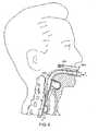
- Figure 5shows a view of device 300 in the fully inserted configuration.
- tab 360is disposed near the patient's upper lip. More specifically, the structure defined by flange 430 and tab 360 extends from the connector portion 400 of the airway tube past the bottom surface of the patient's upper lip towards the patient's nose, and tab 360 is generally proximal to the patient's upper lip. As will be discussed further below, locating tab 360 in this position when device 300 is inserted into a patient advantageously facilitates maintaining device 300 stably in the fully inserted configuration.
- Tab 360advantageously facilitates maintaining device 300 stably in the fully inserted configuration, and, in particular, in maintaining firm contact between the distal end 338 of cuff 334 and the patient's normally closed esophageal sphincter.
- a strip of adhesive tape 500may be attached to tab 360 and the patient's checks.
- Tape 500preferably extends from tab 360 generally towards the patient's ears as shown in Figure 6 .
- the tape 500applies a force to tab 360 generally in the direction of the arrow F shown in Figure 6 .
- Airway tube 310translates this force from tab 360 to the distal end of the device.
- the force applied by tape 500acts to generally pull device 300 into the patient and, in particular, to simultaneously bias (a) the tab towards the patient's mouth and (b) the distal end of the device in the direction indicated by the arrow D in Figure 6 .
- Biasing the distal end of the device in the direction of the arrow Dadvantageously insures that the distal end 338 of cuff 334 remains generally in firm contact with the patient's normally closed esophageal sphincter. Insuring that the distal end of device 300 remains in firm contact with the patient's esophageal sphincter advantageously reduces the likelihood of regurgitated material being aspirated into the patient's lungs during anaesthesia.
- Figures 5 and 6show the position of the tab 360 with respect to the patient's head and upper lip when the device is inserted in a "normal" patient.
- the size and shape of patient's airway passagescan vary somewhat unpredictably such that in some patients the tab may actually contact the upper lip and in other patients the tab may be spaced further away from the upper lip than is shown in Figures 5 and 6 when the device is in the fully inserted configuration. Nonetheless, the tab 360 still facilitates maintaining the device 300 stably in the fully inserted configuration when tape is attached to the tab 360 and the patient's head as shown generally in Figure 6 .
- the distal portion 420 of the connector portion 400 of the airway tubeis oblong.
- the cross section of the integral tube and backplate portion 450is also oblong rather than cylindrical.
- Figure 4Eshows a cross sectional view of the integral tube and backplate portion 450 taken along the line 4E-4E as shown in Figure 4A .
- the integral tube and backplate portionis generally oblong and defines two longitudinal folds 462 that extend along the left and right sides of the airway tube.
- the longitudinal folds 462advantageously help prevent the airway tube from collapsing, or forming a "kink", when the tube is bent so as to insert the device into a patient.
- the patient's natural airway passageis generally oblong rather than cylindrical, and an oblong airway tube fits within the natural airway passage better than a cylindrical tube.
- the tab 360may be used with a variety of laryngeal mask airway devices, it is most advantageously used with devices in which the cross section of the airway tube is oblong (e.g., as generally illustrated in Figure 4E ). Tape applied to the tab 360 applies force along the length of the device, or along a long axis of the devise, as discussed above in connection with Figure 6 and the oblong shape of the airway tube helps prevent the device from twisting about that axis.
- tab 360extends from flange 430 at an angle theta ( ⁇ ). One choice for the angle theta is fifteen degrees. Referring to Figure 4C , tab 360 extends from flange 430 by a height H. One choice for the height H of tab 360 is about fifteen millimeters, Referring to Figure 4A , the line L is parallel to the edges of the proximal portion 410 and the distal portion 420. Flange 430 extends from the proximal and distal portions 410, 420 in directions substantially perpendicular to the line L.
- flange 430extends from distal portion 420 in a direction substantially perpendicular to line L for a distance D, and then angles off, by the angle theta (as shown in Figure 3A ) to define tab 360.
- One choice for the distance Dis five millimeters.
- tab 360extends from the wall of the tube, which defines the tube's internal airway passage, outwardly, or away from the internal passage.
- the tabextends from the tube wall outwardly towards the patient's nose. More generally, if an up-down direction is defined as being along a line extending between the patient's nose and the patient's chin, the tab 360 extends generally in the up-down direction when the device is in the fully inserted configuration.
- tab 360In addition to facilitating holding device 300 stably in the fully inserted configuration, tab 360 also facilitates insertion of device 300 into a patient and also facilitates general manipulation of the device.
- the proximal end of the airway tubeis typically grasped and manipulated as a laryngeal mask airway device is inserted into a patient.
- Lubricantis typically applied to facilitate passing the mask portion through the patient's natural airway.
- the lubricantcan also make the proximal end of the airway tube slippery and difficult to handle.
- Tab 360which extends outwardly from the proximal end of the airway tube, provides an additional surface that may conveniently be grasped during insertion and manipulation of the device. Tab 360 thereby generally facilitates insertion and manipulation of device 300.
- device 300has a single tab 360 that projects generally along the patient's upper lip when the device is in the fully inserted configuration.
- One reason this configuration is convenientis that the patient's upper lip and cheeks are generally immobile with respect to the rest of the patient's head. In contrast, the patient's lower lip and jaw are easily moved with respect to the head and accordingly provide a less stable platform for anchoring the device 300.
- a single tab projecting along the upper lipis a convenient configuration, it will be appreciated that other configurations of tabs may be used.
- devices constructed according to the inventioncan instead include a tab that projects downward along the lower patient's lower lip, or in some other direction.
- devices constructed according to the inventioncan include two tabs, one projecting along the upper lip and another projecting along the lower lip, when the device is in the fully inserted configuration, and adhesive tape may be fixed to either or both of the tabs and to the patient's cheeks or to other parts of the face.
- tabssuch as tab 360
- tabshave been discussed in the context of disposable laryngeal mask airway devices. It will be appreciated that such tabs may also be usefully included according to the invention in non-disposable laryngeal mask airway devices.
- tab 360has been discussed as extending substantially perpendicularly from the distal portion 420 for a distance D and then continuing to extend at an angle theta. It will be appreciated that these are merely preferred choices and that the geometry of the tab can vary considerably. For example, the tab need not extend in a direction substantially perpendicular to a line such as line L, and the tab may instead simply extend in a direction generally transverse, or crosswise, to such a line.
- the tabneed not extend in one direction for a first distance and then continue to extend at the angle theta as shown, and may instead simply be formed, for example, as a single planar piece, However, the tab 360 preferably extends for a distance that is short enough to prevent interference with bodily structures (e.g., short enough to prevent bumping into the nose) and that is long enough to permit easy and reliable attachment of adhesive tape, such that the tape, when applied, reliably biases the tab inwards towards the patient and the tape does not easily slip off of the tab.
- bodily structurese.g., short enough to prevent bumping into the nose
- tab 360differs markedly from flanges used in prior art devices, such as those illustrated in Figures 1A-C .
- Such prior art flangesdid not extend from the airway tube for a sufficient length, or with a suitable geometry, to permit attachment of adhesive tape to the flange and to the patient's head in any fashion that would reliably, and stably, apply a force biasing the device into the patient.
- the tabmay preferably extend at least about fifteen millimeters from the airway tube to permit reliable attachment of adhesive tape to the tab and to the patient's head such that the tape will reliably remain in place and continuously apply a force to the tab so as to bias the tab towards the patient's head.
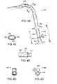
- Figures 7A-7Gshow a variety of tab configurations embraced within the invention. Each of Figures 7A-7G is taken from an orientation similar to that of Figure 4C .
- Figure 7Ashows a configuration similar to that of the tab shown in Figure 4C (i.e., a single tab that projects upwards along the patient's upper lip when the device is in the fully inserted configuration).
- Figure 7Bshows a single tab configuration in which the tab projects downwards towards the patient's chin when the device is in the fully inserted configuration.
- Figure 7Cshows a two tab configuration in which the two tabs project upwards and downwards
- Figure 7Dshows a single upwardly projecting tab in which the sides of the tab are parallel to one another instead of slanted.
- Figure 7Eshows a rounded tab that projects along the upper lip.
- the rounded tabis narrower at the base and wider at the top. If adhesive tape is attached to the base of the tab, the wider portion of the tab near the top can prevent the tape from sliding off of the tab.
- Figure 7Fshows a single tab configuration in which the sides of the tab slant towards a vertex above the end of the tab.
- the tab shown in Figure 7Fhas a straight top edge.
- the top of the tabcan be located at a vertex of the two slanting sides such that the top of the tab is pointed.
- the edges of the tabsmay be curved rather than straight.
- Figure 7Gshows a single tab that projects along the patient's upper lip when the device is in the fully inserted configuration.
- the tabis cylindrical, or rod shaped, rather than flat.
- Figure 8Ashows a perspective view of the anterior side of device 300
- Figures 8B and 8Cshow sectional views of device 300 taken in the direction of arrows 8B-8B and 8C-8C, respectively, as shown in Figure 8A.
- Figures 8A-8Cshow the cuff 334 in detail.
- the cuff 334defines a substantially circular cross section 806, when inflated, and as shown in Figure 8A , the cuff 334 has a generally elliptical profile.
- the shape of the cuff 334is substantially similar to the cuff used in the above-identified device that is commercially marketed as the "Classic", However, unlike the suff used in the Classic, the cuff 334 also includes an epiglottis support flange 810.
- Figure 8Dshows an anterior view of epiglottis support flange 810 separated from the cuff 334.
- the epiglottis support flange 810is preferably formed as an integral part of cuff 334 (e.g., by injection molding), and would not normally exist as a separate component as shown in Figure 8D .
- the unnatural view of epiglottis support flange 810 separated from cuff 334 shown in Figure 8Dconveniently shows the shape of the flange 810
- the epiglottis support flange 810is formed from a thin ring-like sheet of material, and defines an outer perimeter 812, an inner perimeter 814, and a central aperture 340.
- flange 810is generally ring-like, it is not perfectly annular in that neither the inner perimeter 814 nor the outer perimeter 812 are circular. Rather, the inner perimeter 814 and the outer perimeter 812 are generally elliptical and match the generally elliptical profile of cuff 334.
- the flange 810which is not inflatable, is joined to the inflatable portion of cuff 334.
- the inflatable portion of cuff 334defines a circular cross section 806.
- the outer perimeter 812 of flange 810is attached to an inner perimeter 802 of the inflatable portion of cuff 334. More specifically, the outer perimeter 812 of flange 810 is attached to the inflatable portion of cuff 334 at an equatorial location (i.e., half way between the top and bottom of the inflatable portion of the cuff, the orientations top and bottom being with reference to the orientation shown Figures 8B and 8C ).
- flange 810defines a structure that can support the epiglottis when the device is in the fully inserted configuration
- FIG. 9shows one such structure, which consists of a sheet of material 900 that extends across the central aperture defined by the mask, and which itself defines three apertures 910. Such structures have successfully prevented the epiglottis from blocking the airway passage provided by laryngeal mask airway devices, but such structures can also be difficult to fabricate.
- Figure 10shows a cross sectional view of device 300 taken from the same orientation as Figure 8C .
- Figure 10shows the device when inserted into a patient and with the patient's epiglottis 1000 falling into the bowl shape defined by the cuff 334.
- flange 810supports the epiglottis 1000 and restricts the space within which the epiglottis 1000 can fall.
- Flange 810generally prevents the epiglottis from falling so low as to contact the "floor" of the device, the floor being defined by the integral tube and backplate portion 450 of the airway tube 310.
- flange 810prevents the epiglottis 1000 from obstructing the airway passage provided by the device 300, the airway passage being generally indicated by hatching in Figure 10 .
- the airway passage provided by the device near the cuffis oblong (e.g., rather than cylindrical). The oblong shape of the airway passage decreases the likelihood that the epiglottis 1000 could block the passage.
- the flange 810also generally prevents the epiglottis 1000 from spreading out laterally (to the left and right, as shown in Figure 10 , towards the inflated cuff) and blocking the oblong airway passage provided by the device.
- Flange 810also provides support for other anatomical structures, such as the arytenoids, that can fall into the bowl shaped space defined by the device.
- the outer wall of the cufftends to resiliently "spring” back to its original shape whenever any portion of the cuff is depressed, or biased in a particular direction (e.g., by an anatomical structure).
- This tendency of the cuff to resiliently spring back to its original shapeis similar to the fashion in which a child's inflated balloon will return to its original shape when the balloon is squeezed and then released. Since the flange 810 is attached to cuff 334, when cuff 334 is inflated the flange 810 provides a springy, or resilient, support for anatomical structures, such as the epiglottis, that may come into contact with the flange 810.
- the wall of the inflatable portion of the cuff 334 and the flange 810may both be about 0.4 millimeters thick and may both be made of PVC material that is characterized by a durometer of about forty to fifty on the Shore A scale of hardness.
- the entire cuff, including flange 810 and the inflatable portion,are preferably formed simultaneously by injection molding.
- the flange 810preferably does not lie in a single plane. Rather, when the device is oriented as shown in Figure 8B , the inner perimeter 814 is lower than the outer perimeter 812, and the flange is smoothly sloped between its inner and outer perimeters. This configuration helps prevent the flange 810 from presenting a sharp edge to the epiglottis 1000, should the epiglottis fall into the bowl shaped space defined by the device.
- laryngeal mask airway devicesmay be constructed according to the invention that include (a) the tab but not the flange; (b) the flange but not the tab; and (c) both the tab and flange.
- Figure 11shows a sectional side view of another laryngeal mask airway device 700 constructed according to the invention.
- device 700includes airway tube 310, inflatable cuff 334, tab 360, and an epiglottis support flange 810.
- Device 700also includes a rod 710.
- Rod 710extends from a proximal end 712 to a distal end 714.
- Proximal end 712defines a hook shape.
- Rod 710extends past the connector portion 410 of the airway tube 310 such that the hook shaped proximal end 712 is disposed outside of the airway tube 310.
- the distal end 714 of the rod 710is attached or hinged to the epiglottis support flange 810.
- rod 710is attached to the portion of the flange 810 that is closest to the distal end 720 of the device 700.
- Rod 710also defines a visible indicator mark 716 near the proximal end 712.
- Rod 716can be fabricated from a flexible, inelastic material such as nylon.
- Rod 716can be formed as a generally flat strip that is approximately four to five millimeters wide and 0.5 to one millimeters thick.
- rod 710advantageously facilitates (1) insertion of device 700 into a patient; (2) confirmation that device 700 has been properly inserted in the fully inserted configuration; and (3) detection of problems that can occur during insertion of device 700 into a patient.
- Figures 5 and 6show laryngeal mask airway devices that have been placed in the fully inserted configuration. Placing such a device in the fully inserted configuration involves inserting the distal end of the device into the patient's mouth and then advancing the distal end through the patient's natural airway until the distal end is biased against the patient's normally closed esophageal sphincter.
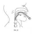
- Figure 12shows a laryngeal mask airway device that has been partially inserted in a patient. As indicated generally in Figure 12 , during insertion, the distal end of the device temporarily curves generally in the direction indicated by the arrow R to enable the device to follow the patient's anatomical airway passage, and in particular to slide past the back of the patient's tongue 800. After temporarily curving in this direction, the device then straightens out again when it is advanced past the back of the tongue so that it can assume the profile generally illustrated in Figures 5 and 6 .
- the laryngeal mask airway deviceis generally simple to insert into a patient (e.g.,. as compared to an endotracheal tube), problems can occur during insertion. For example, instead of lodging against the esophageal sphincter, the distal end of the device sometimes enters the glottic opening such that the device extends partially into the patient's trachea. Also, the distal end of the device can become folded in the direction indicated by the arrow 1, or by the direction indicated by the arrow 2, during insertion and then fail to straighten out again such that the device never reaches the proper fully inserted configuration. Rod 700 helps detect when such undesirable conditions occur, helps prevent such undesirable conditions from occurring, and can sometimes help correct such undesirable conditions.
- the indicator mark 716is adjacent to the proximal end of the connector portion 410 as shown in Figure 11 .
- the indicator mark 716will no longer be adjacent to the proximal end of the connector portion 410 and will instead be displaced outside of the airway tube in the direction indicated by the arrow 4.
- the indicator mark 716will not be adjacent to the proximal end of the connector portion 410 and will instead be withdrawn into the airway tube in the direction indicated by the arrow 3. So, the indicator mark 716 of rod 710 can be used to detect when the device 700 is not in a proper shape for allowing the device to assume the fully inserted configuration. Such use of the indicator mark 716 allows detection of the most common problems associated with insertion of laryngeal mask airway devices.
- the rod 710can also be used to control the shape of device 700.
- the proximal end 712may be grasped and pushed or pulled relative to the airway tube 310 in the directions indicated by arrows 3 and 4. Pulling the proximal end 712 in the direction indicated by arrow 4 causes the distal end 720 of the device to move in the direction indicated by the arrow 1. Similarly, pushing on the proximal end 712 in the direction indicated by arrow 3 causes the distal end 720 of the device to move in the direction indicated by the arrow 2.
- Such motions of the rod 710can facilitate insertion of the device into a patient.
- pulling the rod in the direction indicated by arrow 4can help the distal end of the device to curve around the back of the patient's tongue during insertion.
- pushing on the rod in the direction indicated by arrow 3can help straighten out the device. If it is not possible to correct the shape of the device by pulling or pushing on the rod, the position of the indicator mark 716 will indicate that the device 700 has not been properly inserted and the device can simply be withdrawn from the patient and inserted again.
- tab 360also provides a convenient place for holding airway tube 310 while manipulating the proximal end 712 of rod 710.
- the distal end 714 of rod 710can be attached to the epiglottis support flange 810.
- the distal end of rod 714can alternatively be attached to the airway tube 310 itself.
- Figure 4Ewhich shows a cross section of the integral tube and backplate portion 450, the portion 450 defines a notch 464 and a groove 466.
- Patent Application Serial Nos. 09/544,681 and 10/138,806(Attorney Docket Nos. LMA-3 and LMA-12, notch 464 and groove 466 facilitate insertion of an endotracheal tube through the laryngeal mask airway device. Notch 464 and groove 466 also provide guides for rod 710 that help keep the rod 710 centered within the airway tube and help prevent the rod 710 from being displaced laterally within the airway tube.
- Device 700has been disclosed as including tab 360, epiglottis support flange 810, and rod 710. It will be appreciated that laryngeal mask airway devices may be constructed according to the invention that include the rod with or without either of the tab and flange.
Landscapes
- Health & Medical Sciences (AREA)
- Pulmonology (AREA)
- Animal Behavior & Ethology (AREA)
- General Health & Medical Sciences (AREA)
- Engineering & Computer Science (AREA)
- Anesthesiology (AREA)
- Biomedical Technology (AREA)
- Heart & Thoracic Surgery (AREA)
- Hematology (AREA)
- Life Sciences & Earth Sciences (AREA)
- Veterinary Medicine (AREA)
- Emergency Medicine (AREA)
- Public Health (AREA)
- Otolaryngology (AREA)
- Orthopedics, Nursing, And Contraception (AREA)
- Respiratory Apparatuses And Protective Means (AREA)
- Surgical Instruments (AREA)
- Prostheses (AREA)
- Arc Welding In General (AREA)
- Investigating, Analyzing Materials By Fluorescence Or Luminescence (AREA)
- Magnetically Actuated Valves (AREA)
- Endoscopes (AREA)
Abstract
Description
- The present invention relates to a laryngeal mask airway device, More specifically, the present invention relates to a laryngeal mask airway device having a tab disposed near the device's proximal end for facilitating position control of the device.
- The laryngeal mask airway device is a well known device that is useful for establishing airways in unconscious patients. One popular laryngeal mask airway device has been marketed commercially for many years as the "Classic" by the Laryngeal Mask Company of Cyprus. Such devices are described for example in
U.S. Patent No. 4,509,514 . The Classic is a reusable device and is guaranteed to survive at least forty sterilizations, and in practice these devices may generally be sterilized (and reused) more than forty times before becoming too worn for reuse. In recent years, attempts have been made to develop reduced cost, disposable, laryngeal mask airway devices. Figures 1A, 1B, and 1C show various views of a prior art disposable laryngealmask airway device 100 when the cuff is inflated.Figure 2 shows a partially sectional side view ofdevice 100 when inserted into a patient. Referring toFigure 1A ,device 100 includes anairway tube 110 and amask portion 130.Mask portion 130 includes aflat plate 132 and aninflatable cuff 134.Mask portion 130 extends from aproximal end 136 to adistal end 138.Mask portion 130 is attached to adistal portion 112 ofairway tube 110.Device 100 also includes an inflation line 190 (shown inFigure 1B ) and acheck valve 192 for selectively inflating and deflatingcuff 134,- In operation,
cuff 134 is deflated, and the mask portion is then inserted through the patient's mouth into the patient's pharynx. The device is preferably positioned so thatdistal end 138 ofmask portion 130 rests against the patient's normally closed esophagus and so that the open end 140 (shown inFigure 1C ) ofmask portion 130 is aligned with the entryway of the patient's trachea (i.e., the patient's glottic opening). After the mask portion is so positioned, the cuff is inflated and forms a seal around the patient'sglottic opening 212 and thus establishes a sealed airway extending from aproximal end 114 ofairway tube 110 to the patient's trachea. - For convenience of exposition, the term "fully inserted configuration" shall be used herein to refer to a laryngeal mask airway device that has been inserted into a patient and has the following characteristics: (1) the distal end of the mask portion is pressed against the patient's normally closed esophageal sphincter; (2) the cuff is inflated and forms a seal around the patient's glottic opening; and (3) the airway tube extends from a proximal end located outside the patient's mouth to a distal portion that is coupled to the mask portion, the tube extending through the patient's mouth and the patient's natural upper airway so that the device provides a sealed airway extending from the tube's proximal end to the patient's lungs.
Figure 2 shows a laryngealmask airway device 100 in the fully inserted configuration. As shown, the distal end of themask portion 130 is pressed against the patient'sesophageal sphincter 210. Also, the open end of the mask portion forms a seal around theglottic opening 212 thereby enabling thedevice 100 to provide fluid communication with thetrachea 214.- Although prior art disposable laryngeal mask airway devices have performed well, there remains a need for providing improved devices, In particular, there remains a need for providing a disposable laryngeal mask airway device that more reliably remains stably in the fully inserted configuration once the device has been inserted into a patient.
- According to the invention, there is provided a laryngeal mask airway device, comprising an inflatable cuff, the cuff defining a central opening at least when inflated, the caff being insertable through a mouth of a patient to an inserted location within the patient, the cuff surrounding a glottic opening of the patient when inflated and at the inserted location, an airway tube extending from a proximal end to a distal end, the airway tube defining an internal passage, a sealed airway passage extending from the proximal end of the tube through the internal passage to the glottic opening when the cuff is inflated and at the inserted location, and a tab disposed on the airway tube near the proximal end of the airway tube such that the tab is disposed outside of the mouth of the patient when the cuff is at the inserted location.
- The device includes a tab disposed near the proximal end of the airway tube, When the device is inserted into a patient, the tab is disposed near the patient's upper lip. The tab is conveniently located so that adhesive tape may be attached to the tab and the patient's cheeks. The tape applies a force that biases the device generally into the patient and, in particular, biases the distal end of the device against the patients esophageal sphincter. This allows the device to remain more stably in the fully inserted configuration and reduces the likelihood that regurgitated material will be aspirated- into the patient's lungs. The device may also include a flange in the inflatable cuff for supporting the epiglottis and preventing the epiglottis from blocking the airway passage provided by the device.
- Still other objects and advantages of the present invention will become readily apparent to those skilled in the art from the following detailed description wherein several embodiments are shown and described, simply by way of illustration of the invention,
- For a fuller understanding of the nature and objects of the present invention, reference should be made to the following detailed description taken in connection with the accompanying drawings in which the same reference numerals are used to indicate the same or similar parts wherein:
Figure 1A shows a side view of a prior art disposable laryngeal mask airway device when the cuff is inflated.Figure 1B shows a perspective view of the posterior side of the prior art device shown inFigure 1A .Figure 1C shows a perspective view of the anterior side of the prior art device shown inFigure 1A .Figure 2 shows a partially sectional side view of the device shown inFigures 1A-1C when the device is in the fully inserted configuration.Figure 3A shows a side view of a disposable laryngeal mask airway device constructed according to the invention, when the cuff is inflated.Figure 3B shows a perspective view of the posterior side of the device shown inFigure 3A .Figure 4A shows an exploded side view of the airway tube of the device shown inFigures 3A and3B .Figure 4B shows a top view of the connector portion of the airway tube taken in the direction ofarrow 4B-4B as shown inFigure 4A .Figures 4C and 4D show end views of the connector portion of the airway tube taken in the direction ofarrows 4C-4C and 4D-4D, respectively, as shown inFigure 4A .Figure 4E shows a cross sectional view of the integral tube and backplate portion taken along theline 4E-4E as shown inFigure 4A .Figure 5 shows a partially sectional side view of a disposable laryngeal mask airway device constructed according to the invention when in the fully inserted configuration.Figure 6 shows a partially sectional side view of a disposable laryngeal mask airway device constructed according to the invention when adhesive tape has been applied to the tab and to the patient's cheeks to help maintain the device stably in the fully inserted configuration,Figures 7A-7G show alternative configurations of tabs constructed according to the invention.Figure 8A shows a perspective view of the anterior side of the device shown inFigure 3A .Figures 8B and 8C show sectional views of the device taken along thelines 8B-8B and 8C-8C, as shown inFigure 8A .Figure 8D shows a view of the epiglottis support flange contained within the cuff shown inFigure 8A .Figure 9 shows one type of support for preventing the epiglottis from occluding the airway passage provided by a laryngeal mask airway device.Figure 10 shows a sectional view of the device taken from the same vantage asFigure 8C when the device is inserted into a patient and the patient's epiglottis is falling into the bowl shaped space defined by the device,Figure 11 shows a sectional view of another laryngeal mask airway device constructed according to the invention.Figure 12 shows a laryngeal mask airway device that has been partially inserted into a patientFigures 3A and3B show side and perspective views, respectively, of an improved disposable laryngealmask airway device 300 constructed according to the invention.Device 300 includes anairway tube 310 and aninflatable cuff 334. Thecuff 334 extends from aproximal end 336 to adistal end 338.Device 300 includes an inflation line 390, coupled toproximal end 336 ofcuff 334, and acheck valve 392 for selectively minting and deflatingcuff 334.Device 300 also includes atab 360, which is integrally attached to airwaytube 310. As will be discussed further below,tab 360 advantageously facilitates maintainingdevice 300 stably in the fully inserted configuration,Figure 4A shows an exploded side view ofairway rube 310 prior to attachment ofcuff 334. As shown,airway tube 310 includes aconnector portion 400 and an integral tube andbackplate portion 450.Figures 4B, 4C and 4D show views ofconnector portion 400 taken in the direction ofarrows 4B-4B, 4C-4C, and 4D-4D, respectively, as shown inFigure 4A .Connector portion 400 includes aproximal portion 410, adistal portion 420, and aflange 430 located between the proximal anddistal portions Tab 360 is formed as an integral part offlange 430.Proximal portion 410 is cylindrical and is configured to couple to standard medical ventilating, or anaesthetic devices.Distal portion 420 is oblong and is configured for telescopic insertion into aproximal end 452 of integral tube andbackplate portion 450. Airwaytube 310 is assembled by telescopically insertingdistal portion 420 into theproximal end 452 of integral tube andbackplate portion 450 untilflange 430 contactsproximal end 452 as shown inFigure 3A .Connector portion 400 is made of a rigid plastic or polycarbonate material.Connector portion 400 can be made, for example, by injection molding.Connector portion 400 is preferably a single monolithic piece that definesproximal portion 410,distal portion 420,flange 430, andtab 360.Flange 430 andtab 360 are preferably rigid, and are preferably rigidly fixed relative to the rest ofconnector portion 400. Integral tube andbackplate portion 450 is also made of a plastic material such as PVC and is softer thanconnector portion 400. Integral tube andbackplate portion 450 is characterized by a durometer of about 90 on the Shore A scale of hardness. Integral tube andbackplate portion 450 may also be made by injection molding and is preferably a single monolithic piece.Figure 5 shows a view ofdevice 300 in the fully inserted configuration. As shown, whendevice 300 is in the fully inserted configuration,tab 360 is disposed near the patient's upper lip. More specifically, the structure defined byflange 430 andtab 360 extends from theconnector portion 400 of the airway tube past the bottom surface of the patient's upper lip towards the patient's nose, andtab 360 is generally proximal to the patient's upper lip. As will be discussed further below, locatingtab 360 in this position whendevice 300 is inserted into a patient advantageously facilitates maintainingdevice 300 stably in the fully inserted configuration.- One problem with prior art disposable laryngeal mask airway devices is that they sometimes do not remain stably in the fully inserted configuration. In particular, in prior art devices it is difficult to insure that the distal tip of the device remains pressed against the patient's normally closed esophageal sphincter.
Tab 360 advantageously facilitates maintainingdevice 300 stably in the fully inserted configuration, and, in particular, in maintaining firm contact between thedistal end 338 ofcuff 334 and the patient's normally closed esophageal sphincter. - As shown in
Figure 6 , oncedevice 300 is inserted into a patient, a strip ofadhesive tape 500 may be attached totab 360 and the patient's checks.Tape 500 preferably extends fromtab 360 generally towards the patient's ears as shown inFigure 6 . Oncetape 500 is attached totab 360 and the patient's cheeks, thetape 500 applies a force totab 360 generally in the direction of the arrow F shown inFigure 6 .Airway tube 310 translates this force fromtab 360 to the distal end of the device. The force applied bytape 500 acts to generally pulldevice 300 into the patient and, in particular, to simultaneously bias (a) the tab towards the patient's mouth and (b) the distal end of the device in the direction indicated by the arrow D inFigure 6 . Biasing the distal end of the device in the direction of the arrow D advantageously insures that thedistal end 338 ofcuff 334 remains generally in firm contact with the patient's normally closed esophageal sphincter. Insuring that the distal end ofdevice 300 remains in firm contact with the patient's esophageal sphincter advantageously reduces the likelihood of regurgitated material being aspirated into the patient's lungs during anaesthesia. Figures 5 and6 show the position of thetab 360 with respect to the patient's head and upper lip when the device is inserted in a "normal" patient. However, the size and shape of patient's airway passages can vary somewhat unpredictably such that in some patients the tab may actually contact the upper lip and in other patients the tab may be spaced further away from the upper lip than is shown inFigures 5 and6 when the device is in the fully inserted configuration. Nonetheless, thetab 360 still facilitates maintaining thedevice 300 stably in the fully inserted configuration when tape is attached to thetab 360 and the patient's head as shown generally inFigure 6 .- As noted above, and as shown in
Figures 4A, 4B, and 4D , thedistal portion 420 of theconnector portion 400 of the airway tube is oblong. The cross section of the integral tube andbackplate portion 450 is also oblong rather than cylindrical.Figure 4E shows a cross sectional view of the integral tube andbackplate portion 450 taken along theline 4E-4E as shown inFigure 4A . As shown inFigure 4E , the integral tube and backplate portion is generally oblong and defines twolongitudinal folds 462 that extend along the left and right sides of the airway tube. Thelongitudinal folds 462 advantageously help prevent the airway tube from collapsing, or forming a "kink", when the tube is bent so as to insert the device into a patient. Also, the patient's natural airway passage is generally oblong rather than cylindrical, and an oblong airway tube fits within the natural airway passage better than a cylindrical tube. Once an oblong airway tube has been positioned within a patient, the anatomical structures that define the patient's nature airway passage tend to prevent the tube from twisting, or rotating, in the direction generally indicated by the arrow R-R shown inFigure 4E . In contrast, a device with a cylindrical airway tube rotates within the patient, in the direction indicated by the arrow R-R, much more easily. - Although the
tab 360 may be used with a variety of laryngeal mask airway devices, it is most advantageously used with devices in which the cross section of the airway tube is oblong (e.g., as generally illustrated inFigure 4E ). Tape applied to thetab 360 applies force along the length of the device, or along a long axis of the devise, as discussed above in connection withFigure 6 and the oblong shape of the airway tube helps prevent the device from twisting about that axis. - Referring back to
Figure 3A ,tab 360 extends fromflange 430 at an angle theta (θ). One choice for the angle theta is fifteen degrees. Referring toFigure 4C ,tab 360 extends fromflange 430 by a height H. One choice for the height H oftab 360 is about fifteen millimeters, Referring toFigure 4A , the line L is parallel to the edges of theproximal portion 410 and thedistal portion 420.Flange 430 extends from the proximal anddistal portions flange 430 extends fromdistal portion 420 in a direction substantially perpendicular to line L for a distance D, and then angles off, by the angle theta (as shown inFigure 3A ) to definetab 360. One choice for the distance D is five millimeters. - Another way to describe the orientation of
tab 360 with respect to the airway tube is that the tab extends from the wall of the tube, which defines the tube's internal airway passage, outwardly, or away from the internal passage. When thedevice 300 is in the fully inserted configuration, the tab extends from the tube wall outwardly towards the patient's nose. More generally, if an up-down direction is defined as being along a line extending between the patient's nose and the patient's chin, thetab 360 extends generally in the up-down direction when the device is in the fully inserted configuration. - In addition to facilitating
holding device 300 stably in the fully inserted configuration,tab 360 also facilitates insertion ofdevice 300 into a patient and also facilitates general manipulation of the device. The proximal end of the airway tube is typically grasped and manipulated as a laryngeal mask airway device is inserted into a patient. Lubricant is typically applied to facilitate passing the mask portion through the patient's natural airway. However, the lubricant can also make the proximal end of the airway tube slippery and difficult to handle.Tab 360, which extends outwardly from the proximal end of the airway tube, provides an additional surface that may conveniently be grasped during insertion and manipulation of the device.Tab 360 thereby generally facilitates insertion and manipulation ofdevice 300. - As discussed above,
device 300 has asingle tab 360 that projects generally along the patient's upper lip when the device is in the fully inserted configuration. One reason this configuration is convenient is that the patient's upper lip and cheeks are generally immobile with respect to the rest of the patient's head. In contrast, the patient's lower lip and jaw are easily moved with respect to the head and accordingly provide a less stable platform for anchoring thedevice 300. However, although a single tab projecting along the upper lip is a convenient configuration, it will be appreciated that other configurations of tabs may be used. For example, devices constructed according to the invention can instead include a tab that projects downward along the lower patient's lower lip, or in some other direction. Alternatively, devices constructed according to the invention can include two tabs, one projecting along the upper lip and another projecting along the lower lip, when the device is in the fully inserted configuration, and adhesive tape may be fixed to either or both of the tabs and to the patient's cheeks or to other parts of the face. - Also, provision of tabs, such as
tab 360, have been discussed in the context of disposable laryngeal mask airway devices. It will be appreciated that such tabs may also be usefully included according to the invention in non-disposable laryngeal mask airway devices. - Also,
tab 360 has been discussed as extending substantially perpendicularly from thedistal portion 420 for a distance D and then continuing to extend at an angle theta. It will be appreciated that these are merely preferred choices and that the geometry of the tab can vary considerably. For example, the tab need not extend in a direction substantially perpendicular to a line such as line L, and the tab may instead simply extend in a direction generally transverse, or crosswise, to such a line. Also, the tab need not extend in one direction for a first distance and then continue to extend at the angle theta as shown, and may instead simply be formed, for example, as a single planar piece, However, thetab 360 preferably extends for a distance that is short enough to prevent interference with bodily structures (e.g., short enough to prevent bumping into the nose) and that is long enough to permit easy and reliable attachment of adhesive tape, such that the tape, when applied, reliably biases the tab inwards towards the patient and the tape does not easily slip off of the tab. - It will be appreciated that
tab 360 differs markedly from flanges used in prior art devices, such as those illustrated inFigures 1A-C . Such prior art flanges did not extend from the airway tube for a sufficient length, or with a suitable geometry, to permit attachment of adhesive tape to the flange and to the patient's head in any fashion that would reliably, and stably, apply a force biasing the device into the patient. The tab may preferably extend at least about fifteen millimeters from the airway tube to permit reliable attachment of adhesive tape to the tab and to the patient's head such that the tape will reliably remain in place and continuously apply a force to the tab so as to bias the tab towards the patient's head. Figures 7A-7G show a variety of tab configurations embraced within the invention. Each ofFigures 7A-7G is taken from an orientation similar to that ofFigure 4C .Figure 7A shows a configuration similar to that of the tab shown inFigure 4C (i.e., a single tab that projects upwards along the patient's upper lip when the device is in the fully inserted configuration).Figure 7B shows a single tab configuration in which the tab projects downwards towards the patient's chin when the device is in the fully inserted configuration.Figure 7C shows a two tab configuration in which the two tabs project upwards and downwards,Figure 7D shows a single upwardly projecting tab in which the sides of the tab are parallel to one another instead of slanted.Figure 7E shows a rounded tab that projects along the upper lip. The rounded tab is narrower at the base and wider at the top. If adhesive tape is attached to the base of the tab, the wider portion of the tab near the top can prevent the tape from sliding off of the tab.Figure 7F shows a single tab configuration in which the sides of the tab slant towards a vertex above the end of the tab. The tab shown inFigure 7F has a straight top edge. Alternatively, the top of the tab can be located at a vertex of the two slanting sides such that the top of the tab is pointed. As yet another alternative to any of the configurations shown inFigures 7A-7F , the edges of the tabs may be curved rather than straight.Figure 7G shows a single tab that projects along the patient's upper lip when the device is in the fully inserted configuration. InFigure 7G , the tab is cylindrical, or rod shaped, rather than flat.Figure 8A shows a perspective view of the anterior side ofdevice 300,Figures 8B and 8C show sectional views ofdevice 300 taken in the direction ofarrows 8B-8B and 8C-8C, respectively, as shown inFigure 8A. Figures 8A-8C show thecuff 334 in detail. As shown inFigures 8B and 8C , thecuff 334 defines a substantiallycircular cross section 806, when inflated, and as shown inFigure 8A , thecuff 334 has a generally elliptical profile. The shape of thecuff 334 is substantially similar to the cuff used in the above-identified device that is commercially marketed as the "Classic", However, unlike the suff used in the Classic, thecuff 334 also includes anepiglottis support flange 810.Figure 8D shows an anterior view ofepiglottis support flange 810 separated from thecuff 334. Theepiglottis support flange 810 is preferably formed as an integral part of cuff 334 (e.g., by injection molding), and would not normally exist as a separate component as shown inFigure 8D . However, the unnatural view ofepiglottis support flange 810 separated fromcuff 334 shown inFigure 8D conveniently shows the shape of theflange 810, Theepiglottis support flange 810 is formed from a thin ring-like sheet of material, and defines anouter perimeter 812, aninner perimeter 814, and acentral aperture 340. Whileflange 810 is generally ring-like, it is not perfectly annular in that neither theinner perimeter 814 nor theouter perimeter 812 are circular. Rather, theinner perimeter 814 and theouter perimeter 812 are generally elliptical and match the generally elliptical profile ofcuff 334. Theflange 810, which is not inflatable, is joined to the inflatable portion ofcuff 334.- As shown in
Figures 8B and 8C , the inflatable portion ofcuff 334 defines acircular cross section 806. Theouter perimeter 812 offlange 810 is attached to aninner perimeter 802 of the inflatable portion ofcuff 334. More specifically, theouter perimeter 812 offlange 810 is attached to the inflatable portion ofcuff 334 at an equatorial location (i.e., half way between the top and bottom of the inflatable portion of the cuff, the orientations top and bottom being with reference to the orientation shownFigures 8B and 8C ). - When
cuff 334 is deflated, the presence offlange 810 does not add substantially to the thickness of the device. Whencuff 334 is inflated,flange 810 defines a structure that can support the epiglottis when the device is in the fully inserted configuration, - As is known, when a patient is lying in a supine position (i.e., on their back facing upwards), and when a laryngeal mask airway device is inserted in the patient, the patient's epiglottis may fall into the bowl shaped space defined (at least in part) by the inflated cuff and obstruct the airway provided by the device. Various structures have been proposed for preventing the epiglottis from so obstructing the airway.
Figure 9 shows one such structure, which consists of a sheet ofmaterial 900 that extends across the central aperture defined by the mask, and which itself defines threeapertures 910. Such structures have successfully prevented the epiglottis from blocking the airway passage provided by laryngeal mask airway devices, but such structures can also be difficult to fabricate. Figure 10 shows a cross sectional view ofdevice 300 taken from the same orientation asFigure 8C . However,Figure 10 shows the device when inserted into a patient and with the patient'sepiglottis 1000 falling into the bowl shape defined by thecuff 334. As shown,flange 810 supports theepiglottis 1000 and restricts the space within which theepiglottis 1000 can fall.Flange 810 generally prevents the epiglottis from falling so low as to contact the "floor" of the device, the floor being defined by the integral tube andbackplate portion 450 of theairway tube 310. Most importantly,flange 810 prevents theepiglottis 1000 from obstructing the airway passage provided by thedevice 300, the airway passage being generally indicated by hatching inFigure 10 . Due to the oblong shape of the integral tube andbackplate portion 450 of the airway tube 3 10, the airway passage provided by the device near the cuff is oblong (e.g., rather than cylindrical). The oblong shape of the airway passage decreases the likelihood that theepiglottis 1000 could block the passage. However, in addition to generally preventing theepiglottis 1000 from falling to the "floor" of the device and contacting the integral tube and backplate portion, theflange 810 also generally prevents theepiglottis 1000 from spreading out laterally (to the left and right, as shown inFigure 10 , towards the inflated cuff) and blocking the oblong airway passage provided by the device.Flange 810 also provides support for other anatomical structures, such as the arytenoids, that can fall into the bowl shaped space defined by the device.- When
cuff 334 is inflated, the outer wall of the cuff tends to resiliently "spring" back to its original shape whenever any portion of the cuff is depressed, or biased in a particular direction (e.g., by an anatomical structure). This tendency of the cuff to resiliently spring back to its original shape is similar to the fashion in which a child's inflated balloon will return to its original shape when the balloon is squeezed and then released. Since theflange 810 is attached tocuff 334, whencuff 334 is inflated theflange 810 provides a springy, or resilient, support for anatomical structures, such as the epiglottis, that may come into contact with theflange 810. - The wall of the inflatable portion of the
cuff 334 and theflange 810 may both be about 0.4 millimeters thick and may both be made of PVC material that is characterized by a durometer of about forty to fifty on the Shore A scale of hardness. The entire cuff, includingflange 810 and the inflatable portion, are preferably formed simultaneously by injection molding. - As shown best in
Figures 8B, 8C, and 10 , theflange 810 preferably does not lie in a single plane. Rather, when the device is oriented as shown inFigure 8B , theinner perimeter 814 is lower than theouter perimeter 812, and the flange is smoothly sloped between its inner and outer perimeters. This configuration helps prevent theflange 810 from presenting a sharp edge to theepiglottis 1000, should the epiglottis fall into the bowl shaped space defined by the device. Device 300 has been disclosed as includingtab 360 andepiglottis support flange 810. It will be appreciated that laryngeal mask airway devices may be constructed according to the invention that include (a) the tab but not the flange; (b) the flange but not the tab; and (c) both the tab and flange.Figure 11 shows a sectional side view of another laryngeal mask airway device 700 constructed according to the invention. Like previously discussed devices constructed according to the invention, device 700 includesairway tube 310,inflatable cuff 334,tab 360, and anepiglottis support flange 810. Device 700 also includes arod 710.Rod 710 extends from aproximal end 712 to adistal end 714.Proximal end 712 defines a hook shape.Rod 710 extends past theconnector portion 410 of theairway tube 310 such that the hook shapedproximal end 712 is disposed outside of theairway tube 310. Thedistal end 714 of therod 710 is attached or hinged to theepiglottis support flange 810. As illustrated, thedistal end 714 ofrod 710 is attached to the portion of theflange 810 that is closest to thedistal end 720 of the device 700.Rod 710 also defines avisible indicator mark 716 near theproximal end 712.Rod 716 can be fabricated from a flexible, inelastic material such as nylon.Rod 716 can be formed as a generally flat strip that is approximately four to five millimeters wide and 0.5 to one millimeters thick. As will be discussed below,rod 710 advantageously facilitates (1) insertion of device 700 into a patient; (2) confirmation that device 700 has been properly inserted in the fully inserted configuration; and (3) detection of problems that can occur during insertion of device 700 into a patient.- As discussed above,
Figures 5 and6 show laryngeal mask airway devices that have been placed in the fully inserted configuration. Placing such a device in the fully inserted configuration involves inserting the distal end of the device into the patient's mouth and then advancing the distal end through the patient's natural airway until the distal end is biased against the patient's normally closed esophageal sphincter.Figure 12 shows a laryngeal mask airway device that has been partially inserted in a patient. As indicated generally inFigure 12 , during insertion, the distal end of the device temporarily curves generally in the direction indicated by the arrow R to enable the device to follow the patient's anatomical airway passage, and in particular to slide past the back of the patient'stongue 800. After temporarily curving in this direction, the device then straightens out again when it is advanced past the back of the tongue so that it can assume the profile generally illustrated inFigures 5 and6 . - Although the laryngeal mask airway device is generally simple to insert into a patient (e.g.,. as compared to an endotracheal tube), problems can occur during insertion. For example, instead of lodging against the esophageal sphincter, the distal end of the device sometimes enters the glottic opening such that the device extends partially into the patient's trachea. Also, the distal end of the device can become folded in the direction indicated by the arrow 1, or by the direction indicated by the arrow 2, during insertion and then fail to straighten out again such that the device never reaches the proper fully inserted configuration. Rod 700 helps detect when such undesirable conditions occur, helps prevent such undesirable conditions from occurring, and can sometimes help correct such undesirable conditions.
- When device 700 is in the proper shape for allowing the device to assume the fully inserted configuration, the
indicator mark 716 is adjacent to the proximal end of theconnector portion 410 as shown inFigure 11 . However, if the device is bent or curved such that thedistal end 720 of the device is displaced in the direction indicated by the arrow 1, theindicator mark 716 will no longer be adjacent to the proximal end of theconnector portion 410 and will instead be displaced outside of the airway tube in the direction indicated by the arrow 4. Similarly, if the device is bent or curved such that thedistal end 720 of the device is displaced in the direction indicated by the arrow 2, theindicator mark 716 will not be adjacent to the proximal end of theconnector portion 410 and will instead be withdrawn into the airway tube in the direction indicated by the arrow 3. So, theindicator mark 716 ofrod 710 can be used to detect when the device 700 is not in a proper shape for allowing the device to assume the fully inserted configuration. Such use of theindicator mark 716 allows detection of the most common problems associated with insertion of laryngeal mask airway devices. - In addition to using the
rod 710 to detect the condition, or shape, of device 700, therod 710 can also be used to control the shape of device 700. Theproximal end 712 may be grasped and pushed or pulled relative to theairway tube 310 in the directions indicated by arrows 3 and 4. Pulling theproximal end 712 in the direction indicated by arrow 4 causes thedistal end 720 of the device to move in the direction indicated by the arrow 1. Similarly, pushing on theproximal end 712 in the direction indicated by arrow 3 causes thedistal end 720 of the device to move in the direction indicated by the arrow 2. Such motions of therod 710 can facilitate insertion of the device into a patient. For example, pulling the rod in the direction indicated by arrow 4 can help the distal end of the device to curve around the back of the patient's tongue during insertion. Similarly, pushing on the rod in the direction indicated by arrow 3 can help straighten out the device. If it is not possible to correct the shape of the device by pulling or pushing on the rod, the position of theindicator mark 716 will indicate that the device 700 has not been properly inserted and the device can simply be withdrawn from the patient and inserted again. - In addition to the other advantageous features of
tab 360 which have been discussed above,tab 360 also provides a convenient place for holdingairway tube 310 while manipulating theproximal end 712 ofrod 710. As discussed above, thedistal end 714 ofrod 710 can be attached to theepiglottis support flange 810. However, the distal end ofrod 714 can alternatively be attached to theairway tube 310 itself. In such embodiments, it is generally advantageous to attach the distal end of therod 714 to the distal most portion of theairway tube 310. Referring back toFigure 4E , which shows a cross section of the integral tube andbackplate portion 450, theportion 450 defines anotch 464 and agroove 466. As discussed in the above-identified copendingU.S. Patent Application Serial Nos. 09/544,681 and10/138,806 notch 464 and groove 466 facilitate insertion of an endotracheal tube through the laryngeal mask airway device.Notch 464 and groove 466 also provide guides forrod 710 that help keep therod 710 centered within the airway tube and help prevent therod 710 from being displaced laterally within the airway tube. - Device 700 has been disclosed as including
tab 360,epiglottis support flange 810, androd 710. It will be appreciated that laryngeal mask airway devices may be constructed according to the invention that include the rod with or without either of the tab and flange. - Since certain changes may be made in the above apparatus without departing from the scope of the invention herein involved, it is intended that all matter contained in the above description or shown in the accompanying drawing shall be interpreted in an illustrative and not a limiting sense.
Claims (16)
- A laryngeal mask airway device, comprising:an airway tube extending from a proximal end to a distal end, the airway tube defining an internal passage,an inflatable cuff, the cuff defining a central opening at least when inflated, the cuff being disposed near the distal end of the airway tube, the cuff being insertable through a mouth of a patient to an inserted location within the patient, the cuff surrounding a glottic opening of the patient when inflated and at the inserted location,a sealed airway passage extending from the proximal end of the tube through the internal passage to the glottic opening when the cuff is inflated and at the inserted location, the cuff defining an inner perimeter that bounds the central opening, andan epiglottis support flange, the flange defining an outer perimeter and an inner perimeter, the flange comprising a solid sheet of material extending between the outer and inner perimeters of the flange, the outer perimeter of the flange being fixed to the inner perimeter of the cuff, the inner perimeter of the flange defining a single opening, the single opening being smaller than the central opening.
- A device according to claim 1, the epiglottis support flange being part of the cuff.
- A device according to claim 1 or 2, the cuff defining an inner perimeter that bounds the central opening, the epiglottis support flange defining an outer perimeter and an inner perimeter, the outer perimeter of the epiglottis support flange being fixed to the inner perimeter of the cuff, the inner perimeter of the epiglottis support flange defining a second opening, the second opening being smaller than the central opening.
- A device according to claim 3, wherein the epiglottis support flange comprises a solid sheet of material extending between the outer and inner perimeters of the epiglottis support flange.
- A device according to any preceding claim, a cross section of the airway tube being oblong.
- A device according to any preceding claim, the device further comprising means to detect the condition or shape of the device and to control the shape of the device, said means allowing the device to assume the fully inserted condition.
- A device according to claim 6, wherein the means to detect the condition or shape of the device and to control the shape of the device comprises a rod that extends from a proximal end to a distal end, the proximal end defining a hook shape, which hook shaped proximal end is disposed outside of the airway tube, and the rod defining a visible indicator mark near the proximal end.
- A device according to claim 7, wherein the rod is fabricated from a flexible, inelastic material such as nylon.
- A device according to claim 7 or 8, wherein the distal end of the rod is attached to the airway tube or the distal end of the rod is attached or hinged to the epiglottis support flange.
- A device according to any of claims 7 to 9, wherein the device comprises an integral tube and backplate portion, and the portion defines a notch and a groove.
- A device according to any preceding claim, wherein the device further comprises a tab disposed on the airway tube near the proximal end of the airway tube such that the tab is disposed outside of the mouth of the patient when the cuff is at the inserted location.
- A device according to claim 11, the tab being disposed in use, near an upper lip of the patient when the cuff is at the inserted location, such that the tab extends from the airway tube towards a nose of the patient when the cuff is at the inserted location.
- A device according to claim 11 or 12, the tab including a first portion and a second portion, the first portion of the tab extending outwardly from the airway tube, the second portion extending from the first portion at an angle with respect to the first portion, the angle being different than one hundred-eighty degrees.
- A device according to any preceding claim, the airway tube including a connector portion and a second portion, the connector portion including a proximal portion, a distal portion, and a flange, the flange being disposed between the proximal and distal portions, the distal portion being inserted into a proximal end of the second portion, the proximal portion being cylindrical, and the flange defining the tab.
- A device according to any of claims 11 to 14, the tab being configured to permit application of adhesive tape to the tab and a face of the patient such that the tape, when applied, biases the tab towards the mouth of the patient.
- A device according to any of claims 11 to 15, the tab being substantially rigid.
Applications Claiming Priority (2)
| Application Number | Priority Date | Filing Date | Title |
|---|---|---|---|
| US10/657,418US7134431B2 (en) | 2003-09-08 | 2003-09-08 | Laryngeal mask airway device with position controlling tab |
| EP04764731AEP1663364B1 (en) | 2003-09-08 | 2004-09-01 | Laryngeal mask airway device with position controlling tab |
Related Parent Applications (2)
| Application Number | Title | Priority Date | Filing Date |
|---|---|---|---|
| EP04764731.8Division | 2004-09-01 | ||
| EP04764731ADivisionEP1663364B1 (en) | 2003-09-08 | 2004-09-01 | Laryngeal mask airway device with position controlling tab |
Publications (2)
| Publication Number | Publication Date |
|---|---|
| EP2165727A2true EP2165727A2 (en) | 2010-03-24 |
| EP2165727A3 EP2165727A3 (en) | 2014-05-21 |
Family
ID=34226544
Family Applications (3)
| Application Number | Title | Priority Date | Filing Date |
|---|---|---|---|
| EP10150122.9AWithdrawnEP2165727A3 (en) | 2003-09-08 | 2004-09-01 | Laryngeal Mask Airway Device with Position Controlling Tab |
| EP04764731AExpired - LifetimeEP1663364B1 (en) | 2003-09-08 | 2004-09-01 | Laryngeal mask airway device with position controlling tab |
| EP10150123.7AWithdrawnEP2165728A3 (en) | 2003-09-08 | 2004-09-01 | Laryngeal Mask Airway Device with Position Controlling Tab |
Family Applications After (2)
| Application Number | Title | Priority Date | Filing Date |
|---|---|---|---|
| EP04764731AExpired - LifetimeEP1663364B1 (en) | 2003-09-08 | 2004-09-01 | Laryngeal mask airway device with position controlling tab |
| EP10150123.7AWithdrawnEP2165728A3 (en) | 2003-09-08 | 2004-09-01 | Laryngeal Mask Airway Device with Position Controlling Tab |
Country Status (18)
| Country | Link |
|---|---|
| US (1) | US7134431B2 (en) |
| EP (3) | EP2165727A3 (en) |
| JP (3) | JP4847865B2 (en) |
| KR (1) | KR20060121861A (en) |
| CN (2) | CN101822861A (en) |
| AT (1) | ATE464086T1 (en) |
| AU (2) | AU2004269901B2 (en) |
| BR (1) | BRPI0414202B1 (en) |
| CA (1) | CA2537957C (en) |
| DE (1) | DE602004026605D1 (en) |
| ES (1) | ES2356349T3 (en) |
| IL (1) | IL174083A0 (en) |
| MX (1) | MXPA06002628A (en) |
| PL (1) | PL379562A1 (en) |
| RU (1) | RU2379063C2 (en) |
| TW (1) | TW200520803A (en) |
| WO (1) | WO2005023351A1 (en) |
| ZA (1) | ZA200602658B (en) |
Cited By (1)
| Publication number | Priority date | Publication date | Assignee | Title |
|---|---|---|---|---|
| WO2017220226A2 (en) | 2016-03-31 | 2017-12-28 | Teleflex Life Sciences | Fixation device |
Families Citing this family (63)
| Publication number | Priority date | Publication date | Assignee | Title |
|---|---|---|---|---|
| US5878745A (en) | 1996-03-01 | 1999-03-09 | Brain; Archibald I.J. | Gastro-laryngeal mask |
| US7357845B2 (en)* | 1997-04-10 | 2008-04-15 | Cookgas, L.L.C. | Methods of making laryngeal masks |
| US8631796B2 (en) | 1997-04-10 | 2014-01-21 | Cookgas, L.L.C. | Laryngeal mask |
| US7331346B2 (en) | 1997-12-24 | 2008-02-19 | Indian Ocean Medical, Inc. | Monitoring and control for a laryngeal mask airway device |
| USD518572S1 (en)* | 2002-08-14 | 2006-04-04 | Muhammed Aslam Nasir | Laryngeal mask airway device |
| GB0218868D0 (en) | 2002-08-14 | 2002-09-25 | Nasir Muhammed A | Improved airway management device |
| WO2005016427A2 (en)* | 2003-08-14 | 2005-02-24 | Muhammed Aslam Nasir | Improved airway device |
| US7134431B2 (en)* | 2003-09-08 | 2006-11-14 | Indian Ocean Medical Inc. | Laryngeal mask airway device with position controlling tab |
| US7096868B2 (en)* | 2004-03-09 | 2006-08-29 | Nellcor Puritan Bennett Incorporated | Laryngeal airway device |
| USD518890S1 (en)* | 2004-06-24 | 2006-04-11 | Muhammed Aslam Nasir | Laryngeal mask airway device |
| GB0510951D0 (en) | 2005-05-27 | 2005-07-06 | Laryngeal Mask Company The Ltd | Laryngeal mask airway device |
| US20070023051A1 (en)* | 2005-07-30 | 2007-02-01 | Cook Daniel J | Inflatable airways with pressure monitoring devices |
| US7735489B2 (en)* | 2006-01-13 | 2010-06-15 | Olympus Medical Systems Corp. | Endotracheal tube, device for use in medical procedure through natural opening and medical procedure through natural opening |
| USD615188S1 (en) | 2006-02-14 | 2010-05-04 | Intersurgical Uab | Airway device |
| US7900632B2 (en) | 2006-08-18 | 2011-03-08 | Cookgas, L.L.C. | Laryngeal mask with esophageal blocker and bite block |
| US7784464B2 (en) | 2006-09-15 | 2010-08-31 | Cookgas, Llc | Laryngeal mask |
| US7780900B2 (en) | 2006-09-15 | 2010-08-24 | Cookgas, Llc | Methods of forming a laryngeal mask |
| USD611138S1 (en)* | 2006-12-21 | 2010-03-02 | Intersurgical Uab | Laryngeal mask airway device |
| USD567367S1 (en)* | 2007-03-14 | 2008-04-22 | Mongeon Douglas R | Stylet |
| US8800566B2 (en)* | 2007-04-16 | 2014-08-12 | Ecolab Usa Inc. | Airway devices, tube securing devices, and methods of making and using the same |
| US7934502B2 (en) | 2007-05-11 | 2011-05-03 | Cookgas, Llc | Self-pressurizing supraglottic airway |
| GB0719054D0 (en)* | 2007-09-29 | 2007-11-07 | Nasir Muhammed A | Airway device |
| GB2456747A (en)* | 2007-10-12 | 2009-07-29 | Laryngeal Mask Co Ltd | Laryngeal mask airway device with a parylene coating |
| GB2454199A (en)* | 2007-10-30 | 2009-05-06 | Laryngeal Mask Co Ltd | Laryngeal mask with tape tab |
| GB0810169D0 (en)* | 2008-06-04 | 2008-07-09 | Cosmeplast Ets | Improvements relating to respiratory interface devices |
| WO2009149555A1 (en)* | 2008-06-11 | 2009-12-17 | Governors Of The University Of Alberta | Cricothyrotomy device |
| USD618788S1 (en)* | 2008-11-27 | 2010-06-29 | Deltona Innovations Ag | Laryngeal mask |
| GB0903654D0 (en) | 2009-03-03 | 2009-04-15 | Laryngeal Mask Company The Ltd | Artificial airway device |
| WO2011003135A1 (en) | 2009-07-06 | 2011-01-13 | Ultimate Medical Pty. Ltd. | Artificial airway |
| USD665495S1 (en) | 2009-07-14 | 2012-08-14 | Muhammed Aslam Nasir | Medical device |
| WO2011017756A1 (en) | 2009-08-13 | 2011-02-17 | Ultimate Medical Pty. Ltd. | Pressure indicator |
| GB201010647D0 (en) | 2010-06-24 | 2010-08-11 | Docsinnovent Ltd | Stopper device |
| EP2608834A4 (en)* | 2010-08-23 | 2015-04-15 | Kanag Baska | Laryngeal mask with enhanced insertion |
| GB201016562D0 (en) | 2010-10-01 | 2010-11-17 | Laryngeal Mask Company The Ltd | Artificial airway device |
| EP2627387B1 (en) | 2010-10-15 | 2018-08-15 | Teleflex Life Sciences Unlimited Company | Artificial airway device |
| JP6242687B2 (en) | 2011-02-02 | 2017-12-06 | ウメダス、リミテッドUmedaes Limited | Improved artificial airway |
| USD693920S1 (en) | 2011-06-08 | 2013-11-19 | Intersurgical Ag | Airway device |
| USD665254S1 (en) | 2011-06-08 | 2012-08-14 | Intersurgical Ag | Airway device packaging |
| USD688787S1 (en) | 2011-06-08 | 2013-08-27 | Intersurgical Ag | Airway device cap and strap holder |
| CA144804S (en)* | 2011-09-07 | 2012-12-20 | Laryngeal Mask Co Ltd | Laryngeal mask |
| USD712244S1 (en) | 2011-09-23 | 2014-09-02 | Intersurgical Ag | Medical device package |
| USD716937S1 (en)* | 2011-10-18 | 2014-11-04 | The Laryngeal Mask Company Limited | Laryngeal mask airway device |
| GB201120628D0 (en) | 2011-11-30 | 2012-01-11 | Laryngeal Mask Company The Ltd | Endoscopy device |
| GB201201438D0 (en) | 2012-01-27 | 2012-03-14 | Docsinnovent Ltd | Improved stopper device |
| USD761952S1 (en) | 2012-07-27 | 2016-07-19 | Docsinnovent Limited | Airway device |
| CH706616A2 (en)* | 2012-06-04 | 2013-12-13 | Deltona Innovations Ag | Laryngeal mask with a supraglottic tube. |
| GB2546167B (en) | 2013-12-17 | 2018-02-28 | Aslam Nasir Muhammed | Intubating Airway Device |
| DK177742B1 (en)* | 2014-01-24 | 2014-05-19 | Ambu As | A laryngeal mask with a bite absorbing connector |
| SG2014011720A (en) | 2014-02-10 | 2015-09-29 | Craig Wight Ronald | An airway management device and method of manufacture |
| CN104841047A (en)* | 2015-06-03 | 2015-08-19 | 田鸣 | Novel laryngeal mask |
| USD1051359S1 (en) | 2015-06-15 | 2024-11-12 | Intersurgical Ag | Airway device |
| USD842456S1 (en) | 2015-12-15 | 2019-03-05 | Intersurgical Ag | Airway device |
| CN111437062B (en)* | 2016-04-08 | 2022-12-13 | 阿普力特医疗股份有限公司 | Implantable system for the treatment of glottic insufficiency in patients |
| GB201617855D0 (en) | 2016-10-21 | 2016-12-07 | Teleflex Life Sciences Unlimited Co | Artificial airway device |
| AU201714823S (en) | 2017-02-27 | 2017-10-12 | Teleflex Life Sciences Unlimited Co | Laryngeal mask airway device |
| US10213567B1 (en) | 2017-11-08 | 2019-02-26 | Shan Theventhiran | Easily removable intubating LMA |
| USD884155S1 (en)* | 2017-11-10 | 2020-05-12 | Consumables Medical Pacific Industries Limited | Laryngeal mask |
| GB201720733D0 (en) | 2017-12-13 | 2018-01-24 | Ashkal Development Ltd | Airway device |
| US10596339B2 (en)* | 2018-05-21 | 2020-03-24 | Sridhar R. Musuku | Intubation devices and methods of use |
| JP1649726S (en) | 2019-01-18 | 2020-01-14 | ||
| CN116547029A (en)* | 2019-06-24 | 2023-08-04 | 气道医疗创新有限公司 | Laryngeal mask airway intubation guide and method |
| USD1025348S1 (en) | 2020-04-16 | 2024-04-30 | Intersurgical Ag | Airway device |
| TWI841457B (en)* | 2023-07-25 | 2024-05-01 | 陳天生 | Nasopharyngeal airway |
Citations (1)
| Publication number | Priority date | Publication date | Assignee | Title |
|---|---|---|---|---|
| US4509514A (en) | 1981-12-16 | 1985-04-09 | Brain Archibald Ian Jeremy | Artificial airway device |
Family Cites Families (94)
| Publication number | Priority date | Publication date | Assignee | Title |
|---|---|---|---|---|
| US2862498A (en)* | 1957-06-14 | 1958-12-02 | Don J Weekes | Endotracheal tube |
| US3554673A (en)* | 1969-01-31 | 1971-01-12 | Sage Instr Inc | Syringe pump |
| US4231365A (en)* | 1978-01-30 | 1980-11-04 | Scarberry Eugene N | Emergency resuscitation apparatus |
| DE3037708C2 (en)* | 1980-10-06 | 1983-10-06 | Willy Ruesch Gmbh & Co Kg, 7053 Kernen | Instrument for inserting a tube into a patient's windpipe |
| US4329984A (en)* | 1981-01-13 | 1982-05-18 | David Kervin | Endotracheal-tube stabilizer |
| US4553540A (en)* | 1983-08-16 | 1985-11-19 | Straith Richard E | Airway |
| SU1409282A1 (en)* | 1985-08-25 | 1988-07-15 | Ростовский научно-исследовательский онкологический институт | Device for fixing endotracheal tube |
| US4793327A (en)* | 1986-01-21 | 1988-12-27 | Frankel Alfred R | Device for opening a patient's airway during automatic intubation of the trachea |
| SU1595528A1 (en)* | 1987-04-10 | 1990-09-30 | Н,И. Иващенко и Л.Д. Ахмов | Fixator for incubation tube |
| GB2205499B (en) | 1987-06-05 | 1991-01-16 | Archibald Ian Jeremy Brain | Artificial airway device |
| US4872483A (en)* | 1987-12-31 | 1989-10-10 | International Medical Products, Inc. | Conveniently hand held self-contained electronic manometer and pressure modulating device |
| US4832019A (en)* | 1988-03-16 | 1989-05-23 | Burton Weinstein | Endotracheal tube holder |
| US4953547A (en)* | 1989-01-26 | 1990-09-04 | Poole Jr Samuel E | Drug administering endotracheal respiration systems |
| GB2229367A (en)* | 1989-03-22 | 1990-09-26 | Archibald Ian Jeremy Brain | Artificial airway device |
| US5169379A (en) | 1989-06-14 | 1992-12-08 | L-Vad Technology | In-series ventricular assist system and method of controlling same |
| EP0490979B1 (en) | 1989-09-08 | 1996-11-13 | Boston Scientific Corporation | Physiologic low stress angioplasty |
| US5038766A (en) | 1989-11-08 | 1991-08-13 | Parker Jeffrey D | Blind orolaryngeal and oroesophageal guiding and aiming device |
| US5174283A (en)* | 1989-11-08 | 1992-12-29 | Parker Jeffrey D | Blind orolaryngeal and oroesophageal guiding and aiming device |
| GB9003857D0 (en) | 1990-02-21 | 1990-04-18 | Smiths Industries Plc | Medico-surgical tube assemblies |
| GB9102821D0 (en) | 1991-02-11 | 1991-03-27 | Brain Archibald Ian Jeremy | An intubating laryngeal mask airway |
| US5339808A (en)* | 1991-04-02 | 1994-08-23 | Don Michael T Anthony | Endotracheal-esophageal intubation devices |
| GB9119703D0 (en)* | 1991-09-14 | 1991-10-30 | Dingley John | Medico-surgical device |
| MX9301163A (en)* | 1992-03-05 | 1994-07-29 | Brain Archibald Ian Jeremy | LARINGEA MASK AND METHOD FOR ITS MANUFACTURE. |
| US5241956A (en)* | 1992-05-21 | 1993-09-07 | Brain Archibald Ian Jeremy | Laryngeal mask airway with concentric drainage of oesophagus discharge |
| US5249571A (en)* | 1992-05-21 | 1993-10-05 | Brain Archibald Ian Jeremy | Laryngeal clamp airway |
| EP0580385B1 (en) | 1992-07-21 | 1996-05-08 | Archibald Ian Jeremy Dr. Brain | Laryngeal mask incorporating a reflectance oximeter |
| GB9215455D0 (en)* | 1992-07-21 | 1992-09-02 | Brain Archibald Ian Jeremy | A laryngeal mask airway adapted to carry a reflecting-type oximeter |
| US5297547A (en)* | 1992-07-30 | 1994-03-29 | Brain Archibald Ian Jeremy | Laryngeal mask construction |
| US5355879A (en)* | 1992-09-28 | 1994-10-18 | Brain Archibald Ian Jeremy | Laryngeal-mask construction |
| US5443063A (en)* | 1993-08-31 | 1995-08-22 | The Johns Hopkins University | Cuffed oro-pharyngeal airway |
| US5599301A (en)* | 1993-11-22 | 1997-02-04 | Advanced Cardiovascular Systems, Inc. | Motor control system for an automatic catheter inflation system |
| US5443060A (en)* | 1994-01-05 | 1995-08-22 | Novametrix Medical Systems, Inc. | System for supporting endotracheal tubes in pediatric patients and method of using same |
| GB2285765B (en)* | 1994-01-12 | 1997-10-29 | Archibald Ian Jeremy Brain | Forming tool for use with a laryngeal mask |
| US5529582A (en)* | 1994-02-01 | 1996-06-25 | Fukuhara; Tomio | Apparatus for inserting laryngeal mask |
| JP3782123B2 (en) | 1994-05-31 | 2006-06-07 | 住友ベークライト株式会社 | Pharyngeal airway |
| GB9411215D0 (en) | 1994-06-04 | 1994-07-27 | Brain Archibald Ian Jeremy | A fibreoptic intubating laryngeal mask airway |
| US5569219A (en)* | 1994-09-13 | 1996-10-29 | Hakki; A-Hamid | Collapsible catheter |
| GB9422224D0 (en)* | 1994-11-03 | 1994-12-21 | Brain Archibald Ian Jeremy | A laryngeal mask airway device modified to detect and/or stimulate mescle or nerve activity |
| US5477851A (en)* | 1995-01-26 | 1995-12-26 | Callaghan; Eric B. | Laryngeal mask assembly and method for removing same |
| GB9504657D0 (en)* | 1995-03-08 | 1995-04-26 | Neil Michael J O | An improved artificial airway device |
| GB9505134D0 (en) | 1995-03-14 | 1995-05-03 | Smiths Industries Plc | Laryngeal mask airways |
| GB9505399D0 (en)* | 1995-03-17 | 1995-05-03 | Smiths Industries Plc | Medico-surgical devices |
| GB9513860D0 (en)* | 1995-07-07 | 1995-09-06 | Smiths Industries Plc | Securing devices |
| MY115052A (en) | 1995-10-03 | 2003-03-31 | Archibald Ian Jeremy Brain | Laryngeal mask airway incorporating an epiglottic elevating mechanism |
| MY138519A (en) | 1995-10-03 | 2009-06-30 | Indian Ocean Medical Inc | Artificial airway device |
| US5791341A (en)* | 1995-12-19 | 1998-08-11 | Bullard; James Roger | Oropharyngeal stent with laryngeal aditus shield and nasal airway with laryngeal aditus shield |
| US6860264B2 (en)* | 1996-02-26 | 2005-03-01 | Evergreen Medical Incorporated | Method and apparatus for endotracheal intubation using a light wand and curved guide |
| US5878745A (en)* | 1996-03-01 | 1999-03-09 | Brain; Archibald I.J. | Gastro-laryngeal mask |
| GB9606012D0 (en) | 1996-03-22 | 1996-05-22 | Brain Archibald Ian Jeremy | Laryngeal mask with gastric-drainage feature |
| US5623924A (en)* | 1996-03-29 | 1997-04-29 | Lindenman; Tammy S. | Apparatus and method for retaining an endotracheal tube |
| US5623921A (en)* | 1996-04-10 | 1997-04-29 | Kinsinger; J. William | Laryngeal mask airway and method for its use |
| US5682880A (en)* | 1996-07-26 | 1997-11-04 | Brain; Archibald Ian Jeremy | Laryngeal-mask airway with guide element, stiffener, and fiberoptic access |
| GB2317342B (en) | 1996-09-18 | 2000-03-29 | Smiths Industries Plc | Laryngeal mask assemblies |
| GB9619432D0 (en)* | 1996-09-18 | 1996-10-30 | Smiths Industries Plc | Laryngeal mask assemblies |
| GB2317830B (en) | 1996-10-03 | 2000-03-29 | Smiths Industries Plc | Laryngeal mask airways and their manufacture |
| GB9620609D0 (en) | 1996-10-03 | 1996-11-20 | Smiths Industries Plc | Laryngeal mask airways and their manufacture |
| US6070581A (en) | 1996-10-16 | 2000-06-06 | Augustine Medical, Inc. | Laryngeal airway device |
| US6427686B2 (en)* | 1996-10-16 | 2002-08-06 | Augustine Medical, Inc. | Airway device with provision for coupling to an introducer |
| GB2318735B (en) | 1996-11-02 | 2000-04-19 | Smiths Industries Plc | Laryngeal mask airways and their manufacture |
| GB9622880D0 (en)* | 1996-11-02 | 1997-01-08 | Smiths Industries Plc | Laryngeal mask airways and thier manufacture |
| GB2319478B (en) | 1996-11-19 | 2000-04-19 | Smiths Industries Plc | Laryngeal mask airways and their manufacture |
| GB9624029D0 (en) | 1996-11-19 | 1997-01-08 | Smiths Industries Ltd | Laryngeal mask airways and their manufacture |
| GB9702337D0 (en) | 1997-02-05 | 1997-03-26 | Smiths Industries Plc | Laryngeal mask airways and their manufacture |
| US5743254A (en)* | 1997-03-18 | 1998-04-28 | Parker Medical Limited Partnership | Orotracheal intubation guide |
| GB9705585D0 (en) | 1997-03-18 | 1997-05-07 | Smiths Industries Plc | Laryngeal mask assemlies |
| GB2323289B (en) | 1997-03-18 | 2001-02-14 | Smiths Industries Plc | Laryngeal mask assemblies |
| GB9705537D0 (en)* | 1997-03-18 | 1997-05-07 | Smiths Industries Plc | Laryngeal mask assemblies |
| GB9705586D0 (en) | 1997-03-18 | 1997-05-07 | Smiths Industries Plc | Laryngeal mask assemblies |
| US5937860A (en)* | 1997-04-10 | 1999-08-17 | Cook; Daniel J. | Laryngeal mask |
| GB9708568D0 (en)* | 1997-04-29 | 1997-06-18 | Smiths Industries Ltd | Cuffed medico-surgical tubes |
| US5988167A (en)* | 1997-05-02 | 1999-11-23 | Kamen; Jack M. | Foam cuff for laryngeal mask airway |
| GB9709297D0 (en) | 1997-05-03 | 1997-06-25 | Smiths Industries Plc | Laryngeal mask assemblies |
| GB9710645D0 (en) | 1997-05-22 | 1997-07-16 | Smiths Industries Plc | Cuffed tube assemblies |
| JPH10323391A (en) | 1997-05-23 | 1998-12-08 | Aoki Shigeru | Stable laryngeal mask |
| US5850832A (en)* | 1997-06-23 | 1998-12-22 | Chu; Kyo Y. | Laryngeal mask airway insertion guide |
| US6079409A (en)* | 1997-07-25 | 2000-06-27 | Brain; Archibald Ian Jeremy | Intubating laryngeal mask |
| GB9716287D0 (en) | 1997-08-02 | 1997-10-08 | Nimmo Garry H | Apparatus for shaping a laryngeal mask |
| GB9721840D0 (en) | 1997-10-16 | 1997-12-17 | Smiths Industries Plc | Laryngeal mask assemblies |
| GB9725389D0 (en) | 1997-12-02 | 1998-01-28 | Smiths Industries Plc | Laryngeal mask assemblies |
| US6003510A (en)* | 1997-12-04 | 1999-12-21 | Anunta; Boonchuay | Hand tool for introducing a laryngeal mask |
| GB9803199D0 (en)* | 1998-02-17 | 1998-04-08 | Smiths Industries Plc | Laryngeal mask airways and their manufacture |
| WO2000023135A1 (en) | 1998-10-19 | 2000-04-27 | Dimitriou K Vasilios | Device for guided tracheal intubation |
| WO2000022985A1 (en) | 1998-10-22 | 2000-04-27 | Children's Hospital, Inc. | Apparatus for controlled ventilation of a patient |
| US6119695A (en)* | 1998-11-25 | 2000-09-19 | Augustine Medical, Inc. | Airway device with provision for lateral alignment, depth positioning, and retention in an airway |
| US6257236B1 (en)* | 1999-02-23 | 2001-07-10 | Edward P Dutkiewicz | Intubation device |
| CA2813505C (en)* | 1999-04-09 | 2015-06-23 | The Laryngeal Mask Company Limited | Disposable laryngeal mask airway device |
| US6390093B1 (en) | 1999-04-14 | 2002-05-21 | Vital Signs, Inc. | Artificial airway device and method of its use |
| CA2468108A1 (en)* | 1999-09-27 | 2003-06-05 | Merlyn Associates, Inc. | Endotracheal tube with tip directional control and position preserving mechanism |
| GB0002805D0 (en) | 2000-02-08 | 2000-03-29 | Smiths Industries Plc | Masks and their manufacture |
| US6718970B2 (en)* | 2001-07-25 | 2004-04-13 | Joseph A. Sniadach | Intubation system and methods of use thereof |
| US7159589B2 (en)* | 2001-08-23 | 2007-01-09 | Indian Ocean Medical Inc. | Disposable laryngeal mask airway device |
| US6725862B2 (en)* | 2001-08-24 | 2004-04-27 | Naum Klinberg | Tracheostomy tube apparatus for noninvasive suctioning |
| GB2383755B (en)* | 2002-01-04 | 2004-02-25 | Future Top Medical Environment | Obturator for use with a laryngeal mask airway |
| US7134431B2 (en)* | 2003-09-08 | 2006-11-14 | Indian Ocean Medical Inc. | Laryngeal mask airway device with position controlling tab |
- 2003
- 2003-09-08USUS10/657,418patent/US7134431B2/ennot_activeExpired - Lifetime
- 2004
- 2004-09-01EPEP10150122.9Apatent/EP2165727A3/ennot_activeWithdrawn
- 2004-09-01PLPL379562Apatent/PL379562A1/ennot_activeApplication Discontinuation
- 2004-09-01AUAU2004269901Apatent/AU2004269901B2/ennot_activeExpired
- 2004-09-01EPEP04764731Apatent/EP1663364B1/ennot_activeExpired - Lifetime
- 2004-09-01JPJP2006525706Apatent/JP4847865B2/ennot_activeExpired - Lifetime
- 2004-09-01EPEP10150123.7Apatent/EP2165728A3/ennot_activeWithdrawn
- 2004-09-01CNCN200910207908Apatent/CN101822861A/enactivePending
- 2004-09-01MXMXPA06002628Apatent/MXPA06002628A/enactiveIP Right Grant
- 2004-09-01RURU2006110572/14Apatent/RU2379063C2/ennot_activeIP Right Cessation
- 2004-09-01ATAT04764731Tpatent/ATE464086T1/ennot_activeIP Right Cessation
- 2004-09-01WOPCT/EP2004/009772patent/WO2005023351A1/enactiveApplication Filing
- 2004-09-01BRBRPI0414202-0Apatent/BRPI0414202B1/ennot_activeIP Right Cessation
- 2004-09-01KRKR1020067004744Apatent/KR20060121861A/ennot_activeCeased
- 2004-09-01DEDE602004026605Tpatent/DE602004026605D1/ennot_activeExpired - Lifetime
- 2004-09-01CNCNB2004800257797Apatent/CN100566772C/ennot_activeExpired - Lifetime
- 2004-09-01CACA2537957Apatent/CA2537957C/ennot_activeExpired - Lifetime
- 2004-09-01ESES04764731Tpatent/ES2356349T3/ennot_activeExpired - Lifetime
- 2004-09-02TWTW093126512Apatent/TW200520803A/enunknown
- 2006
- 2006-03-02ILIL174083Apatent/IL174083A0/enunknown
- 2006-03-31ZAZA200602658Apatent/ZA200602658B/enunknown
- 2010
- 2010-01-14AUAU2010200155Apatent/AU2010200155C1/ennot_activeCeased
- 2010-03-15JPJP2010057929Apatent/JP5054144B2/ennot_activeExpired - Fee Related
- 2010-03-15JPJP2010057930Apatent/JP5054145B2/ennot_activeExpired - Fee Related
Patent Citations (1)
| Publication number | Priority date | Publication date | Assignee | Title |
|---|---|---|---|---|
| US4509514A (en) | 1981-12-16 | 1985-04-09 | Brain Archibald Ian Jeremy | Artificial airway device |
Cited By (1)
| Publication number | Priority date | Publication date | Assignee | Title |
|---|---|---|---|---|
| WO2017220226A2 (en) | 2016-03-31 | 2017-12-28 | Teleflex Life Sciences | Fixation device |
Also Published As
Similar Documents
| Publication | Publication Date | Title |
|---|---|---|
| EP1663364B1 (en) | Laryngeal mask airway device with position controlling tab | |
| EP0284335B1 (en) | Tracheal intubation guide | |
| US6338343B1 (en) | Airway device with provision for lateral alignment, depth positioning, and retention in an airway | |
| US5042469A (en) | Tracheal intubation guide | |
| US20130239959A1 (en) | Laryngeal mask airway device | |
| US20020189618A1 (en) | Airway device with provision for coupling to an introducer | |
| AU2008320659A1 (en) | Laryngeal mask with tape tab | |
| AU2012216794B2 (en) | Laryngeal mask airway device with position controlling tab | |
| US20230148853A1 (en) | An Airway Management Device |
Legal Events
| Date | Code | Title | Description |
|---|---|---|---|
| PUAI | Public reference made under article 153(3) epc to a published international application that has entered the european phase | Free format text:ORIGINAL CODE: 0009012 | |
| AC | Divisional application: reference to earlier application | Ref document number:1663364 Country of ref document:EP Kind code of ref document:P | |
| AK | Designated contracting states | Kind code of ref document:A2 Designated state(s):AT BE BG CH CY CZ DE DK EE ES FI FR GB GR HU IE IT LI LU MC NL PL PT RO SE SI SK TR | |
| RAP1 | Party data changed (applicant data changed or rights of an application transferred) | Owner name:INDIAN OCEAN MEDICAL INC. Owner name:THE LARYNGEAL MASK COMPANY LIMITED | |
| RAP1 | Party data changed (applicant data changed or rights of an application transferred) | Owner name:TELEFLEX LIFE SCIENCES LIMITED Owner name:THE LARYNGEAL MASK COMPANY LIMITED | |
| RIC1 | Information provided on ipc code assigned before grant | Ipc:A61M 16/04 20060101AFI20131126BHEP | |
| RAP1 | Party data changed (applicant data changed or rights of an application transferred) | Owner name:THE LARYNGEAL MASK COMPANY LIMITED Owner name:TELEFLEX LIFE SCIENCES | |
| PUAL | Search report despatched | Free format text:ORIGINAL CODE: 0009013 | |
| AK | Designated contracting states | Kind code of ref document:A3 Designated state(s):AT BE BG CH CY CZ DE DK EE ES FI FR GB GR HU IE IT LI LU MC NL PL PT RO SE SI SK TR | |
| RIC1 | Information provided on ipc code assigned before grant | Ipc:A61M 16/04 20060101AFI20140417BHEP | |
| 17P | Request for examination filed | Effective date:20141120 | |
| RBV | Designated contracting states (corrected) | Designated state(s):AT BE BG CH CY CZ DE DK EE ES FI FR GB GR HU IE IT LI LU MC NL PL PT RO SE SI SK TR | |
| STAA | Information on the status of an ep patent application or granted ep patent | Free format text:STATUS: EXAMINATION IS IN PROGRESS | |
| 17Q | First examination report despatched | Effective date:20171204 | |
| RAP1 | Party data changed (applicant data changed or rights of an application transferred) | Owner name:THE LARYNGEAL MASK COMPANY LIMITED Owner name:TELEFLEX LIFE SCIENCES UNLIMITED COMPANY | |
| RAP1 | Party data changed (applicant data changed or rights of an application transferred) | Owner name:TELEFLEX LIFE SCIENCES UNLIMITED COMPANY | |
| GRAJ | Information related to disapproval of communication of intention to grant by the applicant or resumption of examination proceedings by the epo deleted | Free format text:ORIGINAL CODE: EPIDOSDIGR1 | |
| GRAP | Despatch of communication of intention to grant a patent | Free format text:ORIGINAL CODE: EPIDOSNIGR1 | |
| GRAP | Despatch of communication of intention to grant a patent | Free format text:ORIGINAL CODE: EPIDOSNIGR1 | |
| STAA | Information on the status of an ep patent application or granted ep patent | Free format text:STATUS: GRANT OF PATENT IS INTENDED | |
| INTG | Intention to grant announced | Effective date:20210129 | |
| RAP1 | Party data changed (applicant data changed or rights of an application transferred) | Owner name:TELEFLEX LIFE SCIENCES UNLIMITED COMPANY | |
| STAA | Information on the status of an ep patent application or granted ep patent | Free format text:STATUS: THE APPLICATION IS DEEMED TO BE WITHDRAWN | |
| 18D | Application deemed to be withdrawn | Effective date:20210609 |