EP2164217B1 - Long term evolution (LTE) radio link timing synchronization - Google Patents
Long term evolution (LTE) radio link timing synchronizationDownload PDFInfo
- Publication number
- EP2164217B1 EP2164217B1EP08164304AEP08164304AEP2164217B1EP 2164217 B1EP2164217 B1EP 2164217B1EP 08164304 AEP08164304 AEP 08164304AEP 08164304 AEP08164304 AEP 08164304AEP 2164217 B1EP2164217 B1EP 2164217B1
- Authority
- EP
- European Patent Office
- Prior art keywords
- channel
- timing
- ofdm
- estimation
- matrix
- Prior art date
- Legal status (The legal status is an assumption and is not a legal conclusion. Google has not performed a legal analysis and makes no representation as to the accuracy of the status listed.)
- Active
Links
- 230000007774longtermEffects0.000titleclaimsabstractdescription9
- 239000011159matrix materialSubstances0.000claimsabstractdescription33
- 238000000034methodMethods0.000claimsabstractdescription33
- 238000004891communicationMethods0.000claimsabstractdescription32
- 230000004044responseEffects0.000claimsabstractdescription21
- 230000001174ascending effectEffects0.000claimsdescription3
- 238000004422calculation algorithmMethods0.000abstractdescription65
- 230000001427coherent effectEffects0.000abstractdescription4
- 238000004088simulationMethods0.000description27
- 230000006870functionEffects0.000description13
- 238000007476Maximum LikelihoodMethods0.000description12
- 238000006243chemical reactionMethods0.000description10
- 238000001228spectrumMethods0.000description8
- 239000000969carrierSubstances0.000description7
- 238000012545processingMethods0.000description7
- 239000013598vectorSubstances0.000description7
- 230000005540biological transmissionEffects0.000description6
- 230000003321amplificationEffects0.000description4
- 230000001934delayEffects0.000description4
- 238000010586diagramMethods0.000description4
- 238000003199nucleic acid amplification methodMethods0.000description4
- 230000001360synchronised effectEffects0.000description4
- 230000009466transformationEffects0.000description4
- 239000000654additiveSubstances0.000description3
- 230000000996additive effectEffects0.000description3
- 230000008901benefitEffects0.000description3
- 125000004122cyclic groupChemical group0.000description3
- 238000000354decomposition reactionMethods0.000description3
- 238000005516engineering processMethods0.000description3
- 238000001914filtrationMethods0.000description3
- 230000007423decreaseEffects0.000description2
- 230000000737periodic effectEffects0.000description2
- 238000009825accumulationMethods0.000description1
- 230000004913activationEffects0.000description1
- 230000003044adaptive effectEffects0.000description1
- 238000004590computer programMethods0.000description1
- 238000012937correctionMethods0.000description1
- 238000013500data storageMethods0.000description1
- 230000003247decreasing effectEffects0.000description1
- 230000001419dependent effectEffects0.000description1
- 238000009795derivationMethods0.000description1
- 238000013461designMethods0.000description1
- 238000011156evaluationMethods0.000description1
- 230000006872improvementEffects0.000description1
- 238000007726management methodMethods0.000description1
- 238000012986modificationMethods0.000description1
- 230000004048modificationEffects0.000description1
- 238000005457optimizationMethods0.000description1
- 230000002085persistent effectEffects0.000description1
- 230000008569processEffects0.000description1
- 238000005070samplingMethods0.000description1
- 238000005309stochastic processMethods0.000description1
- 238000012360testing methodMethods0.000description1
Images


Classifications
- H—ELECTRICITY
- H04—ELECTRIC COMMUNICATION TECHNIQUE
- H04L—TRANSMISSION OF DIGITAL INFORMATION, e.g. TELEGRAPHIC COMMUNICATION
- H04L27/00—Modulated-carrier systems
- H04L27/26—Systems using multi-frequency codes
- H04L27/2601—Multicarrier modulation systems
- H04L27/2647—Arrangements specific to the receiver only
- H04L27/2655—Synchronisation arrangements
- H04L27/2689—Link with other circuits, i.e. special connections between synchronisation arrangements and other circuits for achieving synchronisation
- H04L27/2695—Link with other circuits, i.e. special connections between synchronisation arrangements and other circuits for achieving synchronisation with channel estimation, e.g. determination of delay spread, derivative or peak tracking
- H—ELECTRICITY
- H04—ELECTRIC COMMUNICATION TECHNIQUE
- H04L—TRANSMISSION OF DIGITAL INFORMATION, e.g. TELEGRAPHIC COMMUNICATION
- H04L27/00—Modulated-carrier systems
- H04L27/26—Systems using multi-frequency codes
- H04L27/2601—Multicarrier modulation systems
- H04L27/2647—Arrangements specific to the receiver only
- H04L27/2655—Synchronisation arrangements
- H04L27/2656—Frame synchronisation, e.g. packet synchronisation, time division duplex [TDD] switching point detection or subframe synchronisation
- H—ELECTRICITY
- H04—ELECTRIC COMMUNICATION TECHNIQUE
- H04L—TRANSMISSION OF DIGITAL INFORMATION, e.g. TELEGRAPHIC COMMUNICATION
- H04L27/00—Modulated-carrier systems
- H04L27/26—Systems using multi-frequency codes
- H04L27/2601—Multicarrier modulation systems
- H04L27/2647—Arrangements specific to the receiver only
- H04L27/2655—Synchronisation arrangements
- H04L27/2668—Details of algorithms
- H04L27/2673—Details of algorithms characterised by synchronisation parameters
- H04L27/2675—Pilot or known symbols
Definitions
- the present disclosurerelates to mobile wireless networks and in particular to radio link timing synchronization of long term evolution based wireless networks.
- Timing and frequency synchronizationis a crucial part of wireless communication such as Orthogonal Frequency Division Multiplexing (OFDM) technology based 3GPP Long Term Evolution (LTE) system.
- OFDMOrthogonal Frequency Division Multiplexing
- LTELong Term Evolution
- ULuplink
- the challenge for LTE UL timing synchronizationis that, to keep the synchronization overhead as low as possible to preserve LTE system overall capacity, the radio resources are limited for timing estimation. That means only very narrow radio bandwidth, limited time duration and limited signal to noise ratio (SNR) for the reference signal are available, especially at cell edge. Accordingly, improved methods of radio link timing synchronization in LTE systems remain highly desirable.
- SNRsignal to noise ratio
- OZIEWICZ MOn Application of MUSIC Algorithm to Time Delay Estimation in OFDM Channels
- ISSN: 0018-9316discloses that The time delays of the OFDM paths delimit the size of guard interval in OFDM symbols-important factor for system throughput. In order to apply guard interval as an adaptive parameter like in DRM system, time delays should have been evaluated in real time and in a simple way.
- Presented software methodtakes advantage of the information carried out by pilot subcarriers of the OFDM signal.
- pilot subcarriers of OFDM signal in multipath channelare described by equations formally equivalent to equations of Direction-Of-Arrival (DOA) problem in antenna array processing.
- DOADirection-Of-Arrival
- This analogyleads to application of the MUSIC algorithm of DOA problem to time delay estimation of the individual OFDM paths.
- Related condition for distribution of pilots within OFDM symbolis given. In case of time delays outside the guard interval the MUSIC algorithm is shown to produce 'shadow' and 'ghost' paths.”
- a method for performing a radio link timing estimation for synchronization to a 3GPP Long Term Evolution Uplink (UL) channel wireless communications channelaccording to claim 1.
- a mobile wireless deviceoperating on wireless network according to claim 7.
- a base station transceiver in a wireless networkaccording to claim 8.
- time-domain based techniquesIn Orthogonal Frequency Division Multiplexing (OFDM) technology based 3GPP Long Term Evolution (LTE) system, two types of timing estimation techniques: time-domain based techniques and frequency-domain based techniques can be used in the receivers during synchronization.
- a very straightforward and very efficient timing estimation techniqueis the correlation technique.
- the receiver in the time domaincorrelates a known sequence with the received sounding reference signal (SRS) or demodulation reference signal (DRS) that has been modulated by a known sequence.
- SRSsounding reference signal
- DRSdemodulation reference signal
- This timing estimation techniquerelies on the good circular correlation properties of the reference sequence.
- the sequenceshould have zero circular autocorrelation when the time shift is not zero. When there is no time shift, the circular autocorrelation should produce a very high peak. Sequences generated with Zadoff-Chu codes have this property.
- the correlation techniquecan directly be applied in a wireless multi-path environment.
- resolution of the different peaksimproves and this correlation technique can detect the time of arrival of the different paths by searching for the multiple correlation peaks.
- a frequency offsetdue to local oscillator drifting or Doppler shift
- the performance of this time domain correlation techniquedegrades to some degree.
- This time-domain correlation timing estimation techniqueis based on a known sequence with good circular correlation property.
- Another type of time-domain timing estimationis based on exploring the periodic pattern of the reference signal. In general, when there is no significant frequency offset, the timing estimation techniques based on simple correlation with known reference sequence has better performance than these techniques based on exploring the periodic pattern of the reference signal.
- the channel impulse responsewould be a delta function with unknown time shift. This time shift is what the timing synchronization task needs to estimate and to correct later.
- the ideal channel impulse responsewould be multiple delta functions with different time shifts that correspond to the different paths' travel distances.
- the timing synchronization taskshould adjust the transmitter time to align the time of arrival of the first path with the receiver time.
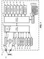
- FIG. 1is a block diagram of a wireless mobile device 100 incorporating a communication subsystem having both a receiver 112 and a transmitter 114, as well as associated components such as one or more embedded or internal antenna elements 116 and 118, local oscillators (L0s) 113, and a processing module such as a digital signal processor (DSP) 120.
- the particular design of the communication subsystemwill be dependent upon the communication network in which the device is intended to operate such as in a 3GPP LTE network.
- the wireless mobile device 100performs synchronization, registration or activation procedures by sending and receiving communication signals over the network 102.
- UL signals received by antenna 116 through communication network 100are input to receiver 112, which may perform such common receiver functions as signal amplification, frequency down conversion, filtering, channel selection and the like, and in the example system shown in FIG. 1 , analog to digital (A/D) conversion.
- A/D conversion of a received signalallows more complex communication functions such as demodulation, decoding and synchronization to be performed in the DSP 120.
- signals to be transmittedare processed, including modulation and encoding for example, by DSP 120 and input to transmitter 114 for digital to analog conversion, frequency up conversion, filtering, amplification and transmission over the communication network 102 via antenna 118.
- DSP 120not only processes communication signals, but also provides for receiver and transmitter control. For example, the gains applied to communication signals in receiver 112 and transmitter 114 may be adaptively controlled through automatic gain control algorithms implemented in DSP 120.
- Wireless device 100preferably includes a radio processor 111 and a control processor 138 which together control the overall operation of the device.
- DSP 120is located on radio processor 111. Communication functions are performed through radio processor 111.
- Radio processor 111interacts with receiver 112 and transmitter 114, and further with flash memory 162, random access memory (RAM) 160, the subscriber identity module 164, a headset 168, a speaker 170, and a microphone 172.
- flash memory 162random access memory (RAM) 160
- the subscriber identity module 164the subscriber identity module 164
- a headset 168the headset 168
- a speaker 170the speaker 170
- a microphone 172a microphone 172.
- Microprocessor 138interacts with further device subsystems such as the display 122, flash memory 140, random access memory (RAM) 136, auxiliary input/output (I/O) subsystems 128, serial port 130, keyboard 132, other communications 142 and other device subsystems generally designated as 144.
- display 122flash memory 140
- RAMrandom access memory
- I/Oauxiliary input/output subsystems 128, serial port 130, keyboard 132, other communications 142 and other device subsystems generally designated as 144.
- Some of the subsystems shown in Figure 1perform communication-related functions, whereas other subsystems may provide "resident" or on-device functions.
- some subsystemssuch as keyboard 132 and display 122, for example, may be used for both communication-related functions, such as entering a text message for transmission over a communication network, and device-resident functions such as a calculator or task list.
- Radio processor 111 and microprocessor 138is preferably stored in a persistent store such as flash memory 140 and 162, which may instead be a read-only memory (ROM) or similar storage element (not shown).
- ROMread-only memory
- Those skilled in the artwill appreciate that the operating system, specific device applications, or parts thereof, may be temporarily loaded into a volatile memory such as RAM 136 and RAM 260. Received communication signals may also be stored in RAM 136.
- flash memory 140can be segregated into different areas for computer programs 146, device state 148, address book 150, other personal information management (PIM) 152 and other functionality generally designated as 154. These different storage types indicate that each program can allocate a portion of flash memory 140 for their own data storage requirements.
- Control processor 138in addition to its operating system functions, preferably enables execution of software applications on the mobile station.
- wireless mobile device 100For voice communications, overall operation of wireless mobile device 100 is similar, except that received signals would preferably be output to the speaker 170 or headset 168 and signals for transmission would be generated by the microphone 172.
- Alternative voice or audio I/O subsystemssuch as a voice message recording subsystem, may also be implemented on mobile station 102.
- Serial port 130 in Figure 1would normally be implemented in a wireless mobile device that have PDA functionality for which synchronization with a user's desktop computer (not shown) may be desirable, but is an optional device component.
- a port 130would enable a user to set preferences through an external device or software application and would extend the capabilities of wireless mobile device 100 by providing for information or software downloads to wireless mobile device 100 other than through a wireless communication network.
- the alternate download pathmay for example be used to load an encryption key onto the device through a direct and thus reliable and trusted connection to thereby enable secure device communication.
- Other device subsystems 144such as a short-range communications subsystem, is a further optional component which may provide for communication between wireless mobile device 100 and different systems or devices, which need not necessarily be similar devices.
- the subsystem 144may include an infrared device and associated circuits and components or a BluetoothTM communication module to provide for communication with similarly enabled systems and devices.
- FIG. 2is a block diagram of wireless base station 103 connected to wireless network 102.
- the wireless base station 103communicates with a plurality of wireless mobile devices located in the service region.
- a receiver 212is coupled to one or more receive antennas 202 for processing signals from the wireless mobile devices.
- Downlink (DL) signals from wireless mobile devicesare received by antenna 202 are input to receiver 212, which may perform common receiver functions as signal amplification, frequency down conversion, filtering, channel selection and analog to digital (A/D) conversion.
- A/D conversion of a received signalallows more complex communication functions such as demodulation, decoding and synchronization to be performed in the receive processor 214.
- one or more transmit antennas 204are coupled to a transmitter 216.
- the transmitter 216provides frequency up-conversion including modulation, amplification and transmission over the communication to wireless mobile device 100. Digital to analog conversion and encoding can be performed by transmit processor 218.
- the processor 220provides additional processing of the received and transmitted signals and interfaces with backhaul interfaces 230 and OA&M 232 interfaces with the rest of the wireless network 102 for operation of the BTS 103.
- the receive processor 214may additional perform timing synchronization on signals received from wireless mobile devices 100 on the wireless network 102.
- FIG. 3shows a simplified OFDM transmitter 300 as would be implemented in transmitter 114 and DSP 120 in the wireless mobile device 100 and transmitter 216 and transmit processor 218 in the BTS 103.
- the inputis a sequence of reference symbols which is provided to serial to parallel converter 302.
- the parallel symbol streamis processed by an inverse-Fast Fourier transform (IFFT) 304 and converted by a parallel to serial converter 306.
- IFFTinverse-Fast Fourier transform
- a cyclic prefixcan then be inserted at 308 prior to digital to analog converter 310.
- the signalcan then be amplified and modulated before transmission via channel 312.
- Figure 4shows a simplified receiver 400.
- the signalUpon receiving the signal through channel 312, the signal is down-converted and demodulated.
- the analog to digital converter 402then provides a digital stream for cyclic prefix removal 404.
- the data streamis then converted from a serial to parallel stream at 406.
- FFTFast Fourier Transform
- the channel frequency responsecan be derived by dividing the received frequency-domain sequence by the reference sequence that is modulated on the sub-carriers.
- the simplest way to get the channel impulse responseis to do an Inverse Discrete Fourier Transform (IDFT) on the frequency response, either use a windowed IDFT or a non-windowed IDFT.
- IDFTInverse Discrete Fourier Transform
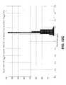
- Figure 5illustrates a typical urban radio channel (TU 30) delay profile which has been used for GSM system performance evaluation providing similar characteristics to an LTE system as would be defined by channel 312.
- Table 1shows the similarity of the channel impulse response estimation, signal spectrum estimation and the direction of arrival (DOA) estimation in array signal processing. Note that equally-spaced sampling on the observing domains is assumed for comparison purposes in the following table.
- Table 1. Similarity of timing, spectrum and DOA estimation Timing estimation Spectrum estimation DOA estimation Observation domain Frequency domain Time domain Space domain Samples of one observation Samples on different frequency (sub-carrier) Samples on different time Samples on different sensor of the array xx 1 f x 2 f ...
- ⁇ fdenotes the frequency spacing between each sample in frequency domain
- ⁇ Tdenotes the time spacing between each sample in time domain
- ldenotes the distance between each sensor of the array, carrier wavelength and signal arrival angle respectively.
- timing estimation, spectrum estimation and DOA estimationare all the same from a mathematical point of view. They differ only in that they have a different constant factor in the transformation vector. That means all the algorithms for spectrum estimation and DOA estimation can be used for timing estimation, if the frequency domain observations can be easily obtained.
- the channel frequency responsecan be easily obtained when the timing is roughly synchronized between the transmitter and the receiver.
- the UL frequencycan also be assumed to be synchronized.
- the radio propagation channelis generally modeled as multi-path channel. This channel model is similar with multiple, different frequency sinusoid wave signal model in spectrum estimation. It is also similar with the signal model in array signal processing that has multiple signals arrive from different directions. This similarity opens an opportunity to apply the DOA estimation algorithms and spectrum estimation algorithms to timing estimation, for example, linear Fourier Analyzing (FA) algorithm, sub-space decomposition based Multiple Signal Classification (MUSIC) algorithm, or sub-space fitting based Maximum Likelihood (ML) algorithm.
- FAlinear Fourier Analyzing
- MUSICsub-space decomposition based Multiple Signal Classification
- MLMaximum Likelihood
- Nnumber of total sub-carriers the SRS is transmitted on
- Kis the total number of SRS OFDM symbols sampled.
- c ⁇c 1 c 2 ... c N T denote the indexes of the sub-carriers assigned to the wireless mobile device.
- a constant amplitude complex sequence s 1 , s 2 ,...,s Nis used in LTE.
- ⁇ fis the sub-carrier spacing in the OFDM system. It is further assumed that the signal is a narrow bandwidth signal.
- n kdenotes the additive noise in the frequency domain.
- the sampled noise in time domainis additive white Gaussian noise. It is obvious that the frequency domain noise n k is still additive white Gaussian noise with independent identical distribution (i.i.d.).
- ⁇ /denotes the matrix element dividing operator.
- the above equationis the system signal model.
- the vector x kcan be simply obtained from the frequency domain observed vector r k .
- Unknown time offset parameters t 1 , t 2 , ..., t M within the matrix Aare the parameters that need to be estimated.
- the unknown channel complex parameters h kare not of interest for the LTE UL timing synchronization.
- LTE UL timing estimationA large number of algorithms for spectrum estimation and array signal DOA estimation can be applied in LTE UL timing estimation.
- Three well-known DOA estimation algorithmslinear Fourier Analyzing algorithm, sub-space decomposition based MUSIC algorithm and sub-space fitting based Maximum Likelihood (ML) algorithm, are presented for the LTE UL timing estimation without mathematic derivation.
- MLMaximum Likelihood
- the ( ⁇ ) H in above equationdenotes Hermitian operation.
- the covariance matrixcollects the information from all samples. Be aware that the covariance operation does not increase the SNR. It is not a coherent accumulation.
- the benefit of the covariance matrixis that it decreases the variance of the estimated noise power and signal power with increasing numbers of samples, but does not decrease the average noise power or increase the signal power.
- the exact covariance matrixshould not only be a Hermitian matrix (conjugate symmetric matrix), but also should a Teoplitz matrix, in which the value of the elements along each descending diagonal is a constant.
- the estimated covariance matrix Xwill lose the properties of Hermitian and Teoplitz matrix in some degree.
- the value of the matrix elements along each descending diagonalcan be replaced with their average value.
- m MUSIC t1 ⁇ a ⁇ ⁇ t H ⁇ E ⁇ N ⁇ ⁇ 2
- E Ndenotes the noise sub-space matrix of the covariance matrix X .
- the subspace-fitting based Maximum Likelihood (ML) algorithmhas more computational complexity, it involves a joint multiple dimension optimization.
- Figure 6presents a method of performing Long Term Evolution (LTE) Radio Link Timing Synchronization utilizing the techniques discussed above.
- LTELong Term Evolution
- a channel frequency response estimate x kis obtained from a received UL signal.
- the channel frequency response covariance matrix Xis then generated at 604.
- MUSIC and ML algorithmsa known number of multi-paths is required. There are some techniques that can be used to estimation the number of multi-paths, however it is assumed as a known parameter.
- YESat 606, they are generated at 608, and Fourier Analyzing and MUSIC timing offset estimation algorithms are identified as modified Fourier Analyzing (FAmod) algorithm and modified MUSIC (MUSICmod) algorithm respectively. Otherwise, NO at 606, original covariance matrix will be used.
- FAmodmodified Fourier Analyzing
- MUSICmodmodified MUSIC
- the position of the first peakoffers a more meaningful time delay estimate.
- the first-peak searchingcan then be performed through 618 to 630.
- the metric m ( t )is calculated according to FA or MUSIC algorithm in the defined searching window.
- the maximum and minimum value of the metric: m max and m min in the searching windowis found at 620.
- a searchis performed for first ascending point where the metric goes up at 626. From the point found at 626, a search is performed for the first descending point where the metric goes down at 628. This is the position of the first peak. From the first peak a timing estimate can be determined at 630. The estimate of the first peak is then used to synchronize the device to the UL and processing of overhead information can then proceed.
- NO at 612NO at 612, a multi-dimensional metric peak search is performed at 614 and a timing estimate is determined to enable synchronization to the UL.
- Simulation Case 1represents the cell edge situation in which low SNR, low SRS signal bandwidth and limited number of SRS OFDM symbols are available for timing estimation.
- the simulation parametersare set as: TU30 channel, ( Figure 5 illustrates the TU channel profile), 20 SRS symbols in rate of 40 Hz for one estimation; 6 resource blocks (RBs - each RB has 12 sub-carriers with 15 kHz spacing; all the sub-carriers are allocated continuously with each other); and -13.8 dB SNR.
- Simulation Case 2increases the SNR to 0 dB and the number of SRS OFDM symbols to 50 in rate of 100 Hz to simulation better radio link situation.
- Simulation Case 3further increases SRS signal bandwidth to 12 RBs to examine the performance potential of the algorithms.
- Table 2.Parameters used in the simulation cases.
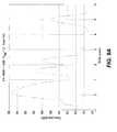
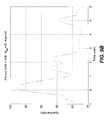
- Figures 7A-Dshow an example timing estimation metrics of the proposed algorithms in simulation Case 1.
- figures A to Dcorrespond to FA, FAmod, MUSIC and MUSICmod timing offset estimation algorithms respectively. It can be seen from this figure that the all proposed algorithms cannot resolve the first three peaks (see Figure 5 for the channel profile). While, the MUSIC and the modified MUSIC algorithms can show only one peak clearly.
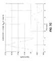
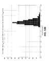
- Figures. 8A-Dshows, as an example, the algorithms' metrics in simulation Case 2. It can be seen from this figure that the modified MUSIC algorithm's resolution shows some improvement. It shows a total 5 peaks. The closely located first three peaks still can not be resolved. The FA and FAmod algorithms resolution don't have significant difference compared with that in case 1.
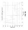
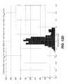
- FIG. 9A-Dshows the algorithm metric examples in simulation Case 3. With increased signal bandwidth, all four algorithms' resolution gets improved. From this figure, it can be seen that the FA and FAmod algorithms can resolve the two peaks located around the 2 ⁇ sec positions, the MUSIC algorithm shows two peaks in the first 0.5 ⁇ sec period, which should be three peaks. The modified MUSIC (MUSICmod) algorithm clearly resolves all peaks.
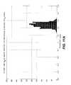
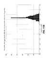
- Figures 10A-D to 12A-Dshow the algorithms' performance (histogram) in the three simulation cases.
- value of parameter ⁇ in the First-Peak Searching algorithmis set to 0.4 for all FA, FAmod, MUSIC, MUSICmod metrics.
- value of ⁇is set as 0.4 for FA and FAmod metrics, but 0.01 for MUSIC and MUSICmod metrics.
- the simulation resultswere taken from 2000 Monte-Carlo tests. The timing drift and Doppler frequency drift that cause by the wireless mobile device movement in one timing estimation have been taken into account in the simulation.
- Table 3The results of the algorithms' performance simulation are summarized in the following table. Table 3.
- the proposed timing estimate algorithmsare for LTE UL timing synchronization, they can be applied to DL link timing synchronization as well due to similar reference signal structure in both LTE uplink and downlink.
- LTELong Term Evolution
Landscapes
- Engineering & Computer Science (AREA)
- Computer Networks & Wireless Communication (AREA)
- Signal Processing (AREA)
- Mobile Radio Communication Systems (AREA)
- Synchronisation In Digital Transmission Systems (AREA)
- Electric Clocks (AREA)
Abstract
Description
- The present disclosure relates to mobile wireless networks and in particular to radio link timing synchronization of long term evolution based wireless networks.
- Timing and frequency synchronization is a crucial part of wireless communication such as Orthogonal Frequency Division Multiplexing (OFDM) technology based 3GPP Long Term Evolution (LTE) system. In fact, it is widely recognized that an OFDM based communication system is very sensitive to frequency and timing error and existing techniques do not meet the performance requirement for LTE uplink (UL) synchronization. The challenge for LTE UL timing synchronization is that, to keep the synchronization overhead as low as possible to preserve LTE system overall capacity, the radio resources are limited for timing estimation. That means only very narrow radio bandwidth, limited time duration and limited signal to noise ratio (SNR) for the reference signal are available, especially at cell edge. Accordingly, improved methods of radio link timing synchronization in LTE systems remain highly desirable.
- "OZIEWICZ M: "On Application of MUSIC Algorithm to Time Delay Estimation in OFDM Channels" IEEE TRANSACTIONS ON BROADCASTING, IEEE SERVICE CENTER, PISCATAWAY, NJ, US vol. 51, no. 2, 1 June 2005 (2005-06-01), pages 249-255, XP011132560 ISSN: 0018-9316 discloses that The time delays of the OFDM paths delimit the size of guard interval in OFDM symbols-important factor for system throughput. In order to apply guard interval as an adaptive parameter like in DRM system, time delays should have been evaluated in real time and in a simple way. Presented software method takes advantage of the information carried out by pilot subcarriers of the OFDM signal. It is shown that pilot subcarriers of OFDM signal in multipath channel are described by equations formally equivalent to equations of Direction-Of-Arrival (DOA) problem in antenna array processing. This analogy leads to application of the MUSIC algorithm of DOA problem to time delay estimation of the individual OFDM paths. Related condition for distribution of pilots within OFDM symbol is given. In case of time delays outside the guard interval the MUSIC algorithm is shown to produce 'shadow' and 'ghost' paths."
- In accordance with an embodiment of the present disclosure there is provided a method for performing a radio link timing estimation for synchronization to a 3GPP Long Term Evolution Uplink (UL) channel wireless communications channel according to
claim 1. - In accordance with another embodiment the present disclosure there is provided a mobile wireless device operating on wireless network according to claim 7.
- In accordance with another embodiment of the present disclosure there is provided a base station transceiver in a wireless network according to
claim 8. - Further features and advantages will become apparent from the following detailed description, taken in combination with the appended drawings, in which:
Figure 1 is a block diagram of wireless mobile device;Figure 2 is a block diagram of a wireless base station;Figure 3 is a schematic representation of a simplified OFDM transmitter;Figure 4 is a schematic representation of a simplified OFDM receiver;Figure 5 is graph of a typical urban channel delay profile;Figure 6 is a method of performing timing synchronization;Figures 7A-D are estimated time delay profiles forsimulation Case 1;Figures 8A-D are estimated time delay profiles forsimulation Case 2;Figures 9A-D are estimated time delay profiles forsimulation Case 3;Figures 10A-D are time estimation errors forsimulation Case 1;Figures 11A-D are time estimation errors forsimulation Case 2; andFigures 12 A-D are time estimation errors forsimulation Case 3.- It will be noted that throughout the appended drawings, like features are identified by like reference numerals.
- In Orthogonal Frequency Division Multiplexing (OFDM) technology based 3GPP Long Term Evolution (LTE) system, two types of timing estimation techniques: time-domain based techniques and frequency-domain based techniques can be used in the receivers during synchronization. When there is little or no frequency error, a very straightforward and very efficient timing estimation technique is the correlation technique. With this technique, the receiver in the time domain correlates a known sequence with the received sounding reference signal (SRS) or demodulation reference signal (DRS) that has been modulated by a known sequence. The result of the correlation produces a peak that indicates signal arriving time offset. This timing estimation technique relies on the good circular correlation properties of the reference sequence. Ideally, the sequence should have zero circular autocorrelation when the time shift is not zero. When there is no time shift, the circular autocorrelation should produce a very high peak. Sequences generated with Zadoff-Chu codes have this property.
- The correlation technique can directly be applied in a wireless multi-path environment. When the signal bandwidth is sufficiently wide, resolution of the different peaks (correspond to different paths) improves and this correlation technique can detect the time of arrival of the different paths by searching for the multiple correlation peaks. When a frequency offset (due to local oscillator drifting or Doppler shift) exists as well as the timing offset, the performance of this time domain correlation technique degrades to some degree.
- This time-domain correlation timing estimation technique is based on a known sequence with good circular correlation property. Another type of time-domain timing estimation is based on exploring the periodic pattern of the reference signal. In general, when there is no significant frequency offset, the timing estimation techniques based on simple correlation with known reference sequence has better performance than these techniques based on exploring the periodic pattern of the reference signal.
- For single-path radio propagation channels with ideal reflector, the channel impulse response would be a delta function with unknown time shift. This time shift is what the timing synchronization task needs to estimate and to correct later. In multi-path channel environment, the ideal channel impulse response would be multiple delta functions with different time shifts that correspond to the different paths' travel distances. The timing synchronization task should adjust the transmitter time to align the time of arrival of the first path with the receiver time.
Figure 1 is a block diagram of a wirelessmobile device 100 incorporating a communication subsystem having both areceiver 112 and atransmitter 114, as well as associated components such as one or more embedded orinternal antenna elements - The wireless
mobile device 100 performs synchronization, registration or activation procedures by sending and receiving communication signals over thenetwork 102. UL signals received byantenna 116 throughcommunication network 100 are input toreceiver 112, which may perform such common receiver functions as signal amplification, frequency down conversion, filtering, channel selection and the like, and in the example system shown inFIG. 1 , analog to digital (A/D) conversion. A/D conversion of a received signal allows more complex communication functions such as demodulation, decoding and synchronization to be performed in theDSP 120. - In a similar manner, signals to be transmitted are processed, including modulation and encoding for example, by
DSP 120 and input totransmitter 114 for digital to analog conversion, frequency up conversion, filtering, amplification and transmission over thecommunication network 102 viaantenna 118. DSP 120 not only processes communication signals, but also provides for receiver and transmitter control. For example, the gains applied to communication signals inreceiver 112 andtransmitter 114 may be adaptively controlled through automatic gain control algorithms implemented in DSP 120. Wireless device 100 preferably includes aradio processor 111 and acontrol processor 138 which together control the overall operation of the device. DSP 120 is located onradio processor 111. Communication functions are performed throughradio processor 111.Radio processor 111 interacts withreceiver 112 andtransmitter 114, and further withflash memory 162, random access memory (RAM) 160, thesubscriber identity module 164, aheadset 168, aspeaker 170, and amicrophone 172.Microprocessor 138 interacts with further device subsystems such as thedisplay 122,flash memory 140, random access memory (RAM) 136, auxiliary input/output (I/O)subsystems 128,serial port 130,keyboard 132,other communications 142 and other device subsystems generally designated as 144.- Some of the subsystems shown in
Figure 1 perform communication-related functions, whereas other subsystems may provide "resident" or on-device functions. Notably, some subsystems, such askeyboard 132 anddisplay 122, for example, may be used for both communication-related functions, such as entering a text message for transmission over a communication network, and device-resident functions such as a calculator or task list. - Software used by
radio processor 111 andmicroprocessor 138 is preferably stored in a persistent store such asflash memory RAM 136 and RAM 260. Received communication signals may also be stored inRAM 136. - As shown,
flash memory 140 can be segregated into different areas forcomputer programs 146,device state 148,address book 150, other personal information management (PIM) 152 and other functionality generally designated as 154. These different storage types indicate that each program can allocate a portion offlash memory 140 for their own data storage requirements.Control processor 138, in addition to its operating system functions, preferably enables execution of software applications on the mobile station. - For voice communications, overall operation of wireless
mobile device 100 is similar, except that received signals would preferably be output to thespeaker 170 orheadset 168 and signals for transmission would be generated by themicrophone 172. Alternative voice or audio I/O subsystems, such as a voice message recording subsystem, may also be implemented onmobile station 102. Serial port 130 inFigure 1 would normally be implemented in a wireless mobile device that have PDA functionality for which synchronization with a user's desktop computer (not shown) may be desirable, but is an optional device component. Such aport 130 would enable a user to set preferences through an external device or software application and would extend the capabilities of wirelessmobile device 100 by providing for information or software downloads to wirelessmobile device 100 other than through a wireless communication network. The alternate download path may for example be used to load an encryption key onto the device through a direct and thus reliable and trusted connection to thereby enable secure device communication.Other device subsystems 144, such as a short-range communications subsystem, is a further optional component which may provide for communication between wirelessmobile device 100 and different systems or devices, which need not necessarily be similar devices. For example, thesubsystem 144 may include an infrared device and associated circuits and components or a Bluetooth™ communication module to provide for communication with similarly enabled systems and devices.Figure 2 is a block diagram ofwireless base station 103 connected towireless network 102. Thewireless base station 103 communicates with a plurality of wireless mobile devices located in the service region. Areceiver 212 is coupled to one or more receiveantennas 202 for processing signals from the wireless mobile devices. Downlink (DL) signals from wireless mobile devices are received byantenna 202 are input toreceiver 212, which may perform common receiver functions as signal amplification, frequency down conversion, filtering, channel selection and analog to digital (A/D) conversion. A/D conversion of a received signal allows more complex communication functions such as demodulation, decoding and synchronization to be performed in the receiveprocessor 214. In the transmission path, one or more transmitantennas 204 are coupled to atransmitter 216. Thetransmitter 216 provides frequency up-conversion including modulation, amplification and transmission over the communication to wirelessmobile device 100. Digital to analog conversion and encoding can be performed by transmitprocessor 218. Theprocessor 220 provides additional processing of the received and transmitted signals and interfaces withbackhaul interfaces 230 andOA&M 232 interfaces with the rest of thewireless network 102 for operation of theBTS 103. The receiveprocessor 214 may additional perform timing synchronization on signals received from wirelessmobile devices 100 on thewireless network 102.- In OFDM systems, it is much easer to estimate the channel frequency response than to estimate channel impulse response directly. Under the assumption that the transmitter and receiver are roughly synchronized, the receiver can correctly sample the wireless mobile device's UL SRS OFDM symbol without inter symbol interference (ISI).
Figure 3 shows asimplified OFDM transmitter 300 as would be implemented intransmitter 114 andDSP 120 in the wirelessmobile device 100 andtransmitter 216 and transmitprocessor 218 in theBTS 103. The input is a sequence of reference symbols which is provided to serial toparallel converter 302. The parallel symbol stream is processed by an inverse-Fast Fourier transform (IFFT) 304 and converted by a parallel toserial converter 306. A cyclic prefix can then be inserted at 308 prior to digital toanalog converter 310. The signal can then be amplified and modulated before transmission viachannel 312. Figure 4 shows asimplified receiver 400. Upon receiving the signal throughchannel 312, the signal is down-converted and demodulated. The analog todigital converter 402 then provides a digital stream forcyclic prefix removal 404. The data stream is then converted from a serial to parallel stream at 406. Taking an Fast Fourier Transform (FFT) 408 of this time-domain sampled sequence to transform it into the frequency domain, the channel frequency response can be derived by dividing the received frequency-domain sequence by the reference sequence that is modulated on the sub-carriers. The simplest way to get the channel impulse response is to do an Inverse Discrete Fourier Transform (IDFT) on the frequency response, either use a windowed IDFT or a non-windowed IDFT.Figure 5 illustrates a typical urban radio channel (TU 30) delay profile which has been used for GSM system performance evaluation providing similar characteristics to an LTE system as would be defined bychannel 312. Table 1 shows the similarity of the channel impulse response estimation, signal spectrum estimation and the direction of arrival (DOA) estimation in array signal processing. Note that equally-spaced sampling on the observing domains is assumed for comparison purposes in the following table.Table 1. Similarity of timing, spectrum and DOA estimation Timing estimation Spectrum estimation DOA estimation Observation domain Frequency domain Time domain Space domain Samples of one observation Samples on different frequency (sub-carrier) Samples on different time Samples on different sensor of the array x =


Target domain Time domain Frequency domain DOA angle domain (cos(θ) domain) Domain transformation vector a 


Domain IDFT DFT DFT-like transformation transformation a (t)T ·x a (f)T·x a (θ)T·x - In the table above, Δf denotes the frequency spacing between each sample in frequency domain; ΔT denotes the time spacing between each sample in time domain; andl, λ and θ denote the distance between each sensor of the array, carrier wavelength and signal arrival angle respectively.
- From the comparison in table 1, it can be seen that the timing estimation, spectrum estimation and DOA estimation are all the same from a mathematical point of view. They differ only in that they have a different constant factor in the transformation vector. That means all the algorithms for spectrum estimation and DOA estimation can be used for timing estimation, if the frequency domain observations can be easily obtained.
- In an OFDM system like LTE, the channel frequency response can be easily obtained when the timing is roughly synchronized between the transmitter and the receiver. The UL frequency can also be assumed to be synchronized. The radio propagation channel is generally modeled as multi-path channel. This channel model is similar with multiple, different frequency sinusoid wave signal model in spectrum estimation. It is also similar with the signal model in array signal processing that has multiple signals arrive from different directions. This similarity opens an opportunity to apply the DOA estimation algorithms and spectrum estimation algorithms to timing estimation, for example, linear Fourier Analyzing (FA) algorithm, sub-space decomposition based Multiple Signal Classification (MUSIC) algorithm, or sub-space fitting based Maximum Likelihood (ML) algorithm.
- Current LTE UL timing estimation algorithms use just one OFDM symbol to estimate the signal timing offset; therefore, relatively high signal to noise ratio (SNR) is required for these algorithms to be effective. At the cell edge, the SNR is normally very low and these algorithms may not meet the LTE system performance requirement.
- It is assumed that the wireless mobile device uplink is already roughly synchronized. That means the wireless mobile device UL timing offset is within a certain range. In this range, with the cyclic prefix (CP) in place, the enhanced Node B (eNB) can correctly sample the SRS OFDM symbol's baseband signal in time domain without any ISI, but the timing offset information is contained in the samples. It is also assumed that the wireless mobile device's frequency error is small and can be ignored. (Frequency offset estimation and correction will not be discussed in this disclosure). After the FFT operation on these time domain samples, a frequency domain sample of the SRS OFDM symbol can be obtained. Note

- as the sampled vector of thek -th SRS OFDM symbol in frequency domain at the sub-carriers that the wireless mobile device is assigned to transmit the SRS. Where,N is number of total sub-carriers the SRS is transmitted on, andK is the total number of SRS OFDM symbols sampled. Let

- The SRS reference sequence (the input in
Figure 3 ) is noted as:
- Generally, a constant amplitude complex sequences1,s2,...,sN is used in LTE.
- Assume that there are M multi-paths in the radio propagation channel with different time delaystm and complex attenuation factor


- Where Δf is the sub-carrier spacing in the OFDM system. It is further assumed that the signal is a narrow bandwidth signal. With the above assumptions and notations, the frequency domain sample of the received baseband signal for thek -th SRS OFDM symbol can be expressed as:

- In the equations above, the "o" denotes the Hadamard product (matrix element product) operator, and
n k denotes the additive noise in the frequency domain. We assume that the sampled noise in time domain is additive white Gaussian noise. It is obvious that the frequency domain noisen k is still additive white Gaussian noise with independent identical distribution (i.i.d.). - The estimate of the channel frequency response based on thek -th SRS OFDM symbol is denoted as:

- From the discussion above, the channel frequency response can be estimated as:

- Where "·/" denotes the matrix element dividing operator. With the assumption that the SRS reference sequence in frequency domain has constant amplitude across the sub-carriers, it is easy to see that
n k ../s is still white Gaussian noise with independent identical distribution. We still make the following note for simplicity:
- The above equation is the system signal model. In the equation, the vector
x k can be simply obtained from the frequency domain observed vectorrk . Unknown time offset parameterst1, t2, ...,tM within the matrixA are the parameters that need to be estimated. The unknown channel complex parametersh k are not of interest for the LTE UL timing synchronization. - A large number of algorithms for spectrum estimation and array signal DOA estimation can be applied in LTE UL timing estimation. Three well-known DOA estimation algorithms, linear Fourier Analyzing algorithm, sub-space decomposition based MUSIC algorithm and sub-space fitting based Maximum Likelihood (ML) algorithm, are presented for the LTE UL timing estimation without mathematic derivation.
- It should be pointed out that the current timing offset estimation algorithms are based on single OFDM symbol samples. In the present disclosure samples of multiple non-coherent OFDM symbols are used to combat low SNR at the cell edge of LTE system.
- First, the covariance matrix of the channel frequency response is estimated as:

- The (·)H in above equation denotes Hermitian operation. The covariance matrix collects the information from all samples. Be aware that the covariance operation does not increase the SNR. It is not a coherent accumulation. The benefit of the covariance matrix is that it decreases the variance of the estimated noise power and signal power with increasing numbers of samples, but does not decrease the average noise power or increase the signal power.
- If the frequency response is sampled with equal spacing in frequency domain, the exact covariance matrix (mathematically expectation) should not only be a Hermitian matrix (conjugate symmetric matrix), but also should a Teoplitz matrix, in which the value of the elements along each descending diagonal is a constant. With a limited number of symbols (small value ofK), the estimated covariance matrix
X will lose the properties of Hermitian and Teoplitz matrix in some degree. To improve the covariance matrix estimate accuracy, the value of the matrix elements along each descending diagonal can be replaced with their average value. Mathematically, the averaged covariance matrix can be expressed as:
x̂ i of the averaged matrixis calculated from the elements xl,m of the matrix
X as:
- Notation (5) is rewritten as:

- The linear Fourier Analyzing (FA) algorithm is given as searching for the position in time axis where the following metric reaches its peaks:

- The sub-space decomposition based MUSIC algorithm's searching metric is given by:

- Where, in above equation,
E N denotes the noise sub-space matrix of the covariance matrixX .E N is composed of (N-M) eigenvectors corresponding to the(N-M) smallest eigenvalues of the matrixX and can be expressed as:E N = [e 1,e 2,...,e N-M], where ∥·∥ denotes vector norm operation. - The subspace-fitting based Maximum Likelihood (ML) algorithm has more computational complexity, it involves a joint multiple dimension optimization. The ML algorithm can be formulated as:


- Where,
P A(t1,t2,..,tM)=A .(A A)-1·A H is a projection matrix ofA and it is a function of the multiple time offset of the propagation paths. - It is well known that the ML performs better than the FA and MUSIC timing offset estimation algorithms, especially with a limited number of samples and limited SNR. However, the additional computational complexity is very costly to implement with present hardware technology.
Figure 6 presents a method of performing Long Term Evolution (LTE) Radio Link Timing Synchronization utilizing the techniques discussed above. At 602 a channel frequency response estimatex k is obtained from a received UL signal. The channel frequency response covariance matrixX is then generated at 604. For MUSIC and ML algorithms a known number of multi-paths is required. There are some techniques that can be used to estimation the number of multi-paths, however it is assumed as a known parameter. When the averaged covariance matrixX is to be utilized, YES at 606, they are generated at 608, and Fourier Analyzing and MUSIC timing offset estimation algorithms are identified as modified Fourier Analyzing (FAmod) algorithm and modified MUSIC (MUSICmod) algorithm respectively. Otherwise, NO at 606, original covariance matrix will be used.- For one-dimensional metrics timing offset estimation algorithms, for example, FA algorithm and MUSIC algorithm, YES at 612, the position of the first peak offers a more meaningful time delay estimate. The first-peak searching can then be performed through 618 to 630. The metricm(t) is calculated according to FA or MUSIC algorithm in the defined searching window. The maximum and minimum value of the metric:mmax andmmin in the searching window is found at 620. The threshold asmth = mmin + α · (mmax -mmin) is calculated at 622 where α takes value from 0 to 1. The metric is limited bym(t) = max (m(t),mth) to reduce the chance of finding false peak at 624. A search is performed for first ascending point where the metric goes up at 626. From the point found at 626, a search is performed for the first descending point where the metric goes down at 628. This is the position of the first peak. From the first peak a timing estimate can be determined at 630. The estimate of the first peak is then used to synchronize the device to the UL and processing of overhead information can then proceed. For multi-dimensional algorithms like ML algorithm, NO at 612, a multi-dimensional metric peak search is performed at 614 and a timing estimate is determined to enable synchronization to the UL.
- Simulations are presented for the Fourier Analyzing (FA) algorithm and MUSIC algorithm in three cases for LTE UL timing synchronization in
Figures 7 to 12 . Simulation Case 1 represents the cell edge situation in which low SNR, low SRS signal bandwidth and limited number of SRS OFDM symbols are available for timing estimation. The simulation parameters are set as: TU30 channel, (Figure 5 illustrates the TU channel profile), 20 SRS symbols in rate of 40 Hz for one estimation; 6 resource blocks (RBs - each RB has 12 sub-carriers with 15 kHz spacing; all the sub-carriers are allocated continuously with each other); and -13.8 dB SNR.Simulation Case 2 increases the SNR to 0 dB and the number of SRS OFDM symbols to 50 in rate of 100 Hz to simulation better radio link situation.Simulation Case 3 further increases SRS signal bandwidth to 12 RBs to examine the performance potential of the algorithms. These three cases are summarized in Table 2.Table 2. Parameters used in the simulation cases. Channel Model SRS symbols/Rate (Hz) Number of RBs SNR (dB) Case 1TU30 20/40 6 -13.8 Case 2TU30 50/100 6 0 Case 3TU30 50/100 12 0 Figures 7A-D show an example timing estimation metrics of the proposed algorithms insimulation Case 1. Withfigures 7A-D and the following figures, figures A to D correspond to FA, FAmod, MUSIC and MUSICmod timing offset estimation algorithms respectively. It can be seen from this figure that the all proposed algorithms cannot resolve the first three peaks (seeFigure 5 for the channel profile). While, the MUSIC and the modified MUSIC algorithms can show only one peak clearly.Figures. 8A-D shows, as an example, the algorithms' metrics insimulation Case 2. It can be seen from this figure that the modified MUSIC algorithm's resolution shows some improvement. It shows a total 5 peaks. The closely located first three peaks still can not be resolved. The FA and FAmod algorithms resolution don't have significant difference compared with that incase 1.Figures. 9A-D shows the algorithm metric examples insimulation Case 3. With increased signal bandwidth, all four algorithms' resolution gets improved. From this figure, it can be seen that the FA and FAmod algorithms can resolve the two peaks located around the 2 µsec positions, the MUSIC algorithm shows two peaks in the first 0.5 µsec period, which should be three peaks. The modified MUSIC (MUSICmod) algorithm clearly resolves all peaks.Figures 10A-D to 12A-D show the algorithms' performance (histogram) in the three simulation cases. Insimulation Case 1, value of parameter α in the First-Peak Searching algorithm is set to 0.4 for all FA, FAmod, MUSIC, MUSICmod metrics. InCase 2 andCase 3, value of α is set as 0.4 for FA and FAmod metrics, but 0.01 for MUSIC and MUSICmod metrics. The simulation results were taken from 2000 Monte-Carlo tests. The timing drift and Doppler frequency drift that cause by the wireless mobile device movement in one timing estimation have been taken into account in the simulation. The results of the algorithms' performance simulation are summarized in the following table.Table 3. Simulation results summary FA
(µsec)FAmod
(µsec)MUSIC
(µsec)MUSICmod
(µsec)Case 1Mean 0.23 0.23 0.23 0.23 Std 0.15 0.13 0.16 0.14 95th Percentile 0.23 0.22 us 0.25 0.23 Case 2Mean 0.24 0.24 0.23 0.08 Std 0.03 0.03 0.04 0.04 95th Percentile 0.06 0.06 0.09 0.08 Case 3Mean 0.18 0.18 0.13 0.02 Std 0.04 0.05 0.02 0.06 95th Percentile 0.08 0.09 0.04 0.13 - From the simulation results, it can be seen that all these algorithms meet the 0.5 µsec 95th percentile performance requirement for LTE UL timing synchronization even in worst case of the three simulation scenarios. In
simulation Case 1 with low SNR, narrow bandwidth, and low number of SRS OFDM symbols, the FA, FAmod, MUSIC and MUSICmod algorithms have similar performance. Insimulation Case 2, which has high SNR, more SRS OFDM symbols, but same bandwidth comparing withCase 1, the MUSICmod algorithm has significantly improved the performance of the mean error of the time estimate. However, the performance of the standard deviation (STD) and 95th percentile of the timing estimation of MUSIC and MUSICmod algorithms have decreased slightly comparing to the FA and FAmod algorithms. Insimulation Case 3, where the signal bandwidth is doubled comparing with incase 2, the MUSIC algorithm has slightly better mean error, STD and 95th percentile performance than FA and FAmod algorithms. While, the MUSICmod algorithm has the greatest mean error performance, although has slightly worse STD and 95th percentile performance, comparing with other algorithms. This very low mean error performance of the MUSICmod algorithm has benefited from the high resolution of the algorithm. - Though the proposed timing estimate algorithms are for LTE UL timing synchronization, they can be applied to DL link timing synchronization as well due to similar reference signal structure in both LTE uplink and downlink.
- While a particular embodiment of the present method for Long Term Evolution (LTE) Radio Link timing synchronization has been described herein, it will be appreciated by those skilled in the art that changes and modifications may be made thereto without departing from the disclosure in its broadest aspects and as set forth in the following claims.


Claims (8)
- A method for performing a radio link timing estimation for synchronization to a wireless communications channel, the method comprising:obtaining a channel frequency response (602) estimate
x k fork=1,2...K from a received reference signal comprising Orthogonal Frequency Division Multiplexing (OFDM) symbols by determining:
r k denotes the k-th received OFDM symbol in frequency domain, ands is transmitted reference sequence;
wherex k can be expressed as:


where, out of M multiple paths, each pathm has a different time delaytm and a different complex attenuation factor
whereK is the total number of OFDM symbols sampled, Δf denotes the frequency spacing between each sample in frequency domain, andc = [c1, c2...,cN]T denote the indices of the OFDM subcarriers;generating a frequency response covariance matrix (604) estimating timing offsets (618) by searching for the position in time where the metricmBF(t)=
a (t)H· X·a (t), witha (t) =[ej2πΔfc1 t,ej2πΔfc2 t,...,ej2πΔfcNt]T reaches its peaks. - The method of claim 1 wherein estimating timing offsets further comprises using an averaged covariance matrix (608) where the value of the matrix elements along each descending diagonal are replaced with their average value.
- The method of claim 2 wherein the covariance matrix is represented by:
 is calculated from the elementsxl,m of the matrix
X as:
- The method of any one of claims 1 to 3 further comprising:determining (620) a maximum valuemmax and a minimum valuemmin within the search window;determining (622) a threshold valuemth = mmin +α· (mmax- mmin) using the determine maximum value and minimum value, where α takes value from 0 to 1;limiting (624) the metric to the determined threshold;searching (626) for a first ascending point of the metric;searching (628) for a first descending point of the metric; anddetermining (630) a timing estimate based upon the peak identified by the first ascending and descending points from the timing estimates.
- The method of anyone of claim 1 to 4 wherein the reference signal is an OFDM sounding reference signal, SRS.
- The method of claim 1 wherein the wireless communications channel is based on a 3GPP Long Term Evolution Uplink, UL, channel.
- A mobile wireless device (100) for operating on wireless network, the mobile wireless device comprising:a receiver (112); anda processor (111) coupled to the receiver, the processor adapted to perform a radio link timing estimation for synchronization to a wireless communications channel by performing the method according to any one of claims 1 to 6.
- A base station transceiver (102) for use in a wireless network, the base station transceiver comprising:a receiver (212); and
a processor (214) coupled to the receiver, the processor adapted to perform a radio link timing estimation for synchronization to a wireless communications channel by performing the method according to any one of claims 1 to 6.


Priority Applications (6)
| Application Number | Priority Date | Filing Date | Title |
|---|---|---|---|
| EP08164304AEP2164217B1 (en) | 2008-09-12 | 2008-09-12 | Long term evolution (LTE) radio link timing synchronization |
| AT08164304TATE510392T1 (en) | 2008-09-12 | 2008-09-12 | TIME SYNCHRONIZATION OF LONG-TERM EVOLUTION RADIO CONNECTIONS |
| EP12179062AEP2523415A1 (en) | 2008-09-12 | 2009-09-14 | Long Term Evolution (LTE) Radio Link Timing Synchronization |
| CA2735007ACA2735007C (en) | 2008-09-12 | 2009-09-14 | Long term evolution (lte) radio link timing synchronization |
| PCT/CA2009/001276WO2010028502A1 (en) | 2008-09-12 | 2009-09-14 | Long term evolution (lte) radio link timing synchronization |
| EP09812585AEP2363005A4 (en) | 2008-09-12 | 2009-09-14 | Long term evolution (lte) radio link timing synchronization |
Applications Claiming Priority (1)
| Application Number | Priority Date | Filing Date | Title |
|---|---|---|---|
| EP08164304AEP2164217B1 (en) | 2008-09-12 | 2008-09-12 | Long term evolution (LTE) radio link timing synchronization |
Publications (2)
| Publication Number | Publication Date |
|---|---|
| EP2164217A1 EP2164217A1 (en) | 2010-03-17 |
| EP2164217B1true EP2164217B1 (en) | 2011-05-18 |
Family
ID=40666854
Family Applications (3)
| Application Number | Title | Priority Date | Filing Date |
|---|---|---|---|
| EP08164304AActiveEP2164217B1 (en) | 2008-09-12 | 2008-09-12 | Long term evolution (LTE) radio link timing synchronization |
| EP12179062AWithdrawnEP2523415A1 (en) | 2008-09-12 | 2009-09-14 | Long Term Evolution (LTE) Radio Link Timing Synchronization |
| EP09812585AWithdrawnEP2363005A4 (en) | 2008-09-12 | 2009-09-14 | Long term evolution (lte) radio link timing synchronization |
Family Applications After (2)
| Application Number | Title | Priority Date | Filing Date |
|---|---|---|---|
| EP12179062AWithdrawnEP2523415A1 (en) | 2008-09-12 | 2009-09-14 | Long Term Evolution (LTE) Radio Link Timing Synchronization |
| EP09812585AWithdrawnEP2363005A4 (en) | 2008-09-12 | 2009-09-14 | Long term evolution (lte) radio link timing synchronization |
Country Status (4)
| Country | Link |
|---|---|
| EP (3) | EP2164217B1 (en) |
| AT (1) | ATE510392T1 (en) |
| CA (1) | CA2735007C (en) |
| WO (1) | WO2010028502A1 (en) |
Families Citing this family (6)
| Publication number | Priority date | Publication date | Assignee | Title |
|---|---|---|---|---|
| CN102647781A (en)* | 2011-02-17 | 2012-08-22 | 中兴通讯股份有限公司 | Method for TA (Time Advance) regulation of LTE (Long Term Evolution) and base station |
| CN103036833B (en)* | 2011-09-30 | 2017-10-13 | 锐迪科(重庆)微电子科技有限公司 | A kind of ofdm system Timing Synchronization control method and device |
| WO2013125925A1 (en)* | 2012-02-24 | 2013-08-29 | 엘지전자 주식회사 | Method and device for tracking synchronization |
| GB2536538B (en) | 2014-09-17 | 2018-07-18 | Cardiomech As | Anchor for implantation in body tissue |
| US20220015906A1 (en) | 2018-11-29 | 2022-01-20 | Cardiomech As | Device for Heart Repair |
| CN116669174B (en)* | 2023-04-07 | 2025-09-12 | 上海物骐微电子有限公司 | Wi-Fi signal-based sensing method and device, electronic device, and storage medium |
Family Cites Families (6)
| Publication number | Priority date | Publication date | Assignee | Title |
|---|---|---|---|---|
| US4547899A (en)* | 1982-09-30 | 1985-10-15 | Ncr Corporation | Waveform matching system and method |
| US5495256A (en)* | 1994-03-07 | 1996-02-27 | Piper; John E. | Method of efficiently computing maximum likelihood bearing estimator |
| FR2798542B1 (en)* | 1999-09-13 | 2002-01-18 | France Telecom | ORTHOGONAL FREQUENCY DIVISION MULTIPLEXING RECEIVER WITH ITERATIVE CHANNEL ESTIMATION AND CORRESPONDING METHOD |
| US7551547B2 (en)* | 2005-01-28 | 2009-06-23 | At&T Intellectual Property I, L.P. | Delay restricted channel estimation for multi-carrier systems |
| US7995688B2 (en)* | 2007-03-08 | 2011-08-09 | Her Majesty The Queen In Right Of Canada, As Represented By The Minister Of Industry, Through The Communications Research Centre Canada | Channel estimation and ICI cancellation for OFDM |
| US20080219343A1 (en)* | 2007-03-09 | 2008-09-11 | Sharp Laboratories Of America, Inc. | Systems and methods for processing a signal within a communications system with a superimposed reference signal |
- 2008
- 2008-09-12EPEP08164304Apatent/EP2164217B1/enactiveActive
- 2008-09-12ATAT08164304Tpatent/ATE510392T1/ennot_activeIP Right Cessation
- 2009
- 2009-09-14EPEP12179062Apatent/EP2523415A1/ennot_activeWithdrawn
- 2009-09-14WOPCT/CA2009/001276patent/WO2010028502A1/enactiveApplication Filing
- 2009-09-14EPEP09812585Apatent/EP2363005A4/ennot_activeWithdrawn
- 2009-09-14CACA2735007Apatent/CA2735007C/ennot_activeExpired - Fee Related
Also Published As
| Publication number | Publication date |
|---|---|
| EP2164217A1 (en) | 2010-03-17 |
| EP2363005A1 (en) | 2011-09-07 |
| CA2735007A1 (en) | 2010-03-18 |
| CA2735007C (en) | 2014-08-12 |
| WO2010028502A1 (en) | 2010-03-18 |
| EP2523415A1 (en) | 2012-11-14 |
| EP2363005A4 (en) | 2011-09-14 |
| ATE510392T1 (en) | 2011-06-15 |
Similar Documents
| Publication | Publication Date | Title |
|---|---|---|
| US8116394B2 (en) | Long term evolution (LTE) radio link timing synchronization | |
| US8565787B2 (en) | RF fingerprinting for location estimation | |
| CN101496325B (en) | Interference noise estimation method, reception processing method, interference noise estimation device and receiver in multi-carrier communication system | |
| US8446894B2 (en) | Systems and methods for performing initial synchronization in wireless communications systems | |
| US8023595B2 (en) | Method and system of time-of-arrival estimation for ultra wideband multi-band orthogonal frequency division multiplexing signals | |
| US20190086505A1 (en) | Methods for estimating angle of arrival or angle of departure | |
| US20060039451A1 (en) | Method and apparatus for fast cell search | |
| US20100226454A1 (en) | Method and apparatus for synchronizing a wireless communication system | |
| EP2164217B1 (en) | Long term evolution (LTE) radio link timing synchronization | |
| US8588204B2 (en) | Efficient channel estimation method using superimposed training for equalization in uplink OFDMA systems | |
| US10284280B2 (en) | Method, system and device for compensation of Doppler impairments in OFDM wireless communication networks | |
| CN112702290B (en) | Channel estimation method and device | |
| US8411773B2 (en) | Simplified equalization scheme for distributed resource allocation in multi-carrier systems | |
| US20070002959A1 (en) | Apparatus and method for detecting user in a communication system | |
| Fan et al. | Power allocation for cell-free massive MIMO ISAC systems with OTFS signal | |
| Keskin et al. | Integrated sensing and communications with MIMO-OTFS | |
| US8218423B2 (en) | Ranging apparatus and method for improving ranging performance in OFDMA system | |
| Bacchielli et al. | Performance analysis of a low-complexity OTFS integrated sensing and communication system | |
| KR100668669B1 (en) | Initial frame synchronization acquisition device in terminal of orthogonal frequency division multiple access wireless communication system | |
| Zhang et al. | Pilot-Based Delay and Doppler Estimation In 6G Integrated Communication And Sensing Networks | |
| Noschese et al. | A low-complexity approach for time of arrival estimation in OFDM systems | |
| JP4809445B2 (en) | Apparatus and method for measuring radio quality | |
| US9413563B2 (en) | Method and apparatus for channel estimation using localized SINR in wireless communication systems | |
| La Pan et al. | Protecting physical layer synchronization: Mitigating attacks against OFDM acquisition | |
| Suyoto et al. | Improved timing estimation using iterative normalization technique for OFDM systems |
Legal Events
| Date | Code | Title | Description |
|---|---|---|---|
| PUAI | Public reference made under article 153(3) epc to a published international application that has entered the european phase | Free format text:ORIGINAL CODE: 0009012 | |
| 17P | Request for examination filed | Effective date:20080912 | |
| AK | Designated contracting states | Kind code of ref document:A1 Designated state(s):AT BE BG CH CY CZ DE DK EE ES FI FR GB GR HR HU IE IS IT LI LT LU LV MC MT NL NO PL PT RO SE SI SK TR | |
| AX | Request for extension of the european patent | Extension state:AL BA MK RS | |
| AKX | Designation fees paid | Designated state(s):AT BE BG CH CY CZ DE DK EE ES FI FR GB GR HR HU IE IS IT LI LT LU LV MC MT NL NO PL PT RO SE SI SK TR | |
| AXX | Extension fees paid | Extension state:MK Payment date:20080912 Extension state:RS Payment date:20080912 Extension state:BA Payment date:20080912 Extension state:AL Payment date:20080912 | |
| GRAP | Despatch of communication of intention to grant a patent | Free format text:ORIGINAL CODE: EPIDOSNIGR1 | |
| 17Q | First examination report despatched | Effective date:20101027 | |
| GRAS | Grant fee paid | Free format text:ORIGINAL CODE: EPIDOSNIGR3 | |
| GRAA | (expected) grant | Free format text:ORIGINAL CODE: 0009210 | |
| REG | Reference to a national code | Ref country code:GB Ref legal event code:FG4D | |
| REG | Reference to a national code | Ref country code:CH Ref legal event code:EP | |
| REG | Reference to a national code | Ref country code:IE Ref legal event code:FG4D | |
| REG | Reference to a national code | Ref country code:DE Ref legal event code:R096 Ref document number:602008007048 Country of ref document:DE Effective date:20110630 | |
| REG | Reference to a national code | Ref country code:SE Ref legal event code:TRGR | |
| REG | Reference to a national code | Ref country code:NL Ref legal event code:VDEP Effective date:20110518 | |
| PG25 | Lapsed in a contracting state [announced via postgrant information from national office to epo] | Ref country code:HR Free format text:LAPSE BECAUSE OF FAILURE TO SUBMIT A TRANSLATION OF THE DESCRIPTION OR TO PAY THE FEE WITHIN THE PRESCRIBED TIME-LIMIT Effective date:20110518 Ref country code:PT Free format text:LAPSE BECAUSE OF FAILURE TO SUBMIT A TRANSLATION OF THE DESCRIPTION OR TO PAY THE FEE WITHIN THE PRESCRIBED TIME-LIMIT Effective date:20110919 Ref country code:NO Free format text:LAPSE BECAUSE OF FAILURE TO SUBMIT A TRANSLATION OF THE DESCRIPTION OR TO PAY THE FEE WITHIN THE PRESCRIBED TIME-LIMIT Effective date:20110818 Ref country code:LT Free format text:LAPSE BECAUSE OF FAILURE TO SUBMIT A TRANSLATION OF THE DESCRIPTION OR TO PAY THE FEE WITHIN THE PRESCRIBED TIME-LIMIT Effective date:20110518 | |
| PG25 | Lapsed in a contracting state [announced via postgrant information from national office to epo] | Ref country code:GR Free format text:LAPSE BECAUSE OF FAILURE TO SUBMIT A TRANSLATION OF THE DESCRIPTION OR TO PAY THE FEE WITHIN THE PRESCRIBED TIME-LIMIT Effective date:20110819 Ref country code:BE Free format text:LAPSE BECAUSE OF FAILURE TO SUBMIT A TRANSLATION OF THE DESCRIPTION OR TO PAY THE FEE WITHIN THE PRESCRIBED TIME-LIMIT Effective date:20110518 Ref country code:IS Free format text:LAPSE BECAUSE OF FAILURE TO SUBMIT A TRANSLATION OF THE DESCRIPTION OR TO PAY THE FEE WITHIN THE PRESCRIBED TIME-LIMIT Effective date:20110918 Ref country code:CY Free format text:LAPSE BECAUSE OF FAILURE TO SUBMIT A TRANSLATION OF THE DESCRIPTION OR TO PAY THE FEE WITHIN THE PRESCRIBED TIME-LIMIT Effective date:20110518 Ref country code:ES Free format text:LAPSE BECAUSE OF FAILURE TO SUBMIT A TRANSLATION OF THE DESCRIPTION OR TO PAY THE FEE WITHIN THE PRESCRIBED TIME-LIMIT Effective date:20110829 Ref country code:AT Free format text:LAPSE BECAUSE OF FAILURE TO SUBMIT A TRANSLATION OF THE DESCRIPTION OR TO PAY THE FEE WITHIN THE PRESCRIBED TIME-LIMIT Effective date:20110518 Ref country code:LV Free format text:LAPSE BECAUSE OF FAILURE TO SUBMIT A TRANSLATION OF THE DESCRIPTION OR TO PAY THE FEE WITHIN THE PRESCRIBED TIME-LIMIT Effective date:20110518 Ref country code:SI Free format text:LAPSE BECAUSE OF FAILURE TO SUBMIT A TRANSLATION OF THE DESCRIPTION OR TO PAY THE FEE WITHIN THE PRESCRIBED TIME-LIMIT Effective date:20110518 | |
| PG25 | Lapsed in a contracting state [announced via postgrant information from national office to epo] | Ref country code:NL Free format text:LAPSE BECAUSE OF FAILURE TO SUBMIT A TRANSLATION OF THE DESCRIPTION OR TO PAY THE FEE WITHIN THE PRESCRIBED TIME-LIMIT Effective date:20110518 | |
| PG25 | Lapsed in a contracting state [announced via postgrant information from national office to epo] | Ref country code:CZ Free format text:LAPSE BECAUSE OF FAILURE TO SUBMIT A TRANSLATION OF THE DESCRIPTION OR TO PAY THE FEE WITHIN THE PRESCRIBED TIME-LIMIT Effective date:20110518 Ref country code:EE Free format text:LAPSE BECAUSE OF FAILURE TO SUBMIT A TRANSLATION OF THE DESCRIPTION OR TO PAY THE FEE WITHIN THE PRESCRIBED TIME-LIMIT Effective date:20110518 | |
| PG25 | Lapsed in a contracting state [announced via postgrant information from national office to epo] | Ref country code:DK Free format text:LAPSE BECAUSE OF FAILURE TO SUBMIT A TRANSLATION OF THE DESCRIPTION OR TO PAY THE FEE WITHIN THE PRESCRIBED TIME-LIMIT Effective date:20110518 Ref country code:RO Free format text:LAPSE BECAUSE OF FAILURE TO SUBMIT A TRANSLATION OF THE DESCRIPTION OR TO PAY THE FEE WITHIN THE PRESCRIBED TIME-LIMIT Effective date:20110518 Ref country code:SK Free format text:LAPSE BECAUSE OF FAILURE TO SUBMIT A TRANSLATION OF THE DESCRIPTION OR TO PAY THE FEE WITHIN THE PRESCRIBED TIME-LIMIT Effective date:20110518 Ref country code:PL Free format text:LAPSE BECAUSE OF FAILURE TO SUBMIT A TRANSLATION OF THE DESCRIPTION OR TO PAY THE FEE WITHIN THE PRESCRIBED TIME-LIMIT Effective date:20110518 | |
| PLBE | No opposition filed within time limit | Free format text:ORIGINAL CODE: 0009261 | |
| STAA | Information on the status of an ep patent application or granted ep patent | Free format text:STATUS: NO OPPOSITION FILED WITHIN TIME LIMIT | |
| 26N | No opposition filed | Effective date:20120221 | |
| PG25 | Lapsed in a contracting state [announced via postgrant information from national office to epo] | Ref country code:MC Free format text:LAPSE BECAUSE OF NON-PAYMENT OF DUE FEES Effective date:20110930 | |
| PG25 | Lapsed in a contracting state [announced via postgrant information from national office to epo] | Ref country code:IT Free format text:LAPSE BECAUSE OF FAILURE TO SUBMIT A TRANSLATION OF THE DESCRIPTION OR TO PAY THE FEE WITHIN THE PRESCRIBED TIME-LIMIT Effective date:20110518 | |
| REG | Reference to a national code | Ref country code:DE Ref legal event code:R097 Ref document number:602008007048 Country of ref document:DE Effective date:20120221 | |
| REG | Reference to a national code | Ref country code:IE Ref legal event code:MM4A | |
| PG25 | Lapsed in a contracting state [announced via postgrant information from national office to epo] | Ref country code:IE Free format text:LAPSE BECAUSE OF NON-PAYMENT OF DUE FEES Effective date:20110912 | |
| PG25 | Lapsed in a contracting state [announced via postgrant information from national office to epo] | Ref country code:MT Free format text:LAPSE BECAUSE OF FAILURE TO SUBMIT A TRANSLATION OF THE DESCRIPTION OR TO PAY THE FEE WITHIN THE PRESCRIBED TIME-LIMIT Effective date:20110518 | |
| REG | Reference to a national code | Ref country code:CH Ref legal event code:PL | |
| PG25 | Lapsed in a contracting state [announced via postgrant information from national office to epo] | Ref country code:LU Free format text:LAPSE BECAUSE OF NON-PAYMENT OF DUE FEES Effective date:20110912 | |
| PG25 | Lapsed in a contracting state [announced via postgrant information from national office to epo] | Ref country code:BG Free format text:LAPSE BECAUSE OF FAILURE TO SUBMIT A TRANSLATION OF THE DESCRIPTION OR TO PAY THE FEE WITHIN THE PRESCRIBED TIME-LIMIT Effective date:20110818 | |
| PG25 | Lapsed in a contracting state [announced via postgrant information from national office to epo] | Ref country code:LI Free format text:LAPSE BECAUSE OF NON-PAYMENT OF DUE FEES Effective date:20120930 Ref country code:CH Free format text:LAPSE BECAUSE OF NON-PAYMENT OF DUE FEES Effective date:20120930 | |
| PG25 | Lapsed in a contracting state [announced via postgrant information from national office to epo] | Ref country code:TR Free format text:LAPSE BECAUSE OF FAILURE TO SUBMIT A TRANSLATION OF THE DESCRIPTION OR TO PAY THE FEE WITHIN THE PRESCRIBED TIME-LIMIT Effective date:20110518 | |
| PG25 | Lapsed in a contracting state [announced via postgrant information from national office to epo] | Ref country code:HU Free format text:LAPSE BECAUSE OF FAILURE TO SUBMIT A TRANSLATION OF THE DESCRIPTION OR TO PAY THE FEE WITHIN THE PRESCRIBED TIME-LIMIT Effective date:20110518 | |
| REG | Reference to a national code | Ref country code:DE Ref legal event code:R082 Ref document number:602008007048 Country of ref document:DE Representative=s name:MERH-IP MATIAS ERNY REICHL HOFFMANN, DE | |
| REG | Reference to a national code | Ref country code:DE Ref legal event code:R082 Ref document number:602008007048 Country of ref document:DE Representative=s name:MERH-IP MATIAS ERNY REICHL HOFFMANN, DE Effective date:20140925 Ref country code:DE Ref legal event code:R081 Ref document number:602008007048 Country of ref document:DE Owner name:BLACKBERRY LIMITED, WATERLOO, CA Free format text:FORMER OWNER: RESEARCH IN MOTION LTD., WATERLOO, ONTARIO, CA Effective date:20140925 Ref country code:DE Ref legal event code:R082 Ref document number:602008007048 Country of ref document:DE Representative=s name:MERH-IP MATIAS ERNY REICHL HOFFMANN PATENTANWA, DE Effective date:20140925 | |
| REG | Reference to a national code | Ref country code:FR Ref legal event code:PLFP Year of fee payment:8 | |
| PGFP | Annual fee paid to national office [announced via postgrant information from national office to epo] | Ref country code:GB Payment date:20150928 Year of fee payment:8 Ref country code:FI Payment date:20150929 Year of fee payment:8 | |
| PGFP | Annual fee paid to national office [announced via postgrant information from national office to epo] | Ref country code:FR Payment date:20150917 Year of fee payment:8 Ref country code:SE Payment date:20150929 Year of fee payment:8 | |
| PGFP | Annual fee paid to national office [announced via postgrant information from national office to epo] | Ref country code:DE Payment date:20150929 Year of fee payment:8 | |
| REG | Reference to a national code | Ref country code:DE Ref legal event code:R119 Ref document number:602008007048 Country of ref document:DE | |
| PG25 | Lapsed in a contracting state [announced via postgrant information from national office to epo] | Ref country code:SE Free format text:LAPSE BECAUSE OF NON-PAYMENT OF DUE FEES Effective date:20160913 Ref country code:FI Free format text:LAPSE BECAUSE OF NON-PAYMENT OF DUE FEES Effective date:20160912 | |
| REG | Reference to a national code | Ref country code:SE Ref legal event code:EUG | |
| GBPC | Gb: european patent ceased through non-payment of renewal fee | Effective date:20160912 | |
| REG | Reference to a national code | Ref country code:FR Ref legal event code:ST Effective date:20170531 | |
| PG25 | Lapsed in a contracting state [announced via postgrant information from national office to epo] | Ref country code:GB Free format text:LAPSE BECAUSE OF NON-PAYMENT OF DUE FEES Effective date:20160912 Ref country code:FR Free format text:LAPSE BECAUSE OF NON-PAYMENT OF DUE FEES Effective date:20160930 Ref country code:DE Free format text:LAPSE BECAUSE OF NON-PAYMENT OF DUE FEES Effective date:20170401 |