EP2163413B1 - Air conditioning control device for vehicle - Google Patents
Air conditioning control device for vehicleDownload PDFInfo
- Publication number
- EP2163413B1 EP2163413B1EP08753116AEP08753116AEP2163413B1EP 2163413 B1EP2163413 B1EP 2163413B1EP 08753116 AEP08753116 AEP 08753116AEP 08753116 AEP08753116 AEP 08753116AEP 2163413 B1EP2163413 B1EP 2163413B1
- Authority
- EP
- European Patent Office
- Prior art keywords
- air
- storage device
- electricity storage
- temperature
- vehicle
- Prior art date
- Legal status (The legal status is an assumption and is not a legal conclusion. Google has not performed a legal analysis and makes no representation as to the accuracy of the status listed.)
- Active
Links
Images


Classifications
- H—ELECTRICITY
- H01—ELECTRIC ELEMENTS
- H01M—PROCESSES OR MEANS, e.g. BATTERIES, FOR THE DIRECT CONVERSION OF CHEMICAL ENERGY INTO ELECTRICAL ENERGY
- H01M10/00—Secondary cells; Manufacture thereof
- H01M10/42—Methods or arrangements for servicing or maintenance of secondary cells or secondary half-cells
- H01M10/48—Accumulators combined with arrangements for measuring, testing or indicating the condition of cells, e.g. the level or density of the electrolyte
- H01M10/486—Accumulators combined with arrangements for measuring, testing or indicating the condition of cells, e.g. the level or density of the electrolyte for measuring temperature
- B—PERFORMING OPERATIONS; TRANSPORTING
- B60—VEHICLES IN GENERAL
- B60H—ARRANGEMENTS OF HEATING, COOLING, VENTILATING OR OTHER AIR-TREATING DEVICES SPECIALLY ADAPTED FOR PASSENGER OR GOODS SPACES OF VEHICLES
- B60H1/00—Heating, cooling or ventilating [HVAC] devices
- B60H1/00357—Air-conditioning arrangements specially adapted for particular vehicles
- B60H1/00385—Air-conditioning arrangements specially adapted for particular vehicles for vehicles having an electrical drive, e.g. hybrid or fuel cell
- B60H1/004—Air-conditioning arrangements specially adapted for particular vehicles for vehicles having an electrical drive, e.g. hybrid or fuel cell for vehicles having a combustion engine and electric drive means, e.g. hybrid electric vehicles
- B—PERFORMING OPERATIONS; TRANSPORTING
- B60—VEHICLES IN GENERAL
- B60H—ARRANGEMENTS OF HEATING, COOLING, VENTILATING OR OTHER AIR-TREATING DEVICES SPECIALLY ADAPTED FOR PASSENGER OR GOODS SPACES OF VEHICLES
- B60H1/00—Heating, cooling or ventilating [HVAC] devices
- B60H1/00642—Control systems or circuits; Control members or indication devices for heating, cooling or ventilating devices
- B60H1/0065—Control members, e.g. levers or knobs
- B60H1/00657—Remote control devices
- B—PERFORMING OPERATIONS; TRANSPORTING
- B60—VEHICLES IN GENERAL
- B60H—ARRANGEMENTS OF HEATING, COOLING, VENTILATING OR OTHER AIR-TREATING DEVICES SPECIALLY ADAPTED FOR PASSENGER OR GOODS SPACES OF VEHICLES
- B60H1/00—Heating, cooling or ventilating [HVAC] devices
- B60H1/00642—Control systems or circuits; Control members or indication devices for heating, cooling or ventilating devices
- B60H1/00735—Control systems or circuits characterised by their input, i.e. by the detection, measurement or calculation of particular conditions, e.g. signal treatment, dynamic models
- B60H1/00764—Control systems or circuits characterised by their input, i.e. by the detection, measurement or calculation of particular conditions, e.g. signal treatment, dynamic models the input being a vehicle driving condition, e.g. speed
- B60H1/00771—Control systems or circuits characterised by their input, i.e. by the detection, measurement or calculation of particular conditions, e.g. signal treatment, dynamic models the input being a vehicle driving condition, e.g. speed the input being a vehicle position or surrounding, e.g. GPS-based position or tunnel
- B—PERFORMING OPERATIONS; TRANSPORTING
- B60—VEHICLES IN GENERAL
- B60H—ARRANGEMENTS OF HEATING, COOLING, VENTILATING OR OTHER AIR-TREATING DEVICES SPECIALLY ADAPTED FOR PASSENGER OR GOODS SPACES OF VEHICLES
- B60H1/00—Heating, cooling or ventilating [HVAC] devices
- B60H1/00642—Control systems or circuits; Control members or indication devices for heating, cooling or ventilating devices
- B60H1/00735—Control systems or circuits characterised by their input, i.e. by the detection, measurement or calculation of particular conditions, e.g. signal treatment, dynamic models
- B60H1/00764—Control systems or circuits characterised by their input, i.e. by the detection, measurement or calculation of particular conditions, e.g. signal treatment, dynamic models the input being a vehicle driving condition, e.g. speed
- B60H1/00778—Control systems or circuits characterised by their input, i.e. by the detection, measurement or calculation of particular conditions, e.g. signal treatment, dynamic models the input being a vehicle driving condition, e.g. speed the input being a stationary vehicle position, e.g. parking or stopping
- B—PERFORMING OPERATIONS; TRANSPORTING
- B60—VEHICLES IN GENERAL
- B60L—PROPULSION OF ELECTRICALLY-PROPELLED VEHICLES; SUPPLYING ELECTRIC POWER FOR AUXILIARY EQUIPMENT OF ELECTRICALLY-PROPELLED VEHICLES; ELECTRODYNAMIC BRAKE SYSTEMS FOR VEHICLES IN GENERAL; MAGNETIC SUSPENSION OR LEVITATION FOR VEHICLES; MONITORING OPERATING VARIABLES OF ELECTRICALLY-PROPELLED VEHICLES; ELECTRIC SAFETY DEVICES FOR ELECTRICALLY-PROPELLED VEHICLES
- B60L1/00—Supplying electric power to auxiliary equipment of vehicles
- B60L1/02—Supplying electric power to auxiliary equipment of vehicles to electric heating circuits
- H—ELECTRICITY
- H01—ELECTRIC ELEMENTS
- H01M—PROCESSES OR MEANS, e.g. BATTERIES, FOR THE DIRECT CONVERSION OF CHEMICAL ENERGY INTO ELECTRICAL ENERGY
- H01M10/00—Secondary cells; Manufacture thereof
- H01M10/42—Methods or arrangements for servicing or maintenance of secondary cells or secondary half-cells
- H01M10/44—Methods for charging or discharging
- H01M10/443—Methods for charging or discharging in response to temperature
- B—PERFORMING OPERATIONS; TRANSPORTING
- B60—VEHICLES IN GENERAL
- B60L—PROPULSION OF ELECTRICALLY-PROPELLED VEHICLES; SUPPLYING ELECTRIC POWER FOR AUXILIARY EQUIPMENT OF ELECTRICALLY-PROPELLED VEHICLES; ELECTRODYNAMIC BRAKE SYSTEMS FOR VEHICLES IN GENERAL; MAGNETIC SUSPENSION OR LEVITATION FOR VEHICLES; MONITORING OPERATING VARIABLES OF ELECTRICALLY-PROPELLED VEHICLES; ELECTRIC SAFETY DEVICES FOR ELECTRICALLY-PROPELLED VEHICLES
- B60L2240/00—Control parameters of input or output; Target parameters
- B60L2240/10—Vehicle control parameters
- B60L2240/34—Cabin temperature
- B—PERFORMING OPERATIONS; TRANSPORTING
- B60—VEHICLES IN GENERAL
- B60L—PROPULSION OF ELECTRICALLY-PROPELLED VEHICLES; SUPPLYING ELECTRIC POWER FOR AUXILIARY EQUIPMENT OF ELECTRICALLY-PROPELLED VEHICLES; ELECTRODYNAMIC BRAKE SYSTEMS FOR VEHICLES IN GENERAL; MAGNETIC SUSPENSION OR LEVITATION FOR VEHICLES; MONITORING OPERATING VARIABLES OF ELECTRICALLY-PROPELLED VEHICLES; ELECTRIC SAFETY DEVICES FOR ELECTRICALLY-PROPELLED VEHICLES
- B60L2250/00—Driver interactions
- B60L2250/14—Driver interactions by input of vehicle departure time
- H—ELECTRICITY
- H01—ELECTRIC ELEMENTS
- H01M—PROCESSES OR MEANS, e.g. BATTERIES, FOR THE DIRECT CONVERSION OF CHEMICAL ENERGY INTO ELECTRICAL ENERGY
- H01M10/00—Secondary cells; Manufacture thereof
- H01M10/05—Accumulators with non-aqueous electrolyte
- H01M10/052—Li-accumulators
- H01M10/0525—Rocking-chair batteries, i.e. batteries with lithium insertion or intercalation in both electrodes; Lithium-ion batteries
- Y—GENERAL TAGGING OF NEW TECHNOLOGICAL DEVELOPMENTS; GENERAL TAGGING OF CROSS-SECTIONAL TECHNOLOGIES SPANNING OVER SEVERAL SECTIONS OF THE IPC; TECHNICAL SUBJECTS COVERED BY FORMER USPC CROSS-REFERENCE ART COLLECTIONS [XRACs] AND DIGESTS
- Y02—TECHNOLOGIES OR APPLICATIONS FOR MITIGATION OR ADAPTATION AGAINST CLIMATE CHANGE
- Y02E—REDUCTION OF GREENHOUSE GAS [GHG] EMISSIONS, RELATED TO ENERGY GENERATION, TRANSMISSION OR DISTRIBUTION
- Y02E60/00—Enabling technologies; Technologies with a potential or indirect contribution to GHG emissions mitigation
- Y02E60/10—Energy storage using batteries
Definitions
- the present inventionrelates to an air conditioning control device for a vehicle.
- the present inventionrelates to an air conditioning control device for a vehicle, which brings an air conditioner into operation before planned departure time of the vehicle, or performs so-called pre-air conditioning.
- an air conditioning control device for performing pre-air conditioningIn a vehicle capable of traveling by electric power supplied from an electricity storage device to an electric motor (e.g., plug-in hybrid vehicle or electric automobile), an air conditioning control device for performing pre-air conditioning has been proposed, in which operation of an air conditioner is started before planned departure time of the vehicle in order to make the temperature of the vehicle interior appropriate when occupants get in the vehicle (for example, see JP 2001-63347 A ). In JP 2001-63347 A , pre-air conditioning is performed when an operator turns on a pre-air-conditioning request switch.
- pre-air conditioningis performed using electric power supplied from the external power source, and until a predetermined period has elapsed from the time that the external power source is detached, pre-air conditioning is performed using electric power supplied from the electricity storage device. Further, the air-conditioning capability during pre-air conditioning is adapted to be variable as time elapses.
- JP 2001-63347 AAs the pre-air-conditioning operation starts when an operator turns on the pre-air-conditioning request switch, the duration for pre-air conditioning is determined by the operator. As such, there is a case where the vehicle interior temperature does not become appropriate by the planned departure time (boarding time) of the vehicle, depending on climate conditions of the place where the vehicle is located, so that pre-air conditioning may not be properly performed.
- the present inventionis directed to providing an air conditioning control device for a vehicle, which is capable of performing pre-air conditioning more appropriately by starting operation of an air conditioner before planned departure time of the vehicle.
- FIG. 1is a diagram showing the schematic configuration of a vehicle having an air-conditioning control device according to a first embodiment of the present invention.
- the vehicle of the present embodimentis a plug-in hybrid vehicle or an electric automobile capable of traveling by electric power supplied from an electricity storage device 20 to an electric motor 23 for driving the vehicle.
- the vehicle of the present embodimentis provided with the electricity storage device 20, a navigation system 36, an air conditioner 12, and an air-conditioning control unit 14, to be described below.
- the electricity storage device 20which is chargeable and dischargeable, is constituted of a secondary battery such as a lithium-ion battery and stores electrical energy.
- the electricity storage device 20 of the present embodimentis installed in the vehicle interior, together with a temperature sensor 21 for detecting temperature ⁇ b of the electricity storage device 20.
- DC power from the electricity storage device (secondary battery) 20is converted to AC power by an inverter 25 for example, and then supplied to the electric motor 23 for driving the vehicle, whereby the power is converted to the power of the electric motor 23 and used for travel of the vehicle.
- the electricity storage device 20can be charged by connecting an external power source 24 to the attachment plug 22.
- a charging control circuit 26controls charging of the electricity storage device 20.
- the navigation system 36includes a map database 41, a self-vehicle position detecting unit 42, an information acquisition unit 43, an operation input receiving unit 44, a navigation control unit 45, and a display 46.
- the navigation system 36is operable by electric power from the electricity storage device 20, when the external power source 24 is connected to the attachment plug 22, the navigation system 36 is also operable by electric power from the external power source 24.
- the map database 41stores road map data.
- the self-vehicle position detecting unit 42detects the present location of the self vehicle using a GPS for example, and outputs a signal indicating the present location of the self vehicle to the navigation control unit 45.
- the information acquisition unit 43receives traffic information such as traffic jam information and regulation information from the outside via communications using VICS (registered trademark) for example, and output signals indicating the traffic information to the navigation control unit 45.
- the information acquisition unit 43is also able to receive climate information including at least one of weather, outdoor air temperature and outdoor air humidity via communication with the outside of the vehicle.
- the operation input receiving unit 44receives inputs by the operator including the destination of the vehicle, setting of display/non-display of guide routes, and setting of display/non-display of traffic information, and outputs signals indicating those inputs to the navigation control unit 45.
- the navigation control unit 45displays the present location of the self vehicle detected by the self-vehicle position detection unit 42 and a road map around the present location of the self vehicle read out from the map database 41, on the display 46. If it is set to display a guide route, the navigation control unit 45 displays a guide route over the road map on the display 46, and if it is set to display traffic information, the navigation control unit 45 displays traffic information over the road map on the display 46.
- the air conditioner (air conditioning device) 12conditions air inside the vehicle interior.
- the vehicle interiorhas a temperature sensor 11 for detecting the vehicle interior temperature ⁇ c.
- the air conditioner 12is operable by electric power from the electricity storage device 20, when the external power source 24 is connected to the attachment plug 22, the air conditioner 12 is also operable by electric power from the external power source 24.
- the air-conditioning control unit 14controls the air conditioner 12.
- the air-conditioning control unit 14includes a pre-air-conditioning control unit 16 for performing pre-air conditioning, that is, allowing the air conditioner 12 to start operation at an air-conditioning operation start time t2 before a planned departure time (boarding time) t1 of the vehicle such that the vehicle interior temperature ⁇ c becomes a target temperature ⁇ 0 at the planned departure time t1.
- the operation input receiving unit 44can receive inputs, by the operator, of a request for performing pre-air conditioning, the planned departure time t1 of the vehicle, and the target temperature ⁇ 0 of the vehicle interior, and output signals indicating those inputs to the pre-air-conditioning control unit 16.
- the pre-air-conditioning control unit 16determines an air-conditioning operation start time t2 necessary for causing the vehicle interior temperature ⁇ c to be the target temperature ⁇ 0 at the planned departure time t1 based on the planned departure time t1 and the target temperature ⁇ 0, and controls the air conditioner 12 after the operation has been started. For example, if the vehicle interior temperature ⁇ c detected by the temperature sensor 11 is lower than the target temperature ⁇ 0, the vehicle interior is heated such that the vehicle interior temperature ⁇ c rises. In contrast, if the vehicle interior temperature ⁇ c detected by the temperature sensor 11 is higher than the target temperature ⁇ 0, the vehicle interior is cooled so that the vehicle interior temperature ⁇ c drops.
- pre-air conditioningwhen performing pre-air conditioning, it is also possible to control the air conditioner 12 such that vehicle interior humidity hc (for example, detected by a humidity sensor not shown) becomes target humidity h0 at the planned departure time t1.
- vehicle interior humidity hcfor example, detected by a humidity sensor not shown
- pre-air conditioningmay be performed using electric power from the external power source 24.
- pre-air conditioningis performed before starting charging of the electricity storage device 20 in the case of a low temperature or a high temperature so as to control the temperature of the electricity storage device 20 installed in the vehicle interior. Thereby, a decrease in the electric power chargeable to the electricity storage device 20 is prevented.
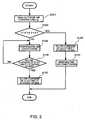
- FIG. 2is a flowchart illustrating processes performed by the pre-air-conditioning control unit 16 when the electricity storage device 20 is charged and pre-air conditioning is performed by the external power source 24 before the planned departure time t1 of the vehicle.
- an outdoor air temperature ⁇ g at the present location of the self vehicleis read.
- the outdoor air temperature ⁇ g at this locationcan be acquired from the information acquisition unit 43 of the navigation system 36, for example. Alternatively, the outdoor air temperature can be directly detected by a temperature sensor, not shown.
- step S102it is determined whether the outdoor air temperature ⁇ g is within a set range (whether or not ⁇ 1 ⁇ g ⁇ 2 is established).
- This rangeis set such that the electric power chargeable to the electricity storage device 20 comes to have a predetermined value or greater. If the outdoor air temperature ⁇ g is within the set range (if the determination result at step S102 is YES), the process advances to step S103. In contrast, if the outdoor air temperature ⁇ g is out of the set range (if the determination result at step S102 is NO), the process advances to step S105.
- step S103charging of the electricity storage device 20 by the external power source 24 is allowed, and charging of the electricity storage device 20 is started.
- the pre-air-conditioning operation start time t2is set after a charging start time t3 of the electricity storage device 20.
- Charging of the electricity storage device 20is controlled by the charging control circuit 26.
- step S104operation (pre-air conditioning) of the air conditioner 12 is started such that the vehicle interior temperature ⁇ c becomes the target temperature ⁇ 0 at the planned departure time t1 of the vehicle.
- FIG 3shows an example where a charging completion time t4 of the electricity storage device 20 becomes later than the pre-air-conditioning operation start time t2. In that case, there is a period during which both charging of the electricity storage device 20 and pre-air conditioning are performed in parallel. However, depending on the conditions of the vehicle interior temperature ⁇ c and the target temperature ⁇ 0, the pre-air-conditioning operation start time t2 may be later than the charging completion time t4 of the electricity storage device 20.
- step S105operation (pre-air conditioning) of the air conditioner 12 is started.
- the pre-air-conditioning operation start time t2is set before the charging start time t3 of the electricity storage device 20. If the outdoor air temperature ⁇ g is lower than ⁇ 1, by heating the vehicle interior through pre-air conditioning, the temperature ⁇ b of the electricity storage device 20 installed in the vehicle interior can be raised, so that the electric power chargeable to the electricity storage device 20 can be increased.
- step S106it is determined whether or not charging of the electricity storage device 20 is allowed. For example, if the temperature ⁇ b of the electricity storage device 20 detected by the temperature sensor 21 is within the set range ( ⁇ 1 ⁇ b ⁇ 2 is established), the process advances to step S107, and charging of the electricity storage device 20 is allowed. In contrast, if the temperature ⁇ b of the electricity storage device 20 is out of the set range ( ⁇ 1 ⁇ b ⁇ 2 is not established), the process returns to step S105.
- step S107charging of the electricity storage device 20 by the external power source 24 is allowed, and charging of the electricity storage device 20 is started. Even at this step, as charging of the electricity storage device 20 can be performed with electric power of a predetermined value or larger, the time required for charging the electricity storage device 20 does not increase. If the vehicle interior temperature ⁇ c detected by the temperature sensor 11 deviates from the target temperature ⁇ 0 after charging of the electricity storage device 20 has been started, pre-air conditioning is performed such that the vehicle interior temperature ⁇ c becomes the target temperature ⁇ 0 at the planned departure time t1 of the vehicle, as shown in FIG. 4 .
- the pre-air-conditioning operation start time t2when charging of the electricity storage device 20 by the external power source 24 is performed before the planned departure time t1 of the vehicle, it is determined whether to set the pre-air-conditioning operation start time t2 before or after the charging start time t3 of the electricity storage device 20, based on the outdoor air temperature ⁇ g. As such, the pre-air-conditioning operation start time t2 varies based on the outdoor air temperature ⁇ g.
- the temperature of the electricity storage device 20can be regulated beforehand by the pre-air conditioning before starting charging of the electricity storage device 20, whereby the electric power chargeable to the electricity storage device 20 can be increased.
- the total time required for both charging the electricity storage device 20 and performing pre-air conditioning by the external power source 24can be reduced.
- the electric power chargeable to the electricity storage device 20can be sufficiently secured even if the pre-air-conditioning operation start time t2 is set after the charging start time t3 of the electricity storage device 20.
- the time required for charging the electricity storage device 20does not increase.
- a pre-air conditioning period for causing the vehicle interior temperature ⁇ c to be the target temperature ⁇ 0can be sufficiently secured, whereby pre-air conditioning can be performed more appropriately.
- the temperature ⁇ b of the electricity storage device 20 detected by the temperature sensor 11may be used instead of the outdoor air temperature ⁇ g.
- the pre-air-conditioning operation start time t2can be varied based on the outdoor air temperature ⁇ g by determining whether to set the pre-air-conditioning operation start time t2 before or after the charging start time t3 of the electricity storage device 20 based on the temperature ⁇ b of the electricity storage device 20.
- the pre-air-conditioning operation start time t2can be set before the charging start time t3 of the electricity storage device 20, and when the temperature ⁇ b of the electricity storage device 20 is within the set range, the pre-air-conditioning operation start time t2 can be set after the charging start time t3 of the electricity storage device 20. Even in this case, the total time required for both charging the electricity storage device 20 and performing pre-air conditioning by the external power source 24 can be reduced.
- charging of the electricity storage device 20is not started when pre-air conditioning is performed at step S105 in the flowchart shown in FIG. 2 .
- charging of the electricity storage device 20can be performed while limiting the electric power to be charged.
- a limit value of the electric power to be charged in that casemay be set based on the temperature ⁇ b of the electricity storage device 20. In such a case, the limitation of the electric power to be charged to the electricity storage device 20 is released when the temperature ⁇ b of the electricity storage device 20 comes into the set range, for example.
- inputs including a request forperformingpre-air conditioning, the planned departure time t1 of the vehicle, and the target temperature ⁇ 0 inside the vehicle interiorare received by means of the operation input receiving unit 44 of the navigation system 36.
- inputs including a request for performing pre-air conditioning, the planned departure time t1 of the vehicle, and the target temperature ⁇ 0 inside the vehicle interiormay be received by means of another operation input receiving unit provided separately from the navigation system 36 (e.g., air-conditioning control panel).
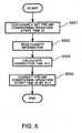
- FIG. 5is a flowchart illustrating processes performed by an air-conditioning control device according to a second embodiment of the present invention. As the configuration of a vehicle having the air-conditioning control device according to the second embodiment is the same as that of the first embodiment, the description is not repeated.
- the pre-air-conditioning start time t2is temporarily set based on the planned departure time t1 and the target temperature ⁇ 0 from the operation input receiving unit 44.
- climate informationis read.
- This climate informationincludes weather, an outdoor air temperature ⁇ g, and an outdoor air humidity hg, which can be acquired from the information acquiring unit 43 of the navigation system 36.
- a correction time ⁇ t1 for the pre-air-conditioning operation start time t2is calculated based on the climate information read at step S202.
- the pre-air-conditioning operation start time t2is corrected by the correction time ⁇ t1 calculated at step S203.
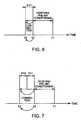
- FIG. 6shows an example of correcting the pre-air-conditioning operation start time t2 in an advancing direction.
- the correction time ⁇ t1is determined so as to make the pre-air-conditioning operation start time t2 earlier than the time temporarily set at step S201.
- the correction time ⁇ t1is determined so as to make the pre-air-conditioning operation start time t2 later than the time temporarily set at step S201.
- the correction time ⁇ t1is determined so as to make the pre-air-conditioning operation start time t2 later than the time temporarily set at step S201.
- the correction time ⁇ t1is determined so as to make the pre-air-conditioning operation start time t2 earlier than the time temporarily set at step S201.
- the vehicle interior temperature ⁇ cis not easily raised when the outdoor air temperature ⁇ g is low and the vehicle interior temperature ⁇ c is not easily dropped when the outdoor air temperature ⁇ g is high, the vehicle interior temperature ⁇ c can be made a proper temperature at the planned departure time t1by correcting the pre-air-conditioning operation start time t2 based on the outdoor air temperature ⁇ g.
- the correction time ⁇ t1is determined so as to make the pre-air-conditioning operation start time t2 earlier than the time temporarily set at step S201.
- the correction time ⁇ t1is determined so as to make the pre-air-conditioning operation start time t2 later than the time temporarily set at step S201.
- the correction time ⁇ t1is determined so as to make the pre-air-conditioning operation start time t2 later than the time temporarily set at step S201.
- the correction time ⁇ t1is determined so as to make the pre-air-conditioning operation start time t2 earlier than the time temporarily set at step S201.
- the correction time ⁇ t1is determined so as to make the pre-air-conditioning operation start time t2 later than the time temporarily set at step S201.
- the correction time ⁇ t1is determined so as to make the pre-air-conditioning operation start time t2 earlier than the time temporarily set at step S201.
- the correction time ⁇ t1is determined so as to make the pre-air-conditioning operation start time t2 earlier than the time temporarily set at step 5201.
- the correction time ⁇ t1is determined so as to make the pre-air-conditioning operation start time t2 later than the time temporarily set at step S201.
- the correction time ⁇ t1may be determined based on a combination of two or more of the outdoor air temperature ⁇ g, the outdoor air humidity hg, and the weather.
- the vehicle interior temperature ⁇ c at the planned departure time t1can be made a proper temperature by adapting to the climate conditions at the place where the vehicle locates. As such, pre-air conditioning can be performed more appropriately.
- a correction time ⁇ t2(to change the pre-air-conditioning operation start time t2) based on the number of planned occupants of the vehicle.
- the operation input receiving unit 44can receive an input of the number of planned occupants of the vehicle made by the operator.
- the correction time ⁇ t2may be determined so as to make the pre-air-conditioning operation start time t2 later than the time temporarily set at step S201.
- the correction time ⁇ t2may be determined so as to make the pre-air-conditioning operation start time t2 earlier than the time temporarily set at step S201.
- the correction time ⁇ t2may be determined so as to make the pre-air-conditioning operation start time t2 earlier than the time temporarily set at step S201.
- the correction time ⁇ t2may be determined so as to make the pre-air-conditioning operation start time t2 later than the time temporarily set at step S201. Further, as shown in FIG. 7 , the pre-air-conditioning operation start time t2 may be corrected by the correction time ⁇ t1+ ⁇ t2.
- FIG. 7shows an example of correcting the pre-air-conditioning operation start time t2 in an advancing direction.
- the vehicle interior temperature ⁇ cis subject to rising as the number of occupants in the vehicle increases, the vehicle interior temperature ⁇ c can be made a proper temperature corresponding to the number of occupants of the vehicle by changing the pre-air-conditioning operation start time t2 according to the number of planned occupants of the vehicle. As such, pre-air conditioning can be performed more appropriately.
Landscapes
- Engineering & Computer Science (AREA)
- Mechanical Engineering (AREA)
- Physics & Mathematics (AREA)
- Thermal Sciences (AREA)
- Chemical & Material Sciences (AREA)
- Manufacturing & Machinery (AREA)
- Chemical Kinetics & Catalysis (AREA)
- Electrochemistry (AREA)
- General Chemical & Material Sciences (AREA)
- Power Engineering (AREA)
- Transportation (AREA)
- Radar, Positioning & Navigation (AREA)
- Remote Sensing (AREA)
- Combustion & Propulsion (AREA)
- Life Sciences & Earth Sciences (AREA)
- Sustainable Development (AREA)
- Sustainable Energy (AREA)
- Electric Propulsion And Braking For Vehicles (AREA)
- Air-Conditioning For Vehicles (AREA)
- Secondary Cells (AREA)
Description
- The present invention relates to an air conditioning control device for a vehicle. In particular, the present invention relates to an air conditioning control device for a vehicle, which brings an air conditioner into operation before planned departure time of the vehicle, or performs so-called pre-air conditioning.
- In a vehicle capable of traveling by electric power supplied from an electricity storage device to an electric motor (e.g., plug-in hybrid vehicle or electric automobile),an air conditioning control device for performing pre-air conditioning has been proposed, in which operation of an air conditioner is started before planned departure time of the vehicle in order to make the temperature of the vehicle interior appropriate when occupants get in the vehicle (for example, see
JP 2001-63347 A JP 2001-63347 A - In
JP 2001-63347 A - Further, as electric power that can be charged into the electricity storage device decreases when the temperature is low or high, if the electricity storage device has been charged by an external power source before pre-air conditioning is performed when the temperature is low or high, the time required for charging the electricity storage device increases, whereby the total time required for charging the electricity storage device and pre-air conditioning becomes longer. Consequently, there is a case where a sufficient time for pre-air conditioning cannot be secured, so that pre-air conditioning may not be properly performed.
- An other known air conditioning control device is known from
US 5 555 737 , which is considered as the closest prior art. - The present invention is directed to providing an air conditioning control device for a vehicle, which is capable of performing pre-air conditioning more appropriately by starting operation of an air conditioner before planned departure time of the vehicle.
- An air conditioning control device for a vehicle, according to the present invention, is disclosed in claims 1-11, as well as a corresponding vehicle, disclosed in
claim 12. FIG. 1 is a diagram showing the schematic configuration of a vehicle having an air-conditioning control device according to a first embodiment of the present invention.FIG. 2 is a flowchart illustrating processes performed by the air-conditioning control device according to the first embodiment of the present invention.FIG. 3 is a diagram illustrating processes performed by the air-conditioning control device according to the first embodiment of the present invention.FIG. 4 is a diagram illustrating processes performed by the air-conditioning control device according to the first embodiment of the present invention.FIG. 5 is.a flowchart illustrating processes performed by an air-conditioning control device according to a second embodiment of the present invention.FIG. 6 is a diagram illustrating processes performed by the air-conditioning control device according to the second embodiment of the present invention.FIG. 7 is a diagram illustrating other processes performed by the air-conditioning control device according to the second embodiment of the present invention.- Hereinafter, preferable embodiments of the present invention will be described in accordance with the drawings.
FIG. 1 is a diagram showing the schematic configuration of a vehicle having an air-conditioning control device according to a first embodiment of the present invention. The vehicle of the present embodiment is a plug-in hybrid vehicle or an electric automobile capable of traveling by electric power supplied from anelectricity storage device 20 to anelectric motor 23 for driving the vehicle. The vehicle of the present embodiment is provided with theelectricity storage device 20, anavigation system 36, anair conditioner 12, and an air-conditioning control unit 14, to be described below.- The
electricity storage device 20, which is chargeable and dischargeable, is constituted of a secondary battery such as a lithium-ion battery and stores electrical energy. Theelectricity storage device 20 of the present embodiment is installed in the vehicle interior, together with atemperature sensor 21 for detecting temperature τb of theelectricity storage device 20. DC power from the electricity storage device (secondary battery) 20 is converted to AC power by aninverter 25 for example, and then supplied to theelectric motor 23 for driving the vehicle, whereby the power is converted to the power of theelectric motor 23 and used for travel of the vehicle. As the vehicle has anattachment plug 22 for charging, theelectricity storage device 20 can be charged by connecting anexternal power source 24 to theattachment plug 22. When theelectricity storage device 20 is charged by theexternal power source 24, acharging control circuit 26 controls charging of theelectricity storage device 20. - The
navigation system 36 includes amap database 41, a self-vehicleposition detecting unit 42, aninformation acquisition unit 43, an operationinput receiving unit 44, anavigation control unit 45, and adisplay 46. Although thenavigation system 36 is operable by electric power from theelectricity storage device 20, when theexternal power source 24 is connected to theattachment plug 22, thenavigation system 36 is also operable by electric power from theexternal power source 24. - The
map database 41 stores road map data. The self-vehicleposition detecting unit 42 detects the present location of the self vehicle using a GPS for example, and outputs a signal indicating the present location of the self vehicle to thenavigation control unit 45. Theinformation acquisition unit 43 receives traffic information such as traffic jam information and regulation information from the outside via communications using VICS (registered trademark) for example, and output signals indicating the traffic information to thenavigation control unit 45. Theinformation acquisition unit 43 is also able to receive climate information including at least one of weather, outdoor air temperature and outdoor air humidity via communication with the outside of the vehicle. The operationinput receiving unit 44 receives inputs by the operator including the destination of the vehicle, setting of display/non-display of guide routes, and setting of display/non-display of traffic information, and outputs signals indicating those inputs to thenavigation control unit 45. - The
navigation control unit 45 displays the present location of the self vehicle detected by the self-vehicleposition detection unit 42 and a road map around the present location of the self vehicle read out from themap database 41, on thedisplay 46. If it is set to display a guide route, thenavigation control unit 45 displays a guide route over the road map on thedisplay 46, and if it is set to display traffic information, thenavigation control unit 45 displays traffic information over the road map on thedisplay 46. - The air conditioner (air conditioning device) 12 conditions air inside the vehicle interior. The vehicle interior has a
temperature sensor 11 for detecting the vehicle interior temperature τc. Although theair conditioner 12 is operable by electric power from theelectricity storage device 20, when theexternal power source 24 is connected to theattachment plug 22, theair conditioner 12 is also operable by electric power from theexternal power source 24. The air-conditioning control unit 14 controls theair conditioner 12. In the present embodiment, the air-conditioning control unit 14 includes a pre-air-conditioning control unit 16 for performing pre-air conditioning, that is, allowing theair conditioner 12 to start operation at an air-conditioning operation start time t2 before a planned departure time (boarding time) t1 of the vehicle such that the vehicle interior temperature τc becomes a target temperature τ0 at the planned departure time t1. When performing the pre-air conditioning, the operationinput receiving unit 44 can receive inputs, by the operator, of a request for performing pre-air conditioning, the planned departure time t1 of the vehicle, and the target temperature τ0 of the vehicle interior, and output signals indicating those inputs to the pre-air-conditioning control unit 16. Upon receiving the request for performing pre-air conditioning from the operationinput receiving unit 44, the pre-air-conditioning control unit 16 determines an air-conditioning operation start time t2 necessary for causing the vehicle interior temperature τc to be the target temperature τ0 at the planned departure time t1 based on the planned departure time t1 and the target temperature τ0, and controls theair conditioner 12 after the operation has been started. For example, if the vehicle interior temperature τc detected by thetemperature sensor 11 is lower than the target temperature τ0, the vehicle interior is heated such that the vehicle interior temperature τc rises. In contrast, if the vehicle interior temperature τc detected by thetemperature sensor 11 is higher than the target temperature τ0, the vehicle interior is cooled so that the vehicle interior temperature τc drops. Further, when performing pre-air conditioning, it is also possible to control theair conditioner 12 such that vehicle interior humidity hc (for example, detected by a humidity sensor not shown) becomes target humidity h0 at the planned departure time t1. In a state where theexternal power source 24 is connected to theattachment plug 22, pre-air conditioning may be performed using electric power from theexternal power source 24. - In the case of performing both charging of the electricity storage device (secondary battery) 20 and pre-air conditioning by the
external power source 24 before the planned departure time t1 of the vehicle, if theelectricity storage device 20 is charged first, the electric power chargeable to theelectricity storage device 20 decreases in the case of a low temperature, so that the time taken for charging theelectricity storage device 20 increases. As a result, the total time required for both charging theelectricity storage device 20 and performing pre-air conditioning increases. Even in the case of a high temperature, as the electric power chargeable to theelectricity storage device 20 decreases, the time taken for charging theelectricity storage device 20 increases. As a result, the total time required for both charging theelectricity storage device 20 and performing pre-air conditioning increases. As such, in the present embodiment, pre-air conditioning is performed before starting charging of theelectricity storage device 20 in the case of a low temperature or a high temperature so as to control the temperature of theelectricity storage device 20 installed in the vehicle interior. Thereby, a decrease in the electric power chargeable to theelectricity storage device 20 is prevented. FIG. 2 is a flowchart illustrating processes performed by the pre-air-conditioning control unit 16 when theelectricity storage device 20 is charged and pre-air conditioning is performed by theexternal power source 24 before the planned departure time t1 of the vehicle. First, at step S101, an outdoor air temperature τg at the present location of the self vehicle is read. The outdoor air temperature τg at this location can be acquired from theinformation acquisition unit 43 of thenavigation system 36, for example. Alternatively, the outdoor air temperature can be directly detected by a temperature sensor, not shown. Next, at step S102, it is determined whether the outdoor air temperature τg is within a set range (whether or not τ1≤τg≤τ2 is established). This range is set such that the electric power chargeable to theelectricity storage device 20 comes to have a predetermined value or greater. If the outdoor air temperature τg is within the set range (if the determination result at step S102 is YES), the process advances to step S103. In contrast, if the outdoor air temperature τg is out of the set range (if the determination result at step S102 is NO), the process advances to step S105.- At step S103, charging of the
electricity storage device 20 by theexternal power source 24 is allowed, and charging of theelectricity storage device 20 is started. This means, as shown inFIG. 3 , that the pre-air-conditioning operation start time t2 is set after a charging start time t3 of theelectricity storage device 20. Charging of theelectricity storage device 20 is controlled by the chargingcontrol circuit 26. At this step, as theelectricity storage device 20 can be charged with electric power of a predetermined value or larger, the time required for charging theelectricity storage device 20 does not increase. Then, at step S104, operation (pre-air conditioning) of theair conditioner 12 is started such that the vehicle interior temperature τc becomes the target temperature τ0 at the planned departure time t1 of the vehicle.FIG. 3 shows an example where a charging completion time t4 of theelectricity storage device 20 becomes later than the pre-air-conditioning operation start time t2. In that case, there is a period during which both charging of theelectricity storage device 20 and pre-air conditioning are performed in parallel. However, depending on the conditions of the vehicle interior temperature τc and the target temperature τ0, the pre-air-conditioning operation start time t2 may be later than the charging completion time t4 of theelectricity storage device 20. - On the other hand, at step S105, operation (pre-air conditioning) of the
air conditioner 12 is started. This means, as shown inFIG. 4 , that the pre-air-conditioning operation start time t2 is set before the charging start time t3 of theelectricity storage device 20. If the outdoor air temperature τg is lower than τ1, by heating the vehicle interior through pre-air conditioning, the temperature τb of theelectricity storage device 20 installed in the vehicle interior can be raised, so that the electric power chargeable to theelectricity storage device 20 can be increased. In contrast, if the outdoor air temperature τg is higher than τ 2, by cooling the vehicle interior through pre-air conditioning, the temperature τb of theelectricity storage device 20 installed in the vehicle interior can be lowered, so that the electric power chargeable to theelectricity storage device 20 can be increased. At step S106, it is determined whether or not charging of theelectricity storage device 20 is allowed. For example, if the temperature τb of theelectricity storage device 20 detected by thetemperature sensor 21 is within the set range (τ1≤τb≤τ2 is established), the process advances to step S107, and charging of theelectricity storage device 20 is allowed. In contrast, if the temperature τb of theelectricity storage device 20 is out of the set range (τ1≤τb≤τ2 is not established), the process returns to step S105. - At step S107, charging of the
electricity storage device 20 by theexternal power source 24 is allowed, and charging of theelectricity storage device 20 is started. Even at this step, as charging of theelectricity storage device 20 can be performed with electric power of a predetermined value or larger, the time required for charging theelectricity storage device 20 does not increase. If the vehicle interior temperature τc detected by thetemperature sensor 11 deviates from the target temperature τ0 after charging of theelectricity storage device 20 has been started, pre-air conditioning is performed such that the vehicle interior temperature τc becomes the target temperature τ0 at the planned departure time t1 of the vehicle, as shown inFIG. 4 . - As described above, in the present embodiment, when charging of the
electricity storage device 20 by theexternal power source 24 is performed before the planned departure time t1 of the vehicle, it is determined whether to set the pre-air-conditioning operation start time t2 before or after the charging start time t3 of theelectricity storage device 20, based on the outdoor air temperature τg. As such, the pre-air-conditioning operation start time t2 varies based on the outdoor air temperature τg. When the outdoor air temperature τg is out of the set range, by setting the pre-air-conditioning operation start time t2 before the charging start time t3 of theelectricity storage device 20, the temperature of theelectricity storage device 20 can be regulated beforehand by the pre-air conditioning before starting charging of theelectricity storage device 20, whereby the electric power chargeable to theelectricity storage device 20 can be increased. As a result, the total time required for both charging theelectricity storage device 20 and performing pre-air conditioning by the external power source 24can be reduced. In contrast, when the outdoor air temperature τg is within the set range, the electric power chargeable to theelectricity storage device 20 can be sufficiently secured even if the pre-air-conditioning operation start time t2 is set after the charging start time t3 of theelectricity storage device 20. As such, the time required for charging theelectricity storage device 20 does not increase. As described above, according to the present embodiment, as the total time required for both charging theelectricity storage device 20 and performing pre-air conditioning by theexternal power source 24 can be reduced, a pre-air conditioning period for causing the vehicle interior temperature τc to be the target temperature τ0 can be sufficiently secured, whereby pre-air conditioning can be performed more appropriately. - In the processes in the flowchart shown in
FIG. 2 , the temperature τb of theelectricity storage device 20 detected by thetemperature sensor 11 may be used instead of the outdoor air temperature τg. This means, in the case of charging theelectricity storage device 20 by theexternal power source 24 before the planned departure time t1 of the vehicle, the pre-air-conditioning operation start time t2 can be varied based on the outdoor air temperature τg by determining whether to set the pre-air-conditioning operation start time t2 before or after the charging start time t3 of theelectricity storage device 20 based on the temperature τb of theelectricity storage device 20. In that case, when the temperature τb of theelectricity storage device 20 is out of the set range, the pre-air-conditioning operation start time t2 can be set before the charging start time t3 of theelectricity storage device 20, and when the temperature τb of theelectricity storage device 20 is within the set range, the pre-air-conditioning operation start time t2 can be set after the charging start time t3 of theelectricity storage device 20. Even in this case, the total time required for both charging theelectricity storage device 20 and performing pre-air conditioning by theexternal power source 24 can be reduced. - In the above description, it has been described that charging of the
electricity storage device 20 is not started when pre-air conditioning is performed at step S105 in the flowchart shown inFIG. 2 . However, in the present embodiment, when pre-air conditioning is performed at step S105, charging of theelectricity storage device 20 can be performed while limiting the electric power to be charged. A limit value of the electric power to be charged in that case may be set based on the temperature τb of theelectricity storage device 20. In such a case, the limitation of the electric power to be charged to theelectricity storage device 20 is released when the temperature τb of theelectricity storage device 20 comes into the set range, for example. - Further, in the above description, it has also been described that inputs including a request forperformingpre-air conditioning, the planned departure time t1 of the vehicle, and the target temperature τ0 inside the vehicle interior are received by means of the operation
input receiving unit 44 of thenavigation system 36. However, in the present embodiment, inputs including a request for performing pre-air conditioning, the planned departure time t1 of the vehicle, and the target temperature τ0 inside the vehicle interior may be received by means of another operation input receiving unit provided separately from the navigation system 36 (e.g., air-conditioning control panel). FIG. 5 is a flowchart illustrating processes performed by an air-conditioning control device according to a second embodiment of the present invention. As the configuration of a vehicle having the air-conditioning control device according to the second embodiment is the same as that of the first embodiment, the description is not repeated.- First, at step S201, the pre-air-conditioning start time t2 is temporarily set based on the planned departure time t1 and the target temperature τ0 from the operation
input receiving unit 44. Then, at step S202, climate information is read. This climate information includes weather, an outdoor air temperature τg, and an outdoor air humidity hg, which can be acquired from theinformation acquiring unit 43 of thenavigation system 36. - Next, at step S203, a correction time δt1 for the pre-air-conditioning operation start time t2 is calculated based on the climate information read at step S202. At step S204, the pre-air-conditioning operation start time t2 is corrected by the correction time δt1 calculated at step S203.
FIG. 6 shows an example of correcting the pre-air-conditioning operation start time t2 in an advancing direction. In an example of calculating the correction time δt1 based on the outdoor air temperature τg, when the vehicle interior temperature τc is lower than the target temperature τ0 and the vehicle interior is to be heated by pre-air conditioning, if the outdoor air temperature τg at the present location of the self vehicle is lower than the set temperature, the correction time δt1 is determined so as to make the pre-air-conditioning operation start time t2 earlier than the time temporarily set at step S201. In contrast, in the case of heating the vehicle interior, if the outdoor air temperature τg at the present location of the self vehicle is higher than the set temperature, the correction time δt1 is determined so as to make the pre-air-conditioning operation start time t2 later than the time temporarily set at step S201. Further, when the vehicle interior temperature τc is higher than the target temperature τ0 and the vehicle interior is to be cooled by pre-air conditioning, if the outdoor air temperature τg at the present location of the self vehicle is lower than the set temperature, the correction time δt1 is determined so as to make the pre-air-conditioning operation start time t2 later than the time temporarily set at step S201. In contrast, in the case of cooling the vehicle interior, if the outdoor air temperature τg at the present location of the self vehicle is higher than the set temperature, the correction time δt1 is determined so as to make the pre-air-conditioning operation start time t2 earlier than the time temporarily set at step S201. Although the vehicle interior temperature τc is not easily raised when the outdoor air temperature τg is low and the vehicle interior temperature τc is not easily dropped when the outdoor air temperature τg is high, the vehicle interior temperature τc can be made a proper temperature at the planned departure time t1by correcting the pre-air-conditioning operation start time t2 based on the outdoor air temperature τg. - Further, in an example of calculating the correction time δt1 based on the outdoor air humidity hg, in the case of heating the vehicle interior by pre-air conditioning, if the outdoor air humidity hg is lower than the set humidity, the correction time δt1 is determined so as to make the pre-air-conditioning operation start time t2 earlier than the time temporarily set at step S201. In contrast, in the case of heating the vehicle interior, if the outdoor air humidity hg is higher than the set humidity, the correction time δt1 is determined so as to make the pre-air-conditioning operation start time t2 later than the time temporarily set at step S201. Further, in the case of cooling the vehicle interior by pre-air conditioning, if the outdoor air humidity hg is lower than the set humidity, the correction time δt1 is determined so as to make the pre-air-conditioning operation start time t2 later than the time temporarily set at step S201. In contrast, in the case of cooling the vehicle interior by pre-air conditioning, if the outdoor air humidity hg is higher than the set humidity, the correction time δt1 is determined so as to make the pre-air-conditioning operation start time t2 earlier than the time temporarily set at step S201.
- Further, in an example of calculating the correction time δt1 based on the weather, in the case of heating the vehicle interior by pre-air conditioning, if the weather at the present location of the self vehicle is fine, the correction time δt1 is determined so as to make the pre-air-conditioning operation start time t2 later than the time temporarily set at step S201. In contrast, in the case of heating the vehicle interior by pre-air conditioning, if the weather at the present location of the self vehicle is rainy or snowy, the correction time δt1 is determined so as to make the pre-air-conditioning operation start time t2 earlier than the time temporarily set at step S201. Further, in the case of cooling the vehicle interior by pre-air conditioning, if the weather at the present location of the self vehicle is fine, the correction time δt1 is determined so as to make the pre-air-conditioning operation start time t2 earlier than the time temporarily set at step 5201. In contrast, in the case of cooling the vehicle interior by pre-air conditioning, if the weather at the present location of the self vehicle is rainy or snowy, the correction time δt1 is determined so as to make the pre-air-conditioning operation start time t2 later than the time temporarily set at step S201. The correction time δt1 may be determined based on a combination of two or more of the outdoor air temperature τg, the outdoor air humidity hg, and the weather.
- As described above, in the present embodiment, by changing the pre-air-conditioning operation start time t2 based on climate information such as an outdoor air temperature, an outdoor air humidity hg, and weather, the vehicle interior temperature τc at the planned departure time t1 can be made a proper temperature by adapting to the climate conditions at the place where the vehicle locates. As such, pre-air conditioning can be performed more appropriately.
- In the present embodiment, it is also possible to calculate a correction time δt2 (to change the pre-air-conditioning operation start time t2) based on the number of planned occupants of the vehicle. In that case, the operation
input receiving unit 44 can receive an input of the number of planned occupants of the vehicle made by the operator. In the case of heating the vehicle interior by pre-air conditioning, if the number of planned occupants is larger than the predetermined number, the correction time δt2 may be determined so as to make the pre-air-conditioning operation start time t2 later than the time temporarily set at step S201. In contrast, in the case of heating the vehicle interior by pre-air conditioning, if the number of planned occupants is smaller than the predetermined number, the correction time δt2 may be determined so as to make the pre-air-conditioning operation start time t2 earlier than the time temporarily set at step S201. On the other hand, in the case of cooling the vehicle interior by pre-air conditioning, if the number of planned occupants is larger than the predetermined number, the correction time δt2 may be determined so as to make the pre-air-conditioning operation start time t2 earlier than the time temporarily set at step S201. In contrast, in the case of cooling the vehicle interior by pre-air conditioning, if the number of planned occupants is smaller than the predetermined number, the correction time δt2 may be determined so as to make the pre-air-conditioning operation start time t2 later than the time temporarily set at step S201. Further, as shown inFIG. 7 , the pre-air-conditioning operation start time t2 may be corrected by the correction time δt1+δt2.FIG. 7 shows an example of correcting the pre-air-conditioning operation start time t2 in an advancing direction. Although the vehicle interior temperature τc is subject to rising as the number of occupants in the vehicle increases, the vehicle interior temperature τc can be made a proper temperature corresponding to the number of occupants of the vehicle by changing the pre-air-conditioning operation start time t2 according to the number of planned occupants of the vehicle. As such, pre-air conditioning can be performed more appropriately. - While the present invention has been described with reference to the embodiments, the present invention is not limited to these embodiments. It is understood that various changes may be made therein without departing from the scope of the present invention as defined by the claims.
Claims (12)
- An air conditioning control device for a vehicle, comprising:an air conditioner for conditioning air in a vehicle interior;an input receiving unit for receiving inputs of a planned departure time of the vehicle and a target temperature of the vehicle interior;a pre-air-conditioning control unit for starting operation of the air conditioner at an air conditioning operation start time before the planned departure time so that a temperature in the vehicle interior at the planned departure time becomes the target temperature; andan outdoor air temperature acquisition unit for acquiring an outdoor air temperature, whereinthe pre-air-conditioning control unit changes the air conditioning operation start time based on the outdoor air temperature acquired by the outdoor air temperature acquisition unit,the air conditioner conditions the air in the vehicle interior where an electricity storage device chargeable by an external power source is installed,characterized in thatwhen the electricity storage device is charged by the external power source before the planned departure time, the pre-air-conditioning control unit determines to set the air conditioning operation start time earlier or later than a charging start time of the electricity storage device, based on the outdoor air temperature acquired by the outdoor air temperature acquisition unit.
- The air conditioning control device for the vehicle, according to Claim 1, wherein
when the electricity storage device is charged by the external power source before the planned departure time, if the outdoor air temperature acquired by the outdoor air temperature acquisition unit is out of a set range, the pre-air-conditioning control unit sets the air conditioning operation start time earlier than the charging start time of the electricity storage device. - The air conditioning control device for the vehicle, according to Claim 1, wherein
when the electricity storage device is charged by the external power source before the planned departure time, if the outdoor air temperature acquired by the outdoor air temperature acquisition unit is within a set range, the pre-air-conditioning control unit sets the air conditioning operation start time later than the charging start time oF the electricity storage device. - An air conditioning control device for a vehicle, comprising:an air conditioner for conditioning air in a vehicle interior;an input receiving unit for receiving inputs of a planned departure time of the vehicle and a target temperature of the vehicle interior;a pre-air-conditioning control unit for performing pre-air conditioning to start operation of the air conditioner at an air conditioning operation start time before the planned departure time so that a temperature in the vehicle interior at the planned departure time becomes the target temperature;andan outdoor air temperature acquisition unit for acquiring an outdoor air temperature, whereinthe air conditioner conditions the air in the vehicle interior where an electricity storage device chargeable by an external power source is installed,characterized in thatthe pre-air-conditioning control unit is capable of regulating a temperature of the electricity storage device by performing the pre-air conditioning, and changes the air conditioning operation start time based on the outdoor air temperature acquired by the outdoor air temperature acquisition unit.
- The air conditioning control device for the vehicle, according to Claim 4, wherein
when the electricity storage device is charged by the external power source before the planned departure time, the pre-air-conditioning control unit changes the air conditioning operation start time based on the outdoor air temperature acquired by the outdoor air temperature acquisition unit. - The air conditioning control device for the vehicle, according to Claim 5, wherein
when the electricity storage device is charged by the external power source before the planned departure time, if the outdoor air temperature acquired by the outdoor air temperature acquisition unit is out of a set range, the pre-air-conditioning control unit sets the air conditioning operation start time earlier than the charging start time of the electricity storage device. - The air conditioning control device for the vehicle, according to Claim 5, wherein
when the electricity storage device is charged by the external power source before the planned departure time, if the outdoor air temperature acquired by the outdoor air temperature acquisition unit is within a set range, the pre-air-conditioning control unit sets the air conditioning operation start time later than the charging start time of the electricity storage device. - An air conditioning control device for a vehicle, comprising:an air conditioner for conditioning air in a vehicle interior;an input receiving unit for receiving inputs of a planned departure time of the vehicle and a target temperature of the vehicle interior; anda pre-air-conditioning control unit for starting operation of the air conditioner at an air conditioning operation start time before the planned departure time so that a temperature in the vehicle interior at the planned departure time becomes the target temperature, whereinthe air conditioner is operable by an external power source capable of charging an electricity storage device installed in the vehicle interior, and the air conditioning control device comprises an electricity storage device temperature acquisition unit for acquiring a temperature of the electricity storage device,characterized in thatwhen the electricity storage device is charged by the external power source before the planned departure time, the pre-air-conditioning control unit changes the air conditioning operation start time based on the temperature of the electricity storage device acquired by the electricity storage device temperature acquisition unit.
- The air conditioning control device for the vehicle, according to Claim 8, wherein
when the electricity storage device is charged by the external power source before the planned departure time, the pre-air-conditioning control unit determines to set the air conditioning operation start time earlier or later than a charging start time of the electricity storage device, based on the temperature of the electricity storage device acquired by the electricity storage device temperature acquisition unit. - The air conditioning control device for the vehicle, according to Claim 9, wherein
when the electricity storage device is charged by the external power source before the planned departure time, if the temperature of the electricity storage device acquired by the electricity storage device temperature acquisition unit is out of a set range, the pre-air-conditioning control unit sets the air conditioning operation start time earlier than the charging start time of the electricity storage device. - The air conditioning control device for the vehicle, according to Claim 9, wherein
when the electricity storage device is charged by the external power source before the planned departure time, if the temperature of the electricity storage device acquired by the electricity storage device temperature acquisition unit is within a set range, the pre-air-conditioning control unit sets the air conditioning operation start time later than the charging start time of the electricity storage device. - A vehicle, comprising the air conditioning control device according to any one of Claims 1 to 11, and capable of traveling by means of electric power supplied from an electricity storage device to an electric motor.
Applications Claiming Priority (2)
| Application Number | Priority Date | Filing Date | Title |
|---|---|---|---|
| JP2007160179AJP4353283B2 (en) | 2007-06-18 | 2007-06-18 | Vehicle air conditioning control device |
| PCT/JP2008/059609WO2008155977A1 (en) | 2007-06-18 | 2008-05-20 | Air conditioning control device for vehicle |
Publications (3)
| Publication Number | Publication Date |
|---|---|
| EP2163413A1 EP2163413A1 (en) | 2010-03-17 |
| EP2163413A4 EP2163413A4 (en) | 2011-10-26 |
| EP2163413B1true EP2163413B1 (en) | 2012-10-24 |
Family
ID=40156136
Family Applications (1)
| Application Number | Title | Priority Date | Filing Date |
|---|---|---|---|
| EP08753116AActiveEP2163413B1 (en) | 2007-06-18 | 2008-05-20 | Air conditioning control device for vehicle |
Country Status (6)
| Country | Link |
|---|---|
| US (1) | US8341971B2 (en) |
| EP (1) | EP2163413B1 (en) |
| JP (1) | JP4353283B2 (en) |
| CN (1) | CN101687457B (en) |
| ES (1) | ES2397485T3 (en) |
| WO (1) | WO2008155977A1 (en) |
Cited By (1)
| Publication number | Priority date | Publication date | Assignee | Title |
|---|---|---|---|---|
| EP4438391A4 (en)* | 2021-11-25 | 2025-03-26 | Beijing Co Wheels Technology Co., Ltd | VEHICLE CHARGING CONTROL METHOD AND APPARATUS, DEVICE, AND STORAGE MEDIUM |
Families Citing this family (63)
| Publication number | Priority date | Publication date | Assignee | Title |
|---|---|---|---|---|
| US8118237B2 (en)* | 2009-02-16 | 2012-02-21 | General Electric Company | System and method for vehicle temperature control |
| JP2011088600A (en)* | 2009-10-26 | 2011-05-06 | Denso Corp | Air conditioner for vehicle |
| US9002568B2 (en)* | 2009-12-17 | 2015-04-07 | GM Global Technology Operations LLC | Method for conditioning one or more aspects of a vehicle |
| JP5399333B2 (en)* | 2010-07-01 | 2014-01-29 | トヨタ自動車株式会社 | Pre air conditioning system |
| JP5505236B2 (en)* | 2010-09-30 | 2014-05-28 | 株式会社デンソー | Air conditioner for vehicles |
| EP2439088B1 (en)* | 2010-10-04 | 2013-04-24 | Harman Becker Automotive Systems GmbH | Energy-efficient controlling of air conditioning system |
| JP5668541B2 (en) | 2011-03-11 | 2015-02-12 | 日産自動車株式会社 | Vehicle charging control device |
| JP5668542B2 (en) | 2011-03-11 | 2015-02-12 | 日産自動車株式会社 | Vehicle charging control device |
| JP5699702B2 (en)* | 2011-03-11 | 2015-04-15 | 日産自動車株式会社 | Vehicle charging control device |
| JP5353974B2 (en)* | 2011-04-18 | 2013-11-27 | 株式会社日本自動車部品総合研究所 | Vehicle power supply |
| CN102958719B (en)* | 2011-05-18 | 2015-04-01 | 丰田自动车株式会社 | Air-condition remote control system for vehicle, server, mobile terminal, and vehicle |
| CN102213228A (en)* | 2011-06-01 | 2011-10-12 | 奇瑞汽车股份有限公司 | Automotive air-conditioning fan control system and control method |
| CN102328566B (en)* | 2011-06-02 | 2013-06-19 | 浙江吉利汽车研究院有限公司 | Air conditioning system for hybrid electric vehicle and control method thereof |
| US20130079978A1 (en)* | 2011-09-22 | 2013-03-28 | Honda Motor Co., Ltd. | Preconditioning a vehicle |
| CN103171398A (en)* | 2011-12-26 | 2013-06-26 | 上海汽车集团股份有限公司 | Control method and controlling device of vehicle air conditioner |
| US9128510B2 (en)* | 2012-04-13 | 2015-09-08 | Toyota Motor Engineering & Manufacturing North America, Inc. | Departure time scheduling control system for an electric vehicle |
| US9537189B2 (en) | 2012-06-11 | 2017-01-03 | Siemens Aktiengesellschaft | Temperature control system for a high-temperature battery or a high-temperature electrolyzer |
| US20140060097A1 (en)* | 2012-08-31 | 2014-03-06 | Philip PERREAULT | Refrigerated truck battery back-up system and related methods |
| JP2014053991A (en)* | 2012-09-05 | 2014-03-20 | Suzuki Motor Corp | Vehicle state alarming device |
| JP6065481B2 (en)* | 2012-09-14 | 2017-01-25 | 日産自動車株式会社 | Air conditioner for vehicles |
| DE102012022590A1 (en)* | 2012-11-20 | 2014-06-05 | Volkswagen Aktiengesellschaft | A method of displaying the condition of a parking heater of a vehicle and parking heater system for a vehicle |
| JP2013224148A (en)* | 2013-07-04 | 2013-10-31 | Mitsubishi Electric Corp | Vehicle equipment control device |
| JP6115419B2 (en) | 2013-09-13 | 2017-04-19 | トヨタ自動車株式会社 | vehicle |
| GB201400573D0 (en)* | 2014-01-14 | 2014-03-05 | Jaguar Land Rover Ltd | Temperature control system for use in a vehicle |
| EP2927030B1 (en) | 2014-04-02 | 2017-10-04 | Volvo Car Corporation | Vehicle ambient air purification arrangement and method, and a vehicle and vehicle fleet comprising such arrangement |
| CN103982985B (en)* | 2014-05-05 | 2016-11-09 | 广东美的制冷设备有限公司 | Air-conditioner operational factor control method and system |
| US20150345958A1 (en)* | 2014-05-27 | 2015-12-03 | Atieva, Inc. | Method of Controlling an Auxiliary Vehicle System |
| US9488980B2 (en)* | 2014-11-25 | 2016-11-08 | Toyota Motor Engineering & Manufacturing North America, Inc. | Smart notification systems for wearable devices |
| JP6375932B2 (en)* | 2014-12-18 | 2018-08-22 | 株式会社デンソー | Air conditioner for vehicles |
| US10220671B2 (en)* | 2015-02-23 | 2019-03-05 | Ford Global Technologies, Llc | Electrified vehicle conditioning using grid power |
| US10059167B2 (en)* | 2015-05-28 | 2018-08-28 | GM Global Technology Operations LLC | Location based remote start |
| DE102015210661A1 (en)* | 2015-06-11 | 2016-12-15 | Robert Bosch Gmbh | Method and device for influencing a climate in the interior of a motor vehicle |
| US9975400B2 (en)* | 2015-06-18 | 2018-05-22 | Ford Global Technologies, Llc | Method of controlling climate in a parked vehicle |
| GB2563514B (en)* | 2016-01-20 | 2020-10-21 | Walmart Apollo Llc | Apparatus and method for refrigeration unit control |
| CN105501157B (en)* | 2016-01-22 | 2017-09-05 | 安徽江淮汽车集团股份有限公司 | A kind of air conditioner of electric vehicle method of supplying power to and system |
| US9914462B2 (en)* | 2016-01-27 | 2018-03-13 | Ford Global Technologies, Llc | Preconditioning electrified vehicle subsystems based on weather forecasts |
| US10196994B2 (en) | 2016-05-16 | 2019-02-05 | Ford Global Technologies, Llc | Powertrain control system |
| US10246073B2 (en) | 2016-05-16 | 2019-04-02 | Ford Global Technologies, Llc | Control system for a hybrid-electric vehicle |
| US9682609B1 (en)* | 2016-06-07 | 2017-06-20 | Ford Global Technologies, Llc | Autonomous vehicle dynamic climate control |
| CN106080101B (en)* | 2016-06-16 | 2018-03-30 | 美的集团武汉制冷设备有限公司 | The control method and mounted air conditioner system of mounted air conditioner system |
| US10759255B2 (en)* | 2016-07-20 | 2020-09-01 | Ford Global Technologies, Llc | Autonomous-vehicle climate-control system |
| CN109863045B (en)* | 2016-10-24 | 2022-09-27 | 沃尔沃卡车集团 | Method for estimating a limit value |
| US10214076B2 (en) | 2016-12-09 | 2019-02-26 | Cummins Inc. | HVAC heating of vehicles and during road emergencies |
| JP6878013B2 (en)* | 2017-01-11 | 2021-05-26 | パイオニア株式会社 | Coordination control system, cooperation control method and computer-readable storage medium |
| KR20180099187A (en)* | 2017-02-28 | 2018-09-05 | 주식회사 가린시스템 | System and method for controlling air conditioner of vehicle |
| CN107089114A (en)* | 2017-04-28 | 2017-08-25 | 北京新能源汽车股份有限公司 | Control method and device of air conditioner |
| US10632818B2 (en)* | 2017-10-13 | 2020-04-28 | Toyota Motor Engineering & Manufacturing North America, Inc. | Mitigating environmental-control load for a hybrid vehicle |
| JP6825537B2 (en)* | 2017-10-23 | 2021-02-03 | トヨタ自動車株式会社 | Pick-up system |
| US11761662B2 (en)* | 2017-12-31 | 2023-09-19 | Universal Electronics Inc. | Method and apparatus for intelligent temperature control |
| JP6914902B2 (en)* | 2018-09-25 | 2021-08-04 | 株式会社日立建機ティエラ | Electric construction machinery |
| CN111137227A (en)* | 2018-11-05 | 2020-05-12 | 上海博泰悦臻网络技术服务有限公司 | Automatic setting method and system for contextual model |
| ES2764048B2 (en)* | 2018-11-30 | 2021-07-07 | Seat Sa | CONDITIONING UNIT |
| ES2764169B2 (en)* | 2018-11-30 | 2022-03-21 | Seat Sa | CONDITIONING PROVISION |
| ES2766098A1 (en)* | 2018-12-11 | 2020-06-11 | Seat Sa | METHOD AND PRE-CLIMATE SYSTEM (Machine-translation by Google Translate, not legally binding) |
| JP6922935B2 (en)* | 2019-01-10 | 2021-08-18 | トヨタ自動車株式会社 | Vehicle air conditioning control system and air conditioning control program |
| JP7077981B2 (en)* | 2019-02-05 | 2022-05-31 | トヨタ自動車株式会社 | Vehicle air conditioner |
| CN111137100A (en)* | 2020-01-03 | 2020-05-12 | 长城汽车股份有限公司 | Method and device for regulating the interior temperature of a vehicle, and vehicle |
| JP7318576B2 (en)* | 2020-03-18 | 2023-08-01 | トヨタ自動車株式会社 | Information processing device, information processing system, program, and vehicle |
| CN111619309B (en)* | 2020-06-01 | 2021-10-26 | 中国第一汽车股份有限公司 | Vehicle control method and device and vehicle control system |
| CN111993856B (en)* | 2020-08-04 | 2022-06-03 | 重庆长安汽车股份有限公司 | Intelligent vehicle cooling and heating control method and system |
| CN112389157B (en)* | 2020-11-20 | 2022-07-01 | 广州橙行智动汽车科技有限公司 | Air conditioner control method and device, vehicle and storage medium |
| US11973348B2 (en)* | 2021-01-12 | 2024-04-30 | Ford Global Technologies, Llc | Grid power dependent preconditioning of vehicle |
| US20230286353A1 (en)* | 2022-03-09 | 2023-09-14 | Daimler Truck North America Llc | Method, system, and technology for preconditioning a vehicle interior |
Family Cites Families (18)
| Publication number | Priority date | Publication date | Assignee | Title |
|---|---|---|---|---|
| JPH0532029A (en) | 1991-07-26 | 1993-02-09 | Koji Abe | Printing device and printing process |
| JP2551830Y2 (en)* | 1991-10-04 | 1997-10-27 | カルソニック株式会社 | car heating system |
| JPH0773906A (en) | 1993-09-06 | 1995-03-17 | Kojima Press Co Ltd | Charger for electric vehicle |
| JPH07212902A (en)* | 1993-12-02 | 1995-08-11 | Nippondenso Co Ltd | Electric car air-conditioner control system |
| JPH07193901A (en)* | 1993-12-28 | 1995-07-28 | Nissan Motor Co Ltd | Air conditioners for electric vehicles |
| JP3222415B2 (en)* | 1997-12-10 | 2001-10-29 | セイコーインスツルメンツ株式会社 | Vehicle air conditioner |
| JP4258876B2 (en)* | 1999-02-17 | 2009-04-30 | マツダ株式会社 | Cooling structure for vehicle battery |
| JP2001063347A (en) | 1999-08-26 | 2001-03-13 | Denso Corp | Vehicular air-conditioning control system |
| JP4164996B2 (en) | 2000-01-05 | 2008-10-15 | 日産自動車株式会社 | Power management system |
| US6745582B1 (en)* | 2003-01-10 | 2004-06-08 | Delphi Technologies, Inc. | HVAC control method for a remote start motor vehicle |
| DE102004004302A1 (en) | 2003-02-03 | 2004-08-12 | Denso Corp., Kariya | Vehicle remote control air conditioning system has a control unit that activates only a ventilation or climate control component of the air conditioning system in order to reduce battery power consumption |
| JP4042699B2 (en)* | 2003-02-03 | 2008-02-06 | 株式会社デンソー | Air conditioner for moving body |
| DE10316106A1 (en)* | 2003-04-09 | 2004-10-21 | Daimlerchrysler Ag | Method and device for stationary air conditioning |
| JP2005255085A (en)* | 2004-03-15 | 2005-09-22 | Sanyo Electric Co Ltd | Air-conditioner for vehicle |
| US7441414B2 (en)* | 2004-10-08 | 2008-10-28 | General Motors Corporation | Method for pre-cooling automotive vehicle passenger compartment |
| CN2818198Y (en)* | 2005-04-19 | 2006-09-20 | 常若福 | Pre-adjuster of vehicle |
| JP4258503B2 (en)* | 2005-08-22 | 2009-04-30 | トヨタ自動車株式会社 | Air conditioner for vehicles |
| US8118237B2 (en)* | 2009-02-16 | 2012-02-21 | General Electric Company | System and method for vehicle temperature control |
- 2007
- 2007-06-18JPJP2007160179Apatent/JP4353283B2/enactiveActive
- 2008
- 2008-05-20CNCN2008800205983Apatent/CN101687457B/enactiveActive
- 2008-05-20ESES08753116Tpatent/ES2397485T3/enactiveActive
- 2008-05-20USUS12/452,023patent/US8341971B2/enactiveActive
- 2008-05-20EPEP08753116Apatent/EP2163413B1/enactiveActive
- 2008-05-20WOPCT/JP2008/059609patent/WO2008155977A1/enactiveApplication Filing
Cited By (1)
| Publication number | Priority date | Publication date | Assignee | Title |
|---|---|---|---|---|
| EP4438391A4 (en)* | 2021-11-25 | 2025-03-26 | Beijing Co Wheels Technology Co., Ltd | VEHICLE CHARGING CONTROL METHOD AND APPARATUS, DEVICE, AND STORAGE MEDIUM |
Also Published As
| Publication number | Publication date |
|---|---|
| JP4353283B2 (en) | 2009-10-28 |
| WO2008155977A1 (en) | 2008-12-24 |
| US8341971B2 (en) | 2013-01-01 |
| CN101687457B (en) | 2011-12-14 |
| ES2397485T3 (en) | 2013-03-07 |
| US20100132388A1 (en) | 2010-06-03 |
| EP2163413A4 (en) | 2011-10-26 |
| JP2008308114A (en) | 2008-12-25 |
| EP2163413A1 (en) | 2010-03-17 |
| CN101687457A (en) | 2010-03-31 |
Similar Documents
| Publication | Publication Date | Title |
|---|---|---|
| EP2163413B1 (en) | Air conditioning control device for vehicle | |
| CN108202608B (en) | Electric vehicle for charging battery, system thereof and battery charging method for electric vehicle | |
| JP6620419B2 (en) | Battery temperature control device and battery temperature control method | |
| US10471844B2 (en) | Electric vehicle and battery charging method of the same | |
| US9020671B2 (en) | Vehicle control using an estimated outside air temperature | |
| JP4228086B1 (en) | vehicle | |
| US8996213B2 (en) | Charge control system for electric motor vehicle | |
| US9751425B2 (en) | Navigation device and cruising range display system | |
| CN111086367A (en) | Air conditioner control device, air conditioner control method, and storage medium | |
| US9122567B2 (en) | User interface system and method | |
| EP2529979A1 (en) | Vehicular battery temperature adjustment device and vehicular battery temperature adjustment method | |
| US9292976B2 (en) | Efficiency gauge for plug-in electric vehicle | |
| US12024058B2 (en) | Method for operating a battery of a parked motor vehicle, and motor vehicle | |
| JP6205799B2 (en) | Vehicle destination arrival estimation device | |
| US20240255299A1 (en) | Electrically powered vehicle and navigation device thereof | |
| JP5083975B2 (en) | Fuel cell vehicle | |
| JP2012078251A (en) | Vehicle navigation device | |
| US20240174123A1 (en) | Control device for vehicle | |
| US20230249584A1 (en) | Charging control system | |
| WO2012132014A1 (en) | Calculation device, calculation system, terminal and calculation method | |
| JP2012005223A (en) | Apparatus for charging of vehicle | |
| JP7196719B2 (en) | Controller for electric vehicle | |
| US20250214486A1 (en) | Control device and vehicle | |
| US20230249576A1 (en) | Charging control device and charging control method | |
| JP2025012275A (en) | vehicle |
Legal Events
| Date | Code | Title | Description |
|---|---|---|---|
| PUAI | Public reference made under article 153(3) epc to a published international application that has entered the european phase | Free format text:ORIGINAL CODE: 0009012 | |
| 17P | Request for examination filed | Effective date:20091223 | |
| AK | Designated contracting states | Kind code of ref document:A1 Designated state(s):AT BE BG CH CY CZ DE DK EE ES FI FR GB GR HR HU IE IS IT LI LT LU LV MC MT NL NO PL PT RO SE SI SK TR | |
| AX | Request for extension of the european patent | Extension state:AL BA MK RS | |
| DAX | Request for extension of the european patent (deleted) | ||
| A4 | Supplementary search report drawn up and despatched | Effective date:20110927 | |
| RIC1 | Information provided on ipc code assigned before grant | Ipc:B60H 1/00 20060101AFI20110921BHEP Ipc:H01M 10/44 20060101ALI20110921BHEP Ipc:H01M 10/50 20060101ALI20110921BHEP Ipc:H01M 10/48 20060101ALI20110921BHEP Ipc:B60H 1/08 20060101ALI20110921BHEP Ipc:B60H 1/32 20060101ALI20110921BHEP | |
| RIC1 | Information provided on ipc code assigned before grant | Ipc:H01M 10/50 20060101ALI20120306BHEP Ipc:H01M 10/48 20060101ALI20120306BHEP Ipc:B60H 1/08 20060101ALI20120306BHEP Ipc:B60H 1/32 20060101ALI20120306BHEP Ipc:B60H 1/00 20060101AFI20120306BHEP Ipc:H01M 10/44 20060101ALI20120306BHEP | |
| GRAP | Despatch of communication of intention to grant a patent | Free format text:ORIGINAL CODE: EPIDOSNIGR1 | |
| GRAS | Grant fee paid | Free format text:ORIGINAL CODE: EPIDOSNIGR3 | |
| GRAA | (expected) grant | Free format text:ORIGINAL CODE: 0009210 | |
| RIN1 | Information on inventor provided before grant (corrected) | Inventor name:OYOBE, HICHIROSAI C/O TOYOTA JIDOSHA KABUSHIKI KAI Inventor name:FUJITAKE, YOSHINORI C/O TOYOTA JIDOSHA KABUSHIKI K | |
| AK | Designated contracting states | Kind code of ref document:B1 Designated state(s):AT BE BG CH CY CZ DE DK EE ES FI FR GB GR HR HU IE IS IT LI LT LU LV MC MT NL NO PL PT RO SE SI SK TR | |
| REG | Reference to a national code | Ref country code:GB Ref legal event code:FG4D | |
| REG | Reference to a national code | Ref country code:CH Ref legal event code:EP | |
| REG | Reference to a national code | Ref country code:AT Ref legal event code:REF Ref document number:580715 Country of ref document:AT Kind code of ref document:T Effective date:20121115 | |
| REG | Reference to a national code | Ref country code:IE Ref legal event code:FG4D | |
| REG | Reference to a national code | Ref country code:DE Ref legal event code:R096 Ref document number:602008019612 Country of ref document:DE Effective date:20121220 | |
| RAP2 | Party data changed (patent owner data changed or rights of a patent transferred) | Owner name:TOYOTA JIDOSHA KABUSHIKI KAISHA | |
| REG | Reference to a national code | Ref country code:ES Ref legal event code:FG2A Ref document number:2397485 Country of ref document:ES Kind code of ref document:T3 Effective date:20130307 | |
| REG | Reference to a national code | Ref country code:AT Ref legal event code:MK05 Ref document number:580715 Country of ref document:AT Kind code of ref document:T Effective date:20121024 | |
| REG | Reference to a national code | Ref country code:NL Ref legal event code:VDEP Effective date:20121024 | |
| PG25 | Lapsed in a contracting state [announced via postgrant information from national office to epo] | Ref country code:HR Free format text:LAPSE BECAUSE OF FAILURE TO SUBMIT A TRANSLATION OF THE DESCRIPTION OR TO PAY THE FEE WITHIN THE PRESCRIBED TIME-LIMIT Effective date:20121024 Ref country code:IS Free format text:LAPSE BECAUSE OF FAILURE TO SUBMIT A TRANSLATION OF THE DESCRIPTION OR TO PAY THE FEE WITHIN THE PRESCRIBED TIME-LIMIT Effective date:20130224 Ref country code:NO Free format text:LAPSE BECAUSE OF FAILURE TO SUBMIT A TRANSLATION OF THE DESCRIPTION OR TO PAY THE FEE WITHIN THE PRESCRIBED TIME-LIMIT Effective date:20130124 Ref country code:SE Free format text:LAPSE BECAUSE OF FAILURE TO SUBMIT A TRANSLATION OF THE DESCRIPTION OR TO PAY THE FEE WITHIN THE PRESCRIBED TIME-LIMIT Effective date:20121024 Ref country code:NL Free format text:LAPSE BECAUSE OF FAILURE TO SUBMIT A TRANSLATION OF THE DESCRIPTION OR TO PAY THE FEE WITHIN THE PRESCRIBED TIME-LIMIT Effective date:20121024 Ref country code:FI Free format text:LAPSE BECAUSE OF FAILURE TO SUBMIT A TRANSLATION OF THE DESCRIPTION OR TO PAY THE FEE WITHIN THE PRESCRIBED TIME-LIMIT Effective date:20121024 | |
| PG25 | Lapsed in a contracting state [announced via postgrant information from national office to epo] | Ref country code:SI Free format text:LAPSE BECAUSE OF FAILURE TO SUBMIT A TRANSLATION OF THE DESCRIPTION OR TO PAY THE FEE WITHIN THE PRESCRIBED TIME-LIMIT Effective date:20121024 Ref country code:BE Free format text:LAPSE BECAUSE OF FAILURE TO SUBMIT A TRANSLATION OF THE DESCRIPTION OR TO PAY THE FEE WITHIN THE PRESCRIBED TIME-LIMIT Effective date:20121024 Ref country code:LV Free format text:LAPSE BECAUSE OF FAILURE TO SUBMIT A TRANSLATION OF THE DESCRIPTION OR TO PAY THE FEE WITHIN THE PRESCRIBED TIME-LIMIT Effective date:20121024 Ref country code:PT Free format text:LAPSE BECAUSE OF FAILURE TO SUBMIT A TRANSLATION OF THE DESCRIPTION OR TO PAY THE FEE WITHIN THE PRESCRIBED TIME-LIMIT Effective date:20130225 Ref country code:PL Free format text:LAPSE BECAUSE OF FAILURE TO SUBMIT A TRANSLATION OF THE DESCRIPTION OR TO PAY THE FEE WITHIN THE PRESCRIBED TIME-LIMIT Effective date:20121024 Ref country code:GR Free format text:LAPSE BECAUSE OF FAILURE TO SUBMIT A TRANSLATION OF THE DESCRIPTION OR TO PAY THE FEE WITHIN THE PRESCRIBED TIME-LIMIT Effective date:20130125 | |
| PG25 | Lapsed in a contracting state [announced via postgrant information from national office to epo] | Ref country code:AT Free format text:LAPSE BECAUSE OF FAILURE TO SUBMIT A TRANSLATION OF THE DESCRIPTION OR TO PAY THE FEE WITHIN THE PRESCRIBED TIME-LIMIT Effective date:20121024 | |
| PG25 | Lapsed in a contracting state [announced via postgrant information from national office to epo] | Ref country code:SK Free format text:LAPSE BECAUSE OF FAILURE TO SUBMIT A TRANSLATION OF THE DESCRIPTION OR TO PAY THE FEE WITHIN THE PRESCRIBED TIME-LIMIT Effective date:20121024 Ref country code:EE Free format text:LAPSE BECAUSE OF FAILURE TO SUBMIT A TRANSLATION OF THE DESCRIPTION OR TO PAY THE FEE WITHIN THE PRESCRIBED TIME-LIMIT Effective date:20121024 Ref country code:CZ Free format text:LAPSE BECAUSE OF FAILURE TO SUBMIT A TRANSLATION OF THE DESCRIPTION OR TO PAY THE FEE WITHIN THE PRESCRIBED TIME-LIMIT Effective date:20121024 Ref country code:DK Free format text:LAPSE BECAUSE OF FAILURE TO SUBMIT A TRANSLATION OF THE DESCRIPTION OR TO PAY THE FEE WITHIN THE PRESCRIBED TIME-LIMIT Effective date:20121024 Ref country code:BG Free format text:LAPSE BECAUSE OF FAILURE TO SUBMIT A TRANSLATION OF THE DESCRIPTION OR TO PAY THE FEE WITHIN THE PRESCRIBED TIME-LIMIT Effective date:20130124 | |
| PG25 | Lapsed in a contracting state [announced via postgrant information from national office to epo] | Ref country code:RO Free format text:LAPSE BECAUSE OF FAILURE TO SUBMIT A TRANSLATION OF THE DESCRIPTION OR TO PAY THE FEE WITHIN THE PRESCRIBED TIME-LIMIT Effective date:20121024 | |
| PLBE | No opposition filed within time limit | Free format text:ORIGINAL CODE: 0009261 | |
| STAA | Information on the status of an ep patent application or granted ep patent | Free format text:STATUS: NO OPPOSITION FILED WITHIN TIME LIMIT | |
| 26N | No opposition filed | Effective date:20130725 | |
| REG | Reference to a national code | Ref country code:DE Ref legal event code:R097 Ref document number:602008019612 Country of ref document:DE Effective date:20130725 | |
| PG25 | Lapsed in a contracting state [announced via postgrant information from national office to epo] | Ref country code:CY Free format text:LAPSE BECAUSE OF FAILURE TO SUBMIT A TRANSLATION OF THE DESCRIPTION OR TO PAY THE FEE WITHIN THE PRESCRIBED TIME-LIMIT Effective date:20121024 | |
| PG25 | Lapsed in a contracting state [announced via postgrant information from national office to epo] | Ref country code:MC Free format text:LAPSE BECAUSE OF FAILURE TO SUBMIT A TRANSLATION OF THE DESCRIPTION OR TO PAY THE FEE WITHIN THE PRESCRIBED TIME-LIMIT Effective date:20121024 | |
| REG | Reference to a national code | Ref country code:CH Ref legal event code:PL | |
| GBPC | Gb: european patent ceased through non-payment of renewal fee | Effective date:20130520 | |
| PG25 | Lapsed in a contracting state [announced via postgrant information from national office to epo] | Ref country code:LI Free format text:LAPSE BECAUSE OF NON-PAYMENT OF DUE FEES Effective date:20130531 Ref country code:CH Free format text:LAPSE BECAUSE OF NON-PAYMENT OF DUE FEES Effective date:20130531 | |
| REG | Reference to a national code | Ref country code:IE Ref legal event code:MM4A | |
| PG25 | Lapsed in a contracting state [announced via postgrant information from national office to epo] | Ref country code:GB Free format text:LAPSE BECAUSE OF NON-PAYMENT OF DUE FEES Effective date:20130520 Ref country code:IE Free format text:LAPSE BECAUSE OF NON-PAYMENT OF DUE FEES Effective date:20130520 | |
| PG25 | Lapsed in a contracting state [announced via postgrant information from national office to epo] | Ref country code:LT Free format text:LAPSE BECAUSE OF FAILURE TO SUBMIT A TRANSLATION OF THE DESCRIPTION OR TO PAY THE FEE WITHIN THE PRESCRIBED TIME-LIMIT Effective date:20121024 | |
| REG | Reference to a national code | Ref country code:DE Ref legal event code:R084 Ref document number:602008019612 Country of ref document:DE | |
| PG25 | Lapsed in a contracting state [announced via postgrant information from national office to epo] | Ref country code:MT Free format text:LAPSE BECAUSE OF FAILURE TO SUBMIT A TRANSLATION OF THE DESCRIPTION OR TO PAY THE FEE WITHIN THE PRESCRIBED TIME-LIMIT Effective date:20121024 | |
| REG | Reference to a national code | Ref country code:DE Ref legal event code:R084 Ref document number:602008019612 Country of ref document:DE Effective date:20150223 | |
| PG25 | Lapsed in a contracting state [announced via postgrant information from national office to epo] | Ref country code:TR Free format text:LAPSE BECAUSE OF FAILURE TO SUBMIT A TRANSLATION OF THE DESCRIPTION OR TO PAY THE FEE WITHIN THE PRESCRIBED TIME-LIMIT Effective date:20121024 | |
| PG25 | Lapsed in a contracting state [announced via postgrant information from national office to epo] | Ref country code:LU Free format text:LAPSE BECAUSE OF NON-PAYMENT OF DUE FEES Effective date:20130520 Ref country code:HU Free format text:LAPSE BECAUSE OF FAILURE TO SUBMIT A TRANSLATION OF THE DESCRIPTION OR TO PAY THE FEE WITHIN THE PRESCRIBED TIME-LIMIT; INVALID AB INITIO Effective date:20080520 | |
| REG | Reference to a national code | Ref country code:FR Ref legal event code:PLFP Year of fee payment:9 | |
| REG | Reference to a national code | Ref country code:FR Ref legal event code:PLFP Year of fee payment:10 | |
| REG | Reference to a national code | Ref country code:FR Ref legal event code:PLFP Year of fee payment:11 | |
| REG | Reference to a national code | Ref country code:FR Ref legal event code:PLFP Year of fee payment:16 | |
| P01 | Opt-out of the competence of the unified patent court (upc) registered | Effective date:20230427 | |
| PGFP | Annual fee paid to national office [announced via postgrant information from national office to epo] | Ref country code:FR Payment date:20250310 Year of fee payment:18 | |
| PGFP | Annual fee paid to national office [announced via postgrant information from national office to epo] | Ref country code:DE Payment date:20250325 Year of fee payment:18 | |
| PGFP | Annual fee paid to national office [announced via postgrant information from national office to epo] | Ref country code:ES Payment date:20250602 Year of fee payment:18 | |
| PGFP | Annual fee paid to national office [announced via postgrant information from national office to epo] | Ref country code:IT Payment date:20250422 Year of fee payment:18 |