EP2162930B1 - Structural health monitoring (shm) transducer assembly and system - Google Patents
Structural health monitoring (shm) transducer assembly and systemDownload PDFInfo
- Publication number
- EP2162930B1 EP2162930B1EP08769622AEP08769622AEP2162930B1EP 2162930 B1EP2162930 B1EP 2162930B1EP 08769622 AEP08769622 AEP 08769622AEP 08769622 AEP08769622 AEP 08769622AEP 2162930 B1EP2162930 B1EP 2162930B1
- Authority
- EP
- European Patent Office
- Prior art keywords
- layer
- transducer
- transducer assembly
- dielectric material
- electrically conductive
- Prior art date
- Legal status (The legal status is an assumption and is not a legal conclusion. Google has not performed a legal analysis and makes no representation as to the accuracy of the status listed.)
- Not-in-force
Links
- 230000036541healthEffects0.000titleclaimsdescription24
- 238000012544monitoring processMethods0.000titleclaimsdescription23
- 239000003989dielectric materialSubstances0.000claimsabstractdescription45
- 239000010410layerSubstances0.000claimsdescription85
- 239000000853adhesiveSubstances0.000claimsdescription30
- 230000001070adhesive effectEffects0.000claimsdescription30
- 239000000463materialSubstances0.000claimsdescription24
- 229920001721polyimidePolymers0.000claimsdescription12
- 238000000034methodMethods0.000claimsdescription9
- 239000011347resinSubstances0.000claimsdescription8
- 229920005989resinPolymers0.000claimsdescription8
- 239000002313adhesive filmSubstances0.000claimsdescription7
- 239000000835fiberSubstances0.000claimsdescription5
- 239000012790adhesive layerSubstances0.000claimsdescription4
- 239000012811non-conductive materialSubstances0.000claimsdescription4
- 239000000919ceramicSubstances0.000claimsdescription2
- 238000009434installationMethods0.000claimsdescription2
- 238000002955isolationMethods0.000description11
- 238000013461designMethods0.000description6
- 230000000712assemblyEffects0.000description5
- 238000000429assemblyMethods0.000description5
- 239000004812Fluorinated ethylene propyleneSubstances0.000description4
- 229920009441perflouroethylene propylenePolymers0.000description4
- 235000019687LambNutrition0.000description3
- 229910052802copperInorganic materials0.000description3
- 239000010949copperSubstances0.000description3
- 230000008569processEffects0.000description3
- 239000000126substanceSubstances0.000description3
- RYGMFSIKBFXOCR-UHFFFAOYSA-NCopperChemical compound[Cu]RYGMFSIKBFXOCR-UHFFFAOYSA-N0.000description2
- 239000002131composite materialSubstances0.000description2
- 239000004020conductorSubstances0.000description2
- 230000007547defectEffects0.000description2
- 230000001066destructive effectEffects0.000description2
- 230000007613environmental effectEffects0.000description2
- 238000011156evaluationMethods0.000description2
- 239000004744fabricSubstances0.000description2
- 239000011152fibreglassSubstances0.000description2
- 238000012423maintenanceMethods0.000description2
- 239000007787solidSubstances0.000description2
- 238000012360testing methodMethods0.000description2
- 239000004593EpoxySubstances0.000description1
- 229920002472StarchPolymers0.000description1
- RTAQQCXQSZGOHL-UHFFFAOYSA-NTitaniumChemical compound[Ti]RTAQQCXQSZGOHL-UHFFFAOYSA-N0.000description1
- 239000011324beadSubstances0.000description1
- 230000005540biological transmissionEffects0.000description1
- 229910010293ceramic materialInorganic materials0.000description1
- 150000001875compoundsChemical class0.000description1
- 230000006835compressionEffects0.000description1
- 238000007906compressionMethods0.000description1
- 230000008878couplingEffects0.000description1
- 238000010168coupling processMethods0.000description1
- 238000005859coupling reactionMethods0.000description1
- 230000001934delayEffects0.000description1
- 230000000694effectsEffects0.000description1
- 238000005538encapsulationMethods0.000description1
- HQQADJVZYDDRJT-UHFFFAOYSA-Nethene;prop-1-eneChemical groupC=C.CC=CHQQADJVZYDDRJT-UHFFFAOYSA-N0.000description1
- 239000011521glassSubstances0.000description1
- 238000007689inspectionMethods0.000description1
- 239000002648laminated materialSubstances0.000description1
- 238000004519manufacturing processMethods0.000description1
- 230000013011matingEffects0.000description1
- 230000007246mechanismEffects0.000description1
- 239000007769metal materialSubstances0.000description1
- 238000004382pottingMethods0.000description1
- 230000002787reinforcementEffects0.000description1
- 230000008439repair processEffects0.000description1
- 238000012552reviewMethods0.000description1
- 238000007789sealingMethods0.000description1
- 229910000679solderInorganic materials0.000description1
- 239000008107starchSubstances0.000description1
- 235000019698starchNutrition0.000description1
- 230000003068static effectEffects0.000description1
- 239000011800void materialSubstances0.000description1
Images


Classifications
- G—PHYSICS
- G01—MEASURING; TESTING
- G01M—TESTING STATIC OR DYNAMIC BALANCE OF MACHINES OR STRUCTURES; TESTING OF STRUCTURES OR APPARATUS, NOT OTHERWISE PROVIDED FOR
- G01M5/00—Investigating the elasticity of structures, e.g. deflection of bridges or air-craft wings
- H—ELECTRICITY
- H10—SEMICONDUCTOR DEVICES; ELECTRIC SOLID-STATE DEVICES NOT OTHERWISE PROVIDED FOR
- H10N—ELECTRIC SOLID-STATE DEVICES NOT OTHERWISE PROVIDED FOR
- H10N30/00—Piezoelectric or electrostrictive devices
- H10N30/30—Piezoelectric or electrostrictive devices with mechanical input and electrical output, e.g. functioning as generators or sensors
- H10N30/302—Sensors
- H—ELECTRICITY
- H10—SEMICONDUCTOR DEVICES; ELECTRIC SOLID-STATE DEVICES NOT OTHERWISE PROVIDED FOR
- H10N—ELECTRIC SOLID-STATE DEVICES NOT OTHERWISE PROVIDED FOR
- H10N30/00—Piezoelectric or electrostrictive devices
- H10N30/80—Constructional details
- H10N30/87—Electrodes or interconnections, e.g. leads or terminals
- H10N30/875—Further connection or lead arrangements, e.g. flexible wiring boards, terminal pins
- H—ELECTRICITY
- H10—SEMICONDUCTOR DEVICES; ELECTRIC SOLID-STATE DEVICES NOT OTHERWISE PROVIDED FOR
- H10N—ELECTRIC SOLID-STATE DEVICES NOT OTHERWISE PROVIDED FOR
- H10N30/00—Piezoelectric or electrostrictive devices
- H10N30/80—Constructional details
- H10N30/88—Mounts; Supports; Enclosures; Casings
- Y—GENERAL TAGGING OF NEW TECHNOLOGICAL DEVELOPMENTS; GENERAL TAGGING OF CROSS-SECTIONAL TECHNOLOGIES SPANNING OVER SEVERAL SECTIONS OF THE IPC; TECHNICAL SUBJECTS COVERED BY FORMER USPC CROSS-REFERENCE ART COLLECTIONS [XRACs] AND DIGESTS
- Y10—TECHNICAL SUBJECTS COVERED BY FORMER USPC
- Y10T—TECHNICAL SUBJECTS COVERED BY FORMER US CLASSIFICATION
- Y10T29/00—Metal working
- Y10T29/42—Piezoelectric device making
Definitions
- the present disclosurerelates to monitoring structural health of an object, such as an aircraft or other vehicle, and more particularly to a structural health monitoring (SHM) transducer assembly and system that may utilize the SHM transducer assembly.
- SHMstructural health monitoring
- New, lightweight composite materials, traditional metallic materials, and other materialsare being used and optimized in designs more extensively in the aerospace industry for commercial aircraft and other aerospace vehicles, as well as in civil infrastructure, ground transportation, and other industries.
- the new materials and new designsmay be subject to extreme stresses or potential damage from an impact or other cause.
- baggage handlersoften inadvertently collide with and cause impact damage to the airplane fuselage. Any such damage needs to be quickly and efficiently identified, located, and the size and extend determined so that any needed repairs can be performed and to reduce airplane maintenance costs and eliminate airplane cancellation and delays.
- transducer assemblyas claimed in claim 1.
- a method for forming a transducer assemblyas claimed in claim 12.
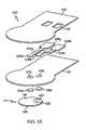
- FIG. 1is an exploded view of an example of a transducer assembly 100 that may be used for structural health monitoring in accordance with a embodiment of the present disclosure.
- the transducer assembly 100includes a first layer 102 of dielectric material.
- the first layer 102 of dielectric materialmay be a polyimide film or similar flexible non-conductive material.
- the first layermay have a thickness of about 0.1905 mm (7.5 mils) or less.
- the polyimide film or first layer 102may be Dupont Pyralux LF9150 or a similar material. Pyralux is a trademark of E.I. Du Pont De Nemours and Company in the United States, other countries or both.
- a pair of electrically conductive traces 104are disposed adjacent to, bonded to or attached by other means to the first dielectric layer 102 or polyimide film, as is the case with Dupont Pyralux LF9150 and various polyimide-copper laminated materials.
- the material of layer 102may also be a non-conductive composite material with bonded copper traces 104, such as a resin impregnated fiberglass fabric.
- Each conductive trace 104may be one of the following copper or similar conductive material, conductive silk-screened ink, and a bundle of conductive, conductively coated semiconductive or conductively coated non-conductive fibers.
- Each conductive trace 104includes a first contact pad 106 and a second contact pad 108.
- the first dielectric layer 102includes a pair of vias 110 or opens formed therein to expose each of the first contact pads 106 to provide a wiring interface to connect the traces 104 to a structural health monitoring unit (not shown in Figure 1A ) or similar device.
- the vias 110may be formed by a laser ablatement process or other process capable of precisely forming such openings 110.
- a second layer 112 of dielectric materialis attached to the first layer 102 of dielectric material with the pair of electrically conductive traces 104 disposed between the first and second layers 102 and 112 of dielectric material.
- An electromechanical transducer 114is attached to the second layer 112 of dielectric material on an opposite side of the second layer 112 relative to the first layer 102 of dielectric material.
- Each second contact pad 108is electrically connected to the electromechanical transducer 114 through the second layer 112 of dielectric material.
- the second layer 112 of dielectric materialmay includes a layer of non-conductive adhesive to encapsulate the electrically conductive traces 104 and to attach the electromechanical transducer 114 to the first layer 102 of dielectric material or polyimide film.
- Each of the two contact pads 108 of each of the conductive traces 104is electrically connected through holes 117 in the second layer 112 of non-conductive dielectric material by an electrically conductive adhesive film 116, adhesive patch or adhesive in a paste form.
- the layer of non-conductive adhesive 112may have a thickness of about 0.1016 mm (4 mils) or less.
- the layer of non-conductive adhesive 112may be Ablefilm CF563 or a similar non-conductive adhesive.
- the electrically conductive adhesive film 116 or patchmay also have a thickness of about 0.1016 mm (4 mils) or less.
- the electrically conductive adhesive film 116may be an epoxy film, such as Ablefilm CR3350 or a similar conductive film. Ablefilm is a trademark of National Starch and Chemical Investment Holding Corporation of New Castle, Delaware in the United States, other countries or both.
- Conductive adhesive electrical bonds 116are attached to transducer 114 by connecting to electrical pads 118 and 120. Note that electrical pads 118 and 120 on the disk or transducer 114 are separated by an electrically isolating non-conductive layer 122. Conductive adhesive bond 116 also connects to pads 108.
- the electromechanical transducer 114may be a flat ceramic piezoelectric ultrasonic transducer disk, sensor or a similar device capable of transmitting stress waves in a structure or object under test as described herein. As used herein, transducer may also mean sensor or any device for performing the functions described herein.
- the electromechanical transducer disk 114may have a thickness of about 0.254 mm (10 mils) or less.
- the electromechanical transducer 114may be a 0.254mm (10 mils) lead, zirconate, titanate piezoelectric ceramic material with electrically conductive, yet separately isolated plates attached or bonded to each side of the piezo disk such as piezo materials from APC International, Ltd.
- the electromechanical transducer 114may include a signal transmitting face 124 opposite to the non-conductive layer 112.
- the piezo materialis able to be excited sending stress waves into the object and/or able to receive return stress waves from the object for monitoring the structural health of the object or to detect any anomalies in the object.
- the stress wavesmay be ultrasonic lamb waves or similar waves to detect any anomalies, defect or damage.
- the second layer 112 of non-conductive materialmay be an adhesive or combination of dielectric material and adhesive with holes and conductive adhesive film patches 116 extending through the holes 117 in the second layer 112 are adapted to assist in attaching or holding the electromechanical transducer 114 to the first layer 102 of dielectric material or polyimide film.
- the attachment of the electromechanical transducer 114is such that the signal transmitting face 124 forms a substantially flat or planar surface with the non-conductive adhesive layer 112 to prevent any voids or substantial steps when the transducer assembly 100 is attached to an object for structural health monitoring or to detect any anomalies.
- Figure 3illustrates an example of a transducer assembly 304, similar to the transducer assembly 100, attached to an object 302 being monitored without any voids or substantial steps between the transducer assembly 304 and the object 302.
- the non-conductive layer 320(112 in Figure 1A ) is formed to be flat with the electromechanical transducer 322 as shown in Figure 3 (114 in Figure 1A ). This flatness provides a tight seal around the edges of the transducer 322 as shown in Figure 3 .
- the transducer assembly 100may be attached to an object for structural health monitoring without any additional structural layers or thick components. Only a thin layer of electrically conductive adhesive or non-conductive adhesive 326 as shown in Figure 3 is used to bond the transducer assembly 322 (as shown in Figure 3 ) which may be the same as transducer assembly 100 in Figure 1A .
- This described electromechanical transducer assembly 100 bonding methodprovides a substantially flat, low profile structure when attached to the object 302 to substantially prevent any inadvertent impacts to the transducer assembly that may result in possible damage to the transducer assembly. Additionally, the simple, minimal layer structure minimizes mechanical impedance mismatch and increases signal-to-noise ratio during structural health monitoring.
- the substantially flat bottom surfaceprovides a surface that contributes to uniform bonding of the transducer assembly to the object or structure to which the transducer will be applied.
- the simplistic structure of the transducer or sensor assembly 100 of the embodiment of the present disclosure illustrated in Figure 1Acan be inexpensively and efficiently fabricated as described in more detail with reference to Figure 2 .
- the low fabrication costsmay permit a multiplicity of such transducer or sensor assemblies to be deployed on an aircraft at selected locations, or on any structure as part of a structural health monitoring program.
- FIG 2is an illustration of an example of a lay-up configuration 200 for forming a transducer assembly 202 in accordance with an embodiment of the present disclosure.
- the transducer assembly 202may be the same as the transducer assembly 100 in Figure 1A .
- the uncured transducer assembly 202may be disposed on or in an autoclave tool 204.
- a first separator sheet 206 of heat resistant, non-stick material and a peel ply or layer 208 of release materialmay be placed or disposed between the transducer assembly 202 and the autoclave tool 204.
- the first separator sheet 206 of heat resistant, non-stick materialmay be a solid sheet of fluorinated ethylene propylene (FEP) or similar heat resistant, non-stick material.
- the release material layer 208may be any type of peel ply material or the like. The first separator sheet 206 and release material layer 208 or peel ply will permit the transducer assembly 202 to be easily removed from the autoclave tool 204 after cu
- a temperature tape 210may be placed on an opposite side of the uncured transducer assembly 202 relative to the autoclave tool 204.
- the temperature tape 210may be any type of adhesive material to maintain the relative positioning of the different plies of the uncured transducer assembly 202 with respect to each other while in an uncured state.
- a second separator sheet 212may be placed on the temperature tape 210.
- the second separator sheet 212may be a perforated FEP separator or a similar layer of material that will permit a full vacuum to be applied to the transducer assembly 202 and permit removal of the transducer assembly 202 after curing.
- a bleeder sheet 214may be placed on the second separator sheet 212.
- the bleeder sheet 214may be a 120# fiberglass bleeder or similar mechanism to permit the full vacuum to be applied to the transducer assembly 202.
- a third separator sheet 216may be placed on the bleeder sheet 214.
- the third separator sheet 216may be a solid FEP separator layer.
- An airweave breather 218may be placed on the third separator sheet 216. Again, the airweave breather 218 and perforated separator sheet 216 permit the vacuum to be applied to the transducer assembly 202 and the perforated separator 216 facilitates removal of the assembly 202 after curing.
- the layered configuration 220may be placed in a vacuum chamber or bag 222 and sealed.
- the vacuum bag 222may be sealed with tape 224, such as tacky tape or similar adhesive or other suitable means.
- a full vacuummay be applied to the configuration 220 through a vacuum port 226.
- the uncured transducer assembly 202may be cured using a predetermined cure schedule to cause the cured transducer assembly 202 to be substantially free of any air pockets and resin rich areas. For example, a full vacuum may be applied to the transducer assembly 202 during curing.
- a curing temperaturemay be applied to the transducer assembly 202 and may be ramped up at about 11 K (20 degrees Fahrenheit (F)) per minute from an ambient temperature to about 422 K (300 degrees F). The curing temperature may be held at about 422 K (300 degrees F) for about 30 minutes. After about 30 minutes, the curing temperature may be ramped down at about 11 K (20 degrees F) per minute to the ambient temperature.
- transducer assemblyconsisting of a flat interface surface, uniform, and rugged structure to substantially prevent damage due to inadvertent impacts to the transducer assembly 202 resulting in possible damage.
- Some other benefits to this design and cure schedulemay include good signal performance with high strength of signal by way of maximizing structural stress transmission into and from the piezoelectric disk and thus transmitting lamb waves efficiently into an object under test or being monitored, such as object 302 in Figure 3 .
- the flat surface between piezo disk 322 and adhesive 320are visible in Figure 3 .
- the compact and efficient design of the transducerhelps minimize mechanical impedance mismatch and minimizes noise to help provide a high signal-to-noise ratio during transducer usage.
- full encapsulation of the piezoelectric disk or sensor and circuitryprovides additional protection against harsh environmental conditions such as moisture, freeze/thaw cycles, and chemical spillage.
- the larger-than-piezo-disk, flat, and uniform bonding surface of the transducerhelps in the bonding process to ensure a uniform void free bond when the transducer is bonded to a structure and helps minimize stress concentrations, protecting against structural static and fatigue failures, acoustic vibration failures, and electromechanical interference (EMI) exposure, and incidental damage due to impact of the transducer.
- EMIelectromechanical interference
- the non-conductive ply 112 in Figure 1Aensures isolation between conductor (signal) and ground to avoid short-circuits.
- the conductive ply or patches 116ensure guaranteed electrical connection between electrical path and piezoelectric transducer disk 114.
- the transducer assembly as shown 100, 202 and 304may have an additional layer of material (not shown) between transducer 304 and bonding adhesive 326. This material layer will help electrically isolate the transducer 304 from the structure 302.
- Transducer bonding adhesive 326may be a non-conductive or conductive adhesive; thus helping to provide a transducer 304 that is grounded or isolated from the structure 302.
- the conductive or non-conductive adhesive 326 after curingwill provide electrical isolation or electrical conductivity between the transducer disk 304 and any object or structure 302 to which the transducer 304 is bonded.
- the isolation between the transducer 304 and the structure 302is due to the fact that the substantially flat bottom design interface extends over material 320 and disk 322 of the transducer assembly 304 allowing for a consistent, uniform bond-line between the transducer disk 322 and any object or structure being monitored 302.
- an optional, thin (approximately 0.1016 mm (4 mils) or less) non-conductive isolation layer 330may be added to the bottom of the transducer assembly as shown in figure 3 .
- the non-conductive isolation layermay be non-conductive resin; and the resin may be reinforced such as with a thin non-conductive fabric made from non-conductive fiber tows.
- the non-conductive fiber reinforcement usedmay be glass or other non-conductive fibers.
- the non-conductive layer 330may also have mirco non-conductive beads or other non-conductive thickness-controlling or spacing material added to the non-conductive resin (layer 330) to help ensure a uniform thickness for layer 330 and electrical isolation.
- Figure 3is a cross-sectional view of the transducer assembly 100 of Figure 1B (304 in Figure 3 ) taken along lines 3-3 included in an exemplary system 300 for structural health monitoring of an object 302, such as a vehicle or the like, in accordance with an embodiment of the present disclosure.
- the object 302may be an aerospace vehicle, terrestrial vehicle, watercraft, civil structure, such as a bridge, deck or railway, or other type vehicle or structure.
- the system 300may include a plurality of transducer or sensor assemblies 304 located at predetermined positions on the object 302.
- a cross-sectional view of a single transducer assembly 304is illustrated in Figure 3 for purposes of explaining the present disclosure.
- the transducer assembly 304may be similar or the same as the transducer assembly 100 of Figures 1A and 1B .
- the transducer assembly 304may include a polyimide film 306.
- a pair of electrically conductive traces 308may be bonded to the polyimide film 306.
- Each conductive trace 308may be similar to conductive traces 104 in Figure 1A .
- each of the conductive traces 308may include a first contact pad 310 and a second contact pad 312.
- the polyimide filmmay have a pair of vias or openings formed therein, similar to vias 110 in Figure 1A , to expose each of the first contact pads 310 for connection to a structural health monitoring unit 314.
- Each of the first contact pads 310may be connected to the structural health monitoring unit 314 by a suitable connection means 316, such as a connector wire electrically bonded using solder to each first contact pad 310, a wire electrically bonded and attached to each contact pad 310 by a conductive adhesive, or other means suitable for the particular application of the transducer assembly 304 and the object 302 being monitored.
- a suitable connection means 316such as a connector wire electrically bonded using solder to each first contact pad 310, a wire electrically bonded and attached to each contact pad 310 by a conductive adhesive, or other means suitable for the particular application of the transducer assembly 304 and the object 302 being monitored.
- An electrical insulating and sealing potting compound 318 or other suitable materialmay be deposited on each first contact pad 310 and connection thereto to seal the transducer assembly 304 from environmental conditions.
- a layer or ply 320 of non-conductive adhesivemay be attached to the polyimide film 306 with the electrically conductive traces 308 encapsulated between the non-conductive layer 320 and the polyimide film 306.
- the non-conductive layer 320may be adapted to attach a flat electromechanical transducer 322 or piezoelectric transducer, sensor or disk to the polyimide film 306 such that a signal transmitting face 324a of the piezoelectric disk or transducer 322 will form a substantially flat or planar surface with the non-conductive adhesive layer 320 to prevent any voids or steps when the transducer assembly 304 is attached to the object 302. This provides good mechanical or acoustic coupling for sound or stress waves between the transducer 322 and the object 302. If the optional isolation layer 330 is present then the interface surface of the transducer to the structure is 324b.
- the transducer assembly 304may also include a pair of electrically conductive films or patches 328 to connect each of the second contact pads 312 to the actuator or sensor disk 322 through the non-conductive adhesive layer 320.
- the conductive films or patches 328may be similar to or the same as conductive films or patches 116 of Figure 1A .
- a transducer assembly installation adhesive 326may be used to attach each transducer assembly 304 to the object 302.
- the transducer assembly 302is attached to the object 302 without any additional layers or components to provide a substantially flat mating surface 324a (or 324b when optional isolation layer 330 is present), low profile structure when attached to the object 302 for health monitoring to substantially minimize any inadvertent impacts to the transducer assembly 304 that could result in possible damage, help ensure electrical isolation with structure 302, and reduce stress concentrations in the transducer by ensuring a uniform bond, and help ensure consistent bonding with no voids.
- the compact, minimal layer or ply designalso overall minimizes mechanical impedance mismatch for better performance reducing electrical noise susceptibility and increasing the signal-to-noise ratio during the actuating and sensing of the transducer 304 for structural health monitoring or data gathering.
- the structural health monitoring unit 314may be an ultrasonic transceiver, data acquisition unit or similar device for transmitting, receiving and analyzing stress waves, lamb waves, ultrasonic signals, or other non-destructive evaluation (NDE) type signals or waves into the object 302 to detect and locate any anomalies, defect or damage. Accordingly, the system 300 functions as a means to transmit and receive ultrasonic signals efficiently through a structure, such as object 302.
- the structural health monitoring unit 314 or data acquisition unitmay pulse a signal burst with a specified frequency content in the form of varying electrical voltage. The voltage may be sent through the wiring connection including conductive traces 308 to the transducer 322 or sensor. The voltage strains the piezoelectric component of the transducer 322 in a compression mode.
- This mechanical straininterrogates the object 302 through stress waves, which are omni-directional modes which locally propagate throughout the object 302.
- Neighboring or adjacent transducers similar to transducer 304receive the mechanical stress waves and by the reverse piezoelectric effect, electrical voltage is generated and monitored through the transducer assembly 304.
- the present disclosureprovides a low-cost, easy-to-fabricate transducer assembly for monitoring structural health of an object, such as an aircraft or other structure.
- the low costpermits a multiplicity of such transducer assemblies to be located at strategic positions on the aircraft for structural health monitoring.
- the transducersare small, do not add appreciable weight and can be easily installed, as described above, as well as removed or replaced quite simply.
- the transducer assemblies as described hereinare highly resistant to environment conditions, such as temperature, moisture, impact damage, chemicals and the like.
- the transducer assembliescan be electrically isolated from the structure being monitored, although non-isolated embodiments are also possible.
Landscapes
- Engineering & Computer Science (AREA)
- Aviation & Aerospace Engineering (AREA)
- Physics & Mathematics (AREA)
- General Physics & Mathematics (AREA)
- Investigating Or Analyzing Materials By The Use Of Ultrasonic Waves (AREA)
- Transducers For Ultrasonic Waves (AREA)
- Testing Or Calibration Of Command Recording Devices (AREA)
- Measuring And Recording Apparatus For Diagnosis (AREA)
Abstract
Description
- The present disclosure relates to monitoring structural health of an object, such as an aircraft or other vehicle, and more particularly to a structural health monitoring (SHM) transducer assembly and system that may utilize the SHM transducer assembly.
- New, lightweight composite materials, traditional metallic materials, and other materials are being used and optimized in designs more extensively in the aerospace industry for commercial aircraft and other aerospace vehicles, as well as in civil infrastructure, ground transportation, and other industries. The new materials and new designs may be subject to extreme stresses or potential damage from an impact or other cause. For example near a fuselage cargo door surround of a commercial aircraft, baggage handlers often inadvertently collide with and cause impact damage to the airplane fuselage. Any such damage needs to be quickly and efficiently identified, located, and the size and extend determined so that any needed repairs can be performed and to reduce airplane maintenance costs and eliminate airplane cancellation and delays. To implement quick non-destructive evaluations that may be performed quickly to ensure minimal maintenance times, numerous transducers are required. To add such a new inspection system to an airplane or other structure with harsh in-service environments and cost competitiveness, the transducers must be low cost, be able to survive in harsh environments, and perform well over time.
- According to an aspect of the invention there is provided a transducer assembly as claimed in claim 1. According to a further aspect of the invention there is provided a method for forming a transducer assembly as claimed in claim 12.
- Other aspects and features of the present disclosure, as defined solely by the claims, will become apparent to those ordinarily skilled in the art upon review of the following non-limited detailed description of the disclosure in conjunction with the accompanying figures.
Figure 1A is an exploded view of an example of a transducer assembly that may be used for structural health monitoring in accordance with an embodiment of the present disclosure.Figure 1B is a plan view of the transducer assembly ofFigure 1A .Figure 2 is an illustration of an example of a lay-up configuration for forming a transducer assembly in accordance with an embodiment of the present disclosure.Figure 3 is a cross-sectional view of the transducer assembly ofFigure 1B taken along lines 3-3 included in an exemplary system for structural health monitoring of an object, such as a vehicle or the like, in accordance with an embodiment of the present disclosure.- The following detailed description of embodiments refers to the accompanying drawings, which illustrate specific embodiments of the disclosure. Other embodiments having different structures and operations do not depart from the scope of the present disclosure.
Figures 1 is an exploded view of an example of atransducer assembly 100 that may be used for structural health monitoring in accordance with a embodiment of the present disclosure. Thetransducer assembly 100 includes afirst layer 102 of dielectric material. Thefirst layer 102 of dielectric material may be a polyimide film or similar flexible non-conductive material. The first layer may have a thickness of about 0.1905 mm (7.5 mils) or less. The polyimide film orfirst layer 102 may be Dupont Pyralux LF9150 or a similar material. Pyralux is a trademark of E.I. Du Pont De Nemours and Company in the United States, other countries or both.- A pair of electrically
conductive traces 104 are disposed adjacent to, bonded to or attached by other means to the firstdielectric layer 102 or polyimide film, as is the case with Dupont Pyralux LF9150 and various polyimide-copper laminated materials. The material oflayer 102 may also be a non-conductive composite material withbonded copper traces 104, such as a resin impregnated fiberglass fabric. Eachconductive trace 104 may be one of the following copper or similar conductive material, conductive silk-screened ink, and a bundle of conductive, conductively coated semiconductive or conductively coated non-conductive fibers. Eachconductive trace 104 includes afirst contact pad 106 and asecond contact pad 108. The firstdielectric layer 102 includes a pair ofvias 110 or opens formed therein to expose each of thefirst contact pads 106 to provide a wiring interface to connect thetraces 104 to a structural health monitoring unit (not shown inFigure 1A ) or similar device. Thevias 110 may be formed by a laser ablatement process or other process capable of precisely formingsuch openings 110. - A
second layer 112 of dielectric material is attached to thefirst layer 102 of dielectric material with the pair of electricallyconductive traces 104 disposed between the first andsecond layers electromechanical transducer 114 is attached to thesecond layer 112 of dielectric material on an opposite side of thesecond layer 112 relative to thefirst layer 102 of dielectric material. Eachsecond contact pad 108 is electrically connected to theelectromechanical transducer 114 through thesecond layer 112 of dielectric material. - The
second layer 112 of dielectric material may includes a layer of non-conductive adhesive to encapsulate the electricallyconductive traces 104 and to attach theelectromechanical transducer 114 to thefirst layer 102 of dielectric material or polyimide film. Each of the twocontact pads 108 of each of theconductive traces 104 is electrically connected through holes 117 in thesecond layer 112 of non-conductive dielectric material by an electrically conductive adhesive film 116, adhesive patch or adhesive in a paste form. - The layer of
non-conductive adhesive 112 may have a thickness of about 0.1016 mm (4 mils) or less. The layer of non-conductiveadhesive 112 may be Ablefilm CF563 or a similar non-conductive adhesive. The electrically conductive adhesive film 116 or patch may also have a thickness of about 0.1016 mm (4 mils) or less. The electrically conductive adhesive film 116 may be an epoxy film, such as Ablefilm CR3350 or a similar conductive film. Ablefilm is a trademark of National Starch and Chemical Investment Holding Corporation of New Castle, Delaware in the United States, other countries or both. Conductive adhesive electrical bonds 116 are attached to transducer 114 by connecting toelectrical pads electrical pads transducer 114 are separated by an electrically isolatingnon-conductive layer 122. Conductive adhesive bond 116 also connects topads 108. - The
electromechanical transducer 114 may be a flat ceramic piezoelectric ultrasonic transducer disk, sensor or a similar device capable of transmitting stress waves in a structure or object under test as described herein. As used herein, transducer may also mean sensor or any device for performing the functions described herein. Theelectromechanical transducer disk 114 may have a thickness of about 0.254 mm (10 mils) or less. Theelectromechanical transducer 114 may be a 0.254mm (10 mils) lead, zirconate, titanate piezoelectric ceramic material with electrically conductive, yet separately isolated plates attached or bonded to each side of the piezo disk such as piezo materials from APC International, Ltd. - The
electromechanical transducer 114 may include asignal transmitting face 124 opposite to thenon-conductive layer 112. When thesignal transmitting surface 124 is bonded to an object, the piezo material is able to be excited sending stress waves into the object and/or able to receive return stress waves from the object for monitoring the structural health of the object or to detect any anomalies in the object. As described in more detail herein with reference toFigure 3 , the stress waves may be ultrasonic lamb waves or similar waves to detect any anomalies, defect or damage. - The
second layer 112 of non-conductive material may be an adhesive or combination of dielectric material and adhesive with holes and conductive adhesive film patches 116 extending through the holes 117 in thesecond layer 112 are adapted to assist in attaching or holding theelectromechanical transducer 114 to thefirst layer 102 of dielectric material or polyimide film. The attachment of theelectromechanical transducer 114 is such that thesignal transmitting face 124 forms a substantially flat or planar surface with the non-conductiveadhesive layer 112 to prevent any voids or substantial steps when thetransducer assembly 100 is attached to an object for structural health monitoring or to detect any anomalies.Figure 3 illustrates an example of atransducer assembly 304, similar to thetransducer assembly 100, attached to anobject 302 being monitored without any voids or substantial steps between thetransducer assembly 304 and theobject 302. The non-conductive layer 320 (112 inFigure 1A ) is formed to be flat with theelectromechanical transducer 322 as shown inFigure 3 (114 inFigure 1A ). This flatness provides a tight seal around the edges of thetransducer 322 as shown inFigure 3 . - The
transducer assembly 100 may be attached to an object for structural health monitoring without any additional structural layers or thick components. Only a thin layer of electrically conductive adhesive ornon-conductive adhesive 326 as shown inFigure 3 is used to bond the transducer assembly 322 (as shown inFigure 3 ) which may be the same astransducer assembly 100 inFigure 1A . This describedelectromechanical transducer assembly 100 bonding method provides a substantially flat, low profile structure when attached to theobject 302 to substantially prevent any inadvertent impacts to the transducer assembly that may result in possible damage to the transducer assembly. Additionally, the simple, minimal layer structure minimizes mechanical impedance mismatch and increases signal-to-noise ratio during structural health monitoring. The substantially flat bottom surface provides a surface that contributes to uniform bonding of the transducer assembly to the object or structure to which the transducer will be applied. - As described above, the simplistic structure of the transducer or
sensor assembly 100 of the embodiment of the present disclosure illustrated inFigure 1A can be inexpensively and efficiently fabricated as described in more detail with reference toFigure 2 . The low fabrication costs may permit a multiplicity of such transducer or sensor assemblies to be deployed on an aircraft at selected locations, or on any structure as part of a structural health monitoring program. Figure 2 is an illustration of an example of a lay-upconfiguration 200 for forming atransducer assembly 202 in accordance with an embodiment of the present disclosure. Thetransducer assembly 202 may be the same as thetransducer assembly 100 inFigure 1A . Theuncured transducer assembly 202 may be disposed on or in anautoclave tool 204. Afirst separator sheet 206 of heat resistant, non-stick material and a peel ply or layer 208 of release material may be placed or disposed between thetransducer assembly 202 and theautoclave tool 204. Thefirst separator sheet 206 of heat resistant, non-stick material may be a solid sheet of fluorinated ethylene propylene (FEP) or similar heat resistant, non-stick material. Therelease material layer 208 may be any type of peel ply material or the like. Thefirst separator sheet 206 andrelease material layer 208 or peel ply will permit thetransducer assembly 202 to be easily removed from theautoclave tool 204 after curing.- A
temperature tape 210 may be placed on an opposite side of theuncured transducer assembly 202 relative to theautoclave tool 204. Thetemperature tape 210 may be any type of adhesive material to maintain the relative positioning of the different plies of theuncured transducer assembly 202 with respect to each other while in an uncured state. Asecond separator sheet 212 may be placed on thetemperature tape 210. Thesecond separator sheet 212 may be a perforated FEP separator or a similar layer of material that will permit a full vacuum to be applied to thetransducer assembly 202 and permit removal of thetransducer assembly 202 after curing. - A
bleeder sheet 214 may be placed on thesecond separator sheet 212. Thebleeder sheet 214 may be a 120# fiberglass bleeder or similar mechanism to permit the full vacuum to be applied to thetransducer assembly 202. Athird separator sheet 216 may be placed on thebleeder sheet 214. Thethird separator sheet 216 may be a solid FEP separator layer. Anairweave breather 218 may be placed on thethird separator sheet 216. Again, theairweave breather 218 andperforated separator sheet 216 permit the vacuum to be applied to thetransducer assembly 202 and theperforated separator 216 facilitates removal of theassembly 202 after curing. - The
layered configuration 220 may be placed in a vacuum chamber orbag 222 and sealed. Thevacuum bag 222 may be sealed withtape 224, such as tacky tape or similar adhesive or other suitable means. A full vacuum may be applied to theconfiguration 220 through avacuum port 226. - The
uncured transducer assembly 202 may be cured using a predetermined cure schedule to cause the curedtransducer assembly 202 to be substantially free of any air pockets and resin rich areas. For example, a full vacuum may be applied to thetransducer assembly 202 during curing. A curing temperature may be applied to thetransducer assembly 202 and may be ramped up at about 11 K (20 degrees Fahrenheit (F)) per minute from an ambient temperature to about 422 K (300 degrees F). The curing temperature may be held at about 422 K (300 degrees F) for about 30 minutes. After about 30 minutes, the curing temperature may be ramped down at about 11 K (20 degrees F) per minute to the ambient temperature. - As a result of the high temperature and pressure cure, many benefits ensue including a transducer assembly consisting of a flat interface surface, uniform, and rugged structure to substantially prevent damage due to inadvertent impacts to the
transducer assembly 202 resulting in possible damage. Some other benefits to this design and cure schedule may include good signal performance with high strength of signal by way of maximizing structural stress transmission into and from the piezoelectric disk and thus transmitting lamb waves efficiently into an object under test or being monitored, such asobject 302 inFigure 3 . The flat surface betweenpiezo disk 322 and adhesive 320 are visible inFigure 3 . The compact and efficient design of the transducer helps minimize mechanical impedance mismatch and minimizes noise to help provide a high signal-to-noise ratio during transducer usage. When bonded to an object, such as 302 inFigure 3 , full encapsulation of the piezoelectric disk or sensor and circuitry (as surrounded by adhesive 320) provides additional protection against harsh environmental conditions such as moisture, freeze/thaw cycles, and chemical spillage. The larger-than-piezo-disk, flat, and uniform bonding surface of the transducer helps in the bonding process to ensure a uniform void free bond when the transducer is bonded to a structure and helps minimize stress concentrations, protecting against structural static and fatigue failures, acoustic vibration failures, and electromechanical interference (EMI) exposure, and incidental damage due to impact of the transducer. Thenon-conductive ply 112 inFigure 1A ensures isolation between conductor (signal) and ground to avoid short-circuits. The conductive ply or patches 116 ensure guaranteed electrical connection between electrical path andpiezoelectric transducer disk 114. The transducer assembly as shown 100, 202 and 304 may have an additional layer of material (not shown) betweentransducer 304 andbonding adhesive 326. This material layer will help electrically isolate thetransducer 304 from thestructure 302.Transducer bonding adhesive 326 may be a non-conductive or conductive adhesive; thus helping to provide atransducer 304 that is grounded or isolated from thestructure 302. As shown inFigure 3 , the conductive or non-conductive adhesive 326 after curing will provide electrical isolation or electrical conductivity between thetransducer disk 304 and any object orstructure 302 to which thetransducer 304 is bonded. For the case of electrical isolation, the isolation between thetransducer 304 and thestructure 302 is due to the fact that the substantially flat bottom design interface extends overmaterial 320 anddisk 322 of thetransducer assembly 304 allowing for a consistent, uniform bond-line between thetransducer disk 322 and any object or structure being monitored 302. - If full electrical isolation between the
transducer assembly 304 and thestructure 302 is desired, an optional, thin (approximately 0.1016 mm (4 mils) or less)non-conductive isolation layer 330 may be added to the bottom of the transducer assembly as shown infigure 3 . The non-conductive isolation layer may be non-conductive resin; and the resin may be reinforced such as with a thin non-conductive fabric made from non-conductive fiber tows. The non-conductive fiber reinforcement used may be glass or other non-conductive fibers. In another embodiment of this disclosure thenon-conductive layer 330 may also have mirco non-conductive beads or other non-conductive thickness-controlling or spacing material added to the non-conductive resin (layer 330) to help ensure a uniform thickness forlayer 330 and electrical isolation.Figure 3 is a cross-sectional view of thetransducer assembly 100 ofFigure 1B (304 inFigure 3 ) taken along lines 3-3 included in anexemplary system 300 for structural health monitoring of anobject 302, such as a vehicle or the like, in accordance with an embodiment of the present disclosure. Theobject 302 may be an aerospace vehicle, terrestrial vehicle, watercraft, civil structure, such as a bridge, deck or railway, or other type vehicle or structure. Thesystem 300 may include a plurality of transducer orsensor assemblies 304 located at predetermined positions on theobject 302. A cross-sectional view of asingle transducer assembly 304 is illustrated inFigure 3 for purposes of explaining the present disclosure. Thetransducer assembly 304 may be similar or the same as thetransducer assembly 100 ofFigures 1A and1B . Accordingly, thetransducer assembly 304 may include apolyimide film 306. A pair of electricallyconductive traces 308 may be bonded to thepolyimide film 306. Eachconductive trace 308 may be similar toconductive traces 104 inFigure 1A . Accordingly, each of theconductive traces 308 may include afirst contact pad 310 and asecond contact pad 312. The polyimide film may have a pair of vias or openings formed therein, similar tovias 110 inFigure 1A , to expose each of thefirst contact pads 310 for connection to a structuralhealth monitoring unit 314. Each of thefirst contact pads 310 may be connected to the structuralhealth monitoring unit 314 by a suitable connection means 316, such as a connector wire electrically bonded using solder to eachfirst contact pad 310, a wire electrically bonded and attached to eachcontact pad 310 by a conductive adhesive, or other means suitable for the particular application of thetransducer assembly 304 and theobject 302 being monitored. An electrical insulating and sealingpotting compound 318 or other suitable material may be deposited on eachfirst contact pad 310 and connection thereto to seal thetransducer assembly 304 from environmental conditions. - A layer or ply 320 of non-conductive adhesive may be attached to the
polyimide film 306 with the electricallyconductive traces 308 encapsulated between thenon-conductive layer 320 and thepolyimide film 306. Similar to that previously described, thenon-conductive layer 320 may be adapted to attach a flatelectromechanical transducer 322 or piezoelectric transducer, sensor or disk to thepolyimide film 306 such that asignal transmitting face 324a of the piezoelectric disk ortransducer 322 will form a substantially flat or planar surface with the non-conductiveadhesive layer 320 to prevent any voids or steps when thetransducer assembly 304 is attached to theobject 302. This provides good mechanical or acoustic coupling for sound or stress waves between thetransducer 322 and theobject 302. If theoptional isolation layer 330 is present then the interface surface of the transducer to the structure is 324b. - The
transducer assembly 304 may also include a pair of electrically conductive films orpatches 328 to connect each of thesecond contact pads 312 to the actuator orsensor disk 322 through the non-conductiveadhesive layer 320. The conductive films orpatches 328 may be similar to or the same as conductive films or patches 116 ofFigure 1A . - A transducer
assembly installation adhesive 326 may be used to attach eachtransducer assembly 304 to theobject 302. In accordance with an embodiment of the present disclosure, thetransducer assembly 302 is attached to theobject 302 without any additional layers or components to provide a substantiallyflat mating surface 324a (or 324b whenoptional isolation layer 330 is present), low profile structure when attached to theobject 302 for health monitoring to substantially minimize any inadvertent impacts to thetransducer assembly 304 that could result in possible damage, help ensure electrical isolation withstructure 302, and reduce stress concentrations in the transducer by ensuring a uniform bond, and help ensure consistent bonding with no voids. The compact, minimal layer or ply design also overall minimizes mechanical impedance mismatch for better performance reducing electrical noise susceptibility and increasing the signal-to-noise ratio during the actuating and sensing of thetransducer 304 for structural health monitoring or data gathering. - The structural
health monitoring unit 314 may be an ultrasonic transceiver, data acquisition unit or similar device for transmitting, receiving and analyzing stress waves, lamb waves, ultrasonic signals, or other non-destructive evaluation (NDE) type signals or waves into theobject 302 to detect and locate any anomalies, defect or damage. Accordingly, thesystem 300 functions as a means to transmit and receive ultrasonic signals efficiently through a structure, such asobject 302. The structuralhealth monitoring unit 314 or data acquisition unit may pulse a signal burst with a specified frequency content in the form of varying electrical voltage. The voltage may be sent through the wiring connection includingconductive traces 308 to thetransducer 322 or sensor. The voltage strains the piezoelectric component of thetransducer 322 in a compression mode. This mechanical strain interrogates theobject 302 through stress waves, which are omni-directional modes which locally propagate throughout theobject 302. Neighboring or adjacent transducers similar totransducer 304 receive the mechanical stress waves and by the reverse piezoelectric effect, electrical voltage is generated and monitored through thetransducer assembly 304. - In summary, the present disclosure provides a low-cost, easy-to-fabricate transducer assembly for monitoring structural health of an object, such as an aircraft or other structure. The low cost permits a multiplicity of such transducer assemblies to be located at strategic positions on the aircraft for structural health monitoring. The transducers are small, do not add appreciable weight and can be easily installed, as described above, as well as removed or replaced quite simply. The transducer assemblies as described herein are highly resistant to environment conditions, such as temperature, moisture, impact damage, chemicals and the like. The transducer assemblies can be electrically isolated from the structure being monitored, although non-isolated embodiments are also possible.
- The terminology used herein is for the purpose of describing particular embodiments only and is not intended to be limiting of the disclosure. As used herein, the singular forms "a", "an" and "the" are intended to include the plural forms as well, unless the context clearly indicates otherwise. It will be further understood that the terms "comprises" and/or "comprising," and "includes" and/or "including" when used in this specification, specify the presence of stated features, integers, steps, operations, elements, and/or components, but do not preclude the presence or addition of one or more other features, integers, steps, operations, elements, components, and/or groups thereof.
Claims (15)
- A transducer assembly (100, 202, 304), comprising:a first layer (102) of dielectric material;a pair of electrically conductive traces (104) adjacent to the first dielectric layer (102), wherein each of the electrically conductive traces (104) include a first contact pad (106, 310) and a second contact pad (108, 312) and wherein the first layer (102) of dielectric material includes a pair of vias (110) formed therein to expose each of the first contact pads (106, 310);a second layer (112) of dielectric material attached to the first layer (102) of dielectric material with the pair of electrically conductive traces (104) disposed between the first and second layers (102 & 112) of dielectric material;a pair of holes (117a, 117b) formed in the second layer (112) of dielectric material;a transducer (114, 322) attached to an opposite side of the second layer (112) of dielectric material from the first layer (102) of dielectric material; andan electrically conductive adhesive film (116a, 116b) patch or paste disposed within each of the pair of holes (117a, 117b) to electrically connect each second contact pad (108, 312) to the transducer (114, 322), wherein the transducer (114, 322) is attached to the second layer (112) of dielectric material such that a signal transmitting face of the transducer forms a substantially planar surface with the second layer of dielectric material to prevent any voids or steps when the transducer assembly (100, 202, 304) is attached to an object.
- The transducer assembly (100, 202, 304) of claim 1, further comprising another layer of non-conductive material (330) attached to a surface of the transducer (114, 322) opposite to the second layer (112) of dielectric material to isolate a structure (302) being monitored from the transducer (114, 322).
- The transducer assembly (100, 202, 304) of claim 2, wherein the other layer of non-conductive material (330) comprises a fiber reinforced resin including a thickness of about 0.1016 mm (4 mils) or less.
- The transducer assembly (100, 202, 304) of claim 1, wherein the first layer (102) of dielectric material comprises a polyimide film having a thickness of about 0.1905 mm (7.5 mils) or less. of about 0.1905 mm (7.5 mils) or less.
- The transducer assembly (100, 202, 304) of claim 1, wherein the second layer (112) of dielectric material comprises a layer of non-conductive adhesive to encapsulate the electrically conductive traces (104) and to attach the transducer (114, 322) to the first layer (102) of dielectric material and wherein each of the second contact pads (108, 312) is electrically connected through the layer of non-conductive adhesive to the transducer (114, 322) by an electrically conductive adhesive film (116).
- The transducer assembly (100, 202, 304) of claim 5, wherein the transducer (114, 322) comprises a signal transmitting face (324), and wherein the layer of non-conductive adhesive is adapted to attach the transducer (114, 322) to the first layer (102) of dielectric material such that the signal transmitting face (324) of the transducer (114, 322) forms a substantially flat surface with the non-conductive adhesive layer (320) to prevent any voids and to create a uniform bond line when the transducer assembly (114, 322) is attached to an object (302) for structural health monitoring.
- The transducer assembly (100, 202, 304) of claim 6, wherein the first layer (102) of dielectric material, the pair of electrically conductive traces (104), the layer of non-conductive adhesive (330), the electrically conductive film adhesive (116) and the transducer (114, 322) are disposed relative to one another and cured at a predetermined temperature and one of a predetermined vacuum pressure, or a predetermined vacuum pressure and a predetermined autoclave pressure to form a resulting transducer assembly that is substantially free of any air pockets and resin rich areas.
- The transducer assembly (100, 202, 304) of claim 5, whereinthe layer of non-conductive adhesive (320) includes a thickness of about 0.1016 mm (4 mils) or less.
- The transducer assembly (100, 202, 304) of claim 1, wherein the transducer (114, 322) comprises a flat electromechanical transducer.
- The transducer assembly (100, 202, 304) of claim 9, wherein the transducer (114, 322) comprisesa ceramic piezoelectric ultrasonic transducer disk with a thickness of about 0.254mm (10 mils) or less.
- The transducer assembly (100, 202, 304) of claim 1, wherein the transducer assembly (100, 202, 304) is attachable to an object (302) for structural health monitoring of the object by an installation adhesive and the first contact pads (106, 310) of the conductive traces (104) are connectable to a structural health monitoring unit (314) without the transducer assembly (100, 202, 304) including any additional layers of material and substantially without any voids between the transducer assembly (100, 202, 304) and the object (302).
- A method for forming a transducer assembly (100, 202, 304), comprising:providing a first layer (102) of dielectric material;placing a pair of electrically conductive traces (104) adjacent to the first dielectric layer (102), wherein each of the electrically conductive traces (104) includes a first contact pad (106, 310) and a second contact pad (108, 312);forming a pair of vias (110) in the first layer (102) of dielectric material to expose each of the first contact pads (106, 310);attaching a second layer (112) of dielectric material to the first layer (102) of dielectric material with the pair of electrically conductive traces (104) disposed between the first and second layers (102 & 112) of dielectric material;forming a pair of holes (117a, 117b) in the second layer (112) of dielectric material;attaching a transducer (114, 322) to an opposite side of the second layer (112) of dielectric material from the first layer of dielectric material; anddisposing an electrically conductive adhesive film (116a, 116b), patch or paste within each of the pair of holes (117a, 117b) of electrically connect each second contact pad (108, 312) to the transducer (114, 322), wherein the transducer (114, 322) is attached to the second layer (112) of dielectric material such that a signal transmitting face of the transducer forms a substantially planar surface with the second layer of dielectric material to prevent any voids or steps when the transducer assembly (100, 202, 304) is attached to an object.
- The method of claim 12, further comprising curing the transducer assembly (100, 202, 304) using a predetermined cure schedule to cause a cured transducer assembly (100, 202, 304) to be substantially free of any air pockets and resin rich areas.
- The method of claim 13, wherein curing the transducer assembly (100, 202, 304) comprises:placing an uncured transducer assembly (100, 202, 304) on an autoclave tool (204) separated from the autoclave tool (204) by at least one layer of a heat resistant, non-stick or release material 208);placing a temperature tape (210) on an opposite side of the uncured transducer assembly (100, 202, 304) relative to the autoclave tool (204);placing a first separator sheet (206) of heat resistant, non-stick or release material on the temperature tape (210);placing a bleeder (214) on the first separator sheet (206) to permit applying a full vacuum to the transducer assembly (100, 202, 304);placing a second separator sheet (212) of heat resistant, non-stick or release material on the bleeder (214);placing an airweave breather (218) on the second separator sheet (212); andattaching a vacuum bag (222) to apply a full vacuum to the transducer assembly (100, 202, 304).
- The method of claim 13, further comprising:applying a full vacuum to an uncured transducer assembly (100, 202, 304);ramping up a curing temperature applied to the uncured transducer assembly (100, 202, 304) at about 11 K (20 degrees Fahrenheit,) per minute from ambient temperature to about 422 K (300 degrees Fahrenheit,)holding the curing temperature at about 422 K (300 degrees Fahrenheit,) for about 30 minutes; andramping down the curing temperature at about 11 K (20 degrees Fahrenheit,) per minute to about ambient temperature.
Applications Claiming Priority (2)
| Application Number | Priority Date | Filing Date | Title |
|---|---|---|---|
| US11/754,167US7743659B2 (en) | 2007-05-25 | 2007-05-25 | Structural health monitoring (SHM) transducer assembly and system |
| PCT/US2008/064545WO2008147891A1 (en) | 2007-05-25 | 2008-05-22 | Structural health monitoring (shm) transducer assembly and system |
Publications (2)
| Publication Number | Publication Date |
|---|---|
| EP2162930A1 EP2162930A1 (en) | 2010-03-17 |
| EP2162930B1true EP2162930B1 (en) | 2012-07-25 |
Family
ID=39832277
Family Applications (1)
| Application Number | Title | Priority Date | Filing Date |
|---|---|---|---|
| EP08769622ANot-in-forceEP2162930B1 (en) | 2007-05-25 | 2008-05-22 | Structural health monitoring (shm) transducer assembly and system |
Country Status (5)
| Country | Link |
|---|---|
| US (1) | US7743659B2 (en) |
| EP (1) | EP2162930B1 (en) |
| JP (1) | JP5323820B2 (en) |
| CN (1) | CN101785124B (en) |
| WO (1) | WO2008147891A1 (en) |
Families Citing this family (36)
| Publication number | Priority date | Publication date | Assignee | Title |
|---|---|---|---|---|
| US7696676B2 (en)* | 2006-12-18 | 2010-04-13 | Lockheed Martin Corporation | Piezoelectric composite apparatus and related methods |
| US8347722B2 (en)* | 2008-01-22 | 2013-01-08 | Acellent Technologies, Inc. | Method and apparatus for conducting structural health monitoring in a cryogenic, high vibration environment |
| US8794980B2 (en) | 2011-12-14 | 2014-08-05 | Keyssa, Inc. | Connectors providing HAPTIC feedback |
| US8554136B2 (en) | 2008-12-23 | 2013-10-08 | Waveconnex, Inc. | Tightly-coupled near-field communication-link connector-replacement chips |
| US8886388B2 (en)* | 2009-06-29 | 2014-11-11 | The Boeing Company | Embedded damage detection system for composite materials of an aircraft |
| US8745864B2 (en) | 2009-08-10 | 2014-06-10 | The Boeing Company | Method of coupling digitizing sensors to a structure |
| US8237548B2 (en) | 2010-06-01 | 2012-08-07 | The Boeing Company | Structural health management device and associated system and method |
| US8680745B2 (en)* | 2010-07-21 | 2014-03-25 | General Electric Company | Device for measuring material thickness |
| EP2601501B1 (en)* | 2010-08-05 | 2017-03-29 | The Boeing Company | Systems and methods of coupling digitizing sensors to a structure |
| US9618481B2 (en) | 2010-11-05 | 2017-04-11 | National Research Council Of Canada | Ultrasonic transducer assembly and system for monitoring structural integrity |
| US8707787B1 (en)* | 2011-03-04 | 2014-04-29 | The Boeing Company | Time delay based health monitoring system using a sensor network |
| KR101615082B1 (en) | 2011-03-24 | 2016-04-29 | 키사, 아이엔씨. | Integrated circuit with electromagnetic communication |
| US8544328B2 (en) | 2011-04-11 | 2013-10-01 | The Boeing Company | Transducer based health monitoring system |
| US8811526B2 (en) | 2011-05-31 | 2014-08-19 | Keyssa, Inc. | Delta modulated low power EHF communication link |
| TWI569031B (en) | 2011-06-15 | 2017-02-01 | 奇沙公司 | Near-end sensing and distance measurement using EHF signals |
| US9417213B1 (en)* | 2011-07-11 | 2016-08-16 | The Boeing Company | Non-destructive evaluation system for aircraft |
| TWI562555B (en) | 2011-10-21 | 2016-12-11 | Keyssa Inc | Contactless signal splicing |
| CN107276641B (en) | 2012-03-02 | 2021-07-02 | 凯萨股份有限公司 | Duplex communication system and method |
| ITTO20120504A1 (en)* | 2012-06-11 | 2013-12-12 | Alenia Aermacchi Spa | METHOD OF CONSTRUCTION OF AN AERONAUTICAL STRUCTURE WITH CLOSED PROFILE PROVIDED WITH DEFORMATION SENSORS |
| EP2883271B1 (en) | 2012-08-10 | 2020-07-22 | Keyssa, Inc. | Dielectric coupling systems for ehf communications |
| US9374154B2 (en) | 2012-09-14 | 2016-06-21 | Keyssa, Inc. | Wireless connections with virtual hysteresis |
| WO2014100058A1 (en) | 2012-12-17 | 2014-06-26 | Waveconnex, Inc. | Modular electronics |
| TWI551093B (en) | 2013-03-15 | 2016-09-21 | 奇沙公司 | Extremely high frequency communication chip |
| KR20150132459A (en)* | 2013-03-15 | 2015-11-25 | 키사, 아이엔씨. | Ehf secure communication device |
| JP6690193B2 (en)* | 2014-11-12 | 2020-04-28 | Tdk株式会社 | Piezoelectric layer, piezoelectric element, piezoelectric actuator, piezoelectric sensor, hard disk drive, and inkjet printer device |
| CN104819859B (en)* | 2015-04-16 | 2017-04-19 | 南京航空航天大学 | Surface mount solidification method for coupling large-area complex-configuration piezoelectric intelligent interlayer and structure |
| US20160370210A1 (en)* | 2015-06-18 | 2016-12-22 | Amphenol Thermometrics, Inc. | Modular flexible sensor array |
| WO2017003552A1 (en)* | 2015-06-30 | 2017-01-05 | GM Global Technology Operations LLC | Method of determining volatile organic compounds |
| US10091567B2 (en)* | 2015-11-13 | 2018-10-02 | The Boeing Company | Embedded lighting, microphone, and speaker features for composite panels |
| EP3257655B1 (en)* | 2016-06-13 | 2019-10-16 | Airbus Defence and Space GmbH | Sensor intigration during the joining of strucutral parts |
| US10811590B1 (en) | 2016-06-23 | 2020-10-20 | Plastipak Packaging, Inc. | Containers with sensing and/or communication features |
| US10012553B2 (en)* | 2016-08-12 | 2018-07-03 | The Hong Kong Polytechnic University | Coated nanofiller/polymer composite sensor network for guided-wave-based structural health monitoring |
| JP6961067B2 (en)* | 2017-07-07 | 2021-11-05 | シーメンス アクティエンゲゼルシャフト | Electric short circuit device |
| CN110567745B (en)* | 2019-09-16 | 2022-06-07 | 中国铁道科学研究院集团有限公司铁道建筑研究所 | A detection and evaluation system for bridge underwater piers |
| TWI712739B (en)* | 2019-11-04 | 2020-12-11 | 科際精密股份有限公司 | Actuation system |
| DE102021129229B9 (en) | 2021-11-10 | 2022-11-03 | Tdk Electronics Ag | Piezoelectric transducer |
Family Cites Families (10)
| Publication number | Priority date | Publication date | Assignee | Title |
|---|---|---|---|---|
| US5184516A (en)* | 1991-07-31 | 1993-02-09 | Hughes Aircraft Company | Conformal circuit for structural health monitoring and assessment |
| US6370964B1 (en)* | 1998-11-23 | 2002-04-16 | The Board Of Trustees Of The Leland Stanford Junior University | Diagnostic layer and methods for detecting structural integrity of composite and metallic materials |
| JP3980847B2 (en)* | 2001-07-31 | 2007-09-26 | 太陽誘電株式会社 | Piezoelectric speaker and electronic device using the same |
| WO2003035281A2 (en) | 2001-10-23 | 2003-05-01 | Schindel David W | Ultrasonic printed circuit board transducer |
| JP3790813B2 (en)* | 2001-10-24 | 2006-06-28 | 独立行政法人産業技術総合研究所 | Damage sensing sheet |
| JP2007521490A (en)* | 2003-09-22 | 2007-08-02 | ヒョン−ユン,キム | Structural health monitor sensor and system |
| EP1735586B1 (en) | 2004-03-03 | 2018-02-14 | Metis Design Corporation | Damage detection device |
| US7458266B2 (en)* | 2004-09-27 | 2008-12-02 | Samsung Electronics Co. Ltd. | Method and apparatus for detecting a load change upon a structure and analyzing characteristics of resulting damage |
| US7103507B2 (en) | 2004-09-28 | 2006-09-05 | Dimitry Gorinevsky | Structure health monitoring system and method |
| ES2555683T3 (en) | 2004-10-07 | 2016-01-07 | Metis Design Corporation | Sensor infrastructure with integrated electronics |
- 2007
- 2007-05-25USUS11/754,167patent/US7743659B2/ennot_activeExpired - Fee Related
- 2008
- 2008-05-22EPEP08769622Apatent/EP2162930B1/ennot_activeNot-in-force
- 2008-05-22JPJP2010510428Apatent/JP5323820B2/ennot_activeExpired - Fee Related
- 2008-05-22CNCN2008800157551Apatent/CN101785124B/ennot_activeExpired - Fee Related
- 2008-05-22WOPCT/US2008/064545patent/WO2008147891A1/enactiveApplication Filing
Also Published As
| Publication number | Publication date |
|---|---|
| EP2162930A1 (en) | 2010-03-17 |
| CN101785124B (en) | 2012-08-08 |
| US7743659B2 (en) | 2010-06-29 |
| JP2010528566A (en) | 2010-08-19 |
| US20080289426A1 (en) | 2008-11-27 |
| CN101785124A (en) | 2010-07-21 |
| WO2008147891A1 (en) | 2008-12-04 |
| JP5323820B2 (en) | 2013-10-23 |
Similar Documents
| Publication | Publication Date | Title |
|---|---|---|
| EP2162930B1 (en) | Structural health monitoring (shm) transducer assembly and system | |
| CA2769272C (en) | Integrated phased array transducer, system and methodology for structural health monitoring of aerospace structures | |
| CN103502802B (en) | Systems and methods for monitoring bond integrity | |
| US7246521B2 (en) | Diagnostic system for monitoring structural health conditions | |
| US9267906B2 (en) | Bondline embedded current sensor | |
| JP6690910B2 (en) | COMPOSITE MATERIAL STRUCTURE HAVING JOINT OF COMPOSITE MATERIAL AND METAL, AND MANUFACTURING METHOD THEREOF | |
| US10210740B2 (en) | System and method for monitoring structural health of bonded components | |
| Balasubramaniam | Lamb-wave-based structural health monitoring technique for inaccessible regions in complex composite structures. | |
| US9964521B2 (en) | Detecting damage in a composite panel without removing overlying insulation | |
| US12411112B2 (en) | Transducer, device and method for monitoring integrity of an adhesive bond | |
| US11639916B2 (en) | Composite part with integral electronic instrumentation circuit and its manufacturing method | |
| WO2014181935A1 (en) | Smart paint and smart paint device using piezoelectric material | |
| US10830736B2 (en) | Sensor skin | |
| CN209927781U (en) | 8 x 8 matrix ultrasonic probe with triangular array elements arranged for nondestructive testing of bolts | |
| US20110260581A1 (en) | Flexible Phased Array Sensor | |
| Nitschke et al. | Tailored embeddable sensor-actuator layers for CFRP aerospace structures | |
| Hildebrandt et al. | Influence of accelerated aging on the acoustic properties of a ceramic microsystem for structural health monitoring | |
| GB2617844A (en) | Fluid measurement apparatus | |
| KR100772292B1 (en) | Sensors and systems for health monitoring of structures | |
| KR100784089B1 (en) | Sensors and systems for health monitoring of structures |
Legal Events
| Date | Code | Title | Description |
|---|---|---|---|
| PUAI | Public reference made under article 153(3) epc to a published international application that has entered the european phase | Free format text:ORIGINAL CODE: 0009012 | |
| 17P | Request for examination filed | Effective date:20091217 | |
| AK | Designated contracting states | Kind code of ref document:A1 Designated state(s):AT BE BG CH CY CZ DE DK EE ES FI FR GB GR HR HU IE IS IT LI LT LU LV MC MT NL NO PL PT RO SE SI SK TR | |
| AX | Request for extension of the european patent | Extension state:AL BA MK RS | |
| DAX | Request for extension of the european patent (deleted) | ||
| 17Q | First examination report despatched | Effective date:20110214 | |
| RIC1 | Information provided on ipc code assigned before grant | Ipc:H01L 41/113 20060101ALI20111026BHEP Ipc:G01M 5/00 20060101ALI20111026BHEP Ipc:H01L 41/053 20060101AFI20111026BHEP | |
| GRAP | Despatch of communication of intention to grant a patent | Free format text:ORIGINAL CODE: EPIDOSNIGR1 | |
| GRAS | Grant fee paid | Free format text:ORIGINAL CODE: EPIDOSNIGR3 | |
| GRAA | (expected) grant | Free format text:ORIGINAL CODE: 0009210 | |
| AK | Designated contracting states | Kind code of ref document:B1 Designated state(s):AT BE BG CH CY CZ DE DK EE ES FI FR GB GR HR HU IE IS IT LI LT LU LV MC MT NL NO PL PT RO SE SI SK TR | |
| REG | Reference to a national code | Ref country code:GB Ref legal event code:FG4D | |
| REG | Reference to a national code | Ref country code:CH Ref legal event code:EP | |
| REG | Reference to a national code | Ref country code:AT Ref legal event code:REF Ref document number:568018 Country of ref document:AT Kind code of ref document:T Effective date:20120815 Ref country code:IE Ref legal event code:FG4D | |
| REG | Reference to a national code | Ref country code:DE Ref legal event code:R096 Ref document number:602008017433 Country of ref document:DE Effective date:20120920 | |
| REG | Reference to a national code | Ref country code:NL Ref legal event code:VDEP Effective date:20120725 | |
| REG | Reference to a national code | Ref country code:AT Ref legal event code:MK05 Ref document number:568018 Country of ref document:AT Kind code of ref document:T Effective date:20120725 | |
| REG | Reference to a national code | Ref country code:LT Ref legal event code:MG4D Effective date:20120725 | |
| PG25 | Lapsed in a contracting state [announced via postgrant information from national office to epo] | Ref country code:HR Free format text:LAPSE BECAUSE OF FAILURE TO SUBMIT A TRANSLATION OF THE DESCRIPTION OR TO PAY THE FEE WITHIN THE PRESCRIBED TIME-LIMIT Effective date:20120725 Ref country code:AT Free format text:LAPSE BECAUSE OF FAILURE TO SUBMIT A TRANSLATION OF THE DESCRIPTION OR TO PAY THE FEE WITHIN THE PRESCRIBED TIME-LIMIT Effective date:20120725 Ref country code:LT Free format text:LAPSE BECAUSE OF FAILURE TO SUBMIT A TRANSLATION OF THE DESCRIPTION OR TO PAY THE FEE WITHIN THE PRESCRIBED TIME-LIMIT Effective date:20120725 Ref country code:FI Free format text:LAPSE BECAUSE OF FAILURE TO SUBMIT A TRANSLATION OF THE DESCRIPTION OR TO PAY THE FEE WITHIN THE PRESCRIBED TIME-LIMIT Effective date:20120725 Ref country code:NO Free format text:LAPSE BECAUSE OF FAILURE TO SUBMIT A TRANSLATION OF THE DESCRIPTION OR TO PAY THE FEE WITHIN THE PRESCRIBED TIME-LIMIT Effective date:20121025 Ref country code:BE Free format text:LAPSE BECAUSE OF FAILURE TO SUBMIT A TRANSLATION OF THE DESCRIPTION OR TO PAY THE FEE WITHIN THE PRESCRIBED TIME-LIMIT Effective date:20120725 Ref country code:IS Free format text:LAPSE BECAUSE OF FAILURE TO SUBMIT A TRANSLATION OF THE DESCRIPTION OR TO PAY THE FEE WITHIN THE PRESCRIBED TIME-LIMIT Effective date:20121125 Ref country code:CY Free format text:LAPSE BECAUSE OF FAILURE TO SUBMIT A TRANSLATION OF THE DESCRIPTION OR TO PAY THE FEE WITHIN THE PRESCRIBED TIME-LIMIT Effective date:20120725 | |
| PG25 | Lapsed in a contracting state [announced via postgrant information from national office to epo] | Ref country code:LV Free format text:LAPSE BECAUSE OF FAILURE TO SUBMIT A TRANSLATION OF THE DESCRIPTION OR TO PAY THE FEE WITHIN THE PRESCRIBED TIME-LIMIT Effective date:20120725 Ref country code:GR Free format text:LAPSE BECAUSE OF FAILURE TO SUBMIT A TRANSLATION OF THE DESCRIPTION OR TO PAY THE FEE WITHIN THE PRESCRIBED TIME-LIMIT Effective date:20121026 Ref country code:PL Free format text:LAPSE BECAUSE OF FAILURE TO SUBMIT A TRANSLATION OF THE DESCRIPTION OR TO PAY THE FEE WITHIN THE PRESCRIBED TIME-LIMIT Effective date:20120725 Ref country code:SI Free format text:LAPSE BECAUSE OF FAILURE TO SUBMIT A TRANSLATION OF THE DESCRIPTION OR TO PAY THE FEE WITHIN THE PRESCRIBED TIME-LIMIT Effective date:20120725 Ref country code:PT Free format text:LAPSE BECAUSE OF FAILURE TO SUBMIT A TRANSLATION OF THE DESCRIPTION OR TO PAY THE FEE WITHIN THE PRESCRIBED TIME-LIMIT Effective date:20121126 Ref country code:SE Free format text:LAPSE BECAUSE OF FAILURE TO SUBMIT A TRANSLATION OF THE DESCRIPTION OR TO PAY THE FEE WITHIN THE PRESCRIBED TIME-LIMIT Effective date:20120725 | |
| PG25 | Lapsed in a contracting state [announced via postgrant information from national office to epo] | Ref country code:NL Free format text:LAPSE BECAUSE OF FAILURE TO SUBMIT A TRANSLATION OF THE DESCRIPTION OR TO PAY THE FEE WITHIN THE PRESCRIBED TIME-LIMIT Effective date:20120725 | |
| PG25 | Lapsed in a contracting state [announced via postgrant information from national office to epo] | Ref country code:DK Free format text:LAPSE BECAUSE OF FAILURE TO SUBMIT A TRANSLATION OF THE DESCRIPTION OR TO PAY THE FEE WITHIN THE PRESCRIBED TIME-LIMIT Effective date:20120725 Ref country code:RO Free format text:LAPSE BECAUSE OF FAILURE TO SUBMIT A TRANSLATION OF THE DESCRIPTION OR TO PAY THE FEE WITHIN THE PRESCRIBED TIME-LIMIT Effective date:20120725 Ref country code:EE Free format text:LAPSE BECAUSE OF FAILURE TO SUBMIT A TRANSLATION OF THE DESCRIPTION OR TO PAY THE FEE WITHIN THE PRESCRIBED TIME-LIMIT Effective date:20120725 Ref country code:ES Free format text:LAPSE BECAUSE OF FAILURE TO SUBMIT A TRANSLATION OF THE DESCRIPTION OR TO PAY THE FEE WITHIN THE PRESCRIBED TIME-LIMIT Effective date:20121105 Ref country code:CZ Free format text:LAPSE BECAUSE OF FAILURE TO SUBMIT A TRANSLATION OF THE DESCRIPTION OR TO PAY THE FEE WITHIN THE PRESCRIBED TIME-LIMIT Effective date:20120725 | |
| PG25 | Lapsed in a contracting state [announced via postgrant information from national office to epo] | Ref country code:SK Free format text:LAPSE BECAUSE OF FAILURE TO SUBMIT A TRANSLATION OF THE DESCRIPTION OR TO PAY THE FEE WITHIN THE PRESCRIBED TIME-LIMIT Effective date:20120725 Ref country code:IT Free format text:LAPSE BECAUSE OF FAILURE TO SUBMIT A TRANSLATION OF THE DESCRIPTION OR TO PAY THE FEE WITHIN THE PRESCRIBED TIME-LIMIT Effective date:20120725 | |
| PLBE | No opposition filed within time limit | Free format text:ORIGINAL CODE: 0009261 | |
| STAA | Information on the status of an ep patent application or granted ep patent | Free format text:STATUS: NO OPPOSITION FILED WITHIN TIME LIMIT | |
| 26N | No opposition filed | Effective date:20130426 | |
| PG25 | Lapsed in a contracting state [announced via postgrant information from national office to epo] | Ref country code:BG Free format text:LAPSE BECAUSE OF FAILURE TO SUBMIT A TRANSLATION OF THE DESCRIPTION OR TO PAY THE FEE WITHIN THE PRESCRIBED TIME-LIMIT Effective date:20121025 | |
| REG | Reference to a national code | Ref country code:DE Ref legal event code:R097 Ref document number:602008017433 Country of ref document:DE Effective date:20130426 | |
| PG25 | Lapsed in a contracting state [announced via postgrant information from national office to epo] | Ref country code:MC Free format text:LAPSE BECAUSE OF FAILURE TO SUBMIT A TRANSLATION OF THE DESCRIPTION OR TO PAY THE FEE WITHIN THE PRESCRIBED TIME-LIMIT Effective date:20120725 | |
| REG | Reference to a national code | Ref country code:CH Ref legal event code:PL | |
| PG25 | Lapsed in a contracting state [announced via postgrant information from national office to epo] | Ref country code:LI Free format text:LAPSE BECAUSE OF NON-PAYMENT OF DUE FEES Effective date:20130531 Ref country code:CH Free format text:LAPSE BECAUSE OF NON-PAYMENT OF DUE FEES Effective date:20130531 | |
| REG | Reference to a national code | Ref country code:IE Ref legal event code:MM4A | |
| PG25 | Lapsed in a contracting state [announced via postgrant information from national office to epo] | Ref country code:IE Free format text:LAPSE BECAUSE OF NON-PAYMENT OF DUE FEES Effective date:20130522 | |
| PG25 | Lapsed in a contracting state [announced via postgrant information from national office to epo] | Ref country code:MT Free format text:LAPSE BECAUSE OF FAILURE TO SUBMIT A TRANSLATION OF THE DESCRIPTION OR TO PAY THE FEE WITHIN THE PRESCRIBED TIME-LIMIT Effective date:20120725 | |
| PG25 | Lapsed in a contracting state [announced via postgrant information from national office to epo] | Ref country code:TR Free format text:LAPSE BECAUSE OF FAILURE TO SUBMIT A TRANSLATION OF THE DESCRIPTION OR TO PAY THE FEE WITHIN THE PRESCRIBED TIME-LIMIT Effective date:20120725 | |
| PG25 | Lapsed in a contracting state [announced via postgrant information from national office to epo] | Ref country code:HU Free format text:LAPSE BECAUSE OF FAILURE TO SUBMIT A TRANSLATION OF THE DESCRIPTION OR TO PAY THE FEE WITHIN THE PRESCRIBED TIME-LIMIT; INVALID AB INITIO Effective date:20080522 Ref country code:LU Free format text:LAPSE BECAUSE OF NON-PAYMENT OF DUE FEES Effective date:20130522 | |
| REG | Reference to a national code | Ref country code:FR Ref legal event code:PLFP Year of fee payment:9 | |
| REG | Reference to a national code | Ref country code:FR Ref legal event code:PLFP Year of fee payment:10 | |
| REG | Reference to a national code | Ref country code:FR Ref legal event code:PLFP Year of fee payment:11 | |
| REG | Reference to a national code | Ref country code:DE Ref legal event code:R082 Ref document number:602008017433 Country of ref document:DE Representative=s name:SCHIWECK WEINZIERL KOCH PATENTANWAELTE PARTNER, DE | |
| PGFP | Annual fee paid to national office [announced via postgrant information from national office to epo] | Ref country code:DE Payment date:20210527 Year of fee payment:14 Ref country code:FR Payment date:20210525 Year of fee payment:14 | |
| PGFP | Annual fee paid to national office [announced via postgrant information from national office to epo] | Ref country code:GB Payment date:20210527 Year of fee payment:14 | |
| REG | Reference to a national code | Ref country code:DE Ref legal event code:R079 Ref document number:602008017433 Country of ref document:DE Free format text:PREVIOUS MAIN CLASS: H01L0041053000 Ipc:H10N0030880000 | |
| REG | Reference to a national code | Ref country code:DE Ref legal event code:R119 Ref document number:602008017433 Country of ref document:DE | |
| GBPC | Gb: european patent ceased through non-payment of renewal fee | Effective date:20220522 | |
| PG25 | Lapsed in a contracting state [announced via postgrant information from national office to epo] | Ref country code:FR Free format text:LAPSE BECAUSE OF NON-PAYMENT OF DUE FEES Effective date:20220531 | |
| PG25 | Lapsed in a contracting state [announced via postgrant information from national office to epo] | Ref country code:GB Free format text:LAPSE BECAUSE OF NON-PAYMENT OF DUE FEES Effective date:20220522 Ref country code:DE Free format text:LAPSE BECAUSE OF NON-PAYMENT OF DUE FEES Effective date:20221201 |