EP2162711B1 - Temperature sensor assembly and method of manufacturing thereof - Google Patents
Temperature sensor assembly and method of manufacturing thereofDownload PDFInfo
- Publication number
- EP2162711B1 EP2162711B1EP08770363.3AEP08770363AEP2162711B1EP 2162711 B1EP2162711 B1EP 2162711B1EP 08770363 AEP08770363 AEP 08770363AEP 2162711 B1EP2162711 B1EP 2162711B1
- Authority
- EP
- European Patent Office
- Prior art keywords
- temperature
- assembly
- probe
- wire
- conductor
- Prior art date
- Legal status (The legal status is an assumption and is not a legal conclusion. Google has not performed a legal analysis and makes no representation as to the accuracy of the status listed.)
- Revoked
Links
Images


Classifications
- G—PHYSICS
- G01—MEASURING; TESTING
- G01K—MEASURING TEMPERATURE; MEASURING QUANTITY OF HEAT; THERMALLY-SENSITIVE ELEMENTS NOT OTHERWISE PROVIDED FOR
- G01K1/00—Details of thermometers not specially adapted for particular types of thermometer
- G01K1/08—Protective devices, e.g. casings
- G—PHYSICS
- G01—MEASURING; TESTING
- G01K—MEASURING TEMPERATURE; MEASURING QUANTITY OF HEAT; THERMALLY-SENSITIVE ELEMENTS NOT OTHERWISE PROVIDED FOR
- G01K7/00—Measuring temperature based on the use of electric or magnetic elements directly sensitive to heat ; Power supply therefor, e.g. using thermoelectric elements
- G01K7/02—Measuring temperature based on the use of electric or magnetic elements directly sensitive to heat ; Power supply therefor, e.g. using thermoelectric elements using thermoelectric elements, e.g. thermocouples
- G01K7/023—Measuring temperature based on the use of electric or magnetic elements directly sensitive to heat ; Power supply therefor, e.g. using thermoelectric elements using thermoelectric elements, e.g. thermocouples provided with specially adapted connectors
Definitions
- the present disclosurerelates to sensors and, more specifically, to temperature sensor assemblies having one or more temperature sensors and the method of manufacturing such temperature sensor assemblies.
- Sensorsare used in a wide variety of operational environments to monitor operating and environmental characteristics. These sensors can include temperature, pressure, velocity, position, motion, current, voltage, and impedance sensors, by way of example. They are placed in or associated with the operational environment being monitored and are designed for generating an electrical signal or having an electrical characteristic such as an impedance, voltage or current that varies in response to the changes in values as the monitored operating or environment characteristic changes.
- Temperature sensing probesinclude numerous components, such as, for example, a temperature sensing element, various wiring, resistors, diodes, and switches, among others. Generally, the temperature sensing probe is subjected to harsh environments that easily can damage the components of the temperature sensing probe.
- temperature sensing probeis disclosed in DE 10109828 A1 . Furthermore, the temperature sensing probe is subject to mechanical stress due to vibration from surrounding machinery. To reduce the potential for damage to the probe from environmental and mechanical stress, various packaging schemes have been implemented to protect the measuring circuitry of the probe. However, such packaging schemes and the methods that are used for manufacturing often result in premature failure or a reduction in performance of the temperature sensing probe.
- the present disclosuregenerally includes temperature sensor assemblies and methods of manufacturing temperature sensor assemblies that are capable of improved performance in harsh temperature sensing environments and that are cost effective to manufacture.
- a temperature sensor assemblymay include a temperature probe, a mounting connector, a wire set, a transition component, a housing and a circuit
- the temperature probeincludes a probe body, a temperature sensor and at least one conductor configured for providing a temperature signal indicative of a temperature over the at least one conductor
- the mounting connectoris adapted for securing the probe body to a mounting assembly
- the wire sethaving at least one wire corresponding to each of the at least one conductors, each wire having a first end and a second end
- the transition componentadapted for coupling each of the at least one conductors to a first end of the at least one wire of the wire set
- the housinghaving an input for receiving a second end of the wires of the wire set and an output for coupling to a temperature measurement system and providing a temperature characteristic
- a temperature sensor assemblymay include a first temperature sensor probe, a second temperature sensor probe, and an adaptor circuit assembly, the first sensor probe having a first temperature sensor and one or more first conductors coupled to the first temperature sensor and configured for providing a first temperature signal indicative of a first temperature; the second sensor probe having a second temperature sensor and one or more second conductors coupled to the second temperature sensor and configured for providing a second temperature signal indicative of a second temperature, and the adaptor circuit assembly fixedly coupled directly to one or more of the conductors of the first temperature sensor probe and one or more of the conductors of the second temperature sensor probe and having a first input for receiving the first temperature signal and a second input for receiving the second temperature signal, and an output for coupling to a temperature measurement system and providing a first temperature characteristic and a second temperature characteristic, and a circuit configured for receiving the first temperature signal and generating the first temperature characteristic in response to the first temperature signal and receiving the second temperature signal and generating the second temperature characteristic in response to the second temperature signal.
- a method for manufacturing a thermocouple sensor assemblymay include attaching a first wire to a first end of a first conductor, attaching a second wire to a first end of a second conductor, placing a grommet having a first channel over the attachment of the first wire to the first conductor and having a second channel over the attachment of the second wire to the second conductor, placing a transition body over the first and second conductors and about the grommet for securing the grommet and attachments within a cavity of the transition body, joining a first end of the first conductor to a first end of the second conductor to form a thermocouple junction at a second end of the conductors, attaching the transition body to a second end of the probe body, positioning a mounting connector about the outer surface of the probe body between the first end and the second end of the probe body, attaching a collar to an intermediate outer surface of the probe body between the first end of the probe body and the mounting connector, attaching a second end of the first wire to a circuit board, and
- a method for manufacturing a thermocouple sensor assemblymay include stripping a first end of a mineral insulated cable to expose a first conductor and a second conductor, forming a thermocouple junction at a second end of the mineral insulated cable, attaching a collar about an intermediate portion of the probe body, enclosing the second end of the probe body, positioning a mounting connector about an outer surface of the probe body between the first end of the probe body and the collar, placing a transition body over the first end of the probe body, attaching a first wire to the exposed first conductor and the second wire to the exposed second conductor, placing a grommet having a first channel over the attachment of the first wire to the first conductor and having a second channel over the attachment of the second wire to the second conductor, attaching the transition body in a position proximate to the first end of the probe body with the transition body substantially covering the grommet, attaching a second end of the first wire to a circuit board, and attaching a second end of the second wire to the circuit board
- the temperature sensor assembly 10generally includes a temperature probe 12, which includes a tip cap 14 (preferably a metal alloy) at one end of a probe body 16 (preferably mineral insulated (MI) cable).
- a mounting connector 18is secured to the probe body 16, and a collar 20 is positioned between the tip cap 14 and the mounting connector 18.
- a transition component 22covers a second end 24 of the probe body 16 and comprises a transition body 27 encapsulating a grommet 23 (not shown in FIG. 1 ; see FIG. 5 ).
- the grommethas two channels that enclose connectors that terminate conductors of the temperature probe 12 to lead wires 26. The specific details of the grommet, its channels, the connectors, and the conductors are illustrated and described in greater detail below.
- a housing 28receives the lead wires 26 and includes an output portion 30 for coupling to a temperature measurement system and providing a temperature characteristic.
- a circuit assembly(not shown) is enclosed within the housing 28 and is configured for receiving the temperature signal from the temperature probe 12 and generating a temperature characteristic in response to the received temperature signal.
- the temperature probe 12can include a mineral insulated (MI) cable 16 having one or more conductors contained therein or can be a conductor surrounded by a conductor such as a compressed powder.
- the MI cablecan include one or two resistance heating elements or conductors embedded in highly compressed magnesium oxide covered by a copper or an Alloy 825 stainless steel sheath, by way of example.
- the specification of the MI cable 16is based, at least in part, on the application requirements and associated conductivity, resistance and sheath material.
- the mounting connector 18is adapted for securing the temperature probe 12 to a mounting assembly in an operating environment.
- Such an arrangementcan be as simple as a hanger or can include a nut, flange, rotatable connector, or other device.
- the mounting connector 18includes a sealing ring or collar 20 for placing the temperature sensor within a temperature sensing environment that is then sealed by the mounting connector 18.
- the mounting connector 18can be a powder metal high strength nut (in the form of a hex nut or other geometry).
- the power metal nutcan provide for cost effectively securing the temperature probe 12 in a hostile or enclosed environment, such as within an engine, power plant, fluid flow, or chemical process, by way of example.
- the lead wires 26include one or more wires that correspond to one or more of the conductors within the temperature probe 12. Each lead wire 26 includes a first end 32 and a second end 34 and can be stranded or solid wires, among others.
- the transition component 22is adapted for coupling or aiding in the coupling each of the conductors to an end of lead wire 26, as described in greater detail below.
- the housing 28also includes an input portion 36 for receiving an end of the lead wires 26.
- the output portion 30 of the housing 28couples to a temperature measurement system and provides one or more temperature characteristics.
- a circuit assembly(not shown) is enclosed within the housing 28 and is configured for receiving the temperature signal from one or more temperature probes 12 (and/or temperature sensors) and generating temperature characteristics in response to the received temperature signals.
- the temperature sensoris a thermocouple.
- the sensoris a thermocouple that can be formed by coupling the conductors (ungrounded thermocouple) or coupling to the probe body (grounded thermocouple).
- the temperature signaltypically can include a voltage level generated by the thermocouple.
- a cold junction compensation circuitcan be implemented within the probe assembly or within the circuit or housing 28.
- the generated temperature characteristicis a characteristic desired and practical for providing information as a function of the temperature signal and as required or desired by the application, namely a resistance value.
- the circuit assemblyreceives the one or more temperature signals from one or more sensors and/or temperature probes 12 and can generate an output signal or characteristic in response to the signals.
- These output characteristicscan include a ratiometric analog voltage signal (RAVS), a pulse width modulated signal, a variable frequency signal, a variable output impedance, a variable voltage signal, and a variable current signal, by way of example.
- the circuit assemblycan be configured for generating a digital signal including the temperature characteristic, wherein the circuit and the housing are each adapted for coupling to a connected component, network, instrument or controller, such as an engine control module.
- a connected componentsuch as an engine control module.
- theycan be adapted for communication over any well known digital or analog communication facility including a wired or wireless connection.
- thiscan include communication protocols such as a controller area network (CAN).
- CANis just one example of a well known and widely used communication protocol that can be implemented by the circuit and the housing. Additionally, proprietary interfaces and communications protocols can also be implemented.
- the temperature sensor assembly 50includes a first sensor probe 52, a second sensor probe 53, and an adaptor circuit assembly 62.
- Each sensor probe 52, 53can include a probe body, such as a cable 80, containing a temperature sensor (not shown) and one or more conductors coupled to the temperature sensor.
- Each sensor probe 52, 53is configured for providing one or more temperature signals indicative of a temperature about an exterior portion of the sensor probe 52, 53.
- the adaptor circuit assembly 62includes inputs for receiving the temperature signals and an output 53 for coupling to a temperature measurement system and providing one or more temperature characteristics responsive to the received temperature signals.
- a circuitis enclosed within the housing 56 and is configured with electronic circuit components and software such as computer executable instructions for receiving the temperature signals and generating the temperature characteristics in response to one or more temperature signals.
- the lead covers 58can be removed in some embodiments as this cover is optional.
- the lead covers 58can cover all or only a portion of the leads between the temperature probes 12 and housing 56.
- the lead covers 58are shown extending from the housing 56, past the transition components 86, and to an area near the collars 84.
- an adaptor circuit assembly 62is assembled from dual lead wires 54 that lead to connectors 70, which pass through the housing base 72 and into a cavity 73 formed in the housing base 72.
- the connectors 70are in electrical contact with the circuit board 66 and its circuit components 68 in order to provide the temperature signals as previously set forth.
- the cavity 73is enclosed by a cover 74, which may be a potting compound in another form of the present disclosure or used with a potting compound in yet another form, thus protecting and/or sealing the cavity and the electronics therein.
- the sensor probes 52, 53are preferably constructed with cables 80 or constructed sensor tubes having intermediate bends of about 90 degrees from the tip cap 60 to the transition component 86.
- the components of the sensor probes 52, 53include the cable 80, preferably MI and having about a 90 degree bend, a mounting connector 82, a collar 84, and a transition component 86, the transition component 86 comprising a transition body 87 and a grommet 88.
- the lead wires 54are coupled through the transition component 86 for connection to the housing (not shown), which is described in greater detail below.
- the sensor probes 52, 53 as shown in FIGS. 4A to 4Ccan be assembled from a selection of components as shown in one exemplary embodiment of an unassembled "kit” in FIG. 5 .
- the "kit” of FIG. 5includes conductors 90, connectors 92, lead wires 54 having leads 55, an insulator 96, a tube 94, a transition component 22/86 comprising a transition body 27/87 and a grommet 23/88, a mounting connector 18, a collar 20/84, a tip cap 14/60, and a tip disc 93.
- the assembly of these componentswhich may comprise a "kit" will be described below.
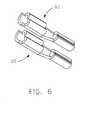
- FIG. 6illustrates one embodiment of connectors 92 that provide for the crimping termination of the temperature probe conductors 90 and the crimping of the sensor leads 55 to a second opposing end of each connector 92.
- the connectors 92may have a straight configuration to provide for an in-line crimp between the leads 55 and the conductors 90.
- the connectors 92when assembled, each reside within their own channel within the grommet 88 enclosed within the transition component 86.
- the connector 92is composed of a metal that can be welded, so that a conductor 90 and/or a wire 54 can be welded to the connector 92 following compressive engagement with the connector 92 such as through crimping.
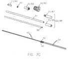
- FIGS. 7A to 7L and to the flow chart of FIG. 8various exemplary embodiments of temperature sensor assembly parts of a kit such as the kit of FIG. 5 , and methods of manufacturing and assembling temperature sensor assemblies are illustrated.
- FIG. 7Aillustrates the unassembled relationship of the formed sensor conductors 90 to the connectors 92, and the connectors 92 to the lead wires 26/54.
- FIG. 7Billustrates the relationship of the sensor conductors 90 after being crimped to the connectors 92 showing how the forming step maintains a physical separation between each of the connectors 92.
- FIG. 7Cillustrates the assembly of the sensor conductors 90, the connectors 92, and the lead wires 26/54 after the lead wires 26/54 are crimped to a second end of each connector 92.
- the other components for the temperature sensor assembly 10, 50are also illustrated in their unassembled state as another embodiment of sensor kit components.
- These componentsinclude an insulator 96, a tube 94, a transition component 22/86 comprising a transition body 27/87 and a grommet 23/88, a mounting connector 18, a collar 20/84, a tip cap 14/60, and a tip disc 93.
- a descriptionis given as to how each of these components may be added to the assembly.
- FIG. 7Dillustrates the assembly after attaching the conductors 90 to the wires 54, via the connectors 92, and placing the attached portions within individual channels of the grommet 23/88, further maintaining a physical separation of the connectors 92 from each other.
- the conductors 90can be welded or otherwise directly attached to the wires 26/54 and those attachments can be enclosed within the channels of the grommet 23/88.
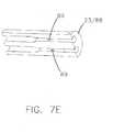
- FIG. 7Eprovides cross-sectional details of the grommet 23/88 illustrating the individual channels 89 within the grommet 23/88 for maintaining the physical separation of the connectors 92.
- the channels 89can have a step nature having two portions each coupled in series and each having a different diameter or channel width.
- FIG. 7Ffurther illustrates an embodiment of a temperature sensor having two sensor conductors 92 attached to connectors (not shown) and wires 26/54 attached to the connectors 92, with the attachments placed within the stepped channels 89 of the grommet 23/88.
- the conductors 90 of FIG. 7Fare each formed so as to extend in an outward direction from a longitudinal axis, which may help facilitate crimping of the conductors 90 to the connectors 92.
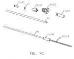
- FIG. 7Gillustrates the assembly of an insulator 96 over sensor conductors 90.
- the probemay comprise a tube 94 or sheath that can be assembled on the insulator 96 in an embodiment where a curved MI cable 80 is not used for the probe body.
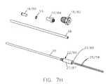
- FIG. 7Hillustrates the transition body 27/87 being assembled over the grommet 23/88 and an end of the insulator 96.
- FIG. 7Iillustrates the assembly of FIGS. 7G and 7H having the tube 94 positioned over the insulator 96.
- the transition body 27/87may be attached to the metal body of the tube 94, such as by welding.
- FIG. 7Jillustrates the mounting connector 18/82 being rotatably positioned about the body of the probe, which is the tube 94 in this example
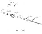
- Fig. 7Kshows the collar 20/84 being positioned between the sensing end 21 of the probe and the mounting connector 18/82.
- the collar 20/84is attached to the probe body (tube 94), such as by welding or other means.
- the collar 20/84is preferably attached to the surface of the probe body or tube 94 to form an airtight seal in some embodiments.
- the mounting connector 18/82 and collar 20/84are each adapted for mounting the temperature probe 12/52 to a mounting surface, such as by screwing the mounting connector 18/82 into a threaded hole and sealing the collar 20/84 and mounting connector 18/82 against the mounting surface, by way of example.
- FIG. 7Lshows the placement of a tip cap 14/60 and/or a tip disc 93 that can be attached, such as through welding, to the end of the metal probe tube 94 or MI cable to enclose the temperature sensor.
- the end of the MI tube 94 or the probe bodycan be left open and not sealed.
- the process 3000includes a step 3002 of attaching a first wire to a first end of a first conductor and attaching a second wire to a first end of a second conductor, another step 3004 of placing a grommet having a first channel over the attachment of the first wire to the first conductor and having a second channel over the attachment of the second wire to the second conductor, another step 3006 of placing a transition body over the first and second conductors and about the grommet for securing the grommet and attachments within a cavity of the transition body, another step 3008 of inserting each conductor into a channel of an insulator, another step 3010 of joining the first end of the first conductor to the first end of the second conductor to form a thermocouple junction at a first end of the insulator, another step 3014 of attaching the transition body to a second end of a probe body, another step 3016 of positioning a mounting connector about the
- the process 3000can also include a step 3020 of attaching a second end of the first wire to an input of a housing and attaching a second end of the second wire to an input of the housing.
- This step 3020may also include attaching a second end of the first wire to a circuit board; and attaching a second end of the second wire to the circuit board.
- the process 3000can include a step 3022 of attaching a cover over the wires, or a portion of the wires.
- the covercould extend from the transition body or probe to an input of the housing, enclosing a portion of the first and second wires within the cover between the transition body and the housing.
- the process 3000can include a step 3024 of bending an intermediate portion of the probe body between the transition body and the mounting connector to form an angle, such as a 90 degree angle.
- the process 3000can also include a step 3026 of connecting the first wire and the second wire to a circuit enclosed within a housing assembly having an input for receiving a second end of the wires, the circuit being configured for receiving a temperature signal from the temperature sensor, for example a thermocouple, and generating the temperature characteristic in response to the received temperature signal. Further, the process 3000 may include a step 3028 of connecting an output of the circuit to an output pin of the housing assembly configured for providing the generated temperature characteristic to a temperature measurement system coupled to the output pin.
- FIG. 9various embodiments of temperature sensor assembly parts (or a kit as shown in FIG. 9 ) and the methods of manufacturing and assembling temperature sensor assemblies (as shown in FIGS. 10A to 10N ) are illustrated, which will now be described.
- the "kit” of FIG. 9includes conductors 290, connectors 292, a MI cable 294, a transition body 227, a grommet 223, a mounting connector 218, a collar 220, and a tip cap 214.
- the assembly of these componentswhich may comprise a "kit", will be described below.
- FIG. 11another example of a process 3100 of assembling a temperature sensor assembly is illustrated.
- the process 3100starts with a MI cable 294 as shown in FIG. 10A , which has an end stripped to expose a first conductor 290 and a second conductor 290 as shown in FIG. 10B .
- the process 3100includes a step 3102 of stripping a first end of a MI cable 294 to expose first and second conductors 290.
- the process 3100also includes a step 3104 of forming a thermocouple junction or other temperature sensor or sensing element at a second end 209 of the mineral insulated cable 294.
- a collar 220is attached about an intermediate portion 208 of the probe body (MI cable 294 in this example).
- the process 3100also includes a step 3106 of attaching the collar 220 about the probe body (MI cable 294).
- An end of the probe bodycan also be closed as discussed above and shown by way of example as an attached tip cap 214 or disc (as shown in FIG. 10D ) or by other means as described above.
- the process 3100may include a step 3108 of enclosing the second end 209 of the probe body.
- the process 3100also includes a step 3110 of positioning a mounting connector 218 about an outer surface of the probe body (MI cable 294) between the first end 211 of the probe body and the collar 220 as shown in FIG. 10D , and a step 3112 of placing a transition body 227 over the first end 211 of the probe body.
- the conductors 290can be formed for crimping or attaching as shown in FIGS. 10E-10F , wherein the conductors 290 are bent so as to be oriented in an outward direction from the longitudinal axis of the MI cable 294.
- the process 3100further includes a step 3114 of attaching the conductors 290 to exposed wire leads 255 of wires 254.
- the conductors 290could be connected directly to the leads 255 of the wires 254, or they may be attached by crimping, welding, soldering, other mechanical coupling, or any other suitable coupling as is known to those skilled in the art.
- This step 3114can include forming an end of each conductor 290 for crimping, and as described above, this can include stripping the end of the conductor 290 to expose a conducting portion, bending or shaping the conducting portion to a desired position or shape, and otherwise preparing the conducting portion for compression and/or welding, soldering, or coupling as is known to those skilled in the art.
- connectors 292can be welded, soldered or otherwise coupled to the end of one of the conductors 290.
- the conductors 290are mechanically crimped to the connectors 292.
- the lead ends 255 of the lead wires 254are also mechanically crimped to the connectors 292. While crimping the mechanical coupling may be sufficient in some embodiments, in other embodiments the crimped coupling between the conductor 290, the wire 254, and the connector 292 can also be welded or soldered.
- FIGS. 10G-10Hthe conductors 290 are mechanically crimped to the connectors 292.
- the lead ends 255 of the lead wires 254are also mechanically crimped to the connectors 292. While crimping the mechanical coupling may be sufficient in some embodiments, in other embodiments the crimped coupling between the conductor 290, the wire 254, and the connector 292 can also be welded or soldered. For example, with reference to FIGS.
- welding or soldering materialmay be added to the connector 292 at a portion 295, or to any other suitable portion of the connector 292.
- the welding described hereincan include any type or method of welding known or developed in the art.
- the combination of mechanical coupling via a crimped connector 292 and a welding of the connector 292 to the conductor 290 and/or to the wire 254can provide benefits.
- the combinationcan provide for improved conductivity, a stronger bond, and decrease failures of this attachment and coupling.
- the process 3100also includes a step 3116 of placing a grommet 223 having one or more channels (not shown) over the attachments of the wires 254 to the conductors 290, as shown in FIG. 10M .
- the process 3100further includes a step 3118 of sliding the transition body 227 over the grommet 223 and attaching the transition body 227, for example by welding, to an end of the probe body with the transition body 227 substantially covering the grommet 223 as shown in FIG. 10N .
- the process 3100can also include a step 3120 of attaching a second end of the first wire to a circuit board and step 3122 of attaching a second end of the second wire to the circuit board.
- the method of manufacturingcan also include connecting the first wire 54 and the second wire 54 to a circuit enclosed within a housing 28 of an adaptor circuit assembly 62 having an input for receiving a second end of the wires 54.
- the circuitcan be configured with electronic components 68 and circuits, memory, a processor, and computer executable instructions configured for receiving one or more temperature signals from temperature sensors, such as a thermocouple, thermistor, or RTD, and generating one or more temperature characteristics in response to the received temperature signals.
- the methodcan also include connecting an output 53 of the circuit to an output connector or pin of the adaptor circuit assembly 62 configured for providing the generated temperature characteristic to a temperature measurement system coupled to the output connector.
- each of the processes described hereincan be repeated to produce one or more probes.
- one or more, for example, two probescan be connected to a common circuit for receiving a plurality of temperature signals.
- the sensor adaptor circuitcan be configured for generating and providing one or more temperature characteristics at the output. Each temperature characteristic can be based on one or more of the temperature signals depending on the desired application and operational environment for the temperature sensor assembly.
- Various benefitsare provided by one or more embodiments of the temperature sensor assemblies and methods of manufacturing such temperature sensor assemblies as generally described in this disclosure.
- One or more of these embodimentscan provide for a high compaction construction, an assembly that is high vibration and shock resistance and therefore provides a longer useful life.
- the temperature sensor assemblies described hereinare capable of use in a wide variety of temperature applications including temperature of flames and temperatures of greater than 900 degree Celsius and have been shown to perform well up to temperatures of 1200 degree Celsius through the use of Alloy 600 in the construction.
- the design and method of constructionprovides for utilizing either a moderate duty lead wire or up to an extra heavy duty lead wire which is the source of many faults and failures for temperature sensor assemblies.
- the assemblies of the present disclosurecan be utilized in a wide variety of temperature sensing applications including low temperature applications such as coolant, brake fluid, inlet air, sea water, and oil temperature.
- more than one temperature probe 12can be included in the temperature sensor assembly 10 or more than one temperature sensor can be included in one or more temperature probes 12.
- one or more of the temperature probes 12 or sensorscan provide separate temperature signals to the circuit associated with one or more measured or sensed temperatures.
- the assemblyincludes a second wire set corresponding to a set of second conductors 90, and a second transition component 22 for coupling each of the second conductors 90 to at least one of the wires 26 of the second wire set.
- the housing 28will include a second input 36 for receiving the second wire set 26.
- the circuitis adapted to receive the second temperature signals and generate a second temperature characteristic indicative of the temperature about the exterior of the second temperature probe 12.
- the temperature probe 12is assembled from a mineral insulated cable having conductors, a metal body, and insulating material. In other embodiments, the temperature probe 12 can be manufactured to include the conductors 90 and the body 16.
- a collar 20is positioned about an exterior surface of the probe body 16 and adapted for engaging the fitting to secure the temperature probe 12 to the mounting assembly 18. The collar 20 is attached, such as by welding, to the exterior surface of the probe body 16. The collar 20 can be attached to the exterior surface of the probe body 16 by any known or future method including laser welding, spin welding, electronic beam welding, resistance welding, and ultrasonic welding, by way of example.
- the transition component 22includes a grommet 23 and a transition body 27.
- the grommet 23can include one or more internal cavities 89 each dimensioned for receiving an end of one of the conductors 90 and for receiving an end 34 of at least one of the at least one wire 26 of the wire set, and the transition body 27 having a cavity substantially enclosing the grommet 23 and being welded to the probe body 16.
- Each of the internal cavities 89 of the grommet 23can also be configured to include a first portion and a second portion coupled and positioned in series with the first portion. The second portion can have a cavity width greater than or less than a cavity width of the first portion.
- the conductors 90/290are directly connected to the wires 26/54/254 by welding or soldering or other known forms of directly connecting conductors 90/290.
- an electrical connector 92/292is utilized to couple the conductors 90/290 to the wires 26/54/254.
- one electrical connector 92/292can include a first end compressively engaging a conductor 90/290 and/or a second end compressively engaging a wire 26/54/254. This can be a crimp compression engagement or similar coupling.
- the electrical connector 92/292can be positioned within one of the internal cavities 89 of the grommet 23/223, when provided.
- the compressive engagementcan be supplemented with a welding or soldering.
- the electrical connector 92/292is preferably composed of a weldable material, such as an alloy 42 material, by way of example.
- the transition component 22/86/222may couple the conductors 90/290 to the wires 26/54/2554 by maintaining a mechanical communication between the wire leads 55/255 and the conductors 90/290.
- the probe body 16is formed from a metal tube 94/294. This can aid in the manufacturing process and help reduce costs.
- one end 209 of the metal tube 94/294can be closed about the temperature sensor by crimping, welding, roll forming and/or swaging an end 209 of the metal tube 94/294.
- a tip cap 14/60/214 or disc 93can be positioned proximate the end 209 of the metal tube 94/294 including the temperature sensor, and can be welded, brazed, or otherwise bonded to the end 209 of the metal tube 94/294 to close the end 209 of the metal tube 94/294 and to seal it for temperature sensing applications.
- the probe body 16/80can be formed, bent or otherwise arranged for mounting on the desired temperature sensing application,
- the probe body 16/80can be bent or formed to have any required angle, and as shown in the examples of some of the figures, has an intermediate portion having an angled portion positioning the first end of the probe body 80 at about 90 degrees from the second end of the probe body 80.
- a cover 58 covering all or a portion of the wire set 54 from the transition portion 22 or probe body 16 to the housing input 36can be provided to provide an aesthetic or practical benefit to the temperature sensor assembly.
- the temperature sensor assembly 10, 50may be placed in a high heat environment where it may be desirable for the cover 58 to be adapted with heat shielding or deflecting material.
- Each of the sensor probes 12/52/53/212can include a wire set having one or more wires 26/54/254 and a transition component 22/86/222 coupled to an end of the probe body 16/80/94/294.
- a grommet 23/88/223 having one or more channels 89 adapted for receiving one or more of the conductors 90/290 and one or more of the wires 26/54/254provides, at least in part, a transition between the probe assembly and the wire set.
- the grommet 23/88/223can also be configured to enclose the coupling of each wire 26/54/254 to each conductor 90/290.
- each sensor probe 12/52/212can include a collar 20/84/220 attached to the exterior of the probe body 16/80/94/294 and a connector 18/82/218 rotatably coupled to the probe body 16/80/94/294 that is configured to engage the collar 20/84/220 and to secure the temperature probe 12/52/212 to a first mounting assembly within the operating environment.
- the leads from the sensor probes 12/52/212are directly connected to the adaptor circuit assembly 62 such that the assembly is an integrated unit, e.g., the probes 12/52/212 are not unpluggable.
- the first leadis fixedly coupled to the circuit and the second lead is fixedly coupled to the circuit.
- Such fixedly couplingpreferably includes a coupling mechanism that does not enable the unplugging or otherwise detachment of the wire 26/54/254 from the adaptor circuit assembly 62 or adaptor circuit housing 28.
- the adaptor circuit assembly 62includes a housing 28 that can be assembled from two or more portions, can be integrated portions, or can be an integrated or unitary body. In some cases, the wire leads 26/54/254 can be retained by the housing 28 itself such as an integral portion of the molded assembly.
Landscapes
- Physics & Mathematics (AREA)
- General Physics & Mathematics (AREA)
- Measuring Temperature Or Quantity Of Heat (AREA)
Description
- The present disclosure relates to sensors and, more specifically, to temperature sensor assemblies having one or more temperature sensors and the method of manufacturing such temperature sensor assemblies.
- The statements in this section merely provide background information related to the present disclosure and may not constitute prior art.
- Sensors are used in a wide variety of operational environments to monitor operating and environmental characteristics. These sensors can include temperature, pressure, velocity, position, motion, current, voltage, and impedance sensors, by way of example. They are placed in or associated with the operational environment being monitored and are designed for generating an electrical signal or having an electrical characteristic such as an impedance, voltage or current that varies in response to the changes in values as the monitored operating or environment characteristic changes.
- Temperature sensing probes include numerous components, such as, for example, a temperature sensing element, various wiring, resistors, diodes, and switches, among others. Generally, the temperature sensing probe is subjected to harsh environments that easily can damage the components of the temperature sensing probe.
- An example of temperature sensing probe is disclosed in
DE 10109828 A1 . Furthermore, the temperature sensing probe is subject to mechanical stress due to vibration from surrounding machinery. To reduce the potential for damage to the probe from environmental and mechanical stress, various packaging schemes have been implemented to protect the measuring circuitry of the probe. However, such packaging schemes and the methods that are used for manufacturing often result in premature failure or a reduction in performance of the temperature sensing probe. - The present disclosure generally includes temperature sensor assemblies and methods of manufacturing temperature sensor assemblies that are capable of improved performance in harsh temperature sensing environments and that are cost effective to manufacture.
- The problem of the invention is based on is solved with an assembly according to claim 1.
- A temperature sensor assembly may include a temperature probe, a mounting connector, a wire set, a transition component, a housing and a circuit, the temperature probe includes a probe body, a temperature sensor and at least one conductor configured for providing a temperature signal indicative of a temperature over the at least one conductor, the mounting connector is adapted for securing the probe body to a mounting assembly, the wire set having at least one wire corresponding to each of the at least one conductors, each wire having a first end and a second end, the transition component adapted for coupling each of the at least one conductors to a first end of the at least one wire of the wire set, the housing having an input for receiving a second end of the wires of the wire set and an output for coupling to a temperature measurement system and providing a temperature characteristic, and the circuit enclosed within the housing and configured for receiving the temperature signal from the temperature probe and generating the temperature characteristic in response to the received temperature signal.
- A temperature sensor assembly may include a first temperature sensor probe, a second temperature sensor probe, and an adaptor circuit assembly, the first sensor probe having a first temperature sensor and one or more first conductors coupled to the first temperature sensor and configured for providing a first temperature signal indicative of a first temperature; the second sensor probe having a second temperature sensor and one or more second conductors coupled to the second temperature sensor and configured for providing a second temperature signal indicative of a second temperature, and the adaptor circuit assembly fixedly coupled directly to one or more of the conductors of the first temperature sensor probe and one or more of the conductors of the second temperature sensor probe and having a first input for receiving the first temperature signal and a second input for receiving the second temperature signal, and an output for coupling to a temperature measurement system and providing a first temperature characteristic and a second temperature characteristic, and a circuit configured for receiving the first temperature signal and generating the first temperature characteristic in response to the first temperature signal and receiving the second temperature signal and generating the second temperature characteristic in response to the second temperature signal.
- A method for manufacturing a thermocouple sensor assembly may include attaching a first wire to a first end of a first conductor, attaching a second wire to a first end of a second conductor, placing a grommet having a first channel over the attachment of the first wire to the first conductor and having a second channel over the attachment of the second wire to the second conductor, placing a transition body over the first and second conductors and about the grommet for securing the grommet and attachments within a cavity of the transition body, joining a first end of the first conductor to a first end of the second conductor to form a thermocouple junction at a second end of the conductors, attaching the transition body to a second end of the probe body, positioning a mounting connector about the outer surface of the probe body between the first end and the second end of the probe body, attaching a collar to an intermediate outer surface of the probe body between the first end of the probe body and the mounting connector, attaching a second end of the first wire to a circuit board, and attaching a second end of the second wire to the circuit board.
- A method for manufacturing a thermocouple sensor assembly may include stripping a first end of a mineral insulated cable to expose a first conductor and a second conductor, forming a thermocouple junction at a second end of the mineral insulated cable, attaching a collar about an intermediate portion of the probe body, enclosing the second end of the probe body, positioning a mounting connector about an outer surface of the probe body between the first end of the probe body and the collar, placing a transition body over the first end of the probe body, attaching a first wire to the exposed first conductor and the second wire to the exposed second conductor, placing a grommet having a first channel over the attachment of the first wire to the first conductor and having a second channel over the attachment of the second wire to the second conductor, attaching the transition body in a position proximate to the first end of the probe body with the transition body substantially covering the grommet, attaching a second end of the first wire to a circuit board, and attaching a second end of the second wire to the circuit board.
- The drawings described herein are for illustration purposes only and are not intended to limit the scope of the present disclosure in any way.
FIG. 1 is a perspective view of a temperature sensor assembly having a single temperature probe and constructed in accordance with the principles of the present disclosure;FIG. 2A is a perspective view of a temperature sensor assembly having dual temperature probes and lead covers constructed in accordance with the principles of the present disclosure;FIG. 2B is a partially exploded perspective view of the temperature sensor assembly having dual temperature probes ofFIG. 2A in accordance with the principles of the present disclosure;FIG. 3A is an exploded perspective view of an adaptor circuit assembly and lead wires for a temperature sensor assembly constructed in accordance with the principles of the present disclosure;FIG. 3B is a perspective view of the adaptor circuit assembly and connected lead wires ofFIG. 3A in accordance with the principles of the present disclosure;FIG. 4A is a perspective view of temperature sensor probes constructed in accordance with the principles of the present disclosure;FIG. 4B is a side exploded view of one of the temperature sensor probes ofFIG. 4A constructed in accordance with the principles of the present disclosure;FIG. 4C is a side view of one of the temperature sensor probes ofFIG. 4A constructed in accordance with the principles of the present disclosure;FIG. 5 is an exploded perspective view of various components, also referred to as a "kit," for assembly of a temperature probe in accordance with the principles of the present disclosure;FIG. 6 is an enlarged perspective view of an electrical connector for a temperature probe transition component constructed in accordance with the principles of the present disclosure;FIGS. 7A to 7L are sequential assembly perspective views illustrating one method of assembling a temperature probe in accordance with the principles of the present disclosure;FIG. 8 is a flow chart illustrating a method of assembling a temperature sensor in accordance with the principles of the present disclosure;FIG. 9 is an exploded side view of various components, also referred to as a "kit," for assembly of a temperature probe according to another form of the present disclosure;FIGS. 10A-10N are sequential assembly side views of the various components and a method of assembling the temperature probe ofFIG. 9 in accordance with the principles of the present disclosure; andFIG. 11 is a flow chart illustrating a method of assembling another form of a temperature sensor assembly in accordance with the principles of the present disclosure.- It should be understood that throughout the drawings, corresponding reference numerals indicate like or corresponding parts and features.
- The following description is merely exemplary in nature and is not intended to limit the present disclosure or the disclosure's applications or uses.
- Referring to
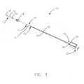
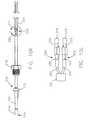
FIG. 1 , a temperature sensor assembly according to the present disclosure is illustrated and generally indicated byreference numeral 10. Thetemperature sensor assembly 10 generally includes atemperature probe 12, which includes a tip cap 14 (preferably a metal alloy) at one end of a probe body 16 (preferably mineral insulated (MI) cable). Amounting connector 18 is secured to theprobe body 16, and acollar 20 is positioned between thetip cap 14 and themounting connector 18. Atransition component 22 covers asecond end 24 of theprobe body 16 and comprises atransition body 27 encapsulating a grommet 23 (not shown inFIG. 1 ; seeFIG. 5 ). The grommet has two channels that enclose connectors that terminate conductors of thetemperature probe 12 to leadwires 26. The specific details of the grommet, its channels, the connectors, and the conductors are illustrated and described in greater detail below. - A
housing 28 receives thelead wires 26 and includes anoutput portion 30 for coupling to a temperature measurement system and providing a temperature characteristic. A circuit assembly (not shown) is enclosed within thehousing 28 and is configured for receiving the temperature signal from thetemperature probe 12 and generating a temperature characteristic in response to the received temperature signal. - The
temperature probe 12 can include a mineral insulated (MI)cable 16 having one or more conductors contained therein or can be a conductor surrounded by a conductor such as a compressed powder. The MI cable can include one or two resistance heating elements or conductors embedded in highly compressed magnesium oxide covered by a copper or an Alloy 825 stainless steel sheath, by way of example. The specification of theMI cable 16 is based, at least in part, on the application requirements and associated conductivity, resistance and sheath material. - The
mounting connector 18 is adapted for securing thetemperature probe 12 to a mounting assembly in an operating environment. Such an arrangement can be as simple as a hanger or can include a nut, flange, rotatable connector, or other device. For example, in some embodiments, the mountingconnector 18 includes a sealing ring orcollar 20 for placing the temperature sensor within a temperature sensing environment that is then sealed by the mountingconnector 18. In one embodiment, the mountingconnector 18 can be a powder metal high strength nut (in the form of a hex nut or other geometry). In such embodiments, the power metal nut can provide for cost effectively securing thetemperature probe 12 in a hostile or enclosed environment, such as within an engine, power plant, fluid flow, or chemical process, by way of example. - The
lead wires 26 include one or more wires that correspond to one or more of the conductors within thetemperature probe 12. Eachlead wire 26 includes afirst end 32 and asecond end 34 and can be stranded or solid wires, among others. Thetransition component 22 is adapted for coupling or aiding in the coupling each of the conductors to an end oflead wire 26, as described in greater detail below. - The
housing 28 also includes aninput portion 36 for receiving an end of thelead wires 26. Theoutput portion 30 of thehousing 28 couples to a temperature measurement system and provides one or more temperature characteristics. A circuit assembly (not shown) is enclosed within thehousing 28 and is configured for receiving the temperature signal from one or more temperature probes 12 (and/or temperature sensors) and generating temperature characteristics in response to the received temperature signals. - The temperature sensor is a thermocouple. In one example, the sensor is a thermocouple that can be formed by coupling the conductors (ungrounded thermocouple) or coupling to the probe body (grounded thermocouple). The temperature signal typically can include a voltage level generated by the thermocouple. In such an example embodiment, a cold junction compensation circuit can be implemented within the probe assembly or within the circuit or
housing 28. The generated temperature characteristic is a characteristic desired and practical for providing information as a function of the temperature signal and as required or desired by the application, namely a resistance value. - The circuit assembly receives the one or more temperature signals from one or more sensors and/or
temperature probes 12 and can generate an output signal or characteristic in response to the signals. These output characteristics can include a ratiometric analog voltage signal (RAVS), a pulse width modulated signal, a variable frequency signal, a variable output impedance, a variable voltage signal, and a variable current signal, by way of example. - In some embodiments, the circuit assembly can be configured for generating a digital signal including the temperature characteristic, wherein the circuit and the housing are each adapted for coupling to a connected component, network, instrument or controller, such as an engine control module. For example, they can be adapted for communication over any well known digital or analog communication facility including a wired or wireless connection. Additionally, by way of example but not intended to be limited thereto, this can include communication protocols such as a controller area network (CAN). CAN is just one example of a well known and widely used communication protocol that can be implemented by the circuit and the housing. Additionally, proprietary interfaces and communications protocols can also be implemented.
- Referring now to
FIGS. 2A and2B , another form of a temperature sensor assembly constructed in accordance with the principles of the present disclosure is illustrated and generally indicated byreference numeral 50. In this form, thelead wires 54 are contained within protective lead covers 58, and the tip caps 60 are in an opposed relationship to sense the temperature of two different areas. Accordingly, thetemperature sensor assembly 50 includes afirst sensor probe 52, asecond sensor probe 53, and anadaptor circuit assembly 62. Eachsensor probe cable 80, containing a temperature sensor (not shown) and one or more conductors coupled to the temperature sensor. Eachsensor probe sensor probe adaptor circuit assembly 62 includes inputs for receiving the temperature signals and anoutput 53 for coupling to a temperature measurement system and providing one or more temperature characteristics responsive to the received temperature signals. A circuit is enclosed within thehousing 56 and is configured with electronic circuit components and software such as computer executable instructions for receiving the temperature signals and generating the temperature characteristics in response to one or more temperature signals. - As shown in
FIG. 2B , the lead covers 58 can be removed in some embodiments as this cover is optional. The lead covers 58 can cover all or only a portion of the leads between the temperature probes 12 andhousing 56. With reference toFIG. 2A , the lead covers 58 are shown extending from thehousing 56, past thetransition components 86, and to an area near thecollars 84. - As shown in
FIGS. 3A and3B , anadaptor circuit assembly 62 is assembled fromdual lead wires 54 that lead toconnectors 70, which pass through thehousing base 72 and into acavity 73 formed in thehousing base 72. Theconnectors 70 are in electrical contact with thecircuit board 66 and itscircuit components 68 in order to provide the temperature signals as previously set forth. Also, thecavity 73 is enclosed by acover 74, which may be a potting compound in another form of the present disclosure or used with a potting compound in yet another form, thus protecting and/or sealing the cavity and the electronics therein. - Referring now to
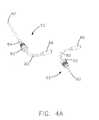
FIGS. 4A to 4C , the twosensor probes lead wires 54. The sensor probes 52, 53 are preferably constructed withcables 80 or constructed sensor tubes having intermediate bends of about 90 degrees from thetip cap 60 to thetransition component 86. The components of the sensor probes 52, 53 include thecable 80, preferably MI and having about a 90 degree bend, a mountingconnector 82, acollar 84, and atransition component 86, thetransition component 86 comprising atransition body 87 and agrommet 88. Thelead wires 54 are coupled through thetransition component 86 for connection to the housing (not shown), which is described in greater detail below. - Turning now to
FIG. 5 , various components of thetemperature sensor assembly 50 are illustrated and described with reference to the sequential assembly thereof. The sensor probes 52, 53 as shown inFIGS. 4A to 4C , by way of example, can be assembled from a selection of components as shown in one exemplary embodiment of an unassembled "kit" inFIG. 5 . The "kit" ofFIG. 5 includesconductors 90,connectors 92,lead wires 54 having leads 55, aninsulator 96, atube 94, atransition component 22/86 comprising atransition body 27/87 and a grommet 23/88, a mountingconnector 18, acollar 20/84, atip cap 14/60, and atip disc 93. The assembly of these components, which may comprise a "kit", will be described below. FIG. 6 illustrates one embodiment ofconnectors 92 that provide for the crimping termination of thetemperature probe conductors 90 and the crimping of the sensor leads 55 to a second opposing end of eachconnector 92. As shown inFIG. 6 , theconnectors 92 may have a straight configuration to provide for an in-line crimp between theleads 55 and theconductors 90. Theconnectors 92, when assembled, each reside within their own channel within thegrommet 88 enclosed within thetransition component 86. In some embodiments, theconnector 92 is composed of a metal that can be welded, so that aconductor 90 and/or awire 54 can be welded to theconnector 92 following compressive engagement with theconnector 92 such as through crimping.- Referring now to
FIGS. 7A to 7L and to the flow chart ofFIG. 8 , various exemplary embodiments of temperature sensor assembly parts of a kit such as the kit ofFIG. 5 , and methods of manufacturing and assembling temperature sensor assemblies are illustrated. FIG. 7A illustrates the unassembled relationship of the formedsensor conductors 90 to theconnectors 92, and theconnectors 92 to thelead wires 26/54.FIG. 7B illustrates the relationship of thesensor conductors 90 after being crimped to theconnectors 92 showing how the forming step maintains a physical separation between each of theconnectors 92.FIG. 7C illustrates the assembly of thesensor conductors 90, theconnectors 92, and thelead wires 26/54 after thelead wires 26/54 are crimped to a second end of eachconnector 92. The other components for thetemperature sensor assembly insulator 96, atube 94, atransition component 22/86 comprising atransition body 27/87 and a grommet 23/88, a mountingconnector 18, acollar 20/84, atip cap 14/60, and atip disc 93. In the paragraphs that follow, a description is given as to how each of these components may be added to the assembly.FIG. 7D illustrates the assembly after attaching theconductors 90 to thewires 54, via theconnectors 92, and placing the attached portions within individual channels of the grommet 23/88, further maintaining a physical separation of theconnectors 92 from each other. In other embodiments, theconductors 90 can be welded or otherwise directly attached to thewires 26/54 and those attachments can be enclosed within the channels of the grommet 23/88. As one exemplary embodiment,FIG. 7E provides cross-sectional details of the grommet 23/88 illustrating theindividual channels 89 within the grommet 23/88 for maintaining the physical separation of theconnectors 92. As shown, thechannels 89 can have a step nature having two portions each coupled in series and each having a different diameter or channel width.FIG. 7F further illustrates an embodiment of a temperature sensor having twosensor conductors 92 attached to connectors (not shown) andwires 26/54 attached to theconnectors 92, with the attachments placed within the steppedchannels 89 of the grommet 23/88. Theconductors 90 ofFIG. 7F are each formed so as to extend in an outward direction from a longitudinal axis, which may help facilitate crimping of theconductors 90 to theconnectors 92.FIG. 7G illustrates the assembly of aninsulator 96 oversensor conductors 90. The probe may comprise atube 94 or sheath that can be assembled on theinsulator 96 in an embodiment where acurved MI cable 80 is not used for the probe body.FIG. 7H illustrates thetransition body 27/87 being assembled over the grommet 23/88 and an end of theinsulator 96.FIG. 7I illustrates the assembly ofFIGS. 7G and7H having thetube 94 positioned over theinsulator 96. Thetransition body 27/87 may be attached to the metal body of thetube 94, such as by welding.FIG. 7J illustrates the mountingconnector 18/82 being rotatably positioned about the body of the probe, which is thetube 94 in this example, andFig. 7K shows thecollar 20/84 being positioned between the sensingend 21 of the probe and the mountingconnector 18/82. Thecollar 20/84 is attached to the probe body (tube 94), such as by welding or other means. Thecollar 20/84 is preferably attached to the surface of the probe body ortube 94 to form an airtight seal in some embodiments. The mountingconnector 18/82 andcollar 20/84 are each adapted for mounting thetemperature probe 12/52 to a mounting surface, such as by screwing the mountingconnector 18/82 into a threaded hole and sealing thecollar 20/84 and mountingconnector 18/82 against the mounting surface, by way of example.FIG. 7L shows the placement of atip cap 14/60 and/or atip disc 93 that can be attached, such as through welding, to the end of themetal probe tube 94 or MI cable to enclose the temperature sensor. In some embodiments, the end of theMI tube 94 or the probe body can be left open and not sealed.- This process is also described in
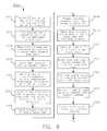
Fig. 8 as one exemplary embodiment of a manufacturing assembly operation. Theprocess 3000 includes astep 3002 of attaching a first wire to a first end of a first conductor and attaching a second wire to a first end of a second conductor, anotherstep 3004 of placing a grommet having a first channel over the attachment of the first wire to the first conductor and having a second channel over the attachment of the second wire to the second conductor, anotherstep 3006 of placing a transition body over the first and second conductors and about the grommet for securing the grommet and attachments within a cavity of the transition body, anotherstep 3008 of inserting each conductor into a channel of an insulator, anotherstep 3010 of joining the first end of the first conductor to the first end of the second conductor to form a thermocouple junction at a first end of the insulator, anotherstep 3014 of attaching the transition body to a second end of a probe body, anotherstep 3016 of positioning a mounting connector about the outer surface of the probe body between a first end and the second end of the probe body, and anotherstep 3018 of attaching a collar to the outer surface of the probe body between the first end of the probe body and the mounting connector. Theprocess 3000 can also include astep 3020 of attaching a second end of the first wire to an input of a housing and attaching a second end of the second wire to an input of the housing. Thisstep 3020 may also include attaching a second end of the first wire to a circuit board; and attaching a second end of the second wire to the circuit board. - In other embodiments, the
process 3000 can include astep 3022 of attaching a cover over the wires, or a portion of the wires. For example, the cover could extend from the transition body or probe to an input of the housing, enclosing a portion of the first and second wires within the cover between the transition body and the housing. In yet other embodiments, theprocess 3000 can include astep 3024 of bending an intermediate portion of the probe body between the transition body and the mounting connector to form an angle, such as a 90 degree angle. - The
process 3000 can also include astep 3026 of connecting the first wire and the second wire to a circuit enclosed within a housing assembly having an input for receiving a second end of the wires, the circuit being configured for receiving a temperature signal from the temperature sensor, for example a thermocouple, and generating the temperature characteristic in response to the received temperature signal. Further, theprocess 3000 may include astep 3028 of connecting an output of the circuit to an output pin of the housing assembly configured for providing the generated temperature characteristic to a temperature measurement system coupled to the output pin. - Referring now to
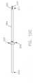
FIG. 9 ,FIGS. 10A to 10N , and to the flow chart ofFIG. 11 , various embodiments of temperature sensor assembly parts (or a kit as shown inFIG. 9 ) and the methods of manufacturing and assembling temperature sensor assemblies (as shown inFIGS. 10A to 10N ) are illustrated, which will now be described. The "kit" ofFIG. 9 includesconductors 290,connectors 292, aMI cable 294, atransition body 227, agrommet 223, a mountingconnector 218, acollar 220, and atip cap 214. The assembly of these components, which may comprise a "kit", will be described below. - As shown in
FIG. 11 , another example of aprocess 3100 of assembling a temperature sensor assembly is illustrated. Theprocess 3100 starts with aMI cable 294 as shown inFIG. 10A , which has an end stripped to expose afirst conductor 290 and asecond conductor 290 as shown inFIG. 10B . Thus, theprocess 3100 includes astep 3102 of stripping a first end of aMI cable 294 to expose first andsecond conductors 290. Theprocess 3100 also includes astep 3104 of forming a thermocouple junction or other temperature sensor or sensing element at asecond end 209 of the mineral insulatedcable 294. InFIG. 10C , acollar 220 is attached about anintermediate portion 208 of the probe body (MI cable 294 in this example). Thus, theprocess 3100 also includes astep 3106 of attaching thecollar 220 about the probe body (MI cable 294). An end of the probe body can also be closed as discussed above and shown by way of example as an attachedtip cap 214 or disc (as shown inFIG. 10D ) or by other means as described above. Thus, theprocess 3100 may include astep 3108 of enclosing thesecond end 209 of the probe body. Theprocess 3100 also includes astep 3110 of positioning a mountingconnector 218 about an outer surface of the probe body (MI cable 294) between thefirst end 211 of the probe body and thecollar 220 as shown inFIG. 10D , and astep 3112 of placing atransition body 227 over thefirst end 211 of the probe body. Theconductors 290 can be formed for crimping or attaching as shown inFIGS. 10E-10F , wherein theconductors 290 are bent so as to be oriented in an outward direction from the longitudinal axis of theMI cable 294. - The
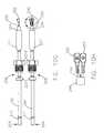
process 3100 further includes astep 3114 of attaching theconductors 290 to exposed wire leads 255 ofwires 254. Theconductors 290 could be connected directly to theleads 255 of thewires 254, or they may be attached by crimping, welding, soldering, other mechanical coupling, or any other suitable coupling as is known to those skilled in the art. Thisstep 3114 can include forming an end of eachconductor 290 for crimping, and as described above, this can include stripping the end of theconductor 290 to expose a conducting portion, bending or shaping the conducting portion to a desired position or shape, and otherwise preparing the conducting portion for compression and/or welding, soldering, or coupling as is known to those skilled in the art. In some embodiments,connectors 292 can be welded, soldered or otherwise coupled to the end of one of theconductors 290. With reference toFIGS. 10G-10H , theconductors 290 are mechanically crimped to theconnectors 292. With reference toFIGS. 10I-10J , the lead ends 255 of thelead wires 254 are also mechanically crimped to theconnectors 292. While crimping the mechanical coupling may be sufficient in some embodiments, in other embodiments the crimped coupling between theconductor 290, thewire 254, and theconnector 292 can also be welded or soldered. For example, with reference toFIGS. 10K-10L , welding or soldering material may be added to theconnector 292 at aportion 295, or to any other suitable portion of theconnector 292. The welding described herein can include any type or method of welding known or developed in the art. In these embodiments, the combination of mechanical coupling via acrimped connector 292 and a welding of theconnector 292 to theconductor 290 and/or to thewire 254 can provide benefits. For example, the combination can provide for improved conductivity, a stronger bond, and decrease failures of this attachment and coupling. - The
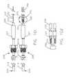
process 3100 also includes astep 3116 of placing agrommet 223 having one or more channels (not shown) over the attachments of thewires 254 to theconductors 290, as shown inFIG. 10M . Theprocess 3100 further includes astep 3118 of sliding thetransition body 227 over thegrommet 223 and attaching thetransition body 227, for example by welding, to an end of the probe body with thetransition body 227 substantially covering thegrommet 223 as shown inFIG. 10N . As described in regard toFigs. 3A and3B above, theprocess 3100 can also include astep 3120 of attaching a second end of the first wire to a circuit board and step 3122 of attaching a second end of the second wire to the circuit board. - Additionally, as described in the example above with regard to
Fig 3 , in some embodiments the method of manufacturing can also include connecting thefirst wire 54 and thesecond wire 54 to a circuit enclosed within ahousing 28 of anadaptor circuit assembly 62 having an input for receiving a second end of thewires 54. As noted above the circuit can be configured withelectronic components 68 and circuits, memory, a processor, and computer executable instructions configured for receiving one or more temperature signals from temperature sensors, such as a thermocouple, thermistor, or RTD, and generating one or more temperature characteristics in response to the received temperature signals. The method can also include connecting anoutput 53 of the circuit to an output connector or pin of theadaptor circuit assembly 62 configured for providing the generated temperature characteristic to a temperature measurement system coupled to the output connector. - As known to those skilled in the art, each of the processes described herein can be repeated to produce one or more probes. After such probes are manufactured, one or more, for example, two probes can be connected to a common circuit for receiving a plurality of temperature signals. In such embodiments, the sensor adaptor circuit can be configured for generating and providing one or more temperature characteristics at the output. Each temperature characteristic can be based on one or more of the temperature signals depending on the desired application and operational environment for the temperature sensor assembly.
- Various benefits are provided by one or more embodiments of the temperature sensor assemblies and methods of manufacturing such temperature sensor assemblies as generally described in this disclosure. One or more of these embodiments can provide for a high compaction construction, an assembly that is high vibration and shock resistance and therefore provides a longer useful life. The temperature sensor assemblies described herein are capable of use in a wide variety of temperature applications including temperature of flames and temperatures of greater than 900 degree Celsius and have been shown to perform well up to temperatures of 1200 degree Celsius through the use of Alloy 600 in the construction. The design and method of construction provides for utilizing either a moderate duty lead wire or up to an extra heavy duty lead wire which is the source of many faults and failures for temperature sensor assemblies. Similarly, the assemblies of the present disclosure can be utilized in a wide variety of temperature sensing applications including low temperature applications such as coolant, brake fluid, inlet air, sea water, and oil temperature.
- In some embodiments more than one
temperature probe 12 can be included in thetemperature sensor assembly 10 or more than one temperature sensor can be included in one or more temperature probes 12. In such cases, one or more of the temperature probes 12 or sensors can provide separate temperature signals to the circuit associated with one or more measured or sensed temperatures. In one such embodiment, the assembly includes a second wire set corresponding to a set ofsecond conductors 90, and asecond transition component 22 for coupling each of thesecond conductors 90 to at least one of thewires 26 of the second wire set. In these cases, thehousing 28 will include asecond input 36 for receiving the second wire set 26. The circuit is adapted to receive the second temperature signals and generate a second temperature characteristic indicative of the temperature about the exterior of thesecond temperature probe 12. - In one embodiment, the
temperature probe 12 is assembled from a mineral insulated cable having conductors, a metal body, and insulating material. In other embodiments, thetemperature probe 12 can be manufactured to include theconductors 90 and thebody 16. In some embodiments, acollar 20 is positioned about an exterior surface of theprobe body 16 and adapted for engaging the fitting to secure thetemperature probe 12 to the mountingassembly 18. Thecollar 20 is attached, such as by welding, to the exterior surface of theprobe body 16. Thecollar 20 can be attached to the exterior surface of theprobe body 16 by any known or future method including laser welding, spin welding, electronic beam welding, resistance welding, and ultrasonic welding, by way of example. - In some embodiments, the
transition component 22 includes a grommet 23 and atransition body 27. The grommet 23 can include one or moreinternal cavities 89 each dimensioned for receiving an end of one of theconductors 90 and for receiving anend 34 of at least one of the at least onewire 26 of the wire set, and thetransition body 27 having a cavity substantially enclosing the grommet 23 and being welded to theprobe body 16. Each of theinternal cavities 89 of the grommet 23 can also be configured to include a first portion and a second portion coupled and positioned in series with the first portion. The second portion can have a cavity width greater than or less than a cavity width of the first portion. - In some embodiments, the
conductors 90/290 are directly connected to thewires 26/54/254 by welding or soldering or other known forms of directly connectingconductors 90/290. In other embodiments, anelectrical connector 92/292 is utilized to couple theconductors 90/290 to thewires 26/54/254. For example, oneelectrical connector 92/292 can include a first end compressively engaging aconductor 90/290 and/or a second end compressively engaging awire 26/54/254. This can be a crimp compression engagement or similar coupling. In such cases, theelectrical connector 92/292 can be positioned within one of theinternal cavities 89 of the grommet 23/223, when provided. In some embodiment, the compressive engagement can be supplemented with a welding or soldering. In such cases, theelectrical connector 92/292 is preferably composed of a weldable material, such as an alloy 42 material, by way of example. In other embodiments, thetransition component 22/86/222 may couple theconductors 90/290 to thewires 26/54/2554 by maintaining a mechanical communication between the wire leads 55/255 and theconductors 90/290. - In some embodiments, the
probe body 16 is formed from ametal tube 94/294. This can aid in the manufacturing process and help reduce costs. In such embodiments, oneend 209 of themetal tube 94/294 can be closed about the temperature sensor by crimping, welding, roll forming and/or swaging anend 209 of themetal tube 94/294. In other embodiments, atip cap 14/60/214 ordisc 93 can be positioned proximate theend 209 of themetal tube 94/294 including the temperature sensor, and can be welded, brazed, or otherwise bonded to theend 209 of themetal tube 94/294 to close theend 209 of themetal tube 94/294 and to seal it for temperature sensing applications. - As noted above, the
probe body 16/80 can be formed, bent or otherwise arranged for mounting on the desired temperature sensing application, For example, theprobe body 16/80 can be bent or formed to have any required angle, and as shown in the examples of some of the figures, has an intermediate portion having an angled portion positioning the first end of theprobe body 80 at about 90 degrees from the second end of theprobe body 80. - In some embodiments, a
cover 58 covering all or a portion of the wire set 54 from thetransition portion 22 orprobe body 16 to thehousing input 36 can be provided to provide an aesthetic or practical benefit to the temperature sensor assembly. For example, in some cases thetemperature sensor assembly cover 58 to be adapted with heat shielding or deflecting material. In other embodiments, it may be desired to protect theleads 55 due to moving parts or a likelihood that the leads 55 may be snagged or pulled in the operating environment. - Each of the sensor probes 12/52/53/212 can include a wire set having one or
more wires 26/54/254 and atransition component 22/86/222 coupled to an end of theprobe body 16/80/94/294. A grommet 23/88/223 having one ormore channels 89 adapted for receiving one or more of theconductors 90/290 and one or more of thewires 26/54/254 provides, at least in part, a transition between the probe assembly and the wire set. The grommet 23/88/223 can also be configured to enclose the coupling of eachwire 26/54/254 to eachconductor 90/290. - In some embodiments, each
sensor probe 12/52/212 can include acollar 20/84/220 attached to the exterior of theprobe body 16/80/94/294 and aconnector 18/82/218 rotatably coupled to theprobe body 16/80/94/294 that is configured to engage thecollar 20/84/220 and to secure thetemperature probe 12/52/212 to a first mounting assembly within the operating environment. - In some embodiments, the leads from the sensor probes 12/52/212 are directly connected to the
adaptor circuit assembly 62 such that the assembly is an integrated unit, e.g., theprobes 12/52/212 are not unpluggable. In such embodiments, the first lead is fixedly coupled to the circuit and the second lead is fixedly coupled to the circuit. Such fixedly coupling preferably includes a coupling mechanism that does not enable the unplugging or otherwise detachment of thewire 26/54/254 from theadaptor circuit assembly 62 oradaptor circuit housing 28. - The
adaptor circuit assembly 62 includes ahousing 28 that can be assembled from two or more portions, can be integrated portions, or can be an integrated or unitary body. In some cases, the wire leads 26/54/254 can be retained by thehousing 28 itself such as an integral portion of the molded assembly. - When describing elements or features and/or embodiments thereof, the articles "a", "an", "the", and "said" are intended to mean that there are one or more of the elements or features. The terms "comprising", "including", and "having" are intended to be inclusive and mean that there may be additional elements or features beyond those specifically described.
- Those skilled in the art will recognize that various changes can be made to the exemplary embodiments and implementations described above without departing from the scope of the disclosure. Accordingly, all matter contained in the above description or shown in the accompanying drawings should be interpreted as illustrative and not in a limiting sense.
- It is further to be understood that the processes or steps described herein are not to be construed as necessarily requiring their performance in the particular order discussed or illustrated. It is also to be understood that each process or step can be repeated more than once and that additional or alternative processes or steps may be employed and still be within the scope of the present disclosure.
Claims (12)
- A temperature sensor assembly (10) comprising:at least one temperature probe (12) having a probe body (16) and a temperature sensor and at least one conductor (90) configured to provide a temperature signal indicative of a temperature over the at least one conductor (90);a wire set having at least one wire (26) corresponding to each of the at least one conductor (90), the at least one wire (26) having a first end and a second end, the first end of the at least one wire (26) being coupled to the at least one conductor (90) at a coupled portion;a transition component (22) surrounding the coupled portion of the at least one conductor (90) and the at least one wire (26) of the wire set; anda mounting connector (18) configured to be secured around the probe body (16) and adapted to secure the temperature probe (12) to a mounting assembly in an operating environment;characterized in that the temperature sensor assembly (10) further comprises:a housing (28) having an input (36) configured to receive the second end of the at least one wire (26) of the wire set; anda circuit (62) enclosed within the housing (28), the circuit (62) being configured to receive the temperature signal from the temperature probe (12) and generate a temperature characteristic providing information as a function of the temperature signal in response to the received temperature signal,wherein the temperature probe (12) is external to the housing (28),in that the housing (28) having an output (30) for coupling to a temperature measurement system that is external to the housing (28) and providing the temperature characteristic;wherein the temperature sensor is a thermocouple and wherein the temperature signal includes a voltage level generated by the thermocouple and wherein the circuit (62) includes a cold junction compensation circuit and wherein the temperature characteristic is a resistance value, andwherein the temperature probe (12) includes a mineral insulated cable having the at least one conductor (90) contained therein, wherein the at least one conductor (90) is two conductors (90), the two conductors (90) being coupled to form a thermocouple junction of the thermocouple.
- The assembly (10) of claim 1 wherein the probe body (16) defines a cavity therein, the temperature sensor being positioned within the cavity and the at least one conductor (90) being positioned within the cavity.
- The assembly (10) of claim 1 wherein the assembly (10) is adapted to connect to a component in communication with one of a controller area network (CAN), an instrument, an engine control module, and a digital communication facility.
- The assembly (50) of claim 1 wherein the temperature probe having a probe body and a temperature sensor and at least one conductor is a first temperature probe (52) having a first probe body (80), a first temperature measuring device and at least one first conductor (90), the assembly (10) further comprising a second temperature probe (53) having a second probe body (80) and a second temperature measuring device and at least one second conductor (90) configured to provide a second temperature signal indicative of a second temperature about an exterior of the second temperature probe (53).
- The assembly (50) of claim 6, further comprising:a second wire set having at least one second wire (54) corresponding to each of the at least one second conductors (90), the at least one second wire (54) being coupled to the at least one second conductor (90) at a second coupled portion; anda second transition component (86) surrounding the second coupled portion of the at least one second conductor (90) and the at least one second wire (54);wherein the housing (28) includes a second input (36) configured to receive the second wire set (54) and wherein the circuit (62) is configured to receive the second temperature signal and generate a second temperature characteristic providing information as a function of the temperature signal and indicative of the temperature about the exterior of the second temperature probe (53), and wherein the output (53) is configured to provide the second temperature characteristic.
- The assembly (10) of claim 1 wherein the mounting connector (18) includes a powdered metal fitting having threads configured to screw the fitting into a threaded mounting assembly.
- The assembly (10) of claim 6 wherein the probe body (16) is metal, the assembly (10) further comprising a collar (20) positioned about an exterior surface of the probe body (16), the collar (20) being configured to engage the fitting to secure the temperature probe (12) to the mounting assembly, and
wherein the collar (20) is attached to the exterior surface of the probe body (16) by a method selected from the group consisting of laser welding, spin welding, electronic beam welding, resistance welding, and ultrasonic welding. - The assembly (10) of claim 1 wherein the transition component (22) includes a grommet (23) and a transition body (27), the grommet (23) including at least one internal cavity (89) dimensioned for receiving an end of one of the at least one conductor (90) and for receiving the first end of the at least one wire (26) of the wire set, and the transition body (27) having a cavity substantially enclosing the grommet (23) and being welded to the probe body (16).
- The assembly (10) of claim 8, further comprising at least one electrical connector (92) coupling the at least one conductor (90) to the at least one wire (26) at the coupled portion,
wherein the at least one internal cavity (89) of the grommet (23) includes a first portion and a second portion coupled in series with the first portion, the second portion having a cavity width greater than a cavity width of the first portion. - The assembly (10) of claim 9 wherein the at least one electrical connector (92) includes a first end compressively engaging the at least one conductor (90) and a second end compressively engaging the at least one wire (26), the at least one electrical connector (92) being positioned within the at least one internal cavity (89) of the grommet (23).
- The assembly (10) of claim 1 wherein the temperature probe (12) has a tip cap (14) positioned proximate to the temperature sensor, the tip cap (14) being welded about a first end of the probe body (16) to enclose the temperature sensor within the probe body (16).
- The assembly (10) of claim 1, further comprising a cover (58) covering at least a portion of the wire set (26).
Priority Applications (2)
| Application Number | Priority Date | Filing Date | Title |
|---|---|---|---|
| EP14169351.5AEP2778638B1 (en) | 2007-06-22 | 2008-06-06 | Temperature sensor assembly |
| ATGM252/2011UAT12799U1 (en) | 2007-06-22 | 2008-06-06 | TEMPERATURE SENSOR ARRANGEMENT AND MANUFACTURING METHOD THEREFOR |
Applications Claiming Priority (2)
| Application Number | Priority Date | Filing Date | Title |
|---|---|---|---|
| US11/767,362US7665890B2 (en) | 2006-06-22 | 2007-06-22 | Temperature sensor assembly and method of manufacturing thereof |
| PCT/US2008/066148WO2009002682A1 (en) | 2007-06-22 | 2008-06-06 | Temperature sensor assembly and method of manufacturing thereof |
Related Child Applications (2)
| Application Number | Title | Priority Date | Filing Date |
|---|---|---|---|
| EP14169351.5ADivisionEP2778638B1 (en) | 2007-06-22 | 2008-06-06 | Temperature sensor assembly |
| EP14169351.5ADivision-IntoEP2778638B1 (en) | 2007-06-22 | 2008-06-06 | Temperature sensor assembly |
Publications (2)
| Publication Number | Publication Date |
|---|---|
| EP2162711A1 EP2162711A1 (en) | 2010-03-17 |
| EP2162711B1true EP2162711B1 (en) | 2014-07-16 |
Family
ID=39735132
Family Applications (2)
| Application Number | Title | Priority Date | Filing Date |
|---|---|---|---|
| EP08770363.3ARevokedEP2162711B1 (en) | 2007-06-22 | 2008-06-06 | Temperature sensor assembly and method of manufacturing thereof |
| EP14169351.5AActiveEP2778638B1 (en) | 2007-06-22 | 2008-06-06 | Temperature sensor assembly |
Family Applications After (1)
| Application Number | Title | Priority Date | Filing Date |
|---|---|---|---|
| EP14169351.5AActiveEP2778638B1 (en) | 2007-06-22 | 2008-06-06 | Temperature sensor assembly |
Country Status (7)
| Country | Link |
|---|---|
| US (1) | US7665890B2 (en) |
| EP (2) | EP2162711B1 (en) |
| JP (4) | JP2010530540A (en) |
| AT (1) | AT12799U1 (en) |
| DE (1) | DE202008018148U1 (en) |
| ES (1) | ES2657974T3 (en) |
| WO (1) | WO2009002682A1 (en) |
Families Citing this family (38)
| Publication number | Priority date | Publication date | Assignee | Title |
|---|---|---|---|---|
| US8059947B2 (en)* | 2007-10-29 | 2011-11-15 | Smiths Medical Asd, Inc. | Environmentally protected thermistor for respiratory system |
| US8303173B2 (en)* | 2007-10-29 | 2012-11-06 | Smiths Medical Asd, Inc. | Dual potting temperature probe |
| EP2406606B1 (en)* | 2009-03-13 | 2019-07-31 | Stoneridge, Inc. | Sensor lead sealing and strain relief |
| DE102009015629A1 (en)* | 2009-04-02 | 2010-10-07 | Areva Np Gmbh | Sealing device for a device for level measurement in a liquid container |
| FI125815B (en) | 2010-10-14 | 2016-02-29 | Janesko Oy | Measuring sensor to measure temperature |
| FI126956B (en)* | 2010-10-14 | 2017-08-31 | Janesko Oy | Method and measurement detector for temperature measurement |
| DE102011103331B3 (en)* | 2011-05-27 | 2012-11-29 | Inor Process Ab | Temperature sensor for a contact thermometer |
| US8651460B2 (en) | 2011-06-01 | 2014-02-18 | The Wiremold Company | Wall grommet for power connection |
| DE102011052809A1 (en)* | 2011-08-18 | 2013-03-14 | Dr. Ing. H.C. F. Porsche Aktiengesellschaft | Mounting arrangement for parking assistance sensor used in motor vehicle, has housing portions that are provided with electrical connection units and guide surfaces which are connected at junction box portion |
| CN103207032A (en)* | 2012-01-13 | 2013-07-17 | 热敏碟公司 | Low-profile temperature sensor probe |
| US8926176B2 (en)* | 2012-07-31 | 2015-01-06 | Pgi International, Ltd. | Modular thermowell and method |
| WO2014041171A2 (en)* | 2012-09-17 | 2014-03-20 | Tesona Gmbh & Co.Kg | High temperature sensor with a moulded protective tube |
| JP2014106040A (en)* | 2012-11-26 | 2014-06-09 | Hitachi-Ge Nuclear Energy Ltd | Ultrasonic measurement system |
| JP5761211B2 (en) | 2013-01-11 | 2015-08-12 | 株式会社デンソー | Pair temperature sensor and manufacturing method thereof |
| WO2015023885A2 (en) | 2013-08-15 | 2015-02-19 | Kohler Co. | Systems and methods for electronically controlling fuel-to-air ratio for an internal combustion engine |
| ITMI20131718A1 (en)* | 2013-10-16 | 2015-04-17 | Italcoppie Sensori S R L | JOINT ASSEMBLY OF ELECTRIC CABLES, AND THERMOCOUPLE SENSOR INCLUDING THIS JOINT |
| FR3027106B1 (en)* | 2014-10-08 | 2016-12-09 | Turbomeca | PROBE FOR MEASURING THE TEMPERATURE REGULATING AT THE OUTPUT OF THE HELICOPTER TURBINE |
| KR101602218B1 (en)* | 2014-12-18 | 2016-03-10 | 두산중공업 주식회사 | Stator slot temperature sensor and assemblying method of the same |
| US10260960B2 (en)* | 2015-12-17 | 2019-04-16 | Honeywell International Inc. | System and method to mitigate abrupt environment temperature disturbances in cold junction of TC/RTD in control systems |
| US10429249B2 (en)* | 2016-05-12 | 2019-10-01 | Cleveland Electric Laboratories | Thermocouple transition body apparatus |
| DE102017111764B4 (en)* | 2016-05-31 | 2025-06-05 | Niterra Co., Ltd. | Multi-channel temperature measuring device |
| WO2018135636A1 (en) | 2017-01-20 | 2018-07-26 | 日本特殊陶業株式会社 | Circuit connection device |
| DE102017222007A1 (en)* | 2017-12-06 | 2019-06-06 | Robert Bosch Gmbh | Connecting device for connecting at least one sensor line to an electrical connection line |
| CN111903002B (en) | 2018-02-19 | 2022-11-04 | 沃特洛电气制造公司 | Compact robust connector assembly for high voltage electric heater |
| EP3769078B1 (en)* | 2018-03-22 | 2024-08-14 | Molex, LLC | System and method of submitting data from individual sensors over a shared cable |
| IT201800004602A1 (en)* | 2018-04-17 | 2019-10-17 | Improved temperature measurement system in a harsh atmosphere with energy saving | |
| CN108955762B (en)* | 2018-06-04 | 2024-03-22 | 唐智科技湖南发展有限公司 | Composite sensor |
| CN108827490A (en)* | 2018-06-15 | 2018-11-16 | 大连博控科技股份有限公司 | High tensile motor temperature sensor |
| JP2020046237A (en)* | 2018-09-18 | 2020-03-26 | 日本特殊陶業株式会社 | Temperature sensor and manufacturing method of temperature sensor |
| FR3088424B1 (en) | 2018-11-08 | 2021-09-24 | Sc2N Sa | TEMPERATURE SENSOR WITH ANTI-ROTATION STOP |
| TWI681174B (en)* | 2018-11-30 | 2020-01-01 | 徐振健 | Multi-point temperature detection device |
| CN111998970A (en)* | 2020-09-02 | 2020-11-27 | 杭州乾龙电器有限公司 | Temperature measuring device for circuit breaker |
| USD1030526S1 (en)* | 2022-03-18 | 2024-06-11 | Therm-O-Disc, Incorporated | Single probe sensor |
| USD1031467S1 (en)* | 2022-03-18 | 2024-06-18 | Therm-O-Disc, Incorporated | Dual probe sensor |
| CN115356113B (en)* | 2022-09-01 | 2024-04-19 | 中国科学院工程热物理研究所 | A device for measuring the outlet temperature and pressure of a compressor in an engine |
| CN115683378B (en)* | 2022-09-08 | 2023-06-09 | 中国科学院合肥物质科学研究院 | Miniature columnar low-temperature sensor material structure |
| JP7668602B2 (en) | 2022-12-23 | 2025-04-25 | 山里産業株式会社 | External wireless transmitter, sensor device and sensor system |
| US12316090B2 (en)* | 2023-03-08 | 2025-05-27 | Pratt & Whitney Canada Corp. | Temperature sensor for arc detection |
Family Cites Families (148)
| Publication number | Priority date | Publication date | Assignee | Title |
|---|---|---|---|---|
| US3963316A (en) | 1972-10-19 | 1976-06-15 | Amp Incorporated | Electrical connector for a printed circuit board |
| DE2427992A1 (en) | 1973-06-13 | 1975-03-13 | Thermal Syndicate Ltd | METHOD OF MEASURING HIGH TEMPERATURES WITH THERMOCOUPLES |
| US3954507A (en) | 1973-06-13 | 1976-05-04 | Dennis Ephraim Carter | Thermocouples used for measuring temperatures |
| US4129351A (en) | 1974-06-20 | 1978-12-12 | Matsushita Electric Industrial Company, Limited | Connector assembly for printed circuit board |
| US3934786A (en) | 1974-11-20 | 1976-01-27 | Jerome Underground Transmission Equipment, Inc. | Method and apparatus for splicing and welding stranded electrical cables |
| US3984912A (en) | 1975-02-28 | 1976-10-12 | Automatic Equipment Development Corporation | Method for splicing cable |
| US3994552A (en) | 1975-10-01 | 1976-11-30 | International Telephone And Telegraph Corporation | Submersible pipe electrical cable assembly |
| US4072394A (en) | 1976-03-01 | 1978-02-07 | The Bendix Corporation | Electrical contact assembly |
| US4120556A (en) | 1976-03-01 | 1978-10-17 | The Bendix Corporation | Electrical contact assembly |
| US4039244A (en) | 1976-04-09 | 1977-08-02 | Coatings Inc. | Bimetallic electrical connector and method for making the same |
| US4066325A (en) | 1976-10-15 | 1978-01-03 | General Motors Corporation | Electrical connector for printed circuit board |
| US4152578A (en) | 1977-10-03 | 1979-05-01 | Emerson Electric Co. | Electric heating elements |
| US4206958A (en) | 1978-03-27 | 1980-06-10 | The Bendix Corporation | Electrical conductor having an integral electrical contact |
| US4392703A (en) | 1978-03-27 | 1983-07-12 | The Bendix Corporation | Electrical conductor having an integral electrical contact |
| US4417395A (en) | 1978-03-27 | 1983-11-29 | The Bendix Corporation | Method of making an electrical conductor having an integral electrical contact |
| US4457570A (en) | 1980-02-12 | 1984-07-03 | Virginia Patent Development Corporation | Connector for mating modular plug with printed circuit board |
| US4252397A (en) | 1979-07-12 | 1981-02-24 | E. I. Du Pont De Nemours And Company | Insulation piercing electric connector bonded to electric conductor |
| US4262983A (en) | 1979-02-08 | 1981-04-21 | Virginia Plastics Company | Circuit board connector for insulated wire |
| US4223968A (en) | 1979-05-08 | 1980-09-23 | Tektronix, Inc. | High-frequency etched circuit board connector |
| US4315662A (en) | 1979-05-25 | 1982-02-16 | Thomas & Betts Corporation | Undercarpet wiring system installation kit |
| US4258974A (en) | 1979-05-25 | 1981-03-31 | Thomas & Betts Corporation | Installation kit for undercarpet wiring system |
| US4273407A (en) | 1979-10-24 | 1981-06-16 | Snuffer Clifton K | Coaxial connector assembly for attachment to circuit board |
| US4332430A (en) | 1979-10-26 | 1982-06-01 | Rockwell International Corporation | Printed circuit board connector |
| US4717217A (en) | 1980-02-12 | 1988-01-05 | Virginia Patent Development Corporation | Connector for mating modular plug with printed circuit board |
| US4352538A (en) | 1980-05-19 | 1982-10-05 | General Motors Corporation | Low profile connector for printed circuit board |
| US4343523A (en) | 1980-05-27 | 1982-08-10 | Ford Motor Company | Printed circuit board edge connector |
| US4431252A (en) | 1980-05-27 | 1984-02-14 | Ford Motor Company | Printed circuit board edge connector |
| US4556265A (en) | 1981-06-29 | 1985-12-03 | Rca Corporation | RF Coaxial-strip line connector |
| US4470100A (en) | 1981-12-21 | 1984-09-04 | Storage Technology Partners | Printed circuit board connector for use in computer systems |
| US4581478A (en) | 1982-04-07 | 1986-04-08 | Pugh Paul F | Gas pressurized cable and conduit system |
| US4461530A (en) | 1982-09-20 | 1984-07-24 | Bendix Corporation | Socket contact for electrical connectors and method of manufacture |
| US4598963A (en) | 1982-11-05 | 1986-07-08 | Bicc Public Limited Company | Circuit board composite connector |
| US4533202A (en) | 1983-09-29 | 1985-08-06 | The Siemon Company | Multiple electrical connector and block with printed circuit board connector clip |
| US4517625A (en) | 1983-11-09 | 1985-05-14 | Lockheed Corporation | Circuit board housing with zero insertion force connector |
| US4641901A (en) | 1984-01-16 | 1987-02-10 | Stewart Stamping Corp. | Printed circuit board jack for modular plug connector terminated cord |
| US4538623A (en) | 1984-04-09 | 1985-09-03 | Medtronic, Inc. | Thread electrode assembly |
| DK291184D0 (en) | 1984-06-13 | 1984-06-13 | Boeegh Petersen Allan | METHOD AND DEVICE FOR TESTING CIRCUIT PLATES |
| US4579406A (en) | 1985-01-11 | 1986-04-01 | D.A.V.I.D. Systems, Inc. | Printed circuit board connector system |
| ZA865383B (en) | 1985-07-19 | 1988-03-30 | Raychem Corp | Tubular article |
| US5070597A (en) | 1985-07-19 | 1991-12-10 | Raychem Corporation | Tubular article |
| US4725399A (en) | 1985-10-18 | 1988-02-16 | Delta M Corporation | Probe with integrated heater and thermocouple pack |
| US4985000A (en) | 1986-09-30 | 1991-01-15 | Minnesota Mining And Manufacturing Co. | Shielded cable termination assembly |
| US4695112A (en) | 1986-12-29 | 1987-09-22 | Chrysler Motors Corporation | Printed circuit board, edgeboard connector therefor |
| US4726775A (en) | 1987-04-29 | 1988-02-23 | Amp Incorporated | Electrical connector and circuit board combination |
| US4894906A (en) | 1987-12-23 | 1990-01-23 | Nicolet Instrument Corporation | Superconductive joint for multifilament superconducting and method of forming |
| US4922607A (en) | 1988-05-25 | 1990-05-08 | Medtronic, Inc. | Method of fabrication an in-line, multipolar electrical connector |
| US4875865A (en) | 1988-07-15 | 1989-10-24 | Amp Incorporated | Coaxial printed circuit board connector |
| US4939454A (en) | 1988-07-26 | 1990-07-03 | Hewlett-Packard Company | Connector system for printed circuit board test facility |
| US4871326A (en) | 1988-08-17 | 1989-10-03 | Amp Incorporated | Electrical harness having one connector intended for circuit board mounting |
| US4871319A (en) | 1988-12-21 | 1989-10-03 | Amp Incorporated | Molded circuit board for ribbon cable connector |
| US4912772A (en) | 1989-03-06 | 1990-03-27 | International Business Machines Corporation | Connector and circuit package apparatus for pin array circuit module and circuit board |
| US4900258A (en) | 1989-06-12 | 1990-02-13 | Amp Incorporated | Multi-port coaxial printed circuit board connector |
| US5215471A (en) | 1989-06-13 | 1993-06-01 | General Datacomm, Inc. | Electrical connectors having tapered spring contact elements for direct mating to holes |
| US5046952A (en) | 1990-06-08 | 1991-09-10 | Amp Incorporated | Right angle connector for mounting to printed circuit board |
| JPH0727572Y2 (en) | 1990-09-11 | 1995-06-21 | ヒロセ電機株式会社 | Electrical connector |
| US5088835A (en) | 1990-12-31 | 1992-02-18 | Gordon Shigezawa | Reusable probe connector apparatus |
| US5241910A (en) | 1991-04-05 | 1993-09-07 | Morton International, Inc. | Universal squib connector for a gas generator |
| US5200574A (en) | 1991-04-05 | 1993-04-06 | Morton International, Inc. | Universal squib connector |
| JPH057947U (en)* | 1991-07-09 | 1993-02-02 | ダイハツ工業株式会社 | Exhaust system mounting sensor mounting device |
| DE9109308U1 (en) | 1991-07-27 | 1992-11-26 | Hoechst Ag, 65929 Frankfurt | Temperature measuring device |
| US5214243A (en) | 1991-10-11 | 1993-05-25 | Endevco Corporation | High-temperature, low-noise coaxial cable assembly with high strength reinforcement braid |
| US5393932A (en) | 1992-02-14 | 1995-02-28 | Minnesota Mining And Manufacturing Company | Wire connector |
| US5369225A (en) | 1993-04-20 | 1994-11-29 | Minnesota Mining And Manufacturing Company | Wire connector |
| FR2687782B1 (en) | 1992-02-21 | 1994-04-29 | Sadis Bruker Spectrospin | COLD JUNCTION COMPENSATION DEVICE FOR THERMOCOUPLE. |
| US5491321A (en) | 1992-02-26 | 1996-02-13 | Tweco Products, Inc. | Welding gun assembly |
| US5188536A (en) | 1992-03-16 | 1993-02-23 | Compaq Computer Corporation | Space-saving insulation displacement type interconnect device for electrically coupling a ribbon connector to a printed circuit board |
| US5364186A (en)* | 1992-04-28 | 1994-11-15 | Luxtron Corporation | Apparatus and method for monitoring a temperature using a thermally fused composite ceramic blackbody temperature probe |
| US5266903A (en) | 1992-06-03 | 1993-11-30 | Capacitec | Shielded connector for making electrical connections to a circuit board in the form of a capacitive probe |
| JP2645629B2 (en) | 1992-07-08 | 1997-08-25 | 矢崎総業株式会社 | Circuit board connector |
| US5649974A (en) | 1992-07-27 | 1997-07-22 | Angeion Corporation | Low profile defibrillation catheter |
| DE9214646U1 (en)* | 1992-10-28 | 1992-12-17 | ULTRAKUST elektronic GmbH, 8375 Ruhmannsfelden | Device for measuring value recording |
| SE503511C2 (en) | 1993-03-25 | 1996-07-01 | Ericsson Telefon Ab L M | Device for connecting a circuit board to a connection plane |
| US5302934A (en) | 1993-04-02 | 1994-04-12 | Therm-O-Disc, Incorporated | Temperature sensor |
| US5370459A (en)* | 1993-06-08 | 1994-12-06 | Claud S. Gordon Company | Surface temperature probe with uniform thermocouple junction |
| US5404760A (en) | 1993-10-27 | 1995-04-11 | Westinghouse Electric Corporation | Blade path thermocouple and exhaust gas extraction probe for combustion turbines |
| US5449234A (en)* | 1993-11-29 | 1995-09-12 | Caterpillar Inc. | Air temperature sensor |
| SE502998C2 (en) | 1994-06-10 | 1996-03-11 | Ericsson Telefon Ab L M | Electrical connector and circuit board |
| DE4431291B4 (en) | 1994-09-02 | 2004-03-25 | Alstom | High temperature probe |
| US5498079A (en)* | 1994-12-23 | 1996-03-12 | Rosemount Inc. | Temperature transmitter |
| JPH08219902A (en)* | 1995-02-17 | 1996-08-30 | Matsushita Electric Ind Co Ltd | High temperature thermistor type temperature sensor and manufacturing method thereof |
| US5857259A (en) | 1995-02-24 | 1999-01-12 | The Wiremold Company | Method for making an electrical connection |
| US5609491A (en) | 1995-03-10 | 1997-03-11 | The Whitaker Corporation | Electrical connector for printed circuit board assembly |
| GB9507187D0 (en) | 1995-04-06 | 1995-05-31 | Amp Gmbh | Contact having an independently supported inner contact arm |
| US5533901A (en) | 1995-05-23 | 1996-07-09 | The Whitaker Corporation | Electrical connector with contact alignment member |
| US5853020A (en) | 1995-06-23 | 1998-12-29 | Widner; Ronald D. | Miniature combination valve and pressure transducer and system |
| US5728149A (en) | 1995-12-20 | 1998-03-17 | Medtronic, Inc. | Integral spiral band electrode for transvenous defibrillation leads |
| US5700090A (en) | 1996-01-03 | 1997-12-23 | Rosemount Inc. | Temperature sensor transmitter with sensor sheath lead |
| US5730607A (en) | 1996-01-23 | 1998-03-24 | Mcdonnell Douglas Corp. | Stacked printed circuit board connector |
| TW312863B (en) | 1996-04-30 | 1997-08-11 | Constant Velocity Transmission Lines Inc | Universal connector |
| US6447305B1 (en) | 1996-05-14 | 2002-09-10 | Miraco, Inc. | Circuit to printed circuit board stored energy connector |
| US5676694A (en) | 1996-06-07 | 1997-10-14 | Medtronic, Inc. | Medical electrical lead |
| EP0813042B1 (en)* | 1996-06-12 | 2007-11-07 | Racine Federated Inc. | Ultrasonic vortex flowmeter having remote signal processing |
| US5878851A (en) | 1996-07-02 | 1999-03-09 | Lord Corporation | Controllable vibration apparatus |
| US5865631A (en) | 1997-04-10 | 1999-02-02 | International Business Machines Corporation | Method for reducing shorts on a printed circuit board edge connector |
| US5954759A (en) | 1997-04-21 | 1999-09-21 | Medtronic, Inc. | Fracture resistant medical electrical lead |
| US6785576B2 (en) | 1997-04-21 | 2004-08-31 | Medtronic, Inc. | Medical electrical lead |
| TW340680U (en) | 1997-05-16 | 1998-09-11 | Molex Taiwan Co Ltd | Lead fastener for electric adapters |
| US5982253A (en) | 1997-08-27 | 1999-11-09 | Nartron Corporation | In-line module for attenuating electrical noise with male and female blade terminals |
| DE19753076C1 (en) | 1997-11-29 | 1999-08-19 | Lumberg Karl Gmbh & Co | Electrical connector, esp. series connector |
| DE19753078C2 (en) | 1997-11-29 | 1999-09-30 | Lumberg Karl Gmbh & Co | Electrical connecting terminal, in particular a modular terminal |
| US6388866B1 (en) | 1998-04-03 | 2002-05-14 | Medtronic, Inc. | Implantable medical device having flat electrolytic capacitor with tailored anode layers |
| US6017238A (en) | 1998-06-09 | 2000-01-25 | The Wiremold Company | Connector assembly and method for making |
| JP3311997B2 (en) | 1998-07-06 | 2002-08-05 | 住友電装株式会社 | connector |
| US6055725A (en) | 1998-08-03 | 2000-05-02 | International Business Machines Corporation | Method for reducing shorts on a printed circuit board edge connector |
| JP3555492B2 (en)* | 1998-09-22 | 2004-08-18 | 株式会社デンソー | Temperature sensor |
| JP3456426B2 (en)* | 1998-11-24 | 2003-10-14 | 住友電気工業株式会社 | Electronic control unit |
| GB2344892B (en) | 1998-12-16 | 2002-11-13 | Solartron Group Ltd | Cold junction compensation for multiple thermocouples |
| US6036508A (en) | 1998-12-21 | 2000-03-14 | Hamilton Sundstrand Corporation | Connector for interconnecting a bus bar to a circuit board |
| US6230406B1 (en) | 1999-01-11 | 2001-05-15 | Electric Motion Company, Inc. | Flexible bond harness and manufacturing method therefor |
| US6217373B1 (en) | 1999-02-19 | 2001-04-17 | The Wiremold Company | Thin-film electrical termination and method for making |
| US6678559B1 (en) | 1999-03-23 | 2004-01-13 | Medtronic, Inc. | Implantable medical device having a capacitor assembly with liner |
| CA2447893C (en) | 1999-04-16 | 2006-06-13 | Leitch Technology Corporation | Circuit board mounting system and releasable connector therefor |
| US6261137B1 (en) | 1999-05-05 | 2001-07-17 | Mcgraw-Edison Company | Conductor connection system |
| JP3365550B2 (en) | 1999-05-07 | 2003-01-14 | 住友電装株式会社 | Shield terminal |
| JP3419709B2 (en) | 1999-05-10 | 2003-06-23 | 住友電装株式会社 | Coaxial cable terminal |
| JP3681044B2 (en) | 1999-06-02 | 2005-08-10 | 矢崎総業株式会社 | Board connector |
| US6565385B1 (en) | 1999-07-21 | 2003-05-20 | Cisco Technology, Inc. | Reducing electromagnetic emissions from a connector coupled to a printed circuit board |
| US6431750B1 (en)* | 1999-12-14 | 2002-08-13 | Sierra Lobo, Inc. | Flexible temperature sensing probe |
| DE19960856A1 (en) | 1999-12-16 | 2001-06-28 | Harting Kgaa | Connectors |
| US6617939B1 (en) | 2000-05-31 | 2003-09-09 | Tyco Electronics Corporation | Cable connector assembly with an equalization circuit board |
| DE20012400U1 (en) | 2000-07-18 | 2001-11-29 | Robert Bosch Gmbh, 70469 Stuttgart | Locking slide for connector parts of electrical connector elements |
| JP2002122486A (en)* | 2000-08-11 | 2002-04-26 | Denso Corp | Mounting structure of temperature sensor |
| US6312280B1 (en) | 2000-10-10 | 2001-11-06 | General Motors Corporation | Flexible circuit board connector having insulation removal mechanism |
| JP4734706B2 (en) | 2000-11-01 | 2011-07-27 | Jsr株式会社 | Electrical resistance measuring connector, circuit board electrical resistance measuring device and measuring method |
| JP4016627B2 (en)* | 2000-11-22 | 2007-12-05 | 株式会社デンソー | Temperature sensor |
| USD454335S1 (en) | 2000-11-24 | 2002-03-12 | Hirose Electric Co., Ltd. | Electrical connector |
| USD454333S1 (en) | 2000-11-28 | 2002-03-12 | Hirose Electric Co., Ltd. | Electrical connector housing |
| JP3678145B2 (en) | 2000-12-22 | 2005-08-03 | 住友電装株式会社 | connector |
| JP3656552B2 (en) | 2001-01-04 | 2005-06-08 | 住友電装株式会社 | Shield terminal |
| JP3501146B2 (en)* | 2001-01-19 | 2004-03-02 | ヘレウス・エレクトロナイト株式会社 | Temperature measuring method and temperature measuring device under noisy environment |
| US6643546B2 (en) | 2001-02-13 | 2003-11-04 | Quetzal Biomedical, Inc. | Multi-electrode apparatus and method for treatment of congestive heart failure |
| DE10109828A1 (en) | 2001-03-01 | 2002-09-05 | Xcellsis Gmbh | Electrical temperature measuring device used for measuring the temperature inside thermally insulated gas generating box comprises temperature sensor arranged in protective tube with metal screw fixed to tube |
| USD486794S1 (en) | 2001-06-19 | 2004-02-17 | Hosiden Corporation | Electrical connecting plug |
| US6592253B2 (en)* | 2001-10-09 | 2003-07-15 | Northrop Grumman Corporation | Precision temperature probe having fast response |
| US6683450B2 (en) | 2001-10-31 | 2004-01-27 | Ssi Technologies, Inc. | Sensor assembly with splice band connection |
| US6540556B1 (en) | 2001-12-17 | 2003-04-01 | Speed Tech Corp. | Electric connector |
| TW520088U (en) | 2001-12-26 | 2003-02-01 | Hon Hai Prec Ind Co Ltd | Electrical connector |
| JP4176360B2 (en) | 2002-03-12 | 2008-11-05 | 住友電装株式会社 | Electrical junction box |
| US6879935B2 (en)* | 2002-04-25 | 2005-04-12 | Sepsensor Inc. | Monitoring system with thermal probe for detection of layers in stratified media |
| US6879741B2 (en)* | 2002-11-04 | 2005-04-12 | C Technologies, Inc | Sampling end for fiber optic probe |
| JP2004212269A (en)* | 2003-01-07 | 2004-07-29 | Ngk Spark Plug Co Ltd | Temperature sensor |
| US6772505B1 (en) | 2003-03-04 | 2004-08-10 | The Goodyear Tire & Rubber Company | Method of assembly an annular antenna to a transponder |
| GB2405476B (en) | 2003-08-27 | 2006-07-19 | Gen Electric | Method, system and apparatus for measuring temperature with cold junction compensation |
| US6942381B2 (en)* | 2003-09-25 | 2005-09-13 | Alcoa Inc. | Molten cryolitic bath probe |
| JP4594007B2 (en)* | 2004-09-02 | 2010-12-08 | 日本特殊陶業株式会社 | Temperature sensor and manufacturing method thereof |
| TWI269031B (en)* | 2005-03-14 | 2006-12-21 | Actherm Inc | Pacifier thermometer structure |
| JP4686304B2 (en)* | 2005-08-25 | 2011-05-25 | 日信工業株式会社 | Electronic device and method for manufacturing electronic device |
| US7312690B1 (en)* | 2006-12-21 | 2007-12-25 | General Electric Company | Temperature sensor |
- 2007
- 2007-06-22USUS11/767,362patent/US7665890B2/enactiveActive
- 2008
- 2008-06-06DEDE202008018148Upatent/DE202008018148U1/ennot_activeExpired - Lifetime
- 2008-06-06EPEP08770363.3Apatent/EP2162711B1/ennot_activeRevoked
- 2008-06-06EPEP14169351.5Apatent/EP2778638B1/enactiveActive
- 2008-06-06ATATGM252/2011Upatent/AT12799U1/ennot_activeIP Right Cessation
- 2008-06-06JPJP2010513323Apatent/JP2010530540A/enactivePending
- 2008-06-06ESES14169351.5Tpatent/ES2657974T3/enactiveActive
- 2008-06-06WOPCT/US2008/066148patent/WO2009002682A1/enactiveApplication Filing
- 2011
- 2011-11-14JPJP2011248271Apatent/JP5779481B2/enactiveActive
- 2015
- 2015-03-05JPJP2015043597Apatent/JP6189887B2/enactiveActive
- 2015-04-03JPJP2015001643Upatent/JP3198066U/ennot_activeExpired - Lifetime
Also Published As
| Publication number | Publication date |
|---|---|
| JP6189887B2 (en) | 2017-08-30 |
| US7665890B2 (en) | 2010-02-23 |
| EP2778638A2 (en) | 2014-09-17 |
| US20080025372A1 (en) | 2008-01-31 |
| JP5779481B2 (en) | 2015-09-16 |
| WO2009002682A1 (en) | 2008-12-31 |
| JP2010530540A (en) | 2010-09-09 |
| AT12799U1 (en) | 2012-11-15 |
| EP2778638B1 (en) | 2017-11-29 |
| EP2778638A3 (en) | 2014-12-10 |
| ES2657974T3 (en) | 2018-03-07 |
| EP2162711A1 (en) | 2010-03-17 |
| JP2012032410A (en) | 2012-02-16 |
| DE202008018148U1 (en) | 2011-12-14 |
| JP2015129767A (en) | 2015-07-16 |
| JP3198066U (en) | 2015-06-11 |
Similar Documents
| Publication | Publication Date | Title |
|---|---|---|
| EP2162711B1 (en) | Temperature sensor assembly and method of manufacturing thereof | |
| US7722362B2 (en) | Sensor adaptor circuit housing incapsulating connection of an input connector with a wire | |
| KR101647169B1 (en) | Sensor lead sealing and strain relief | |
| CN103852109B (en) | The method of integrated temperature sensing element | |
| US20070171959A1 (en) | High-temperature sensor | |
| CN103207032A (en) | Low-profile temperature sensor probe | |
| EP2023106B1 (en) | Improved thermocouple head terminal | |
| EP3339825B1 (en) | High-temperature exhaust sensor | |
| US5616049A (en) | Connector assembly for metal-jacketed lambda probe conductor | |
| EP3872465B1 (en) | Temperature sensor and a method of manufacturing a temperature sensor | |
| EP3557207B1 (en) | Coaxial high temperature thermocouple | |
| WO2003036252A3 (en) | Sensor assembly operating at high temperature and method for mounting same | |
| JPH08219902A (en) | High temperature thermistor type temperature sensor and manufacturing method thereof | |
| CN114136470B (en) | A temperature sensor and an assembly method thereof | |
| CN202547817U (en) | Low profile temperature sensor probe | |
| US7011446B2 (en) | Thermocouple junction box with isolated studs | |
| JP2005069901A (en) | Adaptor terminal for polar cable | |
| JP2001267105A (en) | Thermistor-type composite temperature sensor | |
| JP2005122919A (en) | Heater having temperature measuring element | |
| CZ16379U1 (en) | Connection of structural element with a cable |
Legal Events
| Date | Code | Title | Description |
|---|---|---|---|
| PUAI | Public reference made under article 153(3) epc to a published international application that has entered the european phase | Free format text:ORIGINAL CODE: 0009012 | |
| AK | Designated contracting states | Kind code of ref document:A1 Designated state(s):AT BE BG CH CY CZ DE DK EE ES FI FR GB GR HR HU IE IS IT LI LT LU LV MC MT NL NO PL PT RO SE SI SK TR | |
| AX | Request for extension of the european patent | Extension state:AL BA MK RS | |
| 17P | Request for examination filed | Effective date:20100119 | |
| DAX | Request for extension of the european patent (deleted) | ||
| 17Q | First examination report despatched | Effective date:20110124 | |
| GRAP | Despatch of communication of intention to grant a patent | Free format text:ORIGINAL CODE: EPIDOSNIGR1 | |
| INTG | Intention to grant announced | Effective date:20140207 | |
| GRAS | Grant fee paid | Free format text:ORIGINAL CODE: EPIDOSNIGR3 | |
| GRAA | (expected) grant | Free format text:ORIGINAL CODE: 0009210 | |
| AK | Designated contracting states | Kind code of ref document:B1 Designated state(s):AT BE BG CH CY CZ DE DK EE ES FI FR GB GR HR HU IE IS IT LI LT LU LV MC MT NL NO PL PT RO SE SI SK TR | |
| REG | Reference to a national code | Ref country code:GB Ref legal event code:FG4D | |
| REG | Reference to a national code | Ref country code:CH Ref legal event code:EP | |
| REG | Reference to a national code | Ref country code:IE Ref legal event code:FG4D | |
| REG | Reference to a national code | Ref country code:AT Ref legal event code:REF Ref document number:677920 Country of ref document:AT Kind code of ref document:T Effective date:20140815 | |
| REG | Reference to a national code | Ref country code:DE Ref legal event code:R096 Ref document number:602008033342 Country of ref document:DE Effective date:20140828 | |
| REG | Reference to a national code | Ref country code:NL Ref legal event code:VDEP Effective date:20140716 | |
| REG | Reference to a national code | Ref country code:AT Ref legal event code:MK05 Ref document number:677920 Country of ref document:AT Kind code of ref document:T Effective date:20140716 | |
| REG | Reference to a national code | Ref country code:LT Ref legal event code:MG4D | |
| PG25 | Lapsed in a contracting state [announced via postgrant information from national office to epo] | Ref country code:NO Free format text:LAPSE BECAUSE OF FAILURE TO SUBMIT A TRANSLATION OF THE DESCRIPTION OR TO PAY THE FEE WITHIN THE PRESCRIBED TIME-LIMIT Effective date:20141016 Ref country code:LT Free format text:LAPSE BECAUSE OF FAILURE TO SUBMIT A TRANSLATION OF THE DESCRIPTION OR TO PAY THE FEE WITHIN THE PRESCRIBED TIME-LIMIT Effective date:20140716 Ref country code:SE Free format text:LAPSE BECAUSE OF FAILURE TO SUBMIT A TRANSLATION OF THE DESCRIPTION OR TO PAY THE FEE WITHIN THE PRESCRIBED TIME-LIMIT Effective date:20140716 Ref country code:PT Free format text:LAPSE BECAUSE OF FAILURE TO SUBMIT A TRANSLATION OF THE DESCRIPTION OR TO PAY THE FEE WITHIN THE PRESCRIBED TIME-LIMIT Effective date:20141117 Ref country code:ES Free format text:LAPSE BECAUSE OF FAILURE TO SUBMIT A TRANSLATION OF THE DESCRIPTION OR TO PAY THE FEE WITHIN THE PRESCRIBED TIME-LIMIT Effective date:20140716 Ref country code:FI Free format text:LAPSE BECAUSE OF FAILURE TO SUBMIT A TRANSLATION OF THE DESCRIPTION OR TO PAY THE FEE WITHIN THE PRESCRIBED TIME-LIMIT Effective date:20140716 Ref country code:BG Free format text:LAPSE BECAUSE OF FAILURE TO SUBMIT A TRANSLATION OF THE DESCRIPTION OR TO PAY THE FEE WITHIN THE PRESCRIBED TIME-LIMIT Effective date:20141016 Ref country code:GR Free format text:LAPSE BECAUSE OF FAILURE TO SUBMIT A TRANSLATION OF THE DESCRIPTION OR TO PAY THE FEE WITHIN THE PRESCRIBED TIME-LIMIT Effective date:20141017 | |
| PG25 | Lapsed in a contracting state [announced via postgrant information from national office to epo] | Ref country code:CY Free format text:LAPSE BECAUSE OF FAILURE TO SUBMIT A TRANSLATION OF THE DESCRIPTION OR TO PAY THE FEE WITHIN THE PRESCRIBED TIME-LIMIT Effective date:20140716 Ref country code:PL Free format text:LAPSE BECAUSE OF FAILURE TO SUBMIT A TRANSLATION OF THE DESCRIPTION OR TO PAY THE FEE WITHIN THE PRESCRIBED TIME-LIMIT Effective date:20140716 Ref country code:IS Free format text:LAPSE BECAUSE OF FAILURE TO SUBMIT A TRANSLATION OF THE DESCRIPTION OR TO PAY THE FEE WITHIN THE PRESCRIBED TIME-LIMIT Effective date:20141116 Ref country code:LV Free format text:LAPSE BECAUSE OF FAILURE TO SUBMIT A TRANSLATION OF THE DESCRIPTION OR TO PAY THE FEE WITHIN THE PRESCRIBED TIME-LIMIT Effective date:20140716 Ref country code:NL Free format text:LAPSE BECAUSE OF FAILURE TO SUBMIT A TRANSLATION OF THE DESCRIPTION OR TO PAY THE FEE WITHIN THE PRESCRIBED TIME-LIMIT Effective date:20140716 Ref country code:AT Free format text:LAPSE BECAUSE OF FAILURE TO SUBMIT A TRANSLATION OF THE DESCRIPTION OR TO PAY THE FEE WITHIN THE PRESCRIBED TIME-LIMIT Effective date:20140716 | |
| REG | Reference to a national code | Ref country code:DE Ref legal event code:R026 Ref document number:602008033342 Country of ref document:DE | |
| PG25 | Lapsed in a contracting state [announced via postgrant information from national office to epo] | Ref country code:IT Free format text:LAPSE BECAUSE OF FAILURE TO SUBMIT A TRANSLATION OF THE DESCRIPTION OR TO PAY THE FEE WITHIN THE PRESCRIBED TIME-LIMIT Effective date:20140716 Ref country code:DK Free format text:LAPSE BECAUSE OF FAILURE TO SUBMIT A TRANSLATION OF THE DESCRIPTION OR TO PAY THE FEE WITHIN THE PRESCRIBED TIME-LIMIT Effective date:20140716 Ref country code:RO Free format text:LAPSE BECAUSE OF FAILURE TO SUBMIT A TRANSLATION OF THE DESCRIPTION OR TO PAY THE FEE WITHIN THE PRESCRIBED TIME-LIMIT Effective date:20140716 Ref country code:SK Free format text:LAPSE BECAUSE OF FAILURE TO SUBMIT A TRANSLATION OF THE DESCRIPTION OR TO PAY THE FEE WITHIN THE PRESCRIBED TIME-LIMIT Effective date:20140716 Ref country code:CZ Free format text:LAPSE BECAUSE OF FAILURE TO SUBMIT A TRANSLATION OF THE DESCRIPTION OR TO PAY THE FEE WITHIN THE PRESCRIBED TIME-LIMIT Effective date:20140716 Ref country code:EE Free format text:LAPSE BECAUSE OF FAILURE TO SUBMIT A TRANSLATION OF THE DESCRIPTION OR TO PAY THE FEE WITHIN THE PRESCRIBED TIME-LIMIT Effective date:20140716 | |
| PLBI | Opposition filed | Free format text:ORIGINAL CODE: 0009260 | |
| PLAB | Opposition data, opponent's data or that of the opponent's representative modified | Free format text:ORIGINAL CODE: 0009299OPPO | |
| PLBI | Opposition filed | Free format text:ORIGINAL CODE: 0009260 | |
| 26 | Opposition filed | Opponent name:TEMPERATURMESSTECHNIK GERABERG GMBH/CONTINENTAL AU Effective date:20150416 Opponent name:VALEO SYSTEMES DE CONTROLE MOTEUR Effective date:20150416 | |
| PLAX | Notice of opposition and request to file observation + time limit sent | Free format text:ORIGINAL CODE: EPIDOSNOBS2 | |
| R26 | Opposition filed (corrected) | Opponent name:VALEO SYSTEMES DE CONTROLE MOTEUR Effective date:20150416 Opponent name:TEMPERATURMESSTECHNIK GERABERG GMBH/CONTINENTAL AU Effective date:20150416 | |
| 26 | Opposition filed | Opponent name:VALEO SYSTEMES DE CONTROLE MOTEUR Effective date:20150416 Opponent name:TEMPERATURMESSTECHNIK GERABERG GMBH/CONTINENTAL AU Effective date:20150416 | |
| D26 | Opposition filed (deleted) | ||
| REG | Reference to a national code | Ref country code:DE Ref legal event code:R026 Ref document number:602008033342 Country of ref document:DE Effective date:20150416 | |
| PLAF | Information modified related to communication of a notice of opposition and request to file observations + time limit | Free format text:ORIGINAL CODE: EPIDOSCOBS2 | |
| PG25 | Lapsed in a contracting state [announced via postgrant information from national office to epo] | Ref country code:SI Free format text:LAPSE BECAUSE OF FAILURE TO SUBMIT A TRANSLATION OF THE DESCRIPTION OR TO PAY THE FEE WITHIN THE PRESCRIBED TIME-LIMIT Effective date:20140716 | |
| PLBB | Reply of patent proprietor to notice(s) of opposition received | Free format text:ORIGINAL CODE: EPIDOSNOBS3 | |
| PG25 | Lapsed in a contracting state [announced via postgrant information from national office to epo] | Ref country code:MC Free format text:LAPSE BECAUSE OF FAILURE TO SUBMIT A TRANSLATION OF THE DESCRIPTION OR TO PAY THE FEE WITHIN THE PRESCRIBED TIME-LIMIT Effective date:20140716 | |
| REG | Reference to a national code | Ref country code:CH Ref legal event code:PL | |
| PG25 | Lapsed in a contracting state [announced via postgrant information from national office to epo] | Ref country code:LU Free format text:LAPSE BECAUSE OF FAILURE TO SUBMIT A TRANSLATION OF THE DESCRIPTION OR TO PAY THE FEE WITHIN THE PRESCRIBED TIME-LIMIT Effective date:20150606 | |
| REG | Reference to a national code | Ref country code:IE Ref legal event code:MM4A | |
| PG25 | Lapsed in a contracting state [announced via postgrant information from national office to epo] | Ref country code:LI Free format text:LAPSE BECAUSE OF NON-PAYMENT OF DUE FEES Effective date:20150630 Ref country code:CH Free format text:LAPSE BECAUSE OF NON-PAYMENT OF DUE FEES Effective date:20150630 Ref country code:IE Free format text:LAPSE BECAUSE OF NON-PAYMENT OF DUE FEES Effective date:20150606 | |
| REG | Reference to a national code | Ref country code:FR Ref legal event code:PLFP Year of fee payment:9 | |
| PG25 | Lapsed in a contracting state [announced via postgrant information from national office to epo] | Ref country code:BE Free format text:LAPSE BECAUSE OF FAILURE TO SUBMIT A TRANSLATION OF THE DESCRIPTION OR TO PAY THE FEE WITHIN THE PRESCRIBED TIME-LIMIT Effective date:20140716 | |
| PGFP | Annual fee paid to national office [announced via postgrant information from national office to epo] | Ref country code:DE Payment date:20160601 Year of fee payment:9 Ref country code:GB Payment date:20160601 Year of fee payment:9 | |
| PGFP | Annual fee paid to national office [announced via postgrant information from national office to epo] | Ref country code:FR Payment date:20160516 Year of fee payment:9 | |
| RDAF | Communication despatched that patent is revoked | Free format text:ORIGINAL CODE: EPIDOSNREV1 | |
| STAA | Information on the status of an ep patent application or granted ep patent | Free format text:STATUS: THE PATENT HAS BEEN GRANTED | |
| REG | Reference to a national code | Ref country code:DE Ref legal event code:R064 Ref document number:602008033342 Country of ref document:DE Ref country code:DE Ref legal event code:R103 Ref document number:602008033342 Country of ref document:DE | |
| RDAE | Information deleted related to despatch of communication that patent is revoked | Free format text:ORIGINAL CODE: EPIDOSDREV1 | |
| RDAF | Communication despatched that patent is revoked | Free format text:ORIGINAL CODE: EPIDOSNREV1 | |
| PG25 | Lapsed in a contracting state [announced via postgrant information from national office to epo] | Ref country code:MT Free format text:LAPSE BECAUSE OF FAILURE TO SUBMIT A TRANSLATION OF THE DESCRIPTION OR TO PAY THE FEE WITHIN THE PRESCRIBED TIME-LIMIT Effective date:20140716 | |
| RDAG | Patent revoked | Free format text:ORIGINAL CODE: 0009271 | |
| 27W | Patent revoked | Effective date:20161204 | |
| GBPR | Gb: patent revoked under art. 102 of the ep convention designating the uk as contracting state | Effective date:20161204 | |
| PG25 | Lapsed in a contracting state [announced via postgrant information from national office to epo] | Ref country code:HU Free format text:LAPSE BECAUSE OF FAILURE TO SUBMIT A TRANSLATION OF THE DESCRIPTION OR TO PAY THE FEE WITHIN THE PRESCRIBED TIME-LIMIT; INVALID AB INITIO Effective date:20080606 | |
| STAA | Information on the status of an ep patent application or granted ep patent | Free format text:STATUS: PATENT REVOKED | |
| PG25 | Lapsed in a contracting state [announced via postgrant information from national office to epo] | Ref country code:TR Free format text:LAPSE BECAUSE OF FAILURE TO SUBMIT A TRANSLATION OF THE DESCRIPTION OR TO PAY THE FEE WITHIN THE PRESCRIBED TIME-LIMIT Effective date:20140716 | |
| PG25 | Lapsed in a contracting state [announced via postgrant information from national office to epo] | Ref country code:HR Free format text:LAPSE BECAUSE OF NON-PAYMENT OF DUE FEES Effective date:20140716 |