EP2162067B1 - Method for correcting an acquired medical image and medical imager - Google Patents
Method for correcting an acquired medical image and medical imagerDownload PDFInfo
- Publication number
- EP2162067B1 EP2162067B1EP07826154.2AEP07826154AEP2162067B1EP 2162067 B1EP2162067 B1EP 2162067B1EP 07826154 AEP07826154 AEP 07826154AEP 2162067 B1EP2162067 B1EP 2162067B1
- Authority
- EP
- European Patent Office
- Prior art keywords
- image
- acquired
- along
- patient
- body structure
- Prior art date
- Legal status (The legal status is an assumption and is not a legal conclusion. Google has not performed a legal analysis and makes no representation as to the accuracy of the status listed.)
- Active
Links
Images


Classifications
- A—HUMAN NECESSITIES
- A61—MEDICAL OR VETERINARY SCIENCE; HYGIENE
- A61B—DIAGNOSIS; SURGERY; IDENTIFICATION
- A61B6/00—Apparatus or devices for radiation diagnosis; Apparatus or devices for radiation diagnosis combined with radiation therapy equipment
- A61B6/08—Auxiliary means for directing the radiation beam to a particular spot, e.g. using light beams
- A—HUMAN NECESSITIES
- A61—MEDICAL OR VETERINARY SCIENCE; HYGIENE
- A61B—DIAGNOSIS; SURGERY; IDENTIFICATION
- A61B5/00—Measuring for diagnostic purposes; Identification of persons
- A61B5/103—Measuring devices for testing the shape, pattern, colour, size or movement of the body or parts thereof, for diagnostic purposes
- A61B5/107—Measuring physical dimensions, e.g. size of the entire body or parts thereof
- A61B5/1075—Measuring physical dimensions, e.g. size of the entire body or parts thereof for measuring dimensions by non-invasive methods, e.g. for determining thickness of tissue layer
- A—HUMAN NECESSITIES
- A61—MEDICAL OR VETERINARY SCIENCE; HYGIENE
- A61B—DIAGNOSIS; SURGERY; IDENTIFICATION
- A61B6/00—Apparatus or devices for radiation diagnosis; Apparatus or devices for radiation diagnosis combined with radiation therapy equipment
- A61B6/04—Positioning of patients; Tiltable beds or the like
- A—HUMAN NECESSITIES
- A61—MEDICAL OR VETERINARY SCIENCE; HYGIENE
- A61B—DIAGNOSIS; SURGERY; IDENTIFICATION
- A61B6/00—Apparatus or devices for radiation diagnosis; Apparatus or devices for radiation diagnosis combined with radiation therapy equipment
- A61B6/06—Diaphragms
- A—HUMAN NECESSITIES
- A61—MEDICAL OR VETERINARY SCIENCE; HYGIENE
- A61B—DIAGNOSIS; SURGERY; IDENTIFICATION
- A61B6/00—Apparatus or devices for radiation diagnosis; Apparatus or devices for radiation diagnosis combined with radiation therapy equipment
- A61B6/40—Arrangements for generating radiation specially adapted for radiation diagnosis
- A61B6/4007—Arrangements for generating radiation specially adapted for radiation diagnosis characterised by using a plurality of source units
- A61B6/4014—Arrangements for generating radiation specially adapted for radiation diagnosis characterised by using a plurality of source units arranged in multiple source-detector units
- A—HUMAN NECESSITIES
- A61—MEDICAL OR VETERINARY SCIENCE; HYGIENE
- A61B—DIAGNOSIS; SURGERY; IDENTIFICATION
- A61B6/00—Apparatus or devices for radiation diagnosis; Apparatus or devices for radiation diagnosis combined with radiation therapy equipment
- A61B6/44—Constructional features of apparatus for radiation diagnosis
- A61B6/4429—Constructional features of apparatus for radiation diagnosis related to the mounting of source units and detector units
- A61B6/4435—Constructional features of apparatus for radiation diagnosis related to the mounting of source units and detector units the source unit and the detector unit being coupled by a rigid structure
- A61B6/4441—Constructional features of apparatus for radiation diagnosis related to the mounting of source units and detector units the source unit and the detector unit being coupled by a rigid structure the rigid structure being a C-arm or U-arm
- A—HUMAN NECESSITIES
- A61—MEDICAL OR VETERINARY SCIENCE; HYGIENE
- A61B—DIAGNOSIS; SURGERY; IDENTIFICATION
- A61B6/00—Apparatus or devices for radiation diagnosis; Apparatus or devices for radiation diagnosis combined with radiation therapy equipment
- A61B6/46—Arrangements for interfacing with the operator or the patient
- A61B6/461—Displaying means of special interest
- A61B6/463—Displaying means of special interest characterised by displaying multiple images or images and diagnostic data on one display
- A—HUMAN NECESSITIES
- A61—MEDICAL OR VETERINARY SCIENCE; HYGIENE
- A61B—DIAGNOSIS; SURGERY; IDENTIFICATION
- A61B6/00—Apparatus or devices for radiation diagnosis; Apparatus or devices for radiation diagnosis combined with radiation therapy equipment
- A61B6/58—Testing, adjusting or calibrating thereof
- A61B6/588—Setting distance between source unit and detector unit
- A—HUMAN NECESSITIES
- A61—MEDICAL OR VETERINARY SCIENCE; HYGIENE
- A61B—DIAGNOSIS; SURGERY; IDENTIFICATION
- A61B6/00—Apparatus or devices for radiation diagnosis; Apparatus or devices for radiation diagnosis combined with radiation therapy equipment
- A61B6/50—Apparatus or devices for radiation diagnosis; Apparatus or devices for radiation diagnosis combined with radiation therapy equipment specially adapted for specific body parts; specially adapted for specific clinical applications
- A61B6/505—Apparatus or devices for radiation diagnosis; Apparatus or devices for radiation diagnosis combined with radiation therapy equipment specially adapted for specific body parts; specially adapted for specific clinical applications for diagnosis of bone
Definitions
- the instant inventionrelates to methods for correcting an acquired medical image and to medical imagers.
- the instant inventionis related to a method for correcting an acquired medical image of a patient having an internal body structure, said acquired image having a region of interest showing a representation of said internal body structure, said acquired image having been acquired in a medical imager having a radiation source and a radiation detector spaced from one another along an image-taking direction, and between which the patient is disposed.
- a radiologistwants to have an accurate measurement for a specific body part of the patient, he usually puts spherical beads (or another type of landmarks) of known dimensions on the external surface of the patient, approximately close to the location of the internal body part. Correlation between the known size of the bead and the size of the image of the bead provide the magnification factor at the external surface of the patient close to the specific body part.
- landmarksshows limitations. Positioning landmarks is time consuming, and is sometimes unpleasant for the patient (these landmarks being sometimes located near intimate parts of the body). Further, the landmarks will only provide the magnification factor at the external surface of the patient, which might be far away from the internal body part, in particular, but not only, for obese patients.
- such a methodis characterized in that it comprises:
- the factor to be applied in order to correct magnification issues associated with the acquisitionis known with more accuracy, and accurate images will be provided, which might be the basis for a diagnostic or a quantitative measurement.
- a positioning deviceis used for obtaining the position of the internal body part.
- the position of the positioning device, along the image-taking direction,is well-referenced in the frame of reference of the medical imager, for example by construction of the medical imager, because the positioning device is part of, or a movable part of the imager.
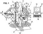
- Figure 1shows a medical imager 1 such as a radiographic apparatus, the apparatus comprising a moving frame 2 displaceable under motor drive along vertical guides 3 in both directions of translation 3a.
- the framesurrounds a field of observation 4 in which a patient P can be placed, e.g. standing, for observing an osteo-articular structure of the patient when in the standing position, which can be important for patients suffering from scoliosis, for example.
- the moving frame 2carries a first radiological source 5 and a first detector 6 which is placed facing the source 5 beyond the field 4, and which comprises at least one horizontal line 6a of detector cells.
- the detector 6may be a gas detector responsive to low doses of radiation, e.g. as described in documents FR-A-2 749 402 or FR-A-2 754 068 .
- other types of detectorsmay optionally be used in the context of the present invention.
- the radiological source 5is adapted to emit ionizing radiation, in particular X-rays, suitable for being detected by the detector 6 in a first image-taking direction 7 that is antero-posterior relative to the patient P, the rays passing through a horizontal slit 8 made through an aiming mask 9 such as a metal plate in order to generate a horizontal beam 10 of ionizing radiation in the field of observation 4.
- ionizing radiationin particular X-rays
- the moving frame 2also carries a second radiological source 11 similar to the source 5 and a second detector 12 similar to the detector 6, disposed facing the source 11 beyond the field 4, and comprising at least one horizontal line 12a of detector cells.
- the radiological source 11is adapted to emit ionizing radiation in a second image-taking direction 13 that is lateral relative to the patient P, passing through a horizontal slit 14 formed in an aiming mask 15 such as a metal plate in order to generate a horizontal beam 16 of ionizing radiation in the field of observation 4.
- radiological sources and detectorsthere could be more than two radiological sources and detectors, and the image-taking directions of these various radiological sources could, where appropriate, be other than mutually perpendicular, and they need not even be horizontal.
- the two detectors 6, 12are connected to a computerized system 37 or some other electronic control system fitted with:
- the microcomputer 37may also be connected to the motor-driven drive means (not shown) contained in the guide 3, and to the sources 5 and 11, so as to control vertical displacement of the frame and the emission of ionizing radiation.
- the medical imagerfurther comprises a positioning device for detecting a position of an internal body structure of the patient.
- the nature of the positioning devicecould vary, and three different embodiments are described here. Although the three different embodiments are represented on the same medical imager, it is understood that a medical imager could comprise only one, or two of these (or other) positioning devices.
- the positioning devicecomprises the second source 11 and detector 12 themselves, as will be explained in detail below, and is used for detecting the position of the internal body structure along the first image-taking direction.
- the positioning devicecomprises a calibrated grid 21 which is drawn, for example on the floor of the imager.
- the grid 21comprises for example one first set of parallel lines 22, perpendicular to the first image-taking direction, and equally spaced from each other, for example by a given distance. These lines will be referenced in the frame of reference of the imager. For example, the distance from each line to a reference line corresponding to the position of the first source 5 along the first image-taking direction is known by construction of the imager.
- Visual inspection by the practitionerwill enable to determine the position of the internal body structure of interest.
- the practitionercan evaluate the approximate position of the internal body structure of interest. By drawing a vertical line passing through this estimated position, the crossing of the vertical line with one line of the first set of lines 22 will provide the position of the internal body structure along the first image-taking direction.
- This positioncan be recorded in the computer by the practitioner, for example with the keyboard. He can input different position values for different body structures.
- the floor grid 21will comprise a second set of lines extending parallel to each other, and perpendicular to the second image-taking direction, and referenced with respect to a line corresponding to the second source 11, which enable to define a position along the second image-taking direction with respect to the second source 11.
- the positioning devicecomprises an auxiliary emitter 28, such as a LASER or else, able to emit a visible beam 29 which will provide a visible spot 30 on the external surface of the patient.
- the auxiliary emitter 28is carried by the structure of the imager, with a known position with respect to the structure of the imager along the first image-taking direction.
- the orientation of the LASER with respect to the first image-taking directionis fixed, and the LASER is translatable, by motorized means, with respect to the structure of the medical imager, along the first image-taking direction.
- the LASERmight be rotatable about the first image-taking direction to sweep along the height of the patient.
- the input means of the computer 37By using for example the input means of the computer 37, using anatomical knowledge, a practitioner will move the LASER beam 24 until the LASER spot will point directly on the internal body structure. The position of the LASER along the first image-taking direction at that time is well known and can be recorded inside the computer.
- This lateral positionwill be used for correcting the frontal image.
- a similar LASERcould be used to determine a frontal position of an anatomical structure of the patient for correcting the lateral image.
- the above-described apparatusoperates as follows:
- the microcomputer 37is used initially to take two radiographic images of the patient P by causing the field of observation 4 to be scanned by the beams 10 and 16 of ionizing radiation over a height corresponding to the structure of the patient that is to be observed, for example the spine and the pelvis, or indeed the entire skeleton.
- the frameis preferably displaceable over a height of not less than 70 centimetres (cm), and preferably over at least one meter.
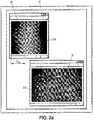
- two calibrated digital radiographic images of the portion of the patient under examinationare stored in the memory of the microcomputer 37, for example an antero-posterior image 31 and a lateral image 32 respectively, which images can be viewed on the screen 19 of the microcomputer, as shown in Figure 2a .
- Bi-dimensional detection data of the structuresuch as an antero-posterior and a lateral radiographs obtained by the apparatus of Fig. 1 , is displayed on a screen 19 of the computerized system 37 as shown on Fig. 2a.
- Fig. 2ashows the real detection data obtained with the image
- Fig. 5ais a schematic representation of the anatomical features of interest, Fig. 5a being for explanatory purposes for the present application, but not obtained by the medical imager itself. It should be understood that detection data such as the radiographs of Fig. 2a , do not necessarily provide with such a clear representation of the structure as shown on Fig. 5a .
- Representations (projections) of an internal body structure (for example the left femoral head 23) of the patientare identified by reference number 23b on the frontal image (right side of Fig. 2a ), and 23a on the lateral image (left side of Fig.2a ).
- the frontal image 31will now be corrected by using the position information obtained by the positioning device. For example, the frontal image 31 will be corrected so that the left femoral head 23 (identified by its representation 23a, 23b on the images) is accurately resized.
- the position of the image of the left femoral head in the second image 32is determined, either manually by the practitioner or automatically by image processing.
- a distance D 23a from the centre of the image of the object to the edge of the imagecan be measured. Since the spatial relationship of the edge of the image acquired by the second detector to the first source and the first detector are known by the construction of the imager, this will provide the position of the image of the object along the first image-taking direction in the imager's frame of reference.
- the position of interest for the object itself with reference to the source 5 along the first image-taking directioncan be estimated from D 23a . It could be simply interpolated in view of the global position of the body along the second image-taking direction, or more accurately using the first image 31 to estimate where, along the line joining point 23a to the source 11, the left femoral head is located.
- the positionis used for resizing the image.
- O 2 M ′ / O 2 MA ′ B ′ / AB , where O 2 is the source 5, M' is the middle position of the internal body structure, M is the image of the middle position of the internal body structure, AB is the width of the detector, and A'B' is the width of the part of the patient at the level of M' which can be visualized by the detector.
- ABis known from the size of the detector
- O 2 Mis known from the source-to-detector distance
- O 2 M'is known from the above-calculated position (by either of the mentioned-methods, alone or in combination). Knowing AB, O 2 M and O 2 M', the Thales formula enables to calculate the real distance A'B', hence the magnification factor for this depth (position along the first image-taking direction) of the image.
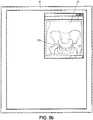
- the corrected image 33is shown on Fig. 2b (or schematic representation on Fig. 5b ).
- the lateral imageprovides anatomical objects which are at different positions along the first image-taking direction
- the corrected imagecan be used by a clinician in a measuring method, whereby a geometrical parameter (length, radius, angle) of an internal body structure is accurately measured on the corrected image(s). This parameter could be used for establishing a diagnostic.
- the same methodcan be implemented for the second image 32, whereby the lateral position of the femoral head is estimated from the first image 31 for providing a correctly magnified image from the second image 32.
- the two obtained imagescan then be used in a three-dimensional reconstruction method, whereby a three-dimensional model, obtained from a previously-acquired knowledge base of similar vertebra, for example memorized in the computer, is placed and sized so as to best fit with the corrected images.
- the acquisitionis performed by a fan beam, so that magnification correction need to be performed only on the image's width.
- the present inventionhas been presented with an embodiment which simultaneously acquires two orthogonal images by scanning. Simultaneous acquisition ensures that the patient will not have moved between the antero-posterior and the lateral acquisitions.
- the two imageswill be orthogonal, nor that they will be acquired simultaneously.
- the second and third embodiments of the inventioncan be implemented with a medical imager having only one source and one detector, and acquiring only one image.
Landscapes
- Health & Medical Sciences (AREA)
- Life Sciences & Earth Sciences (AREA)
- Engineering & Computer Science (AREA)
- Medical Informatics (AREA)
- Heart & Thoracic Surgery (AREA)
- Molecular Biology (AREA)
- Biophysics (AREA)
- Veterinary Medicine (AREA)
- Public Health (AREA)
- Pathology (AREA)
- General Health & Medical Sciences (AREA)
- Biomedical Technology (AREA)
- Physics & Mathematics (AREA)
- Animal Behavior & Ethology (AREA)
- Surgery (AREA)
- High Energy & Nuclear Physics (AREA)
- Radiology & Medical Imaging (AREA)
- Optics & Photonics (AREA)
- Nuclear Medicine, Radiotherapy & Molecular Imaging (AREA)
- Human Computer Interaction (AREA)
- Dentistry (AREA)
- Oral & Maxillofacial Surgery (AREA)
- Apparatus For Radiation Diagnosis (AREA)
- Image Processing (AREA)
Description
- The instant invention relates to methods for correcting an acquired medical image and to medical imagers.
- In particular, the instant invention is related to a method for correcting an acquired medical image of a patient having an internal body structure, said acquired image having a region of interest showing a representation of said internal body structure, said acquired image having been acquired in a medical imager having a radiation source and a radiation detector spaced from one another along an image-taking direction, and between which the patient is disposed.
- In planar imaging, there always is a magnification depending on the geometry of the radiation beam emitted by the source, the mode of projection and the position of the patient and/or the position of the region of interest inside the patient. Radiologists and orthopaedists are used to make some measurements on radiographs. However, most of the time, these measurements are approximate because the clinicians do not know accurately the factor of magnification associated with the radiographs. In fact, as the radiologist technician does not know accurately the position of the patient in the depth of the beam, he cannot provide accurately the magnification factor associated with the image.
- Thus, when a radiologist wants to have an accurate measurement for a specific body part of the patient, he usually puts spherical beads (or another type of landmarks) of known dimensions on the external surface of the patient, approximately close to the location of the internal body part. Correlation between the known size of the bead and the size of the image of the bead provide the magnification factor at the external surface of the patient close to the specific body part.
- However, the use of landmarks shows limitations. Positioning landmarks is time consuming, and is sometimes unpleasant for the patient (these landmarks being sometimes located near intimate parts of the body). Further, the landmarks will only provide the magnification factor at the external surface of the patient, which might be far away from the internal body part, in particular, but not only, for obese patients.
- For all these reasons, one strives to limit the use of landmarks for correcting the magnification factor of a medical imager.
- In
US 2002/0141540 , it is disclosed a C-arm determining a magnification factor of one of the images as a function of the angular displacement of the source and of the recording means between the acquisitions of the images in question. - In
WO 96/11633 - To this aim, according to the invention, such a method is characterized in that it comprises:
- (a)obtaining, from the acquired image, a corrected image taking into account a position of the internal body structure along the image-taking direction.
- By using the position of the internal body structure along the image-taking direction, rather than the position of the external surface of the patient close to the internal body structure, the factor to be applied in order to correct magnification issues associated with the acquisition is known with more accuracy, and accurate images will be provided, which might be the basis for a diagnostic or a quantitative measurement.
- In some embodiments, one might also use one or more of the features as defined in the dependant claims.
- In particular, a positioning device is used for obtaining the position of the internal body part. The position of the positioning device, along the image-taking direction, is well-referenced in the frame of reference of the medical imager, for example by construction of the medical imager, because the positioning device is part of, or a movable part of the imager.
- Other characteristics and advantages of the invention will readily appear from the following description of one of its embodiments, provided as a non-limitative example, and of the accompanying drawings.
- On the drawings :
Fig. 1 is a perspective view of a medical imager,Fig. 2a is a view of the acquired images on the display screen ofFig. 1 ,Fig. 2b is a view of one of the images ofFig. 2a after correction,Fig. 3 is a schematic top view of the apparatus ofFig. 1 , andFig. 4 is a schematic top view corresponding to the view ofFig. 3 ,Fig. 5a ,5b are schematic views corresponding toFigs. 2a ,2b respectively.- On the different Figures, the same reference signs designate like or similar elements.
Figure 1 shows amedical imager 1 such as a radiographic apparatus, the apparatus comprising a movingframe 2 displaceable under motor drive along vertical guides 3 in both directions of translation 3a.- The frame surrounds a field of
observation 4 in which a patient P can be placed, e.g. standing, for observing an osteo-articular structure of the patient when in the standing position, which can be important for patients suffering from scoliosis, for example. - The moving
frame 2 carries a firstradiological source 5 and afirst detector 6 which is placed facing thesource 5 beyond thefield 4, and which comprises at least onehorizontal line 6a of detector cells. By way of example, thedetector 6 may be a gas detector responsive to low doses of radiation, e.g. as described in documentsFR-A-2 749 402 FR-A-2 754 068 - The
radiological source 5 is adapted to emit ionizing radiation, in particular X-rays, suitable for being detected by thedetector 6 in a first image-taking direction 7 that is antero-posterior relative to the patient P, the rays passing through a horizontal slit 8 made through an aimingmask 9 such as a metal plate in order to generate a horizontal beam 10 of ionizing radiation in the field ofobservation 4. - The moving
frame 2 also carries a secondradiological source 11 similar to thesource 5 and asecond detector 12 similar to thedetector 6, disposed facing thesource 11 beyond thefield 4, and comprising at least onehorizontal line 12a of detector cells. - The
radiological source 11 is adapted to emit ionizing radiation in a second image-takingdirection 13 that is lateral relative to the patient P, passing through a horizontal slit 14 formed in an aimingmask 15 such as a metal plate in order to generate ahorizontal beam 16 of ionizing radiation in the field ofobservation 4. - Naturally, there could be more than two radiological sources and detectors, and the image-taking directions of these various radiological sources could, where appropriate, be other than mutually perpendicular, and they need not even be horizontal.
- The two
detectors computerized system 37 or some other electronic control system fitted with: - an input interface comprising at least a
keyboard 18 and generally also a mouse (not shown); - an output interface comprising at least a
screen 19 ; - a
processor 17 for executing a computer program adapted to implement the method described herein. - The
microcomputer 37 may also be connected to the motor-driven drive means (not shown) contained in the guide 3, and to thesources - The medical imager further comprises a positioning device for detecting a position of an internal body structure of the patient. The nature of the positioning device could vary, and three different embodiments are described here. Although the three different embodiments are represented on the same medical imager, it is understood that a medical imager could comprise only one, or two of these (or other) positioning devices.
- According to an embodiment, the positioning device comprises the
second source 11 anddetector 12 themselves, as will be explained in detail below, and is used for detecting the position of the internal body structure along the first image-taking direction. - According to an alterntive not claimed, the positioning device comprises a
calibrated grid 21 which is drawn, for example on the floor of the imager. Thegrid 21 comprises for example one first set ofparallel lines 22, perpendicular to the first image-taking direction, and equally spaced from each other, for example by a given distance. These lines will be referenced in the frame of reference of the imager. For example, the distance from each line to a reference line corresponding to the position of thefirst source 5 along the first image-taking direction is known by construction of the imager. - Visual inspection by the practitioner will enable to determine the position of the internal body structure of interest. By using anatomical knowledge, the practitioner can evaluate the approximate position of the internal body structure of interest. By drawing a vertical line passing through this estimated position, the crossing of the vertical line with one line of the first set of
lines 22 will provide the position of the internal body structure along the first image-taking direction. This position can be recorded in the computer by the practitioner, for example with the keyboard. He can input different position values for different body structures. - Possibly, the
floor grid 21 will comprise a second set of lines extending parallel to each other, and perpendicular to the second image-taking direction, and referenced with respect to a line corresponding to thesecond source 11, which enable to define a position along the second image-taking direction with respect to thesecond source 11. - According to an alternative not claimed, the positioning device comprises an
auxiliary emitter 28, such as a LASER or else, able to emit avisible beam 29 which will provide avisible spot 30 on the external surface of the patient. Theauxiliary emitter 28 is carried by the structure of the imager, with a known position with respect to the structure of the imager along the first image-taking direction. The orientation of the LASER with respect to the first image-taking direction is fixed, and the LASER is translatable, by motorized means, with respect to the structure of the medical imager, along the first image-taking direction. Also, the LASER might be rotatable about the first image-taking direction to sweep along the height of the patient. - By using for example the input means of the
computer 37, using anatomical knowledge, a practitioner will move the LASER beam 24 until the LASER spot will point directly on the internal body structure. The position of the LASER along the first image-taking direction at that time is well known and can be recorded inside the computer. - This lateral position will be used for correcting the frontal image. A similar LASER could be used to determine a frontal position of an anatomical structure of the patient for correcting the lateral image.
- The above-described apparatus operates as follows:
Themicrocomputer 37 is used initially to take two radiographic images of the patient P by causing the field ofobservation 4 to be scanned by thebeams 10 and 16 of ionizing radiation over a height corresponding to the structure of the patient that is to be observed, for example the spine and the pelvis, or indeed the entire skeleton. For this purpose, the frame is preferably displaceable over a height of not less than 70 centimetres (cm), and preferably over at least one meter. - During this movement, two calibrated digital radiographic images of the portion of the patient under examination are stored in the memory of the
microcomputer 37, for example an antero-posterior image 31 and alateral image 32 respectively, which images can be viewed on thescreen 19 of the microcomputer, as shown inFigure 2a . - These images are directly calibrated, since the source-to-detector distance is well known and fixed by construction of the medical imager. Thus, the bi-dimensional coordinates of a pixel of the detector (image frame of reference) are directly related to its tridimensional coordinates in the imager's frame of reference.
- Bi-dimensional detection data of the structure, such as an antero-posterior and a lateral radiographs obtained by the apparatus of
Fig. 1 , is displayed on ascreen 19 of thecomputerized system 37 as shown onFig. 2a. Fig. 2a shows the real detection data obtained with the image, andFig. 5a is a schematic representation of the anatomical features of interest,Fig. 5a being for explanatory purposes for the present application, but not obtained by the medical imager itself. It should be understood that detection data such as the radiographs ofFig. 2a , do not necessarily provide with such a clear representation of the structure as shown onFig. 5a . Representations (projections) of an internal body structure (for example the left femoral head 23) of the patient are identified byreference number 23b on the frontal image (right side ofFig. 2a ), and 23a on the lateral image (left side ofFig.2a ). - The
frontal image 31 will now be corrected by using the position information obtained by the positioning device. For example, thefrontal image 31 will be corrected so that the left femoral head 23 (identified by itsrepresentation - According to the embodiment, the position of the image of the left femoral head in the
second image 32 is determined, either manually by the practitioner or automatically by image processing. A distance D23a from the centre of the image of the object to the edge of the image can be measured. Since the spatial relationship of the edge of the image acquired by the second detector to the first source and the first detector are known by the construction of the imager, this will provide the position of the image of the object along the first image-taking direction in the imager's frame of reference. - The position of interest for the object itself with reference to the
source 5 along the first image-taking direction can be estimated from D23a. It could be simply interpolated in view of the global position of the body along the second image-taking direction, or more accurately using thefirst image 31 to estimate where, along theline joining point 23a to thesource 11, the left femoral head is located. - The position is used for resizing the image. As is known from the Thales formula (see
Fig. 4 ):
source 5, M' is the middle position of the internal body structure, M is the image of the middle position of the internal body structure, AB is the width of the detector, and A'B' is the width of the part of the patient at the level of M' which can be visualized by the detector. - AB is known from the size of the detector, O2M is known from the source-to-detector distance, and O2M' is known from the above-calculated position (by either of the mentioned-methods, alone or in combination). Knowing AB, O2M and O2M', the Thales formula enables to calculate the real distance A'B', hence the magnification factor for this depth (position along the first image-taking direction) of the image. The corrected
image 33 is shown onFig. 2b (or schematic representation onFig. 5b ). - Further, different corrected images could be obtained, for different anatomical features of interest having different positions along the first image-taking direction.
- Furthermore, it should be noted that, since the lateral image provides anatomical objects which are at different positions along the first image-taking direction, it is possible to vertically deal the first image in different regions of interest, each comprising an anatomical objects of interest, and to apply a different magnification factor for each region of interest, each corresponding to the corresponding position along the first image-taking direction of the given anatomical object. This would provide an image for which the magnification would be correct for all the anatomical objects of interest.
- The corrected image can be used by a clinician in a measuring method, whereby a geometrical parameter (length, radius, angle) of an internal body structure is accurately measured on the corrected image(s). This parameter could be used for establishing a diagnostic.
- Of course, in the case of the apparatus of
Figure 1 , the same method can be implemented for thesecond image 32, whereby the lateral position of the femoral head is estimated from thefirst image 31 for providing a correctly magnified image from thesecond image 32. - The two obtained images can then be used in a three-dimensional reconstruction method, whereby a three-dimensional model, obtained from a previously-acquired knowledge base of similar vertebra, for example memorized in the computer, is placed and sized so as to best fit with the corrected images.
- With the medical imager which has been described, the acquisition is performed by a fan beam, so that magnification correction need to be performed only on the image's width.
- The present invention has been presented with an embodiment which simultaneously acquires two orthogonal images by scanning. Simultaneous acquisition ensures that the patient will not have moved between the antero-posterior and the lateral acquisitions.
- Yet, it is not compulsory for the invention that the two images will be orthogonal, nor that they will be acquired simultaneously. Further, the second and third embodiments of the invention can be implemented with a medical imager having only one source and one detector, and acquiring only one image.

Claims (9)
- Method for correcting an acquired medical image of a patient having an internal body structure, said acquired image (31) having a region of interest showing a representation (23b) of said internal body structure (23), said acquired image having been acquired in a medical imager having a first radiation source (5) and a first radiation detector (6) spaced from one another along a first image-taking direction (7), and between which the patient is disposed,
and, wherein acquiring said acquired medical image is performed by moving simultaneously said first source (5) and said first detector (6) along a scanning direction orthogonal to the image-taking direction,
characterized in that :said medical imager having a second radiation source (11) and a second radiation detector (12) spaced from one another along a second image-taking direction (13),wherein said scanning direction is a vertical scanning direction,wherein said second acquired medical image is performed by moving simultaneously said second source (11) and said second detector (12) along said vertical scanning direction orthogonal to the second image-taking direction,andin that the method comprises:
b) obtaining a position of the internal body structure (23) along the first image-taking direction,by a positioning device (11, 12; 28; 21) of known geometric relationship with respect to said first source (5) and first detector (6) along said first image-taking direction(7), the positioning device comprising the second source (11) and the second detector (12) themselves and being used for detecting the position of the internal body structure along the first image-taking direction (7),and said position being used for resizing the acquired image by calculating a magnification factor for said position along the first image-taking direction of the acquired image,a) obtaining, from the acquired image, a corrected image (33)taking into account said position of the internal body structure (23) along the first image-taking direction,wherein said acquired medical image is a first acquired medical image acquired along the first image-taking direction, and wherein at step b), said position is obtained from a second acquired medical image (32) of the patient, the second acquired image having a region of interest showing a representation (23a) of said internal body structure (23), the second image having been acquired along said second image-taking direction (13) different from the first image-taking direction (7),and optionally, wherein said first and second image-taking directions are orthogonal,and wherein said medical imager comprises a frame surrounding a field of observation (4) in which a patient (P) can be placed, standing, for observing an osteo-articular structure of the patient (P) when in the standing position,and, wherein said first radiation detector (6) comprises at least one horizontal line (6a) of detector cells,and wherein said first radiation source (5) is adapted to emit ionizing radiation passing through a horizontal slit (8) in order to generate a horizontal beam (10) of ionizing radiation in said field of observation (4),and wherein said second radiation detector (12) comprises at least one horizontal line (12a) of detector cells,and wherein said second radiation source (11) is adapted to emit ionizing radiation passing through a horizontal slit (14) in order to generate a horizontal beam (16) of ionizing radiation in said field of observation (4) . - Method according to claim 1 wherein step a) includes calculating a distance along the first image-taking direction between a position of the source (5) while acquiring the first image and said position of the internal body structure (23), and using a distance between said position of the source (5) and a position of the detector (6) while acquiring the first image along the first image-taking direction.
- Method according to any preceding claim, wherein said internal body structure (23) is a first internal body structure at a first position along said first image-taking direction, wherein the patient has a second internal body structure, said first acquired image having a second region of interest showing a representation of said second internal body structure, wherein, step a) comprises obtaining, from the first acquired image, the corrected image also taking into account the second position of the second internal body structure along the first image-taking direction, the first and second positions along the first image taking direction being different from one another.
- Method according to any preceding claim wherein the corrected image obtained at step a) is a first corrected image of an internal body structure at a first position along the first image-taking direction, the method further comprising the step a') of obtaining, from the first acquired image, a second corrected image taking into account a second position of the internal body structure along the first image-taking direction, the first and second positions being different from one another.
- Method for reconstruction of a patient-specific three-dimensional model comprising:- obtaining at least one corrected image (33) of a patient using a method according to any of the preceding claims,- obtaining a patient-specific three-dimensional model from said at least one corrected image and an a priori knowledge base of the internal body structure.
- Method for measuring an anatomical geometrical parameter of an internal body structure of a patient comprising obtaining at least one corrected image of a patient using a method according to any of claims 1 to 5, and obtaining the geometrical parameter from the corrected image.
- Method for medical imaging a patient comprising acquiring said acquired medical image (31) of a patient in a medical imager having a radiation source (5) and a radiation detector (6) spaced along said image-taking direction, and between which the patient is disposed (7), and
applying the method of any of the preceding claims to said acquired image,
wherein said first acquired image and said second acquired image are acquired simultaneously. - Computer program product comprising instructions for causing a programmable unit to perform the method of any of the preceding claims when executed on said programmable unit.
- Medical imager adapted for implementing the method according to any of claims 1 to 7, or the computer program product according to claim 8.
Applications Claiming Priority (1)
| Application Number | Priority Date | Filing Date | Title |
|---|---|---|---|
| PCT/IB2007/053434WO2009004410A1 (en) | 2007-07-04 | 2007-07-04 | Method for correcting an acquired medical image and medical imager |
Publications (2)
| Publication Number | Publication Date |
|---|---|
| EP2162067A1 EP2162067A1 (en) | 2010-03-17 |
| EP2162067B1true EP2162067B1 (en) | 2019-09-11 |
Family
ID=39311047
Family Applications (1)
| Application Number | Title | Priority Date | Filing Date |
|---|---|---|---|
| EP07826154.2AActiveEP2162067B1 (en) | 2007-07-04 | 2007-07-04 | Method for correcting an acquired medical image and medical imager |
Country Status (3)
| Country | Link |
|---|---|
| US (1) | US9119555B2 (en) |
| EP (1) | EP2162067B1 (en) |
| WO (1) | WO2009004410A1 (en) |
Families Citing this family (14)
| Publication number | Priority date | Publication date | Assignee | Title |
|---|---|---|---|---|
| US8549888B2 (en) | 2008-04-04 | 2013-10-08 | Nuvasive, Inc. | System and device for designing and forming a surgical implant |
| US9245658B2 (en)* | 2010-05-06 | 2016-01-26 | Eos Imaging | Imaging apparatus and method |
| US9968408B1 (en) | 2013-03-15 | 2018-05-15 | Nuvasive, Inc. | Spinal balance assessment |
| WO2014191790A1 (en)* | 2013-05-30 | 2014-12-04 | Eos Imaging | Method for designing a patient specific orthopaedic device |
| US10709509B2 (en) | 2014-06-17 | 2020-07-14 | Nuvasive, Inc. | Systems and methods for planning, performing, and assessing spinal correction during surgery |
| US10695099B2 (en) | 2015-02-13 | 2020-06-30 | Nuvasive, Inc. | Systems and methods for planning, performing, and assessing spinal correction during surgery |
| KR101798939B1 (en)* | 2015-09-08 | 2017-11-17 | 삼성전자주식회사 | X-ray image apparatus and control method for the same |
| CN108289660B (en) | 2015-10-13 | 2021-07-27 | 马佐尔机器人有限公司 | Global spinal alignment method |
| WO2017151949A1 (en) | 2016-03-02 | 2017-09-08 | Nuvasive, Inc. | Systems and methods for spinal correction surgical planning |
| US10588696B2 (en)* | 2016-08-03 | 2020-03-17 | Mako Surgical Corp. | Patella implant planning |
| US10869639B2 (en) | 2016-10-28 | 2020-12-22 | Surgivisio | Method and system for determining a trajectory of an X-ray imaging system |
| WO2019008407A1 (en)* | 2017-07-04 | 2019-01-10 | Eos Imaging | Method of radiography of an organ of a patient |
| CN111681169A (en)* | 2020-06-09 | 2020-09-18 | 武汉联影智融医疗科技有限公司 | Method, apparatus, system and medium for correcting magnification of digital radiography |
| WO2022156160A1 (en)* | 2021-01-22 | 2022-07-28 | 上海涛影医疗科技有限公司 | Imaging device using slit scanning |
Citations (2)
| Publication number | Priority date | Publication date | Assignee | Title |
|---|---|---|---|---|
| WO1996011633A1 (en)* | 1994-10-13 | 1996-04-25 | Swemac Orthopaedics International Ab | An apparatus for displaying x-ray images |
| US20050195945A1 (en)* | 2004-03-05 | 2005-09-08 | Atsushi Gotoh | X-ray diagnostic apparatus |
Family Cites Families (9)
| Publication number | Priority date | Publication date | Assignee | Title |
|---|---|---|---|---|
| FR2749402B1 (en) | 1996-05-29 | 1998-08-07 | Charpak Georges | HIGH RESOLUTION RADIOGRAPHIC IMAGING DEVICE |
| FR2754068B1 (en) | 1996-10-02 | 1998-11-27 | Charpak Georges | GAS DETECTOR OF IONIZING RADIATION WITH VERY HIGH COUNTING RATES |
| US5970119A (en)* | 1997-11-18 | 1999-10-19 | Douglas Holtz (Part Interest) | Radiological scaling and alignment device |
| FR2810769B1 (en)* | 2000-06-23 | 2002-10-11 | Biospace Instr | RADIOGRAPHIC IMAGING METHOD AND DEVICE FOR THREE-DIMENSIONAL LOW-DOSE IRRADIATION RECONSTITUTION |
| FR2823057B1 (en)* | 2001-03-28 | 2003-07-04 | Ge Med Sys Global Tech Co Llc | METHOD FOR DETERMINING THE MAGNIFICATION FACTOR OF A RADIOGRAPHIC IMAGE, IN PARTICULAR VASCULAR |
| US7907765B2 (en)* | 2001-03-28 | 2011-03-15 | University Of Washington | Focal plane tracking for optical microtomography |
| US20040086082A1 (en) | 2002-11-05 | 2004-05-06 | Eastman Kodak Company | Method for automatically producing true size radiographic image |
| US7099432B2 (en)* | 2003-08-27 | 2006-08-29 | Matsushita Electric Industrial Co., Ltd. | X-ray inspection apparatus and X-ray inspection method |
| US9314214B2 (en)* | 2006-09-13 | 2016-04-19 | Brainlab Ltd. | Calibration of radiographic images |
- 2007
- 2007-07-04USUS12/666,406patent/US9119555B2/enactiveActive
- 2007-07-04EPEP07826154.2Apatent/EP2162067B1/enactiveActive
- 2007-07-04WOPCT/IB2007/053434patent/WO2009004410A1/enactiveApplication Filing
Patent Citations (2)
| Publication number | Priority date | Publication date | Assignee | Title |
|---|---|---|---|---|
| WO1996011633A1 (en)* | 1994-10-13 | 1996-04-25 | Swemac Orthopaedics International Ab | An apparatus for displaying x-ray images |
| US20050195945A1 (en)* | 2004-03-05 | 2005-09-08 | Atsushi Gotoh | X-ray diagnostic apparatus |
Also Published As
| Publication number | Publication date |
|---|---|
| WO2009004410A1 (en) | 2009-01-08 |
| US20100177948A1 (en) | 2010-07-15 |
| EP2162067A1 (en) | 2010-03-17 |
| US9119555B2 (en) | 2015-09-01 |
Similar Documents
| Publication | Publication Date | Title |
|---|---|---|
| EP2162067B1 (en) | Method for correcting an acquired medical image and medical imager | |
| US8326403B2 (en) | Method and apparatus for determining movement of an object in an imager | |
| US9629590B2 (en) | Radiation imaging apparatus and imaging method using radiation | |
| US10743822B2 (en) | Fiducial marker for geometric calibration of bed-side mobile tomosynthesis system | |
| EP3453330A1 (en) | Virtual positioning image for use in imaging | |
| US7155046B2 (en) | Method of determining physical parameters of bodily structures | |
| CN103181775B (en) | For detecting the method and system of patient body's cursor position | |
| US20110075793A1 (en) | Radiography apparatus | |
| EP2497424A1 (en) | Radiographic imaging method and apparatus. | |
| US20130322717A1 (en) | Methods and systems for locating a region of interest in an object | |
| JP2009022754A (en) | Method for correcting registration of radiography images | |
| JP2009254787A (en) | Radiation ct apparatus and radiation ct imaging method | |
| US20110060247A1 (en) | Methods and apparatus for measuring bone lengths | |
| US10631818B2 (en) | Mobile radiography calibration for tomosynthesis using epipolar geometry | |
| EP2721581B1 (en) | Method to detect and indicate inaccuracies in long length imaging | |
| CN102652004A (en) | Method and apparatus for measuring characteristics of a patient's spine | |
| US10722207B2 (en) | Mobile radiography calibration for tomosynthesis using epipolar data consistency | |
| JP5179788B2 (en) | MEDICAL IMAGE DIAGNOSIS DEVICE, ITS CONTROL METHOD, AND PROGRAM | |
| CN110267594B (en) | Isocenter in C-arm computed tomography | |
| CN101112318B (en) | Radiography equipment and method for arranging the rotating plane | |
| CN112312839A (en) | Radiation tracking for portable fluoroscopy x-ray imaging systems | |
| JP2010187812A (en) | Medical bed apparatus | |
| JP2007007255A (en) | X-ray ct apparatus | |
| US20190159740A1 (en) | Method for generating a radiation image of a region of interest of an object | |
| JP2017169715A (en) | Image processing apparatus, radiographic imaging system, image processing method, and image processing program |
Legal Events
| Date | Code | Title | Description |
|---|---|---|---|
| PUAI | Public reference made under article 153(3) epc to a published international application that has entered the european phase | Free format text:ORIGINAL CODE: 0009012 | |
| 17P | Request for examination filed | Effective date:20091222 | |
| AK | Designated contracting states | Kind code of ref document:A1 Designated state(s):AT BE BG CH CY CZ DE DK EE ES FI FR GB GR HU IE IS IT LI LT LU LV MC MT NL PL PT RO SE SI SK TR | |
| AX | Request for extension of the european patent | Extension state:AL BA HR MK RS | |
| DAX | Request for extension of the european patent (deleted) | ||
| 17Q | First examination report despatched | Effective date:20101004 | |
| RAP1 | Party data changed (applicant data changed or rights of an application transferred) | Owner name:EOS IMAGING | |
| STAA | Information on the status of an ep patent application or granted ep patent | Free format text:STATUS: EXAMINATION IS IN PROGRESS | |
| GRAP | Despatch of communication of intention to grant a patent | Free format text:ORIGINAL CODE: EPIDOSNIGR1 | |
| STAA | Information on the status of an ep patent application or granted ep patent | Free format text:STATUS: GRANT OF PATENT IS INTENDED | |
| INTG | Intention to grant announced | Effective date:20190329 | |
| RIN1 | Information on inventor provided before grant (corrected) | Inventor name:LE BRAS, ANTHONY | |
| GRAS | Grant fee paid | Free format text:ORIGINAL CODE: EPIDOSNIGR3 | |
| GRAA | (expected) grant | Free format text:ORIGINAL CODE: 0009210 | |
| STAA | Information on the status of an ep patent application or granted ep patent | Free format text:STATUS: THE PATENT HAS BEEN GRANTED | |
| AK | Designated contracting states | Kind code of ref document:B1 Designated state(s):AT BE BG CH CY CZ DE DK EE ES FI FR GB GR HU IE IS IT LI LT LU LV MC MT NL PL PT RO SE SI SK TR | |
| REG | Reference to a national code | Ref country code:GB Ref legal event code:FG4D | |
| REG | Reference to a national code | Ref country code:CH Ref legal event code:EP | |
| REG | Reference to a national code | Ref country code:AT Ref legal event code:REF Ref document number:1177449 Country of ref document:AT Kind code of ref document:T Effective date:20190915 | |
| REG | Reference to a national code | Ref country code:DE Ref legal event code:R096 Ref document number:602007059205 Country of ref document:DE | |
| REG | Reference to a national code | Ref country code:IE Ref legal event code:FG4D | |
| REG | Reference to a national code | Ref country code:NL Ref legal event code:MP Effective date:20190911 | |
| REG | Reference to a national code | Ref country code:LT Ref legal event code:MG4D | |
| PG25 | Lapsed in a contracting state [announced via postgrant information from national office to epo] | Ref country code:SE Free format text:LAPSE BECAUSE OF FAILURE TO SUBMIT A TRANSLATION OF THE DESCRIPTION OR TO PAY THE FEE WITHIN THE PRESCRIBED TIME-LIMIT Effective date:20190911 Ref country code:BG Free format text:LAPSE BECAUSE OF FAILURE TO SUBMIT A TRANSLATION OF THE DESCRIPTION OR TO PAY THE FEE WITHIN THE PRESCRIBED TIME-LIMIT Effective date:20191211 Ref country code:LT Free format text:LAPSE BECAUSE OF FAILURE TO SUBMIT A TRANSLATION OF THE DESCRIPTION OR TO PAY THE FEE WITHIN THE PRESCRIBED TIME-LIMIT Effective date:20190911 Ref country code:FI Free format text:LAPSE BECAUSE OF FAILURE TO SUBMIT A TRANSLATION OF THE DESCRIPTION OR TO PAY THE FEE WITHIN THE PRESCRIBED TIME-LIMIT Effective date:20190911 | |
| PG25 | Lapsed in a contracting state [announced via postgrant information from national office to epo] | Ref country code:GR Free format text:LAPSE BECAUSE OF FAILURE TO SUBMIT A TRANSLATION OF THE DESCRIPTION OR TO PAY THE FEE WITHIN THE PRESCRIBED TIME-LIMIT Effective date:20191212 Ref country code:LV Free format text:LAPSE BECAUSE OF FAILURE TO SUBMIT A TRANSLATION OF THE DESCRIPTION OR TO PAY THE FEE WITHIN THE PRESCRIBED TIME-LIMIT Effective date:20190911 Ref country code:ES Free format text:LAPSE BECAUSE OF FAILURE TO SUBMIT A TRANSLATION OF THE DESCRIPTION OR TO PAY THE FEE WITHIN THE PRESCRIBED TIME-LIMIT Effective date:20190911 | |
| REG | Reference to a national code | Ref country code:AT Ref legal event code:MK05 Ref document number:1177449 Country of ref document:AT Kind code of ref document:T Effective date:20190911 | |
| PG25 | Lapsed in a contracting state [announced via postgrant information from national office to epo] | Ref country code:PT Free format text:LAPSE BECAUSE OF FAILURE TO SUBMIT A TRANSLATION OF THE DESCRIPTION OR TO PAY THE FEE WITHIN THE PRESCRIBED TIME-LIMIT Effective date:20200113 Ref country code:AT Free format text:LAPSE BECAUSE OF FAILURE TO SUBMIT A TRANSLATION OF THE DESCRIPTION OR TO PAY THE FEE WITHIN THE PRESCRIBED TIME-LIMIT Effective date:20190911 Ref country code:NL Free format text:LAPSE BECAUSE OF FAILURE TO SUBMIT A TRANSLATION OF THE DESCRIPTION OR TO PAY THE FEE WITHIN THE PRESCRIBED TIME-LIMIT Effective date:20190911 Ref country code:EE Free format text:LAPSE BECAUSE OF FAILURE TO SUBMIT A TRANSLATION OF THE DESCRIPTION OR TO PAY THE FEE WITHIN THE PRESCRIBED TIME-LIMIT Effective date:20190911 Ref country code:RO Free format text:LAPSE BECAUSE OF FAILURE TO SUBMIT A TRANSLATION OF THE DESCRIPTION OR TO PAY THE FEE WITHIN THE PRESCRIBED TIME-LIMIT Effective date:20190911 Ref country code:IT Free format text:LAPSE BECAUSE OF FAILURE TO SUBMIT A TRANSLATION OF THE DESCRIPTION OR TO PAY THE FEE WITHIN THE PRESCRIBED TIME-LIMIT Effective date:20190911 Ref country code:PL Free format text:LAPSE BECAUSE OF FAILURE TO SUBMIT A TRANSLATION OF THE DESCRIPTION OR TO PAY THE FEE WITHIN THE PRESCRIBED TIME-LIMIT Effective date:20190911 | |
| PG25 | Lapsed in a contracting state [announced via postgrant information from national office to epo] | Ref country code:IS Free format text:LAPSE BECAUSE OF FAILURE TO SUBMIT A TRANSLATION OF THE DESCRIPTION OR TO PAY THE FEE WITHIN THE PRESCRIBED TIME-LIMIT Effective date:20200224 Ref country code:SK Free format text:LAPSE BECAUSE OF FAILURE TO SUBMIT A TRANSLATION OF THE DESCRIPTION OR TO PAY THE FEE WITHIN THE PRESCRIBED TIME-LIMIT Effective date:20190911 Ref country code:CZ Free format text:LAPSE BECAUSE OF FAILURE TO SUBMIT A TRANSLATION OF THE DESCRIPTION OR TO PAY THE FEE WITHIN THE PRESCRIBED TIME-LIMIT Effective date:20190911 | |
| REG | Reference to a national code | Ref country code:DE Ref legal event code:R097 Ref document number:602007059205 Country of ref document:DE | |
| PLBE | No opposition filed within time limit | Free format text:ORIGINAL CODE: 0009261 | |
| STAA | Information on the status of an ep patent application or granted ep patent | Free format text:STATUS: NO OPPOSITION FILED WITHIN TIME LIMIT | |
| PG2D | Information on lapse in contracting state deleted | Ref country code:IS | |
| PG25 | Lapsed in a contracting state [announced via postgrant information from national office to epo] | Ref country code:DK Free format text:LAPSE BECAUSE OF FAILURE TO SUBMIT A TRANSLATION OF THE DESCRIPTION OR TO PAY THE FEE WITHIN THE PRESCRIBED TIME-LIMIT Effective date:20190911 Ref country code:IS Free format text:LAPSE BECAUSE OF FAILURE TO SUBMIT A TRANSLATION OF THE DESCRIPTION OR TO PAY THE FEE WITHIN THE PRESCRIBED TIME-LIMIT Effective date:20200112 | |
| 26N | No opposition filed | Effective date:20200615 | |
| PG25 | Lapsed in a contracting state [announced via postgrant information from national office to epo] | Ref country code:SI Free format text:LAPSE BECAUSE OF FAILURE TO SUBMIT A TRANSLATION OF THE DESCRIPTION OR TO PAY THE FEE WITHIN THE PRESCRIBED TIME-LIMIT Effective date:20190911 | |
| PG25 | Lapsed in a contracting state [announced via postgrant information from national office to epo] | Ref country code:MC Free format text:LAPSE BECAUSE OF FAILURE TO SUBMIT A TRANSLATION OF THE DESCRIPTION OR TO PAY THE FEE WITHIN THE PRESCRIBED TIME-LIMIT Effective date:20190911 | |
| REG | Reference to a national code | Ref country code:CH Ref legal event code:PL | |
| REG | Reference to a national code | Ref country code:BE Ref legal event code:MM Effective date:20200731 | |
| PG25 | Lapsed in a contracting state [announced via postgrant information from national office to epo] | Ref country code:LU Free format text:LAPSE BECAUSE OF NON-PAYMENT OF DUE FEES Effective date:20200704 Ref country code:IE Free format text:LAPSE BECAUSE OF NON-PAYMENT OF DUE FEES Effective date:20200704 Ref country code:LI Free format text:LAPSE BECAUSE OF NON-PAYMENT OF DUE FEES Effective date:20200731 Ref country code:CH Free format text:LAPSE BECAUSE OF NON-PAYMENT OF DUE FEES Effective date:20200731 | |
| PG25 | Lapsed in a contracting state [announced via postgrant information from national office to epo] | Ref country code:BE Free format text:LAPSE BECAUSE OF NON-PAYMENT OF DUE FEES Effective date:20200731 | |
| PG25 | Lapsed in a contracting state [announced via postgrant information from national office to epo] | Ref country code:TR Free format text:LAPSE BECAUSE OF FAILURE TO SUBMIT A TRANSLATION OF THE DESCRIPTION OR TO PAY THE FEE WITHIN THE PRESCRIBED TIME-LIMIT Effective date:20190911 Ref country code:MT Free format text:LAPSE BECAUSE OF FAILURE TO SUBMIT A TRANSLATION OF THE DESCRIPTION OR TO PAY THE FEE WITHIN THE PRESCRIBED TIME-LIMIT Effective date:20190911 Ref country code:CY Free format text:LAPSE BECAUSE OF FAILURE TO SUBMIT A TRANSLATION OF THE DESCRIPTION OR TO PAY THE FEE WITHIN THE PRESCRIBED TIME-LIMIT Effective date:20190911 | |
| P01 | Opt-out of the competence of the unified patent court (upc) registered | Effective date:20230525 | |
| PGFP | Annual fee paid to national office [announced via postgrant information from national office to epo] | Ref country code:DE Payment date:20240712 Year of fee payment:18 | |
| PGFP | Annual fee paid to national office [announced via postgrant information from national office to epo] | Ref country code:GB Payment date:20240729 Year of fee payment:18 | |
| PGFP | Annual fee paid to national office [announced via postgrant information from national office to epo] | Ref country code:FR Payment date:20250623 Year of fee payment:19 |