EP2161494B2 - Lighting device for a motor vehicle - Google Patents
Lighting device for a motor vehicleDownload PDFInfo
- Publication number
- EP2161494B2 EP2161494B2EP08163803.3AEP08163803AEP2161494B2EP 2161494 B2EP2161494 B2EP 2161494B2EP 08163803 AEP08163803 AEP 08163803AEP 2161494 B2EP2161494 B2EP 2161494B2
- Authority
- EP
- European Patent Office
- Prior art keywords
- light
- illumination device
- accordance
- leds
- guide element
- Prior art date
- Legal status (The legal status is an assumption and is not a legal conclusion. Google has not performed a legal analysis and makes no representation as to the accuracy of the status listed.)
- Active
Links
- 239000003086colorantSubstances0.000claimsabstractdescription15
- 239000000463materialSubstances0.000claimsdescription7
- 238000005286illuminationMethods0.000claims14
- 238000009434installationMethods0.000description3
- 239000011159matrix materialSubstances0.000description3
- 230000010354integrationEffects0.000description2
- 239000000853adhesiveSubstances0.000description1
- 230000001070adhesive effectEffects0.000description1
- 230000004397blinkingEffects0.000description1
- 230000001419dependent effectEffects0.000description1
- 238000011161developmentMethods0.000description1
- 230000018109developmental processEffects0.000description1
- 238000005530etchingMethods0.000description1
- 239000011888foilSubstances0.000description1
- 238000001746injection mouldingMethods0.000description1
- 238000000034methodMethods0.000description1
- 239000000203mixtureSubstances0.000description1
- 230000005855radiationEffects0.000description1
- 238000007788rougheningMethods0.000description1
- 238000005488sandblastingMethods0.000description1
- 239000000243solutionSubstances0.000description1
- 238000004381surface treatmentMethods0.000description1
Images


Classifications
- B—PERFORMING OPERATIONS; TRANSPORTING
- B60—VEHICLES IN GENERAL
- B60Q—ARRANGEMENT OF SIGNALLING OR LIGHTING DEVICES, THE MOUNTING OR SUPPORTING THEREOF OR CIRCUITS THEREFOR, FOR VEHICLES IN GENERAL
- B60Q1/00—Arrangement of optical signalling or lighting devices, the mounting or supporting thereof or circuits therefor
- B60Q1/26—Arrangement of optical signalling or lighting devices, the mounting or supporting thereof or circuits therefor the devices being primarily intended to indicate the vehicle, or parts thereof, or to give signals, to other traffic
- B60Q1/2607—Arrangement of optical signalling or lighting devices, the mounting or supporting thereof or circuits therefor the devices being primarily intended to indicate the vehicle, or parts thereof, or to give signals, to other traffic comprising at least two indicating lamps
- F—MECHANICAL ENGINEERING; LIGHTING; HEATING; WEAPONS; BLASTING
- F21—LIGHTING
- F21S—NON-PORTABLE LIGHTING DEVICES; SYSTEMS THEREOF; VEHICLE LIGHTING DEVICES SPECIALLY ADAPTED FOR VEHICLE EXTERIORS
- F21S41/00—Illuminating devices specially adapted for vehicle exteriors, e.g. headlamps
- F21S41/60—Illuminating devices specially adapted for vehicle exteriors, e.g. headlamps characterised by a variable light distribution
- F21S41/65—Illuminating devices specially adapted for vehicle exteriors, e.g. headlamps characterised by a variable light distribution by acting on light sources
- F21S41/663—Illuminating devices specially adapted for vehicle exteriors, e.g. headlamps characterised by a variable light distribution by acting on light sources by switching light sources
- F—MECHANICAL ENGINEERING; LIGHTING; HEATING; WEAPONS; BLASTING
- F21—LIGHTING
- F21S—NON-PORTABLE LIGHTING DEVICES; SYSTEMS THEREOF; VEHICLE LIGHTING DEVICES SPECIALLY ADAPTED FOR VEHICLE EXTERIORS
- F21S43/00—Signalling devices specially adapted for vehicle exteriors, e.g. brake lamps, direction indicator lights or reversing lights
- F21S43/10—Signalling devices specially adapted for vehicle exteriors, e.g. brake lamps, direction indicator lights or reversing lights characterised by the light source
- F21S43/13—Signalling devices specially adapted for vehicle exteriors, e.g. brake lamps, direction indicator lights or reversing lights characterised by the light source characterised by the type of light source
- F21S43/14—Light emitting diodes [LED]
- F—MECHANICAL ENGINEERING; LIGHTING; HEATING; WEAPONS; BLASTING
- F21—LIGHTING
- F21S—NON-PORTABLE LIGHTING DEVICES; SYSTEMS THEREOF; VEHICLE LIGHTING DEVICES SPECIALLY ADAPTED FOR VEHICLE EXTERIORS
- F21S43/00—Signalling devices specially adapted for vehicle exteriors, e.g. brake lamps, direction indicator lights or reversing lights
- F21S43/20—Signalling devices specially adapted for vehicle exteriors, e.g. brake lamps, direction indicator lights or reversing lights characterised by refractors, transparent cover plates, light guides or filters
- F21S43/235—Light guides
- F21S43/236—Light guides characterised by the shape of the light guide
- F21S43/239—Light guides characterised by the shape of the light guide plate-shaped
- F—MECHANICAL ENGINEERING; LIGHTING; HEATING; WEAPONS; BLASTING
- F21—LIGHTING
- F21S—NON-PORTABLE LIGHTING DEVICES; SYSTEMS THEREOF; VEHICLE LIGHTING DEVICES SPECIALLY ADAPTED FOR VEHICLE EXTERIORS
- F21S43/00—Signalling devices specially adapted for vehicle exteriors, e.g. brake lamps, direction indicator lights or reversing lights
- F21S43/20—Signalling devices specially adapted for vehicle exteriors, e.g. brake lamps, direction indicator lights or reversing lights characterised by refractors, transparent cover plates, light guides or filters
- F21S43/235—Light guides
- F21S43/242—Light guides characterised by the emission area
- F21S43/245—Light guides characterised by the emission area emitting light from one or more of its major surfaces
- F—MECHANICAL ENGINEERING; LIGHTING; HEATING; WEAPONS; BLASTING
- F21—LIGHTING
- F21S—NON-PORTABLE LIGHTING DEVICES; SYSTEMS THEREOF; VEHICLE LIGHTING DEVICES SPECIALLY ADAPTED FOR VEHICLE EXTERIORS
- F21S43/00—Signalling devices specially adapted for vehicle exteriors, e.g. brake lamps, direction indicator lights or reversing lights
- F21S43/20—Signalling devices specially adapted for vehicle exteriors, e.g. brake lamps, direction indicator lights or reversing lights characterised by refractors, transparent cover plates, light guides or filters
- F21S43/235—Light guides
- F21S43/249—Light guides with two or more light sources being coupled into the light guide
- F—MECHANICAL ENGINEERING; LIGHTING; HEATING; WEAPONS; BLASTING
- F21—LIGHTING
- F21V—FUNCTIONAL FEATURES OR DETAILS OF LIGHTING DEVICES OR SYSTEMS THEREOF; STRUCTURAL COMBINATIONS OF LIGHTING DEVICES WITH OTHER ARTICLES, NOT OTHERWISE PROVIDED FOR
- F21V5/00—Refractors for light sources
- F21V5/02—Refractors for light sources of prismatic shape
- B—PERFORMING OPERATIONS; TRANSPORTING
- B60—VEHICLES IN GENERAL
- B60Q—ARRANGEMENT OF SIGNALLING OR LIGHTING DEVICES, THE MOUNTING OR SUPPORTING THEREOF OR CIRCUITS THEREFOR, FOR VEHICLES IN GENERAL
- B60Q2400/00—Special features or arrangements of exterior signal lamps for vehicles
- B60Q2400/20—Multi-color single source or LED matrix, e.g. yellow blinker and red brake lamp generated by single lamp
- B—PERFORMING OPERATIONS; TRANSPORTING
- B60—VEHICLES IN GENERAL
- B60Q—ARRANGEMENT OF SIGNALLING OR LIGHTING DEVICES, THE MOUNTING OR SUPPORTING THEREOF OR CIRCUITS THEREFOR, FOR VEHICLES IN GENERAL
- B60Q2400/00—Special features or arrangements of exterior signal lamps for vehicles
- B60Q2400/30—Daytime running lights [DRL], e.g. circuits or arrangements therefor
- F—MECHANICAL ENGINEERING; LIGHTING; HEATING; WEAPONS; BLASTING
- F21—LIGHTING
- F21Y—INDEXING SCHEME ASSOCIATED WITH SUBCLASSES F21K, F21L, F21S and F21V, RELATING TO THE FORM OR THE KIND OF THE LIGHT SOURCES OR OF THE COLOUR OF THE LIGHT EMITTED
- F21Y2115/00—Light-generating elements of semiconductor light sources
- F21Y2115/10—Light-emitting diodes [LED]
Definitions
- the present inventionrelates to a lighting device for a motor vehicle with a multiplicity of illuminants, the illuminants being assigned various types of light functions in the illuminating device.
- TaillightsGeneric lighting devices for motor vehicles are known in the form of taillights, in which lamps are accommodated, to which different types of light functions are assigned.
- Novel rear lights of motor vehiclesare equipped with LEDs, a large number of LEDs being operated simultaneously in order to fulfill a light function.
- the rear lightshave LEDs that can emit different colors. Consequently, LEDs are operated in groups, for example to switch a position light, a flashing light or a brake light on and off again.
- the rear lightsare divided into areas in which the LEDs of different colors are arranged in groups.
- a lighting device for a motor vehicle with a multiplicity of illuminantswherein at least two LED matrices of different luminous colors are arranged within a common illuminant to form a sum matrix.
- the sum matrixis arranged behind a light or diffusing screen, the light or diffusing screens being shaped or ground or scored so that different light wavelengths are broken and bundled differently in a collective manner.
- a lighting deviceis known in which a first LED and a second LED are coupled together in a light optic.
- the lighting devices for motor vehicles known from the prior arthave the disadvantage that the illuminants of different types of light functions are arranged adjacent to one another in such a way that a considerable space is required for accommodating the illuminants in the lighting device.
- the matrix-like arrangement of the individual illuminantsrequires a considerable area over which the illuminants must extend in order to fulfill the assigned light functions.
- lighting devices with a matrix-like arrangement of the LEDshave the disadvantage that the illuminants can be recognized as individual light points. A substantially homogeneously emitting luminous area cannot be achieved within the lighting device with a light-emitting area embodied in the form of a matrix.
- the inventionincludes the technical teaching that at least one light guide body is provided and the illuminants couple light of different light functions together into the light guide body, and the light guide body has at least one light exit surface in order to provide the different light functions via the light exit surface.
- the arrangement of a light guide bodyallows the lamps to be arranged spatially separate from the light exit surface within the lighting device, so that both the required installation space can be reduced and there is increased flexibility with regard to the arrangement of the lamps within the lighting device.
- To provide the respective light function via the lighting deviceonly the light exit surface has to be arranged within the lighting device in such a way that the light assigned to the respective light function emerges from the light exit surface in such a way that it can be perceived as a light function of the lighting device.
- the geometry as well as the size, length and direction of extension of the light guide bodycan be of any shape, so that both the light guide body and the illuminants can be accommodated at any installation location within the lighting device. Furthermore, the light-guiding body ensures that the illuminants cannot be perceived directly as light points from the outside of the lighting device, and the light of the respective light function has an essentially homogeneous appearance of the light over the exit surface.
- a further improvement in the arrangement of the illuminants within the lighting devicecan be achieved by providing at least one illuminant carrier, the illuminants being arranged together on the illuminant carrier with different types of light functions.
- the illuminant carrieris arranged relative to the light guide body in such a way that the illuminants can couple the emitted light into the light guide body.
- the illuminantscan either be arranged at a very narrow or at a very wide distance from one another without the distance of the illuminants from one another being visible from the outside of the lighting device via the light exit surface.
- the integration density of the illuminants within the lighting deviceis higher, since the light-guiding body allows the light-emitting region to be widened compared to the region of the arrangement of the illuminants.
- the light guidecan be arranged within the lighting device in such a way that the desired radiation surface is created.
- the 60% illuminable area required by lawcan be implemented within the lighting device, the arrangement of the illuminants within the lighting device not having to reach the 60%, since these do not lead directly to the generation of the light field within the lighting device.
- the different light functionscan be achieved by different light colors of the illuminants.
- the lighting devicecan be used as
- Headlights of a motor vehicleare executed, wherein a first light function is designed as a daytime running light and as a position light. Both a daytime running light and a position light are formed by white light inside the headlight.
- first illuminantscan be provided which have white light as the light color.
- a further light functioncan be formed by a flashing light for indicating the direction of travel, so that second illuminants emit yellow light.
- Both a position light and a daytime running lightcan be provided using the same lamps, the lamps only being operated with different parameters in order to generate a differently designed brightness.
- the lampsare operated with a lower current, so that the current only has to be increased in order to operate the lamps to emit a daytime running light.
- the illuminantscan preferably be designed as LEDs, which are applied to the illuminant carrier.
- the LEDscan be made to be very small, with LEDs with different light colors being known.
- illuminants of a first light colorcan be arranged in regions separated from illuminants of a second light color on the illuminant carrier. According to the separate arrangement of the illuminants on the illuminant carrier, different colors are coupled into the light-guiding body separately in regions. Consequently, the light guide body can have a light exit surface which has a first region for emitting a first light color and a second region for emitting a second light color.
- a further embodiment of the arrangement of the illuminants on the illuminant carrieris provided in that first illuminants of a first light color with second illuminants of a second light color are arranged alternately adjacent to one another on the illuminant carrier. Consequently, both a first light color and a second light color can be emitted over the entire light exit surface of the light guide body.
- the lampscan also be arranged in or on the light guide body.
- Thiscan comprise fastening means which enable the illuminants to be attached to the light guide body, for example in the form of molded clips, so that the illuminant carrier either only serves to contact the illuminants or can be dispensed with entirely.
- a further possibility for providing different light colors via the light exit surface of the light guide bodyis achieved in that the first area of the light guide body and the second area of the light guide body have different types of materials and / or color combinations. If a light guide body with different material or surface colors is used, white light-emitting diodes can be used both to provide a flashing light and to provide a daytime running light or a position light. If light-emitting diodes emit white light into an area of the light-guiding body that has a yellow color, then yellow light can be emitted over the partial area of the light exit surface of the light-guiding body. On the other hand, white light can be emitted via the light exit surface by irradiated light of white light color and a transparent light guide body.
- a light guide bodycan provide a flashing light over a first area and a daytime running light and / or a position light over a second area.
- the areas mentionedcan also overlap if the light-emitting diodes are alternately spaced apart and emit a first and a second light color.
- the same materials with different material colorsare also possible, so that, for example, a transparent area and a yellow area of the light guide body can be distinguished from one another, even though the light guide body has a consistently uniform material, as is possible, for example, by means of a multi-stage injection molding process.
- graphics, shading or symbols such as a manufacturer's trademarkare desired on the light exit surface, these can be applied, for example, by surface treatment such as sandblasting, etching or other roughening or by adhesive foils etc.
- the light exitcan then preferably take place in the roughened surface area, so that the roughened area can reproduce the manufacturer's trademark.
- light-emitting diodescan be used, which can alternately emit light of different colors.
- Such light-emitting diodesare known as multimedia light-emitting diodes and are sold, for example, by the company OSRAM. Consequently, light emitting diodes be provided, which emit both white and yellow light, for example to provide a position light on the one hand and a flashing light on the other.
- illuminant carriertogether with light-emitting diodes of greater power, which emit white light and provide a position light.
- a light fieldis provided via the light exit surface of the light guide body within the lighting device, via which both a position light, a flashing light and a daytime running light are generated.
- a further advantageous embodiment of the lighting deviceprovides that the light guide body has an elongated extension, LEDs with different light functions being arranged in the direction of extension or transverse to the direction of extension of the light guide body for irradiation into the light guide body.
- the light guide bodycan be bar-shaped or rod-shaped, the various light functions either being provided over the entire length of the light guide body or the light guide body has a first section via which a first light function is provided and is separated from a second section of a second light function.
- an upper row and a second lower rowcan be provided along the direction of extension, which are each formed with light-emitting diodes having the same light function.
- an electronic control unitcan be provided, the lighting means with different light functions being controlled jointly by the electronic control unit.
- the advantage of the electronic control unit for controlling a plurality of light sources of different light functionsis that a large number of electronic control units is not required, which are assigned to the respective light sources of specific light functions.
- An electronic control unitcan be used particularly advantageously if it is designed for alternating operation of the illuminants of different light functions. Consequently, an electronic control unit can either control LEDs with a first light function or LEDs with a second light function.
- the electronic control unitcan also have a changeover switch in order to enable the control of the illuminants of different light functions.
- the switchcan be integrated in the electronic control unit or structurally separate from the electronic control unit.
- an additional componentcan be provided, which is either a component of the electronic control unit and can be inserted modularly therein, or the additional component is provided separately within the lighting unit.
- Light functions that differ substantially from one anothercan be, for example, permanently switched on light and flashing light or light of different brightness, as is known between a position light and a daytime running light.
- a changeover switchcan be provided, which is integrated within the electronic control unit 5.
- the proposed controlcan combine the function of a daytime running light with the function of a turn signal lamp. If the electronic properties of the two functions deviate too much from one another, an additional component 6, which is assigned to a group of illuminants 1b, for example, can be used to match.
- a light exit surface 3is proposed as the functional area of a lamp for a motor vehicle, which enables a high integration density with a large number of functions.
Landscapes
- Engineering & Computer Science (AREA)
- General Engineering & Computer Science (AREA)
- Mechanical Engineering (AREA)
- Physics & Mathematics (AREA)
- Microelectronics & Electronic Packaging (AREA)
- Optics & Photonics (AREA)
- Non-Portable Lighting Devices Or Systems Thereof (AREA)
- Lighting Device Outwards From Vehicle And Optical Signal (AREA)
Abstract
Description
Translated fromGermanDie vorliegende Erfindung betrifft eine Beleuchtungseinrichtung für ein Kraftfahrzeug mit einer Vielzahl von Leuchtmitteln, wobei den Leuchtmitteln verschiedenartige Lichtfunktionen in der Beleuchtungseinrichtung zugeordnet sind.The present invention relates to a lighting device for a motor vehicle with a multiplicity of illuminants, the illuminants being assigned various types of light functions in the illuminating device.
Gattungsbildende Beleuchtungseinrichtungen für Kraftfahrzeuge sind in Form von Rückleuchten bekannt, in denen Leuchtmittel aufgenommen sind, denen jeweils verschiedenartige Lichtfunktionen zugeordnet sind. Neuartige Rückleuchten von Kraftfahrzeugen sind mit LEDs ausgestattet, wobei eine Vielzahl von LEDs gleichzeitig betrieben wird, um eine Lichtfunktion zu erfüllen. Zur Erfüllung mehrerer Lichtfunktionen weisen die Rückleuchten LEDs auf, die verschiedene Farben emittieren können. Folglich werden LEDs gruppenweise betrieben, um beispielsweise ein Positionslicht, ein Blinklicht oder ein Bremslicht ein- und wieder auszuschalten. Die Rückleuchten sind dabei in Bereiche aufgeteilt, in denen die LEDs unterschiedlicher Farbe gruppenweise angeordnet sind.Generic lighting devices for motor vehicles are known in the form of taillights, in which lamps are accommodated, to which different types of light functions are assigned. Novel rear lights of motor vehicles are equipped with LEDs, a large number of LEDs being operated simultaneously in order to fulfill a light function. To fulfill several lighting functions, the rear lights have LEDs that can emit different colors. Consequently, LEDs are operated in groups, for example to switch a position light, a flashing light or a brake light on and off again. The rear lights are divided into areas in which the LEDs of different colors are arranged in groups.
Aus der
Ferner ist aus der
Furthermore, from the
Die aus dem Stand der Technik bekannten Beleuchtungseinrichtungen für Kraftfahrzeuge besitzen den Nachteil, dass die Leuchtmittel verschiedenartiger Lichtfunktionen derart benachbart zueinander angeordnet sind, dass ein erheblicher Bauraum zur Aufnahme der Leuchtmittel in der Beleuchtungseinrichtung erforderlich ist. Insbesondere die matrizenartige Anordnung der einzelnen Leuchtmittel erfordert einen erheblichen Bereich, über den sich die Leuchtmittel erstrecken müssen, um die zugeordneten Lichtfunktionen zu erfüllen. Femer besitzen Beleuchtungseinrichtungen mit matrizenartiger Anordnung der LEDs den Nachteil, dass die Leuchtmittel als einzelne Lichtpunkte erkennbar sind. Eine im Wesentlichen homogen emittierende Leuchtfläche kann mit matrizenartig ausgebildeter Lichtemissionsfläche innerhalb der Beleuchtungseinrichtung nicht erreicht werden.The lighting devices for motor vehicles known from the prior art have the disadvantage that the illuminants of different types of light functions are arranged adjacent to one another in such a way that a considerable space is required for accommodating the illuminants in the lighting device. In particular, the matrix-like arrangement of the individual illuminants requires a considerable area over which the illuminants must extend in order to fulfill the assigned light functions. Furthermore, lighting devices with a matrix-like arrangement of the LEDs have the disadvantage that the illuminants can be recognized as individual light points. A substantially homogeneously emitting luminous area cannot be achieved within the lighting device with a light-emitting area embodied in the form of a matrix.
Es ist daher die Aufgabe der vorliegenden Erfindung, eine Beleuchtungseinrichtung für ein Kraftfahrzeug zu schaffen, in der eine Vielzahl von Leuchtmitteln verschiedenartiger Lichtfunktionen aufgenommen ist, wobei die Anordnung der Leuchtmittel einen geringen Bauraum erfordert und eine erhöhte Flexibilität ermöglicht.It is therefore the object of the present invention to provide a lighting device for a motor vehicle in which a multiplicity of light sources of different types of light functions are accommodated, the arrangement of the light sources requiring a small installation space and allowing increased flexibility.
Diese Aufgabe wird ausgehend von einer Beleuchtungseinrichtung für ein Kraftfahrzeug gemäß dem Oberbegriff des Anspruches 1 in Verbindung mit den kennzeichnenden Merkmalen gelöst. Vorteilhafte Weiterbildungen der Erfindung sind in den abhängigen Ansprüchen angegeben.This object is achieved on the basis of a lighting device for a motor vehicle in accordance with the preamble of claim 1 in conjunction with the characterizing features. Advantageous developments of the invention are specified in the dependent claims.
Die Erfindung schließt die technische Lehre ein, dass wenigstens ein Lichtleitkörper vorgesehen ist und die Leuchtmittel Licht verschiedenartiger Lichtfunktionen gemeinsam in den Lichtleitkörper einkoppeln und wobei der Lichtleitkörper wenigstens eine Lichtaustrittsfläche aufweist, um die verschiedenartigen Lichtfunktionen über die Lichtaustrittsfläche bereitzustellen.The invention includes the technical teaching that at least one light guide body is provided and the illuminants couple light of different light functions together into the light guide body, and the light guide body has at least one light exit surface in order to provide the different light functions via the light exit surface.
Durch die Anordnung eines Lichtleitkörpers können die Leuchtmittel räumlich getrennt von der Lichtaustrittsfläche innerhalb der Beleuchtungseinrichtung angeordnet werden, so dass sowohl der erforderliche Bauraum reduziert werden kann als auch eine erhöhte Flexibilität hinsichtlich der Anordnung der Leuchtmittel innerhalb der Beleuchtungseinrichtung entsteht. Zur Bereitstellung der jeweiligen Lichtfunktion über die Beleuchtungseinrichtung muss lediglich die Lichtaustrittsfläche derart innerhalb der Beleuchtungseinrichtung angeordnet werden, dass das der jeweiligen Lichtfunktion zugeordnete Licht derart aus der Lichtaustrittsfläche heraustritt, dass dieses als Lichtfunktion der Beleuchtungseinrichtung wahrgenommen werden kann.The arrangement of a light guide body allows the lamps to be arranged spatially separate from the light exit surface within the lighting device, so that both the required installation space can be reduced and there is increased flexibility with regard to the arrangement of the lamps within the lighting device. To provide the respective light function via the lighting device, only the light exit surface has to be arranged within the lighting device in such a way that the light assigned to the respective light function emerges from the light exit surface in such a way that it can be perceived as a light function of the lighting device.
Die Geometrie sowie die Größe, Länge und Erstreckungsrichtung des Lichtleitkörpers kann beliebig ausgeformt sein, so dass sowohl der Lichtleitkörper als auch die Leuchtmittel an einem beliebigen Einbauort innerhalb der Beleuchtungseinrichtung aufgenommen werden können. Femer wird durch den Lichtleitkörper erreicht, dass die Leuchtmittel von der Außenseite der Beleuchtungseinrichtung nicht direkt als Lichtpunkte wahrgenommen werden können, und das Licht der jeweiligen Lichtfunktion weist über der Austrittsfläche ein im Wesentlichen homogenes Erscheinungsbild des Lichtes auf.The geometry as well as the size, length and direction of extension of the light guide body can be of any shape, so that both the light guide body and the illuminants can be accommodated at any installation location within the lighting device. Furthermore, the light-guiding body ensures that the illuminants cannot be perceived directly as light points from the outside of the lighting device, and the light of the respective light function has an essentially homogeneous appearance of the light over the exit surface.
Eine weitere Verbesserung der Anordnung der Leuchtmittel innerhalb der Beleuchtungseinrichtung kann dadurch geschaffen werden, dass wenigstens ein Leuchtmittelträger vorgesehen ist, wobei die Leuchtmittel verschiedenartiger Lichtfunktionen gemeinsam auf dem Leuchtmittelträger angeordnet sind. Der Leuchtmittelträger ist relativ zum Lichtleitkörper derart angeordnet, dass die Leuchtmittel das ausgesendete Licht in den Lichtleitkörper einkoppeln können.A further improvement in the arrangement of the illuminants within the lighting device can be achieved by providing at least one illuminant carrier, the illuminants being arranged together on the illuminant carrier with different types of light functions. The illuminant carrier is arranged relative to the light guide body in such a way that the illuminants can couple the emitted light into the light guide body.
Die Leuchtmittel können entweder in einem sehr engen oder in einem sehr weiten Abstand zueinander angeordnet werden, ohne dass der Abstand der Leuchtmittel zueinander über die Lichtaustrittfläche von der Außenseite der Beleuchtungseinrichtung sichtbar wird.The illuminants can either be arranged at a very narrow or at a very wide distance from one another without the distance of the illuminants from one another being visible from the outside of the lighting device via the light exit surface.
Folglich ist die Integrationsdichte der Leuchtmittel innerhalb der Beleuchtungseinrichtung höher, da durch den Lichtleitkörper eine Aufweitung des lichtemittierenden Bereiches gegenüber dem Bereich der Anordnung der Leuchtmittel erreicht werden kann. Der Lichtleitkörper kann innerhalb der Beleuchtungseinrichtung derart angeordnet werden, dass die gewünschte Abstrahlfläche entsteht. Insbesondere können die vom Gesetzgeber geforderten 60 % leuchtfähigen Bereiches innerhalb der Beleuchtungseinrichtung ausgeführt werden, wobei die Anordnung der Leuchtmittel innerhalb der Beleuchtungseinrichtung die 60 % nicht erreichen müssen, da diese nicht direkt zur Erzeugung des Lichtfeldes innerhalb der Beleuchtungseinrichtung führen.Consequently, the integration density of the illuminants within the lighting device is higher, since the light-guiding body allows the light-emitting region to be widened compared to the region of the arrangement of the illuminants. The light guide can be arranged within the lighting device in such a way that the desired radiation surface is created. In particular, the 60% illuminable area required by law can be implemented within the lighting device, the arrangement of the illuminants within the lighting device not having to reach the 60%, since these do not lead directly to the generation of the light field within the lighting device.
Die verschiedenartigen Lichtfunktionen können durch unterschiedliche Lichtfarben der Leuchtmittel erreicht werden. Insbesondere kann die Beleuchtungseinrichtung alsThe different light functions can be achieved by different light colors of the illuminants. In particular, the lighting device can be used as
Scheinwerfer eines Kraftfahrzeuges ausgeführt werden, wobei eine erste Lichtfunktion als ein Tagfahrlicht und als ein Positionslicht ausgebildet ist. Sowohl ein Tagfahrlicht als auch ein Positionslicht wird durch weißes Licht innerhalb des Scheinwerfers gebildet. Hierfür können erste Leuchtmittel vorgesehen sein, die als Lichtfarbe weißes Licht aufweisen. Eine weitere Lichtfunktion kann durch ein Blinklicht zur Fahrtrichtungsanzeige ausgebildet sein, so dass zweite Leuchtmittel gelbes Licht emittieren. Die Bereitstellung sowohl eines Positionslichtes als auch eines Tagfahrlichtes kann über die gleichen Leuchtmittel erfolgen, wobei die Leuchtmittel lediglich mit unterschiedlichen Parametern betrieben werden, um eine verschieden ausgebildete Helligkeit zu erzeugen.Headlights of a motor vehicle are executed, wherein a first light function is designed as a daytime running light and as a position light. Both a daytime running light and a position light are formed by white light inside the headlight. For this purpose, first illuminants can be provided which have white light as the light color. A further light function can be formed by a flashing light for indicating the direction of travel, so that second illuminants emit yellow light. Both a position light and a daytime running light can be provided using the same lamps, the lamps only being operated with different parameters in order to generate a differently designed brightness.
Wird ein Positionslicht eingeschaltet, so werden die Leuchtmittel mit geringerem Strom betrieben, so dass der Strom lediglich erhöht werden muss, um die Leuchtmittel zur Aussendung eines Tagfahrlichtes zu betreiben.If a position light is switched on, the lamps are operated with a lower current, so that the current only has to be increased in order to operate the lamps to emit a daytime running light.
Zur Bereitstellung von Signallichtern verschiedener Lichtfunktionen über die Lichtaustrittsfläche des Lichtleitkörpers ergeben sich mehrere Möglichkeiten hinsichtlich der Materialauswahl des Lichtleitkörpers sowie der Anordnung der Leuchtmittel. Die Leuchtmittel können bevorzugt als LEDs ausgebildet sein, die auf dem Leuchtmittelträger aufgebracht sind. Die LEDs können sehr kleinbauend hergestellt werden, wobei LEDs mit unterschiedlichen Lichtfarben bekannt sind.To provide signal lights of various light functions via the light exit surface of the light guide body, there are several options with regard to the material selection of the light guide body and the arrangement of the illuminants. The illuminants can preferably be designed as LEDs, which are applied to the illuminant carrier. The LEDs can be made to be very small, with LEDs with different light colors being known.
Gemäß einer ersten Ausführungsform können Leuchtmittel einer ersten Lichtfarbe bereichsweise getrennt von Leuchtmitteln einer zweiten Lichtfarbe auf dem Leuchtmittelträger angeordnet werden. Entsprechend der getrennten Anordnung der Leuchtmittel auf dem Leuchtmittelträger werden unterschiedliche Farben bereichsweise getrennt in den Lichtleitkörper eingekoppelt. Folglich kann der Lichtleitkörper eine Lichtaustrittsfläche besitzen, die einen ersten Bereich zur Aussendung einer ersten Lichtfarbe und einen zweiten Bereich zur Aussendung einer zweiten Lichtfarbe besitzt.According to a first embodiment, illuminants of a first light color can be arranged in regions separated from illuminants of a second light color on the illuminant carrier. According to the separate arrangement of the illuminants on the illuminant carrier, different colors are coupled into the light-guiding body separately in regions. Consequently, the light guide body can have a light exit surface which has a first region for emitting a first light color and a second region for emitting a second light color.
Eine weitere Ausführungsform der Anordnung der Leuchtmittel auf dem Leuchtmittelträger ist dadurch gegeben, dass erste Leuchtmittel einer ersten Lichtfarbe mit zweiten Leuchtmitteln einer zweiten Lichtfarbe wechselweise benachbart zueinander auf dem Leuchtmittelträger angeordnet werden. Folglich kann sowohl eine erste Lichtfarbe als auch eine zweite Lichtfarbe über der gesamten Lichtaustrittsfläche des Lichtleitkörpers ausgesendet werden.A further embodiment of the arrangement of the illuminants on the illuminant carrier is provided in that first illuminants of a first light color with second illuminants of a second light color are arranged alternately adjacent to one another on the illuminant carrier. Consequently, both a first light color and a second light color can be emitted over the entire light exit surface of the light guide body.
Die Anordnung der Leuchtmittel kann auch im oder am Lichtleitkörper erfolgen. Dieser kann Befestigungsmittel umfassen, die zur Befestigung der Leuchtmittel am Lichtleitkörper ermöglichen, beispielsweise in Form von angespritzten Klipps, sodass der Leuchtmittelträger entweder nur noch zur Kontaktierung der Leuchtmittel dient oder vollständig entfallen kann.The lamps can also be arranged in or on the light guide body. This can comprise fastening means which enable the illuminants to be attached to the light guide body, for example in the form of molded clips, so that the illuminant carrier either only serves to contact the illuminants or can be dispensed with entirely.
Eine weitere Möglichkeit zur Bereitstellung verschiedener Lichtfarben über die Lichtaustrittsfläche des Lichtleitkörpers wird dadurch erreicht, dass der erste Bereich des Lichtleitkörpers und der zweite Bereich des Lichtleitkörpers verschiedenartige Materialien und/oder Farbkombinationen aufweisen. Wird ein Lichtleitkörper mit verschiedenen Material- oder Oberflächenfärbungen verwendet, können sowohl zur Bereitstellung eines Blinklichtes als auch zur Bereitstellung eines Tagfahrlichtes oder eines Positionslichtes weiße Leuchtdioden verwendet werden. Strahlen Leuchtdioden weißes Licht in einen Bereich des Lichtleitkörpers ein, der eine gelbe Färbung aufweist, so kann gelbes Licht über den Teilbereich der Lichtaustrittsfläche des Lichtleitkörpers emittiert werden. Hingegen kann durch eingestrahltes Licht weißer Lichtfarbe und einem transparenten Lichtleitkörper weißes Licht über die Lichtaustrittsfläche emittiert werden. Im Ergebnis kann ein Lichtleitkörper über einen ersten Bereich ein Blinklicht und über einen zweiten Bereich ein Tagfahrlicht und/oder ein Positionslicht bereitstellen. Hingegen können sich die genannten Bereiche auch überlappen, wenn die Leuchtdioden wechselweise beabstandet angeordnet sind und eine erste und eine zweite Lichtfarbe aussenden.A further possibility for providing different light colors via the light exit surface of the light guide body is achieved in that the first area of the light guide body and the second area of the light guide body have different types of materials and / or color combinations. If a light guide body with different material or surface colors is used, white light-emitting diodes can be used both to provide a flashing light and to provide a daytime running light or a position light. If light-emitting diodes emit white light into an area of the light-guiding body that has a yellow color, then yellow light can be emitted over the partial area of the light exit surface of the light-guiding body. On the other hand, white light can be emitted via the light exit surface by irradiated light of white light color and a transparent light guide body. As a result, a light guide body can provide a flashing light over a first area and a daytime running light and / or a position light over a second area. On the other hand, the areas mentioned can also overlap if the light-emitting diodes are alternately spaced apart and emit a first and a second light color.
Femer sind gleiche Materialien mit unterschiedlichen Materialeinfärbungen möglich, sodass beispielsweise ein transparenter Bereich und ein gelber Bereich des Lichtleitkörpers voneinander unterschieden werden kann, obwohl der Lichtleitkörper ein durchgehend einheitliches Material aufweist, as beispielsweise durch ein mehrstufiges Spritzgussverfahren möglich ist.The same materials with different material colors are also possible, so that, for example, a transparent area and a yellow area of the light guide body can be distinguished from one another, even though the light guide body has a consistently uniform material, as is possible, for example, by means of a multi-stage injection molding process.
Sind Grafiken, Schattierungen oder Symbole wie etwa ein Herstellermarkenzeichen auf der Lichtaustrittsfläche gewünscht, können diese beispielsweise durch eine Oberflächenbehandlung wie ein Sandstrahlen, ein Anätzen oder ein sonstiges Aufrauen oder durch Aufklebefolien etc. aufgebracht werden. Im aufgerauten Oberflächenbereich kann dann vorzugsweise der Lichtaustritt erfolgen, sodass der aufgeraute Bereich das Herstellermarkenzeichen wiedergeben kann.If graphics, shading or symbols such as a manufacturer's trademark are desired on the light exit surface, these can be applied, for example, by surface treatment such as sandblasting, etching or other roughening or by adhesive foils etc. The light exit can then preferably take place in the roughened surface area, so that the roughened area can reproduce the manufacturer's trademark.
Gemäß einer weiteren vorteilhaften Ausführungsform der Beleuchtungseinrichtung können Leuchtdioden zur Anwendung kommen, die jeweils wechselweise Licht verschiedener Farbe aussenden können. Derartige Leuchtdioden sind als Multimedia-Leuchtdioden bekannt und werden beispielsweise von der Firma OSRAM vertrieben. Folglich können Leuchtdioden vorgesehen sein, die sowohl weißes als auch gelbes Licht emittieren, um beispielsweise ein Positionslicht einerseits und ein Blinklicht andererseits bereitzustellen. Daher ergibt sich dann eine vorteilhafte Anordnung mehrerer Leuchtdioden unterschiedlicher Lichtfunktionen, wenn erste Leuchtdioden als Multimedia-Leuchtdioden ausgeführt sind und wahlweise weißes oder gelbes Licht emittieren. Diese können gemeinsam mit Leuchtdioden größerer Leistung auf dem Leuchtmittelträger aufgenommen sein, die weißes Licht emittieren und ein Positionslicht bereitstellen. Im Ergebnis wird über die Lichtaustrittsfläche des Lichtleitkörpers innerhalb der Beleuchtungseinrichtung ein Lichtfeld bereitgestellt, über das sowohl ein Positionslicht, ein Blinklicht, als auch ein Tagfahrlicht erzeugt wird.According to a further advantageous embodiment of the lighting device, light-emitting diodes can be used, which can alternately emit light of different colors. Such light-emitting diodes are known as multimedia light-emitting diodes and are sold, for example, by the company OSRAM. Consequently, light emitting diodes be provided, which emit both white and yellow light, for example to provide a position light on the one hand and a flashing light on the other. This results in an advantageous arrangement of a plurality of light-emitting diodes with different light functions if the first light-emitting diodes are designed as multimedia light-emitting diodes and optionally emit white or yellow light. These can be accommodated on the illuminant carrier together with light-emitting diodes of greater power, which emit white light and provide a position light. As a result, a light field is provided via the light exit surface of the light guide body within the lighting device, via which both a position light, a flashing light and a daytime running light are generated.
Eine weitere vorteilhafte Ausführungsform der Beleuchtungseinrichtung sieht vor, dass der Lichtleitkörper eine längliche Erstreckung aufweist, wobei LEDs mit verschiedenartiger Lichtfunktion in Erstreckungsrichtung oder quer zur Erstreckungsrichtung des Lichtleitkörpers zur Einstrahlung in den Lichtleitkörper angeordnet sind. Der Lichtleitkörper kann balkenförmig oder stabförmig ausgeführt sein, wobei die verschiedenen Lichtfunktionen entweder über der gesamten Länge des Lichtleitkörpers bereitgestellt werden oder der Lichtleitkörper besitzt einen ersten Teilabschnitt, über den eine erste Lichtfunktion bereitgestellt wird und von einem zweiten Teilabschnitt einer zweiten Lichtfunktion getrennt ist. Sind die Leuchtdioden quer zur Erstreckungsrichtung des Lichtleitkörpers auf dem Leuchtmittelträger angeordnet, kann eine obere Reihe und eine zweite untere Reihe entlang der Erstreckungsrichtung vorgesehen sein, die jeweils mit Leuchtdioden gleicher Lichtfunktion ausgebildet sind.A further advantageous embodiment of the lighting device provides that the light guide body has an elongated extension, LEDs with different light functions being arranged in the direction of extension or transverse to the direction of extension of the light guide body for irradiation into the light guide body. The light guide body can be bar-shaped or rod-shaped, the various light functions either being provided over the entire length of the light guide body or the light guide body has a first section via which a first light function is provided and is separated from a second section of a second light function. If the light-emitting diodes are arranged transversely to the direction of extension of the light guide body on the illuminant carrier, an upper row and a second lower row can be provided along the direction of extension, which are each formed with light-emitting diodes having the same light function.
Femer kann eine elektronische Ansteuereinheit vorgesehen sein, wobei die Leuchtmittel mit verschiedenartiger Lichtfunktion von der elektronischen Ansteuereinheit gemeinsam angesteuert werden. Erfindungsgemäß wird durch die elektronische Ansteuereinheit zur Ansteuerung mehrerer Leuchtmittel verschiedenartiger Lichtfunktionen der Vorteil erreicht, dass nicht eine Vielzahl von elektronischen Ansteuereinheiten erforderlich ist, die jeweiligen Leuchtmitteln spezifischer Lichtfunktionen zugeordnet sind.Furthermore, an electronic control unit can be provided, the lighting means with different light functions being controlled jointly by the electronic control unit. According to the invention, the advantage of the electronic control unit for controlling a plurality of light sources of different light functions is that a large number of electronic control units is not required, which are assigned to the respective light sources of specific light functions.
Besonders vorteilhaft kann eine elektronische Ansteuereinheit dann eingesetzt werden, wenn diese zum wechselweisen Betrieb der Leuchtmittel verschiedenartiger Lichtfunktionen ausgebildet ist. Folglich kann eine elektronische Ansteuereinheit entweder LEDs mit einer ersten Lichtfunktion oder LEDs mit einer zweiten Lichtfunktion ansteuern. Femer kann die elektronische Ansteuereinheit einen Umschalter aufweisen, um die Ansteuerung der Leuchtmittel unterschiedlicher Lichtfunktionen zu ermöglichen. Der Umschalter kann dabei in der elektronischen Ansteuereinheit integriert sein oder baulich getrennt von der elektronischen Ansteuereinheit angeordnet werden.An electronic control unit can be used particularly advantageously if it is designed for alternating operation of the illuminants of different light functions. Consequently, an electronic control unit can either control LEDs with a first light function or LEDs with a second light function. The electronic control unit can also have a changeover switch in order to enable the control of the illuminants of different light functions. The switch can be integrated in the electronic control unit or structurally separate from the electronic control unit.
Weichen die Lichtfunktionen der angesteuerten Leuchtmittel wesentlich voneinander ab, so kann ein zusätzliches Bauelement vorgesehen sein, das entweder Bestandteil der elektronischen Ansteuereinheit ist und modular in dieses einsetzbar ist oder das zusätzliche Bauelement wird separat innerhalb der Beleuchtungseinheit vorgesehen. Wesentlich voneinander abweichende Lichtfunktionen können beispielsweise dauerhaft eingeschaltetes Licht und Blinklicht oder Licht unterschiedlicher Helligkeit sein, wie dieses zwischen einem Positionslicht und einem Tagfahrlicht bekannt ist.If the light functions of the controlled illuminants differ significantly from one another, an additional component can be provided, which is either a component of the electronic control unit and can be inserted modularly therein, or the additional component is provided separately within the lighting unit. Light functions that differ substantially from one another can be, for example, permanently switched on light and flashing light or light of different brightness, as is known between a position light and a daytime running light.
Weitere, die Erfindung verbessernde Maßnahmen werden nachstehend gemeinsam mit der Beschreibung eines bevorzugten Ausführungsbeispiels der Erfindung anhand der Figuren näher dargestellt. Es zeigt:
- Fig. 1a
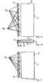
- eine Anordnung einer Vielzahl von Leuchtmitteln auf einem Leucht- mittelträger zur Einstrahlung in einen Lichtleitkörper, wobei die Leuchtmittel verschiedenartige Lichtfunktionen aufweisen können,
- Fig. 1b
- eine Seitenansicht der Anordnung aus
Figur 1a , - Fig. 2
- eine schematische Ansicht einer Vielzahl von Leuchtmitteln auf einem Leuchtmittelträger, wobei die Leuchtmittel als Multimedia-Leuchtdioden ausgeführt sind,
- Fig. 3
- eine schematische Ansicht der Anordnung einer Vielzahl von Leucht- mitteln, wobei die Leuchtmittel zur Einstrahlung in einen Lichtleitkörper bereichsweise voneinander getrennt auf dem Leuchtmittelträger angeordnet sind,
- Fig. 4a
- eine schematische Ansicht einer Vielzahl von Leuchtmitteln auf einem Leuchtmittelträger zur Einstrahlung in einen Lichtleitkörper, wobei Leuchtmittel verschiedener Farbe unterschiedlich auf dem Leuchtmittelträger angeordnet sind,
- Fig. 4b
- eine schematische Seitenansicht der Anordnung gemäß
Figur 4a , - Fig. 4c-4f
- verschiedene Ausführungsbeispiele der Anordnung von Leuchtmitteln verschiedenartiger Lichtfunktionen, wobei die Anordnung der Leucht- mittel zueinander variiert,
- Fig. 5a
- eine schematische Ansicht der Ansteuerung von Leuchtmitteln verschiedenartiger Lichtfunktionen durch eine gemeinsame elektronische Ansteuereinheit und
- Fig. 5b
- eine Ansicht zur Ansteuerung einer Vielzahl von Leuchtmitteln unterschiedlicher Lichtfunktion mit einem zusätzlichen Bauelement.
Figur 1aVielzahl von Leuchtmitteln 1a und 1b.Die Leuchtmittel 1a und 1b besitzen verschiedenartige Lichtfunktionen, die über unterschiedliche Lichtfarben, Leuchtstärke oder Betriebsart bereitgestellt werden. Leuchtdioden einer ersten Lichtfunktion sindmit 1a gekennzeichnet, wobei Leuchtmittel mit einer zweitenLichtfunktion mit 1b gekennzeichnet sind. Gemäß dem dargestellten Ausführungsbeispiel sind dieLeuchtmittel 1a und 1b wechselweise benachbart zueinander auf dem Leuchtmittelträger angeordnet. Beispielsweise kann eine erste Lichtfarbe weißes Licht betreffen, wobei eine zweite Lichtfarbe gelbes Licht aufweist. Wird die Funktion Positionslicht und/oder Tagfahrlicht benötigt, so können die ersten Leuchtmittel 1a mit weißer Lichtfarbe betrieben werden. Wird eine Blinklichtfunktion zur Fahrtrichtungsanzeige gefordert, können die zweiten Leuchtmittel 1b mit einer gelben Farbe eingeschaltet werden, wobei die Betriebsart ein Blinklicht umfassen kann. Durch denBetrieb der Leuchtmittel 1a und 1b wird Licht indie Lichtleitkörper 2 angekoppelt und über dieAustrittsfläche 3 bereitgestellt.Die Lichtaustrittsfläche 3 kann unterhalb der Licht- oder Streuscheibe der Beleuchtungseinrichtung angeordnet sein, wobei die Beleuchtungseinrichtung einen Frontscheinwerfer eines Kraftfahrzeugs darstellt. Dabeidefiniert die Lichtaustrittsfläche 3 einen Lichtfunktionsbereich innerhalb des Scheinwerfers, über den erfindungsgemäß sowohl Blinklicht als auch ein Positionslicht und/oder ein Tagfahrlicht bereitgestellt wird.Figur 1bdem Leuchtmittelträger 4. Dieser ist vor einem Lichtleitkörper 2 angeordnet, so dassdas von Leuchtmitteln 1a und1b emittierte Licht indie Lichtleitkörper 2 einkoppeln kann. Dieser kann sowohl eine stirnseitige Lichtaustrittsfläche 3 besitzen, wobei auch die Seitenflächen desLichtleitkörpers 2Lichtaustrittsflächen 3 bilden können.Der Lichtleitkörper 2 ist dabei nicht auf einen rechteckigen Querschnitt gemäß der Darstellung begrenzt.Figur 2einen Lichtleitkörper 2 und zur Bereitstellung des eingestrahlten Lichtes über eine Lichtaustrittsfläche 3. Gemäß diesem Ausführungsbeispiel sind die Leuchtmittel als Leuchtdioden (LEDs) ausgebildet, die wechselweise Licht in verschiedener Farbe aussenden können. Folglich ist nicht die Anordnung erster und zweiter Leuchtmittel aufden Leuchtmittelträger 4 erforderlich, so dass die Leuchtmittel 1c jeweils entweder weißes Licht für das Tagfahrlicht und/oder das Positionslicht oder gelbes Licht zur Bereitstellung eines Blinklichtes zur Fahrtrichtungsanzeige emittieren können.Figur 3Anordnung von Leuchtmitteln 1a auf einem Leuchtmittelträger 4, wobei sämtliche aufdem Leuchtmittelträger 4aufgenommenen Leuchtmittel 1a zur Aussendung einer gleichen Farbe ausgebildet sind.Die Leuchtmittel 1a können weißes Licht emittieren, so dass zunächst inden Lichtleitkörper 2 lediglich weißes Licht eingekoppelt wird. Gemäß diesem Ausführungsbeispielist der Lichtleitkörper 2 in zwei Bereiche unterteilt, wobei die Unterteilung der beiden Bereiche durch eine lichtundurchlässige Trennebene 7 erfolgt. Der oberhalb derTrennebene 7 angeordnete Bereich desLichtleitkörpers 2 kann transparent sein, so dass über dieLichtaustrittsfläche 3 weißes Licht emittiert wird. Der unterhalb derTrennebene 7 angeordnete Bereich desLichtleitkörpers 2 kann beispielsweise gelb eingefärbt sein, so dass trotz des eingekoppelten Lichtes weißer Farbe über dieLichtaustrittsfläche 3 eine gelbe Farbe zur Bereitstellung eines Blinklichtes emittiert wird. Durch dieLichtundurchlässigkeit der Trennebene 7 kann sich das emittierte weiße und das emittierte gelbe Licht nicht miteinander mischen.- In
Figur 4 a ist zunächst die Anordnung verschiedener Leuchtmittel 1a,b,c auf einem Leuchtmittelträger 4 dargestellt. Diese können Licht verschiedener Lichtfunktionen bereitstellen und inden Lichtleitkörper 2 einkoppeln, um die jeweilige Lichtfunktion über dieLichtaustrittsfläche 3 bereitzustellen. Femer ist inFigur 4a eine Querschnittsebene angedeutet, wobei der zugeordnete Querschnitt inFigur 4b gezeigt ist. Figur 4b zeigt die Ansicht eines Querschnittes durchden Leuchtmittelträger 4sowie den Lichtleitkörper 2. Es ist angedeutet, dass dieLeuchtmittel 1a und 1b in zwei übereinander liegenden Reihen aufdem Leuchtmittelträger 4 angeordnet sind. Gemäß der Darstellung besitzt der Lichtleitkörper 2 eine trapezartige Querschnittsform,wobei die Lichtaustrittsflächen 3 sowohl stirnseitig als auch ober- und unterseitig vorhanden sind.Der Lichtleitkörper 2 kann sich 3-dimensional in einen Raum hinein erstrecken, um beispielsweise der räumlichen Kontur eines Scheinwerfers zu folgen. Femer kann der Lichtleitkörper 2 Teil der Lichtscheibe des Scheinwerfers sein, so dass die Form einer "Dickwandoptik" entsteht. In den folgendenFiguren 4c-4f sind verschiedene Anordnungen der Leuchtmittel 1a und 1b mit jeweils zugeordneten Lichtfunktionen dargestellt.- In den
Figuren 4c-f ist eine jeweilige Draufsicht auf einen Leuchtmittelträger 4 gezeigt. InFigur 4c sind in einer oberen Reihe erste Leuchtmittel 1a und in einer unteren Reihe zweite Leuchtmittel 1b aufdem Leuchtmittelträger 4 angeordnet.Die ersten Leuchtmittel 1a können weißes Licht emittieren, wohingegen diezweiten Leuchtmittel 1b gelbes Licht aussenden.Die 1b können unabhängig voneinander betrieben werden, so dass beispielsweise unabhängig von einem eingeschalteten Positions- oder Tagfahrlicht eine Blinkfunktion zur Fahrtrichtungsanzeige erfüllt werden kann.Leuchtmittel 1a und Figur 4d zeigt ein weiteres Ausführungsbeispiel zur Anordnung erster und zweiter Leuchtmittel 1a und 1b, wobei in einer übereinander liegenden Ordnung erste Leuchtmittel 1a abwechselnd zu zweiten Leuchtmitteln 1b aufdem Leuchtmittelträger 4 aufgebracht sind.- In
Figur 4e ist die Anordnung der Leuchtmittel übereinander abwechselnd vorgenommen, so dassein Leuchtmittel 1a inQuerrichtung des Leuchtmittelträgers 4mit einem Leuchtmittel 1b abwechselnd angeordnet ist. - In
Figur 4f ist eine weitere möglicheAnordnung von 1b auf einem Leuchtmittelträger 4 dargestellt. Die ersten und zweiten LeuchtmittelLeuchtmitteln 1a und1a und 1b sind derart ausgeführt, dass dieLeuchtmittel 1a ein W ergeben, wobei zwischen den erstenLeuchtmitteln 1a diezweiten Leuchtmittel 1b abwechselnd angeordnet sind. - Die
Figuren 5a und 5b zeigen ein Ausführungsbeispiel zur Ansteuerung der Leuchtmittel1a und 1b durch eine elektronische Ansteuereinheit 5.Die elektronische Ansteuereinheit 5 wird über Signalleitungen 8 von der Fahrzeugelektronik angesteuert. Gemäß der Darstellung ist erkennbar, dass sowohldie ersten Leuchtmittel 1a zur Erfüllung einer ersten Lichtfunktion und diezweiten Leuchtmittel 1b zur Erfüllung einer zweiten Lichtfunktion gemeinsam durch eine elektronische Ansteuereinheit 5 angesteuert werden. Dies kann realisiert werden, wenn zum Beispiel Funktionen mit ähnlichen oder gleichen elektronischen Erfordernissen im Wechsel zueinander eingeschaltet werden müssen.Die elektronische Ansteuereinheit 5 versorgt folglich entweder die eine oder die andere Funktion durch Bestromung entweder der ersten Leuchtmittel 1a oder der zweiten Leuchtmittel 1b.
- Fig. 1a
- an arrangement of a multiplicity of lamps on a lamp carrier for irradiation into a light guide body, the lamps being able to have different light functions,
- Fig. 1b
- a side view of the arrangement
Figure 1a , - Fig. 2
- 1 shows a schematic view of a multiplicity of lamps on a lamp carrier, the lamps being designed as multimedia light-emitting diodes,
- Fig. 3
- 2 shows a schematic view of the arrangement of a multiplicity of light sources, the light sources for irradiation into a light-guiding body being arranged in regions separated from one another on the light source carrier,
- Fig. 4a
- 1 shows a schematic view of a multiplicity of lamps on a lamp carrier for irradiation into a light guide body, lamps of different colors being arranged differently on the lamp carrier,
- Fig. 4b
- is a schematic side view of the arrangement
Figure 4a , - 4c-4f
- different exemplary embodiments of the arrangement of illuminants of different types of light functions, the arrangement of the illuminants varying with respect to one another,
- Fig. 5a
- a schematic view of the control of illuminants of various types of light functions by a common electronic control unit and
- Fig. 5b
- a view for controlling a variety of lamps with different light function with an additional component.
Figure 1a shows a schematic representation of a first embodiment of the arrangement of a plurality oflamps lamps lamps first lamps 1a can be operated with a white light color. If a flashing light function is required to indicate the direction of travel, thesecond lamps 1b can be switched on with a yellow color, and the operating mode can include a flashing light. Through the operation of theilluminants light guide body 2 and made available via theexit surface 3. Thelight exit surface 3 can be arranged below the light or diffusing screen of the lighting device, the lighting device representing a headlight of a motor vehicle. In this case, thelight exit surface 3 defines a light function area within the headlight, via which, according to the invention, both the blinking light and a position light and / or a daytime running light are provided.Figure 1b shows a side view of the arrangement of thelamps lamp holder 4. This is arranged in front of alight guide body 2, so that the light emitted bylamps light guide body 2. This can both have alight exit surface 3 on the end face, and the side surfaces of thelight guide body 2 can also form light exit surfaces 3. Thelight guide body 2 is not limited to a rectangular cross section as shown.Figure 2 shows a further embodiment of the arrangement of lamps 1c on alamp carrier 4 for irradiation into alight guide body 2 and for providing the incident light via alight exit surface 3. According to this embodiment, the lamps are designed as light emitting diodes (LEDs) which alternately emit light in different colors can. Consequently, the arrangement of first and second illuminants on theilluminant carrier 4 is not necessary, so that the illuminants 1c can each emit either white light for the daytime running light and / or the position light or yellow light for providing a flashing light for indicating the direction of travel.Figure 3 shows a further embodiment of the arrangement oflamps 1a on alamp carrier 4, wherein alllamps 1a received on thelamp carrier 4 are designed to emit the same color. Theilluminants 1 a can emit white light, so that initially only white light is coupled into thelight guide body 2. According to this exemplary embodiment, thelight guide body 2 is divided into two areas, the two areas being divided by anopaque parting plane 7. The region of thelight guide body 2 arranged above theparting plane 7 can be transparent, so that white light is emitted via thelight exit surface 3. The area of thelight guide body 2 arranged below theparting plane 7 can, for example, be colored yellow, so that despite the light that is coupled in, white color is emitted via thelight exit surface 3 to provide a flashing light. Due to the opacity of theparting plane 7, the emitted white and the emitted yellow light cannot mix with one another.- In
Figure 4 a, the arrangement ofdifferent lamps 1a, b, c on alamp carrier 4 is initially shown. These can provide light of different light functions and couple them into thelight guide body 2 in order to provide the respective light function via thelight exit surface 3. It is also inFigure 4a a cross-sectional plane indicated, with the assigned cross-section inFigure 4b is shown. Figure 4b shows the view of a cross section through theilluminant carrier 4 and thelight guide body 2. It is indicated that theilluminants illuminant carrier 4. According to the illustration, thelight guide body 2 has a trapezoidal cross-sectional shape, the light exit surfaces 3 being present both on the end face and on the top and bottom sides. Thelight guide body 2 can extend 3-dimensionally into a room, for example in order to follow the spatial contour of a headlight. Furthermore, thelight guide body 2 can be part of the lens of the headlight, so that the shape of a "thick-wall optic" is created. In the followingFigures 4c-4f Different arrangements of theilluminants - In the
Figures 4c-f A respective top view of alamp carrier 4 is shown. InFigure 4c areFirst lamps 1a are arranged in an upper row andsecond lamps 1b in a lower row on thelamp holder 4. Thefirst illuminants 1a can emit white light, whereas thesecond illuminants 1b emit yellow light. Thelamps Figure 4d shows a further exemplary embodiment for the arrangement of first andsecond lamps first lamps 1 a being arranged in an overlapping order alternating withsecond lamps 1 b on thelamp carrier 4.- In
Figure 4e the arrangement of the lamps is made alternately one above the other, so that alamp 1a is alternately arranged in the transverse direction of thelamp carrier 4 with alamp 1b. - In
Figure 4f Another possible arrangement oflamps lamp carrier 4 is shown. The first andsecond illuminants illuminants 1a result in a W, thesecond illuminants 1b being arranged alternately between thefirst illuminants 1a. - The
Figures 5a and 5b show an embodiment for controlling thelamps electronic control unit 5. Theelectronic control unit 5 is controlled viasignal lines 8 by the vehicle electronics. According to the illustration, it can be seen that both thefirst lamps 1 a to fulfill a first light function and thesecond lamps 1 b to fulfill a second light function are controlled together by anelectronic control unit 5. This can be realized if, for example, functions with similar or identical electronic requirements have to be switched on alternately. Theelectronic control unit 5 consequently supplies either one or the other function by energizing either thefirst illuminant 1a or thesecond illuminant 1b.
Um diese Funktion zu erfüllen, kann ein Umschalter vorgesehen sein, der innerhalb der elektronischen Ansteuereinheit 5 integriert ist. Konkret kann durch die vorgeschlagene Ansteuerung die Funktion eines Tagfahrlichtes mit der Funktion einer Blinkleuchte kombiniert werden. Sollten die elektronischen Eigenschaften der beiden Funktionen zu stark voneinander abweichen, kann durch ein zusätzliches Bauelement 6, das beispielhaft einer Gruppe der Leuchtmitteln 1b zugeordnet ist, eine Angleichung erfolgen.In order to fulfill this function, a changeover switch can be provided, which is integrated within the
Die Erfindung beschränkt sich in ihrer Ausführung nicht auf das vorstehend angegebene bevorzugte Ausführungsbeispiel. Vielmehr ist eine Anzahl von Varianten denkbar, welche von der dargestellten Lösung auch bei grundsätzlich anders gearteten Ausführungen Gebrauch macht. Sämtliche aus den Ansprüchen, der Beschreibung oder den Zeichnungen hervorgehenden Merkmale und/oder Vorteile, einschließlich konstruktiven Einzelheiten, räumliche Anordnungen und Verfahrensschritte, können sowohl für sich als auch in den verschiedensten Kombinationen erfindungswesentlich sein. Im Ergebnis wird im Rahmen der vorliegenden Erfindung eine Lichtaustrittsfläche 3 als Funktionsbereich einer Leuchte für ein Kraftfahrzeug vorgeschlagen, die eine hohe Integrationsdichte bei einer Vielzahl von Funktionen ermöglicht.The embodiment of the invention is not limited to the preferred exemplary embodiment specified above. Rather, a number of variants are conceivable which make use of the solution shown, even in the case of fundamentally different types. All of the features and / or advantages arising from the claims, the description or the drawings, including structural details, spatial arrangements and method steps, can be essential to the invention both individually and in the most varied of combinations. As a result, in the context of the present invention, a
- 1a, 1b1a, 1b
- Leuchtmittel, LEDIlluminant, LED
- 22nd
- LichtleitkörperLight guide body
- 33rd
- LichtaustrittsflächeLight exit surface
- 44th
- LeuchtmittelträgerBulb holder
- 55
- elektronische Ansteuereinheitelectronic control unit
- 66
- zusätzliches Bauelementadditional component
- 77
- lichtundurchlässige Trennebeneopaque parting plane
- 88th
- SignalleitungSignal line
Claims (13)
- Illumination device for a motor vehicle with a plurality of light sources (1a, 1b, 1c) that are designed as headlamps of the motor vehicle where various light functions in the illumination device are allocated to the light sources (1a, 1b, 1c),characterized in that at least one light guide element (2) is provided for and the light sources (1a, 1b, 1c), operating together,
incouple into the light guide element (2) light of various kinds of light function and where the light guide element (2) features at least one light exit area (3) in order to make the various kinds of light functions available through the light exit area (3) andin that the light sources (1a, 1b, 1c) of various kinds of light functions are arranged together on a light source carrier (4), where one first light function takes the form of a daytime running light and of a position light and a second light function takes the form of a direction indicator light to indicate the direction of travel and where LEDs emitting white light (1a) and LEDs emitting amber light LEDs (1b) are mounted on the light source carrier (4) alternately to each other. - Illumination device in accordance with Claim 1,characterized in that the light sources (1a, 1b, 1c) of various kinds of light function are designed to emit light colors distinct from each other.
- Illumination device in accordance with Claim 2,characterized in that first light sources (1a) of a first light color are, in some areas, arranged on the light source carrier (4) separately from second light sources (1b) of a second light color.
- Illumination device in accordance with Claim 1 or 2,characterized in that first light sources (1a) of a first light color with second light sources (1b) of a second light color are arranged on the light source carrier (4) alternately adjacent to each other.
- Illumination device in accordance with one of the aforementioned Claims,characterized in that the light sources (1a, 1b, 1c) are designed as LEDs (light emitting diodes) (1a, 1b) that are mounted on the light source carrier (4).
- Illumination device in accordance with one of the aforementioned Claims,characterized in that LEDs (1a, 1b, 1c) are each designed to alternately emit light of a different color.
- Illumination device in accordance with one of the aforementioned Claims,characterized in that the light guide element (2) features a first area into which the LEDs emitting white light (1a) shine and where the light guide element (2) features a second area into which the LEDs emitting amber light (1b) shine.
- Illumination device in accordance with one of the aforementioned Claimscharacterized in that the first area of the light guide element (2) and the second area of the light guide element (2) feature different kinds of material and/or color components.
- Illumination device in accordance with one of the aforementioned claimscharacterized in that the light guide element (2) features a longitudinal extension, where LEDs (1a, 1b, 1c) with various kinds of light function are arranged in the direction of the extension or at a right angle to the direction of the extension of the light guide element (2) for shining into the light guide element (2).
- Illumination device in accordance with one of the aforementioned Claims,characterized in that an electronic actuator unit (5) is provided for, where the light sources (1a, 1b, 1c) with various kinds of light function can be actuated together by the electronic actuator unit (5).
- Illumination device in accordance with Claim 10,characterized in that the light sources (1a, 1b, 1c) with various kinds of light function can be alternately operated by an electronic actuator device (5) so that the electronic actuator unit (5) actuates either LEDs (1a) with a first light function or LEDs (1b) with a second light function.
- Illumination device in accordance with Claim 10 or 11,characterized in that the electronic actuator unit (5) features a change-over switch in order to facilitate actuation of the light sources (1a, 1b, 1c) of various kinds of light function.
- Illumination device in accordance with Claims 10 through 12,characterized in that the electronic actuator device (5) features at least one additional component part (6) in the event of light functions of the actuated light sources (1a, 1b, 1c) that differ significantly from each other.
Priority Applications (2)
| Application Number | Priority Date | Filing Date | Title |
|---|---|---|---|
| AT08163803TATE533007T1 (en) | 2008-09-05 | 2008-09-05 | LIGHTING DEVICE FOR A MOTOR VEHICLE |
| EP08163803.3AEP2161494B2 (en) | 2008-09-05 | 2008-09-05 | Lighting device for a motor vehicle |
Applications Claiming Priority (1)
| Application Number | Priority Date | Filing Date | Title |
|---|---|---|---|
| EP08163803.3AEP2161494B2 (en) | 2008-09-05 | 2008-09-05 | Lighting device for a motor vehicle |
Publications (3)
| Publication Number | Publication Date |
|---|---|
| EP2161494A1 EP2161494A1 (en) | 2010-03-10 |
| EP2161494B1 EP2161494B1 (en) | 2011-11-09 |
| EP2161494B2true EP2161494B2 (en) | 2020-04-29 |
Family
ID=39884194
Family Applications (1)
| Application Number | Title | Priority Date | Filing Date |
|---|---|---|---|
| EP08163803.3AActiveEP2161494B2 (en) | 2008-09-05 | 2008-09-05 | Lighting device for a motor vehicle |
Country Status (2)
| Country | Link |
|---|---|
| EP (1) | EP2161494B2 (en) |
| AT (1) | ATE533007T1 (en) |
Cited By (2)
| Publication number | Priority date | Publication date | Assignee | Title |
|---|---|---|---|---|
| US12038148B1 (en) | 2023-09-13 | 2024-07-16 | Valeo Vision | Reconfigurable light that provides multiple different light configurations from a single housing and controlling the reconfigurable light |
| US12078315B1 (en) | 2023-09-13 | 2024-09-03 | Valeo Vision | Reconfigurable light that provides multiple different light configurations from a single housing and controlling the reconfigurable light |
Families Citing this family (71)
| Publication number | Priority date | Publication date | Assignee | Title |
|---|---|---|---|---|
| FR2947325B1 (en) | 2009-06-30 | 2013-08-16 | Valeo Vision | OPTICAL DEVICE, IN PARTICULAR FOR MOTOR VEHICLE |
| EP2390136A1 (en)* | 2010-05-31 | 2011-11-30 | Fico Mirrors, S.A. | Assembly having a housing comprising a circuit board supporting a plurality of light emitting diodes |
| DE102010056313C5 (en)* | 2010-12-27 | 2017-03-16 | Automotive Lighting Reutlingen Gmbh | Lighting device of a motor vehicle |
| DE102011018573A1 (en) | 2011-04-26 | 2012-10-31 | Audi Ag | Drive device for a lighting device of a motor vehicle and motor vehicle |
| AT511499A1 (en)* | 2011-05-30 | 2012-12-15 | Zizala Lichtsysteme Gmbh | VEHICLE HEADLAMP WITH LED LIGHT MODULES FOR GENERATING A MAIN LIGHT DISTRIBUTION AND AN ADDITIONAL LIGHT DISTRIBUTION |
| US9081125B2 (en) | 2011-08-08 | 2015-07-14 | Quarkstar Llc | Illumination devices including multiple light emitting elements |
| DE102012102301B4 (en)* | 2012-03-19 | 2021-06-17 | OSRAM Opto Semiconductors Gesellschaft mit beschränkter Haftung | Optoelectronic semiconductor chip and headlight with such a semiconductor chip |
| DE102012017596A1 (en)* | 2012-09-06 | 2014-03-06 | Volkswagen Aktiengesellschaft | Light equipment for vehicle, has multiple separate light sources, where multiple separate light conductors are so assigned to light sources that light emitted in different colors are coupled into light conductors |
| DE102012111313B4 (en) | 2012-11-23 | 2023-09-28 | HELLA GmbH & Co. KGaA | Lighting unit for a motor vehicle |
| DE102012112076A1 (en) | 2012-12-11 | 2014-06-12 | Hella Kgaa Hueck & Co. | Lighting device for vehicles, has multiple light sources for generating different light functions and light conducting body comprising light conducting segment with deflection surface, at which light beam is totally reflectable |
| US9733414B2 (en) | 2013-02-08 | 2017-08-15 | Quarkstar Llc | Illumination system based on active and passive illumination devices |
| FR3002895B1 (en)* | 2013-03-05 | 2016-12-23 | Peugeot Citroen Automobiles Sa | DIRECTION CHANGE INDICATION DEVICE OF A VEHICLE WITH A LIGHT GUIDE AND OPALIN SCREEN |
| FR3005495B1 (en)* | 2013-05-13 | 2018-01-05 | Valeo Vision | BI-COLOR LIGHTING AND / OR SIGNALING DEVICE, IN PARTICULAR FOR A MOTOR VEHICLE. |
| EP3422059B1 (en) | 2013-07-18 | 2025-09-03 | Quarkstar LLC | Illumination device in which source light injection is non-parallel to device's optical axis |
| CN105723150B (en) | 2013-09-17 | 2019-02-22 | 夸克星有限责任公司 | Light guide lighting fixture with light divergence modifier |
| WO2015081974A1 (en)* | 2013-12-02 | 2015-06-11 | Osram Opto Semiconductors Gmbh | Led module and lighting system |
| FR3016428B1 (en)* | 2014-01-15 | 2020-08-28 | Valeo Illuminacion | LIGHT GUIDANCE DEVICE FOR LIGHTING AND / OR SIGNALING DEVICE, LIGHTING AND / OR SIGNALING DEVICE INCLUDING LEDIT DEVICE AND OPTICAL BLOCK FOR MOTOR VEHICLE |
| FR3019117B1 (en) | 2014-04-01 | 2017-12-22 | Valeo Vision | LUMINOUS MODULE, IN PARTICULAR LIGHTING AND / OR SIGNALING OF A MOTOR VEHICLE |
| US9242581B2 (en) | 2014-06-25 | 2016-01-26 | Ford Global Technologies, Llc | Automatic presentable swiveling seat |
| DE102014110225A1 (en)* | 2014-07-21 | 2016-01-21 | Osram Opto Semiconductors Gmbh | vehicle light |
| US9393899B2 (en) | 2014-07-28 | 2016-07-19 | Valeo North America, Inc. | System and method for controlling a lighting and/or signaling device |
| FR3027856A1 (en)* | 2014-11-03 | 2016-05-06 | Valeo Vision | LUMINOUS MODULE FOR A MOTOR VEHICLE COMPRISING A LIGHT GUIDE |
| EP3215790B1 (en) | 2014-11-07 | 2020-01-08 | Quarkstar LLC | Stack lighter luminaire |
| US9348080B1 (en) | 2014-11-18 | 2016-05-24 | Quarkstar Llc | Wall wash luminaire with light guide and optical element therefore |
| CN104456373B (en)* | 2014-12-24 | 2016-09-14 | 东莞市闻誉实业有限公司 | Radix Saposhnikoviae LED street lamp |
| DE102015204747B4 (en) | 2015-03-17 | 2025-03-13 | Volkswagen Aktiengesellschaft | Lighting device for a motor vehicle |
| CZ2015588A3 (en) | 2015-08-31 | 2017-03-08 | Varroc Lighting Systems S.R.O. | A lighting device, particularly a signalling lamp for motor vehicles |
| FR3041414A1 (en)* | 2015-09-22 | 2017-03-24 | Valeo Vision | OPTICAL MODULE FOR A MULTIFUNCTIONAL MOTOR VEHICLE PROJECTOR, COMPRISING A LIGHT GUIDE INCORPORATING REFLECTORS |
| DE202015105115U1 (en)* | 2015-09-28 | 2016-12-30 | SMR Patents S.à.r.l. | Lighting unit and rearview mirror for vehicles |
| FR3046656B1 (en)* | 2016-01-11 | 2019-11-29 | Valeo Iluminacion | LUMINOUS MODULE FOR A MOTOR VEHICLE COMPRISING TWO TYPES OF LIGHT SOURCES |
| CN109328281A (en)* | 2016-04-25 | 2019-02-12 | 夸克星有限责任公司 | Multiple beam car light |
| WO2018006507A1 (en)* | 2016-07-06 | 2018-01-11 | 上海小糸车灯有限公司 | Vehicle lamp illumination device with different functions |
| CN106016127A (en)* | 2016-07-06 | 2016-10-12 | 上海小糸车灯有限公司 | Car lamp lighting device with different functions |
| JP6720809B2 (en) | 2016-09-29 | 2020-07-08 | オムロン株式会社 | Light guide member, light guide member unit, and lighting device |
| CN108613099B (en)* | 2016-12-16 | 2024-02-23 | 市光法雷奥(佛山)汽车照明系统有限公司 | Multifunctional lighting device for motor vehicle |
| FR3063335B1 (en)* | 2017-02-28 | 2021-07-02 | Valeo Vision | LIGHTING DEVICE FOR MOTOR VEHICLES INCLUDING A LIGHT SOURCE CONTAINING A PLURALITY OF EMISSIONS |
| CN108916806A (en)* | 2017-04-21 | 2018-11-30 | 上海小糸车灯有限公司 | Using the vehicle light illumination device of block form light guide |
| DE102017115899B4 (en) | 2017-07-14 | 2023-11-02 | Automotive Lighting Reutlingen Gmbh | Motor vehicle light and motor vehicle headlight with such a light |
| DE102017213733A1 (en)* | 2017-08-08 | 2019-02-14 | Osram Gmbh | Luminaire with two light sources and an optic |
| EP3505818B1 (en)* | 2017-11-16 | 2023-01-04 | Stanley Electric Co., Ltd. | Vehicular lamp and lighting control circuit of vehicular lamp |
| DE102018203598A1 (en)* | 2018-03-09 | 2019-09-12 | BSH Hausgeräte GmbH | Household appliance with a display device |
| DE102018004013A1 (en)* | 2018-05-18 | 2018-10-31 | Daimler Ag | vehicle light |
| WO2020006570A1 (en) | 2018-06-29 | 2020-01-02 | Matthew Coburn | Exterior light and charge indicator |
| FR3085637A1 (en)* | 2018-09-07 | 2020-03-13 | Psa Automobiles Sa | MULTIPLE WALL PHOTON REFLECTING PIECE LIGHTING DEVICE FOR DIFFERENT PHOTOMETRIC FUNCTIONS |
| FR3086368B1 (en)* | 2018-09-25 | 2021-04-16 | Psa Automobiles Sa | LIGHT GUIDE LIGHTING DEVICE WITH VARIABLE LIGHTING LENGTH ACCORDING TO NEEDS |
| FR3087519B1 (en) | 2018-10-17 | 2022-05-06 | Psa Automobiles Sa | BI-FUNCTION LIGHT MODULE FOR OPTICAL VEHICLE LIGHTING AND/OR SIGNALING UNIT |
| US10704757B2 (en) | 2018-10-19 | 2020-07-07 | Valeo North America, Inc. | Lighting unit for automotive headlamp |
| FR3087520B1 (en) | 2018-10-19 | 2021-04-09 | Psa Automobiles Sa | LIGHT MODULE ENSURING TWO PHOTOMETRIC FUNCTIONS PRESENTING SEPARATE LIGHT SIGNATURES |
| KR102682009B1 (en) | 2018-11-13 | 2024-07-08 | 삼성전자주식회사 | Light emitting module and light apparatus for car including the same |
| EP3894741B1 (en) | 2018-12-13 | 2023-02-15 | Lumileds LLC | Automotive headlight with dual correlated colour temperature |
| US11867370B2 (en) | 2019-02-13 | 2024-01-09 | Lumileds Llc | Lighting device for multiple automotive lighting functions |
| EP3705776A1 (en)* | 2019-03-08 | 2020-09-09 | Lumileds Holding B.V. | Lighting device for multiple automotive lighting functions |
| US10578271B1 (en) | 2019-04-17 | 2020-03-03 | Excellence Optoelectronics Inc. | Vehicle LED linear lighting module |
| FR3097935B1 (en)* | 2019-06-25 | 2021-12-10 | Valeo Vision | Lighting and / or signaling device |
| GB2585687B (en) | 2019-07-11 | 2021-08-18 | Dyson Technology Ltd | Vehicle lamps |
| CN112443814B (en) | 2019-08-28 | 2024-08-30 | 法雷奥照明湖北技术中心有限公司 | Light guide assembly, vehicle lamp and vehicle |
| FR3104236B1 (en)* | 2019-12-10 | 2022-01-14 | Psa Automobiles Sa | LIGHT GUIDE LIGHTING DEVICE SUBDIVIDED INTO PARTS BY AT LEAST ONE INTERNAL REFLECTIVE ELEMENT |
| FR3105360B1 (en) | 2019-12-20 | 2022-07-22 | Valeo Iluminacion Sa | Light module of a motor vehicle comprising two light sources |
| DE102020108010A1 (en)* | 2020-03-24 | 2021-09-30 | Bayerische Motoren Werke Aktiengesellschaft | Lighting device for a motor vehicle |
| ES2869550A1 (en)* | 2020-04-23 | 2021-10-25 | Seat Sa | LIGHTING DEVICE AND HEADLIGHT FOR A VEHICLE INCLUDING THE LIGHTING DEVICE |
| KR102849288B1 (en) | 2020-06-01 | 2025-08-22 | 삼성전자주식회사 | Flash led package |
| DE102021100197B4 (en) | 2021-01-08 | 2025-07-24 | HELLA GmbH & Co. KGaA | Projection module for vehicles with two main light primary optics, two signal light primary optics and a common secondary optic |
| CN113028355B (en)* | 2021-03-23 | 2022-01-07 | 华域视觉科技(上海)有限公司 | Car light optical assembly, illumination optical device and vehicle |
| FR3122131A1 (en) | 2021-04-26 | 2022-10-28 | Psa Automobiles Sa | Illumination module for optical unit for lighting and/or motor vehicle signaling |
| US11945366B2 (en) | 2022-06-24 | 2024-04-02 | Rivian Ip Holdings, Llc | Delivery lighting |
| US12018810B2 (en) | 2022-07-08 | 2024-06-25 | Rivian Ip Holdings, Llc | Crossbar with lighting |
| CN117628431A (en)* | 2022-08-12 | 2024-03-01 | 巨铠精密工业股份有限公司 | Multi-light source lighting module and its automotive lamps |
| US12326233B2 (en) | 2022-12-29 | 2025-06-10 | Rivian Ip Holdings, Llc | Light apparatus |
| US12338972B2 (en) | 2023-06-21 | 2025-06-24 | Rivian Ip Holdings, Llc | Heated lens |
| TWI848785B (en)* | 2023-08-02 | 2024-07-11 | 巨鎧精密工業股份有限公司 | Integrated two-color headlight device |
| US12434623B2 (en) | 2024-02-14 | 2025-10-07 | Rivian Ip Holdings, Llc | Apparatus with light fixture |
Citations (5)
| Publication number | Priority date | Publication date | Assignee | Title |
|---|---|---|---|---|
| DE19838224A1 (en)† | 1998-08-22 | 2000-02-24 | Daimler Chrysler Ag | Front lamp arrangement for cars has additional lamp devices with optic fibre element conducting light from entry side to exit side around periphery of headlamp unit |
| JP2006236588A (en)† | 2005-02-22 | 2006-09-07 | Koito Mfg Co Ltd | Optical llumination device and vehicular lighting fixture |
| DE102005043992A1 (en)† | 2005-09-14 | 2007-05-10 | Automotive Lighting Reutlingen Gmbh | Signal light for vehicles |
| DE102006027970A1 (en)† | 2005-10-19 | 2007-10-04 | Volkswagen Ag | Headlight unit for vehicle, has low- or high-beam is adjustable in its brightness and tube emitting light is coaxially enclosed by transparent hollow body as light emitter |
| DE102007005779A1 (en)† | 2007-02-06 | 2008-08-07 | Automotive Lighting Reutlingen Gmbh | Lighting device for use in vehicle i.e. motor vehicle, has optical element arranged outside light conductor and to deflect light uncoupled from light conductor from uncoupling direction into direction deviated from uncoupling direction |
Family Cites Families (10)
| Publication number | Priority date | Publication date | Assignee | Title |
|---|---|---|---|---|
| DE3916875A1 (en)* | 1989-05-24 | 1990-12-06 | Ullmann Ulo Werk | Signal light esp. multi-compartment signal lights for motor vehicle - uses green, red, and blue LED's combined so that single light is given with help of mix optics |
| DE19753096A1 (en) | 1997-11-29 | 1999-06-02 | Volkswagen Ag | Motor vehicle light |
| DE10043660A1 (en) | 2000-09-05 | 2002-03-14 | Volkswagen Ag | Motor vehicle light has two LED matrices of different colors in common light body to form overall matrix; matrices are separately and independently controlled, distributed in same manner |
| DE10052655B4 (en)* | 2000-10-24 | 2010-04-08 | Volkswagen Ag | Lighting device for motor vehicles |
| DE20018905U1 (en)* | 2000-11-06 | 2001-03-01 | Lite On Electronics Inc | Luminescent diodes (LED) - vehicle signal light |
| JP2004001710A (en) | 2002-04-11 | 2004-01-08 | Iisamu:Kk | Side mirror cover, side mirror body and lamp used for these |
| US6880960B2 (en) | 2003-03-26 | 2005-04-19 | E'sam Co., Ltd. | Side mirror cover and side mirror body |
| DE102005032921B4 (en)* | 2005-07-14 | 2007-03-08 | Daimlerchrysler Ag | Lighting device for a vehicle |
| DE102005042611A1 (en)* | 2005-09-07 | 2007-03-22 | Volkswagen Ag | Lighting device for a vehicle with two groups of light sources for at least two light functions |
| DE102005048498B4 (en)* | 2005-10-07 | 2007-06-21 | Schefenacker Vision Systems Germany Gmbh | Multicolored vehicle exterior light |
- 2008
- 2008-09-05EPEP08163803.3Apatent/EP2161494B2/enactiveActive
- 2008-09-05ATAT08163803Tpatent/ATE533007T1/enactive
Patent Citations (5)
| Publication number | Priority date | Publication date | Assignee | Title |
|---|---|---|---|---|
| DE19838224A1 (en)† | 1998-08-22 | 2000-02-24 | Daimler Chrysler Ag | Front lamp arrangement for cars has additional lamp devices with optic fibre element conducting light from entry side to exit side around periphery of headlamp unit |
| JP2006236588A (en)† | 2005-02-22 | 2006-09-07 | Koito Mfg Co Ltd | Optical llumination device and vehicular lighting fixture |
| DE102005043992A1 (en)† | 2005-09-14 | 2007-05-10 | Automotive Lighting Reutlingen Gmbh | Signal light for vehicles |
| DE102006027970A1 (en)† | 2005-10-19 | 2007-10-04 | Volkswagen Ag | Headlight unit for vehicle, has low- or high-beam is adjustable in its brightness and tube emitting light is coaxially enclosed by transparent hollow body as light emitter |
| DE102007005779A1 (en)† | 2007-02-06 | 2008-08-07 | Automotive Lighting Reutlingen Gmbh | Lighting device for use in vehicle i.e. motor vehicle, has optical element arranged outside light conductor and to deflect light uncoupled from light conductor from uncoupling direction into direction deviated from uncoupling direction |
Cited By (2)
| Publication number | Priority date | Publication date | Assignee | Title |
|---|---|---|---|---|
| US12038148B1 (en) | 2023-09-13 | 2024-07-16 | Valeo Vision | Reconfigurable light that provides multiple different light configurations from a single housing and controlling the reconfigurable light |
| US12078315B1 (en) | 2023-09-13 | 2024-09-03 | Valeo Vision | Reconfigurable light that provides multiple different light configurations from a single housing and controlling the reconfigurable light |
Also Published As
| Publication number | Publication date |
|---|---|
| EP2161494A1 (en) | 2010-03-10 |
| EP2161494B1 (en) | 2011-11-09 |
| ATE533007T1 (en) | 2011-11-15 |
Similar Documents
| Publication | Publication Date | Title |
|---|---|---|
| EP2161494B2 (en) | Lighting device for a motor vehicle | |
| EP3084293B1 (en) | Light device with light guide for vehicle exterieur | |
| DE10011843B4 (en) | Motor vehicle light and method for setting different signaling | |
| DE102014211874B4 (en) | Lighting device of a motor vehicle | |
| AT518343B1 (en) | Lighting device for a motor vehicle | |
| DE102012107644A1 (en) | Lighting unit for a motor vehicle | |
| DE102012220696A1 (en) | Apparatus and method for generating moving light effects | |
| DE102011016002B3 (en) | Lighting device with closed mold for a motor vehicle | |
| DE102012017596A1 (en) | Light equipment for vehicle, has multiple separate light sources, where multiple separate light conductors are so assigned to light sources that light emitted in different colors are coupled into light conductors | |
| EP1892147A1 (en) | Rear light for a vehicle | |
| DE102018208822B4 (en) | Lighting device for a vehicle and associated tailgate | |
| DE19945775B4 (en) | Luminaire arrangement as a tail light for a motor vehicle | |
| DE102013217848A1 (en) | Signal light for a motor vehicle | |
| WO2010097185A1 (en) | Illumination device for a motor vehicle | |
| DE102017120244A1 (en) | Additional brake light for vehicles | |
| DE102016123085A1 (en) | Lighting device for generating light animations in vehicles | |
| DE102010012137B4 (en) | Motor vehicle lighting equipment | |
| DE102015204747A1 (en) | Lighting device for a motor vehicle | |
| EP1955895B1 (en) | Lighting device for a vehicle with a LED-modul | |
| DE102009020719B4 (en) | Multicolored motorcycle light | |
| WO2000029254A1 (en) | Motor vehicle tail light assembly with linear optics | |
| EP4337495A1 (en) | Lighting device for the interior of a motor vehicle | |
| DE102015002341A1 (en) | Headlight for a motor vehicle | |
| EP3814172B1 (en) | Method for producing a blinker module, blinker module, rear-view device, and motor vehicle | |
| EP3792111B1 (en) | Lamp |
Legal Events
| Date | Code | Title | Description |
|---|---|---|---|
| PUAI | Public reference made under article 153(3) epc to a published international application that has entered the european phase | Free format text:ORIGINAL CODE: 0009012 | |
| AK | Designated contracting states | Kind code of ref document:A1 Designated state(s):AT BE BG CH CY CZ DE DK EE ES FI FR GB GR HR HU IE IS IT LI LT LU LV MC MT NL NO PL PT RO SE SI SK TR | |
| AX | Request for extension of the european patent | Extension state:AL BA MK RS | |
| 17P | Request for examination filed | Effective date:20100907 | |
| 17Q | First examination report despatched | Effective date:20100928 | |
| AKX | Designation fees paid | Designated state(s):AT BE BG CH CY CZ DE DK EE ES FI FR GB GR HR HU IE IS IT LI LT LU LV MC MT NL NO PL PT RO SE SI SK TR | |
| GRAP | Despatch of communication of intention to grant a patent | Free format text:ORIGINAL CODE: EPIDOSNIGR1 | |
| GRAS | Grant fee paid | Free format text:ORIGINAL CODE: EPIDOSNIGR3 | |
| GRAA | (expected) grant | Free format text:ORIGINAL CODE: 0009210 | |
| AK | Designated contracting states | Kind code of ref document:B1 Designated state(s):AT BE BG CH CY CZ DE DK EE ES FI FR GB GR HR HU IE IS IT LI LT LU LV MC MT NL NO PL PT RO SE SI SK TR | |
| REG | Reference to a national code | Ref country code:GB Ref legal event code:FG4D Free format text:NOT ENGLISH | |
| REG | Reference to a national code | Ref country code:CH Ref legal event code:EP | |
| REG | Reference to a national code | Ref country code:IE Ref legal event code:FG4D Free format text:LANGUAGE OF EP DOCUMENT: GERMAN | |
| REG | Reference to a national code | Ref country code:DE Ref legal event code:R096 Ref document number:502008005519 Country of ref document:DE Effective date:20120202 | |
| REG | Reference to a national code | Ref country code:NL Ref legal event code:VDEP Effective date:20111109 | |
| LTIE | Lt: invalidation of european patent or patent extension | Effective date:20111109 | |
| PG25 | Lapsed in a contracting state [announced via postgrant information from national office to epo] | Ref country code:IS Free format text:LAPSE BECAUSE OF FAILURE TO SUBMIT A TRANSLATION OF THE DESCRIPTION OR TO PAY THE FEE WITHIN THE PRESCRIBED TIME-LIMIT Effective date:20120309 Ref country code:NO Free format text:LAPSE BECAUSE OF FAILURE TO SUBMIT A TRANSLATION OF THE DESCRIPTION OR TO PAY THE FEE WITHIN THE PRESCRIBED TIME-LIMIT Effective date:20120209 Ref country code:LT Free format text:LAPSE BECAUSE OF FAILURE TO SUBMIT A TRANSLATION OF THE DESCRIPTION OR TO PAY THE FEE WITHIN THE PRESCRIBED TIME-LIMIT Effective date:20111109 | |
| PG25 | Lapsed in a contracting state [announced via postgrant information from national office to epo] | Ref country code:SE Free format text:LAPSE BECAUSE OF FAILURE TO SUBMIT A TRANSLATION OF THE DESCRIPTION OR TO PAY THE FEE WITHIN THE PRESCRIBED TIME-LIMIT Effective date:20111109 Ref country code:NL Free format text:LAPSE BECAUSE OF FAILURE TO SUBMIT A TRANSLATION OF THE DESCRIPTION OR TO PAY THE FEE WITHIN THE PRESCRIBED TIME-LIMIT Effective date:20111109 Ref country code:LV Free format text:LAPSE BECAUSE OF FAILURE TO SUBMIT A TRANSLATION OF THE DESCRIPTION OR TO PAY THE FEE WITHIN THE PRESCRIBED TIME-LIMIT Effective date:20111109 Ref country code:GR Free format text:LAPSE BECAUSE OF FAILURE TO SUBMIT A TRANSLATION OF THE DESCRIPTION OR TO PAY THE FEE WITHIN THE PRESCRIBED TIME-LIMIT Effective date:20120210 Ref country code:PT Free format text:LAPSE BECAUSE OF FAILURE TO SUBMIT A TRANSLATION OF THE DESCRIPTION OR TO PAY THE FEE WITHIN THE PRESCRIBED TIME-LIMIT Effective date:20120309 Ref country code:PL Free format text:LAPSE BECAUSE OF FAILURE TO SUBMIT A TRANSLATION OF THE DESCRIPTION OR TO PAY THE FEE WITHIN THE PRESCRIBED TIME-LIMIT Effective date:20111109 Ref country code:SI Free format text:LAPSE BECAUSE OF FAILURE TO SUBMIT A TRANSLATION OF THE DESCRIPTION OR TO PAY THE FEE WITHIN THE PRESCRIBED TIME-LIMIT Effective date:20111109 Ref country code:HR Free format text:LAPSE BECAUSE OF FAILURE TO SUBMIT A TRANSLATION OF THE DESCRIPTION OR TO PAY THE FEE WITHIN THE PRESCRIBED TIME-LIMIT Effective date:20111109 | |
| REG | Reference to a national code | Ref country code:IE Ref legal event code:FD4D | |
| PG25 | Lapsed in a contracting state [announced via postgrant information from national office to epo] | Ref country code:CY Free format text:LAPSE BECAUSE OF FAILURE TO SUBMIT A TRANSLATION OF THE DESCRIPTION OR TO PAY THE FEE WITHIN THE PRESCRIBED TIME-LIMIT Effective date:20111109 | |
| PG25 | Lapsed in a contracting state [announced via postgrant information from national office to epo] | Ref country code:IE Free format text:LAPSE BECAUSE OF FAILURE TO SUBMIT A TRANSLATION OF THE DESCRIPTION OR TO PAY THE FEE WITHIN THE PRESCRIBED TIME-LIMIT Effective date:20111109 Ref country code:CZ Free format text:LAPSE BECAUSE OF FAILURE TO SUBMIT A TRANSLATION OF THE DESCRIPTION OR TO PAY THE FEE WITHIN THE PRESCRIBED TIME-LIMIT Effective date:20111109 Ref country code:DK Free format text:LAPSE BECAUSE OF FAILURE TO SUBMIT A TRANSLATION OF THE DESCRIPTION OR TO PAY THE FEE WITHIN THE PRESCRIBED TIME-LIMIT Effective date:20111109 Ref country code:SK Free format text:LAPSE BECAUSE OF FAILURE TO SUBMIT A TRANSLATION OF THE DESCRIPTION OR TO PAY THE FEE WITHIN THE PRESCRIBED TIME-LIMIT Effective date:20111109 Ref country code:EE Free format text:LAPSE BECAUSE OF FAILURE TO SUBMIT A TRANSLATION OF THE DESCRIPTION OR TO PAY THE FEE WITHIN THE PRESCRIBED TIME-LIMIT Effective date:20111109 Ref country code:BG Free format text:LAPSE BECAUSE OF FAILURE TO SUBMIT A TRANSLATION OF THE DESCRIPTION OR TO PAY THE FEE WITHIN THE PRESCRIBED TIME-LIMIT Effective date:20120209 | |
| PG25 | Lapsed in a contracting state [announced via postgrant information from national office to epo] | Ref country code:RO Free format text:LAPSE BECAUSE OF FAILURE TO SUBMIT A TRANSLATION OF THE DESCRIPTION OR TO PAY THE FEE WITHIN THE PRESCRIBED TIME-LIMIT Effective date:20111109 Ref country code:IT Free format text:LAPSE BECAUSE OF FAILURE TO SUBMIT A TRANSLATION OF THE DESCRIPTION OR TO PAY THE FEE WITHIN THE PRESCRIBED TIME-LIMIT Effective date:20111109 | |
| PLBI | Opposition filed | Free format text:ORIGINAL CODE: 0009260 | |
| PLAX | Notice of opposition and request to file observation + time limit sent | Free format text:ORIGINAL CODE: EPIDOSNOBS2 | |
| 26 | Opposition filed | Opponent name:HILGENBERG, MARKUS Effective date:20120809 | |
| REG | Reference to a national code | Ref country code:DE Ref legal event code:R026 Ref document number:502008005519 Country of ref document:DE Effective date:20120809 | |
| PLBB | Reply of patent proprietor to notice(s) of opposition received | Free format text:ORIGINAL CODE: EPIDOSNOBS3 | |
| BERE | Be: lapsed | Owner name:HELLA KGAA HUECK & CO. Effective date:20120930 | |
| PG25 | Lapsed in a contracting state [announced via postgrant information from national office to epo] | Ref country code:ES Free format text:LAPSE BECAUSE OF FAILURE TO SUBMIT A TRANSLATION OF THE DESCRIPTION OR TO PAY THE FEE WITHIN THE PRESCRIBED TIME-LIMIT Effective date:20120220 Ref country code:MC Free format text:LAPSE BECAUSE OF NON-PAYMENT OF DUE FEES Effective date:20120930 | |
| REG | Reference to a national code | Ref country code:CH Ref legal event code:PL | |
| PG25 | Lapsed in a contracting state [announced via postgrant information from national office to epo] | Ref country code:FI Free format text:LAPSE BECAUSE OF FAILURE TO SUBMIT A TRANSLATION OF THE DESCRIPTION OR TO PAY THE FEE WITHIN THE PRESCRIBED TIME-LIMIT Effective date:20111109 | |
| PG25 | Lapsed in a contracting state [announced via postgrant information from national office to epo] | Ref country code:BE Free format text:LAPSE BECAUSE OF NON-PAYMENT OF DUE FEES Effective date:20120930 Ref country code:CH Free format text:LAPSE BECAUSE OF NON-PAYMENT OF DUE FEES Effective date:20120930 Ref country code:LI Free format text:LAPSE BECAUSE OF NON-PAYMENT OF DUE FEES Effective date:20120930 | |
| TPAC | Observations filed by third parties | Free format text:ORIGINAL CODE: EPIDOSNTIPA | |
| PG25 | Lapsed in a contracting state [announced via postgrant information from national office to epo] | Ref country code:MT Free format text:LAPSE BECAUSE OF FAILURE TO SUBMIT A TRANSLATION OF THE DESCRIPTION OR TO PAY THE FEE WITHIN THE PRESCRIBED TIME-LIMIT Effective date:20111109 | |
| TPAC | Observations filed by third parties | Free format text:ORIGINAL CODE: EPIDOSNTIPA | |
| APAH | Appeal reference modified | Free format text:ORIGINAL CODE: EPIDOSCREFNO | |
| APBM | Appeal reference recorded | Free format text:ORIGINAL CODE: EPIDOSNREFNO | |
| APBP | Date of receipt of notice of appeal recorded | Free format text:ORIGINAL CODE: EPIDOSNNOA2O | |
| PG25 | Lapsed in a contracting state [announced via postgrant information from national office to epo] | Ref country code:TR Free format text:LAPSE BECAUSE OF FAILURE TO SUBMIT A TRANSLATION OF THE DESCRIPTION OR TO PAY THE FEE WITHIN THE PRESCRIBED TIME-LIMIT Effective date:20111109 | |
| PG25 | Lapsed in a contracting state [announced via postgrant information from national office to epo] | Ref country code:LU Free format text:LAPSE BECAUSE OF NON-PAYMENT OF DUE FEES Effective date:20120905 | |
| APBQ | Date of receipt of statement of grounds of appeal recorded | Free format text:ORIGINAL CODE: EPIDOSNNOA3O | |
| PG25 | Lapsed in a contracting state [announced via postgrant information from national office to epo] | Ref country code:HU Free format text:LAPSE BECAUSE OF FAILURE TO SUBMIT A TRANSLATION OF THE DESCRIPTION OR TO PAY THE FEE WITHIN THE PRESCRIBED TIME-LIMIT Effective date:20080905 | |
| REG | Reference to a national code | Ref country code:FR Ref legal event code:PLFP Year of fee payment:9 | |
| APAH | Appeal reference modified | Free format text:ORIGINAL CODE: EPIDOSCREFNO | |
| REG | Reference to a national code | Ref country code:FR Ref legal event code:PLFP Year of fee payment:10 | |
| REG | Reference to a national code | Ref country code:DE Ref legal event code:R079 Ref document number:502008005519 Country of ref document:DE Free format text:PREVIOUS MAIN CLASS: F21S0008100000 Ipc:F21S0043000000 | |
| REG | Reference to a national code | Ref country code:DE Ref legal event code:R081 Ref document number:502008005519 Country of ref document:DE Owner name:HELLA GMBH CO. KGAA, DE Free format text:FORMER OWNER: HELLA KGAA HUECK CO., 59557 LIPPSTADT, DE Ref country code:DE Ref legal event code:R081 Ref document number:502008005519 Country of ref document:DE Owner name:HELLA GMBH & CO. KGAA, DE Free format text:FORMER OWNER: HELLA KGAA HUECK & CO., 59557 LIPPSTADT, DE | |
| RAP2 | Party data changed (patent owner data changed or rights of a patent transferred) | Owner name:HELLA GMBH & CO. KGAA | |
| REG | Reference to a national code | Ref country code:FR Ref legal event code:PLFP Year of fee payment:11 | |
| APBU | Appeal procedure closed | Free format text:ORIGINAL CODE: EPIDOSNNOA9O | |
| RIC2 | Information provided on ipc code assigned after grant | Ipc:F21S 43/243 20180101ALI20200122BHEP Ipc:B60Q 1/34 20060101ALI20200122BHEP Ipc:F21S 43/239 20180101ALI20200122BHEP Ipc:F21S 43/14 20180101ALI20200122BHEP Ipc:F21S 43/249 20180101ALI20200122BHEP Ipc:B60Q 1/28 20060101AFI20200122BHEP | |
| PUAH | Patent maintained in amended form | Free format text:ORIGINAL CODE: 0009272 | |
| STAA | Information on the status of an ep patent application or granted ep patent | Free format text:STATUS: PATENT MAINTAINED AS AMENDED | |
| 27A | Patent maintained in amended form | Effective date:20200429 | |
| AK | Designated contracting states | Kind code of ref document:B2 Designated state(s):AT BE BG CH CY CZ DE DK EE ES FI FR GB GR HR HU IE IS IT LI LT LU LV MC MT NL NO PL PT RO SE SI SK TR | |
| REG | Reference to a national code | Ref country code:DE Ref legal event code:R102 Ref document number:502008005519 Country of ref document:DE | |
| P01 | Opt-out of the competence of the unified patent court (upc) registered | Effective date:20231205 | |
| PGFP | Annual fee paid to national office [announced via postgrant information from national office to epo] | Ref country code:DE Payment date:20240702 Year of fee payment:17 | |
| PGFP | Annual fee paid to national office [announced via postgrant information from national office to epo] | Ref country code:GB Payment date:20240701 Year of fee payment:17 | |
| PGFP | Annual fee paid to national office [announced via postgrant information from national office to epo] | Ref country code:FR Payment date:20240702 Year of fee payment:17 | |
| PGFP | Annual fee paid to national office [announced via postgrant information from national office to epo] | Ref country code:AT Payment date:20240827 Year of fee payment:17 |