EP2160988B1 - Rod-shaped implant in particular for stabilizing the spinal column and stabilization device including such a rod-shaped implant - Google Patents
Rod-shaped implant in particular for stabilizing the spinal column and stabilization device including such a rod-shaped implantDownload PDFInfo
- Publication number
- EP2160988B1 EP2160988B1EP08015662AEP08015662AEP2160988B1EP 2160988 B1EP2160988 B1EP 2160988B1EP 08015662 AEP08015662 AEP 08015662AEP 08015662 AEP08015662 AEP 08015662AEP 2160988 B1EP2160988 B1EP 2160988B1
- Authority
- EP
- European Patent Office
- Prior art keywords
- rod
- shaped implant
- reinforcing
- reinforcing rod
- stop
- Prior art date
- Legal status (The legal status is an assumption and is not a legal conclusion. Google has not performed a legal analysis and makes no representation as to the accuracy of the status listed.)
- Not-in-force
Links
- 239000007943implantSubstances0.000titleclaimsdescription66
- 230000006641stabilisationEffects0.000titleclaimsdescription18
- 238000011105stabilizationMethods0.000titleclaimsdescription17
- 230000000087stabilizing effectEffects0.000titleclaimsdescription5
- 230000003014reinforcing effectEffects0.000claimsdescription38
- 210000000988bone and boneAnatomy0.000claimsdescription27
- 238000004873anchoringMethods0.000claimsdescription20
- 239000000463materialSubstances0.000claimsdescription18
- 229920001971elastomerPolymers0.000claimsdescription13
- 239000000806elastomerSubstances0.000claimsdescription13
- 230000033001locomotionEffects0.000claimsdescription13
- 230000006835compressionEffects0.000claimsdescription4
- 238000007906compressionMethods0.000claimsdescription4
- 239000004033plasticSubstances0.000claimsdescription4
- 229920003023plasticPolymers0.000claimsdescription4
- 230000001747exhibiting effectEffects0.000claimsdescription3
- 229910052751metalInorganic materials0.000claimsdescription2
- 239000002184metalSubstances0.000claimsdescription2
- 238000010008shearingMethods0.000description10
- 230000009975flexible effectEffects0.000description8
- 238000005452bendingMethods0.000description3
- 239000004696Poly ether ether ketoneSubstances0.000description2
- JUPQTSLXMOCDHR-UHFFFAOYSA-Nbenzene-1,4-diol;bis(4-fluorophenyl)methanoneChemical compoundOC1=CC=C(O)C=C1.C1=CC(F)=CC=C1C(=O)C1=CC=C(F)C=C1JUPQTSLXMOCDHR-UHFFFAOYSA-N0.000description2
- 230000006378damageEffects0.000description2
- 238000013016dampingMethods0.000description2
- 230000001419dependent effectEffects0.000description2
- 238000004519manufacturing processMethods0.000description2
- 229920001692polycarbonate urethanePolymers0.000description2
- 229920002530polyetherether ketonePolymers0.000description2
- -1polysiloxanesPolymers0.000description2
- 229920000049Carbon (fiber)Polymers0.000description1
- 229910001069Ti alloyInorganic materials0.000description1
- RTAQQCXQSZGOHL-UHFFFAOYSA-NTitaniumChemical compound[Ti]RTAQQCXQSZGOHL-UHFFFAOYSA-N0.000description1
- 230000006978adaptationEffects0.000description1
- 239000004917carbon fiberSubstances0.000description1
- 238000010276constructionMethods0.000description1
- 238000005520cutting processMethods0.000description1
- 230000007850degenerationEffects0.000description1
- 238000011161developmentMethods0.000description1
- 230000018109developmental processEffects0.000description1
- 150000002739metalsChemical class0.000description1
- VNWKTOKETHGBQD-UHFFFAOYSA-NmethaneChemical compoundCVNWKTOKETHGBQD-UHFFFAOYSA-N0.000description1
- 230000004048modificationEffects0.000description1
- 238000012986modificationMethods0.000description1
- 229910001000nickel titaniumInorganic materials0.000description1
- HLXZNVUGXRDIFK-UHFFFAOYSA-Nnickel titaniumChemical compound[Ti].[Ti].[Ti].[Ti].[Ti].[Ti].[Ti].[Ti].[Ti].[Ti].[Ti].[Ni].[Ni].[Ni].[Ni].[Ni].[Ni].[Ni].[Ni].[Ni].[Ni].[Ni].[Ni].[Ni].[Ni]HLXZNVUGXRDIFK-UHFFFAOYSA-N0.000description1
- 239000002861polymer materialSubstances0.000description1
- 229920001296polysiloxanePolymers0.000description1
- 229920002635polyurethanePolymers0.000description1
- 239000004814polyurethaneSubstances0.000description1
- 238000003825pressingMethods0.000description1
- 239000010935stainless steelSubstances0.000description1
- 229910001220stainless steelInorganic materials0.000description1
- 238000005728strengtheningMethods0.000description1
- 210000000115thoracic cavityAnatomy0.000description1
- 239000010936titaniumSubstances0.000description1
- 229910052719titaniumInorganic materials0.000description1
Images

Classifications
- A—HUMAN NECESSITIES
- A61—MEDICAL OR VETERINARY SCIENCE; HYGIENE
- A61F—FILTERS IMPLANTABLE INTO BLOOD VESSELS; PROSTHESES; DEVICES PROVIDING PATENCY TO, OR PREVENTING COLLAPSING OF, TUBULAR STRUCTURES OF THE BODY, e.g. STENTS; ORTHOPAEDIC, NURSING OR CONTRACEPTIVE DEVICES; FOMENTATION; TREATMENT OR PROTECTION OF EYES OR EARS; BANDAGES, DRESSINGS OR ABSORBENT PADS; FIRST-AID KITS
- A61F2/00—Filters implantable into blood vessels; Prostheses, i.e. artificial substitutes or replacements for parts of the body; Appliances for connecting them with the body; Devices providing patency to, or preventing collapsing of, tubular structures of the body, e.g. stents
- A61F2/02—Prostheses implantable into the body
- A61F2/30—Joints
- A61F2/44—Joints for the spine, e.g. vertebrae, spinal discs
- A—HUMAN NECESSITIES
- A61—MEDICAL OR VETERINARY SCIENCE; HYGIENE
- A61B—DIAGNOSIS; SURGERY; IDENTIFICATION
- A61B17/00—Surgical instruments, devices or methods
- A61B17/56—Surgical instruments or methods for treatment of bones or joints; Devices specially adapted therefor
- A61B17/58—Surgical instruments or methods for treatment of bones or joints; Devices specially adapted therefor for osteosynthesis, e.g. bone plates, screws or setting implements
- A61B17/68—Internal fixation devices, including fasteners and spinal fixators, even if a part thereof projects from the skin
- A61B17/70—Spinal positioners or stabilisers, e.g. stabilisers comprising fluid filler in an implant
- A61B17/7001—Screws or hooks combined with longitudinal elements which do not contact vertebrae
- A61B17/7002—Longitudinal elements, e.g. rods
- A61B17/7019—Longitudinal elements having flexible parts, or parts connected together, such that after implantation the elements can move relative to each other
- A61B17/7026—Longitudinal elements having flexible parts, or parts connected together, such that after implantation the elements can move relative to each other with a part that is flexible due to its form
- A61B17/7029—Longitudinal elements having flexible parts, or parts connected together, such that after implantation the elements can move relative to each other with a part that is flexible due to its form the entire longitudinal element being flexible
- A—HUMAN NECESSITIES
- A61—MEDICAL OR VETERINARY SCIENCE; HYGIENE
- A61B—DIAGNOSIS; SURGERY; IDENTIFICATION
- A61B17/00—Surgical instruments, devices or methods
- A61B17/56—Surgical instruments or methods for treatment of bones or joints; Devices specially adapted therefor
- A61B17/58—Surgical instruments or methods for treatment of bones or joints; Devices specially adapted therefor for osteosynthesis, e.g. bone plates, screws or setting implements
- A61B17/68—Internal fixation devices, including fasteners and spinal fixators, even if a part thereof projects from the skin
- A61B17/70—Spinal positioners or stabilisers, e.g. stabilisers comprising fluid filler in an implant
- A61B17/7001—Screws or hooks combined with longitudinal elements which do not contact vertebrae
- A61B17/7002—Longitudinal elements, e.g. rods
- A61B17/7019—Longitudinal elements having flexible parts, or parts connected together, such that after implantation the elements can move relative to each other
- A61B17/7031—Longitudinal elements having flexible parts, or parts connected together, such that after implantation the elements can move relative to each other made wholly or partly of flexible material
- A—HUMAN NECESSITIES
- A61—MEDICAL OR VETERINARY SCIENCE; HYGIENE
- A61B—DIAGNOSIS; SURGERY; IDENTIFICATION
- A61B17/00—Surgical instruments, devices or methods
- A61B17/56—Surgical instruments or methods for treatment of bones or joints; Devices specially adapted therefor
- A61B17/58—Surgical instruments or methods for treatment of bones or joints; Devices specially adapted therefor for osteosynthesis, e.g. bone plates, screws or setting implements
- A61B17/68—Internal fixation devices, including fasteners and spinal fixators, even if a part thereof projects from the skin
- A61B17/70—Spinal positioners or stabilisers, e.g. stabilisers comprising fluid filler in an implant
- A61B17/7001—Screws or hooks combined with longitudinal elements which do not contact vertebrae
- A61B17/7035—Screws or hooks, wherein a rod-clamping part and a bone-anchoring part can pivot relative to each other
- A61B17/7037—Screws or hooks, wherein a rod-clamping part and a bone-anchoring part can pivot relative to each other wherein pivoting is blocked when the rod is clamped
- A—HUMAN NECESSITIES
- A61—MEDICAL OR VETERINARY SCIENCE; HYGIENE
- A61B—DIAGNOSIS; SURGERY; IDENTIFICATION
- A61B17/00—Surgical instruments, devices or methods
- A61B17/56—Surgical instruments or methods for treatment of bones or joints; Devices specially adapted therefor
- A61B17/58—Surgical instruments or methods for treatment of bones or joints; Devices specially adapted therefor for osteosynthesis, e.g. bone plates, screws or setting implements
- A61B17/68—Internal fixation devices, including fasteners and spinal fixators, even if a part thereof projects from the skin
- A61B17/70—Spinal positioners or stabilisers, e.g. stabilisers comprising fluid filler in an implant
- A61B17/7001—Screws or hooks combined with longitudinal elements which do not contact vertebrae
- A61B17/7032—Screws or hooks with U-shaped head or back through which longitudinal rods pass
Definitions
- the inventionrelates to a rod-shaped implant in particular for stabilizing the spinal column and to a spinal stabilization device including such a rod-shaped implant.
- the rod-shaped implantincludes a flexible rod made at least partly of an elastomer material and further includes a reinforcing rod for strengthening the implant in particular against rotational movements of the spinal column in an axial direction and against shearing forces.
- the spinal stabilization systemis comprised of such a rod-shaped implant and of at least two bone anchoring elements to be connected to the rod-shaped implant.
- EP 0 669 109 B1discloses a stabilizing apparatus for stabilizing neighbouring thoracic vertebrae.
- the apparatuscomprises two monaxial pedicle screws and a strap that is fixed in the receiver member of each pedicle screw by means of a clamping screw and a support element that is mounted on the strap and is designed as a pressure resistant body.
- the stabilization apparatusfails to be torsionally stiff and does not allow for axial extension.
- the use of monoaxial pedicle screwslimits the application of this stabilization apparatus.
- US 2007/0093820 A1discloses a dynamic spinal stabilization comprising a flexible rod made of an elastomer material which is clamped in the receiving parts of monoaxial bone screws.
- EP 1 795 134 A1 and EP 1 900 334 A1describe a spinal stabilization system with a flexible elastomer rod and polyaxial bone screws.
- the dynamic stabilization systemscomprising a flexible elastomer rod are suitable for the control, in particular the damping, of axial compression and extension of motion segments of the spinal column.
- the elastomer materialis advantageous with respect to obtaining the suitable length of the rod-shaped implant by cutting an elastomer rod and the implant is simple to manufacture.
- US 2007/049937 A1discloses a rod-shaped implant which comprises a metallic hollow rod with a flexible section in form of a helix-shaped recess in wall of the rod.
- a longitudinal coreis provided which can be fixed with respect to one end of the rod and which can be moveable with respect to the other end of the rod. The problem of kinking of the rod-shaped implant caused by shearing movements of the spinal column is considerably reduced.
- Document EP 1 891 904 A1discloses a rod-shaped implant in a bone anchoring device.
- the implantcomprises a rod formed as a tube including a bore. Inside the bore a core is slidably accommodated.
- the corehas an enhanced stiffness to avoid kinking of the flexible rod.
- the rodcan be made of a plastic material.
- the rod-shaped implant according to the inventionhas the advantages of elastomer rods such as facilitated manufacture and handling but has enhanced stability compared to purely elastomeric rods and is a modular system allowing various combinations of elastomeric rods and reinforcing rods.
- the rod-shaped implant and the stabilization systemallows a dynaming damping of the axial tension and compression movements by using the elastomer rod and considerably enhances the resistance against rotational and/or shearing and/or bending movements due to the reinforcing rod.
- the stabilization device 1comprises a rod-shaped implant 2 and a plurality of bone anchoring elements 3.
- the bone anchoring elementscan be anchored in bony structures, in particular in adjacent vertebrae of the spinal column.
- the rod-shaped implant 2can be connected to the bone anchoring elements so that it is anchored in the vertebrae.
- the total length of the rod-shaped implant 2is such that it spans the distance of at least two vertebrae of the spinal column.
- the rod-shape implantis formed of a cylindrical rod 20 comprising a first end 2a and a second end 2b.
- a coaxial bore 21extends from the first end 2a to the second 2b through the cylindrical rod 20.
- the coaxial borehas a circular cross section.
- a reinforcing rod 22is accommodated which has a circular cross section and a diameter which is sized such that the reinforcing rod 22 can slide within the coaxial bore 21.
- the reinforcing rod 22extends from the first end 2a to at least the second end 2b and may project beyond second end 2b of the cylindrical rod 20.
- the reinforcing rod 22is limited with respect to its movement relative to the rod 20 by means of a stop 23.
- the stop 23can be formed, for example, as a disc which is mounted to the end of the reinforcing rod. Other constructions for the stop 23 are conceivable.
- the stopis adjustable along an end portion of the reinforcing rod 22.
- the reinforcing rodis movable at the second end 2b.
- a second stop(not shown) can be provided also at a distance from the second end 2b.
- the second stopmay be adjustable. If a second stop is provided, the distance between the first stop and the second stop is greater than the distance between the first end 2a and the second end 2b so that the reinforcing rod 22 is freely movable.
- the material of the rod 20is a plastic material which exhibits flexibility when the rod 20 experiences compression or tension forces acting in axial direction.
- Particularly suitableare polymer materials exhibiting such flexibility, preferably elastomer materials such as polyurethanes, polycarbonate urethanes (PCU) or polysiloxanes. Any other material exhibiting such elastic features is, however, suitable. Since the material exhibits flexible properties, the cylindrical rod 20 also reacts on rotational forces around the rod axis and on shearing forces having a component perpendicular to the rod axis. Such forces arise from torsional and shearing motions of the motion segments of the spine.
- the reinforcing rod 22is made from a material which is less flexible than the cylindrical rod 20 or which exhibits no flexibility under forces acting along the rod axis.
- Particularly suitable materialsare body compatible metals, such as stainless steel or titanium or titanium alloys, such as Nitinol, or rigid plastic materials, for example PEEK or carbon fiber reinforced PEEK or others.
- the reinforcing rod 22can be coated to facilitate sliding within the coaxial bore of the cylindrical rod 20.
- a sliding guidance or a sliding bearingcan be provided to facilitate sliding of the reinforcing rod.
- the bone anchoring element 3can be any monoaxial bone screw or bone hook, but is preferably a polyaxial bone screw as depicted in Figs. 1 and 2 .
- the polyaxial bone screw 3comprises a screw element 31 with a threaded shank and a spherically shaped head which is pivotably held in a receiving part 32 which receives the rod.
- a pressure element 33 acting onto the head of the screw element 31is provided to fix the screw element 31 in a desired angular position with respect to the receiving part 32 .
- the rod-shaped implant 2is received in the receiving part 32 and is fixed by means of a fixation element 34.
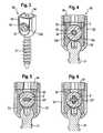
- Figs. 3 and 4show a bone anchoring element 30 which is specifically adapted for use with the rod-shaped implant.
- the bone anchoring element 30comprises a screw element 31 with a threaded shank and a spherically-shaped head and a receiving part 32 for receiving the rod-shaped implant 2.
- the receiving partis substantially cylindrical or cuboid-shaped and comprises a coaxial bore 32a which extends from one end to the opposite end and which tapers with respect to one end in order to pivotably accommodate the screw head of the screw element 31.
- the receiving part 32further comprises a U-shaped recess 32b for receiving the rod-shaped implant 2.
- a first pressure element 33is provided which is substantially cylindrical and movable in the bore. It presses onto the head of the screw element and has a U-shaped recess 33b to accommodate the rod-shaped implant 2.
- the U-shaped recess 33bhas a depth such that the pressure element extends above the surface of the rod-shaped implant 2 when the rod-shaped implant 2 is inserted.
- a fixation screw 34is provided which can be screwed into the receiving part 32 from the free ends of the U-shaped recess 32b.
- a second pressure element 35is provided which can be pressed downwards with the fixation screw 34.
- the first pressure element 33 and the second pressure element 35are shaped in such a way that the rod-shaped implant 2 is enclosed therebetween and fixed in an axial direction without pressing onto the reinforcing rod 22. Therefore, the reinforcing rod is still moveable.
- the fixation screw 34also presses onto the first pressure element 33 in order to fix the head of the screw element 31 in the receiving part, independently from the fixation of the rod-shaped implant.
- the surfaces of the first pressure element 33 and the second pressure element 35 which contact the rod-shaped implantmay have engagement structures engaging the surface of the rod without harming the surface structure of the rod-shaped implant.
- Figs. 5 and 6show variations of the cross-section of the reinforcing rod and the corresponding bore in the elastomer rod 20.
- a modified rod-shaped implant 2'is shown which differs from the rod-shaped implant 2 of the previous embodiment in that the cross-section of the reinforcing rod 22' is rectangular and the corresponding bore in the rod 20 has also a rectangular cross-section.
- the rod-shaped implant 2'is arranged such that the long side of the rectangle of the reinforcing rod 22' is aligned perpendicular to the axis of the screw element 31. However, any other orientation is possible.
- the cross-section of the reinforcing rod 2'is cross-shaped.
- cross-sections of the reinforcing rodare conceivable, for example a polygon-shaped cross-section.
- the resistance against rotational and/or shearing forces and/or bending forcescan be enhanced by using a reinforcing rod with a non-circular cross-section.
- the rod-shaped implantcan be provided with an orientation dependent bending flexibility by using a reinforcing rod with a non-circular cross-section.
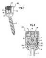
- Figs. 7 and 8show a modified bone anchoring element 300 which differs from the bone anchoring element 30 in that the pressure element 33' has a U-shaped recess 33b which has a depth such that the pressure element projects only slightly above the surface of the rod-shaped implant 2 when the rod-shaped implant is inserted.
- On the bottom of the U-shaped recessone or several pin-shaped projections 36 are provided which engage the surface of the rod-shaped implant 2.
- the fixation element 34'is a two-part fixation element with an outer screw 37 and an inner screw 38.
- the outer screw 37is screwed into the receiving part 32 and presses onto the pressure element 33' in order to lock the angular position of the screw element 31 in the receiving part.
- the inner screw 38has a pin-shaped projection 39 on its side facing the rod-shaped implant 2.
- the inner screw 38 together with the projection 36clamp the rod-shaped implant 2 independently of the fixation of the head of the screw element 31 in the receiving part 32.
- the dimension of the pin-shaped projections 36 and 39 and the dimension of the inner and outer screw of the fixation element 34'is such that only the rod 20 is clamped whereas the reinforcing rod 22 is still freely movable.
- first at least two bone anchoring elementsare inserted into the respective vertebrae. Thereafter, the necessary length of the rod-shaped implant is determined and an appropriate rod-shaped implant is cut from the rod consisting of the elastomer rod with the reinforcing rod. A stop is included at one or both ends.
- the rod-shaped implantis inserted into the receiving parts of the bone anchoring elements. Then, the vertebrae are adjusted in their position with respect to each other and the polyaxial position of the screw element 31 with respect to the receiving parts is locked. After adjusting the distances of the receiving parts the rod-shaped implant is fixed.
Landscapes
- Health & Medical Sciences (AREA)
- Orthopedic Medicine & Surgery (AREA)
- Neurology (AREA)
- Life Sciences & Earth Sciences (AREA)
- Surgery (AREA)
- Engineering & Computer Science (AREA)
- Biomedical Technology (AREA)
- General Health & Medical Sciences (AREA)
- Veterinary Medicine (AREA)
- Heart & Thoracic Surgery (AREA)
- Public Health (AREA)
- Animal Behavior & Ethology (AREA)
- Nuclear Medicine, Radiotherapy & Molecular Imaging (AREA)
- Medical Informatics (AREA)
- Molecular Biology (AREA)
- Surgical Instruments (AREA)
- Prostheses (AREA)
- Vascular Medicine (AREA)
- Transplantation (AREA)
- Oral & Maxillofacial Surgery (AREA)
- Cardiology (AREA)
Description
- The invention relates to a rod-shaped implant in particular for stabilizing the spinal column and to a spinal stabilization device including such a rod-shaped implant. The rod-shaped implant includes a flexible rod made at least partly of an elastomer material and further includes a reinforcing rod for strengthening the implant in particular against rotational movements of the spinal column in an axial direction and against shearing forces. The spinal stabilization system is comprised of such a rod-shaped implant and of at least two bone anchoring elements to be connected to the rod-shaped implant.
EP 0 669 109 B1 discloses a stabilizing apparatus for stabilizing neighbouring thoracic vertebrae. The apparatus comprises two monaxial pedicle screws and a strap that is fixed in the receiver member of each pedicle screw by means of a clamping screw and a support element that is mounted on the strap and is designed as a pressure resistant body. The stabilization apparatus, however, fails to be torsionally stiff and does not allow for axial extension. In addition, the use of monoaxial pedicle screws limits the application of this stabilization apparatus.US 2007/0093820 A1 discloses a dynamic spinal stabilization comprising a flexible rod made of an elastomer material which is clamped in the receiving parts of monoaxial bone screws.EP 1 795 134 A1 andEP 1 900 334 A1 describe a spinal stabilization system with a flexible elastomer rod and polyaxial bone screws.- The dynamic stabilization systems comprising a flexible elastomer rod are suitable for the control, in particular the damping, of axial compression and extension of motion segments of the spinal column. The elastomer material is advantageous with respect to obtaining the suitable length of the rod-shaped implant by cutting an elastomer rod and the implant is simple to manufacture.
- In clinical cases of early degeneration or partial damages or injuries of intervertebral discs the corresponding motion segments of the spinal column are subject to increased rotational movements and shearing forces. Such rotational movements and shearing forces can cause strong pain.
US 2007/049937 A1 discloses a rod-shaped implant which comprises a metallic hollow rod with a flexible section in form of a helix-shaped recess in wall of the rod. In the hollow rod a longitudinal core is provided which can be fixed with respect to one end of the rod and which can be moveable with respect to the other end of the rod. The problem of kinking of the rod-shaped implant caused by shearing movements of the spinal column is considerably reduced.- Document
EP 1 891 904 A1 discloses a rod-shaped implant in a bone anchoring device. The implant comprises a rod formed as a tube including a bore. Inside the bore a core is slidably accommodated. The core has an enhanced stiffness to avoid kinking of the flexible rod. Further, the rod can be made of a plastic material. - It is an object of the invention to provide an implant and a stabilization system for the spinal column which is particularly suited for cases in which rotational and shearing movements of the spinal column shall be suppressed.
- The object is solved by an implant according to claim 1 and by a stabilization system according to claim 12. Further developments are given in the dependent claims.
- The rod-shaped implant according to the invention has the advantages of elastomer rods such as facilitated manufacture and handling but has enhanced stability compared to purely elastomeric rods and is a modular system allowing various combinations of elastomeric rods and reinforcing rods.
- The rod-shaped implant and the stabilization system allows a dynaming damping of the axial tension and compression movements by using the elastomer rod and considerably enhances the resistance against rotational and/or shearing and/or bending movements due to the reinforcing rod.
- Further features and advantages will become apparent from the detailed description of embodiments by means of the accompanying drawings.
- In the drawings:
- Fig. 1
- shows a schematic sectional view of the stabilization system, the section being taken along the rod axis.
- Fig. 2
- shows a schematic side view of the stabilization system.
- Fig. 3
- shows a schematic perspective view of a bone anchoring element which is adapted to the rod-shaped implant.
- Fig. 4
- shows a schematic sectional view of the bone anchoring element of
Fig. 3 with an inserted rod-shaped implant, the section being taken perpendicular to the rod axis. - Fig. 5
- shows a schematic sectional view of the bone anchoring element of
Fig. 3 with a modified rod-shaped rod-implant. - Fig. 6
- shows a schematic sectional view of the bone anchoring element of
Fig. 3 with a still further modified rod-shaped implant. - Fig. 7
- shows a schematic perspective view of a bone anchoring element which is modified concerning the adaptation to the rod-shaped implant.
- Fig. 8
- shows a schematic sectional view of the bone anchoring element of
Fig. 7 with the rod-shaped implant inserted, the section being taken perpendicular to the rod axis. - As shown in
Figs. 1 and 2 , the stabilization device 1 comprises a rod-shaped implant 2 and a plurality ofbone anchoring elements 3. The bone anchoring elements can be anchored in bony structures, in particular in adjacent vertebrae of the spinal column. The rod-shaped implant 2 can be connected to the bone anchoring elements so that it is anchored in the vertebrae. Hence, the total length of the rod-shaped implant 2 is such that it spans the distance of at least two vertebrae of the spinal column. - In the embodiment shown, the rod-shape implant is formed of a
cylindrical rod 20 comprising afirst end 2a and asecond end 2b. Acoaxial bore 21 extends from thefirst end 2a to the second 2b through thecylindrical rod 20. In this embodiment the coaxial bore has a circular cross section. - In the coaxial bore 21 a reinforcing
rod 22 is accommodated which has a circular cross section and a diameter which is sized such that the reinforcingrod 22 can slide within thecoaxial bore 21. Thereinforcing rod 22 extends from thefirst end 2a to at least thesecond end 2b and may project beyondsecond end 2b of thecylindrical rod 20. At one end, for example at thefirst end 2a, the reinforcingrod 22 is limited with respect to its movement relative to therod 20 by means of astop 23. Thestop 23 can be formed, for example, as a disc which is mounted to the end of the reinforcing rod. Other constructions for thestop 23 are conceivable. Although not shown in the figures, the stop is adjustable along an end portion of the reinforcingrod 22. This can be realized, for example, by providing a thread on the outer surface of the end portion of the reinforcingrod 22 and by providing a nut to be screwed on the threaded end portion which abuts against theend 2a of the cylindrical rod 22 (not shown). - The reinforcing rod is movable at the
second end 2b. However, a second stop (not shown) can be provided also at a distance from thesecond end 2b. The second stop may be adjustable. If a second stop is provided, the distance between the first stop and the second stop is greater than the distance between thefirst end 2a and thesecond end 2b so that the reinforcingrod 22 is freely movable. - The material of the
rod 20 is a plastic material which exhibits flexibility when therod 20 experiences compression or tension forces acting in axial direction. Particularly suitable are polymer materials exhibiting such flexibility, preferably elastomer materials such as polyurethanes, polycarbonate urethanes (PCU) or polysiloxanes. Any other material exhibiting such elastic features is, however, suitable. Since the material exhibits flexible properties, thecylindrical rod 20 also reacts on rotational forces around the rod axis and on shearing forces having a component perpendicular to the rod axis. Such forces arise from torsional and shearing motions of the motion segments of the spine. - In order to control and dampen such rotational and shearing forces the reinforcing
rod 22 is made from a material which is less flexible than thecylindrical rod 20 or which exhibits no flexibility under forces acting along the rod axis. Particularly suitable materials are body compatible metals, such as stainless steel or titanium or titanium alloys, such as Nitinol, or rigid plastic materials, for example PEEK or carbon fiber reinforced PEEK or others. - The reinforcing
rod 22 can be coated to facilitate sliding within the coaxial bore of thecylindrical rod 20. Alternatively a sliding guidance or a sliding bearing can be provided to facilitate sliding of the reinforcing rod. - The
bone anchoring element 3 can be any monoaxial bone screw or bone hook, but is preferably a polyaxial bone screw as depicted inFigs. 1 and 2 . Thepolyaxial bone screw 3 comprises ascrew element 31 with a threaded shank and a spherically shaped head which is pivotably held in a receivingpart 32 which receives the rod. To fix thescrew element 31 in a desired angular position with respect to the receivingpart 32 apressure element 33 acting onto the head of thescrew element 31 is provided. The rod-shapedimplant 2 is received in the receivingpart 32 and is fixed by means of afixation element 34. Figs. 3 and 4 show abone anchoring element 30 which is specifically adapted for use with the rod-shaped implant. Thebone anchoring element 30 comprises ascrew element 31 with a threaded shank and a spherically-shaped head and a receivingpart 32 for receiving the rod-shapedimplant 2. The receiving part is substantially cylindrical or cuboid-shaped and comprises acoaxial bore 32a which extends from one end to the opposite end and which tapers with respect to one end in order to pivotably accommodate the screw head of thescrew element 31. The receivingpart 32 further comprises aU-shaped recess 32b for receiving the rod-shapedimplant 2.- A
first pressure element 33 is provided which is substantially cylindrical and movable in the bore. It presses onto the head of the screw element and has aU-shaped recess 33b to accommodate the rod-shapedimplant 2. TheU-shaped recess 33b has a depth such that the pressure element extends above the surface of the rod-shapedimplant 2 when the rod-shapedimplant 2 is inserted. - A
fixation screw 34 is provided which can be screwed into the receivingpart 32 from the free ends of theU-shaped recess 32b. - Furthermore, a
second pressure element 35 is provided which can be pressed downwards with thefixation screw 34. - The
first pressure element 33 and thesecond pressure element 35 are shaped in such a way that the rod-shapedimplant 2 is enclosed therebetween and fixed in an axial direction without pressing onto the reinforcingrod 22. Therefore, the reinforcing rod is still moveable. Thefixation screw 34 also presses onto thefirst pressure element 33 in order to fix the head of thescrew element 31 in the receiving part, independently from the fixation of the rod-shaped implant. - The surfaces of the
first pressure element 33 and thesecond pressure element 35 which contact the rod-shaped implant may have engagement structures engaging the surface of the rod without harming the surface structure of the rod-shaped implant. Figs. 5 and 6 show variations of the cross-section of the reinforcing rod and the corresponding bore in theelastomer rod 20. InFig. 5 a modified rod-shaped implant 2' is shown which differs from the rod-shapedimplant 2 of the previous embodiment in that the cross-section of the reinforcing rod 22' is rectangular and the corresponding bore in therod 20 has also a rectangular cross-section. In the embodiment shown inFig. 5 the rod-shaped implant 2' is arranged such that the long side of the rectangle of the reinforcing rod 22' is aligned perpendicular to the axis of thescrew element 31. However, any other orientation is possible. In the modification shown inFig. 6 the cross-section of the reinforcing rod 2' is cross-shaped.- Other cross-sections of the reinforcing rod are conceivable, for example a polygon-shaped cross-section. The resistance against rotational and/or shearing forces and/or bending forces can be enhanced by using a reinforcing rod with a non-circular cross-section. In addition, if necessary, the rod-shaped implant can be provided with an orientation dependent bending flexibility by using a reinforcing rod with a non-circular cross-section.
Figs. 7 and 8 show a modifiedbone anchoring element 300 which differs from thebone anchoring element 30 in that the pressure element 33' has aU-shaped recess 33b which has a depth such that the pressure element projects only slightly above the surface of the rod-shapedimplant 2 when the rod-shaped implant is inserted. On the bottom of the U-shaped recess one or several pin-shapedprojections 36 are provided which engage the surface of the rod-shapedimplant 2.- The fixation element 34' is a two-part fixation element with an
outer screw 37 and aninner screw 38. Theouter screw 37 is screwed into the receivingpart 32 and presses onto the pressure element 33' in order to lock the angular position of thescrew element 31 in the receiving part. Theinner screw 38 has a pin-shapedprojection 39 on its side facing the rod-shapedimplant 2. Theinner screw 38 together with theprojection 36 clamp the rod-shapedimplant 2 independently of the fixation of the head of thescrew element 31 in the receivingpart 32. The dimension of the pin-shapedprojections rod 20 is clamped whereas the reinforcingrod 22 is still freely movable. - In use, first at least two bone anchoring elements are inserted into the respective vertebrae. Thereafter, the necessary length of the rod-shaped implant is determined and an appropriate rod-shaped implant is cut from the rod consisting of the elastomer rod with the reinforcing rod. A stop is included at one or both ends.
- Thereafter, the rod-shaped implant is inserted into the receiving parts of the bone anchoring elements. Then, the vertebrae are adjusted in their position with respect to each other and the polyaxial position of the
screw element 31 with respect to the receiving parts is locked. After adjusting the distances of the receiving parts the rod-shaped implant is fixed.
Claims (12)
- A rod-shaped implant for stabilizing bone structures, in particular the spinal column, the rod-shaped implant (2, 2', 2"), comprising
a rod-member (20) having a first end (2a) and a second end (2b) and a longitudinal axis, the rod-member being at least partly made from an elastomer material exhibiting flexibility,
a longitudinal bore (21) provided in the rod-member,
a reinforcing rod-member (22, 22', 22") accommodated in the bore (21) which is made from a more rigid material than the material of the rod-member itself, wherein the reinforcing rod-member is slidable in the bore, and
a first stop (23) provided to an end portion of the reinforcing rod-member which limits the relative sliding movement of the end portion of the reinforcing rod-member (22, 22', 22") with respect to the first end (2a) of the rod-member,
characterised in that the first stop (23) is adjustable along the end portion of the reinforcing rod member (22, 22', 22"). - The rod-shaped implant of claim 1, wherein a second stop is provided at another portion of the reinforcing rod member (22, 22', 22") in a distance from the second end (2b) of the rod-member (20), wherein the distance between the first stop (23) and the second stop is greater than the distance between the first end (2a) and the second end (2b) so that the reinforcing rod member (22, 22', 22") is freely movable at the second end (2b) of the rod-member, and
wherein the second stop is adjustable along the other portion of the reinforcing rod member (22, 22', 22"). - The rod-shaped implant of claim 1, wherein the reinforcing rod-member is made of a body compatible metal or a body compatible rigid plastic material.
- The rod-shaped implant of one of claims 1, 2 or 3, wherein the bore extends from the first end to the second end.
- The rod-shaped implant according to one of claims 1 to 4, wherein the rod-member (20) is as a whole made of the elastomer material.
- The rod-shaped implant according to one of claims 1 to 5, wherein the cross-section of the reinforcing rod-member (22', 22") is non-circular.
- The rod-shaped implant according to one of claims 1 to 6, wherein the material of the rod-member exhibits flexibility under the action of compression and extension forces along the longitudinal axis.
- The rod-shaped implant according to one of claims 1 to 7, wherein means for facilitating sliding of the reinforcing rod are provided.
- A spinal stabilization device including a rod-shaped implant (2) according to one of claims 1 to 8, and at least two bone anchoring elements (3) to be connected to the rod-shaped implant.
- The spinal stabilization device according to claim 9, wherein at least one of the bone anchoring elements is a polyaxial screw (3) comprising a screw element (31) which can be pivoted in a receiving part (32) which receives the rod-shaped implant (2).
- The spinal stabilization device according to claim 10 wherein the polyaxial screw is designed such that the position of the screw element (31) with respect to the receiving part (32) can be locked independently from the fixation of the rod-shaped implant (2).
- The spinal stabilisation device according to one of claims 9 to 11 wherein the rod-shaped implant (2) is fixed in such a way that the reinforcing rod is still movable when the rod-member (20) is clamped.
Priority Applications (7)
| Application Number | Priority Date | Filing Date | Title |
|---|---|---|---|
| EP08015662AEP2160988B1 (en) | 2008-09-04 | 2008-09-04 | Rod-shaped implant in particular for stabilizing the spinal column and stabilization device including such a rod-shaped implant |
| ES08015662TES2402078T3 (en) | 2008-09-04 | 2008-09-04 | Rod-shaped implant, in particular to stabilize the spine, and stabilization device that includes such a rod-shaped implant |
| US12/550,960US9451988B2 (en) | 2008-09-04 | 2009-08-31 | Rod-shaped implant in particular for stabilizing the spinal column and stabilization device including such a rod-shaped implant |
| TW098129327ATWI480020B (en) | 2008-09-04 | 2009-09-01 | Rod-shaped implant in particular for stabilizing the spinal column and stabilization device including such a rod-shaped implant |
| JP2009201674AJP2010057917A (en) | 2008-09-04 | 2009-09-01 | Rod-shaped implant and spinal column stabilization device |
| KR1020090082166AKR20100028484A (en) | 2008-09-04 | 2009-09-01 | Rod-shaped implant in particular for stabilizing the spinal column and stabilization device including such a rod-shaped implant |
| CN200910170662.2ACN101664334B (en) | 2008-09-04 | 2009-09-01 | Stabilization device including rod-shaped implant |
Applications Claiming Priority (2)
| Application Number | Priority Date | Filing Date | Title |
|---|---|---|---|
| US9420708P | 2008-09-04 | 2008-09-04 | |
| EP08015662AEP2160988B1 (en) | 2008-09-04 | 2008-09-04 | Rod-shaped implant in particular for stabilizing the spinal column and stabilization device including such a rod-shaped implant |
Publications (2)
| Publication Number | Publication Date |
|---|---|
| EP2160988A1 EP2160988A1 (en) | 2010-03-10 |
| EP2160988B1true EP2160988B1 (en) | 2012-12-26 |
Family
ID=40006842
Family Applications (1)
| Application Number | Title | Priority Date | Filing Date |
|---|---|---|---|
| EP08015662ANot-in-forceEP2160988B1 (en) | 2008-09-04 | 2008-09-04 | Rod-shaped implant in particular for stabilizing the spinal column and stabilization device including such a rod-shaped implant |
Country Status (6)
| Country | Link |
|---|---|
| US (1) | US9451988B2 (en) |
| EP (1) | EP2160988B1 (en) |
| JP (1) | JP2010057917A (en) |
| KR (1) | KR20100028484A (en) |
| CN (1) | CN101664334B (en) |
| TW (1) | TWI480020B (en) |
Families Citing this family (68)
| Publication number | Priority date | Publication date | Assignee | Title |
|---|---|---|---|---|
| US7833250B2 (en) | 2004-11-10 | 2010-11-16 | Jackson Roger P | Polyaxial bone screw with helically wound capture connection |
| US8353932B2 (en) | 2005-09-30 | 2013-01-15 | Jackson Roger P | Polyaxial bone anchor assembly with one-piece closure, pressure insert and plastic elongate member |
| US10729469B2 (en) | 2006-01-09 | 2020-08-04 | Roger P. Jackson | Flexible spinal stabilization assembly with spacer having off-axis core member |
| US10258382B2 (en) | 2007-01-18 | 2019-04-16 | Roger P. Jackson | Rod-cord dynamic connection assemblies with slidable bone anchor attachment members along the cord |
| US7862587B2 (en) | 2004-02-27 | 2011-01-04 | Jackson Roger P | Dynamic stabilization assemblies, tool set and method |
| US8292926B2 (en) | 2005-09-30 | 2012-10-23 | Jackson Roger P | Dynamic stabilization connecting member with elastic core and outer sleeve |
| US8876868B2 (en) | 2002-09-06 | 2014-11-04 | Roger P. Jackson | Helical guide and advancement flange with radially loaded lip |
| US7621918B2 (en) | 2004-11-23 | 2009-11-24 | Jackson Roger P | Spinal fixation tool set and method |
| US7377923B2 (en) | 2003-05-22 | 2008-05-27 | Alphatec Spine, Inc. | Variable angle spinal screw assembly |
| US7766915B2 (en) | 2004-02-27 | 2010-08-03 | Jackson Roger P | Dynamic fixation assemblies with inner core and outer coil-like member |
| US8926670B2 (en) | 2003-06-18 | 2015-01-06 | Roger P. Jackson | Polyaxial bone screw assembly |
| US7776067B2 (en) | 2005-05-27 | 2010-08-17 | Jackson Roger P | Polyaxial bone screw with shank articulation pressure insert and method |
| US7179261B2 (en) | 2003-12-16 | 2007-02-20 | Depuy Spine, Inc. | Percutaneous access devices and bone anchor assemblies |
| US11419642B2 (en) | 2003-12-16 | 2022-08-23 | Medos International Sarl | Percutaneous access devices and bone anchor assemblies |
| US7527638B2 (en) | 2003-12-16 | 2009-05-05 | Depuy Spine, Inc. | Methods and devices for minimally invasive spinal fixation element placement |
| JP2007525274A (en) | 2004-02-27 | 2007-09-06 | ロジャー・ピー・ジャクソン | Orthopedic implant rod reduction instrument set and method |
| US8152810B2 (en) | 2004-11-23 | 2012-04-10 | Jackson Roger P | Spinal fixation tool set and method |
| US7160300B2 (en) | 2004-02-27 | 2007-01-09 | Jackson Roger P | Orthopedic implant rod reduction tool set and method |
| US11241261B2 (en) | 2005-09-30 | 2022-02-08 | Roger P Jackson | Apparatus and method for soft spinal stabilization using a tensionable cord and releasable end structure |
| US7651502B2 (en) | 2004-09-24 | 2010-01-26 | Jackson Roger P | Spinal fixation tool set and method for rod reduction and fastener insertion |
| US8926672B2 (en) | 2004-11-10 | 2015-01-06 | Roger P. Jackson | Splay control closure for open bone anchor |
| US20120029568A1 (en)* | 2006-01-09 | 2012-02-02 | Jackson Roger P | Spinal connecting members with radiused rigid sleeves and tensioned cords |
| WO2006057837A1 (en) | 2004-11-23 | 2006-06-01 | Jackson Roger P | Spinal fixation tool attachment structure |
| US9216041B2 (en) | 2009-06-15 | 2015-12-22 | Roger P. Jackson | Spinal connecting members with tensioned cords and rigid sleeves for engaging compression inserts |
| US9168069B2 (en) | 2009-06-15 | 2015-10-27 | Roger P. Jackson | Polyaxial bone anchor with pop-on shank and winged insert with lower skirt for engaging a friction fit retainer |
| US8444681B2 (en) | 2009-06-15 | 2013-05-21 | Roger P. Jackson | Polyaxial bone anchor with pop-on shank, friction fit retainer and winged insert |
| US7901437B2 (en) | 2007-01-26 | 2011-03-08 | Jackson Roger P | Dynamic stabilization member with molded connection |
| US8105368B2 (en) | 2005-09-30 | 2012-01-31 | Jackson Roger P | Dynamic stabilization connecting member with slitted core and outer sleeve |
| CA2670988C (en) | 2006-12-08 | 2014-03-25 | Roger P. Jackson | Tool system for dynamic spinal implants |
| FR2910267B1 (en)* | 2006-12-21 | 2009-01-23 | Ldr Medical Soc Par Actions Si | VERTEBRAL SUPPORT DEVICE |
| US8366745B2 (en) | 2007-05-01 | 2013-02-05 | Jackson Roger P | Dynamic stabilization assembly having pre-compressed spacers with differential displacements |
| US8475498B2 (en) | 2007-01-18 | 2013-07-02 | Roger P. Jackson | Dynamic stabilization connecting member with cord connection |
| US8979904B2 (en) | 2007-05-01 | 2015-03-17 | Roger P Jackson | Connecting member with tensioned cord, low profile rigid sleeve and spacer with torsion control |
| US10383660B2 (en) | 2007-05-01 | 2019-08-20 | Roger P. Jackson | Soft stabilization assemblies with pretensioned cords |
| US20110172708A1 (en)* | 2007-06-22 | 2011-07-14 | Simpirica Spine, Inc. | Methods and systems for increasing the bending stiffness of a spinal segment with elongation limit |
| EP2441404B1 (en)* | 2008-04-28 | 2013-07-31 | Biedermann Technologies GmbH & Co. KG | Rod-shaped implant, in particular for spinal stabilization, and method for producing the same |
| AU2010260521C1 (en) | 2008-08-01 | 2013-08-01 | Roger P. Jackson | Longitudinal connecting member with sleeved tensioned cords |
| EP2484300B1 (en)* | 2008-09-05 | 2015-05-20 | Biedermann Technologies GmbH & Co. KG | Stabilization device for bones, in particular for the spinal column |
| US9408649B2 (en)* | 2008-09-11 | 2016-08-09 | Innovasis, Inc. | Radiolucent screw with radiopaque marker |
| CN103826560A (en) | 2009-06-15 | 2014-05-28 | 罗杰.P.杰克逊 | Polyaxial Bone Anchor with Socket Stem and Winged Inserts with Friction Fit Compression Collars |
| US9668771B2 (en) | 2009-06-15 | 2017-06-06 | Roger P Jackson | Soft stabilization assemblies with off-set connector |
| US8998959B2 (en) | 2009-06-15 | 2015-04-07 | Roger P Jackson | Polyaxial bone anchors with pop-on shank, fully constrained friction fit retainer and lock and release insert |
| US11229457B2 (en) | 2009-06-15 | 2022-01-25 | Roger P. Jackson | Pivotal bone anchor assembly with insert tool deployment |
| US9320543B2 (en)* | 2009-06-25 | 2016-04-26 | DePuy Synthes Products, Inc. | Posterior dynamic stabilization device having a mobile anchor |
| EP2279705A1 (en)* | 2009-07-28 | 2011-02-02 | Spinelab AG | Spinal implant |
| US9433439B2 (en)* | 2009-09-10 | 2016-09-06 | Innovasis, Inc. | Radiolucent stabilizing rod with radiopaque marker |
| EP2485654B1 (en) | 2009-10-05 | 2021-05-05 | Jackson P. Roger | Polyaxial bone anchor with non-pivotable retainer and pop-on shank, some with friction fit |
| FR2959113B1 (en)* | 2010-04-23 | 2013-04-12 | Smartspine | POLAR PEDICULAR SCREW AND PEDICULAR FIXING DEVICE FOR APPLYING FOR VERTEBRAL OSTEOSYNTHESIS |
| AU2011299558A1 (en) | 2010-09-08 | 2013-05-02 | Roger P. Jackson | Dynamic stabilization members with elastic and inelastic sections |
| US8585703B2 (en)* | 2010-12-09 | 2013-11-19 | Stryker Trauma Sa | Adjustment tool for external fixator |
| AU2011342906B2 (en)* | 2010-12-15 | 2016-03-03 | Pinczewski, Leo | Peek-rich bone screw |
| ES2461843T3 (en)* | 2010-12-23 | 2014-05-21 | Biedermann Technologies Gmbh & Co. Kg | Bone anchoring device |
| EP2554130B1 (en)* | 2011-08-05 | 2014-05-28 | Biedermann Technologies GmbH & Co. KG | Locking device for locking a rod-shaped element in a receiving part of a bone anchor and bone anchor with such a locking device |
| EP2574296B1 (en)* | 2011-09-28 | 2016-03-02 | Biedermann Technologies GmbH & Co. KG | Bone anchoring assembly |
| US8911479B2 (en) | 2012-01-10 | 2014-12-16 | Roger P. Jackson | Multi-start closures for open implants |
| KR200466455Y1 (en)* | 2012-11-12 | 2013-04-16 | 차종학 | vertebra implant |
| US8911478B2 (en) | 2012-11-21 | 2014-12-16 | Roger P. Jackson | Splay control closure for open bone anchor |
| US10058354B2 (en) | 2013-01-28 | 2018-08-28 | Roger P. Jackson | Pivotal bone anchor assembly with frictional shank head seating surfaces |
| US8852239B2 (en) | 2013-02-15 | 2014-10-07 | Roger P Jackson | Sagittal angle screw with integral shank and receiver |
| US9566092B2 (en) | 2013-10-29 | 2017-02-14 | Roger P. Jackson | Cervical bone anchor with collet retainer and outer locking sleeve |
| US9717533B2 (en) | 2013-12-12 | 2017-08-01 | Roger P. Jackson | Bone anchor closure pivot-splay control flange form guide and advancement structure |
| US9451993B2 (en) | 2014-01-09 | 2016-09-27 | Roger P. Jackson | Bi-radial pop-on cervical bone anchor |
| US10064658B2 (en) | 2014-06-04 | 2018-09-04 | Roger P. Jackson | Polyaxial bone anchor with insert guides |
| US9597119B2 (en) | 2014-06-04 | 2017-03-21 | Roger P. Jackson | Polyaxial bone anchor with polymer sleeve |
| CN104306056A (en)* | 2014-07-07 | 2015-01-28 | 吴爱悯 | Jumping type spine dynamic fixing device |
| EP3766443B1 (en) | 2019-07-18 | 2023-02-15 | Biedermann Technologies GmbH & Co. KG | Bone anchoring device |
| RU195374U1 (en)* | 2019-10-14 | 2020-01-23 | Ольга Алексеевна Борисова | Universal axial shaft for transpedicular fixation of the spine |
| EP3871624B1 (en) | 2020-02-25 | 2023-07-19 | Biedermann Technologies GmbH & Co. KG | Bone anchoring device |
Family Cites Families (50)
| Publication number | Priority date | Publication date | Assignee | Title |
|---|---|---|---|---|
| ATE180402T1 (en) | 1994-02-28 | 1999-06-15 | Sulzer Orthopaedie Ag | STABILIZATION OF ADJACENT BACK VERTEBRATE |
| DE10236691B4 (en)* | 2002-08-09 | 2005-12-01 | Biedermann Motech Gmbh | Dynamic stabilization device for bones, in particular for vertebrae |
| WO2004096066A2 (en)* | 2003-04-25 | 2004-11-11 | Kitchen Michael S | Spinal curvature correction device |
| DE10326517A1 (en) | 2003-06-12 | 2005-01-05 | Stratec Medical | Device for the dynamic stabilization of bones or bone fragments, in particular vertebrae |
| US7766915B2 (en)* | 2004-02-27 | 2010-08-03 | Jackson Roger P | Dynamic fixation assemblies with inner core and outer coil-like member |
| US7799082B2 (en)* | 2003-08-05 | 2010-09-21 | Flexuspine, Inc. | Artificial functional spinal unit system and method for use |
| US20050203513A1 (en)* | 2003-09-24 | 2005-09-15 | Tae-Ahn Jahng | Spinal stabilization device |
| US7763052B2 (en) | 2003-12-05 | 2010-07-27 | N Spine, Inc. | Method and apparatus for flexible fixation of a spine |
| US7137985B2 (en) | 2003-09-24 | 2006-11-21 | N Spine, Inc. | Marking and guidance method and system for flexible fixation of a spine |
| US20050085185A1 (en)* | 2003-10-06 | 2005-04-21 | Patterson Steven C. | Method and apparatus for focusing sound |
| DE10348329B3 (en)* | 2003-10-17 | 2005-02-17 | Biedermann Motech Gmbh | Rod-shaped element used in spinal column and accident surgery for connecting two bone-anchoring elements comprises a rigid section and an elastic section that are made in one piece |
| JP2007508085A (en) | 2003-10-17 | 2007-04-05 | ヴィーダーマン モテッヒ ゲーエムベーハー | Flexible implant |
| US8632570B2 (en) | 2003-11-07 | 2014-01-21 | Biedermann Technologies Gmbh & Co. Kg | Stabilization device for bones comprising a spring element and manufacturing method for said spring element |
| FR2867057B1 (en)* | 2004-03-02 | 2007-06-01 | Spinevision | DYNAMIC BONDING ELEMENT FOR A SPINAL FIXING SYSTEM AND FIXING SYSTEM COMPRISING SUCH A CONNECTING MEMBER |
| CA2558419A1 (en) | 2004-03-04 | 2005-09-15 | Synthes Gmbh | Connecting rod for bone connecting elements |
| DE102004011685A1 (en)* | 2004-03-09 | 2005-09-29 | Biedermann Motech Gmbh | Spine supporting element, comprising spiraled grooves at outer surface and three plain areas |
| US7854752B2 (en)* | 2004-08-09 | 2010-12-21 | Theken Spine, Llc | System and method for dynamic skeletal stabilization |
| US20060058788A1 (en)* | 2004-08-27 | 2006-03-16 | Hammer Michael A | Multi-axial connection system |
| US20060247638A1 (en) | 2005-04-29 | 2006-11-02 | Sdgi Holdings, Inc. | Composite spinal fixation systems |
| US20060264935A1 (en)* | 2005-05-04 | 2006-11-23 | White Patrick M | Orthopedic stabilization device |
| US7828825B2 (en)* | 2005-06-20 | 2010-11-09 | Warsaw Orthopedic, Inc. | Multi-level multi-functional spinal stabilization systems and methods |
| DE602005007223D1 (en)* | 2005-08-24 | 2008-07-10 | Biedermann Motech Gmbh | Rod-shaped element for use in spine or trauma surgery and stabilization device with such an element |
| CH705709B1 (en) | 2005-08-29 | 2013-05-15 | Bird Biedermann Ag | Spinal implant. |
| US20090093844A1 (en)* | 2005-09-30 | 2009-04-09 | Jackson Roger P | Elastic covered dynamic stabilization connector and assembly |
| ES2313189T3 (en) | 2005-11-17 | 2009-03-01 | Biedermann Motech Gmbh | POLIAXIAL SCREW FOR FLEXIBLE BAR. |
| WO2007061960A2 (en)* | 2005-11-18 | 2007-05-31 | Life Spine, Inc. | Dynamic spinal stabilization devices and systems |
| US20070233064A1 (en) | 2006-02-17 | 2007-10-04 | Holt Development L.L.C. | Apparatus and method for flexible spinal fixation |
| US20080269804A1 (en) | 2006-02-17 | 2008-10-30 | Holt Development L.L.C. | Apparatus and method for flexible spinal fixation |
| US20070233073A1 (en) | 2006-03-02 | 2007-10-04 | Sdgi Holdings, Inc. | Spinal rod characterized by a time-varying stiffness |
| US20070225707A1 (en) | 2006-03-22 | 2007-09-27 | Sdgi Holdings, Inc. | Orthopedic spinal devices fabricated from two or more materials |
| JP5210305B2 (en)* | 2006-06-16 | 2013-06-12 | アルファテック スパイン, インコーポレイテッド | Spinal screw assembly system, system for implanting spinal screw assembly |
| EP1891904B1 (en)* | 2006-08-24 | 2013-12-25 | Biedermann Technologies GmbH & Co. KG | Bone anchoring device |
| ES2336815T5 (en) | 2006-09-15 | 2013-05-16 | Biedermann Technologies Gmbh & Co. Kg | Bone anchoring device |
| US20080125777A1 (en) | 2006-11-27 | 2008-05-29 | Warsaw Orthopedic, Inc. | Vertebral Stabilizer Having Adjustable Rigidity |
| FR2910267B1 (en)* | 2006-12-21 | 2009-01-23 | Ldr Medical Soc Par Actions Si | VERTEBRAL SUPPORT DEVICE |
| US8109975B2 (en)* | 2007-01-30 | 2012-02-07 | Warsaw Orthopedic, Inc. | Collar bore configuration for dynamic spinal stabilization assembly |
| US8029547B2 (en) | 2007-01-30 | 2011-10-04 | Warsaw Orthopedic, Inc. | Dynamic spinal stabilization assembly with sliding collars |
| WO2009026519A1 (en)* | 2007-08-23 | 2009-02-26 | Life Spine Inc. | Resilient spinal rod system with controllable angulation |
| US20090099608A1 (en)* | 2007-10-12 | 2009-04-16 | Aesculap Implant Systems, Inc. | Rod assembly for dynamic posterior stabilization |
| US20100318130A1 (en)* | 2007-12-15 | 2010-12-16 | Parlato Brian D | Flexible rod assembly for spinal fixation |
| CN201303976Y (en)* | 2008-02-28 | 2009-09-09 | 天津市圣格生物工程有限公司 | Elastic dynamic intraspinal fixing system |
| US20090234388A1 (en)* | 2008-03-15 | 2009-09-17 | Warsaw Orthopedic, Inc. | Spinal Stabilization Connecting Element and System |
| US20090326582A1 (en)* | 2008-04-10 | 2009-12-31 | Marcus Songer | Dynamic Rod |
| US20090259257A1 (en)* | 2008-04-15 | 2009-10-15 | Warsaw Orthopedic, Inc. | Pedicule-Based Motion- Preserving Device |
| US8430912B2 (en)* | 2008-05-05 | 2013-04-30 | Warsaw Orthopedic, Inc. | Dynamic stabilization rod |
| US8043340B1 (en)* | 2008-06-09 | 2011-10-25 | Melvin Law | Dynamic spinal stabilization system |
| US20090326584A1 (en)* | 2008-06-27 | 2009-12-31 | Michael Andrew Slivka | Spinal Dynamic Stabilization Rods Having Interior Bumpers |
| EP2198792A1 (en)* | 2008-12-19 | 2010-06-23 | Sepitec Foundation | Implant system for stabilising bones |
| US20100211105A1 (en)* | 2009-02-13 | 2010-08-19 | Missoum Moumene | Telescopic Rod For Posterior Dynamic Stabilization |
| EP2279705A1 (en)* | 2009-07-28 | 2011-02-02 | Spinelab AG | Spinal implant |
- 2008
- 2008-09-04EPEP08015662Apatent/EP2160988B1/ennot_activeNot-in-force
- 2009
- 2009-08-31USUS12/550,960patent/US9451988B2/ennot_activeExpired - Fee Related
- 2009-09-01CNCN200910170662.2Apatent/CN101664334B/ennot_activeExpired - Fee Related
- 2009-09-01KRKR1020090082166Apatent/KR20100028484A/ennot_activeCeased
- 2009-09-01TWTW098129327Apatent/TWI480020B/enactive
- 2009-09-01JPJP2009201674Apatent/JP2010057917A/enactivePending
Also Published As
| Publication number | Publication date |
|---|---|
| KR20100028484A (en) | 2010-03-12 |
| TW201010664A (en) | 2010-03-16 |
| JP2010057917A (en) | 2010-03-18 |
| CN101664334A (en) | 2010-03-10 |
| CN101664334B (en) | 2014-03-05 |
| US9451988B2 (en) | 2016-09-27 |
| TWI480020B (en) | 2015-04-11 |
| US20100087863A1 (en) | 2010-04-08 |
| EP2160988A1 (en) | 2010-03-10 |
Similar Documents
| Publication | Publication Date | Title |
|---|---|---|
| EP2160988B1 (en) | Rod-shaped implant in particular for stabilizing the spinal column and stabilization device including such a rod-shaped implant | |
| EP2160989B1 (en) | Stabilization device for bones, in particular for the spinal column | |
| EP2055251B1 (en) | Bone anchoring element | |
| US7601166B2 (en) | Stabilization device for the dynamic stabilization of vertebrae or bones and rod like element for such a stabilization device | |
| EP2105101B1 (en) | Bone anchoring device | |
| US8795336B2 (en) | Bone anchoring device and stabilization device for bone parts or vertebrae comprising such a bone anchoring device | |
| EP1857065B1 (en) | Longitudinal member for use in spinal or trauma surgery | |
| US7621940B2 (en) | Rod-like element for application in spinal or trauma surgery, and stabilization device with such a rod-like element | |
| EP2364656B1 (en) | Rod assembly and modular rod system for spinal stabilization | |
| EP2116205B1 (en) | Rod-shaped implant, in particular for the dynamic stabilization of the spine | |
| EP2153786B1 (en) | Modular system for the stabilization of the spinal column | |
| ES2402078T3 (en) | Rod-shaped implant, in particular to stabilize the spine, and stabilization device that includes such a rod-shaped implant |
Legal Events
| Date | Code | Title | Description |
|---|---|---|---|
| PUAI | Public reference made under article 153(3) epc to a published international application that has entered the european phase | Free format text:ORIGINAL CODE: 0009012 | |
| AK | Designated contracting states | Kind code of ref document:A1 Designated state(s):AT BE BG CH CY CZ DE DK EE ES FI FR GB GR HR HU IE IS IT LI LT LU LV MC MT NL NO PL PT RO SE SI SK TR | |
| AX | Request for extension of the european patent | Extension state:AL BA MK RS | |
| 17P | Request for examination filed | Effective date:20100318 | |
| 17Q | First examination report despatched | Effective date:20100414 | |
| AKX | Designation fees paid | Designated state(s):CH DE ES FR GB IT LI | |
| RAP1 | Party data changed (applicant data changed or rights of an application transferred) | Owner name:BIEDERMANN TECHNOLOGIES GMBH & CO. KG | |
| GRAP | Despatch of communication of intention to grant a patent | Free format text:ORIGINAL CODE: EPIDOSNIGR1 | |
| GRAS | Grant fee paid | Free format text:ORIGINAL CODE: EPIDOSNIGR3 | |
| GRAA | (expected) grant | Free format text:ORIGINAL CODE: 0009210 | |
| AK | Designated contracting states | Kind code of ref document:B1 Designated state(s):CH DE ES FR GB IT LI | |
| REG | Reference to a national code | Ref country code:GB Ref legal event code:FG4D | |
| REG | Reference to a national code | Ref country code:CH Ref legal event code:EP Ref country code:CH Ref legal event code:NV Representative=s name:NOVAGRAAF INTERNATIONAL SA, CH | |
| REG | Reference to a national code | Ref country code:DE Ref legal event code:R096 Ref document number:602008021086 Country of ref document:DE Effective date:20130307 | |
| PLBE | No opposition filed within time limit | Free format text:ORIGINAL CODE: 0009261 | |
| STAA | Information on the status of an ep patent application or granted ep patent | Free format text:STATUS: NO OPPOSITION FILED WITHIN TIME LIMIT | |
| 26N | No opposition filed | Effective date:20130927 | |
| REG | Reference to a national code | Ref country code:DE Ref legal event code:R097 Ref document number:602008021086 Country of ref document:DE Effective date:20130927 | |
| PGFP | Annual fee paid to national office [announced via postgrant information from national office to epo] | Ref country code:DE Payment date:20150929 Year of fee payment:8 | |
| REG | Reference to a national code | Ref country code:FR Ref legal event code:PLFP Year of fee payment:9 | |
| PGFP | Annual fee paid to national office [announced via postgrant information from national office to epo] | Ref country code:GB Payment date:20160921 Year of fee payment:9 Ref country code:CH Payment date:20160926 Year of fee payment:9 | |
| PGFP | Annual fee paid to national office [announced via postgrant information from national office to epo] | Ref country code:FR Payment date:20160922 Year of fee payment:9 | |
| PGFP | Annual fee paid to national office [announced via postgrant information from national office to epo] | Ref country code:ES Payment date:20160923 Year of fee payment:9 | |
| PGFP | Annual fee paid to national office [announced via postgrant information from national office to epo] | Ref country code:IT Payment date:20160922 Year of fee payment:9 | |
| REG | Reference to a national code | Ref country code:DE Ref legal event code:R119 Ref document number:602008021086 Country of ref document:DE | |
| PG25 | Lapsed in a contracting state [announced via postgrant information from national office to epo] | Ref country code:DE Free format text:LAPSE BECAUSE OF NON-PAYMENT OF DUE FEES Effective date:20170401 | |
| REG | Reference to a national code | Ref country code:CH Ref legal event code:PL | |
| GBPC | Gb: european patent ceased through non-payment of renewal fee | Effective date:20170904 | |
| REG | Reference to a national code | Ref country code:FR Ref legal event code:ST Effective date:20180531 | |
| PG25 | Lapsed in a contracting state [announced via postgrant information from national office to epo] | Ref country code:LI Free format text:LAPSE BECAUSE OF NON-PAYMENT OF DUE FEES Effective date:20170930 Ref country code:GB Free format text:LAPSE BECAUSE OF NON-PAYMENT OF DUE FEES Effective date:20170904 Ref country code:CH Free format text:LAPSE BECAUSE OF NON-PAYMENT OF DUE FEES Effective date:20170930 | |
| PG25 | Lapsed in a contracting state [announced via postgrant information from national office to epo] | Ref country code:IT Free format text:LAPSE BECAUSE OF NON-PAYMENT OF DUE FEES Effective date:20170904 Ref country code:FR Free format text:LAPSE BECAUSE OF NON-PAYMENT OF DUE FEES Effective date:20171002 | |
| REG | Reference to a national code | Ref country code:ES Ref legal event code:FD2A Effective date:20181025 | |
| PG25 | Lapsed in a contracting state [announced via postgrant information from national office to epo] | Ref country code:ES Free format text:LAPSE BECAUSE OF NON-PAYMENT OF DUE FEES Effective date:20170905 |