EP2159895B1 - Electrically parallel connection of photovoltaic modules in a string to provide a DC voltage to a DC voltage bus - Google Patents
Electrically parallel connection of photovoltaic modules in a string to provide a DC voltage to a DC voltage busDownload PDFInfo
- Publication number
- EP2159895B1 EP2159895B1EP09150712.9AEP09150712AEP2159895B1EP 2159895 B1EP2159895 B1EP 2159895B1EP 09150712 AEP09150712 AEP 09150712AEP 2159895 B1EP2159895 B1EP 2159895B1
- Authority
- EP
- European Patent Office
- Prior art keywords
- voltage
- connecting device
- photovoltaic module
- bus
- voltage bus
- Prior art date
- Legal status (The legal status is an assumption and is not a legal conclusion. Google has not performed a legal analysis and makes no representation as to the accuracy of the status listed.)
- Active
Links
Images


Classifications
- H—ELECTRICITY
- H02—GENERATION; CONVERSION OR DISTRIBUTION OF ELECTRIC POWER
- H02J—CIRCUIT ARRANGEMENTS OR SYSTEMS FOR SUPPLYING OR DISTRIBUTING ELECTRIC POWER; SYSTEMS FOR STORING ELECTRIC ENERGY
- H02J1/00—Circuit arrangements for DC mains or DC distribution networks
- H02J1/10—Parallel operation of DC sources
- H—ELECTRICITY
- H02—GENERATION; CONVERSION OR DISTRIBUTION OF ELECTRIC POWER
- H02J—CIRCUIT ARRANGEMENTS OR SYSTEMS FOR SUPPLYING OR DISTRIBUTING ELECTRIC POWER; SYSTEMS FOR STORING ELECTRIC ENERGY
- H02J3/00—Circuit arrangements for AC mains or AC distribution networks
- H02J3/38—Arrangements for parallely feeding a single network by two or more generators, converters or transformers
- H02J3/381—Dispersed generators
- H—ELECTRICITY
- H02—GENERATION; CONVERSION OR DISTRIBUTION OF ELECTRIC POWER
- H02J—CIRCUIT ARRANGEMENTS OR SYSTEMS FOR SUPPLYING OR DISTRIBUTING ELECTRIC POWER; SYSTEMS FOR STORING ELECTRIC ENERGY
- H02J3/00—Circuit arrangements for AC mains or AC distribution networks
- H02J3/38—Arrangements for parallely feeding a single network by two or more generators, converters or transformers
- H02J3/46—Controlling of the sharing of output between the generators, converters, or transformers
- H—ELECTRICITY
- H10—SEMICONDUCTOR DEVICES; ELECTRIC SOLID-STATE DEVICES NOT OTHERWISE PROVIDED FOR
- H10F—INORGANIC SEMICONDUCTOR DEVICES SENSITIVE TO INFRARED RADIATION, LIGHT, ELECTROMAGNETIC RADIATION OF SHORTER WAVELENGTH OR CORPUSCULAR RADIATION
- H10F77/00—Constructional details of devices covered by this subclass
- H10F77/95—Circuit arrangements
- H10F77/953—Circuit arrangements for devices having potential barriers
- H10F77/955—Circuit arrangements for devices having potential barriers for photovoltaic devices
- H—ELECTRICITY
- H02—GENERATION; CONVERSION OR DISTRIBUTION OF ELECTRIC POWER
- H02J—CIRCUIT ARRANGEMENTS OR SYSTEMS FOR SUPPLYING OR DISTRIBUTING ELECTRIC POWER; SYSTEMS FOR STORING ELECTRIC ENERGY
- H02J2300/00—Systems for supplying or distributing electric power characterised by decentralized, dispersed, or local generation
- H02J2300/20—The dispersed energy generation being of renewable origin
- H02J2300/22—The renewable source being solar energy
- H02J2300/24—The renewable source being solar energy of photovoltaic origin
- H02J2300/26—The renewable source being solar energy of photovoltaic origin involving maximum power point tracking control for photovoltaic sources
- Y—GENERAL TAGGING OF NEW TECHNOLOGICAL DEVELOPMENTS; GENERAL TAGGING OF CROSS-SECTIONAL TECHNOLOGIES SPANNING OVER SEVERAL SECTIONS OF THE IPC; TECHNICAL SUBJECTS COVERED BY FORMER USPC CROSS-REFERENCE ART COLLECTIONS [XRACs] AND DIGESTS
- Y02—TECHNOLOGIES OR APPLICATIONS FOR MITIGATION OR ADAPTATION AGAINST CLIMATE CHANGE
- Y02B—CLIMATE CHANGE MITIGATION TECHNOLOGIES RELATED TO BUILDINGS, e.g. HOUSING, HOUSE APPLIANCES OR RELATED END-USER APPLICATIONS
- Y02B10/00—Integration of renewable energy sources in buildings
- Y02B10/10—Photovoltaic [PV]
- Y—GENERAL TAGGING OF NEW TECHNOLOGICAL DEVELOPMENTS; GENERAL TAGGING OF CROSS-SECTIONAL TECHNOLOGIES SPANNING OVER SEVERAL SECTIONS OF THE IPC; TECHNICAL SUBJECTS COVERED BY FORMER USPC CROSS-REFERENCE ART COLLECTIONS [XRACs] AND DIGESTS
- Y02—TECHNOLOGIES OR APPLICATIONS FOR MITIGATION OR ADAPTATION AGAINST CLIMATE CHANGE
- Y02E—REDUCTION OF GREENHOUSE GAS [GHG] EMISSIONS, RELATED TO ENERGY GENERATION, TRANSMISSION OR DISTRIBUTION
- Y02E10/00—Energy generation through renewable energy sources
- Y02E10/50—Photovoltaic [PV] energy
- Y02E10/56—Power conversion systems, e.g. maximum power point trackers
Definitions
- the inventionrelates to the field of photovoltaic modules, such as solar cell modules. More particularly, the invention relates to efficient harvesting of photovoltaic energy and for efficiently providing this energy to energy demanding devices, especially in a local environment.
- a solar cell directly converting solar energy to electric energyhas increasingly been expected to serve as a next-generation energy source in particular from a viewpoint of global environmental issues.
- various types of solar cellssuch as a solar cell using a compound semiconductor or an organic material, a solar cell using silicon crystal is mainly employed these days.
- other material compositionshave been investigated and may proof to be advantageously employed in the future.
- DE 40 32 569discloses a photovoltaic system comprising a solar generator with a number of modules connected in series in a string, wherein multiple strings may be arranged in parallel.
- a DC/AC converteris provided within each module allowing the obtained DC voltage to be converted into an AC feed voltage for a mains network.
- the photovoltaic systemis coupled to the mains network via a central monitoring and control device receiving the data from the individual modules via a common data bus.
- the prior art photovoltaic systemis disadvantageous in that the least efficient module (e.g. due to temporary shading of the module) in the series arrangement determines the efficiency of a complete string of modules. Moreover, each module has to be provided with a DC/AC converter.
- US 2005/121067 A1discloses a solar cell assembly including a plurality of solar cells formed on a common substrate and a DC/DC converter which converts the output from the solar cells to constitute a solar power generation apparatus.
- the output from the solar power generation apparatusis converted into an AC power by an inverter and supplied to a load or commercial AC power system.
- a systemcomprises a management unit to be interconnected via a network bus to a set of link modules, each link module coupled to a separate local energy production unit, each link module to include a Maximum Power Point Tracking (MPPT) step-up converter and a parameter monitoring unit to produce parameter data for the respective local energy production unit, and the local energy production units to be coupled to a high voltage power line to deliver produced electrical energy to a consumer of the energy; and the management unit to receive measured parameters from the link modules, and to send control signals to link modules to provide individual operational control of the local energy production units, the management unit to be coupled to one or more separate computers to provide the computers with access to the parameter data and control of the local energy production units.
- MPPTMaximum Power Point Tracking
- JP 2004 055603 Adiscloses a solar cell module that is improved in durability and reliability and reduced in cost.
- the moduleincludes a plurality of single cell converters, each converter comprising a solar cell and a DC/DC converter fitted to the solar cell. Such converters connected in parallel are included within a solar cell module.
- the electrical output of the solar cell moduleis collected through a connection box and inputted into a link inverter.
- JP 2000 174317 Adescribes an efficient current collection by using a current type DC/DC converter for a solar cell module.
- multiple solar cellsbuilt in a panel main body, are connected in series or parallel.
- a DC/DC converteruses the power generated by the solar cells as a DC input to convert it into a DC power of specified voltage before outputting.
- a control circuitcontrols the current so that the output power of the DC/DC converter is at a maximum.
- the output voltages of all solar cell modulesare made constant, and the output current is controlled to provide a maximum power with the constant voltage for efficiently collecting the generated power.
- An arrangementcomprising at least a first photovoltaic module and a second photovoltaic module in a string is disclosed.
- the first photovoltaic module and second photovoltaic moduleare electrically connected in parallel and arranged to provide a DC voltage to a voltage bus.
- an electrical connecting deviceconfigured for connecting to a photovoltaic module.
- the electrical connecting devicecomprises first and second contacts for receiving a first DC voltage from the photovoltaic module and third and fourth contacts configured for a connection to a DC voltage bus for providing a second DC voltage, dependent on the first DC voltage, to the DC voltage bus.
- a method of installing a photovoltaic arrangementcomprising at least a first and a second photovoltaic module and a DC voltage bus is disclosed.
- the first and second photovoltaic modulesare electrically connected in parallel to the DC voltage bus.
- the first and second photovoltaic modulein parallel within a string of photovoltaic modules, a reduced efficiency of one or both of these parallel connected photovoltaic modules has less influence on the total efficiency of the complete string of photovoltaic modules as compared to a string wherein all photovoltaic modules are electrically connected in series.
- Such parallel connectionis easily obtained using the connecting device.
- the DC voltage parallel bus for the modules to release the generated DC photovoltaic energyobviates the need for a DC/AC converter for each module. From the perspective of installing the arrangement, the DC voltage bus reduces the amount of cabling typically required for prior art series connected photovoltaic modules. DC voltages are simple and efficient in operation as compared to AC voltages.
- the embodiment of claim 7provides the advantage that only a single inverter is required to convert the DC voltage of the voltage bus to an AC voltage for an AC mains grid.
- the invention as defined in claims 1 and 13provides an easy manner of connecting multiple photovoltaic modules to the DC voltage bus in parallel.
- the electrical connection devicesmay either be plug-in modules for or be integrated in the photovoltaic modules.
- the embodiments of the invention as defined in claims 8 and 2provide an efficient means for boosting the first DC voltage (e.g. 0-100V, particularly 20-80 V) provided by each of the photovoltaic modules to a second DC voltage (e.g. 400 V) for the DC voltage bus.
- the efficiency gainis of the order of 2-5%.
- the switched-coil arrangement of the transformersometimes also referred to as switched auto-transformer arrangement, provides for reduced inductive leakage and thus considerably boosts the efficiency of the DC-DC voltage conversion.
- the coilsmay be flat coils comprising a planar ferrite core.
- the switchmay be a (MOS)FET or a IGBT for further reducing losses.
- the control of the switchcan be used to further boost the efficiency, e.g. by operating the switch with a combined frequency and pulse-width modulation switch scheme.
- claims 9 and 3provide a means for determining whether or not power can be supplied to the DC voltage bus using the measured momentary DC voltage of the voltage bus.
- Claims 10 and 4provide for a suitable and efficient DC voltage range for operating the arrangement.
- the power point trackermonitors that the voltage and current supplied by the photovoltaic module is within the optimum range to obtain the optimum photovoltaic conversion efficiency.
- Sparkscan be formed in the photovoltaic modules, particularly in the contacts in case of e.g. bad contact. Sparks may lead to hotspots and subsequently may lead to fire.
- an individual photovoltaic module or connection devicemay be preventively disabled to avoid fire. The disablement of the photovoltaic module is only marginally harmful for the total efficiency of the string comprising the disabled photovoltaic module as a result of the parallel connection to the DC voltage bus.
- the measurements and other datamay be reported wirelessly for each photovoltaic module to an external system, using e.g. ZigBee.
- the connection devicesmay comprise a wireless transceiver for transmitting data and receiving commands from the external system.
- Photovoltaic modules and/or connecting devices of these modulesmay also communicate with each other by building short range mesh networks.
- the embodiment of claim 12rests on the insight that a considerable amount of (household) appliances are capable of operating using a DC voltage input (e.g. those comprising a switch mode power supply) and that, accordingly, a DC-AC converter is not required by directly connecting appliance to the DC voltage bus.
- a DC voltage inpute.g. those comprising a switch mode power supply
- FIG. 1is a schematic illustration of an electricity grid system 1 comprising a plurality of energy supply arrangements (devices) or sources and energy demand arrangements (devices) and a DC voltage bus 2 to which the energy supply arrangements and energy demand arrangements are connected. Furthermore, the system 1 comprises a control network 3 connected to the energy supply arrangements and energy demand arrangements as well. Control network 3 may be a power connection. Control network 3 may be separate or be integrated in the DC voltage bus 2 and is used for providing power to and/or for communication with the energy supply and energy demand arrangements as will be explained in further detail below.
- Energy supply arrangementspreferably comprise sustainable energy supply arrangements, including photovoltaic arrangements, wind energy arrangements and/or fuel cell arrangements.
- the present applicationprimarily focuses on the photovoltaic supply arrangements comprising one or more solar cell modules.
- Energy demand arrangementsinclude devices that may operate on a DC voltage input of the DC voltage bus, including computers, light sources, televisions etc.
- devices comprising a switched mode power supplyare capable of operating with a DC voltage. Operation of devices at DC voltages saves power, while particular components (e.g. capacitors) can be saved or have an increased life time.
- Other devices that operate on the DC voltage of the DC voltage businclude an energy management system, a large inverter system, an island inverter system (for stand alone AC power supply, typically used for providing AC power locally) and a double active DC/AC bridge.
- the energy management systemis configured for managing at least one of the energy supply and demand arrangements either via the control network 3 or wirelessly.
- the energy management systemmay be used to overrule decisions made internally by the energy supply or demand arrangements, e.g. with regard to whether an arrangement may supply and/or demand energy from the voltage bus.
- the invertersare used for converting the DC voltage to an AC voltage for an AC mains grid 4.
- the double active bridgemay also convert AC voltage of the AC mains grid to the DC voltage bus as a backup in case energy suppliers are not capable of supplying sufficient power to the DC bus.
- the electricity grid system 1also comprises energy supply arrangements configured for temporarily storing electric energy and for releasing the energy at a later stage for the energy demand arrangements.
- these energy supply arrangementsinclude a super capacitor and a battery.
- the super capacitormay be used for supplying instantaneous peak energy demands from an energy demand arrangement during a limited period of time.
- the DC voltage bus 2 of the electricity grid system 1is capable of assuming a plurality of DC voltage states.
- the energy supply arrangements and energy demand arrangementsare configured for sensing the DC voltage state of the DC voltage bus 2 and to adapt the energy supply, respectively, the energy demand to the sensed DC voltage state. This sensing is particularly advantageous for sustainable energy supply arrangements as such arrangements are characterized by unpredictable behaviour.
- the DC voltage state of the DC voltage bus 2is directly visible for both the energy supply arrangements and the DC demand arrangements.
- the decision to supply or demand energy from the DC voltage busmay be overruled by the energy management system as illustrated in FIG. 1 .
- an energy supply arrangementmay comprise a microprocessor connected such that the DC voltage of the DC voltage bus can be detected and compare the detected voltage with pre-set voltage levels.
- energymay be supplied if the DC voltage of the DC voltage bus 2 is detected to be between a maximum DC voltage of e.g. 400 Vdc and a minimum DC voltage of e.g. 360 Vdc.
- an energy demanding arrangementmay be configured not to demand energy from the DC voltage bus 2 if the detected DC voltage is below a minimum DC voltage of e.g. 360 Vdc.
- an energy supply arrangement configured for storing and releasing energymay be programmed to release energy as soon as the DC voltage of the voltage bus 2 is below a particular threshold. None of the energy supply arrangements and energy demand arrangement requires a dedicated inverter dependent on the type of supply or demand arrangement.
- the energy demand arrangementshave an energy surplus, this energy can be provided back to the DC voltage bus 2.
- energy demand arrangementsmust be configured for sensing the DC voltage state of the DC voltage bus 2 and for supply the energy surplus to the DC voltage bus in dependence of the sensed DC voltage state as described above for an energy supply arrangement. This is generally not possible for an AC mains grid due to very strict requirements and complicated electronics for energy feedback to such an AC mains grid.
- the DC voltage bus 2may transport a power of 4-8 kW for a string of PV modules 10 (see FIG. 2 ). Such a voltage bus is particularly useful in a local environment, such as houses, ships, offices, etc. Use of the AC mains grid can be minimized if such a DC voltage bus 2 is provided.
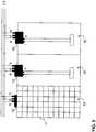
- FIGS. 2 and 3provide schematic illustrations of a photovoltaic (PV) energy supply arrangement comprising a plurality of photovoltaic modules 10 and a DC voltage bus 2.
- the control network 3is integrated in the DC voltage bus 2 (see FIG. 3 ).
- Photovoltaic modules 10each comprise a plurality of solar cells 11 and are connected to the DC voltage bus 2 using connecting devices 12. Photovoltaic modules 10 are connected to the DC voltage bus 2 such that the modules are arranged in parallel.
- each PV module 10is provided with a connecting device 12.
- a connecting device 12comprises first and second contacts I, II for connecting to a PV module and third and fourth contacts III, IV for connecting the PV modules to the DC voltage bus 2 such that mutual PV modules 10 are electrically connected in parallel.
- a contact Vis used for connecting to the control network 3.
- a PV module 10generates a DC voltage (typically between 0-100 V, e.g. between 20-80 V) in response to radiation received by the solar cells 11.
- the connecting device 12boosts the voltage to the DC voltage of the DC voltage bus 2, e.g. to 400 Vdc as will be explained in further detail with reference to FIGS. 4-7 .
- Connecting device 12may be a separate module that can be attached to a PV module 10, but may also be integrated in the PV module 10.
- the DC voltage bus 2 for the modules 10 to release the generated DC photovoltaic energyobviates the need for a DC/AC converter for each module 10 if an AC voltage is to be supplied.
- a single DC/AC converter 13, e.g. the large system inverter, the island inverter or the dual bridge inverter of FIG. 1may be connected to the DC voltage bus 2 in order to convert 400Vdc to 230Vac of the mains grid.
- the DC parallel voltage bus 2reduces the amount of cabling typically required for prior art series connected photovoltaic modules.
- the connecting device 12is employed for connecting PV module 10 to the DC voltage bus 2 in parallel with another PV module 10. Connecting device 12 is also used, amongst other functions, for boosting the voltage of the PV module 10 to a suitable voltage for the parallel voltage bus 2.
- PV module 10generates e.g. a DC voltage of 24 V that should be boosted to 400 Vdc. High voltages typically enable lower currents and, therefore, lower losses.
- PV module 10is connected to connecting device 12 using contacts I and II.
- a transformer 20is provided for EMC shielding purposes.
- the DC voltageis increased using a first capacitor C1 and a second capacitor C2 connected in parallel using an inductive coil H and a diode D.
- a switchhere a field effect transistor FET, is provided to pump charge from the first capacitor C1 to the second capacitor C2 to obtain the DC voltage required for the voltage bus 2 using contacts III and IV. Switching is performed under the control of a microprocessor uC.
- Microprocessor uCmonitors the input voltage Vin and the input current Iin for power point tracker functionality. Microprocessor uC also monitors output voltage Vout and output current Iout for monitoring output power and for security purposes. Microprocessor uC also monitors the DC voltage of the DC voltage bus 2, Vdcbus in order to control the switching of switch S. If the voltage of the bus 2 is 400Vdc, no further energy is supplied as determined by preset voltage levels in the microprocessor uC.
- the connecting device 12operates using a local power supply unit, designated local PSU, that is connected via contacts IV and V forming communication network 3. Local PSU only powers the connecting device 12 if it receives an appropriated voltage over contacts IV, V, e.g. -48V. Otherwise, switch S is open and no energy is supplied to voltage bus 2.
- local PSUlocal power supply unit
- the voltage boost efficiency that can be obtained with the embodiment of the connecting device of FIG. 4is about 80%.
- a further efficiency gaincan be obtained by using the electric circuit of FIG. 5 using a split coil transformer arrangement instead of the integral coil H of FIG. 4 .
- the coils "Coil 1" and “Coil 2"may be flat core coils comprising a planar ferrite core separated by a capacitor C3.
- the planar componentsallow integration of the components behind the PV modules 2.
- a switchis again provided to pump charge from capacitor C1 to capacitor C2 and can be controlled using a processing device uC (not shown in FIG. 5 , see FIG. 4 .)
- the current path between Coil 1 and capacitor C2 via diodes D2, D3allows remaining energy to flow to the capacitor C2 in the open state of the switch.
- the control of the switchcan be used to further boost the efficiency, e.g. by operating the switch with a combined frequency and pulse-width modulation switch scheme.
- a typical switching frequencyvaries between 20-70 kHz.
- the microprocessormay further perform the same monitoring functions as discussed with reference to FIG. 4 .
- the voltage boost efficiency that can be obtained with the planar ferrite core split coil transformeris about 97 % at 180W.
- Microcontroller uCmay comprise a power point tracker by measuring Vin and Iin for the PV module 10 to monitor whether the obtained power is within the optimum range to obtain the optimum photovoltaic conversion efficiency.
- sparkscan be formed in the photovoltaic modules 12, particularly at the contacts I, II and III, IV in case of e.g. bad contact. Sparks may lead to hotspots and subsequently may lead to fire.
- the temperaturee.g. of the first and second contacts I, II of the connecting device
- the spark detectoris provided within each connecting device 12.
- the spark detectorcomprises a circuit that is configured for detecting sparks in the main current loop of a single PV module 10.
- This measurementcan be communicated to an external control system (e.g. the energy management system in FIG. 1 or another monitoring system) and an individual photovoltaic module 10 or connection device 12 may be preventively disabled to avoid fire.
- the instruction to disable the photovoltaic module 10may originate internally, e.g. from the microprocessor, of externally, e.g. from the monitoring system.
- the disablement of the photovoltaic module 10is only marginally harmful for the total efficiency of the string comprising the disabled photovoltaic module 10 as a result of the parallel connection to the DC voltage bus 2.
- the measurements and other datamay be transmitted wirelessly for each photovoltaic module 10 to an external system (a central gateway), using e.g. ZigBee.
- Clusters of PV modules 10/connecting devices 12may communicate with a particular central gateway.
- the connection devices 12may comprise a wireless transceiver for transmitting data and receiving commands from the external system.
- Photovoltaic modules 10 and/or connecting devices 12 of these modules 10may also communicate with each other by building short range mesh networks. The performance of a single PV module 10 can be monitored and, if need be, being serviced.
- the microcontroller uC, measurement circuitry, the spark detector and/or the wireless transmitter or transceivermay also be part of the connecting device 12 of FIG. 5 .
- the microcontroller uC, measurement circuitry, the spark detector and/or the wireless transmitter or transceivermay be provided on a printed circuit board in the connecting device 12.
- FIG. 6shows a block diagram of a PV module 10 and a connecting device 12, wherein connecting device 12 provides multiple contacts I, II for batches of solar cells 11 in parallel.
- Each batchcomprises 10-15 solar cells 11 to provide a DC voltage of 7-14 Vdc.
- This DC voltageis boosted to 400 Vdc for each batch separately using the split coil transformer arrangement of FIG. 5 .
- itis no longer required to provide a by-pass with a diode as is regularly observed in prior art PV modules, indicated by the cross through the diode in FIG. 6 .
- conversion efficiencyis increased and a potential source of defects and fire is omitted.
- the microprocessorcontrols a switch S determining whether the boosted DC voltage of 400 V is supplied to the contacts III, IV and thus to the voltage bus 2.
- the connecting device 12is powered via contacts IV and V from e.g. the DC/AC converter connected to the DC voltage bus 2 as illustrated in FIG. 7 for an integral PV module 10.
- contact IVis at a potential of -48V and contact V at a potential around 0V (thus, if the DC voltage bus should be at 400V, contact III is at a potential of 352 V).
- Switch Sis open by default if no voltage is applied to contacts IV and V for the connecting device 12.
- the power for the local power supplyis obtained from the DC/AC converter 13 as illustrated in FIG. 7 via the DC voltage bus 2, more particularly the lines related control network 3.
- This control networkcan also be used for communication and security (e.g. UOVP: under-and-over voltage protection).
- UOVPunder-and-over voltage protection
- the DC voltagecan be modulated.
- contact Vmay also be used as a security contact, e.g. last make, first break, to disable the connecting device 12 until contacts III, IV are securely connected.
- Contact Vmay be a separate pin within e.g. contact III or IV.
- FIGS. 8A and 8Billustrate operating diagrams for the PV module 10/connecting device 12 and the inverter 13, respectively.
- the DC voltage of the DC voltage bus 2amounts to 400 Vdc, the maximum voltage is reached and energy is available for energy demanding arrangements. This state of the DC voltage bus is sensed by the energy demanding arrangements. These energy demanding arrangements may comprise a microprocessor to sense this state and to control a switch for connecting to the DC voltage bus 2 for receiving the DC voltage.
- the energy supplying arrangementssense that no further power is required for the bus, such that microcontroller uC of e.g. FIG.
- both energy supply arrangements and energy demand arrangementsmay supply energy to, respectively, draw energy from the DC voltage bus 2 as signalled by the DC voltage state of the DC voltage bus 2 as sensed by these arrangements.
- the DC voltage of the bus 2is 360V, the load of bus 2 is maximum and energy demand arrangements sense that power can no longer be drawn from DC voltage bus 2.
- the AC/DC double bridge converter of FIG. 1may be used to obtain a DC voltage at the DC voltage bus 2 from the AC mains grid 4.
- the DC/AC conversion of converter 13is designed to be maximum at 380V.
- the convertermay also be designed to have maximum conversion over the entire range of 360-400V.
Landscapes
- Engineering & Computer Science (AREA)
- Power Engineering (AREA)
- Direct Current Feeding And Distribution (AREA)
- Photovoltaic Devices (AREA)
Description
- The invention relates to the field of photovoltaic modules, such as solar cell modules. More particularly, the invention relates to efficient harvesting of photovoltaic energy and for efficiently providing this energy to energy demanding devices, especially in a local environment.
- In recent years, a solar cell directly converting solar energy to electric energy has increasingly been expected to serve as a next-generation energy source in particular from a viewpoint of global environmental issues. Among various types of solar cells, such as a solar cell using a compound semiconductor or an organic material, a solar cell using silicon crystal is mainly employed these days. However, other material compositions have been investigated and may proof to be advantageously employed in the future.
DE 40 32 569 discloses a photovoltaic system comprising a solar generator with a number of modules connected in series in a string, wherein multiple strings may be arranged in parallel. A DC/AC converter is provided within each module allowing the obtained DC voltage to be converted into an AC feed voltage for a mains network. The photovoltaic system is coupled to the mains network via a central monitoring and control device receiving the data from the individual modules via a common data bus.- The prior art photovoltaic system is disadvantageous in that the least efficient module (e.g. due to temporary shading of the module) in the series arrangement determines the efficiency of a complete string of modules. Moreover, each module has to be provided with a DC/AC converter.
US 2005/121067 A1 discloses a solar cell assembly including a plurality of solar cells formed on a common substrate and a DC/DC converter which converts the output from the solar cells to constitute a solar power generation apparatus. The output from the solar power generation apparatus is converted into an AC power by an inverter and supplied to a load or commercial AC power system.US 2008/097655 A1 discloses a method and system for providing a distributed local energy production system with high-voltage DC bus. In one embodiment, a system comprises a management unit to be interconnected via a network bus to a set of link modules, each link module coupled to a separate local energy production unit, each link module to include a Maximum Power Point Tracking (MPPT) step-up converter and a parameter monitoring unit to produce parameter data for the respective local energy production unit, and the local energy production units to be coupled to a high voltage power line to deliver produced electrical energy to a consumer of the energy; and the management unit to receive measured parameters from the link modules, and to send control signals to link modules to provide individual operational control of the local energy production units, the management unit to be coupled to one or more separate computers to provide the computers with access to the parameter data and control of the local energy production units.JP 2004 055603 A JP 2000 174317 A - It is an object of the present invention to provide a photovoltaic arrangement of improved efficiency.
- An arrangement comprising at least a first photovoltaic module and a second photovoltaic module in a string is disclosed. The first photovoltaic module and second photovoltaic module are electrically connected in parallel and arranged to provide a DC voltage to a voltage bus.
- Also, an electrical connecting device configured for connecting to a photovoltaic module is disclosed. The electrical connecting device comprises first and second contacts for receiving a first DC voltage from the photovoltaic module and third and fourth contacts configured for a connection to a DC voltage bus for providing a second DC voltage, dependent on the first DC voltage, to the DC voltage bus.
- Moreover, a method of installing a photovoltaic arrangement comprising at least a first and a second photovoltaic module and a DC voltage bus is disclosed. The first and second photovoltaic modules are electrically connected in parallel to the DC voltage bus.
- By providing the first and second photovoltaic module in parallel within a string of photovoltaic modules, a reduced efficiency of one or both of these parallel connected photovoltaic modules has less influence on the total efficiency of the complete string of photovoltaic modules as compared to a string wherein all photovoltaic modules are electrically connected in series. Such parallel connection is easily obtained using the connecting device. Moreover, the DC voltage parallel bus for the modules to release the generated DC photovoltaic energy obviates the need for a DC/AC converter for each module. From the perspective of installing the arrangement, the DC voltage bus reduces the amount of cabling typically required for prior art series connected photovoltaic modules. DC voltages are simple and efficient in operation as compared to AC voltages.
- The embodiment of claim 7 provides the advantage that only a single inverter is required to convert the DC voltage of the voltage bus to an AC voltage for an AC mains grid.
- The invention as defined in
claims - The embodiments of the invention as defined in
claims 8 and 2 provide an efficient means for boosting the first DC voltage (e.g. 0-100V, particularly 20-80 V) provided by each of the photovoltaic modules to a second DC voltage (e.g. 400 V) for the DC voltage bus. The efficiency gain is of the order of 2-5%. The switched-coil arrangement of the transformer, sometimes also referred to as switched auto-transformer arrangement, provides for reduced inductive leakage and thus considerably boosts the efficiency of the DC-DC voltage conversion. In particular, the coils may be flat coils comprising a planar ferrite core. The switch may be a (MOS)FET or a IGBT for further reducing losses. The control of the switch can be used to further boost the efficiency, e.g. by operating the switch with a combined frequency and pulse-width modulation switch scheme. - The embodiments of
claims 9 and 3 provide a means for determining whether or not power can be supplied to the DC voltage bus using the measured momentary DC voltage of the voltage bus.Claims - Several functions can be implemented in the connecting devices, such as defined in the embodiments of
claims 11 and 5. - The power point tracker monitors that the voltage and current supplied by the photovoltaic module is within the optimum range to obtain the optimum photovoltaic conversion efficiency.
- Sparks can be formed in the photovoltaic modules, particularly in the contacts in case of e.g. bad contact. Sparks may lead to hotspots and subsequently may lead to fire. By measuring the temperature (e.g. of the first and second contacts of the connecting device) and/or other characteristics and communicating this measurement to an external control system, an individual photovoltaic module or connection device may be preventively disabled to avoid fire. The disablement of the photovoltaic module is only marginally harmful for the total efficiency of the string comprising the disabled photovoltaic module as a result of the parallel connection to the DC voltage bus.
- The measurements and other data may be reported wirelessly for each photovoltaic module to an external system, using e.g. ZigBee. The connection devices may comprise a wireless transceiver for transmitting data and receiving commands from the external system. Photovoltaic modules and/or connecting devices of these modules may also communicate with each other by building short range mesh networks.
- The embodiment of
claim 12 rests on the insight that a considerable amount of (household) appliances are capable of operating using a DC voltage input (e.g. those comprising a switch mode power supply) and that, accordingly, a DC-AC converter is not required by directly connecting appliance to the DC voltage bus. - Hereinafter, embodiments of the invention will be described in further detail. It should be appreciated, however, that these embodiments may not be construed as limiting the scope of protection for the present invention.
- In the drawings:
FIG. 1 is a schematic illustration of a system of energy supply arrangements and energy demand arrangements connected to a DC voltage bus;FIG. 2 is a schematic illustration of an sustainable energy supplier ofFIG. 1 comprising a photovoltaic arrangement of photovoltaic modules connected to a DC voltage bus;FIG. 3 is a schematic illustration of photovoltaic modules and connecting devices for connecting the modules to the DC voltage bus;FIGS. 4-6 illustrate various embodiments of parts of electric circuits for increasing the DC voltage of the photovoltaic module;FIG. 7 provides a schematic example of connecting a photovoltaic module to a DC voltage bus comprising a DC/AC converter; andFIGS. 8A and 8B provide operation diagrams of a photovoltaic module and a DC/AC converter of the system ofFIG. 1 .FIG. 1 is a schematic illustration of anelectricity grid system 1 comprising a plurality of energy supply arrangements (devices) or sources and energy demand arrangements (devices) and aDC voltage bus 2 to which the energy supply arrangements and energy demand arrangements are connected. Furthermore, thesystem 1 comprises acontrol network 3 connected to the energy supply arrangements and energy demand arrangements as well.Control network 3 may be a power connection.Control network 3 may be separate or be integrated in theDC voltage bus 2 and is used for providing power to and/or for communication with the energy supply and energy demand arrangements as will be explained in further detail below.- Energy supply arrangements preferably comprise sustainable energy supply arrangements, including photovoltaic arrangements, wind energy arrangements and/or fuel cell arrangements. The present application primarily focuses on the photovoltaic supply arrangements comprising one or more solar cell modules.
- Energy demand arrangements include devices that may operate on a DC voltage input of the DC voltage bus, including computers, light sources, televisions etc. Generally, devices comprising a switched mode power supply are capable of operating with a DC voltage. Operation of devices at DC voltages saves power, while particular components (e.g. capacitors) can be saved or have an increased life time.
- Other devices that operate on the DC voltage of the DC voltage bus include an energy management system, a large inverter system, an island inverter system (for stand alone AC power supply, typically used for providing AC power locally) and a double active DC/AC bridge. The energy management system is configured for managing at least one of the energy supply and demand arrangements either via the
control network 3 or wirelessly. In particular, the energy management system may be used to overrule decisions made internally by the energy supply or demand arrangements, e.g. with regard to whether an arrangement may supply and/or demand energy from the voltage bus. The inverters are used for converting the DC voltage to an AC voltage for anAC mains grid 4. The double active bridge may also convert AC voltage of the AC mains grid to the DC voltage bus as a backup in case energy suppliers are not capable of supplying sufficient power to the DC bus. - However, the
electricity grid system 1 also comprises energy supply arrangements configured for temporarily storing electric energy and for releasing the energy at a later stage for the energy demand arrangements. InFIG. 1 , these energy supply arrangements include a super capacitor and a battery. The super capacitor may be used for supplying instantaneous peak energy demands from an energy demand arrangement during a limited period of time. - The
DC voltage bus 2 of theelectricity grid system 1 is capable of assuming a plurality of DC voltage states. The energy supply arrangements and energy demand arrangements are configured for sensing the DC voltage state of theDC voltage bus 2 and to adapt the energy supply, respectively, the energy demand to the sensed DC voltage state. This sensing is particularly advantageous for sustainable energy supply arrangements as such arrangements are characterized by unpredictable behaviour. The DC voltage state of theDC voltage bus 2 is directly visible for both the energy supply arrangements and the DC demand arrangements. The decision to supply or demand energy from the DC voltage bus may be overruled by the energy management system as illustrated inFIG. 1 . - As an example, an energy supply arrangement may comprise a microprocessor connected such that the DC voltage of the DC voltage bus can be detected and compare the detected voltage with pre-set voltage levels. As an example, energy may be supplied if the DC voltage of the
DC voltage bus 2 is detected to be between a maximum DC voltage of e.g. 400 Vdc and a minimum DC voltage of e.g. 360 Vdc. As another example, an energy demanding arrangement may be configured not to demand energy from theDC voltage bus 2 if the detected DC voltage is below a minimum DC voltage of e.g. 360 Vdc. As yet another example, an energy supply arrangement configured for storing and releasing energy may be programmed to release energy as soon as the DC voltage of thevoltage bus 2 is below a particular threshold. None of the energy supply arrangements and energy demand arrangement requires a dedicated inverter dependent on the type of supply or demand arrangement. - Also, if the energy demand arrangements have an energy surplus, this energy can be provided back to the
DC voltage bus 2. Of course, such energy demand arrangements must be configured for sensing the DC voltage state of theDC voltage bus 2 and for supply the energy surplus to the DC voltage bus in dependence of the sensed DC voltage state as described above for an energy supply arrangement. This is generally not possible for an AC mains grid due to very strict requirements and complicated electronics for energy feedback to such an AC mains grid. - The
DC voltage bus 2 may transport a power of 4-8 kW for a string of PV modules 10 (seeFIG. 2 ). Such a voltage bus is particularly useful in a local environment, such as houses, ships, offices, etc. Use of the AC mains grid can be minimized if such aDC voltage bus 2 is provided. FIGS. 2 and3 provide schematic illustrations of a photovoltaic (PV) energy supply arrangement comprising a plurality ofphotovoltaic modules 10 and aDC voltage bus 2. Thecontrol network 3 is integrated in the DC voltage bus 2 (seeFIG. 3 ).Photovoltaic modules 10 each comprise a plurality ofsolar cells 11 and are connected to theDC voltage bus 2 using connectingdevices 12.Photovoltaic modules 10 are connected to theDC voltage bus 2 such that the modules are arranged in parallel. By providing thephotovoltaic modules 10 in parallel within a string of photovoltaic modules, a reduced efficiency of one of these parallel connectedphotovoltaic modules 10 has less influence on the total efficiency of the complete string of photovoltaic modules as compared to a prior art arrangement wherein all photovoltaic modules in a string are connected in series.- In particular, each
PV module 10 is provided with a connectingdevice 12. A connectingdevice 12 comprises first and second contacts I, II for connecting to a PV module and third and fourth contacts III, IV for connecting the PV modules to theDC voltage bus 2 such thatmutual PV modules 10 are electrically connected in parallel. A contact V is used for connecting to thecontrol network 3. - Generally, a
PV module 10 generates a DC voltage (typically between 0-100 V, e.g. between 20-80 V) in response to radiation received by thesolar cells 11. The connectingdevice 12 boosts the voltage to the DC voltage of theDC voltage bus 2, e.g. to 400 Vdc as will be explained in further detail with reference toFIGS. 4-7 . - Connecting
device 12 may be a separate module that can be attached to aPV module 10, but may also be integrated in thePV module 10. - The
DC voltage bus 2 for themodules 10 to release the generated DC photovoltaic energy obviates the need for a DC/AC converter for eachmodule 10 if an AC voltage is to be supplied. A single DC/AC converter 13, e.g. the large system inverter, the island inverter or the dual bridge inverter ofFIG. 1 , may be connected to theDC voltage bus 2 in order to convert 400Vdc to 230Vac of the mains grid. The DCparallel voltage bus 2 reduces the amount of cabling typically required for prior art series connected photovoltaic modules. - The connecting
device 12 is employed for connectingPV module 10 to theDC voltage bus 2 in parallel with anotherPV module 10. Connectingdevice 12 is also used, amongst other functions, for boosting the voltage of thePV module 10 to a suitable voltage for theparallel voltage bus 2. - In
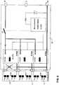
FIG. 4 ,PV module 10 generates e.g. a DC voltage of 24 V that should be boosted to 400 Vdc. High voltages typically enable lower currents and, therefore, lower losses. PV module 10 is connected to connectingdevice 12 using contacts I and II. Atransformer 20 is provided for EMC shielding purposes. The DC voltage is increased using a first capacitor C1 and a second capacitor C2 connected in parallel using an inductive coil H and a diode D. A switch, here a field effect transistor FET, is provided to pump charge from the first capacitor C1 to the second capacitor C2 to obtain the DC voltage required for thevoltage bus 2 using contacts III and IV. Switching is performed under the control of a microprocessor uC.- Microprocessor uC monitors the input voltage Vin and the input current Iin for power point tracker functionality. Microprocessor uC also monitors output voltage Vout and output current Iout for monitoring output power and for security purposes. Microprocessor uC also monitors the DC voltage of the
DC voltage bus 2, Vdcbus in order to control the switching of switch S. If the voltage of thebus 2 is 400Vdc, no further energy is supplied as determined by preset voltage levels in the microprocessor uC. The connectingdevice 12 operates using a local power supply unit, designated local PSU, that is connected via contacts IV and V formingcommunication network 3. Local PSU only powers the connectingdevice 12 if it receives an appropriated voltage over contacts IV, V, e.g. -48V. Otherwise, switch S is open and no energy is supplied tovoltage bus 2. - The voltage boost efficiency that can be obtained with the embodiment of the connecting device of
FIG. 4 is about 80%. - A further efficiency gain can be obtained by using the electric circuit of
FIG. 5 using a split coil transformer arrangement instead of the integral coil H ofFIG. 4 . The coils "Coil 1" and "Coil 2" may be flat core coils comprising a planar ferrite core separated by a capacitor C3. The planar components allow integration of the components behind thePV modules 2. A switch is again provided to pump charge from capacitor C1 to capacitor C2 and can be controlled using a processing device uC (not shown inFIG. 5 , seeFIG. 4 .) The current path betweenCoil 1 and capacitor C2 via diodes D2, D3 allows remaining energy to flow to the capacitor C2 in the open state of the switch. The control of the switch can be used to further boost the efficiency, e.g. by operating the switch with a combined frequency and pulse-width modulation switch scheme. A typical switching frequency varies between 20-70 kHz. The microprocessor may further perform the same monitoring functions as discussed with reference toFIG. 4 . - The voltage boost efficiency that can be obtained with the planar ferrite core split coil transformer is about 97 % at 180W.
- It is noted that other methods for increasing the DC voltage of the
PV modules 10 may be used. As an example, a switched capacitor arrangement may be employed. However, such an arrangement generally requires further measures to be taken for controlling the output voltage and the life expectancy of the capacitors at the relevant power is generally too low. - Several further functions can be implemented in the connecting
devices 12 ofFIGS. 4 and 5 . Of course, such functions require power and may decrease the efficiency of the PV module/connectingdevice 12 combination. - Microcontroller uC may comprise a power point tracker by measuring Vin and Iin for the
PV module 10 to monitor whether the obtained power is within the optimum range to obtain the optimum photovoltaic conversion efficiency. - Furthermore, sparks can be formed in the
photovoltaic modules 12, particularly at the contacts I, II and III, IV in case of e.g. bad contact. Sparks may lead to hotspots and subsequently may lead to fire. The temperature (e.g. of the first and second contacts I, II of the connecting device) and/or other characteristics can be measured using a spark detector in combination with microcontroller uC as depicted inFIG. 4 . The spark detector is provided within each connectingdevice 12. The spark detector comprises a circuit that is configured for detecting sparks in the main current loop of asingle PV module 10. - This measurement can be communicated to an external control system (e.g. the energy management system in
FIG. 1 or another monitoring system) and an individualphotovoltaic module 10 orconnection device 12 may be preventively disabled to avoid fire. The instruction to disable thephotovoltaic module 10 may originate internally, e.g. from the microprocessor, of externally, e.g. from the monitoring system. The disablement of thephotovoltaic module 10 is only marginally harmful for the total efficiency of the string comprising the disabledphotovoltaic module 10 as a result of the parallel connection to theDC voltage bus 2. - The measurements and other data (current, voltage, power, status) may be transmitted wirelessly for each
photovoltaic module 10 to an external system (a central gateway), using e.g. ZigBee. Clusters ofPV modules 10/connectingdevices 12 may communicate with a particular central gateway. Theconnection devices 12 may comprise a wireless transceiver for transmitting data and receiving commands from the external system.Photovoltaic modules 10 and/or connectingdevices 12 of thesemodules 10 may also communicate with each other by building short range mesh networks. The performance of asingle PV module 10 can be monitored and, if need be, being serviced. - The microcontroller uC, measurement circuitry, the spark detector and/or the wireless transmitter or transceiver may also be part of the connecting
device 12 ofFIG. 5 . - The microcontroller uC, measurement circuitry, the spark detector and/or the wireless transmitter or transceiver may be provided on a printed circuit board in the connecting
device 12. - It should be noted that instead of a microcontroller, other controllers can be used.
FIG. 6 shows a block diagram of aPV module 10 and a connectingdevice 12, wherein connectingdevice 12 provides multiple contacts I, II for batches ofsolar cells 11 in parallel. Each batch comprises 10-15solar cells 11 to provide a DC voltage of 7-14 Vdc. This DC voltage is boosted to 400 Vdc for each batch separately using the split coil transformer arrangement ofFIG. 5 . As a consequence, it is no longer required to provide a by-pass with a diode as is regularly observed in prior art PV modules, indicated by the cross through the diode inFIG. 6 . By avoiding the need of a by-pass diode, conversion efficiency is increased and a potential source of defects and fire is omitted.- The microprocessor controls a switch S determining whether the boosted DC voltage of 400 V is supplied to the contacts III, IV and thus to the
voltage bus 2. The connectingdevice 12 is powered via contacts IV and V from e.g. the DC/AC converter connected to theDC voltage bus 2 as illustrated inFIG. 7 for anintegral PV module 10. As an example, contact IV is at a potential of -48V and contact V at a potential around 0V (thus, if the DC voltage bus should be at 400V, contact III is at a potential of 352 V). Switch S is open by default if no voltage is applied to contacts IV and V for the connectingdevice 12. - The power for the local power supply is obtained from the DC/
AC converter 13 as illustrated inFIG. 7 via theDC voltage bus 2, more particularly the lines relatedcontrol network 3. This control network can also be used for communication and security (e.g. UOVP: under-and-over voltage protection). For communication (e.g. Ethernet) between the connectingmodule 12 and an inverter, the DC voltage can be modulated. Also, contact V may also be used as a security contact, e.g. last make, first break, to disable the connectingdevice 12 until contacts III, IV are securely connected. Contact V may be a separate pin within e.g. contact III or IV. FIGS. 8A and 8B illustrate operating diagrams for thePV module 10/connectingdevice 12 and theinverter 13, respectively. If the DC voltage of theDC voltage bus 2 amounts to 400 Vdc, the maximum voltage is reached and energy is available for energy demanding arrangements. This state of the DC voltage bus is sensed by the energy demanding arrangements. These energy demanding arrangements may comprise a microprocessor to sense this state and to control a switch for connecting to theDC voltage bus 2 for receiving the DC voltage. On the other hand, if the DC voltage bus is 400V, the energy supplying arrangements sense that no further power is required for the bus, such that microcontroller uC of e.g.FIG. 6 opens switch S and energy is no longer supplied to theDC voltage bus 2 from the PV module 10 (provided that the super capacitor and battery are also full). If the voltage on theDC voltage bus 2 is 380 V, both energy supply arrangements and energy demand arrangements may supply energy to, respectively, draw energy from theDC voltage bus 2 as signalled by the DC voltage state of theDC voltage bus 2 as sensed by these arrangements. If the DC voltage of thebus 2 is 360V, the load ofbus 2 is maximum and energy demand arrangements sense that power can no longer be drawn fromDC voltage bus 2. If power is needed, the AC/DC double bridge converter ofFIG. 1 may be used to obtain a DC voltage at theDC voltage bus 2 from theAC mains grid 4.- As can be observed from
FIG. 8B , the DC/AC conversion ofconverter 13 is designed to be maximum at 380V. Of course, the converter may also be designed to have maximum conversion over the entire range of 360-400V.
Claims (14)
- An electrical connecting device (12) configured for connecting to a photovoltaic module (10), the electrical connecting device comprising first (I) and second (II) contacts for receiving a first DC voltage from said photovoltaic module and third (III) and fourth (IV) contacts configured for electrical connection to a DC voltage bus (2) for providing a second DC voltage, dependent on said first DC voltage, to said DC voltage bus,
wherein said electrical connecting device is configured for parallel electrical connection of said photovoltaic module with respect to another photovoltaic module through the third and fourth contacts to said DC voltage bus,
characterized in that:said electrical connecting device comprises a fifth contact (V) to a control network (3);said electrical connecting device comprises a switch (S) for the third contact (III) and a power supply unit (local PSU) connected to the control network (3) via the fourth contact (IV) and the fifth contact (V);the power supply unit is configured to power the electrical connecting device if a pre-determined voltage is supplied across the fourth contact and the fifth contact, otherwise the switch (S) is open and no DC voltage is supplied to the DC voltage bus (2) from the electrical connecting device (12). - The electrical connecting device according to claim 1, further comprising a DC step-up voltage converter for converting said first DC voltage to said second DC voltage, said second DC voltage being higher than said first DC voltage.
- The electrical connecting device according to claim 1 or 2, wherein said connecting device comprises a sensor, e.g. a microprocessor comprising sensing software, configured for sensing a DC voltage state of said voltage bus and for supplying said second DC voltage to said voltage bus in dependence of said DC voltage state.
- The electrical connecting device according to claim 3, wherein said voltage bus is configured for operating in a DC voltage state range of 360-400 V and wherein said sensor is configured for supplying said DC voltage only when said sensed DC voltage is within said DC voltage state range.
- The electrical connecting device according to one or more of the claims 1-4, wherein said connecting device comprises at least one of:- a power point tracker for tracking an optimal operation point of said photovoltaic module;- a spark detector; and- a wireless radiofrequency communication module.
- An arrangement comprising:at least a first photovoltaic module (10) anda second photovoltaic module (10) in a string,wherein said first photovoltaic module and second photovoltaic module are electrically connected in parallel and arranged to provide a DC voltage to a DC voltage bus (2), andwherein said first photovoltaic module is connected to the DC voltage bus through a first connecting device according to any of claims 1-5, and said second photovoltaic module is connected to the DC voltage bus through a second connecting device according to any of claims 1-5.
- The arrangement according to claim 6, further comprising a DC/AC converter connected to said voltage bus (2) for receiving said DC voltage of said first and second photovoltaic module and for converting said DC voltage to an AC voltage.
- The arrangement according to claim 6 or 7, wherein at least one of said first and second connecting device (12) comprises a DC step-up voltage converter configured to provide said DC voltage to said voltage bus (2).
- The arrangement according to claim 6, 7 or 8, wherein at least one of said first and second connecting device comprises a sensor, e.g. a microprocessor comprising sensing software, configured for sensing a DC voltage state of said voltage bus and for supplying said DC voltage to said voltage bus in dependence of said DC voltage state.
- The arrangement according to claim 9, wherein said voltage bus is configured for operating in a DC voltage state range of 360-400 V and wherein said sensor is configured for supplying said DC voltage only when said sensed DC voltage is within said DC voltage state range.
- The arrangement according to any of claims 6-10, wherein at least one of said first and second connecting device comprises at least one of:- a power point tracker for tracking an optimal operation point of said first and/or second photovoltaic module;- a spark detector; and- a wireless radiofrequency communication module.
- The arrangement according to any of claims 6-11, wherein said voltage bus is electrically connected to at least one energy demanding device for providing said DC voltage to said energy demanding device.
- A method of installing a photovoltaic arrangement comprising at least a first and a second photovoltaic module (10) and a DC voltage bus (2), the method comprising:- electrically connecting said first photovoltaic module in parallel to said voltage bus through a first connecting device according to any of claims 1-5; and- electrically connecting said second photovoltaic module in parallel to said voltage bus through a second connecting device according to any of claims 1-5.
- The method according to claim 13, wherein said arrangement further comprises a first and a second connecting device, the method comprising:- connecting the first contact and the second contact of said first connecting device to said first photovoltaic module to obtain a first DC voltage from said first photovoltaic module, and- electrically connecting the third contact and the fourth contact of said first connecting device in parallel to said DC voltage bus to provide a second DC voltage to said DC voltage bus; and- repeating these steps for the second connecting device.
Applications Claiming Priority (1)
| Application Number | Priority Date | Filing Date | Title |
|---|---|---|---|
| NL2001920 | 2008-08-26 |
Publications (4)
| Publication Number | Publication Date |
|---|---|
| EP2159895A2 EP2159895A2 (en) | 2010-03-03 |
| EP2159895A3 EP2159895A3 (en) | 2014-01-22 |
| EP2159895B1true EP2159895B1 (en) | 2021-04-21 |
| EP2159895B8 EP2159895B8 (en) | 2021-06-23 |
Family
ID=41372785
Family Applications (3)
| Application Number | Title | Priority Date | Filing Date |
|---|---|---|---|
| EP09150715.2AActiveEP2159896B1 (en) | 2008-08-26 | 2009-01-16 | Electrical system and method of operating such a system |
| EP20198711.2AActiveEP3796504B1 (en) | 2008-08-26 | 2009-01-16 | Electrical system and method of operating such a system |
| EP09150712.9AActiveEP2159895B8 (en) | 2008-08-26 | 2009-01-16 | Electrically parallel connection of photovoltaic modules in a string to provide a DC voltage to a DC voltage bus |
Family Applications Before (2)
| Application Number | Title | Priority Date | Filing Date |
|---|---|---|---|
| EP09150715.2AActiveEP2159896B1 (en) | 2008-08-26 | 2009-01-16 | Electrical system and method of operating such a system |
| EP20198711.2AActiveEP3796504B1 (en) | 2008-08-26 | 2009-01-16 | Electrical system and method of operating such a system |
Country Status (1)
| Country | Link |
|---|---|
| EP (3) | EP2159896B1 (en) |
Families Citing this family (6)
| Publication number | Priority date | Publication date | Assignee | Title |
|---|---|---|---|---|
| CN101951014A (en) | 2010-10-29 | 2011-01-19 | 上海致远绿色能源有限公司 | Wind-light-diesel commercial power integral power supply system |
| JP5951269B2 (en)* | 2012-01-30 | 2016-07-13 | 株式会社東芝 | PV panel diagnostic apparatus, diagnostic method, and diagnostic program |
| CN104980091A (en)* | 2015-06-23 | 2015-10-14 | 四川蜀旺科技有限公司 | Luminous energy storage inversion system |
| EP3611832A1 (en)* | 2018-08-13 | 2020-02-19 | FRONIUS INTERNATIONAL GmbH | Photovoltaic inverter and method for operating the same |
| GB202201109D0 (en)* | 2022-01-28 | 2022-03-16 | Pulsiv Ltd | Solar panel architecture |
| CN118713139B (en)* | 2024-08-28 | 2024-12-13 | 厦门和储能源科技有限公司 | Power regulation and control method and system based on demand control and backflow prevention control |
Family Cites Families (10)
| Publication number | Priority date | Publication date | Assignee | Title |
|---|---|---|---|---|
| DE4032569A1 (en) | 1990-10-13 | 1992-04-16 | Flachglas Solartechnik Gmbh | Photovoltaic system coupled to mains network - has individual modules incorporating respective DC-AC converter for direct supply of mains network |
| JP2000174317A (en)* | 1998-12-01 | 2000-06-23 | Toshiba Corp | Solar cell power generation system |
| JP3655831B2 (en)* | 2001-02-14 | 2005-06-02 | シャープ株式会社 | Booster unit, power conditioner, and solar power generation system using them |
| US6369462B1 (en)* | 2001-05-02 | 2002-04-09 | The Aerospace Corporation | Maximum power tracking solar power system |
| DE10136147B4 (en)* | 2001-07-25 | 2004-11-04 | Kolm, Hendrik, Dipl.-Ing. | Photovoltaic alternator |
| US7612283B2 (en)* | 2002-07-09 | 2009-11-03 | Canon Kabushiki Kaisha | Solar power generation apparatus and its manufacturing method |
| JP2004055603A (en)* | 2002-07-16 | 2004-02-19 | Canon Inc | Solar cell module, solar cell array, and solar power generation system |
| US7239044B1 (en)* | 2004-12-09 | 2007-07-03 | Sandia Corporation | Enhanced distributed energy resource system |
| JP5124114B2 (en)* | 2006-08-28 | 2013-01-23 | シャープ株式会社 | Power conditioner with power storage function |
| US8751053B2 (en)* | 2006-10-19 | 2014-06-10 | Tigo Energy, Inc. | Method and system to provide a distributed local energy production system with high-voltage DC bus |
- 2009
- 2009-01-16EPEP09150715.2Apatent/EP2159896B1/enactiveActive
- 2009-01-16EPEP20198711.2Apatent/EP3796504B1/enactiveActive
- 2009-01-16EPEP09150712.9Apatent/EP2159895B8/enactiveActive
Non-Patent Citations (1)
| Title |
|---|
| None* |
Also Published As
| Publication number | Publication date |
|---|---|
| EP2159896A2 (en) | 2010-03-03 |
| EP2159895B8 (en) | 2021-06-23 |
| EP2159895A2 (en) | 2010-03-03 |
| EP3796504B1 (en) | 2023-09-13 |
| EP2159896A3 (en) | 2014-01-29 |
| EP2159895A3 (en) | 2014-01-22 |
| EP3796504A1 (en) | 2021-03-24 |
| EP2159896B1 (en) | 2020-09-30 |
Similar Documents
| Publication | Publication Date | Title |
|---|---|---|
| US8432143B2 (en) | Electrically parallel connection of photovoltaic modules in a string to provide a DC voltage to a DC voltage bus | |
| US11728645B2 (en) | Enhanced system and method for string balancing | |
| US10819117B2 (en) | Systems and methods to combine strings of solar panels | |
| KR100686281B1 (en) | Method for operating a power supply system having an inverter connected in parallel and a power conversion system | |
| CN104713176B (en) | Photovoltaic air conditioning system and control method thereof | |
| CN108306333B (en) | Circuit for interconnected DC power supplies | |
| US9287712B2 (en) | Photovoltaic power plant | |
| CN106887861B (en) | Distributed power harvesting system using DC power sources | |
| CN204119035U (en) | Produce the device that bucking voltage exports | |
| US9190847B2 (en) | Power distribution system distributing an alternating current (AC) power and a direct current (DC) power to load devices | |
| US20090179499A1 (en) | Multiple bi-directional input/output power control system | |
| KR102559055B1 (en) | System for photovoltaics | |
| EP2159895B1 (en) | Electrically parallel connection of photovoltaic modules in a string to provide a DC voltage to a DC voltage bus | |
| KR20160129265A (en) | Grid connected power apparatus using solar converter and energy storage converter | |
| KR102421893B1 (en) | Energy storage system | |
| JP5373528B2 (en) | Power distribution equipment | |
| KR20160129266A (en) | Grid connected power apparatus using solar converter, energy storage converter and wind converter | |
| JP2011078237A (en) | Power supply system | |
| KR101764651B1 (en) | Power applying apparatus and method for controlling connecting photovoltaic power generating apparatus | |
| EP4181393A1 (en) | Power supply system and power supply control method therefor | |
| US10886744B2 (en) | Power conversion system, power supply system and power conversion device | |
| CN223379081U (en) | DCDC bidirectional charge-discharge circuit and device | |
| CN102170167A (en) | Device for providing DC (direct-current) voltage for DC voltage bus through line parallel and electrical connection of photoelectric modules | |
| CN120604644A (en) | Photovoltaic module |
Legal Events
| Date | Code | Title | Description |
|---|---|---|---|
| PUAI | Public reference made under article 153(3) epc to a published international application that has entered the european phase | Free format text:ORIGINAL CODE: 0009012 | |
| AK | Designated contracting states | Kind code of ref document:A2 Designated state(s):AT BE BG CH CY CZ DE DK EE ES FI FR GB GR HR HU IE IS IT LI LT LU LV MC MK MT NL NO PL PT RO SE SI SK TR | |
| AX | Request for extension of the european patent | Extension state:AL BA RS | |
| RAP1 | Party data changed (applicant data changed or rights of an application transferred) | Owner name:FEMTOGRID ENERGY SOLUTIONS B.V. | |
| PUAL | Search report despatched | Free format text:ORIGINAL CODE: 0009013 | |
| AK | Designated contracting states | Kind code of ref document:A3 Designated state(s):AT BE BG CH CY CZ DE DK EE ES FI FR GB GR HR HU IE IS IT LI LT LU LV MC MK MT NL NO PL PT RO SE SI SK TR | |
| AX | Request for extension of the european patent | Extension state:AL BA RS | |
| RIC1 | Information provided on ipc code assigned before grant | Ipc:H01L 31/00 20060101ALI20131217BHEP Ipc:H02J 1/10 20060101AFI20131217BHEP Ipc:H02J 3/38 20060101ALI20131217BHEP | |
| 17P | Request for examination filed | Effective date:20140221 | |
| RBV | Designated contracting states (corrected) | Designated state(s):AT BE BG CH CY CZ DE DK EE ES FI FR GB GR HR HU IE IS IT LI LT LU LV MC MK MT NL NO PL PT RO SE SI SK TR | |
| AKX | Designation fees paid | Designated state(s):AT BE BG CH CY CZ DE DK EE ES FI FR GB GR HR HU IE IS IT LI LT LU LV MC MK MT NL NO PL PT RO SE SI SK TR | |
| STAA | Information on the status of an ep patent application or granted ep patent | Free format text:STATUS: EXAMINATION IS IN PROGRESS | |
| 17Q | First examination report despatched | Effective date:20200416 | |
| GRAP | Despatch of communication of intention to grant a patent | Free format text:ORIGINAL CODE: EPIDOSNIGR1 | |
| STAA | Information on the status of an ep patent application or granted ep patent | Free format text:STATUS: GRANT OF PATENT IS INTENDED | |
| INTG | Intention to grant announced | Effective date:20210118 | |
| GRAS | Grant fee paid | Free format text:ORIGINAL CODE: EPIDOSNIGR3 | |
| GRAA | (expected) grant | Free format text:ORIGINAL CODE: 0009210 | |
| STAA | Information on the status of an ep patent application or granted ep patent | Free format text:STATUS: THE PATENT HAS BEEN GRANTED | |
| AK | Designated contracting states | Kind code of ref document:B1 Designated state(s):AT BE BG CH CY CZ DE DK EE ES FI FR GB GR HR HU IE IS IT LI LT LU LV MC MK MT NL NO PL PT RO SE SI SK TR | |
| REG | Reference to a national code | Ref country code:GB Ref legal event code:FG4D | |
| REG | Reference to a national code | Ref country code:CH Ref legal event code:EP | |
| REG | Reference to a national code | Ref country code:DE Ref legal event code:R096 Ref document number:602009063595 Country of ref document:DE Ref country code:IE Ref legal event code:FG4D | |
| REG | Reference to a national code | Ref country code:AT Ref legal event code:REF Ref document number:1385650 Country of ref document:AT Kind code of ref document:T Effective date:20210515 | |
| RAP4 | Party data changed (patent owner data changed or rights of a patent transferred) | Owner name:FEMTOGRID ENERGY SOLUTIONS B.V. | |
| REG | Reference to a national code | Ref country code:CH Ref legal event code:PK Free format text:BERICHTIGUNG B8 | |
| REG | Reference to a national code | Ref country code:NL Ref legal event code:FP | |
| REG | Reference to a national code | Ref country code:SE Ref legal event code:TRGR Ref country code:LT Ref legal event code:MG9D | |
| REG | Reference to a national code | Ref country code:AT Ref legal event code:MK05 Ref document number:1385650 Country of ref document:AT Kind code of ref document:T Effective date:20210421 | |
| PG25 | Lapsed in a contracting state [announced via postgrant information from national office to epo] | Ref country code:AT Free format text:LAPSE BECAUSE OF FAILURE TO SUBMIT A TRANSLATION OF THE DESCRIPTION OR TO PAY THE FEE WITHIN THE PRESCRIBED TIME-LIMIT Effective date:20210421 Ref country code:BG Free format text:LAPSE BECAUSE OF FAILURE TO SUBMIT A TRANSLATION OF THE DESCRIPTION OR TO PAY THE FEE WITHIN THE PRESCRIBED TIME-LIMIT Effective date:20210721 Ref country code:HR Free format text:LAPSE BECAUSE OF FAILURE TO SUBMIT A TRANSLATION OF THE DESCRIPTION OR TO PAY THE FEE WITHIN THE PRESCRIBED TIME-LIMIT Effective date:20210421 Ref country code:LT Free format text:LAPSE BECAUSE OF FAILURE TO SUBMIT A TRANSLATION OF THE DESCRIPTION OR TO PAY THE FEE WITHIN THE PRESCRIBED TIME-LIMIT Effective date:20210421 Ref country code:FI Free format text:LAPSE BECAUSE OF FAILURE TO SUBMIT A TRANSLATION OF THE DESCRIPTION OR TO PAY THE FEE WITHIN THE PRESCRIBED TIME-LIMIT Effective date:20210421 | |
| PG25 | Lapsed in a contracting state [announced via postgrant information from national office to epo] | Ref country code:LV Free format text:LAPSE BECAUSE OF FAILURE TO SUBMIT A TRANSLATION OF THE DESCRIPTION OR TO PAY THE FEE WITHIN THE PRESCRIBED TIME-LIMIT Effective date:20210421 Ref country code:IS Free format text:LAPSE BECAUSE OF FAILURE TO SUBMIT A TRANSLATION OF THE DESCRIPTION OR TO PAY THE FEE WITHIN THE PRESCRIBED TIME-LIMIT Effective date:20210821 Ref country code:GR Free format text:LAPSE BECAUSE OF FAILURE TO SUBMIT A TRANSLATION OF THE DESCRIPTION OR TO PAY THE FEE WITHIN THE PRESCRIBED TIME-LIMIT Effective date:20210722 Ref country code:NO Free format text:LAPSE BECAUSE OF FAILURE TO SUBMIT A TRANSLATION OF THE DESCRIPTION OR TO PAY THE FEE WITHIN THE PRESCRIBED TIME-LIMIT Effective date:20210721 Ref country code:PL Free format text:LAPSE BECAUSE OF FAILURE TO SUBMIT A TRANSLATION OF THE DESCRIPTION OR TO PAY THE FEE WITHIN THE PRESCRIBED TIME-LIMIT Effective date:20210421 Ref country code:PT Free format text:LAPSE BECAUSE OF FAILURE TO SUBMIT A TRANSLATION OF THE DESCRIPTION OR TO PAY THE FEE WITHIN THE PRESCRIBED TIME-LIMIT Effective date:20210823 Ref country code:ES Free format text:LAPSE BECAUSE OF FAILURE TO SUBMIT A TRANSLATION OF THE DESCRIPTION OR TO PAY THE FEE WITHIN THE PRESCRIBED TIME-LIMIT Effective date:20210421 | |
| REG | Reference to a national code | Ref country code:DE Ref legal event code:R097 Ref document number:602009063595 Country of ref document:DE | |
| PG25 | Lapsed in a contracting state [announced via postgrant information from national office to epo] | Ref country code:SK Free format text:LAPSE BECAUSE OF FAILURE TO SUBMIT A TRANSLATION OF THE DESCRIPTION OR TO PAY THE FEE WITHIN THE PRESCRIBED TIME-LIMIT Effective date:20210421 Ref country code:DK Free format text:LAPSE BECAUSE OF FAILURE TO SUBMIT A TRANSLATION OF THE DESCRIPTION OR TO PAY THE FEE WITHIN THE PRESCRIBED TIME-LIMIT Effective date:20210421 Ref country code:EE Free format text:LAPSE BECAUSE OF FAILURE TO SUBMIT A TRANSLATION OF THE DESCRIPTION OR TO PAY THE FEE WITHIN THE PRESCRIBED TIME-LIMIT Effective date:20210421 Ref country code:CZ Free format text:LAPSE BECAUSE OF FAILURE TO SUBMIT A TRANSLATION OF THE DESCRIPTION OR TO PAY THE FEE WITHIN THE PRESCRIBED TIME-LIMIT Effective date:20210421 Ref country code:RO Free format text:LAPSE BECAUSE OF FAILURE TO SUBMIT A TRANSLATION OF THE DESCRIPTION OR TO PAY THE FEE WITHIN THE PRESCRIBED TIME-LIMIT Effective date:20210421 | |
| PLBE | No opposition filed within time limit | Free format text:ORIGINAL CODE: 0009261 | |
| STAA | Information on the status of an ep patent application or granted ep patent | Free format text:STATUS: NO OPPOSITION FILED WITHIN TIME LIMIT | |
| 26N | No opposition filed | Effective date:20220124 | |
| PG25 | Lapsed in a contracting state [announced via postgrant information from national office to epo] | Ref country code:IS Free format text:LAPSE BECAUSE OF FAILURE TO SUBMIT A TRANSLATION OF THE DESCRIPTION OR TO PAY THE FEE WITHIN THE PRESCRIBED TIME-LIMIT Effective date:20210821 | |
| PG25 | Lapsed in a contracting state [announced via postgrant information from national office to epo] | Ref country code:IT Free format text:LAPSE BECAUSE OF FAILURE TO SUBMIT A TRANSLATION OF THE DESCRIPTION OR TO PAY THE FEE WITHIN THE PRESCRIBED TIME-LIMIT Effective date:20210421 | |
| PG25 | Lapsed in a contracting state [announced via postgrant information from national office to epo] | Ref country code:MC Free format text:LAPSE BECAUSE OF FAILURE TO SUBMIT A TRANSLATION OF THE DESCRIPTION OR TO PAY THE FEE WITHIN THE PRESCRIBED TIME-LIMIT Effective date:20210421 | |
| REG | Reference to a national code | Ref country code:CH Ref legal event code:PL | |
| REG | Reference to a national code | Ref country code:BE Ref legal event code:MM Effective date:20220131 | |
| PG25 | Lapsed in a contracting state [announced via postgrant information from national office to epo] | Ref country code:LU Free format text:LAPSE BECAUSE OF NON-PAYMENT OF DUE FEES Effective date:20220116 | |
| PG25 | Lapsed in a contracting state [announced via postgrant information from national office to epo] | Ref country code:BE Free format text:LAPSE BECAUSE OF NON-PAYMENT OF DUE FEES Effective date:20220131 | |
| PG25 | Lapsed in a contracting state [announced via postgrant information from national office to epo] | Ref country code:LI Free format text:LAPSE BECAUSE OF NON-PAYMENT OF DUE FEES Effective date:20220131 Ref country code:CH Free format text:LAPSE BECAUSE OF NON-PAYMENT OF DUE FEES Effective date:20220131 | |
| PG25 | Lapsed in a contracting state [announced via postgrant information from national office to epo] | Ref country code:IE Free format text:LAPSE BECAUSE OF NON-PAYMENT OF DUE FEES Effective date:20220116 | |
| PG25 | Lapsed in a contracting state [announced via postgrant information from national office to epo] | Ref country code:HU Free format text:LAPSE BECAUSE OF FAILURE TO SUBMIT A TRANSLATION OF THE DESCRIPTION OR TO PAY THE FEE WITHIN THE PRESCRIBED TIME-LIMIT; INVALID AB INITIO Effective date:20090116 | |
| PG25 | Lapsed in a contracting state [announced via postgrant information from national office to epo] | Ref country code:MK Free format text:LAPSE BECAUSE OF FAILURE TO SUBMIT A TRANSLATION OF THE DESCRIPTION OR TO PAY THE FEE WITHIN THE PRESCRIBED TIME-LIMIT Effective date:20210421 Ref country code:CY Free format text:LAPSE BECAUSE OF FAILURE TO SUBMIT A TRANSLATION OF THE DESCRIPTION OR TO PAY THE FEE WITHIN THE PRESCRIBED TIME-LIMIT Effective date:20210421 | |
| PG25 | Lapsed in a contracting state [announced via postgrant information from national office to epo] | Ref country code:MT Free format text:LAPSE BECAUSE OF FAILURE TO SUBMIT A TRANSLATION OF THE DESCRIPTION OR TO PAY THE FEE WITHIN THE PRESCRIBED TIME-LIMIT Effective date:20210421 | |
| PGFP | Annual fee paid to national office [announced via postgrant information from national office to epo] | Ref country code:NL Payment date:20250127 Year of fee payment:17 | |
| PGFP | Annual fee paid to national office [announced via postgrant information from national office to epo] | Ref country code:DE Payment date:20250129 Year of fee payment:17 | |
| PGFP | Annual fee paid to national office [announced via postgrant information from national office to epo] | Ref country code:SE Payment date:20250127 Year of fee payment:17 | |
| PGFP | Annual fee paid to national office [announced via postgrant information from national office to epo] | Ref country code:FR Payment date:20250127 Year of fee payment:17 | |
| PGFP | Annual fee paid to national office [announced via postgrant information from national office to epo] | Ref country code:GB Payment date:20250121 Year of fee payment:17 |