EP2159107B1 - A mobile phone holder with lateral power supply especially for a mechanical vehicle - Google Patents
A mobile phone holder with lateral power supply especially for a mechanical vehicleDownload PDFInfo
- Publication number
- EP2159107B1 EP2159107B1EP08460035AEP08460035AEP2159107B1EP 2159107 B1EP2159107 B1EP 2159107B1EP 08460035 AEP08460035 AEP 08460035AEP 08460035 AEP08460035 AEP 08460035AEP 2159107 B1EP2159107 B1EP 2159107B1
- Authority
- EP
- European Patent Office
- Prior art keywords
- power supply
- holder
- slide
- cover
- supply connection
- Prior art date
- Legal status (The legal status is an assumption and is not a legal conclusion. Google has not performed a legal analysis and makes no representation as to the accuracy of the status listed.)
- Not-in-force
Links
- 238000013507mappingMethods0.000claimsabstractdescription3
- 230000000903blocking effectEffects0.000description3
Images


Classifications
- B—PERFORMING OPERATIONS; TRANSPORTING
- B60—VEHICLES IN GENERAL
- B60R—VEHICLES, VEHICLE FITTINGS, OR VEHICLE PARTS, NOT OTHERWISE PROVIDED FOR
- B60R11/00—Arrangements for holding or mounting articles, not otherwise provided for
- B60R11/02—Arrangements for holding or mounting articles, not otherwise provided for for radio sets, television sets, telephones, or the like; Arrangement of controls thereof
- B60R11/0241—Arrangements for holding or mounting articles, not otherwise provided for for radio sets, television sets, telephones, or the like; Arrangement of controls thereof for telephones
- B—PERFORMING OPERATIONS; TRANSPORTING
- B60—VEHICLES IN GENERAL
- B60R—VEHICLES, VEHICLE FITTINGS, OR VEHICLE PARTS, NOT OTHERWISE PROVIDED FOR
- B60R11/00—Arrangements for holding or mounting articles, not otherwise provided for
- B60R2011/0042—Arrangements for holding or mounting articles, not otherwise provided for characterised by mounting means
- B60R2011/0049—Arrangements for holding or mounting articles, not otherwise provided for characterised by mounting means for non integrated articles
- B60R2011/0064—Connection with the article
- B60R2011/0071—Connection with the article using latches, clips, clamps, straps or the like
- B—PERFORMING OPERATIONS; TRANSPORTING
- B60—VEHICLES IN GENERAL
- B60R—VEHICLES, VEHICLE FITTINGS, OR VEHICLE PARTS, NOT OTHERWISE PROVIDED FOR
- B60R11/00—Arrangements for holding or mounting articles, not otherwise provided for
- B60R2011/0042—Arrangements for holding or mounting articles, not otherwise provided for characterised by mounting means
- B60R2011/0049—Arrangements for holding or mounting articles, not otherwise provided for characterised by mounting means for non integrated articles
- B60R2011/0064—Connection with the article
- B60R2011/0075—Connection with the article using a containment or docking space
Definitions
- This inventionrelates to a mobile phone holder with lateral power supply, especially for a mechanical vehicle, that consists of a base, a cover and a slide located slideably within the cover and connected to a power supply contact.
- the US patent no. US 5 708 707describes a mobile phone holder wherein the bottom wall of the holder cavity, into which the phone is seated, is mounted slideably in the cover of the connection. When the phone is inserted into the holder the connection moves downwards and interlocks with a fixed contact located in the bottom wall of the cover.
- the European patent no. EP 1 055 562 A2describes a mobile phone holder provided in its lower part with a slide, which slides along the axis of the phone in the guides located in the cover of the phone and which is provided with a contact that moves into the slot in the mobile phone if the slide is manually moved upwards.
- a mobile phone holder according to the preamble of claim 1is known from DE 10 2007 054 451 A1 .
- the object of this inventionis to provide an alternative mobile phone holder with a lateral power supply, especially for mechanical vehicles, wherein a contact of the holder is adapted to engage with a lateral connection of the mobile phone without a risk of damaging this contact when the phone is inserted into the holder.
- Fig. 1 -is a perspective view of the holder with the mobile phone seated in the holder as prior to introduction of the power supply connection
- Fig. 2 -is a detailed perspective view of the holder in the same position without a mobile phone
- Fig. 3 -is a detailed perspective view of the holder without a mobile phone, with a power supply connection in an "as-pressed" position
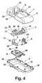
- Fig. 4 -is an exploded view of the holder according to the invention
- Fig. 1 -is a perspective view of the holder with the mobile phone seated in the holder as prior to introduction of the power supply connection
- Fig. 2 -is a detailed perspective view of the holder in the same position without a mobile phone
- Fig. 3 -is a detailed perspective view of the holder without a mobile phone, with a power supply connection in an "as-pressed" position
- Fig. 4 -is an exploded view of the holder according to the invention
- Fig. 1 -is
- FIG. 5 -is a front view of the holder, as prior to introduction of the power supply connection, with the upper part of the cover partly removed;
- Fig. 6 -is a front view of the holder, with a power supply connection in an "as-pressed" position, and with the upper part of the cover removed.
- the mobile phone holder with a lateral power supply connectionespecially for mechanical vehicles, according to the invention, as depicted in the drawing, includes the following basic components: a cover 1, within which there are all the elements of the holder, a base 2, which encloses these elements at the bottom, an upper catch 4 , a locking button 5 , which prevents a slide 3 from being moved, and a casing 8 enclosing the mechanism of the slide at its bottom.
- the slide 3is also provided with a power supply connection 6 , which has an electronic circuit board, not depicted on the drawing, and a plug 7 protruding from this connection.
- the cover 1has a shape of a cubicoid provided with a cavity 9 to accommodate a mobile phone, with an upper protrusion 10 and a lower protrusion 11 to protect the mobile phone 12 seated in the holder cavity 9 from being moved and with a shielding protrusion 13 , which shields and guides the button 14 of the slide 3 .
- the cover 1is also provided in the lower part of the cavity 9 with a flat protrusion 15 with a hole, through which the locking button 5 is adapted to go; the said protrusion 15 is an adapted surface of the cavity 9 to the model of a mobile phone.
- the cover 1is provided with a notch 16 , which is adapted to serve as a guide for a button 17 , which protrudes from the other side of the slide 3 .
- a similar notch 16which is adapted to serve as the other guide of the slide 3 , is provided in the base 2 .
- the base 2which has a shape of a rectangular plate, is provided at its edge with protrusions 18 with holes, through which the screws that mount the base 2 to the cover 1 are driven.
- the shape of the lower part of the baseis adapted to a hanger fixed to a proper element of a mechanical vehicle.
- the slide 3has a shape of a rectangular plate 20 , provided with guides 19 , mounted slideably on transverse protrusions of the lower part of the cover 1 (the protrusions not shown on the drawing).
- the plate 20is provided on its one side with a protrusion 21 with a hole 22 that is adapted to engage with a base 23 of the locking button 5 , which has a shape of a negative mapping of the protrusion 21 .
- the protrusion 21 of the plate 20is also provided with an additional blocking protrusion 24 , which is adapted to engage with the lower nib 25 of the catch 4 .
- Both the locking button 5 and the upper catch 4are provided with springs, 26 and 27 respectively.
- the power supply connection 6is provided within the button 14 of the slide 3 but the plug 7 protrudes outside the button 14 .
- the slide 3 , the upper catch 4 and the locking button 5are mounted within the cover 1 and are enclosed at the bottom with a shield 8 .
- the shield 8has a shape of a plate, which has projections 28 on the surface facing the slide 3 , which slides along these projections.
- the entire cover 1is enclosed at the bottom with the base 2 mounted to it.
- the mobile phone holder with a lateral power supply connectionoperates as follows: in its initial position, prior to the mobile phone is seated in the holder, the slide 3 stays in its rightmost position, whereas the locking button 5 is pulled upwards by the spring 26 .
- the base 23 of the locking button 5is in the hole 22 of the protrusion 21 of the plate 20 of the slide 3 ( Fig. 5 ).
- the slide 3In the position of the locking button 5 as protruding from the lower surface of the cavity 9 the slide 3 is blocked and protected against an accidental move.
- the mobile phone 12While the mobile phone 12 is seated into the cavity 9 of the holder, its rear wall presses the locking button 5 and the upper catch 4 concurrently, which results in that the catch 4 moves upwards.
- the plug 7 of the power supply connection 6has an appropriate length to provide an additional support to hold the phone as-seated in the cavity 9 of the holder.
Landscapes
- Engineering & Computer Science (AREA)
- Mechanical Engineering (AREA)
- Telephone Set Structure (AREA)
Abstract
Description
- This invention relates to a mobile phone holder with lateral power supply, especially for a mechanical vehicle, that consists of a base, a cover and a slide located slideably within the cover and connected to a power supply contact.
- Recently, phones with contacts located on a lateral wall have been more often used. The increasing use of mobile phones with the power supply connection located on a lateral wall can be justified by the need to increase the distance between the power supply connection and the phone antenna, which is usually located on the top wall or the bottom wall of the phone, and thus to eliminate interference of the connection on the quality of the signal received by the antenna. Placing the connection on a lateral wall of the phone has a significant influence on the design of mobile phone holders, since - in order to avoid damaging the connection when the phone is inserted into the holder - the connection cannot have a fixed location but has to be pulled out while the phone is seated in the holder.
- The US patent no.
US 5 708 707 describes a mobile phone holder wherein the bottom wall of the holder cavity, into which the phone is seated, is mounted slideably in the cover of the connection. When the phone is inserted into the holder the connection moves downwards and interlocks with a fixed contact located in the bottom wall of the cover. - The European patent no.
EP 1 055 562 A2 describes a mobile phone holder provided in its lower part with a slide, which slides along the axis of the phone in the guides located in the cover of the phone and which is provided with a contact that moves into the slot in the mobile phone if the slide is manually moved upwards. - In order to protect the contact in the slide from being damaged it is necessary to provide the bottom wall of the phone with a rounded shape and the top wall of the slide with a shape, which is the negative reflection of the wall of the phone. This design also prevents the phone from being inserted into the holder when the slide is moved away and the contact from being damaged.
- A mobile phone holder according to the preamble of claim 1 is known from
DE 10 2007 054 451 A1 . - The object of this invention is to provide an alternative mobile phone holder with a lateral power supply, especially for mechanical vehicles, wherein a contact of the holder is adapted to engage with a lateral connection of the mobile phone without a risk of damaging this contact when the phone is inserted into the holder.
- According to the invention there is provided a mobile phone holder having the features of claim 1.
- The mobile phone holder with a lateral power supply, especially for mechanical vehicles, according to the invention, is depicted in its embodiments on the drawings, where:
Fig. 1 - is a perspective view of the holder with the mobile phone seated in the holder as prior to introduction of the power supply connection;Fig. 2 - is a detailed perspective view of the holder in the same position without a mobile phone;Fig. 3 - is a detailed perspective view of the holder without a mobile phone, with a power supply connection in an "as-pressed" position;Fig. 4 - is an exploded view of the holder according to the invention;Fig. 5 - is a front view of the holder, as prior to introduction of the power supply connection, with the upper part of the cover partly removed;Fig. 6 - is a front view of the holder, with a power supply connection in an "as-pressed" position, and with the upper part of the cover removed. - The mobile phone holder with a lateral power supply connection, especially for mechanical vehicles, according to the invention, as depicted in the drawing, includes the following basic components: a cover 1, within which there are all the elements of the holder, a
base 2, which encloses these elements at the bottom, anupper catch 4, alocking button 5, which prevents aslide 3 from being moved, and acasing 8 enclosing the mechanism of the slide at its bottom. Theslide 3 is also provided with apower supply connection 6, which has an electronic circuit board, not depicted on the drawing, and aplug 7 protruding from this connection. The cover1 has a shape of a cubicoid provided with a cavity9 to accommodate a mobile phone, with anupper protrusion 10 and alower protrusion 11 to protect themobile phone 12 seated in the holder cavity9 from being moved and with ashielding protrusion 13, which shields and guides thebutton 14 of theslide 3. The cover1 is also provided in the lower part of the cavity9 with aflat protrusion 15 with a hole, through which thelocking button 5 is adapted to go; the saidprotrusion 15 is an adapted surface of the cavity9 to the model of a mobile phone. Moreover, on the side opposite to theprotrusion 13, the cover1 is provided with anotch 16, which is adapted to serve as a guide for abutton 17, which protrudes from the other side of theslide 3. Asimilar notch 16, which is adapted to serve as the other guide of theslide 3, is provided in thebase 2. Thebase 2, which has a shape of a rectangular plate, is provided at its edge withprotrusions 18 with holes, through which the screws that mount thebase 2 to the cover1 are driven. The shape of the lower part of the base is adapted to a hanger fixed to a proper element of a mechanical vehicle. Theslide 3 has a shape of arectangular plate 20, provided withguides 19, mounted slideably on transverse protrusions of the lower part of the cover1 (the protrusions not shown on the drawing). Theplate 20 is provided on its one side with aprotrusion 21 with ahole 22 that is adapted to engage with abase 23 of thelocking button 5, which has a shape of a negative mapping of theprotrusion 21. Theprotrusion 21 of theplate 20 is also provided with anadditional blocking protrusion 24, which is adapted to engage with thelower nib 25 of thecatch 4. - Both the
locking button 5 and theupper catch 4 are provided with springs,26 and27 respectively. - The
power supply connection 6 is provided within thebutton 14 of theslide 3 but theplug 7 protrudes outside thebutton 14. Theslide 3, theupper catch 4 and thelocking button 5 are mounted within the cover1 and are enclosed at the bottom with ashield 8. Theshield 8 has a shape of a plate, which hasprojections 28 on the surface facing theslide 3, which slides along these projections. - The entire cover1 is enclosed at the bottom with the
base 2 mounted to it. - The mobile phone holder with a lateral power supply connection, as described above, operates as follows: in its initial position, prior to the mobile phone is seated in the holder, the
slide 3 stays in its rightmost position, whereas thelocking button 5 is pulled upwards by thespring 26. Thebase 23 of thelocking button 5 is in thehole 22 of theprotrusion 21 of theplate 20 of the slide3 (Fig. 5 ). In the position of thelocking button 5 as protruding from the lower surface of the cavity9 theslide 3 is blocked and protected against an accidental move. While themobile phone 12 is seated into the cavity9 of the holder, its rear wall presses thelocking button 5 and theupper catch 4 concurrently, which results in that thecatch 4 moves upwards. When thelocking button 5 is pressed, itsbase 23 overcomes the pressure of thespring 26 and leaves thehole 22 in theplate 20. Theslide 3 is unlocked and its transverse move is now possible. At the same time thespring 27 presses theupper catch 4 thus making it move downwards and catch themobile phone 12 seating in the cavity9. In order to guide thepower supply connection 6 into a proper slot of the mobile phone thebutton 14 is pressed, which moves theslide 3 leftwards. In the leftmost position of theslide 3 itsprotrusion 24 goes under the lower nib of theupper catch 4, thus blocking its move and locking the phone in the holder. - Thanks to this arrangement moving the
slide 3 results in a concurrent turning the phone on and protecting it from dropping out from the cavity9. - In an protruding position the
plug 7 of thepower supply connection 6, according to the invention, has an appropriate length to provide an additional support to hold the phone as-seated in the cavity9 of the holder. - In order to remove the
mobile phone 12 from the holder it is necessary to move theslide 3 first into its rightmost position, i.e. press thebutton 17, which results in a move of theplug 7 off the power supply slot of the phone and a concurrent unlocking thecatch 4 by theprotrusion 24 of theplate 20. The mobile phone can be then removed from the cavity9 without any damage to theplug 7. Once the phone is removed, thebutton 5 returns into its initial position under the force of thespring 26 and again blocks theslide 3. This position protects theplug 7 from being unintentionally pushed out from theshielding protrusion 13 and damaged by an improper attempt to place themobile phone 12into the holder. - 1
- cover
- 2
- base
- 3
- slide
- 4
- upper catch
- 5
- locking button
- 6
- power supply connection
- 7
- plug
- 8
- shield for the slide
- 9
- cavity
- 10
- upper protrusion
- 11
- lower protrusion
- 12
- mobile phone
- 13
- shielding protrusion
- 14
- button
- 15
- flat protrusion
- 16
- notch
- 17
- button
- 18
- protrusions
- 19
- guides
- 20
- plate
- 21
- protrusion
- 22
- hole
- 23
- base
- 24
- additional blocking protrusion
- 25
- lower nib
- 26
- spring
- 27
- spring
- 28
- projections.
Claims (4)
- A mobile phone holder with a lateral power supply connection, especially for mechanical vehicles, which consists of a base, a cover and a slide mounted slideably within the cover and connected to a power supply connection,characterized in that the slide (3) plate (20), mounted slideably in the cover (1) has a protrusion (21), which is provided with a hole (22) and an additional protrusion (24); the said hole (22) is a negative mapping of a base (23) of a locking button (5) that is mounted slideably within the area of a holder cavity (9); the said additional protrusion (24) is adapted to engage with a nib (25) on an upper catch (4) for the phone, which results in locking the catch when the phone is seated and locked in the holder cavity (9) and the position of the slide corresponds to an "as-pressed" position of the power supply connection (6).
- The holder according to the Claim 1, wherein the slide (3) has a shape of a flat rectangular plate20, mounted slideably in the cover (1) and provided, on its one side, with a button (14) connected with the power supply connection (6), as well as, on the other side, with a button (17) to pull the power supply connection (6) out; the said plate is connected with the protrusion (21).
- The holder according to the Claim 1 or 2, wherein the power supply connection (6) is fixed within the button (14) and the plug (7) protrudes outside the button (14) and has an appropriate length to provide an additional support to hold the phone (12) as-seated in the cavity (9) of the holder.
- The holder according to the Claims 1 to 3, wherein the plate (20) of the slide (3) is mounted slideably in notches (16) of the cover (1) and the base (2) and is provided with guides (19), which are adapted to engage with projections (28) of a shield (8).
Priority Applications (3)
| Application Number | Priority Date | Filing Date | Title |
|---|---|---|---|
| AT08460035TATE551231T1 (en) | 2008-08-21 | 2008-08-21 | MOBILE PHONE HOLDER WITH SIDE POWER CONNECTOR, ESPECIALLY FOR A MECHANICAL VEHICLE |
| EP08460035AEP2159107B1 (en) | 2008-08-21 | 2008-08-21 | A mobile phone holder with lateral power supply especially for a mechanical vehicle |
| US12/540,569US20100048260A1 (en) | 2008-08-21 | 2009-08-13 | Mobile phone holder with lateral power supply, especially for a mechanical vehicle |
Applications Claiming Priority (1)
| Application Number | Priority Date | Filing Date | Title |
|---|---|---|---|
| EP08460035AEP2159107B1 (en) | 2008-08-21 | 2008-08-21 | A mobile phone holder with lateral power supply especially for a mechanical vehicle |
Publications (2)
| Publication Number | Publication Date |
|---|---|
| EP2159107A1 EP2159107A1 (en) | 2010-03-03 |
| EP2159107B1true EP2159107B1 (en) | 2012-03-28 |
Family
ID=40350180
Family Applications (1)
| Application Number | Title | Priority Date | Filing Date |
|---|---|---|---|
| EP08460035ANot-in-forceEP2159107B1 (en) | 2008-08-21 | 2008-08-21 | A mobile phone holder with lateral power supply especially for a mechanical vehicle |
Country Status (3)
| Country | Link |
|---|---|
| US (1) | US20100048260A1 (en) |
| EP (1) | EP2159107B1 (en) |
| AT (1) | ATE551231T1 (en) |
Families Citing this family (5)
| Publication number | Priority date | Publication date | Assignee | Title |
|---|---|---|---|---|
| ATE482851T1 (en)* | 2008-08-06 | 2010-10-15 | Bury Sp Zoo | MOBILE PHONE HOLDER FOR VEHICLES |
| US20130002109A1 (en)* | 2011-06-30 | 2013-01-03 | Peter Benjamin Gloria | Mobile Electronic Device Housing |
| US9130384B2 (en) | 2011-10-06 | 2015-09-08 | Prong, Inc. | Smart phone and/or consumer electronics device charger system |
| DE102013111478A1 (en)* | 2013-10-17 | 2015-04-23 | Andreas Filosi | Holder for a mobile telecommunication terminal |
| JP7039313B2 (en)* | 2018-02-14 | 2022-03-22 | オムロン株式会社 | Wireless communication devices, sensor devices and wearable devices |
Family Cites Families (8)
| Publication number | Priority date | Publication date | Assignee | Title |
|---|---|---|---|---|
| US5463688A (en)* | 1994-05-19 | 1995-10-31 | Motorola | Telephone mounting receptacle having opposed retractable latch members |
| FI108492B (en) | 1995-01-20 | 2002-01-31 | Nokia Corp | Phone support |
| DE29909215U1 (en) | 1999-05-28 | 2000-10-05 | Peiker, Andreas, 61381 Friedrichsdorf | Holder for radio telephones |
| US20020176571A1 (en)* | 2001-05-22 | 2002-11-28 | Richard Louh | Multi-function car phone holder |
| US7522889B2 (en)* | 2002-12-30 | 2009-04-21 | Symbol Technologies, Inc. | Rugged design for hand held mobile terminals |
| DE102006012763B3 (en)* | 2006-03-17 | 2007-10-18 | Bury Gmbh & Co. Kg | Device holder with a movable contact plug |
| US7425132B2 (en)* | 2006-06-20 | 2008-09-16 | Hsien-Lin Yang | Power adaptor with retractable plug |
| DE102007054451A1 (en)* | 2006-11-13 | 2008-05-15 | Peiker Acustic Gmbh & Co. Kg | Holding device for electronic device i.e. mobile phone, has base body, and carrier comprising interface, which is movable from position to another position when carrier moves from holding position to retaining position |
- 2008
- 2008-08-21EPEP08460035Apatent/EP2159107B1/ennot_activeNot-in-force
- 2008-08-21ATAT08460035Tpatent/ATE551231T1/enactive
- 2009
- 2009-08-13USUS12/540,569patent/US20100048260A1/ennot_activeAbandoned
Also Published As
| Publication number | Publication date |
|---|---|
| EP2159107A1 (en) | 2010-03-03 |
| ATE551231T1 (en) | 2012-04-15 |
| US20100048260A1 (en) | 2010-02-25 |
Similar Documents
| Publication | Publication Date | Title |
|---|---|---|
| EP2080672B1 (en) | A mobile phone holder with lateral connections, especially for a vehicle | |
| EP2159107B1 (en) | A mobile phone holder with lateral power supply especially for a mechanical vehicle | |
| US7160131B1 (en) | SIM card holder | |
| EP2151353B1 (en) | A mobile phone holder for vehicles | |
| EP2026544B1 (en) | A mobile phone holder for mechanical vehicles | |
| EP1760997A1 (en) | Battery locking mechanism for an electronic device | |
| US6561431B2 (en) | Card reader and the mobile electronic device equipped with it | |
| US20070125855A1 (en) | Chip card retaining mechanism | |
| CN102969613A (en) | Connector | |
| US20100124847A1 (en) | Usb connector and method of manufacture | |
| CN104241899B (en) | Connector device and electronic apparatus including thereof | |
| KR20080101669A (en) | Connector for card | |
| EP1536365A2 (en) | Card holding structure for portable electronic device | |
| JPH07169533A (en) | Basil connector | |
| JP2013178888A (en) | Tray type card connector | |
| JP2008130461A (en) | Card mounting device | |
| KR101833722B1 (en) | Connector Apparatus with Receiving Part for Card | |
| US20070075197A1 (en) | Mount for a phone holder | |
| US20040132343A1 (en) | Adapter for a telephone holder of a hands-free device | |
| SG186516A1 (en) | Card connector | |
| EP2325049B1 (en) | A mobile phone holder with lateral connectors | |
| JP2012146486A (en) | Card connector with removing function | |
| US7019612B2 (en) | Fuse seat for filter | |
| EP2230770A1 (en) | A universal mobile phone holder, especially for mechanical vehicles, with an adaptable part adjusting the holder to the size of the mobile phone | |
| JP2010232097A (en) | Card connector |
Legal Events
| Date | Code | Title | Description |
|---|---|---|---|
| PUAI | Public reference made under article 153(3) epc to a published international application that has entered the european phase | Free format text:ORIGINAL CODE: 0009012 | |
| AK | Designated contracting states | Kind code of ref document:A1 Designated state(s):AT BE BG CH CY CZ DE DK EE ES FI FR GB GR HR HU IE IS IT LI LT LU LV MC MT NL NO PL PT RO SE SI SK TR | |
| AX | Request for extension of the european patent | Extension state:AL BA MK RS | |
| 17P | Request for examination filed | Effective date:20100430 | |
| AKX | Designation fees paid | Designated state(s):AT BE BG CH CY CZ DE DK EE ES FI FR GB GR HR HU IE IS IT LI LT LU LV MC MT NL NO PL PT RO SE SI SK TR | |
| GRAP | Despatch of communication of intention to grant a patent | Free format text:ORIGINAL CODE: EPIDOSNIGR1 | |
| RIC1 | Information provided on ipc code assigned before grant | Ipc:H04M 1/04 20060101ALI20111205BHEP Ipc:B60R 11/02 20060101AFI20111205BHEP | |
| GRAS | Grant fee paid | Free format text:ORIGINAL CODE: EPIDOSNIGR3 | |
| GRAA | (expected) grant | Free format text:ORIGINAL CODE: 0009210 | |
| AK | Designated contracting states | Kind code of ref document:B1 Designated state(s):AT BE BG CH CY CZ DE DK EE ES FI FR GB GR HR HU IE IS IT LI LT LU LV MC MT NL NO PL PT RO SE SI SK TR | |
| REG | Reference to a national code | Ref country code:GB Ref legal event code:FG4D | |
| REG | Reference to a national code | Ref country code:CH Ref legal event code:EP | |
| REG | Reference to a national code | Ref country code:NL Ref legal event code:T3 | |
| REG | Reference to a national code | Ref country code:AT Ref legal event code:REF Ref document number:551231 Country of ref document:AT Kind code of ref document:T Effective date:20120415 | |
| REG | Reference to a national code | Ref country code:IE Ref legal event code:FG4D | |
| REG | Reference to a national code | Ref country code:DE Ref legal event code:R096 Ref document number:602008014428 Country of ref document:DE Effective date:20120524 | |
| PG25 | Lapsed in a contracting state [announced via postgrant information from national office to epo] | Ref country code:HR Free format text:LAPSE BECAUSE OF FAILURE TO SUBMIT A TRANSLATION OF THE DESCRIPTION OR TO PAY THE FEE WITHIN THE PRESCRIBED TIME-LIMIT Effective date:20120328 Ref country code:NO Free format text:LAPSE BECAUSE OF FAILURE TO SUBMIT A TRANSLATION OF THE DESCRIPTION OR TO PAY THE FEE WITHIN THE PRESCRIBED TIME-LIMIT Effective date:20120628 Ref country code:LT Free format text:LAPSE BECAUSE OF FAILURE TO SUBMIT A TRANSLATION OF THE DESCRIPTION OR TO PAY THE FEE WITHIN THE PRESCRIBED TIME-LIMIT Effective date:20120328 | |
| LTIE | Lt: invalidation of european patent or patent extension | Effective date:20120328 | |
| PG25 | Lapsed in a contracting state [announced via postgrant information from national office to epo] | Ref country code:LV Free format text:LAPSE BECAUSE OF FAILURE TO SUBMIT A TRANSLATION OF THE DESCRIPTION OR TO PAY THE FEE WITHIN THE PRESCRIBED TIME-LIMIT Effective date:20120328 Ref country code:GR Free format text:LAPSE BECAUSE OF FAILURE TO SUBMIT A TRANSLATION OF THE DESCRIPTION OR TO PAY THE FEE WITHIN THE PRESCRIBED TIME-LIMIT Effective date:20120629 Ref country code:FI Free format text:LAPSE BECAUSE OF FAILURE TO SUBMIT A TRANSLATION OF THE DESCRIPTION OR TO PAY THE FEE WITHIN THE PRESCRIBED TIME-LIMIT Effective date:20120328 | |
| REG | Reference to a national code | Ref country code:AT Ref legal event code:MK05 Ref document number:551231 Country of ref document:AT Kind code of ref document:T Effective date:20120328 | |
| PG25 | Lapsed in a contracting state [announced via postgrant information from national office to epo] | Ref country code:CY Free format text:LAPSE BECAUSE OF FAILURE TO SUBMIT A TRANSLATION OF THE DESCRIPTION OR TO PAY THE FEE WITHIN THE PRESCRIBED TIME-LIMIT Effective date:20120328 | |
| PG25 | Lapsed in a contracting state [announced via postgrant information from national office to epo] | Ref country code:PL Free format text:LAPSE BECAUSE OF FAILURE TO SUBMIT A TRANSLATION OF THE DESCRIPTION OR TO PAY THE FEE WITHIN THE PRESCRIBED TIME-LIMIT Effective date:20120328 Ref country code:BE Free format text:LAPSE BECAUSE OF FAILURE TO SUBMIT A TRANSLATION OF THE DESCRIPTION OR TO PAY THE FEE WITHIN THE PRESCRIBED TIME-LIMIT Effective date:20120328 Ref country code:RO Free format text:LAPSE BECAUSE OF FAILURE TO SUBMIT A TRANSLATION OF THE DESCRIPTION OR TO PAY THE FEE WITHIN THE PRESCRIBED TIME-LIMIT Effective date:20120328 Ref country code:SE Free format text:LAPSE BECAUSE OF FAILURE TO SUBMIT A TRANSLATION OF THE DESCRIPTION OR TO PAY THE FEE WITHIN THE PRESCRIBED TIME-LIMIT Effective date:20120328 Ref country code:IS Free format text:LAPSE BECAUSE OF FAILURE TO SUBMIT A TRANSLATION OF THE DESCRIPTION OR TO PAY THE FEE WITHIN THE PRESCRIBED TIME-LIMIT Effective date:20120728 Ref country code:EE Free format text:LAPSE BECAUSE OF FAILURE TO SUBMIT A TRANSLATION OF THE DESCRIPTION OR TO PAY THE FEE WITHIN THE PRESCRIBED TIME-LIMIT Effective date:20120328 Ref country code:CZ Free format text:LAPSE BECAUSE OF FAILURE TO SUBMIT A TRANSLATION OF THE DESCRIPTION OR TO PAY THE FEE WITHIN THE PRESCRIBED TIME-LIMIT Effective date:20120328 Ref country code:SI Free format text:LAPSE BECAUSE OF FAILURE TO SUBMIT A TRANSLATION OF THE DESCRIPTION OR TO PAY THE FEE WITHIN THE PRESCRIBED TIME-LIMIT Effective date:20120328 | |
| PG25 | Lapsed in a contracting state [announced via postgrant information from national office to epo] | Ref country code:PT Free format text:LAPSE BECAUSE OF FAILURE TO SUBMIT A TRANSLATION OF THE DESCRIPTION OR TO PAY THE FEE WITHIN THE PRESCRIBED TIME-LIMIT Effective date:20120730 Ref country code:SK Free format text:LAPSE BECAUSE OF FAILURE TO SUBMIT A TRANSLATION OF THE DESCRIPTION OR TO PAY THE FEE WITHIN THE PRESCRIBED TIME-LIMIT Effective date:20120328 | |
| PG25 | Lapsed in a contracting state [announced via postgrant information from national office to epo] | Ref country code:AT Free format text:LAPSE BECAUSE OF FAILURE TO SUBMIT A TRANSLATION OF THE DESCRIPTION OR TO PAY THE FEE WITHIN THE PRESCRIBED TIME-LIMIT Effective date:20120328 Ref country code:DK Free format text:LAPSE BECAUSE OF FAILURE TO SUBMIT A TRANSLATION OF THE DESCRIPTION OR TO PAY THE FEE WITHIN THE PRESCRIBED TIME-LIMIT Effective date:20120328 | |
| PLBE | No opposition filed within time limit | Free format text:ORIGINAL CODE: 0009261 | |
| STAA | Information on the status of an ep patent application or granted ep patent | Free format text:STATUS: NO OPPOSITION FILED WITHIN TIME LIMIT | |
| PG25 | Lapsed in a contracting state [announced via postgrant information from national office to epo] | Ref country code:IT Free format text:LAPSE BECAUSE OF FAILURE TO SUBMIT A TRANSLATION OF THE DESCRIPTION OR TO PAY THE FEE WITHIN THE PRESCRIBED TIME-LIMIT Effective date:20120328 | |
| 26N | No opposition filed | Effective date:20130103 | |
| REG | Reference to a national code | Ref country code:NL Ref legal event code:V1 Effective date:20130301 | |
| REG | Reference to a national code | Ref country code:CH Ref legal event code:PL | |
| PG25 | Lapsed in a contracting state [announced via postgrant information from national office to epo] | Ref country code:MC Free format text:LAPSE BECAUSE OF NON-PAYMENT OF DUE FEES Effective date:20120831 | |
| REG | Reference to a national code | Ref country code:DE Ref legal event code:R097 Ref document number:602008014428 Country of ref document:DE Effective date:20130103 | |
| PG25 | Lapsed in a contracting state [announced via postgrant information from national office to epo] | Ref country code:LI Free format text:LAPSE BECAUSE OF NON-PAYMENT OF DUE FEES Effective date:20120831 Ref country code:CH Free format text:LAPSE BECAUSE OF NON-PAYMENT OF DUE FEES Effective date:20120831 Ref country code:NL Free format text:LAPSE BECAUSE OF NON-PAYMENT OF DUE FEES Effective date:20130301 Ref country code:ES Free format text:LAPSE BECAUSE OF FAILURE TO SUBMIT A TRANSLATION OF THE DESCRIPTION OR TO PAY THE FEE WITHIN THE PRESCRIBED TIME-LIMIT Effective date:20120709 | |
| REG | Reference to a national code | Ref country code:FR Ref legal event code:ST Effective date:20130430 | |
| REG | Reference to a national code | Ref country code:IE Ref legal event code:MM4A | |
| PG25 | Lapsed in a contracting state [announced via postgrant information from national office to epo] | Ref country code:BG Free format text:LAPSE BECAUSE OF FAILURE TO SUBMIT A TRANSLATION OF THE DESCRIPTION OR TO PAY THE FEE WITHIN THE PRESCRIBED TIME-LIMIT Effective date:20120628 Ref country code:IE Free format text:LAPSE BECAUSE OF NON-PAYMENT OF DUE FEES Effective date:20120821 | |
| PG25 | Lapsed in a contracting state [announced via postgrant information from national office to epo] | Ref country code:FR Free format text:LAPSE BECAUSE OF NON-PAYMENT OF DUE FEES Effective date:20120831 | |
| PG25 | Lapsed in a contracting state [announced via postgrant information from national office to epo] | Ref country code:MT Free format text:LAPSE BECAUSE OF FAILURE TO SUBMIT A TRANSLATION OF THE DESCRIPTION OR TO PAY THE FEE WITHIN THE PRESCRIBED TIME-LIMIT Effective date:20120328 | |
| PG25 | Lapsed in a contracting state [announced via postgrant information from national office to epo] | Ref country code:TR Free format text:LAPSE BECAUSE OF FAILURE TO SUBMIT A TRANSLATION OF THE DESCRIPTION OR TO PAY THE FEE WITHIN THE PRESCRIBED TIME-LIMIT Effective date:20120328 | |
| PG25 | Lapsed in a contracting state [announced via postgrant information from national office to epo] | Ref country code:LU Free format text:LAPSE BECAUSE OF NON-PAYMENT OF DUE FEES Effective date:20120821 | |
| PG25 | Lapsed in a contracting state [announced via postgrant information from national office to epo] | Ref country code:HU Free format text:LAPSE BECAUSE OF FAILURE TO SUBMIT A TRANSLATION OF THE DESCRIPTION OR TO PAY THE FEE WITHIN THE PRESCRIBED TIME-LIMIT Effective date:20080821 | |
| REG | Reference to a national code | Ref country code:DE Ref legal event code:R082 Ref document number:602008014428 Country of ref document:DE Representative=s name:GRAMM, LINS & PARTNER PATENT- UND RECHTSANWAEL, DE | |
| PGFP | Annual fee paid to national office [announced via postgrant information from national office to epo] | Ref country code:DE Payment date:20190829 Year of fee payment:12 | |
| PGFP | Annual fee paid to national office [announced via postgrant information from national office to epo] | Ref country code:GB Payment date:20190808 Year of fee payment:12 | |
| REG | Reference to a national code | Ref country code:DE Ref legal event code:R119 Ref document number:602008014428 Country of ref document:DE | |
| GBPC | Gb: european patent ceased through non-payment of renewal fee | Effective date:20200821 | |
| PG25 | Lapsed in a contracting state [announced via postgrant information from national office to epo] | Ref country code:DE Free format text:LAPSE BECAUSE OF NON-PAYMENT OF DUE FEES Effective date:20210302 | |
| PG25 | Lapsed in a contracting state [announced via postgrant information from national office to epo] | Ref country code:GB Free format text:LAPSE BECAUSE OF NON-PAYMENT OF DUE FEES Effective date:20200821 |