EP2158579B1 - Lighting system with traffic management capabilities - Google Patents
Lighting system with traffic management capabilitiesDownload PDFInfo
- Publication number
- EP2158579B1 EP2158579B1EP08772824.2AEP08772824AEP2158579B1EP 2158579 B1EP2158579 B1EP 2158579B1EP 08772824 AEP08772824 AEP 08772824AEP 2158579 B1EP2158579 B1EP 2158579B1
- Authority
- EP
- European Patent Office
- Prior art keywords
- light
- light source
- traffic
- visible
- signal
- Prior art date
- Legal status (The legal status is an assumption and is not a legal conclusion. Google has not performed a legal analysis and makes no representation as to the accuracy of the status listed.)
- Active
Links
Images


Classifications
- G—PHYSICS
- G08—SIGNALLING
- G08G—TRAFFIC CONTROL SYSTEMS
- G08G1/00—Traffic control systems for road vehicles
- G08G1/01—Detecting movement of traffic to be counted or controlled
- G08G1/0104—Measuring and analyzing of parameters relative to traffic conditions
- G—PHYSICS
- G01—MEASURING; TESTING
- G01S—RADIO DIRECTION-FINDING; RADIO NAVIGATION; DETERMINING DISTANCE OR VELOCITY BY USE OF RADIO WAVES; LOCATING OR PRESENCE-DETECTING BY USE OF THE REFLECTION OR RERADIATION OF RADIO WAVES; ANALOGOUS ARRANGEMENTS USING OTHER WAVES
- G01S17/00—Systems using the reflection or reradiation of electromagnetic waves other than radio waves, e.g. lidar systems
- G01S17/02—Systems using the reflection of electromagnetic waves other than radio waves
- G01S17/04—Systems determining the presence of a target
- G—PHYSICS
- G01—MEASURING; TESTING
- G01S—RADIO DIRECTION-FINDING; RADIO NAVIGATION; DETERMINING DISTANCE OR VELOCITY BY USE OF RADIO WAVES; LOCATING OR PRESENCE-DETECTING BY USE OF THE REFLECTION OR RERADIATION OF RADIO WAVES; ANALOGOUS ARRANGEMENTS USING OTHER WAVES
- G01S17/00—Systems using the reflection or reradiation of electromagnetic waves other than radio waves, e.g. lidar systems
- G01S17/02—Systems using the reflection of electromagnetic waves other than radio waves
- G01S17/06—Systems determining position data of a target
- G01S17/08—Systems determining position data of a target for measuring distance only
- G01S17/10—Systems determining position data of a target for measuring distance only using transmission of interrupted, pulse-modulated waves
- G—PHYSICS
- G01—MEASURING; TESTING
- G01S—RADIO DIRECTION-FINDING; RADIO NAVIGATION; DETERMINING DISTANCE OR VELOCITY BY USE OF RADIO WAVES; LOCATING OR PRESENCE-DETECTING BY USE OF THE REFLECTION OR RERADIATION OF RADIO WAVES; ANALOGOUS ARRANGEMENTS USING OTHER WAVES
- G01S17/00—Systems using the reflection or reradiation of electromagnetic waves other than radio waves, e.g. lidar systems
- G01S17/02—Systems using the reflection of electromagnetic waves other than radio waves
- G01S17/50—Systems of measurement based on relative movement of target
- G01S17/58—Velocity or trajectory determination systems; Sense-of-movement determination systems
- G—PHYSICS
- G01—MEASURING; TESTING
- G01S—RADIO DIRECTION-FINDING; RADIO NAVIGATION; DETERMINING DISTANCE OR VELOCITY BY USE OF RADIO WAVES; LOCATING OR PRESENCE-DETECTING BY USE OF THE REFLECTION OR RERADIATION OF RADIO WAVES; ANALOGOUS ARRANGEMENTS USING OTHER WAVES
- G01S7/00—Details of systems according to groups G01S13/00, G01S15/00, G01S17/00
- G01S7/48—Details of systems according to groups G01S13/00, G01S15/00, G01S17/00 of systems according to group G01S17/00
- G01S7/4808—Evaluating distance, position or velocity data
- G—PHYSICS
- G08—SIGNALLING
- G08G—TRAFFIC CONTROL SYSTEMS
- G08G1/00—Traffic control systems for road vehicles
- G08G1/07—Controlling traffic signals
- G—PHYSICS
- G08—SIGNALLING
- G08G—TRAFFIC CONTROL SYSTEMS
- G08G1/00—Traffic control systems for road vehicles
- G08G1/09—Arrangements for giving variable traffic instructions
- G08G1/095—Traffic lights
- Y—GENERAL TAGGING OF NEW TECHNOLOGICAL DEVELOPMENTS; GENERAL TAGGING OF CROSS-SECTIONAL TECHNOLOGIES SPANNING OVER SEVERAL SECTIONS OF THE IPC; TECHNICAL SUBJECTS COVERED BY FORMER USPC CROSS-REFERENCE ART COLLECTIONS [XRACs] AND DIGESTS
- Y02—TECHNOLOGIES OR APPLICATIONS FOR MITIGATION OR ADAPTATION AGAINST CLIMATE CHANGE
- Y02B—CLIMATE CHANGE MITIGATION TECHNOLOGIES RELATED TO BUILDINGS, e.g. HOUSING, HOUSE APPLIANCES OR RELATED END-USER APPLICATIONS
- Y02B20/00—Energy efficient lighting technologies, e.g. halogen lamps or gas discharge lamps
- Y02B20/40—Control techniques providing energy savings, e.g. smart controller or presence detection
Definitions
- the present applicationrelates to lighting systems, and more particularly to a lighting system providing traffic management capabilities by the control of the light output of the lighting system.
- AMSAdvanced Management Transportation Systems
- intrusive detectorsinvolves inductive loop detectors that are still a common technology for detecting vehicles even if that technology has disadvantages such as lengthy disruption to the traffic flow during installation and maintenance, relatively high cost, high failure rate and inflexibility.
- Other detectorslike cameras with video processing, also have their limitations and the market is still searching for alternatives to inductive loops.
- Information from sensorsis the base point in the optimization of traffic management, particularly adaptive timing for traffic light signalling.
- Well managed adaptive timingcan result in reductions of fuel consumption, fewer vehicle emissions and a reduction in waste of time.
- sensor mounting requirementsare often costly and cause traffic disruption during installation.
- the present lighting systemadds detection capabilities to perceive the presence and measure the velocity of objects such as automobiles, trucks, pedestrian and other users, to lighting modules for transportation applications like traffic signal, pedestrian control, rails signal, street light, message board and speed monitoring board.
- a Light Emitting DiodeLED
- Other light sources, such as lasers,can be integrated into the lighting system and used as a source for the detection sub-system.
- a method for controlling traffic signallingcomprising: providing a traffic light with a visible-light source emitting visible light and having a function of actuating alternately at least two different traffic signal states for traffic signalling; driving the visible-light source to emit light in a traffic signal state in a predetermined mode, with visible light in the predetermined mode being emitted so as to be visible to an unaided human eye; receiving a reflection/backscatter of the emitted visible light from an object; identifying at least one of a presence and a position of the object as a function of the reflection/backscatter received and of the predetermined mode; and controlling said traffic signal states actuated by the visible-light source as a function of the at least one of the presence and the position of the object.
- the methodcomprises retrofitting an existing traffic light with a source controller for driving the visible-light source and a detector for receiving the reflection/backscatter of the emitted visible light from the object.
- driving the visible-light source in the predetermined modecomprises at least one of pulsating and modulating the visible light.
- receiving the reflection/backscattercomprises filtering given light wavelengths.
- identifying at least one of a presence and a position of the objectcomprises calculating at least a distance of the object by measuring a time delay between emitting the visible light and receiving the reflection/backscatter from the object.
- calculating the distancecomprises continuously calculating the distance so as to calculate a speed of the object.
- the methodcomprises providing an auxiliary light source in association with the traffic light; driving the auxiliary light source concurrently with the visible-light source in another predetermined mode to emit auxiliary light; receiving a reflection/backscatter of the auxiliary light from an object; identifying at least one of the presence and the position of the object as a function of at least the reflection/backscatter received from the auxiliary light and the predetermined modes; and controlling said signal states actuated by the visible-light source as a function of at least one of the presence and the position of the object.
- driving the auxiliary light sourcecomprises driving the auxiliary light source into emitting light non-visible to an unaided human eye.
- driving the visible-light source to emit visible light in a predetermined modecomprises pulsating a light emission diode to produce light pulses having a width of less than 50 ns.
- controlling said traffic signal statescomprises switching said traffic signal states as a function of the at least one of the presence and the position of the object.
- a traffic-signal lighting systemcomprising: a light source emitting visible light and having a function of emitting visible light in an illumination mode for actuation alternately at least two traffic signal states; a source controller for driving the light source into emitting one of the traffic signal states in a predetermined mode with visible light in the predetermined mode being emitted such that the light source maintains said function of emitting traffic signals visible to an unaided human eye in the environment while being driven by the source controller; an optical detector adapted to detect the visible light as reflected/backscattered by an object to produce detection data; and a data/signal processor for receiving detection data from the optical detector, the data/signal processor producing a data output associated to the object as a function of the predetermined mode and the detection data, and for commanding the light source into controlling said traffic signal states as a function of the data output.
- the traffic-signal lighting systemcomprises an external traffic-management system connected to the data/signal processor for managing traffic as a function of the detection data received from the data/signal processor.
- the optical detectorcomprises a plurality of sub-detectors each detecting a specific zone.
- the traffic-signal lighting systemcomprises a scanning mechanism in association with the optical detector so as to cause a scanning motion of a field of view of the optical detector within a range of illumination of emitted light of the light sources.
- the optical detectorhas an array of sub-detectors.
- the source controllercomprises a pulse/modulation driver to drive the visible-light source in the predetermined mode.
- the source controllercomprises an illumination driver to drive the light source into emitting light of suitable intensity to illuminate an environment.
- the light sourcehas a plurality of lights, with at least one of the lights of the light source being driven by the illumination driver to illuminate the environment, while at least another one of the lights of the light source is driven by the pulse/modulation driver to emit the visible light in the predetermined mode.
- the optical detectorhas a filtering device to filter given light wavelengths of the reflected/backscattered visible light.
- the traffic-signal lighting systemcomprises an auxiliary light source for emitting an auxiliary light in another predetermined mode concurrently with the visible-light source, the reflection/backscatter of the auxiliary light received from an object being used to produce said a data output associated to the object.
- the auxiliary light sourcecomprises a non-visible light source.
- said light sourcecomprises a light emitting diode light source.
- the data/signal processorcommands the light source into switching said traffic signal states as a function of the data output.
- the lighting system 10has a processing/driving unit 10A and a traffic light unit 10B. It is pointed out that more than one traffic light unit 10B may be used with a common processing/driving unit 10A.
- the traffic light unit 10Bhas a light source 12.
- the visible-light source 12has as a first function the emission of visible light for visual communication of information, like signalling, for human vision. Accordingly, the light source 12 emits the various light signals associated with a traffic light, such as emitting light of different colors (i.e., green, red, yellow), and in different shapes (e.g., circles, arrows).
- the visible-light source 12has solid-state lighting devices, LEDs or OLEDs for instance, and may be is part of a traffic light unit, for car or for pedestrian signalling, to name a few applications.
- the LEDsare regrouped to emit different traffic signals of different colors as required by traffic management signalling.
- the visible-light source 12is connected to a source controller 14, so as to be driven into producing visible light.
- the system 10performs detection of objects and particles (vehicle, pedestrian, airborne particles, gases and liquids) when these objects are part of the environment/scene illuminated by the light source 12. Accordingly, the source controller 14 drives the visible-light source 12 in a predetermined mode, such that the emitted light takes the form of a light signal, for instance by way of amplitude-modulated or pulsed light emission.
- These light signalsare such that they can be used to provide the lighting illumination level required by the application, through data/signal processor 18 and source controller 14, while producing a detectable signal. Accordingly, it is possible to obtain a light level equivalent to a continuous light source by modulating the light signal fast enough (e.g., frequency more than 100 Hz) to be generally imperceptible to the human eye and having an average light power equivalent to a continuous light source.
- the light signal fast enoughe.g., frequency more than 100 Hz
- the source controller 14is designed to provide an illumination drive signal, such as a constant DC signal or a pulse-width modulated (PWM) signal, that is normally used in lighting systems to produce the required illumination and control its intensity.
- the illumination drive signalis produced by the illumination driver sub-module 14A of the controller 14.
- the sub-module 14Bemits a modulated/pulsed driving signal which supplies the fast modulation/pulse sequence used for remote object detection.
- the amplitude of short-pulsecan be several time the nominal value (such as 20 times) while the duty cycle is low (typ. ⁇ 0.1%).
- the modulator driver sub-module 14Bis used to send data for remote optical detection.
- Both the illumination drive signals and the modulated/pulsed driving signalscan be produced independently or in combination. Sequencing of the drive signals is controlled by the data/signal processor 18.
- the light source 12can be monitored and the resulting parameters sent to the data/signal processor 18 for optimization of data processing. For example, a match filter can be done between the light output signal or auxiliary light output signal and input light signal from the optical detector 16, as will be described hereinafter.
- Random pulsing modulationcan be used to discriminate each system.
- the visible-light source 12typically uses LEDs. More specifically, LEDs are well suited to be used in the lighting system 10 as LED intensity can be efficiently modulated/pulsed at suitable speed. Using this possibility, current traffic light units already installed and featuring LEDs for standard lighting applications can be used as the light source 12 for sensing applications. These applications include non-exclusively presence detection for energy savings, distance and speed measurements, fog, rain, snow or smoke detection, and spectroscopic measurements for gas emission or smog detection.
- the detector 16is an optical detector (or detectors) provided so as to collect light emitted by the light source 12 or auxiliary light source as described hereinafter and back-scattered by the objects/particles A.
- the light signalcan also come from an object A being the direct source of this light (such as a remote control) in order to send information to the data/signal processor through the optical detector 16.
- the optical detector 16is as an example any of photodiodes, avalanche photodiodes (APD), photomultipliers (PMT), cmos or CCD array sensors, amongst others.
- Filtersare typically provided with the detector 16 to control ambient light background emitted from sources other than the lighting system 10. Filters can also be used for spectroscopic measurements and to enhance performance of the light source 12. For instance, a pulsed visible-light signal from a white LED filtered to blue is faster as compared with an unfiltered light signal but has less power. In the case of white LEDs, the phosphor used converts the blue light of the LED junction into visible light with a certain time delay because of the phosphorescence emission lifetime.
- the blue part of the emission spectrum of white phosphorescent LEDsis used, with proper wavelength filtering at detection, to allow faster light modulation, since the blue part will not suffer the phosphorescent material usual modulation speed reduction. This would allow either faster modulation speeds or light pulses while keeping the broadband illumination of the white LED for the scene illumination.
- the full bandwidthis more appropriate.
- a combination of blue-filter detector and full-bandwidth phosphorescent LEDs detectorcan optimize the precision for short distance and long range detection. Many applications do not require the same precision for a longer range.
- a database 20may be provided in association with the data/signal processor 18 so as to provide historical data, or tabulated data to accelerate the calculation of the object parameters.
- An additional light source for detectioninvolves the auxiliary light source 22, a visible or non-visible source (e.g., UV or IR light, LEDs or laser) using the modulator driver 14B.
- the auxiliary light source 22adds capabilities for detecting objects and particles, and may be used as a secondary light source to improve the detection performance or range, or to confirm the detection performed using the light source 12.
- UV light sources(particularly around 250 nm) can be used to limit the impact of the sunlight when used with a UV detector.
- IR lightcan be used to increase the performance and the range of the detection area. IR lights and other types of light can be used to detect several types of particles by selecting specific wavelengths.
- the auxiliary light source 22can also be useful during the installation using as a pointer and distance meter reference.
- a front-end and analog-to-digital converter (ADC) 24is connected to detector 16 and receives detected light data therefrom and controls the detector 16. For instance, adjusting the V bias of an APD detector can be one of the detector controls to optimize the gain of the receiver section for an Automatic Gain Control (AGC).
- ADCAutomatic Gain Control
- a detection and ranging processing unit 26is connected to the ADC 24, and controls parameters such as gain of amplifier, synchronization and sample rate of the ADC.
- the deflector and ranging processing unit 26receives data from ADC and processes the data. Shift control for acquisition can improve accuracy with the same sample rate. For instance, a 20MSPS ADC can have an improved resolution if successive acquisitions are delayed by an equivalent fraction of the acquisition time period. Also, the rise time can be measured with enhanced precision.
- Averagingis another pre-process treatment to improve signal/noise ratio. Other techniques like a moving-average filter improve the performance. Match filter (input/output signals) improve the resolution.
- An objectcan also be locked and followed with FFT processing. A specific processing function can be used for each point of the trace.
- the data/signal processor 18is connected to the detection and ranging processing unit 26, so as to receive the data pre-processed by the ADC 24 and the detection and ranging processing unit 26.
- the data/signal processor 18is also connected to the source controller 14, so as to receive driving data therefrom.
- the data/signal processor 18has a processing unit (e.g., CPU) so as to interpret the pre-processed data from the detection and ranging processing unit 26, in comparison with the driving data of the source controller 14, which provides information about the predetermined mode of emission of the light signals emitted by the visible-light source 12.
- a processing unite.g., CPU
- information about detected objectsis calculated by the data/signal processor 18 as a function of the relation (e.g., phase difference, relative intensity, spectral content, time of flight, etc.) between the driving data and the detected light data, as optionally pre-processed by the front-end and ADC 24 and the detection and ranging processing unit 26.
- relatione.g., phase difference, relative intensity, spectral content, time of flight, etc.
- the data/signal processor 18controls the source controller 14 and thus the light output of the visible-light source 12.
- the visible-light source 12may be required to increase or reduce its intensity, or change the parameters of its output. For example, changes in its output power can adapt the lighting level required in daylight conditions versus nightlight conditions, or in bad visibility conditions such as fog, snow or rain.
- the system 10has a power supply and interface 28.
- the interface 28is connected to the data/signal processor 18 and is in communication with the external traffic management system B (wireless, power line, Ethernet, CAN bus, etc.).
- the external traffic management system Bwireless, power line, Ethernet, CAN bus, etc.
- the traffic light unit 10Bhas at least one lens 30 through which light is emitted in an appropriate way for traffic signalling, and/or pedestrian control.
- Input lens section 30a of the lens 30is used for receiving the light signal, for instance reflected or diffused (i.e., backscattered) by the objects/particles A.
- This input lens section 30acan be at a single location or distributed (multiple zone elements) over the lens 30 and have at least one field of view.
- Several types of lenses 30can be used, such as fresnel lenses, for instance.
- Sub-sections of the lens 30can be used for infrared wavelength, or for optical data reception.
- the data/signal processor 18sends the calculation output to an external traffic management system B in such a way that the external system B acts upon the information provided by the data/signal processor 18 to control the traffic signal emitted by the traffic light, for instance by switching the traffic signal, or its state (e.g., ON, OFF, flashing).
- the external system Bmay be the processing unit of a traffic-light central controlling unit.
- the external system Bcan also give input parameters/commands to be used to the data/signal processor 18. These parameters can be adjustments to be performed to current calibration, new programs to be implemented for the current application, or data to be added to the database 20.
- the traffic light unit 10Bis adapted to emit at least two different signals, such as a green light, a red light and a yellow light.
- the external system Bmay eventually command a switching of the signal emitted by the traffic light unit 10B as a function of the detection of an object (e.g., its presence, its position), such as a car, as detected by the lighting system 10.
- the external traffic management system Bcommands the lighting system 10 as a function of the presence of vehicles. For instance, in one embodiment, the external system B commands simultaneously the traffic light units 10B of an intersection as a function of the volume of vehicles. One of the traffic light units 10B may be kept in a green light state longer than other light units 10B if the street of that specific light unit 10B has more vehicles. Therefore, the external system B commands either one processing/driving unit 10A having a plurality of the traffic light units 10B, or a plurality of lighting systems 10.
- the traffic light unit 10Bis the existing light module of a traffic light, in which the detector 16 is installed.
- the processing/driving unit 10Ais located for example in the traffic light head or in the control box of the traffic light, accessible from the ground. This configuration allows the retrofitting of existing traffic lights into the lighting system 10. However, it is also considered to have both the processing/driving unit 10A and the traffic light unit 10B positioned in the existing light module.
- the system 10has sensors 32 connected to the data/signal processor 18.
- Sensors 32are composed with an inclinometer, accelerometer, and/or temperature sensor, day/night sensor, digital compass to name a few type of sensors. Those sensors 32 are useful during the installation and during operation. For instance, data from an inclinometer and accelerometer are useful to compensate for the impact on the field of view by the effect of the wind or any kind of vibration, or to adjust or correct a position and/or an orientation of the traffic light unit 10B, in view of vibrations from wind, or from the traffic, etc. Temperature sensors are useful to provide information about weather (internal, external or remote temperature with FIR lens). Information from sensors 32 and data/signal processor 18 and light from light source 12 and auxiliary light source 22 can be useful during installation, in particular for adjusting the field of view of the optical receiver.
- the auxiliary light source 22can be used as a pointer and distance meter
- the configuration of the detector 16 and of the data/signal processor 18is dependent on the application's requirements.
- One difficulty in many applicationsis to obtain an appropriate distance measurement when multiple objects are located at different positions within the fields of view of both the light source 12 and the optical detector 16. In such a case, each object in the field of view will contribute to the final distance value, weighed according to its real distance and reflectivity.
- One of the ways to get around this issueis to restrict the field of view of the detector(s), which limits the volume of space being probed.
- Detector configurationsare arranged according to the specifications required from the application.
- a sensor configurationinvolves a plurality of discrete detectors, each observing a respective fixed field of view (FOVA through FOVD) within a volume of space illuminated by the light source 51 (i.e., that corresponds to the light source 12 in the traffic light unit 10B) and comprising several objects (A to D).
- Fields of view of the detectors 16are narrow or might be a combination of narrow and wide field of views as a trade-off between distance accuracy and number of necessary detectors.
- the optical detectors 16A-16Dare an example any of photodiodes, APD, PMT or cmos array.
- the optical field of viewsmay be oriented so as to monitor lanes of the streets, to anticipate the presence of vehicles at an intersection, so as to provide information used to control the actuation of the traffic light units 10B. It is noted that the number of detectors 16A-16D may vary.
- FIG. 2Ban overlap of the fields of view FOVA to FOVA is illustrated, and shows zones Z1 to Z13 resulting from the overlap. Accordingly, the plurality of fields of view can be used to create different zones that will give additional information as to the position of an object.
- a sensor configurationis depicted in Figs. 3A and 3B .
- the light source 61i.e., that corresponds to the light source 12 in the traffic light unit 10B
- typically one discrete detector 16 having a narrow field of view FOVis used in combination with a scanning mechanism 63.
- the scanning mechanism 63changes the portion of the illuminated volume being probed by the detector, in essence changing the field of view FOV to FOV'.
- detector 16might be any of a photodiode, an APD, a PMT or equivalent thereof.
- This configurationminimizes the number of components but requires sequential probing of the illuminated volume and the use of a mobile part in the scanning mechanism 63. Moreover, a motion of the scanning mechanism 63 must be actuated and monitored by the data/signal processor 18 as the orientation of the scanning mechanism 63 will have an effect on the calculation of the position of the objects. Referring to Fig. 3B , the sensor configuration with the scanning mechanism 63 is illustrated detecting the presence of vehicles on the road.
- a detection array 72(i.e., that corresponds to the detector 16 in the traffic light unit 10B) is used with a large field of view FOVM encompassing the whole illuminated scene as illuminated by light source 71 (i.e., that corresponds to the light source 12 in the traffic light unit 10B).
- Each pixel of the array 72acts as a discrete detector with a very narrow field of view and probes a specific portion of the illuminated scene, as determined by any secondary optics in front of the array.
- the array 72is any linear or 2D-type array, such as APD or photodiode arrays, CCD and CMOS sensors. CMOS sensors with fast electronic shutter are particularly efficient.
- the light sourceis composed of multiple individual lighting elements (e.g., LEDs or small clusters of LEDs) that are driven together by the illumination drive signal (without modulation), providing constant illumination of the scene.
- a lens 82is used to alter the emitted light, and sensor 81 detects the input light signal.
- another elemente.g., 84
- modulated modeis switched to modulated mode and the initial element 83 falls back to the illumination drive signal only.
- This operationis repeated according to programming of the data/signal processor 18, which controls drive sequencing (as shown in Fig. 1 ). In essence, the modulated or pulsed light emission is being scanned in discrete steps in the illuminated spatial volume.
- discrete detector 81with a large field of view FOVL encompassing the entire illuminated scene will be sensitive only to objects within FOVS.
- the discrete detector 81may be any of a photodiode, an APD, a PMT or equivalent thereof.
- This configurationis well adapted for applications where the light source is or can be a group of lighting elements and simplifies the detection stage design, at the price of possible lower brightness of the modulated or pulsed source, more sophisticated design of the secondary source optics and sequential probing of the spatial volume of interest.
- Fig. 6there is illustrated a calibration of the lighting system 10.
- the limits of the field of view of the detector 16are associated with a distance from the traffic light unit 10B, so as to calibrate the detector 16.
- informationmay be entered using a user interface of the data/signal processor 18.
- the calibrationis used to ensure that the lighting system 10 covers a desired region, for instance by adjusting the coverage to the width of the road.
- the calibrationwill ensure that the position of the stop lines are known, as the actions of the lighting system 10 may have an effect on the stopping of vehicles.
- the system 10can be used as a road weather information system (RWIS) and thus provide information about temperature, visibility (fog, snow, rain), condition of the road (icy) and pollution (smog).
- RWISroad weather information system
- the system 10can be used to adjust the intensity of light depending on weather conditions.
- Traffic lightsare lighting applications that currently use LEDs as a light source.
- the increased irradiance, lifetime, switching time and efficiencyare beneficial to the application.
- an improvementwould be to add the features of the lighting system 10 to these lights by designing/retrofitting the lights with the various components of the lighting system 10, rather than to use inductive or capacitive sensors placed into the ground under the road pavement.
- sensorsare placed under the pavement. Then, when a vehicle arrives at road crossings, it is detected (by electrical induction or capacitive sensing) and the traffic lights are activated with predetermined timing settings.
- electrical induction or capacitive sensingthe traffic lights are activated with predetermined timing settings.
- to place these sensors under the pavementrequires excavation work to be performed for each road crossing.
- the detectionoccurs only at the level of the sensors, so the speed and the number of cars cannot readily be estimated.
- the features of the lighting system 10would allow further intelligence to be implemented into the traffic light systems, and thus more possibility of lowering the risk of car accidents.
- a street light 90is shown, and incorporates the components of the lighting system 10 of Fig. 1 .
- the street light 90is adapted to detect the presence of objects, such as vehicles as is illustrated in Fig. 7 .
- the street light 90signals the detection to the external system B ( Fig. 1 ).
- the external system Bforwards the information or commands to an appropriate traffic light, to control the emission of signals.
- the speed of the vehiclescould also be measured with the modulation phase shift measurement (or time of flight of pulsed light with continuous detection signal) technique described previously.
- the visibility changes in different weather conditionscould also be measured.
- the yellow signal lights seen along roads in the vicinity of rivers to signal poor visibility conditions caused by fogcould be used as visible-light sources that would allow such visibility to be measured with proper detection.
- the lighting system 10could be used to detect an encoded light source placed on emergency vehicles (that could be the vehicle emergency lights themselves if based on LEDs) having a specific modulation scheme allowing a signal to be sent to the traffic lights to make them turn green in their favor.
- the optical detector 16 of the lighting system 10can be used to detect an encoded incoming light signal from external (or other) light sources such as a remote control that would allow communication in order to control, calibrate or configure the lighting unit for the current location and usage requirements.
- the measurement of vehicle speedis also possible either by distance measurement or by measurement of their time of passage at different points along the street lane beneath the LED street-lighting devices. This makes possible gathering of information that would not otherwise be possible, without installing special devices or sensors.
- spectroscopic detectionat two (or more) different wavelengths of gas emission from vehicles or other sources in the vicinity of the streetlights (for homeland security issues).
- the different wavelengthswould then allow detection (with two detectors detecting different wavelengths) of a difference in signals from either different absorption or diffusion levels from gases.
- the visibility changes in different weather conditionscould also be measured.
- the same type of possibilitycould be implemented, through the use of already installed lighting, allowing the detection of the presence of individuals or vehicles beneath the lights in order to control the light level accordingly. When no circulation is detected, the light level can be lowered to decrease the energy required.
- traffic light units 10B streetlights, rail lights, and parking meters equipped with the detection capabilities provided by the lighting system 10could be the base of a network allowing to manage traffic and vehicle circulation inside cities and emergency situations having impacts on traffic. This could be made possible by putting their data/signal processing units 18 in communication with a central external traffic managing system (i.e., external system B of Fig. 1 ) through RF links or through power lines.
- a central external traffic managing systemi.e., external system B of Fig. 1
- detectorswork better at short range and with a limited field of view and, since many streetlights are placed on long posts, they would suffer many calibration problems for that application. Even if streetlights were to show characteristics allowing them to be adjusted in intensity on demand, this would probably be one reason why such detectors would not be placed on streetlights.
- An adapted detectorwould need to cover a large field of view, not being sensitive only to heat difference, but being sensitive enough inside the field of view to detect as well pedestrians and trucks. Finally, it would also need to be technologically available and integrated at low costs.
- Lighting system with traffic management capabilitiesoffer the possibility of providing the typical information for a management system (Count, speed, presence, occupancy, classification) and road weather information (visibility in bad weather could also be estimated through light-diffusion measurements on snow, fog, dust or rain).
- Count, speed, presence, occupancy, classificationand road weather information
- visibility in bad weathercould also be estimated through light-diffusion measurements on snow, fog, dust or rain.
- police or governmental vehiclescould even be equipped with more capable detection systems to detect cars with bad gas emissions causing pollution problems.
- tunnel lightingenergy saving
- traffic sign with lighting devicestop sign for instance (warming signal).
Landscapes
- Physics & Mathematics (AREA)
- Engineering & Computer Science (AREA)
- General Physics & Mathematics (AREA)
- Electromagnetism (AREA)
- Computer Networks & Wireless Communication (AREA)
- Radar, Positioning & Navigation (AREA)
- Remote Sensing (AREA)
- Chemical & Material Sciences (AREA)
- Analytical Chemistry (AREA)
- Traffic Control Systems (AREA)
Description
- The present application relates to lighting systems, and more particularly to a lighting system providing traffic management capabilities by the control of the light output of the lighting system.
- Growth in transportation demand causes traffic congestion. The impact of congestion represents inefficient use of fuel and hours of delay. Intelligent Transportation Systems (ITS) using advanced technologies have the potential to increase traffic efficiency of the existing facilities.
- Advanced Management Transportation Systems (ATMS) rely on traffic data from different kinds of detectors divided into two categories: intrusive and non-intrusive. One type of intrusive detectors involves inductive loop detectors that are still a common technology for detecting vehicles even if that technology has disadvantages such as lengthy disruption to the traffic flow during installation and maintenance, relatively high cost, high failure rate and inflexibility. Other detectors, like cameras with video processing, also have their limitations and the market is still searching for alternatives to inductive loops.
- Information from sensors is the base point in the optimization of traffic management, particularly adaptive timing for traffic light signalling. Well managed adaptive timing can result in reductions of fuel consumption, fewer vehicle emissions and a reduction in waste of time. However, sensor mounting requirements are often costly and cause traffic disruption during installation.
- A conventional trafic signal lighting system is known from
US 2007/096 943 A1 . - The invention is defined in the independent claims.
- It is an object of the present application to provide a novel lighting system detecting objects and particles for traffic management.
- It is a further object of the present application to provide a novel method for detecting objects and particles in traffic management.
- The present lighting system adds detection capabilities to perceive the presence and measure the velocity of objects such as automobiles, trucks, pedestrian and other users, to lighting modules for transportation applications like traffic signal, pedestrian control, rails signal, street light, message board and speed monitoring board. For example, a Light Emitting Diode (LED) has the capability to be used as lighting source for illumination as a first function and also be pulsed or modulated as a source for the detection sub-system as a second function. Other light sources, such as lasers, can be integrated into the lighting system and used as a source for the detection sub-system.
- In accordance with a first aspect, there is provided a method for controlling traffic signalling, comprising: providing a traffic light with a visible-light source emitting visible light and having a function of actuating alternately at least two different traffic signal states for traffic signalling; driving the visible-light source to emit light in a traffic signal state in a predetermined mode, with visible light in the predetermined mode being emitted so as to be visible to an unaided human eye; receiving a reflection/backscatter of the emitted visible light from an object; identifying at least one of a presence and a position of the object as a function of the reflection/backscatter received and of the predetermined mode; and controlling said traffic signal states actuated by the visible-light source as a function of the at least one of the presence and the position of the object.
- Further in accordance with the first aspect, the method comprises retrofitting an existing traffic light with a source controller for driving the visible-light source and a detector for receiving the reflection/backscatter of the emitted visible light from the object.
- Further in accordance with the first aspect, driving the visible-light source in the predetermined mode comprises at least one of pulsating and modulating the visible light.
- Further in accordance with the first aspect, receiving the reflection/backscatter comprises filtering given light wavelengths.
- Further in accordance with the first aspect, identifying at least one of a presence and a position of the object comprises calculating at least a distance of the object by measuring a time delay between emitting the visible light and receiving the reflection/backscatter from the object.
- Further in accordance with the first aspect, calculating the distance comprises continuously calculating the distance so as to calculate a speed of the object.
- Further in accordance with the first aspect, the method comprises providing an auxiliary light source in association with the traffic light; driving the auxiliary light source concurrently with the visible-light source in another predetermined mode to emit auxiliary light; receiving a reflection/backscatter of the auxiliary light from an object; identifying at least one of the presence and the position of the object as a function of at least the reflection/backscatter received from the auxiliary light and the predetermined modes; and controlling said signal states actuated by the visible-light source as a function of at least one of the presence and the position of the object.
- Further in accordance with the first aspect, driving the auxiliary light source comprises driving the auxiliary light source into emitting light non-visible to an unaided human eye.
- Further in accordance with the first aspect, driving the visible-light source to emit visible light in a predetermined mode comprises pulsating a light emission diode to produce light pulses having a width of less than 50 ns.
- Further in accordance with the first aspect, controlling said traffic signal states comprises switching said traffic signal states as a function of the at least one of the presence and the position of the object.
- In accordance with a second aspect, there is provided a traffic-signal lighting system comprising: a light source emitting visible light and having a function of emitting visible light in an illumination mode for actuation alternately at least two traffic signal states; a source controller for driving the light source into emitting one of the traffic signal states in a predetermined mode with visible light in the predetermined mode being emitted such that the light source maintains said function of emitting traffic signals visible to an unaided human eye in the environment while being driven by the source controller; an optical detector adapted to detect the visible light as reflected/backscattered by an object to produce detection data; and a data/signal processor for receiving detection data from the optical detector, the data/signal processor producing a data output associated to the object as a function of the predetermined mode and the detection data, and for commanding the light source into controlling said traffic signal states as a function of the data output.
- Further in accordance with the second aspect, the traffic-signal lighting system comprises an external traffic-management system connected to the data/signal processor for managing traffic as a function of the detection data received from the data/signal processor.
- Further in accordance with the second aspect, the optical detector comprises a plurality of sub-detectors each detecting a specific zone.
- Further in accordance with the second aspect, the traffic-signal lighting system comprises a scanning mechanism in association with the optical detector so as to cause a scanning motion of a field of view of the optical detector within a range of illumination of emitted light of the light sources.
- Further in accordance with the second aspect, the optical detector has an array of sub-detectors.
- Further in accordance with the second aspect, the source controller comprises a pulse/modulation driver to drive the visible-light source in the predetermined mode.
- Further in accordance with the second aspect, the source controller comprises an illumination driver to drive the light source into emitting light of suitable intensity to illuminate an environment.
- Further in accordance with the second aspect, the light source has a plurality of lights, with at least one of the lights of the light source being driven by the illumination driver to illuminate the environment, while at least another one of the lights of the light source is driven by the pulse/modulation driver to emit the visible light in the predetermined mode.
- Further in accordance with the second aspect, the optical detector has a filtering device to filter given light wavelengths of the reflected/backscattered visible light.
- Further in accordance with the second aspect, the traffic-signal lighting system comprises an auxiliary light source for emitting an auxiliary light in another predetermined mode concurrently with the visible-light source, the reflection/backscatter of the auxiliary light received from an object being used to produce said a data output associated to the object.
- Further in accordance with the second aspect, the auxiliary light source comprises a non-visible light source.
- Further in accordance with the second aspect, said light source comprises a light emitting diode light source.
- Further in accordance with the second aspect, the data/signal processor commands the light source into switching said traffic signal states as a function of the data output.
Fig. 1 is a block diagram illustrating a lighting system for traffic management;Fig. 2A is a schematic view of a detector configuration for the lighting system ofFig. 1 , with multiple detectors;Fig. 2B is a schematic view of overlapping detection zones obtained using the detector configuration ofFig. 2A ;Fig. 3A is a schematic view of an alternative detector configuration for the lighting system ofFig. 1 , with a scanning mechanism;Fig. 3B is a schematic view of the detector configuration ofFig. 3A , in a road application;Fig. 4 is a schematic view of an alternative sensor configuration for the object-detecting lighting system ofFig. 1 , with a detector array;Fig. 5 is a schematic view of an alternative sensor configuration for the object-detecting lighting system ofFig. 1 , using a light source array;Fig. 6 is a schematic view a calibration of the lighting system ofFig. 1 ; andFig. 7 is a schematic view of a street light of the lighting system ofFig.1 detecting a vehicle.- Referring to
Fig. 1 , an example traffic-management lighting system is generally shown at 10. Thelighting system 10 has a processing/driving unit 10A and atraffic light unit 10B. It is pointed out that more than onetraffic light unit 10B may be used with a common processing/driving unit 10A. - The
traffic light unit 10B has alight source 12. The visible-light source 12 has as a first function the emission of visible light for visual communication of information, like signalling, for human vision. Accordingly, thelight source 12 emits the various light signals associated with a traffic light, such as emitting light of different colors (i.e., green, red, yellow), and in different shapes (e.g., circles, arrows). - This primary function of emitting light is controlled according to specific criteria like optical power, field of view and light color, to meet requirements defined through a number of regulations for traffic signal applications, and pedestrian control, amongst others. In this example embodiment, the visible-
light source 12 has solid-state lighting devices, LEDs or OLEDs for instance, and may be is part of a traffic light unit, for car or for pedestrian signalling, to name a few applications. In one embodiment, the LEDs are regrouped to emit different traffic signals of different colors as required by traffic management signalling. - The visible-
light source 12 is connected to asource controller 14, so as to be driven into producing visible light. In addition to emitting light, thesystem 10 performs detection of objects and particles (vehicle, pedestrian, airborne particles, gases and liquids) when these objects are part of the environment/scene illuminated by thelight source 12. Accordingly, thesource controller 14 drives the visible-light source 12 in a predetermined mode, such that the emitted light takes the form of a light signal, for instance by way of amplitude-modulated or pulsed light emission. - These light signals are such that they can be used to provide the lighting illumination level required by the application, through data/
signal processor 18 andsource controller 14, while producing a detectable signal. Accordingly, it is possible to obtain a light level equivalent to a continuous light source by modulating the light signal fast enough (e.g., frequency more than 100 Hz) to be generally imperceptible to the human eye and having an average light power equivalent to a continuous light source. - In an embodiment, the
source controller 14 is designed to provide an illumination drive signal, such as a constant DC signal or a pulse-width modulated (PWM) signal, that is normally used in lighting systems to produce the required illumination and control its intensity. The illumination drive signal is produced by the illumination driver sub-module 14A of thecontroller 14. - The sub-module 14B emits a modulated/pulsed driving signal which supplies the fast modulation/pulse sequence used for remote object detection. Using LEDs, the amplitude of short-pulse (typ. <50 ns) can be several time the nominal value (such as 20 times) while the duty cycle is low (typ. <0.1%). The
modulator driver sub-module 14B is used to send data for remote optical detection. - Both the illumination drive signals and the modulated/pulsed driving signals can be produced independently or in combination. Sequencing of the drive signals is controlled by the data/
signal processor 18. Thelight source 12 can be monitored and the resulting parameters sent to the data/signal processor 18 for optimization of data processing. For example, a match filter can be done between the light output signal or auxiliary light output signal and input light signal from theoptical detector 16, as will be described hereinafter. - When a plurality of
lighting systems 10 are used in a common environment, a signature modulation is considered. Random pulsing modulation can be used to discriminate each system. - The visible-
light source 12 typically uses LEDs. More specifically, LEDs are well suited to be used in thelighting system 10 as LED intensity can be efficiently modulated/pulsed at suitable speed. Using this possibility, current traffic light units already installed and featuring LEDs for standard lighting applications can be used as thelight source 12 for sensing applications. These applications include non-exclusively presence detection for energy savings, distance and speed measurements, fog, rain, snow or smoke detection, and spectroscopic measurements for gas emission or smog detection. - The detector 16 (or detectors 16) is an optical detector (or detectors) provided so as to collect light emitted by the
light source 12 or auxiliary light source as described hereinafter and back-scattered by the objects/particles A. The light signal can also come from an object A being the direct source of this light (such as a remote control) in order to send information to the data/signal processor through theoptical detector 16. Theoptical detector 16 is as an example any of photodiodes, avalanche photodiodes (APD), photomultipliers (PMT), cmos or CCD array sensors, amongst others. - Filters are typically provided with the
detector 16 to control ambient light background emitted from sources other than thelighting system 10. Filters can also be used for spectroscopic measurements and to enhance performance of thelight source 12. For instance, a pulsed visible-light signal from a white LED filtered to blue is faster as compared with an unfiltered light signal but has less power. In the case of white LEDs, the phosphor used converts the blue light of the LED junction into visible light with a certain time delay because of the phosphorescence emission lifetime. - In some applications, the blue part of the emission spectrum of white phosphorescent LEDs is used, with proper wavelength filtering at detection, to allow faster light modulation, since the blue part will not suffer the phosphorescent material usual modulation speed reduction. This would allow either faster modulation speeds or light pulses while keeping the broadband illumination of the white LED for the scene illumination. When the application is used to detect objects farther with less precision, the full bandwidth is more appropriate. With the same source, a combination of blue-filter detector and full-bandwidth phosphorescent LEDs detector can optimize the precision for short distance and long range detection. Many applications do not require the same precision for a longer range.
- A
database 20 may be provided in association with the data/signal processor 18 so as to provide historical data, or tabulated data to accelerate the calculation of the object parameters. - An additional light source for detection involves the auxiliary
light source 22, a visible or non-visible source (e.g., UV or IR light, LEDs or laser) using themodulator driver 14B. The auxiliarylight source 22 adds capabilities for detecting objects and particles, and may be used as a secondary light source to improve the detection performance or range, or to confirm the detection performed using thelight source 12. UV light sources (particularly around 250 nm) can be used to limit the impact of the sunlight when used with a UV detector. IR light can be used to increase the performance and the range of the detection area. IR lights and other types of light can be used to detect several types of particles by selecting specific wavelengths. The auxiliarylight source 22 can also be useful during the installation using as a pointer and distance meter reference. - A front-end and analog-to-digital converter (ADC) 24 is connected to
detector 16 and receives detected light data therefrom and controls thedetector 16. For instance, adjusting the Vbias of an APD detector can be one of the detector controls to optimize the gain of the receiver section for an Automatic Gain Control (AGC). - A detection and ranging processing
unit 26 is connected to theADC 24, and controls parameters such as gain of amplifier, synchronization and sample rate of the ADC. The deflector and ranging processingunit 26 receives data from ADC and processes the data. Shift control for acquisition can improve accuracy with the same sample rate. For instance, a 20MSPS ADC can have an improved resolution if successive acquisitions are delayed by an equivalent fraction of the acquisition time period. Also, the rise time can be measured with enhanced precision. Averaging is another pre-process treatment to improve signal/noise ratio. Other techniques like a moving-average filter improve the performance. Match filter (input/output signals) improve the resolution. An object can also be locked and followed with FFT processing. A specific processing function can be used for each point of the trace. For instance, more sample can be averaged for a point which represents farther distance (trade-off between signal-to-noise ratio and number of results per second). Accordingly, some environmental/weather conditions like fog, snow, rain, dust (e.g., on the lens 30), fog to name a few, can be estimated. For example, this can be used to detect an obstruction of the traffic light by snow accumulated on thelight source 12. - The data/
signal processor 18 is connected to the detection and ranging processingunit 26, so as to receive the data pre-processed by theADC 24 and the detection and ranging processingunit 26. The data/signal processor 18 is also connected to thesource controller 14, so as to receive driving data therefrom. The data/signal processor 18 has a processing unit (e.g., CPU) so as to interpret the pre-processed data from the detection and ranging processingunit 26, in comparison with the driving data of thesource controller 14, which provides information about the predetermined mode of emission of the light signals emitted by the visible-light source 12. - Accordingly, information about detected objects (e.g., presence, distance, speed of displacement, dimension) is calculated by the data/
signal processor 18 as a function of the relation (e.g., phase difference, relative intensity, spectral content, time of flight, etc.) between the driving data and the detected light data, as optionally pre-processed by the front-end andADC 24 and the detection and ranging processingunit 26. - In view of the calculation it performs, the data/
signal processor 18 controls thesource controller 14 and thus the light output of the visible-light source 12. For instance, the visible-light source 12 may be required to increase or reduce its intensity, or change the parameters of its output. For example, changes in its output power can adapt the lighting level required in daylight conditions versus nightlight conditions, or in bad visibility conditions such as fog, snow or rain. - The
system 10 has a power supply andinterface 28. Theinterface 28 is connected to the data/signal processor 18 and is in communication with the external traffic management system B (wireless, power line, Ethernet, CAN bus, etc.). - In the illustrated embodiment, the
traffic light unit 10B has at least onelens 30 through which light is emitted in an appropriate way for traffic signalling, and/or pedestrian control.Input lens section 30a of thelens 30 is used for receiving the light signal, for instance reflected or diffused (i.e., backscattered) by the objects/particles A. Thisinput lens section 30a can be at a single location or distributed (multiple zone elements) over thelens 30 and have at least one field of view. Several types oflenses 30 can be used, such as fresnel lenses, for instance. Sub-sections of thelens 30 can be used for infrared wavelength, or for optical data reception. - The data/
signal processor 18 sends the calculation output to an external traffic management system B in such a way that the external system B acts upon the information provided by the data/signal processor 18 to control the traffic signal emitted by the traffic light, for instance by switching the traffic signal, or its state (e.g., ON, OFF, flashing). For instance, the external system B may be the processing unit of a traffic-light central controlling unit. The external system B can also give input parameters/commands to be used to the data/signal processor 18. These parameters can be adjustments to be performed to current calibration, new programs to be implemented for the current application, or data to be added to thedatabase 20. - In an example, the
traffic light unit 10B is adapted to emit at least two different signals, such as a green light, a red light and a yellow light. The external system B may eventually command a switching of the signal emitted by thetraffic light unit 10B as a function of the detection of an object (e.g., its presence, its position), such as a car, as detected by thelighting system 10. - When used in traffic management, the external traffic management system B commands the
lighting system 10 as a function of the presence of vehicles. For instance, in one embodiment, the external system B commands simultaneously thetraffic light units 10B of an intersection as a function of the volume of vehicles. One of thetraffic light units 10B may be kept in a green light state longer than otherlight units 10B if the street of that specificlight unit 10B has more vehicles. Therefore, the external system B commands either one processing/driving unit 10A having a plurality of thetraffic light units 10B, or a plurality oflighting systems 10. - In one embodiment, the
traffic light unit 10B is the existing light module of a traffic light, in which thedetector 16 is installed. The processing/driving unit 10A is located for example in the traffic light head or in the control box of the traffic light, accessible from the ground. This configuration allows the retrofitting of existing traffic lights into thelighting system 10. However, it is also considered to have both the processing/driving unit 10A and thetraffic light unit 10B positioned in the existing light module. - The
system 10 hassensors 32 connected to the data/signal processor 18.Sensors 32 are composed with an inclinometer, accelerometer, and/or temperature sensor, day/night sensor, digital compass to name a few type of sensors. Thosesensors 32 are useful during the installation and during operation. For instance, data from an inclinometer and accelerometer are useful to compensate for the impact on the field of view by the effect of the wind or any kind of vibration, or to adjust or correct a position and/or an orientation of thetraffic light unit 10B, in view of vibrations from wind, or from the traffic, etc. Temperature sensors are useful to provide information about weather (internal, external or remote temperature with FIR lens). Information fromsensors 32 and data/signal processor 18 and light fromlight source 12 and auxiliarylight source 22 can be useful during installation, in particular for adjusting the field of view of the optical receiver. The auxiliarylight source 22 can be used as a pointer and distance meter - The configuration of the
detector 16 and of the data/signal processor 18 is dependent on the application's requirements. One difficulty in many applications is to obtain an appropriate distance measurement when multiple objects are located at different positions within the fields of view of both thelight source 12 and theoptical detector 16. In such a case, each object in the field of view will contribute to the final distance value, weighed according to its real distance and reflectivity. One of the ways to get around this issue is to restrict the field of view of the detector(s), which limits the volume of space being probed. Detector configurations are arranged according to the specifications required from the application. - In an alternative embodiment (
Figs. 2A and2B ), a sensor configuration involves a plurality of discrete detectors, each observing a respective fixed field of view (FOVA through FOVD) within a volume of space illuminated by the light source 51 (i.e., that corresponds to thelight source 12 in thetraffic light unit 10B) and comprising several objects (A to D). Fields of view of thedetectors 16 are narrow or might be a combination of narrow and wide field of views as a trade-off between distance accuracy and number of necessary detectors. Theoptical detectors 16A-16D are an example any of photodiodes, APD, PMT or cmos array. In traffic management applications, the optical field of views may be oriented so as to monitor lanes of the streets, to anticipate the presence of vehicles at an intersection, so as to provide information used to control the actuation of thetraffic light units 10B. It is noted that the number ofdetectors 16A-16D may vary. - Referring to
Fig. 2B , an overlap of the fields of view FOVA to FOVA is illustrated, and shows zones Z1 to Z13 resulting from the overlap. Accordingly, the plurality of fields of view can be used to create different zones that will give additional information as to the position of an object. - In another alternative embodiment, a sensor configuration is depicted in
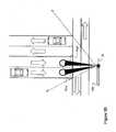
Figs. 3A and3B . In this case, the light source 61 (i.e., that corresponds to thelight source 12 in thetraffic light unit 10B) illuminates the same scene enclosing objects A through D, but typically onediscrete detector 16 having a narrow field of view FOV is used in combination with ascanning mechanism 63. Thescanning mechanism 63 changes the portion of the illuminated volume being probed by the detector, in essence changing the field of view FOV to FOV'. Again,detector 16 might be any of a photodiode, an APD, a PMT or equivalent thereof. This configuration minimizes the number of components but requires sequential probing of the illuminated volume and the use of a mobile part in thescanning mechanism 63. Moreover, a motion of thescanning mechanism 63 must be actuated and monitored by the data/signal processor 18 as the orientation of thescanning mechanism 63 will have an effect on the calculation of the position of the objects. Referring toFig. 3B , the sensor configuration with thescanning mechanism 63 is illustrated detecting the presence of vehicles on the road. - In another alternative embodiment, illustrated in
Fig. 4 , a detection array 72 (i.e., that corresponds to thedetector 16 in thetraffic light unit 10B) is used with a large field of view FOVM encompassing the whole illuminated scene as illuminated by light source 71 (i.e., that corresponds to thelight source 12 in thetraffic light unit 10B). Each pixel of thearray 72 acts as a discrete detector with a very narrow field of view and probes a specific portion of the illuminated scene, as determined by any secondary optics in front of the array. Thearray 72 is any linear or 2D-type array, such as APD or photodiode arrays, CCD and CMOS sensors. CMOS sensors with fast electronic shutter are particularly efficient. - Another alternative embodiment presented in
Fig. 5 transfers to the source side the need to select a field of detection from within the field of illumination. In this embodiment, the light source is composed of multiple individual lighting elements (e.g., LEDs or small clusters of LEDs) that are driven together by the illumination drive signal (without modulation), providing constant illumination of the scene. Alens 82 is used to alter the emitted light, andsensor 81 detects the input light signal. - Using a sequencing component within the source controller, each
lighting element light element 83 illuminates only a portion of the scene with a narrow field of view FOVS, as determined by the appropriately designed secondary optics, while the other elements (e.g., 84) are fed by the illumination drive signal only, illuminating the rest of the scene without modulation. - After the specified duration, another element (e.g., 84) is switched to modulated mode and the
initial element 83 falls back to the illumination drive signal only. This operation is repeated according to programming of the data/signal processor 18, which controls drive sequencing (as shown inFig. 1 ). In essence, the modulated or pulsed light emission is being scanned in discrete steps in the illuminated spatial volume. - In such a configuration,
discrete detector 81 with a large field of view FOVL encompassing the entire illuminated scene will be sensitive only to objects within FOVS. Thediscrete detector 81 may be any of a photodiode, an APD, a PMT or equivalent thereof. This configuration is well adapted for applications where the light source is or can be a group of lighting elements and simplifies the detection stage design, at the price of possible lower brightness of the modulated or pulsed source, more sophisticated design of the secondary source optics and sequential probing of the spatial volume of interest. - In
Fig. 6 , there is illustrated a calibration of thelighting system 10. In such calibration, the limits of the field of view of thedetector 16 are associated with a distance from thetraffic light unit 10B, so as to calibrate thedetector 16. As an example, information may be entered using a user interface of the data/signal processor 18. The calibration is used to ensure that thelighting system 10 covers a desired region, for instance by adjusting the coverage to the width of the road. Moreover, the calibration will ensure that the position of the stop lines are known, as the actions of thelighting system 10 may have an effect on the stopping of vehicles. - The
system 10 can be used as a road weather information system (RWIS) and thus provide information about temperature, visibility (fog, snow, rain), condition of the road (icy) and pollution (smog). Thesystem 10 can be used to adjust the intensity of light depending on weather conditions. - Traffic lights are lighting applications that currently use LEDs as a light source. In this case, the increased irradiance, lifetime, switching time and efficiency are beneficial to the application. In this latter case, an improvement would be to add the features of the
lighting system 10 to these lights by designing/retrofitting the lights with the various components of thelighting system 10, rather than to use inductive or capacitive sensors placed into the ground under the road pavement. - In the case of prior art traffic lights with detection capabilities, sensors are placed under the pavement. Then, when a vehicle arrives at road crossings, it is detected (by electrical induction or capacitive sensing) and the traffic lights are activated with predetermined timing settings. However, to place these sensors under the pavement requires excavation work to be performed for each road crossing.
- With such sensors, the detection occurs only at the level of the sensors, so the speed and the number of cars cannot readily be estimated. The features of the
lighting system 10 would allow further intelligence to be implemented into the traffic light systems, and thus more possibility of lowering the risk of car accidents. - Using an optical detector to detect cars beneath, within or adjacent to the
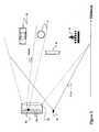
traffic light units 10B, as proposed by thelighting system 10, would allow cost-efficient detection, since the pavement would not need to be removed to put the detector into place. Moreover, it is considered to combine the detection of a street light (or other lighting system) to a signaling action with a traffic light. Referring toFig. 7 , astreet light 90 is shown, and incorporates the components of thelighting system 10 ofFig. 1 . As such, thestreet light 90 is adapted to detect the presence of objects, such as vehicles as is illustrated inFig. 7 . - Therefore, upon detecting a vehicle, the
street light 90 signals the detection to the external system B (Fig. 1 ). The external system B forwards the information or commands to an appropriate traffic light, to control the emission of signals. - Maintenance and repairs would also be less costly. Furthermore, using multiple detectors having different fields of view would allow detection of many vehicles at the same time, as well as evaluation of their speed in the same lane or in separate lanes, making it a useful tool for traffic measurement and control.
- The speed of the vehicles could also be measured with the modulation phase shift measurement (or time of flight of pulsed light with continuous detection signal) technique described previously.
- The visibility changes in different weather conditions could also be measured. In fact, the yellow signal lights seen along roads in the vicinity of rivers to signal poor visibility conditions caused by fog could be used as visible-light sources that would allow such visibility to be measured with proper detection. The
lighting system 10 could be used to detect an encoded light source placed on emergency vehicles (that could be the vehicle emergency lights themselves if based on LEDs) having a specific modulation scheme allowing a signal to be sent to the traffic lights to make them turn green in their favor. Theoptical detector 16 of thelighting system 10 can be used to detect an encoded incoming light signal from external (or other) light sources such as a remote control that would allow communication in order to control, calibrate or configure the lighting unit for the current location and usage requirements. - The measurement of vehicle speed is also possible either by distance measurement or by measurement of their time of passage at different points along the street lane beneath the LED street-lighting devices. This makes possible gathering of information that would not otherwise be possible, without installing special devices or sensors.
- It is considered to implement spectroscopic detection at two (or more) different wavelengths of gas emission from vehicles or other sources in the vicinity of the streetlights (for homeland security issues). The different wavelengths would then allow detection (with two detectors detecting different wavelengths) of a difference in signals from either different absorption or diffusion levels from gases. Here again, the visibility changes in different weather conditions could also be measured.
- For luminaires or.streetlights based on LEDs, the same type of possibility could be implemented, through the use of already installed lighting, allowing the detection of the presence of individuals or vehicles beneath the lights in order to control the light level accordingly. When no circulation is detected, the light level can be lowered to decrease the energy required.
- In fact,
traffic light units 10B streetlights, rail lights, and parking meters equipped with the detection capabilities provided by thelighting system 10 could be the base of a network allowing to manage traffic and vehicle circulation inside cities and emergency situations having impacts on traffic. This could be made possible by putting their data/signal processing units 18 in communication with a central external traffic managing system (i.e., external system B ofFig. 1 ) through RF links or through power lines. - Energy consumption is an increasing concern because of the rising costs of energy. Efficient street lighting power consumption, and thus energy budgets of cities, will benefit from LEDs when they reach this application. Controlling the light level is readily achieved with LEDs compared to current sodium luminaires which have a restrike time in the order of minutes. Thus, with LEDs it becomes feasible to control streetlight level when no civilians are circulating under these lights, and this also allows energy savings.
- Current street-lighting systems do not allow the adjustment of light level on demand which would readily be performed using the
lighting system 10. Such adjustment capability would allow a decrease in their energy consumption. For example, sodium lights can hardly be adjusted in intensity. Usually, no detection systems are present, or they are based on movement detection sensors, which are usually based on infrared detectors that can hardly detect moving people or vehicles at hot ambient temperatures or people covered in winter clothes in cold weather. - Furthermore, such detectors work better at short range and with a limited field of view and, since many streetlights are placed on long posts, they would suffer many calibration problems for that application. Even if streetlights were to show characteristics allowing them to be adjusted in intensity on demand, this would probably be one reason why such detectors would not be placed on streetlights. An adapted detector would need to cover a large field of view, not being sensitive only to heat difference, but being sensitive enough inside the field of view to detect as well pedestrians and trucks. Finally, it would also need to be technologically available and integrated at low costs.
- Lighting system with traffic management capabilities offer the possibility of providing the typical information for a management system (Count, speed, presence, occupancy, classification) and road weather information (visibility in bad weather could also be estimated through light-diffusion measurements on snow, fog, dust or rain). Police or governmental vehicles could even be equipped with more capable detection systems to detect cars with bad gas emissions causing pollution problems.
- Other applications are tunnel lighting (energy saving), traffic sign with lighting device, stop sign for instance (warming signal).
Claims (17)
- A method for controlling traffic signaling, comprising:providing a traffic light (10B) with a visible-light source (12) emitting visible light and having a function of actuating alternately at least two different traffic signal states for traffic signaling;driving the visible-light source (12) to emit light in a traffic signal state in a predetermined mode, with visible light in the predetermined mode being emitted so as to be visible to an unaided human eye;receiving a reflection/backscatter of the emitted visible light from an object (A);identifying at least one of a presence and a position of the object (A) as a function of the reflection/backscafter received and of the predetermined mode; andcontrolling said traffic signal states actuated by the visible-light source (12) as a function of the at least one of the presence and the position of the object (A),wherein driving the visible-light source (12) in the predetermined mode comprises at least one of pulsating and modulating the visible light, andwherein said visible-light source (12) comprises a light emitting diode (LED) light source.
- The method according to claim 1, wherein receiving the reflection/backscatter comprises filtering given light wavelengths.
- The method according to claim 1, wherein identifying at least one of a presence and a position of the object (A) comprises calculating at least a distance of the object (A) by measuring a time delay between emitting the visible light and receiving the reflection/backscatter from the object (A).
- The method according to claim 3, wherein calculating the distance comprises continuously calculating the distance so as to calculate a speed of the object (A).
- The method according to any one of claims 1 to 4, further comprising:providing an auxiliary light source (22) in association with the traffic light (10B);driving the auxiliary light source (22) concurrently with the visible-light source (12) in another predetermined mode to emit auxiliary light;receiving a reflection/backscatter of the auxiliary light from an object(A);identifying at least one of the presence and the position of the object (A) as a function of at least the reflection/backscatter received from the auxiliary light and the predetermined modes; andcontrolling said signal states actuated by the visible-light source (12) as a function of at least one of the presence and the position of the object (A).
- The method according to claim 5 wherein driving the auxiliary light source (22) comprises driving the auxiliary light source (22) into emitting light non-visible to an unaided human eye.
- The method according to any one of claims 1 to 6, wherein driving the visible-light source (12) to emit visible light in a predetermined mode comprises pulsating said light emission diode to produce light pulses having a width of less than 50 ns.
- The method according to any one of claims 1 to 7, wherein controlling said traffic signal states comprises switching said traffic signal states as a function of the at least one of the presence and the position of the object (A).
- A traffic-signal lighting system (10) comprising:a light source (12) emitting visible light and having a function of emitting visible light in an illumination mode for actuating alternately at least two traffic signal states;a source controller (14) for driving the light source into emitting one of the traffic signal states in a predetermined mode with visible light in the predetermined mode being emitted such that the light source maintains said function of emitting traffic signals visible to an unaided human eye in the environment while being driven by the source controller (14);an optical detector (16) adapted to detect the visible light as reflected/backscattered by an object (A) to produce detection data; anda data/signal processor (18) for receiving detection data from the optical detector (16), the data/signal processor (18) producing a data output associated to the object (A) as a function of the predetermined mode and the detection data, and for commanding the light source (12) into controlling said traffic signal states as a function of the data output,wherein the source controller (14) comprises a pulse/modulation driver (14B) to drive the visible-light source (12) in the predetermined mode and an illumination driver (14A) to drive the light source (12) into emitting light of suitable intensity to illuminate an environment, and wherein said light source (12) comprises a light emitting diode (LED) light source.
- The traffic-signal lighting system (10) according to claim 9, further comprising an external traffic-management system (B) connected to the data/signal processor (18) for managing traffic as a function of the detection data received from the data/signal processor (18).
- The traffic-signal lighting system (10) according to claim 9, wherein the optical detector (16) comprises a plurality of sub-detectors (16A-D) each detecting a specific zone.
- The traffic-signal lighting system (10) according to claim 9, further comprising a scanning mechanism (63) in association with the optical detector (16) so as to cause a scanning motion of a field of view (FOV) of the optical detector (16) within a range of illumination of emitted light of the light sources.
- The traffic-signal lighting system (10) according to claim 12, wherein the light source has a plurality of lights (83, 84), with at least one of the lights (84) of the light source being driven by the illumination driver (14A) to illuminate the environment, while at least another one of the lights (83) of the light source is driven by the pulse/modulation driver (14B) to emit the visible light in the predetermined mode.
- The traffic-signal lighting system (10) according to claim 9, further comprising an auxiliary light source (22) for emitting an auxiliary light in another predetermined mode concurrently with the visible-light source (12), the reflection/backscatter of the auxiliary light received from an object (A) being used to produce said data output associated to the object.
- The traffic-signal lighting system (10) according to claim 14, wherein the auxiliary light source (22) comprises a non-visible light source.
- The traffic-signal lighting system (10) according to claim 9, comprising:
an auxiliary light source (22) that is a non-visible light source emitting light non-visible to an unaided human eye. - The traffic-signal lighting system (10) according to claim 16, wherein said light backscattered by said object (A) is a backscatter from light emitted by said auxiliary light source (22).
Applications Claiming Priority (2)
| Application Number | Priority Date | Filing Date | Title |
|---|---|---|---|
| US94465807P | 2007-06-18 | 2007-06-18 | |
| PCT/CA2008/001161WO2008154737A1 (en) | 2007-06-18 | 2008-06-18 | Lighting system with traffic management capabilities |
Publications (3)
| Publication Number | Publication Date |
|---|---|
| EP2158579A1 EP2158579A1 (en) | 2010-03-03 |
| EP2158579A4 EP2158579A4 (en) | 2013-10-09 |
| EP2158579B1true EP2158579B1 (en) | 2014-10-15 |
Family
ID=40155841
Family Applications (1)
| Application Number | Title | Priority Date | Filing Date |
|---|---|---|---|
| EP08772824.2AActiveEP2158579B1 (en) | 2007-06-18 | 2008-06-18 | Lighting system with traffic management capabilities |
Country Status (4)
| Country | Link |
|---|---|
| US (1) | US8436748B2 (en) |
| EP (1) | EP2158579B1 (en) |
| CA (1) | CA2691141C (en) |
| WO (1) | WO2008154737A1 (en) |
Families Citing this family (35)
| Publication number | Priority date | Publication date | Assignee | Title |
|---|---|---|---|---|
| WO2008154736A1 (en)* | 2007-06-18 | 2008-12-24 | Leddartech Inc. | Lighting system with driver assistance capabilities |
| US8242476B2 (en) | 2005-12-19 | 2012-08-14 | Leddartech Inc. | LED object detection system and method combining complete reflection traces from individual narrow field-of-view channels |
| EP2158579B1 (en) | 2007-06-18 | 2014-10-15 | Leddartech Inc. | Lighting system with traffic management capabilities |
| EP2235561B8 (en) | 2007-12-21 | 2017-05-31 | Leddartech Inc. | Detection and ranging methods and systems |
| US8723689B2 (en)* | 2007-12-21 | 2014-05-13 | Leddartech Inc. | Parking management system and method using lighting system |
| KR101738013B1 (en)* | 2008-06-10 | 2017-05-19 | 엑스트랄리스 테크놀로지 리미티드 | Particle detection |
| ITMO20090210A1 (en)* | 2009-08-07 | 2011-02-08 | Zetech S R L | ROAD SIGNALING SYSTEM |
| US20120218107A1 (en) | 2009-12-14 | 2012-08-30 | Yvan Mimeault | Entity detection system and method for monitoring an area |
| CN102959599B (en) | 2009-12-22 | 2015-07-15 | 莱达科技股份有限公司 | Active 3D monitoring system for traffic detection |
| CA2802487C (en) | 2010-07-23 | 2016-06-28 | Leddartech Inc. | 3d optical detection system and method for a mobile storage system |
| TW201208477A (en)* | 2010-08-02 | 2012-02-16 | Hon Hai Prec Ind Co Ltd | Smart street lamp controlling system and the controlling method thereof |
| EP2434311B1 (en)* | 2010-09-27 | 2014-07-16 | Sick Ag | Method for optical monitoring of a surveillance area and reflection light probe |
| US8908159B2 (en) | 2011-05-11 | 2014-12-09 | Leddartech Inc. | Multiple-field-of-view scannerless optical rangefinder in high ambient background light |
| DE102011076123A1 (en) | 2011-05-19 | 2012-11-22 | Siemens Ag | Light signal device and method for determining the degree of contamination of a lens of a signal generator |
| EP2721593B1 (en) | 2011-06-17 | 2017-04-05 | Leddartech Inc. | System and method for traffic side detection and characterization |
| CN102324186B (en)* | 2011-09-13 | 2013-05-22 | 大连海事大学 | A method for calculating the passing time of vehicles at signal light intersections |
| EP2781922A4 (en) | 2011-11-14 | 2015-04-08 | Fujitsu Ltd | ELECTRONIC APPARATUS, PORTABLE TERMINAL AND METHOD OF MEASURING SPEED |
| CA2865733C (en) | 2012-03-02 | 2023-09-26 | Leddartech Inc. | System and method for multipurpose traffic detection and characterization |
| US10509101B2 (en) | 2013-11-21 | 2019-12-17 | General Electric Company | Street lighting communications, control, and special services |
| US9420674B2 (en) | 2013-11-21 | 2016-08-16 | General Electric Company | System and method for monitoring street lighting luminaires |
| US9621265B2 (en) | 2013-11-21 | 2017-04-11 | General Electric Company | Street lighting control, monitoring, and data transportation system and method |
| US9622323B2 (en) | 2013-11-21 | 2017-04-11 | General Electric Company | Luminaire associate |
| US9646495B2 (en) | 2013-11-21 | 2017-05-09 | General Electric Company | Method and system for traffic flow reporting, forecasting, and planning |
| WO2015128192A1 (en)* | 2014-02-26 | 2015-09-03 | Koninklijke Philips N.V. | Light reflectance based detection |
| JP6938371B2 (en) | 2014-09-09 | 2021-09-22 | レッダーテック インコーポレイテッド | Discretization of detection zones |
| WO2016059499A1 (en) | 2014-10-17 | 2016-04-21 | Philips Lighting Holding B.V. | System and method for outdoor lighting operation and management using its protocols and connectivity infrastructure. |
| EP3113157B1 (en)* | 2015-06-30 | 2019-05-22 | Harman Professional Denmark ApS | Light fixture with infrared light beam and with visible light beam |
| ITUB20154173A1 (en)* | 2015-10-01 | 2017-04-01 | Datalogic IP Tech Srl | Optoelectronic sensor and operating method of an optoelectronic sensor |
| DE112015006923T5 (en)* | 2015-10-21 | 2018-05-30 | Ford Global Technologies, Llc | Lighting system for trunk roads |
| US9648701B1 (en) | 2015-12-31 | 2017-05-09 | General Electric Company | Multi-functional optical sensor for indoor lighting systems |
| US20170372602A1 (en)* | 2016-06-24 | 2017-12-28 | Continental Advanced Lidar Solutions Us, Llc | Ladar enabled traffic control |
| US20180089999A1 (en)* | 2016-09-29 | 2018-03-29 | Peter Zal | Highway Traffic Control Device |
| CN108631868A (en)* | 2018-03-07 | 2018-10-09 | 华南理工大学 | A kind of dynamic testing method and its system for dynamic visible light communication |
| US11892572B1 (en) | 2020-12-30 | 2024-02-06 | Waymo Llc | Spatial light modulator retroreflector mitigation |
| US11887475B1 (en) | 2021-12-13 | 2024-01-30 | Ford Global Technologies, Llc | Systems and methods for controlling a programmable traffic light |
Family Cites Families (172)
| Publication number | Priority date | Publication date | Assignee | Title |
|---|---|---|---|---|
| DE2002012A1 (en) | 1969-01-21 | 1970-08-13 | Del Signore Dr Giovanni | Device and method for reporting obstacles and for displaying the distance of the obstacles |
| US4717862A (en) | 1984-11-19 | 1988-01-05 | The United States Government As Represented By The Secretary Of The Navy | Pulsed illumination projector |
| US4891624A (en) | 1987-06-12 | 1990-01-02 | Stanley Electric Co., Ltd. | Rearward vehicle obstruction detector using modulated light from the brake light elements |
| US4908615A (en)* | 1987-06-26 | 1990-03-13 | Texas Instruments Incorporated | Traffic light control system and method |
| GB8727824D0 (en) | 1987-11-27 | 1987-12-31 | Combustion Dev Ltd | Monitoring means |
| GB8826624D0 (en) | 1988-11-14 | 1988-12-21 | Martell D K | Traffic congestion monitoring system |
| US4928232A (en) | 1988-12-16 | 1990-05-22 | Laser Precision Corporation | Signal averaging for optical time domain relectometers |
| US5134393A (en) | 1990-04-02 | 1992-07-28 | Henson H Keith | Traffic control system |
| EP0476562A3 (en) | 1990-09-19 | 1993-02-10 | Hitachi, Ltd. | Method and apparatus for controlling moving body and facilities |
| US5179286A (en) | 1990-10-05 | 1993-01-12 | Mitsubishi Denki K.K. | Distance measuring apparatus receiving echo light pulses |
| FR2671653B1 (en) | 1991-01-11 | 1995-05-24 | Renault | MOTOR VEHICLE TRAFFIC MEASUREMENT SYSTEM. |
| US5357331A (en) | 1991-07-02 | 1994-10-18 | Flockencier Stuart W | System for processing reflected energy signals |
| US5102218A (en) | 1991-08-15 | 1992-04-07 | The United States Of America As Represented By The Secretary Of The Air Force | Target-aerosol discrimination by means of digital signal processing |
| GB2264411B (en) | 1992-02-13 | 1995-09-06 | Roke Manor Research | Active infrared detector system |
| FR2690519B1 (en) | 1992-04-23 | 1994-06-10 | Est Centre Etu Tech Equipement | DEVICE FOR ANALYZING THE PATH OF MOBILES. |
| US5546188A (en) | 1992-11-23 | 1996-08-13 | Schwartz Electro-Optics, Inc. | Intelligent vehicle highway system sensor and method |
| DE4304298A1 (en) | 1993-02-15 | 1994-08-18 | Atlas Elektronik Gmbh | Method for classifying vehicles passing a given waypoint |
| US5510800A (en) | 1993-04-12 | 1996-04-23 | The Regents Of The University Of California | Time-of-flight radio location system |
| US5389921A (en) | 1993-05-17 | 1995-02-14 | Whitton; John M. | Parking lot apparatus and method |
| US5381155A (en) | 1993-12-08 | 1995-01-10 | Gerber; Eliot S. | Vehicle speeding detection and identification |
| US5552767A (en) | 1994-02-14 | 1996-09-03 | Toman; John R. | Assembly for, and method of, detecting and signalling when an object enters a work zone |
| US5714754A (en) | 1994-03-04 | 1998-02-03 | Nicholas; John Jacob | Remote zone operation of lighting systems for above-ground enclosed or semi-enclosed parking structures |
| DE69409815T2 (en) | 1994-11-26 | 1998-08-13 | Hewlett Packard Gmbh | Optical time domain reflectometer and method for optical time domain reflectometry |
| US5633629A (en) | 1995-02-08 | 1997-05-27 | Hochstein; Peter A. | Traffic information system using light emitting diodes |
| DE19604338B4 (en) | 1995-02-18 | 2004-07-15 | Leich, Andreas, Dipl.-Ing. | Vehicle counting and classification device |
| US6259862B1 (en) | 1995-04-11 | 2001-07-10 | Eastman Kodak Company | Red-eye reduction using multiple function light source |
| DE19517001A1 (en) | 1995-05-09 | 1996-11-14 | Sick Optik Elektronik Erwin | Method and device for determining the light propagation time over a measuring section arranged between a measuring device and a reflecting object |
| US5764163A (en) | 1995-09-21 | 1998-06-09 | Electronics & Space Corp. | Non-imaging electro-optic vehicle sensor apparatus utilizing variance in reflectance |
| JP3206414B2 (en) | 1996-01-10 | 2001-09-10 | トヨタ自動車株式会社 | Vehicle type identification device |
| JP3379324B2 (en) | 1996-02-08 | 2003-02-24 | トヨタ自動車株式会社 | Moving object detection method and apparatus |
| ES2153159T3 (en) | 1996-03-25 | 2001-02-16 | Mannesmann Ag | PROCEDURE AND SYSTEM FOR THE REGISTRATION OF TRAFFIC SITUATION THROUGH A STATIONAL SYSTEM OF DATA REGISTRATION. |
| WO1997037242A1 (en) | 1996-04-01 | 1997-10-09 | Gatsometer B.V. | Method and apparatus for determining the speed and location of a vehicle |
| US5838116A (en) | 1996-04-15 | 1998-11-17 | Jrs Technology, Inc. | Fluorescent light ballast with information transmission circuitry |
| US5760887A (en) | 1996-04-30 | 1998-06-02 | Hughes Electronics | Multi-pulse, multi-return, modal range processing for clutter rejection |
| US5777564A (en)* | 1996-06-06 | 1998-07-07 | Jones; Edward L. | Traffic signal system and method |
| IT1286684B1 (en) | 1996-07-26 | 1998-07-15 | Paolo Sodi | DEVICE AND METHOD FOR DETECTION OF ROAD INFRINGEMENTS WITH DYNAMIC POINTING SYSTEMS |
| US20030154017A1 (en) | 1996-09-25 | 2003-08-14 | Ellis Christ G. | Apparatus and method for vehicle counting, tracking and tagging |
| US20040083035A1 (en) | 1996-09-25 | 2004-04-29 | Ellis Christ G. | Apparatus and method for automatic vision enhancement in a traffic complex |
| US5812249A (en) | 1996-09-26 | 1998-09-22 | Envirotest Systems Corporation | Speed and acceleration monitoring device using visible laser beams |
| DE19643475C1 (en) | 1996-10-22 | 1998-06-25 | Laser Applikationan Gmbh | Speed measurement method based on the laser Doppler principle |
| US5900826A (en)* | 1996-11-27 | 1999-05-04 | Farber; Gary J. | Remote controlled portable traffic signals |
| US20050169643A1 (en) | 1997-01-02 | 2005-08-04 | Franklin Philip G. | Method and apparatus for the zonal transmission of data using building lighting fixtures |
| DE19701803A1 (en) | 1997-01-20 | 1998-10-01 | Sick Ag | Light sensor with light transit time evaluation |
| US5995900A (en) | 1997-01-24 | 1999-11-30 | Grumman Corporation | Infrared traffic sensor with feature curve generation |
| HUP0000611A3 (en) | 1997-02-05 | 2000-07-28 | Siemens Ag | Motor vehicle detector |
| EP0866434B1 (en) | 1997-02-19 | 2004-06-16 | ATX Europe GmbH | Device to collect data about moving objects |
| DE19708014A1 (en) | 1997-02-27 | 1998-09-10 | Ernst Dr Hoerber | Device and method for detecting an object in a predetermined spatial area, in particular vehicles for traffic monitoring |
| US5942753A (en) | 1997-03-12 | 1999-08-24 | Remote Sensing Technologies | Infrared remote sensing device and system for checking vehicle brake condition |
| JP3281628B2 (en) | 1997-07-22 | 2002-05-13 | オート−センス リミテッド | Multi-frequency photoelectric detection system |
| US6548967B1 (en) | 1997-08-26 | 2003-04-15 | Color Kinetics, Inc. | Universal lighting network methods and systems |
| US5828320A (en) | 1997-09-26 | 1998-10-27 | Trigg Industries, Inc. | Vehicle overheight detector device and method |
| DE69821389T2 (en) | 1997-11-24 | 2004-09-16 | Peugeot Citroën Automobiles S.A. | SENSOR ARRANGEMENT WITH PHOTOCELLS |
| DE19804958A1 (en) | 1998-02-07 | 1999-08-12 | Itt Mfg Enterprises Inc | Evaluation concept for distance measuring methods |
| DE19804957A1 (en) | 1998-02-07 | 1999-08-12 | Itt Mfg Enterprises Inc | Distance measurement method with adaptive amplification |
| US6104314A (en) | 1998-02-10 | 2000-08-15 | Jiang; Jung-Jye | Automatic parking apparatus |
| US6404506B1 (en) | 1998-03-09 | 2002-06-11 | The Regents Of The University Of California | Non-intrusive laser-based system for detecting objects moving across a planar surface |
| DE19816004A1 (en) | 1998-04-09 | 1999-10-14 | Daimler Chrysler Ag | Arrangement for road condition detection |
| US6794831B2 (en) | 1998-04-15 | 2004-09-21 | Talking Lights Llc | Non-flickering illumination based communication |
| AT406093B (en) | 1998-05-19 | 2000-02-25 | Perger Andreas Dr | METHOD FOR OPTICAL DISTANCE MEASUREMENT |
| DE19823135A1 (en)* | 1998-05-23 | 1999-11-25 | Bosch Gmbh Robert | Traffic data acquisition for respective control of light signal system |
| US6044336A (en) | 1998-07-13 | 2000-03-28 | Multispec Corporation | Method and apparatus for situationally adaptive processing in echo-location systems operating in non-Gaussian environments |
| US6142702A (en) | 1998-11-25 | 2000-11-07 | Simmons; Jason | Parking space security and status indicator system |
| US6115113A (en) | 1998-12-02 | 2000-09-05 | Lockheed Martin Corporation | Method for increasing single-pulse range resolution |
| DE19856478C1 (en) | 1998-12-02 | 2000-06-21 | Ddg Ges Fuer Verkehrsdaten Mbh | Parking space detection |
| US6166645A (en) | 1999-01-13 | 2000-12-26 | Blaney; Kevin | Road surface friction detector and method for vehicles |
| US6771185B1 (en) | 1999-02-03 | 2004-08-03 | Chul Jin Yoo | Parking guidance and management system |
| US6107942A (en) | 1999-02-03 | 2000-08-22 | Premier Management Partners, Inc. | Parking guidance and management system |
| JP2002536739A (en) | 1999-02-05 | 2002-10-29 | ブレット・ホール | Parking lot facility computer management system |
| US6516286B1 (en) | 1999-04-06 | 2003-02-04 | Leica Geosystems Ag | Method for measuring the distance to at least one target |
| DE19919061A1 (en) | 1999-04-27 | 2000-11-02 | Robot Foto Electr Kg | Traffic monitoring device with polarization filters |
| DE19919925C2 (en) | 1999-04-30 | 2001-06-13 | Siemens Ag | Arrangement and method for the simultaneous measurement of the speed and the surface shape of moving objects |
| US6285297B1 (en) | 1999-05-03 | 2001-09-04 | Jay H. Ball | Determining the availability of parking spaces |
| GB2354898B (en) | 1999-07-07 | 2003-07-23 | Pearpoint Ltd | Vehicle licence plate imaging |
| US6502011B2 (en) | 1999-07-30 | 2002-12-31 | Gerhard Haag | Method and apparatus for presenting and managing information in an automated parking structure |
| US6946974B1 (en) | 1999-09-28 | 2005-09-20 | Racunas Jr Robert Vincent | Web-based systems and methods for internet communication of substantially real-time parking data |
| US6411204B1 (en) | 1999-11-15 | 2002-06-25 | Donnelly Corporation | Deceleration based anti-collision safety light control for vehicle |
| US6927700B1 (en) | 2000-01-04 | 2005-08-09 | Joseph P. Quinn | Method and apparatus for detection and remote notification of vehicle parking space availability data |
| US7123166B1 (en) | 2000-11-17 | 2006-10-17 | Haynes Michael N | Method for managing a parking lot |
| JP5138854B2 (en) | 2000-01-26 | 2013-02-06 | インストロ プレシジョン リミテッド | Optical distance measurement |
| US6147624A (en) | 2000-01-31 | 2000-11-14 | Intel Corporation | Method and apparatus for parking management system for locating available parking space |
| US6765495B1 (en) | 2000-06-07 | 2004-07-20 | Hrl Laboratories, Llc | Inter vehicle communication system |
| US6642854B2 (en) | 2000-06-14 | 2003-11-04 | Mcmaster Steven James | Electronic car park management system |
| DE10034976B4 (en) | 2000-07-13 | 2011-07-07 | iris-GmbH infrared & intelligent sensors, 12459 | Detecting device for detecting persons |
| JP2002059608A (en) | 2000-08-21 | 2002-02-26 | Olympus Optical Co Ltd | Printer |
| US7077319B2 (en) | 2000-11-24 | 2006-07-18 | Metrologic Instruments, Inc. | Imaging engine employing planar light illumination and linear imaging |
| US6665621B2 (en) | 2000-11-28 | 2003-12-16 | Scientific Technologies Incorporated | System and method for waveform processing |
| US6753766B2 (en) | 2001-01-15 | 2004-06-22 | 1138037 Ontario Ltd. (“Alirt”) | Detecting device and method of using same |
| JP2004528629A (en) | 2001-02-07 | 2004-09-16 | ビークルセンス, インク. | Parking management system |
| US6559776B2 (en) | 2001-02-15 | 2003-05-06 | Yoram Katz | Parking status control system and method |
| JP2002342896A (en) | 2001-05-21 | 2002-11-29 | Seiko Epson Corp | Parking Information System and Parking Information Program |
| US6426708B1 (en) | 2001-06-30 | 2002-07-30 | Koninklijke Philips Electronics N.V. | Smart parking advisor |
| ITBO20010571A1 (en) | 2001-09-20 | 2003-03-20 | Univ Bologna | VEHICLE TRAFFIC MONITORING SYSTEM AND CONTROL UNIT AND RELATED OPERATING METHOD |
| US6556916B2 (en) | 2001-09-27 | 2003-04-29 | Wavetronix Llc | System and method for identification of traffic lane positions |
| WO2003029046A1 (en) | 2001-10-03 | 2003-04-10 | Maryann Winter | Apparatus and method for sensing the occupancy status of parking spaces in a parking lot |
| KR100459475B1 (en) | 2002-04-04 | 2004-12-03 | 엘지산전 주식회사 | System and method for judge the kind of vehicle |
| US6885312B1 (en) | 2002-05-28 | 2005-04-26 | Bellsouth Intellectual Property Corporation | Method and system for mapping vehicle parking |
| US6783425B2 (en) | 2002-08-26 | 2004-08-31 | Shoot The Moon Products Ii, Llc | Single wire automatically navigated vehicle systems and methods for toy applications |
| JP3822154B2 (en) | 2002-09-12 | 2006-09-13 | 本田技研工業株式会社 | Vehicle detection device |
| US6842231B2 (en) | 2002-09-30 | 2005-01-11 | Raytheon Company | Method for improved range accuracy in laser range finders |
| US6825778B2 (en) | 2002-10-21 | 2004-11-30 | International Road Dynamics Inc. | Variable speed limit system |
| DE10251133B3 (en) | 2002-10-31 | 2004-07-29 | Gerd Reime | Device for controlling lighting, in particular for vehicle interiors, and method for controlling it |
| DE10252756A1 (en) | 2002-11-13 | 2004-05-27 | Robert Bosch Gmbh | A / D converter with improved resolution |
| US7426450B2 (en) | 2003-01-10 | 2008-09-16 | Wavetronix, Llc | Systems and methods for monitoring speed |
| US7148813B2 (en) | 2003-03-20 | 2006-12-12 | Gentex Corporation | Light emitting traffic sign having vehicle sensing capabilities |
| US7081832B2 (en) | 2003-04-25 | 2006-07-25 | General Electric Capital Corporation | Method and apparatus for obtaining data regarding a parking location |
| EP1623519A2 (en) | 2003-05-07 | 2006-02-08 | Koninklijke Philips Electronics N.V. | Communication system |
| FR2854692B1 (en) | 2003-05-07 | 2006-02-17 | Peugeot Citroen Automobiles Sa | OPTICAL EXPLORATION DEVICE AND VEHICLE COMPRISING SUCH A DEVICE |
| US20060145824A1 (en) | 2003-05-08 | 2006-07-06 | Henryk Frenzel | Method and device for detecting an object or a person |
| US6917307B2 (en) | 2003-05-08 | 2005-07-12 | Shih-Hsiung Li | Management method and system for a parking lot |
| PT1625664E (en) | 2003-05-22 | 2011-02-09 | Pips Technology Inc | Automated site security, monitoring and access control system |
| US7026954B2 (en) | 2003-06-10 | 2006-04-11 | Bellsouth Intellectual Property Corporation | Automated parking director systems and related methods |
| KR100464584B1 (en) | 2003-07-10 | 2005-01-03 | 에이앤디엔지니어링 주식회사 | Laser Rangefinder and method thereof |
| DE102004035856A1 (en) | 2003-08-14 | 2005-03-10 | Roland Bittner | Electrical auxiliary device for use in a traffic system, e.g. a traffic data collection system or traffic warning system, whereby the device is mounted at least partially in a mounting tube or pipe of existing infrastructure |
| US7821422B2 (en) | 2003-08-18 | 2010-10-26 | Light Vision Systems, Inc. | Traffic light signal system using radar-based target detection and tracking |
| MY147105A (en) | 2003-09-03 | 2012-10-31 | Stratech Systems Ltd | Apparatus and method for locating, identifying and tracking vehicles in a parking area |
| JP2005085187A (en) | 2003-09-11 | 2005-03-31 | Oki Electric Ind Co Ltd | Parking lot management system utilizing radio lan system |
| US7688222B2 (en) | 2003-09-18 | 2010-03-30 | Spot Devices, Inc. | Methods, systems and devices related to road mounted indicators for providing visual indications to approaching traffic |
| ITTO20030770A1 (en) | 2003-10-02 | 2005-04-03 | Fiat Ricerche | LONG-DETECTION DETECTOR LONG ONE |
| EP1522870B1 (en) | 2003-10-06 | 2013-07-17 | Triple-IN Holding AG | Distance measurement |
| US20050117364A1 (en) | 2003-10-27 | 2005-06-02 | Mark Rennick | Method and apparatus for projecting a turn signal indication |
| US7230545B2 (en) | 2003-11-07 | 2007-06-12 | Nattel Group, Inc. | Automobile communication and registry system |
| FR2864932B1 (en) | 2004-01-09 | 2007-03-16 | Valeo Vision | SYSTEM AND METHOD FOR DETECTING CIRCULATION CONDITIONS FOR A MOTOR VEHICLE |
| US20050187701A1 (en)* | 2004-02-23 | 2005-08-25 | Baney Douglas M. | Traffic communication system |
| JP2005290813A (en) | 2004-03-31 | 2005-10-20 | Honda Motor Co Ltd | Parking guidance robot |
| US7106214B2 (en) | 2004-04-06 | 2006-09-12 | Mongkol Jesadanont | Apparatus and method of finding an unoccupied parking space in a parking lot |
| JP4238766B2 (en) | 2004-04-15 | 2009-03-18 | 株式会社デンソー | Roundabout vehicle information system |
| US7323987B2 (en)* | 2004-06-28 | 2008-01-29 | Sigma Space Corporation | Compact single lens laser system for object/vehicle presence and speed determination |
| EP1628278A1 (en) | 2004-08-16 | 2006-02-22 | Alcatel | Method and system for detecting available parking places |
| US7405676B2 (en) | 2004-09-10 | 2008-07-29 | Gatsometer B.V. | Method and system for detecting with laser the passage by a vehicle of a point for monitoring on a road |
| JP2006133214A (en)* | 2004-10-04 | 2006-05-25 | Topcon Corp | Time difference measuring device, measuring method, distance measuring device and distance measuring method |
| KR20070065439A (en) | 2004-10-15 | 2007-06-22 | 트리코 프로덕츠 코포레이션 오브 테네시 | Object Detection System with VCSEL Diode Array |
| US7527207B2 (en) | 2004-12-01 | 2009-05-05 | Datalogic Scanning, Inc. | Triggering illumination for a data reader |
| JP2006172210A (en) | 2004-12-16 | 2006-06-29 | Matsushita Electric Works Ltd | Distance image sensor for vehicle, and obstacle monitoring device using the same |
| US7233683B2 (en) | 2005-01-04 | 2007-06-19 | Deere & Company | Method and system for guiding a vehicle with vision-based adjustment |
| US7610123B2 (en) | 2005-01-04 | 2009-10-27 | Deere & Company | Vision-aided system and method for guiding a vehicle |
| US7242281B2 (en) | 2005-02-23 | 2007-07-10 | Quintos Mel Francis P | Speed control system |
| ITTO20050138A1 (en) | 2005-03-04 | 2006-09-05 | Fiat Ricerche | EVALUATION SYSTEM OF THE FLUIDITY OF ROAD OR MOTORWAY TRAFFIC AND OF PREDICTION OF TAIL TRAINING AND SLOWDOWN |
| WO2006100672A2 (en) | 2005-03-21 | 2006-09-28 | Visonic Ltd. | Passive infra-red detectors |
| GB0506722D0 (en) | 2005-04-02 | 2005-05-11 | Agd Systems Ltd | Detector systems |
| US7768427B2 (en)* | 2005-08-05 | 2010-08-03 | Image Sensign Systems, Inc. | Processor architecture for traffic sensor and method for obtaining and processing traffic data using same |
| US20070069920A1 (en)* | 2005-09-23 | 2007-03-29 | A-Hamid Hakki | System and method for traffic related information display, traffic surveillance and control |
| US7714265B2 (en) | 2005-09-30 | 2010-05-11 | Apple Inc. | Integrated proximity sensor and light sensor |
| US7573400B2 (en)* | 2005-10-31 | 2009-08-11 | Wavetronix, Llc | Systems and methods for configuring intersection detection zones |
| GB2445767A (en) | 2005-11-24 | 2008-07-23 | Linda Long | Illuminated car park space indicator. |
| WO2008154736A1 (en) | 2007-06-18 | 2008-12-24 | Leddartech Inc. | Lighting system with driver assistance capabilities |
| US8242476B2 (en) | 2005-12-19 | 2012-08-14 | Leddartech Inc. | LED object detection system and method combining complete reflection traces from individual narrow field-of-view channels |
| EP1969395B1 (en) | 2005-12-19 | 2017-08-09 | Leddartech Inc. | Object-detecting lighting system and method |
| US7692136B2 (en) | 2006-02-20 | 2010-04-06 | Koninklijke Philips Electronics N.V. | Portable illumination device |
| ES2315078B1 (en) | 2006-03-06 | 2009-11-05 | Quality Informations System, S.A. | ESTIMATION SYSTEM FOR VEHICLE LOCATION IN PARKING. |
| ITTO20060214A1 (en) | 2006-03-22 | 2007-09-23 | Kria S R L | VEHICLE DETECTION SYSTEM |
| US7991542B2 (en) | 2006-03-24 | 2011-08-02 | Wavetronix Llc | Monitoring signalized traffic flow |
| DE102006025020B4 (en) | 2006-05-26 | 2017-02-09 | PMD Technologie GmbH | displacement measuring system |
| CA2664388C (en) | 2006-09-25 | 2014-12-30 | Tony Mayer | Micro-diffractive surveillance illuminator |
| US7642928B2 (en)* | 2006-12-20 | 2010-01-05 | M&K Hutchison Investments, Lp | Traffic signal with integrated sensors |
| US9460619B2 (en) | 2007-01-17 | 2016-10-04 | The Boeing Company | Methods and systems for controlling traffic flow |
| EP2158579B1 (en) | 2007-06-18 | 2014-10-15 | Leddartech Inc. | Lighting system with traffic management capabilities |
| US8319949B2 (en) | 2007-06-18 | 2012-11-27 | Leddartech Inc. | Method for detecting objects with visible light |
| IL184815A0 (en) | 2007-07-24 | 2008-11-03 | Elbit Systems Ltd | System and method for level of visibility determination and vehicle counting |
| US7640122B2 (en) | 2007-11-07 | 2009-12-29 | Institut National D'optique | Digital signal processing in optical systems used for ranging applications |
| US8723689B2 (en) | 2007-12-21 | 2014-05-13 | Leddartech Inc. | Parking management system and method using lighting system |
| EP2235561B8 (en) | 2007-12-21 | 2017-05-31 | Leddartech Inc. | Detection and ranging methods and systems |
| ES2330499B1 (en) | 2007-12-31 | 2010-09-21 | Imagsa Technologies, S.A. | PROCEDURE AND SYSTEM FOR DETECTION OF MOVING OBJECTS. |
| NL1035051C2 (en) | 2008-02-20 | 2009-08-24 | Markus Henricus Beuvink | Method, system and optical communication composition for obtaining traffic information. |
| US7554652B1 (en) | 2008-02-29 | 2009-06-30 | Institut National D'optique | Light-integrating rangefinding device and method |
| US8237791B2 (en) | 2008-03-19 | 2012-08-07 | Microsoft Corporation | Visualizing camera feeds on a map |
| DE202008003979U1 (en) | 2008-03-20 | 2008-06-26 | Fraas, Alfred, Dipl.-Ing. | Measuring system for traffic flow analysis |
| DE202008007078U1 (en) | 2008-05-26 | 2008-09-04 | Signalbau Huber Gmbh | Video detection with PMD sensors |
| US20090299633A1 (en) | 2008-05-29 | 2009-12-03 | Delphi Technologies, Inc. | Vehicle Pre-Impact Sensing System Having Terrain Normalization |
| JP5505761B2 (en) | 2008-06-18 | 2014-05-28 | 株式会社リコー | Imaging device |
| US7635854B1 (en) | 2008-07-09 | 2009-12-22 | Institut National D'optique | Method and apparatus for optical level sensing of agitated fluid surfaces |
| US8400511B2 (en) | 2009-12-04 | 2013-03-19 | Lockheed Martin Corporation | Optical detection and ranging sensor system for sense and avoid, and related methods |
| CN102959599B (en) | 2009-12-22 | 2015-07-15 | 莱达科技股份有限公司 | Active 3D monitoring system for traffic detection |
- 2008
- 2008-06-18EPEP08772824.2Apatent/EP2158579B1/enactiveActive
- 2008-06-18CACA2691141Apatent/CA2691141C/enactiveActive
- 2008-06-18USUS12/664,744patent/US8436748B2/enactiveActive
- 2008-06-18WOPCT/CA2008/001161patent/WO2008154737A1/enactiveApplication Filing
Also Published As
| Publication number | Publication date |
|---|---|
| EP2158579A4 (en) | 2013-10-09 |
| CA2691141A1 (en) | 2008-12-24 |
| US20100194595A1 (en) | 2010-08-05 |
| WO2008154737A1 (en) | 2008-12-24 |
| EP2158579A1 (en) | 2010-03-03 |
| US8436748B2 (en) | 2013-05-07 |
| CA2691141C (en) | 2013-11-26 |
Similar Documents
| Publication | Publication Date | Title |
|---|---|---|
| EP2158579B1 (en) | Lighting system with traffic management capabilities | |
| US7855376B2 (en) | Lighting system and method for illuminating and detecting object | |
| US8723689B2 (en) | Parking management system and method using lighting system | |
| EP3850916B1 (en) | Luminaire system for determining weather related information | |
| US8600656B2 (en) | Lighting system with driver assistance capabilities | |
| US8767215B2 (en) | Method for detecting objects with light | |
| US7273328B2 (en) | Emissive highway markers | |
| KR20180124249A (en) | Streetlight control device that automatically controls illumination according to surrounding circumstances information | |
| KR20210002663U (en) | colour temperature control register for street lamps | |
| KR102008684B1 (en) | Control system, and method thereof for led lighting | |
| KR101001013B1 (en) | How to control street lighting lighting using wireless signal | |
| KR20240024572A (en) | Smart crosswalk system having smart breaker | |
| KR200285411Y1 (en) | Car's Senser |
Legal Events
| Date | Code | Title | Description |
|---|---|---|---|
| PUAI | Public reference made under article 153(3) epc to a published international application that has entered the european phase | Free format text:ORIGINAL CODE: 0009012 | |
| 17P | Request for examination filed | Effective date:20091222 | |
| AK | Designated contracting states | Kind code of ref document:A1 Designated state(s):AT BE BG CH CY CZ DE DK EE ES FI FR GB GR HR HU IE IS IT LI LT LU LV MC MT NL NO PL PT RO SE SI SK TR | |
| AX | Request for extension of the european patent | Extension state:AL BA MK RS | |
| DAX | Request for extension of the european patent (deleted) | ||
| RAP1 | Party data changed (applicant data changed or rights of an application transferred) | Owner name:LEDDARTECH INC. | |
| RAP1 | Party data changed (applicant data changed or rights of an application transferred) | Owner name:LEDDARTECH INC. | |
| A4 | Supplementary search report drawn up and despatched | Effective date:20130910 | |
| RIC1 | Information provided on ipc code assigned before grant | Ipc:G01S 17/06 20060101ALI20130904BHEP Ipc:G08G 1/07 20060101AFI20130904BHEP Ipc:G08G 1/095 20060101ALI20130904BHEP Ipc:G08G 1/04 20060101ALI20130904BHEP | |
| GRAP | Despatch of communication of intention to grant a patent | Free format text:ORIGINAL CODE: EPIDOSNIGR1 | |
| RIC1 | Information provided on ipc code assigned before grant | Ipc:G01S 17/06 20060101ALI20140430BHEP Ipc:G08G 1/04 20060101ALI20140430BHEP Ipc:G08G 1/07 20060101AFI20140430BHEP Ipc:G08G 1/095 20060101ALI20140430BHEP | |
| INTG | Intention to grant announced | Effective date:20140526 | |
| GRAS | Grant fee paid | Free format text:ORIGINAL CODE: EPIDOSNIGR3 | |
| GRAA | (expected) grant | Free format text:ORIGINAL CODE: 0009210 | |
| AK | Designated contracting states | Kind code of ref document:B1 Designated state(s):AT BE BG CH CY CZ DE DK EE ES FI FR GB GR HR HU IE IS IT LI LT LU LV MC MT NL NO PL PT RO SE SI SK TR | |
| REG | Reference to a national code | Ref country code:CH Ref legal event code:EP Ref country code:GB Ref legal event code:FG4D | |
| REG | Reference to a national code | Ref country code:IE Ref legal event code:FG4D | |
| REG | Reference to a national code | Ref country code:AT Ref legal event code:REF Ref document number:691971 Country of ref document:AT Kind code of ref document:T Effective date:20141115 | |
| REG | Reference to a national code | Ref country code:DE Ref legal event code:R096 Ref document number:602008034914 Country of ref document:DE Effective date:20141127 | |
| REG | Reference to a national code | Ref country code:NL Ref legal event code:VDEP Effective date:20141015 | |
| REG | Reference to a national code | Ref country code:AT Ref legal event code:MK05 Ref document number:691971 Country of ref document:AT Kind code of ref document:T Effective date:20141015 | |
| REG | Reference to a national code | Ref country code:LT Ref legal event code:MG4D | |
| PG25 | Lapsed in a contracting state [announced via postgrant information from national office to epo] | Ref country code:NL Free format text:LAPSE BECAUSE OF FAILURE TO SUBMIT A TRANSLATION OF THE DESCRIPTION OR TO PAY THE FEE WITHIN THE PRESCRIBED TIME-LIMIT Effective date:20141015 | |
| PG25 | Lapsed in a contracting state [announced via postgrant information from national office to epo] | Ref country code:IS Free format text:LAPSE BECAUSE OF FAILURE TO SUBMIT A TRANSLATION OF THE DESCRIPTION OR TO PAY THE FEE WITHIN THE PRESCRIBED TIME-LIMIT Effective date:20150215 Ref country code:FI Free format text:LAPSE BECAUSE OF FAILURE TO SUBMIT A TRANSLATION OF THE DESCRIPTION OR TO PAY THE FEE WITHIN THE PRESCRIBED TIME-LIMIT Effective date:20141015 Ref country code:LT Free format text:LAPSE BECAUSE OF FAILURE TO SUBMIT A TRANSLATION OF THE DESCRIPTION OR TO PAY THE FEE WITHIN THE PRESCRIBED TIME-LIMIT Effective date:20141015 Ref country code:PT Free format text:LAPSE BECAUSE OF FAILURE TO SUBMIT A TRANSLATION OF THE DESCRIPTION OR TO PAY THE FEE WITHIN THE PRESCRIBED TIME-LIMIT Effective date:20150216 Ref country code:NO Free format text:LAPSE BECAUSE OF FAILURE TO SUBMIT A TRANSLATION OF THE DESCRIPTION OR TO PAY THE FEE WITHIN THE PRESCRIBED TIME-LIMIT Effective date:20150115 Ref country code:ES Free format text:LAPSE BECAUSE OF FAILURE TO SUBMIT A TRANSLATION OF THE DESCRIPTION OR TO PAY THE FEE WITHIN THE PRESCRIBED TIME-LIMIT Effective date:20141015 | |
| PG25 | Lapsed in a contracting state [announced via postgrant information from national office to epo] | Ref country code:GR Free format text:LAPSE BECAUSE OF FAILURE TO SUBMIT A TRANSLATION OF THE DESCRIPTION OR TO PAY THE FEE WITHIN THE PRESCRIBED TIME-LIMIT Effective date:20150116 Ref country code:AT Free format text:LAPSE BECAUSE OF FAILURE TO SUBMIT A TRANSLATION OF THE DESCRIPTION OR TO PAY THE FEE WITHIN THE PRESCRIBED TIME-LIMIT Effective date:20141015 Ref country code:CY Free format text:LAPSE BECAUSE OF FAILURE TO SUBMIT A TRANSLATION OF THE DESCRIPTION OR TO PAY THE FEE WITHIN THE PRESCRIBED TIME-LIMIT Effective date:20141015 Ref country code:LV Free format text:LAPSE BECAUSE OF FAILURE TO SUBMIT A TRANSLATION OF THE DESCRIPTION OR TO PAY THE FEE WITHIN THE PRESCRIBED TIME-LIMIT Effective date:20141015 Ref country code:SE Free format text:LAPSE BECAUSE OF FAILURE TO SUBMIT A TRANSLATION OF THE DESCRIPTION OR TO PAY THE FEE WITHIN THE PRESCRIBED TIME-LIMIT Effective date:20141015 Ref country code:PL Free format text:LAPSE BECAUSE OF FAILURE TO SUBMIT A TRANSLATION OF THE DESCRIPTION OR TO PAY THE FEE WITHIN THE PRESCRIBED TIME-LIMIT Effective date:20141015 Ref country code:HR Free format text:LAPSE BECAUSE OF FAILURE TO SUBMIT A TRANSLATION OF THE DESCRIPTION OR TO PAY THE FEE WITHIN THE PRESCRIBED TIME-LIMIT Effective date:20141015 | |
| REG | Reference to a national code | Ref country code:DE Ref legal event code:R097 Ref document number:602008034914 Country of ref document:DE | |
| PG25 | Lapsed in a contracting state [announced via postgrant information from national office to epo] | Ref country code:SK Free format text:LAPSE BECAUSE OF FAILURE TO SUBMIT A TRANSLATION OF THE DESCRIPTION OR TO PAY THE FEE WITHIN THE PRESCRIBED TIME-LIMIT Effective date:20141015 Ref country code:CZ Free format text:LAPSE BECAUSE OF FAILURE TO SUBMIT A TRANSLATION OF THE DESCRIPTION OR TO PAY THE FEE WITHIN THE PRESCRIBED TIME-LIMIT Effective date:20141015 Ref country code:DK Free format text:LAPSE BECAUSE OF FAILURE TO SUBMIT A TRANSLATION OF THE DESCRIPTION OR TO PAY THE FEE WITHIN THE PRESCRIBED TIME-LIMIT Effective date:20141015 Ref country code:RO Free format text:LAPSE BECAUSE OF FAILURE TO SUBMIT A TRANSLATION OF THE DESCRIPTION OR TO PAY THE FEE WITHIN THE PRESCRIBED TIME-LIMIT Effective date:20141015 Ref country code:EE Free format text:LAPSE BECAUSE OF FAILURE TO SUBMIT A TRANSLATION OF THE DESCRIPTION OR TO PAY THE FEE WITHIN THE PRESCRIBED TIME-LIMIT Effective date:20141015 | |
| PLBE | No opposition filed within time limit | Free format text:ORIGINAL CODE: 0009261 | |
| STAA | Information on the status of an ep patent application or granted ep patent | Free format text:STATUS: NO OPPOSITION FILED WITHIN TIME LIMIT | |
| PG25 | Lapsed in a contracting state [announced via postgrant information from national office to epo] | Ref country code:IT Free format text:LAPSE BECAUSE OF FAILURE TO SUBMIT A TRANSLATION OF THE DESCRIPTION OR TO PAY THE FEE WITHIN THE PRESCRIBED TIME-LIMIT Effective date:20141015 | |
| 26N | No opposition filed | Effective date:20150716 | |
| PG25 | Lapsed in a contracting state [announced via postgrant information from national office to epo] | Ref country code:MC Free format text:LAPSE BECAUSE OF FAILURE TO SUBMIT A TRANSLATION OF THE DESCRIPTION OR TO PAY THE FEE WITHIN THE PRESCRIBED TIME-LIMIT Effective date:20141015 | |
| REG | Reference to a national code | Ref country code:CH Ref legal event code:PL | |
| PG25 | Lapsed in a contracting state [announced via postgrant information from national office to epo] | Ref country code:SI Free format text:LAPSE BECAUSE OF FAILURE TO SUBMIT A TRANSLATION OF THE DESCRIPTION OR TO PAY THE FEE WITHIN THE PRESCRIBED TIME-LIMIT Effective date:20141015 Ref country code:LU Free format text:LAPSE BECAUSE OF FAILURE TO SUBMIT A TRANSLATION OF THE DESCRIPTION OR TO PAY THE FEE WITHIN THE PRESCRIBED TIME-LIMIT Effective date:20150618 | |
| REG | Reference to a national code | Ref country code:IE Ref legal event code:MM4A | |
| REG | Reference to a national code | Ref country code:FR Ref legal event code:PLFP Year of fee payment:9 | |
| PG25 | Lapsed in a contracting state [announced via postgrant information from national office to epo] | Ref country code:LI Free format text:LAPSE BECAUSE OF NON-PAYMENT OF DUE FEES Effective date:20150630 Ref country code:IE Free format text:LAPSE BECAUSE OF NON-PAYMENT OF DUE FEES Effective date:20150618 Ref country code:CH Free format text:LAPSE BECAUSE OF NON-PAYMENT OF DUE FEES Effective date:20150630 | |
| PG25 | Lapsed in a contracting state [announced via postgrant information from national office to epo] | Ref country code:MT Free format text:LAPSE BECAUSE OF FAILURE TO SUBMIT A TRANSLATION OF THE DESCRIPTION OR TO PAY THE FEE WITHIN THE PRESCRIBED TIME-LIMIT Effective date:20141015 | |
| REG | Reference to a national code | Ref country code:FR Ref legal event code:PLFP Year of fee payment:10 | |
| PG25 | Lapsed in a contracting state [announced via postgrant information from national office to epo] | Ref country code:HU Free format text:LAPSE BECAUSE OF FAILURE TO SUBMIT A TRANSLATION OF THE DESCRIPTION OR TO PAY THE FEE WITHIN THE PRESCRIBED TIME-LIMIT; INVALID AB INITIO Effective date:20080618 Ref country code:BG Free format text:LAPSE BECAUSE OF FAILURE TO SUBMIT A TRANSLATION OF THE DESCRIPTION OR TO PAY THE FEE WITHIN THE PRESCRIBED TIME-LIMIT Effective date:20141015 | |
| PG25 | Lapsed in a contracting state [announced via postgrant information from national office to epo] | Ref country code:TR Free format text:LAPSE BECAUSE OF FAILURE TO SUBMIT A TRANSLATION OF THE DESCRIPTION OR TO PAY THE FEE WITHIN THE PRESCRIBED TIME-LIMIT Effective date:20141015 | |
| PG25 | Lapsed in a contracting state [announced via postgrant information from national office to epo] | Ref country code:BE Free format text:LAPSE BECAUSE OF FAILURE TO SUBMIT A TRANSLATION OF THE DESCRIPTION OR TO PAY THE FEE WITHIN THE PRESCRIBED TIME-LIMIT Effective date:20141015 | |
| REG | Reference to a national code | Ref country code:FR Ref legal event code:CA Effective date:20171030 | |
| REG | Reference to a national code | Ref country code:FR Ref legal event code:PLFP Year of fee payment:11 | |
| PGFP | Annual fee paid to national office [announced via postgrant information from national office to epo] | Ref country code:GB Payment date:20240619 Year of fee payment:17 | |
| PGFP | Annual fee paid to national office [announced via postgrant information from national office to epo] | Ref country code:FR Payment date:20240627 Year of fee payment:17 | |
| PGFP | Annual fee paid to national office [announced via postgrant information from national office to epo] | Ref country code:DE Payment date:20240712 Year of fee payment:17 |