EP2157357B1 - Modular lighting system for recessed mounting in floor or wall - Google Patents
Modular lighting system for recessed mounting in floor or wallDownload PDFInfo
- Publication number
- EP2157357B1 EP2157357B1EP09010106AEP09010106AEP2157357B1EP 2157357 B1EP2157357 B1EP 2157357B1EP 09010106 AEP09010106 AEP 09010106AEP 09010106 AEP09010106 AEP 09010106AEP 2157357 B1EP2157357 B1EP 2157357B1
- Authority
- EP
- European Patent Office
- Prior art keywords
- module
- lighting
- lighting system
- modules
- constituted
- Prior art date
- Legal status (The legal status is an assumption and is not a legal conclusion. Google has not performed a legal analysis and makes no representation as to the accuracy of the status listed.)
- Active
Links
Images


Classifications
- F—MECHANICAL ENGINEERING; LIGHTING; HEATING; WEAPONS; BLASTING
- F21—LIGHTING
- F21V—FUNCTIONAL FEATURES OR DETAILS OF LIGHTING DEVICES OR SYSTEMS THEREOF; STRUCTURAL COMBINATIONS OF LIGHTING DEVICES WITH OTHER ARTICLES, NOT OTHERWISE PROVIDED FOR
- F21V15/00—Protecting lighting devices from damage
- F21V15/01—Housings, e.g. material or assembling of housing parts
- F—MECHANICAL ENGINEERING; LIGHTING; HEATING; WEAPONS; BLASTING
- F21—LIGHTING
- F21S—NON-PORTABLE LIGHTING DEVICES; SYSTEMS THEREOF; VEHICLE LIGHTING DEVICES SPECIALLY ADAPTED FOR VEHICLE EXTERIORS
- F21S2/00—Systems of lighting devices, not provided for in main groups F21S4/00 - F21S10/00 or F21S19/00, e.g. of modular construction
- F21S2/005—Systems of lighting devices, not provided for in main groups F21S4/00 - F21S10/00 or F21S19/00, e.g. of modular construction of modular construction
- F—MECHANICAL ENGINEERING; LIGHTING; HEATING; WEAPONS; BLASTING
- F21—LIGHTING
- F21S—NON-PORTABLE LIGHTING DEVICES; SYSTEMS THEREOF; VEHICLE LIGHTING DEVICES SPECIALLY ADAPTED FOR VEHICLE EXTERIORS
- F21S8/00—Lighting devices intended for fixed installation
- F21S8/02—Lighting devices intended for fixed installation of recess-mounted type, e.g. downlighters
- F21S8/022—Lighting devices intended for fixed installation of recess-mounted type, e.g. downlighters intended to be recessed in a floor or like ground surface, e.g. pavement or false floor
- F—MECHANICAL ENGINEERING; LIGHTING; HEATING; WEAPONS; BLASTING
- F21—LIGHTING
- F21S—NON-PORTABLE LIGHTING DEVICES; SYSTEMS THEREOF; VEHICLE LIGHTING DEVICES SPECIALLY ADAPTED FOR VEHICLE EXTERIORS
- F21S8/00—Lighting devices intended for fixed installation
- F21S8/02—Lighting devices intended for fixed installation of recess-mounted type, e.g. downlighters
- F21S8/024—Lighting devices intended for fixed installation of recess-mounted type, e.g. downlighters intended to be recessed in a wall or like vertical structure, e.g. building facade
- F—MECHANICAL ENGINEERING; LIGHTING; HEATING; WEAPONS; BLASTING
- F21—LIGHTING
- F21V—FUNCTIONAL FEATURES OR DETAILS OF LIGHTING DEVICES OR SYSTEMS THEREOF; STRUCTURAL COMBINATIONS OF LIGHTING DEVICES WITH OTHER ARTICLES, NOT OTHERWISE PROVIDED FOR
- F21V21/00—Supporting, suspending, or attaching arrangements for lighting devices; Hand grips
- F21V21/02—Wall, ceiling, or floor bases; Fixing pendants or arms to the bases
- F21V21/04—Recessed bases
- F—MECHANICAL ENGINEERING; LIGHTING; HEATING; WEAPONS; BLASTING
- F21—LIGHTING
- F21V—FUNCTIONAL FEATURES OR DETAILS OF LIGHTING DEVICES OR SYSTEMS THEREOF; STRUCTURAL COMBINATIONS OF LIGHTING DEVICES WITH OTHER ARTICLES, NOT OTHERWISE PROVIDED FOR
- F21V33/00—Structural combinations of lighting devices with other articles, not otherwise provided for
- F21V33/006—General building constructions or finishing work for buildings, e.g. roofs, gutters, stairs or floors; Garden equipment; Sunshades or parasols
Definitions
- the present inventionrelates to a lighting system for recessed mounting.
- Conventional lights for recessed mounting in walls and floorsare substantially constituted by an outer casing which accommodates the lighting devices, incandescent lamps, fluorescent lamps or, in the most recent products, LEDs.
- the minimum distance between two contiguous productsis, in the best of cases, the sum of the shoulders of the closing flanges of the devices.
- the closure flangesare not even adjacent.
- Conspicuous discontinuitiesare also evident in the points where a directional variation is present, typically at the corners.
- the conventional productsalso entail inventory and stock problems, because it is necessary to manage a rather large number of models of different dimensions in order to ensure a minimum of dimensional adaptability.
- DE-U-20101615discloses a lighting device constituted by an outer casing which enlcoses a lighting unit, according to the preamble of present claim 1.
- the aim of the present inventionis to provide a lighting system for recessed mounting for walls and floors that overcomes the drawbacks of the prior art.
- An object of the inventionis to provide a modular lighting system that is capable of providing a substantially continuous lighting, ensuring a lighting technology performance of high value.
- Another object of the inventionis to provide a lighting system that offers the possibility to vary the length of the product as a function of the requirements in a substantially linear manner, allowing to perfectly adapt the actually lit length with respect to the required length.
- a further objectis to provide a lighting system that allows to provide variations in the direction of the lighting system without interruptions in the continuity of the lighting.
- Another object of the inventionis to provide a lighting system that allows to adapt the outer casing according to the requirements, differently from currently commercially available products which have outer casings of a preset length which cannot be modified.
- Another object of the inventionis to provide a lighting system in which the minimum distance between two successive components is extremely reduced, so as to eliminate any aesthetic discontinuity of the product, which appears aesthetically identical over its entire length, even independently of variations in direction.
- Another object of the inventionis to provide a lighting system that allows extremely simpler management of the product in stock.
- Another important object of the inventionis to provide a lighting system that can be installed very easily and quickly.
- Another important object of the inventionis to provide a lighting system that is extremely versatile and allows to easily change the position of use of the product even when the product is already installed.
- Another object of the present inventionis to provide a lighting system which, by virtue of its particular constructive characteristics, is capable of giving the greatest assurances of reliability and safety in use.
- Another object of the present inventionis to provide a lighting system that can be manufactured easily by using commonly commercially available elements and materials and is also competitive from an economic standpoint.
- a lighting system for recessed mountingcomprising one or more outer casings that can be recessed in a wall or floor and one or more lighting devices, characterized in that the lighting devices are constituted by modular components that comprise single modules and multiple modules, said multiple modules being dimensionally multiples of a single module, said outer casings allowing mutual assembly in a modular fashion, each multiple module being constituted by a single body that is divided into sectors by means of easily breakable partitions, each sector corresponding dimensionally to said single module.
- the lighting system for recessed mounting according to the inventioncomprises one or more outer casings 2 that accommodate one or more lighting modules 3, 33.
- Each lighting modulecan be constituted by a single module 3 or by a multiple module 33, where the term “single” means a module that constitutes a basic unit and the term “multiple” means a module that is dimensionally a multiple of a single unit.
- the single module 3includes a single lighting component, in the specific case the LED 4, while the multiple module 33 includes a plurality of lighting components 4.
- the single module 3may in any case contain lighting units 4 that differ both in number and in type.
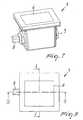
- the single module 3is constituted by a box 5, which is closed in an upper region by an at least partially transparent plate 6.
- the LED 4is associated with a supporting and wiring component 7, which is connected electrically to a male connector 8 and to a female connector 9.
- the connectors 8 and 9are arranged on the lateral portions of the box 5.
- the module 3comprises a reflector component 10, which is suitable to reflect the light emitted by the lighting unit 4 toward the transparent plate 6.
- An engagement component 11for example an elastic clip, is associated with the lower outer surface of the box 5 and is adapted to fix the module inside the outer casing 2.
- the multiple module 33is similar to the single module and includes an elongated box 55, which is closed in an upper region by a plate 66 that is at least partially transparent.
- the LEDs 4are associated with a supporting and wiring component 77, which is connected electrically to a male connector 8 and to a female connector 9.
- the connectors 8 and 9are arranged on the lateral portions of the box 55.
- the multiple module 33comprises a reflector component 110, which is suitable to reflect the light emitted by the lighting units 4 toward the transparent plate 66.
- the multiple module 33has a plurality of engagement components 11, which are associated with the lower outer surface of the box 55, in order to fix the module within the outer casing 2.
- An end module 103is substantially similar to a single or multiple module and further comprises a power supply connector 19, for supplying power to the entire system.
- a corner module 333which differs from the single module 3 in that it has the connectors 8 and 9 arranged on two adjacent sides instead of opposite sides, constitutes a direction changing unit, as shown schematically in Figures 1 , 2 and 11 .
- the outer casings 2are constituted by a single molded body, which is made of plastics and is divided into sectors 12 by means of easily breakable partitions 13, and can be assembled together according to the specific requirements.
- Each sector 12corresponds dimensionally to a single module 3 so that the outer casing 2 can be adapted to the number of single modules or to the dimensions of the multiple modules that one wishes to use.
- the systemalso comprises end components 14 to be applied to the free ends of the outer casing.
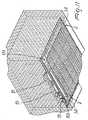
- Figures 1 , 2 and 11illustrate some examples of configuration of the modular lighting system according to the present invention.
- the installation of the systeminitially entails laying the outer casings 2, whose longitudinal extension can be adjusted easily by separating the excess sectors 12 by breaking the partitions 13 and/or by assembling multiple adjacent outer casings.
- the modulesare inserted and simply arranged side by side, in order to connect them electrically by means of the female and male connectors, locking them onto the bottom of the outer casing by means of the clips 11.
- the modular system of the present inventionsolves the problems of the prior art.
- the distance between contiguous modulesis so small that the center distance between the light sources within a module is maintained even in passing from one module to the next, without compromising luminous uniformity.
- Cornersdo not constitute points of discontinuity, because they maintain the characteristics cited above, allowing lighting even at the corner, by using an appropriately provided corner module 333 to be inserted in an appropriately provided outer corner casing that can be assembled together with the preceding ones.
- the electrical connection system of the lighting system according to the present inventionallows to limit the wiring operation to the first unit and to obtain sequentially the connection of all the other devices, simply by interlocking them successively.
- the arrangement of the modules within the outer casingcan be continuous, as shown in Figure 1 , or discontinuous, as shown schematically in Figure 2 , only at the objects that one wishes to light at that moment, covering any holes with the appropriately provided aesthetic modules.
- the lighting systemallows to vary the color of the light at a given point by simply choosing the suitable module, i.e., with a lighting unit 4 or transparent plate 6 of the chosen color.
- the lighting system according to the present inventionalso allows to adjust the luminous intensity, by means of a dimmer, of the entire line by acting only on the first module.
- the inventionachieves the intended aim and objects, a lighting system for recessed mounting having been provided which allows to obtain a practically continuous lighting while ensuring a lighting technology performance of great value with respect to the products of the prior art, which have evident discontinuities linked to the minimum distance between two successive lighting units.
- the lighting system according to the present inventionoffers the possibility to vary the length of the product according to the requirements in a substantially linear manner, in contrast to the conventional products known up to now, which by not being modular do not allow to adapt perfectly the length that is actually lit with respect to the required one.
- the lighting system according to the present inventionalso allows to provide variations in the direction of the product without interruptions in the continuity of the lighting, in contrast to hitherto known products, which have evident discontinuities in the points where it was necessary to ensure a directional passage.
- Another important advantage of the lighting system according to the present inventionis constituted by the possibility to adapt the dimensions of the outer casing to the specific requirements, in contrast to hitherto known products, which have outer casings of a preset and non-modifiable length.
- the lighting system according to the present inventionalso has the important advantage of being able to vary easily the distribution of the light, even when the product is already installed, simply by varying the position of the modules.
- the possibility to supply the modules after the first one by simply interlocking them, with consequent extremely easy assembly and speed in execution,is extremely advantageous both during first installation and subsequently, when one wishes to modify the lighting configuration.
- Another important advantage of the lighting system according to the present inventionis constituted by the simplified management of the product in stock, due to its extreme modularity, which allows to manage a minimal number of unit types.
Landscapes
- Engineering & Computer Science (AREA)
- General Engineering & Computer Science (AREA)
- Non-Portable Lighting Devices Or Systems Thereof (AREA)
- Arrangement Of Elements, Cooling, Sealing, Or The Like Of Lighting Devices (AREA)
Abstract
Description
- The present invention relates to a lighting system for recessed mounting.
- Conventional lights for recessed mounting in walls and floors are substantially constituted by an outer casing which accommodates the lighting devices, incandescent lamps, fluorescent lamps or, in the most recent products, LEDs.
- Currently commercially available products have outer casings of a preset length and therefore do not allow to perfectly adapt the length that is actually illuminated with respect to the required length.
- It is seldom possible to obtain a lighting structure that has the exact length of the surface to be illuminated: the product available from a catalog is often too long or too short and there are technological limitations to the manufacture of products beyond a certain length.
- Also, the minimum distance between two contiguous products is, in the best of cases, the sum of the shoulders of the closing flanges of the devices.
- In some cases, if the installation section of the outer casing is larger than the cross-section of the product, the closure flanges are not even adjacent.
- Conventional outdoor devices for recessed mounting in a wall/floor do not allow truly continuous lighting, because when several components are arranged side by side, conventional products show evident discontinuities caused by the minimum distance between two successive lighting units.
- Conspicuous discontinuities are also evident in the points where a directional variation is present, typically at the corners.
- The conventional products also entail inventory and stock problems, because it is necessary to manage a rather large number of models of different dimensions in order to ensure a minimum of dimensional adaptability.
- Another drawback of conventional recessed-mount systems is that it is not possible to easily vary the position of the light spots in order to concentrate or reduce lighting in preset positions, as instead would be desirable in some cases, for example in spaces designed for exhibitions and displays, where the position and dimensions of the objects to be lit vary as the exhibition event changes.
DE-U-20101615 discloses a lighting device constituted by an outer casing which enlcoses a lighting unit, according to the preamble ofpresent claim 1.- The aim of the present invention is to provide a lighting system for recessed mounting for walls and floors that overcomes the drawbacks of the prior art.
- An object of the invention is to provide a modular lighting system that is capable of providing a substantially continuous lighting, ensuring a lighting technology performance of high value.
- Another object of the invention is to provide a lighting system that offers the possibility to vary the length of the product as a function of the requirements in a substantially linear manner, allowing to perfectly adapt the actually lit length with respect to the required length.
- A further object is to provide a lighting system that allows to provide variations in the direction of the lighting system without interruptions in the continuity of the lighting.
- Another object of the invention is to provide a lighting system that allows to adapt the outer casing according to the requirements, differently from currently commercially available products which have outer casings of a preset length which cannot be modified.
- Another object of the invention is to provide a lighting system in which the minimum distance between two successive components is extremely reduced, so as to eliminate any aesthetic discontinuity of the product, which appears aesthetically identical over its entire length, even independently of variations in direction.
- Another object of the invention is to provide a lighting system that allows extremely simpler management of the product in stock.
- Another important object of the invention is to provide a lighting system that can be installed very easily and quickly.
- Another important object of the invention is to provide a lighting system that is extremely versatile and allows to easily change the position of use of the product even when the product is already installed.
- Another object of the present invention is to provide a lighting system which, by virtue of its particular constructive characteristics, is capable of giving the greatest assurances of reliability and safety in use.
- Another object of the present invention is to provide a lighting system that can be manufactured easily by using commonly commercially available elements and materials and is also competitive from an economic standpoint.
- This aim and these and other objects that will become better apparent hereinafter are achieved by a lighting system for recessed mounting, comprising one or more outer casings that can be recessed in a wall or floor and one or more lighting devices, characterized in that the lighting devices are constituted by modular components that comprise single modules and multiple modules, said multiple modules being dimensionally multiples of a single module, said outer casings allowing mutual assembly in a modular fashion, each multiple module being constituted by a single body that is divided into sectors by means of easily breakable partitions, each sector corresponding dimensionally to said single module.
- Further characteristics and advantages will become better apparent from the description of preferred but not exclusive embodiments of the invention, illustrated by way of non-limiting example in the accompanying drawings, wherein:
Figure 1 is a partially exploded perspective view of the lighting system for recessed mounting according to the present invention;Figure 2 is a perspective view, similar to the preceding one, of the system in a different configuration;Figure 3 is a plan view of a multiple module of the lighting system according to the present invention;Figure 4 is a perspective view of the multiple module of the preceding figure;Figure 5 is a longitudinal sectional view, taken along the sectional plane V-V ofFigure 3 , of the multiple module of the preceding figure;Figure 6 is a transverse sectional view, taken along the sectional plane VI-VI ofFigure 3 , of the multiple module of the preceding figure;Figure 7 is a perspective view of a single module of the lighting system according to the present invention;Figure 8 is a plan view of the single module of the preceding figure;Figure 9 is a longitudinal sectional view, taken along the sectional plane IX-IX ofFigure 8 , of the single module of the preceding figure;Figure 10 is a transverse sectional view, taken along the sectional plane X-X ofFigure 8 , of the single module of the preceding figure;Figure 11 is a perspective view of an implementation of the lighting system for recessed mounting according to the present invention.- With reference to the cited figures, the lighting system for recessed mounting according to the invention, generally designated by the
reference numeral 1, comprises one or moreouter casings 2 that accommodate one ormore lighting modules - Each lighting module can be constituted by a
single module 3 or by amultiple module 33, where the term "single" means a module that constitutes a basic unit and the term "multiple" means a module that is dimensionally a multiple of a single unit. - In the illustrated embodiment, the
single module 3 includes a single lighting component, in the specific case theLED 4, while themultiple module 33 includes a plurality oflighting components 4. - The
single module 3 may in any case containlighting units 4 that differ both in number and in type. - The
single module 3 is constituted by abox 5, which is closed in an upper region by an at least partiallytransparent plate 6. - The
LED 4 is associated with a supporting andwiring component 7, which is connected electrically to amale connector 8 and to afemale connector 9. - The
connectors box 5. - The
module 3 comprises areflector component 10, which is suitable to reflect the light emitted by thelighting unit 4 toward thetransparent plate 6. - An
engagement component 11, for example an elastic clip, is associated with the lower outer surface of thebox 5 and is adapted to fix the module inside theouter casing 2. - The
multiple module 33 is similar to the single module and includes anelongated box 55, which is closed in an upper region by aplate 66 that is at least partially transparent. - The
LEDs 4 are associated with a supporting andwiring component 77, which is connected electrically to amale connector 8 and to afemale connector 9. - The
connectors box 55. - The
multiple module 33 comprises areflector component 110, which is suitable to reflect the light emitted by thelighting units 4 toward thetransparent plate 66. - The
multiple module 33 has a plurality ofengagement components 11, which are associated with the lower outer surface of thebox 55, in order to fix the module within theouter casing 2. - An
end module 103 is substantially similar to a single or multiple module and further comprises apower supply connector 19, for supplying power to the entire system. - A
corner module 333, which differs from thesingle module 3 in that it has theconnectors Figures 1 ,2 and11 . - The
outer casings 2 are constituted by a single molded body, which is made of plastics and is divided intosectors 12 by means of easilybreakable partitions 13, and can be assembled together according to the specific requirements. - Each
sector 12 corresponds dimensionally to asingle module 3 so that theouter casing 2 can be adapted to the number of single modules or to the dimensions of the multiple modules that one wishes to use. - The system also comprises
end components 14 to be applied to the free ends of the outer casing. Figures 1 ,2 and11 illustrate some examples of configuration of the modular lighting system according to the present invention.- The installation of the system initially entails laying the
outer casings 2, whose longitudinal extension can be adjusted easily by separating theexcess sectors 12 by breaking thepartitions 13 and/or by assembling multiple adjacent outer casings. - Once the outer casings have been installed, the modules are inserted and simply arranged side by side, in order to connect them electrically by means of the female and male connectors, locking them onto the bottom of the outer casing by means of the
clips 11. - In order to allow to insert regions of discontinuity of the lighting, there are
aesthetic modules 15, which are sized like the single or multiple modules in order to replace them along the extension of the system. - Electrical continuity between lighting modules separated by aesthetic modules is ensured by suitable wiring which connects the female and male connectors of the two modules separated by the
aesthetic module 15. - The modular system of the present invention solves the problems of the prior art.
- In the lighting system according to the present invention, the distance between contiguous modules is so small that the center distance between the light sources within a module is maintained even in passing from one module to the next, without compromising luminous uniformity.
- By virtue of the possibility to combine any number of modules consecutively, without aesthetic or lighting technology-related discontinuities, it is possible to provide luminous strips of exactly the necessary length.
- By combining the single and multiple modules, it is in fact obtained exactly the desired length.
- Corners do not constitute points of discontinuity, because they maintain the characteristics cited above, allowing lighting even at the corner, by using an appropriately provided
corner module 333 to be inserted in an appropriately provided outer corner casing that can be assembled together with the preceding ones. - The electrical connection system of the lighting system according to the present invention allows to limit the wiring operation to the first unit and to obtain sequentially the connection of all the other devices, simply by interlocking them successively.
- Once the outer casing has been installed, it is possible to arrange the modules at will inside it reversibly.
- The arrangement of the modules within the outer casing can be continuous, as shown in
Figure 1 , or discontinuous, as shown schematically inFigure 2 , only at the objects that one wishes to light at that moment, covering any holes with the appropriately provided aesthetic modules. - The lighting system allows to vary the color of the light at a given point by simply choosing the suitable module, i.e., with a
lighting unit 4 ortransparent plate 6 of the chosen color. - The lighting system according to the present invention also allows to adjust the luminous intensity, by means of a dimmer, of the entire line by acting only on the first module.
- In practice it has been found that the invention achieves the intended aim and objects, a lighting system for recessed mounting having been provided which allows to obtain a practically continuous lighting while ensuring a lighting technology performance of great value with respect to the products of the prior art, which have evident discontinuities linked to the minimum distance between two successive lighting units.
- The lighting system according to the present invention offers the possibility to vary the length of the product according to the requirements in a substantially linear manner, in contrast to the conventional products known up to now, which by not being modular do not allow to adapt perfectly the length that is actually lit with respect to the required one.
- The lighting system according to the present invention also allows to provide variations in the direction of the product without interruptions in the continuity of the lighting, in contrast to hitherto known products, which have evident discontinuities in the points where it was necessary to ensure a directional passage.
- Another important advantage of the lighting system according to the present invention is constituted by the possibility to adapt the dimensions of the outer casing to the specific requirements, in contrast to hitherto known products, which have outer casings of a preset and non-modifiable length.
- The lighting system according to the present invention also has the important advantage of being able to vary easily the distribution of the light, even when the product is already installed, simply by varying the position of the modules. The possibility to supply the modules after the first one by simply interlocking them, with consequent extremely easy assembly and speed in execution, is extremely advantageous both during first installation and subsequently, when one wishes to modify the lighting configuration.
- Another important advantage of the lighting system according to the present invention is constituted by the simplified management of the product in stock, due to its extreme modularity, which allows to manage a minimal number of unit types.
Claims (8)
- A lighting system for recessed mounting, comprising one or more outer casings (2) that can be recessed in a wall or floor and accommodate one or more lighting devices,characterized in that the lighting devices are constituted by modular components (3, 33) that comprise single modules (3) and multiple modules (33), said multiple modules (33) being dimensionally multiples of a single module (3), said outer casings (2), allowing mutual assembly to adjacent outer casings (2) and being constituted by a single body that is divided into sectors (12) by means of easily breakable partitions (13), each sector (12) corresponding dimensionally to said single module (3).
- The lighting system according to claim 1,characterized in that each of said modules (3, 33) comprises at least one lighting component (4), which is associated with a supporting and wiring component (7) that is connected electrically to a male connector (8) and to a female connector (9), said connectors (8, 9) being arranged on the lateral portion of said module (3, 33).
- The lighting system according to claim 1 or 2,characterized in that said module (3, 33) comprises a box (5) that is closed in an upper region by an at least partially transparent plate (6) and also comprises a reflector (10) that is suitable to reflect the light emitted by said lighting component (4) toward said transparent plate (6).
- The lighting system according to claims 3,characterized in that said module (3, 33) comprises an engagement component (11) that is associated with the lower outer surface of said box (5) in order to fix said module (3, 33) within said outer casing (2).
- The lighting system according to claim 2,characterized in that said lighting component is constituted by a LED (4).
- The lighting system according to one or more of the preceding claims,characterized in that it comprises an end module (103) that comprises a power supply connector (19) that allows to supply power to the entire system.
- The lighting system according to claim 2,characterized in that it comprises a corner module (333) in which said male (8) and female (9) connectors are arranged on two adjacent sides, in order to constitute a direction changing unit.
- The lighting system according to one or more of the preceding claims,characterized in that it comprises end components (14) to be applied to the free ends of said outer casing (2).
Applications Claiming Priority (1)
| Application Number | Priority Date | Filing Date | Title |
|---|---|---|---|
| ITMI2008A001531AIT1390984B1 (en) | 2008-08-21 | 2008-08-21 | BUILT-IN LIGHTING STRUCTURE |
Publications (2)
| Publication Number | Publication Date |
|---|---|
| EP2157357A1 EP2157357A1 (en) | 2010-02-24 |
| EP2157357B1true EP2157357B1 (en) | 2011-10-12 |
Family
ID=40718677
Family Applications (1)
| Application Number | Title | Priority Date | Filing Date |
|---|---|---|---|
| EP09010106AActiveEP2157357B1 (en) | 2008-08-21 | 2009-08-05 | Modular lighting system for recessed mounting in floor or wall |
Country Status (5)
| Country | Link |
|---|---|
| EP (1) | EP2157357B1 (en) |
| CN (1) | CN101655205B (en) |
| AT (1) | ATE528578T1 (en) |
| ES (1) | ES2370759T3 (en) |
| IT (1) | IT1390984B1 (en) |
Families Citing this family (7)
| Publication number | Priority date | Publication date | Assignee | Title |
|---|---|---|---|---|
| US8573799B2 (en)* | 2010-11-12 | 2013-11-05 | Lg Innotek Co., Ltd. | Lighting device including a plurality of LEDs arranged therein |
| EP2864696A4 (en) | 2012-06-26 | 2015-12-02 | Num Lighting Ltd | A modular light system |
| DE102013212671B4 (en) | 2013-06-28 | 2018-07-19 | Itz Innovations- Und Technologiezentrum Gmbh | Variable ceiling or wall light system as well as base plate and light module for this |
| US9638381B2 (en)* | 2014-05-27 | 2017-05-02 | Lumenpulse Lighting Inc. | In-ground light fixture system with improved installation closure mechanism and drainage |
| EP3093552B1 (en)* | 2015-05-12 | 2021-02-17 | OSRAM GmbH | A connector for lighting devices and corresponding method |
| CN105065934B (en)* | 2015-07-29 | 2017-12-08 | 武汉理工大学 | Modularized limit emitting diode (LED) lamp system |
| CN108199199B (en)* | 2018-02-23 | 2019-08-27 | 站坐(北京)科技有限公司 | A Splicable Smart Safety Socket |
Family Cites Families (12)
| Publication number | Priority date | Publication date | Assignee | Title |
|---|---|---|---|---|
| IT8435870V0 (en)* | 1984-06-07 | 1984-06-07 | Ianiro Quartzcolor Spa | MODULAR MODULAR FLOOR LIGHT FOR THEATERS, PHOTOGRAPHIC, CINEMATOGRAPHIC, TELEVISION AND SIMILAR INSTALLATION |
| US5226724A (en)* | 1992-06-17 | 1993-07-13 | Kanarek Shepard S | Modular, user-installed, surface-mounted, fluorescent lighting system |
| US5777857A (en)* | 1995-10-16 | 1998-07-07 | Cooper Industries, Inc. | Energy efficient lighting system |
| GB2355298A (en)* | 1999-10-12 | 2001-04-18 | Perfekt Technologies Ltd | Modular framework comprising a plurality of releasably-connected light fitting supports |
| DE20101675U1 (en)* | 2001-02-03 | 2001-09-20 | Rauch Gerd | Linear, traversable recessed floor light with LEDs |
| US7021786B1 (en)* | 2002-03-04 | 2006-04-04 | Sandor Sr Frederick J | Illuminated glass deck light panel and method of installation |
| US7425154B2 (en)* | 2006-03-16 | 2008-09-16 | Ultra Products, Inc. | Break apart power connector |
| ITFI20060047U1 (en)* | 2006-07-28 | 2008-01-29 | Targetti Sankey Spa | RECESSED LUMINOUS LIGHTING EQUIPMENT |
| US7513639B2 (en)* | 2006-09-29 | 2009-04-07 | Pyroswift Holding Co., Limited | LED illumination apparatus |
| CN200990706Y (en)* | 2006-12-12 | 2007-12-12 | 冯嘉善 | Combination lamp for lighting |
| CN201028338Y (en)* | 2007-04-04 | 2008-02-27 | 林万炯 | Combination LED lights |
| EP1980785A1 (en)* | 2007-04-13 | 2008-10-15 | TRILUX GmbH & Co. KG | Lighting system |
- 2008
- 2008-08-21ITITMI2008A001531Apatent/IT1390984B1/enactive
- 2009
- 2009-08-05ESES09010106Tpatent/ES2370759T3/enactiveActive
- 2009-08-05ATAT09010106Tpatent/ATE528578T1/ennot_activeIP Right Cessation
- 2009-08-05EPEP09010106Apatent/EP2157357B1/enactiveActive
- 2009-08-21CNCN200910163499.7Apatent/CN101655205B/enactiveActive
Also Published As
| Publication number | Publication date |
|---|---|
| ES2370759T3 (en) | 2011-12-22 |
| CN101655205B (en) | 2013-03-06 |
| ATE528578T1 (en) | 2011-10-15 |
| IT1390984B1 (en) | 2011-10-27 |
| EP2157357A1 (en) | 2010-02-24 |
| CN101655205A (en) | 2010-02-24 |
| ITMI20081531A1 (en) | 2010-02-22 |
Similar Documents
| Publication | Publication Date | Title |
|---|---|---|
| EP2157357B1 (en) | Modular lighting system for recessed mounting in floor or wall | |
| US9140436B2 (en) | Configurable ceiling lighting system | |
| US10151435B2 (en) | Adaptive LED cove lighting system | |
| EP2545322B1 (en) | Wall mounted aisle, step and corridor light system | |
| US9841153B2 (en) | Adaptive LED cove lighting system | |
| EP3394502B1 (en) | Modular lighting apparatus | |
| EP2868962B1 (en) | Lighting housing with led illumination insert | |
| US10352509B2 (en) | Adaptive LED cove lighting system with micro baffle | |
| US10234085B2 (en) | Lighting strip system | |
| WO2012119002A2 (en) | Angled light box lighting system | |
| KR101487340B1 (en) | LED frame used in combination with lamp instrument integrated with wiring duct | |
| US11032893B2 (en) | Hinged remote driver box for light fixture | |
| US20180100634A1 (en) | Lighting arrangement, construction kit for a lighting arrangement, and method for constructing a lighting arrangment | |
| KR20120056653A (en) | Led illumination mounting frames for production of verticality wall | |
| US5613762A (en) | Light assembly | |
| US20170032717A1 (en) | Light emitting diode (led) backlighting source | |
| US20090109708A1 (en) | Radiance lighting system and method | |
| US7192158B2 (en) | Extensible modular luminaire | |
| EP2976568B1 (en) | Angled light box lighting system | |
| EP2901896A1 (en) | Modular display shelving system | |
| EP3467372B1 (en) | Adaptive led cove lighting system with micro baffle | |
| KR101455380B1 (en) | LED fluorescent apparatus | |
| CN104848651A (en) | Refrigerator and illuminating device for same |
Legal Events
| Date | Code | Title | Description |
|---|---|---|---|
| PUAI | Public reference made under article 153(3) epc to a published international application that has entered the european phase | Free format text:ORIGINAL CODE: 0009012 | |
| AK | Designated contracting states | Kind code of ref document:A1 Designated state(s):AT BE BG CH CY CZ DE DK EE ES FI FR GB GR HR HU IE IS IT LI LT LU LV MC MK MT NL NO PL PT RO SE SI SK SM TR | |
| AX | Request for extension of the european patent | Extension state:AL BA RS | |
| 17P | Request for examination filed | Effective date:20100608 | |
| 17Q | First examination report despatched | Effective date:20100702 | |
| GRAP | Despatch of communication of intention to grant a patent | Free format text:ORIGINAL CODE: EPIDOSNIGR1 | |
| GRAS | Grant fee paid | Free format text:ORIGINAL CODE: EPIDOSNIGR3 | |
| GRAA | (expected) grant | Free format text:ORIGINAL CODE: 0009210 | |
| AK | Designated contracting states | Kind code of ref document:B1 Designated state(s):AT BE BG CH CY CZ DE DK EE ES FI FR GB GR HR HU IE IS IT LI LT LU LV MC MK MT NL NO PL PT RO SE SI SK SM TR | |
| REG | Reference to a national code | Ref country code:GB Ref legal event code:FG4D | |
| REG | Reference to a national code | Ref country code:CH Ref legal event code:EP | |
| REG | Reference to a national code | Ref country code:IE Ref legal event code:FG4D | |
| REG | Reference to a national code | Ref country code:DE Ref legal event code:R096 Ref document number:602009002982 Country of ref document:DE Effective date:20111215 | |
| REG | Reference to a national code | Ref country code:ES Ref legal event code:FG2A Ref document number:2370759 Country of ref document:ES Kind code of ref document:T3 Effective date:20111222 | |
| REG | Reference to a national code | Ref country code:NL Ref legal event code:VDEP Effective date:20111012 | |
| REG | Reference to a national code | Ref country code:DE Ref legal event code:R082 Ref document number:602009002982 Country of ref document:DE Representative=s name:PATENT- UND RECHTSANWAELTE MAUCHER BOERJES JEN, DE Ref country code:DE Ref legal event code:R082 Ref document number:602009002982 Country of ref document:DE Representative=s name:PATENT- UND RECHTSANWALTSSOZIETAET MAUCHER, BO, DE Ref country code:DE Ref legal event code:R082 Ref document number:602009002982 Country of ref document:DE Representative=s name:MAUCHER JENKINS, DE Ref country code:DE Ref legal event code:R082 Ref document number:602009002982 Country of ref document:DE Representative=s name:MAUCHER JENKINS PATENTANWAELTE & RECHTSANWAELT, DE | |
| LTIE | Lt: invalidation of european patent or patent extension | Effective date:20111012 | |
| REG | Reference to a national code | Ref country code:AT Ref legal event code:MK05 Ref document number:528578 Country of ref document:AT Kind code of ref document:T Effective date:20111012 | |
| PG25 | Lapsed in a contracting state [announced via postgrant information from national office to epo] | Ref country code:LT Free format text:LAPSE BECAUSE OF FAILURE TO SUBMIT A TRANSLATION OF THE DESCRIPTION OR TO PAY THE FEE WITHIN THE PRESCRIBED TIME-LIMIT Effective date:20111012 Ref country code:IS Free format text:LAPSE BECAUSE OF FAILURE TO SUBMIT A TRANSLATION OF THE DESCRIPTION OR TO PAY THE FEE WITHIN THE PRESCRIBED TIME-LIMIT Effective date:20120212 Ref country code:NO Free format text:LAPSE BECAUSE OF FAILURE TO SUBMIT A TRANSLATION OF THE DESCRIPTION OR TO PAY THE FEE WITHIN THE PRESCRIBED TIME-LIMIT Effective date:20120112 Ref country code:BE Free format text:LAPSE BECAUSE OF FAILURE TO SUBMIT A TRANSLATION OF THE DESCRIPTION OR TO PAY THE FEE WITHIN THE PRESCRIBED TIME-LIMIT Effective date:20111012 | |
| PG25 | Lapsed in a contracting state [announced via postgrant information from national office to epo] | Ref country code:SI Free format text:LAPSE BECAUSE OF FAILURE TO SUBMIT A TRANSLATION OF THE DESCRIPTION OR TO PAY THE FEE WITHIN THE PRESCRIBED TIME-LIMIT Effective date:20111012 Ref country code:GR Free format text:LAPSE BECAUSE OF FAILURE TO SUBMIT A TRANSLATION OF THE DESCRIPTION OR TO PAY THE FEE WITHIN THE PRESCRIBED TIME-LIMIT Effective date:20120113 Ref country code:LV Free format text:LAPSE BECAUSE OF FAILURE TO SUBMIT A TRANSLATION OF THE DESCRIPTION OR TO PAY THE FEE WITHIN THE PRESCRIBED TIME-LIMIT Effective date:20111012 Ref country code:NL Free format text:LAPSE BECAUSE OF FAILURE TO SUBMIT A TRANSLATION OF THE DESCRIPTION OR TO PAY THE FEE WITHIN THE PRESCRIBED TIME-LIMIT Effective date:20111012 Ref country code:HR Free format text:LAPSE BECAUSE OF FAILURE TO SUBMIT A TRANSLATION OF THE DESCRIPTION OR TO PAY THE FEE WITHIN THE PRESCRIBED TIME-LIMIT Effective date:20111012 Ref country code:SE Free format text:LAPSE BECAUSE OF FAILURE TO SUBMIT A TRANSLATION OF THE DESCRIPTION OR TO PAY THE FEE WITHIN THE PRESCRIBED TIME-LIMIT Effective date:20111012 Ref country code:PT Free format text:LAPSE BECAUSE OF FAILURE TO SUBMIT A TRANSLATION OF THE DESCRIPTION OR TO PAY THE FEE WITHIN THE PRESCRIBED TIME-LIMIT Effective date:20120213 | |
| PG25 | Lapsed in a contracting state [announced via postgrant information from national office to epo] | Ref country code:CY Free format text:LAPSE BECAUSE OF FAILURE TO SUBMIT A TRANSLATION OF THE DESCRIPTION OR TO PAY THE FEE WITHIN THE PRESCRIBED TIME-LIMIT Effective date:20111012 | |
| PG25 | Lapsed in a contracting state [announced via postgrant information from national office to epo] | Ref country code:CZ Free format text:LAPSE BECAUSE OF FAILURE TO SUBMIT A TRANSLATION OF THE DESCRIPTION OR TO PAY THE FEE WITHIN THE PRESCRIBED TIME-LIMIT Effective date:20111012 Ref country code:SK Free format text:LAPSE BECAUSE OF FAILURE TO SUBMIT A TRANSLATION OF THE DESCRIPTION OR TO PAY THE FEE WITHIN THE PRESCRIBED TIME-LIMIT Effective date:20111012 Ref country code:DK Free format text:LAPSE BECAUSE OF FAILURE TO SUBMIT A TRANSLATION OF THE DESCRIPTION OR TO PAY THE FEE WITHIN THE PRESCRIBED TIME-LIMIT Effective date:20111012 Ref country code:EE Free format text:LAPSE BECAUSE OF FAILURE TO SUBMIT A TRANSLATION OF THE DESCRIPTION OR TO PAY THE FEE WITHIN THE PRESCRIBED TIME-LIMIT Effective date:20111012 Ref country code:BG Free format text:LAPSE BECAUSE OF FAILURE TO SUBMIT A TRANSLATION OF THE DESCRIPTION OR TO PAY THE FEE WITHIN THE PRESCRIBED TIME-LIMIT Effective date:20120112 | |
| PLBE | No opposition filed within time limit | Free format text:ORIGINAL CODE: 0009261 | |
| STAA | Information on the status of an ep patent application or granted ep patent | Free format text:STATUS: NO OPPOSITION FILED WITHIN TIME LIMIT | |
| PG25 | Lapsed in a contracting state [announced via postgrant information from national office to epo] | Ref country code:PL Free format text:LAPSE BECAUSE OF FAILURE TO SUBMIT A TRANSLATION OF THE DESCRIPTION OR TO PAY THE FEE WITHIN THE PRESCRIBED TIME-LIMIT Effective date:20111012 Ref country code:RO Free format text:LAPSE BECAUSE OF FAILURE TO SUBMIT A TRANSLATION OF THE DESCRIPTION OR TO PAY THE FEE WITHIN THE PRESCRIBED TIME-LIMIT Effective date:20111012 | |
| 26N | No opposition filed | Effective date:20120713 | |
| REG | Reference to a national code | Ref country code:DE Ref legal event code:R097 Ref document number:602009002982 Country of ref document:DE Effective date:20120713 | |
| PG25 | Lapsed in a contracting state [announced via postgrant information from national office to epo] | Ref country code:AT Free format text:LAPSE BECAUSE OF FAILURE TO SUBMIT A TRANSLATION OF THE DESCRIPTION OR TO PAY THE FEE WITHIN THE PRESCRIBED TIME-LIMIT Effective date:20111012 | |
| PG25 | Lapsed in a contracting state [announced via postgrant information from national office to epo] | Ref country code:MC Free format text:LAPSE BECAUSE OF NON-PAYMENT OF DUE FEES Effective date:20120831 | |
| REG | Reference to a national code | Ref country code:IE Ref legal event code:MM4A | |
| PG25 | Lapsed in a contracting state [announced via postgrant information from national office to epo] | Ref country code:FI Free format text:LAPSE BECAUSE OF FAILURE TO SUBMIT A TRANSLATION OF THE DESCRIPTION OR TO PAY THE FEE WITHIN THE PRESCRIBED TIME-LIMIT Effective date:20111012 | |
| PG25 | Lapsed in a contracting state [announced via postgrant information from national office to epo] | Ref country code:IE Free format text:LAPSE BECAUSE OF NON-PAYMENT OF DUE FEES Effective date:20120805 | |
| PG25 | Lapsed in a contracting state [announced via postgrant information from national office to epo] | Ref country code:MT Free format text:LAPSE BECAUSE OF FAILURE TO SUBMIT A TRANSLATION OF THE DESCRIPTION OR TO PAY THE FEE WITHIN THE PRESCRIBED TIME-LIMIT Effective date:20111012 | |
| REG | Reference to a national code | Ref country code:CH Ref legal event code:PL | |
| PG25 | Lapsed in a contracting state [announced via postgrant information from national office to epo] | Ref country code:CH Free format text:LAPSE BECAUSE OF NON-PAYMENT OF DUE FEES Effective date:20130831 Ref country code:LI Free format text:LAPSE BECAUSE OF NON-PAYMENT OF DUE FEES Effective date:20130831 Ref country code:TR Free format text:LAPSE BECAUSE OF FAILURE TO SUBMIT A TRANSLATION OF THE DESCRIPTION OR TO PAY THE FEE WITHIN THE PRESCRIBED TIME-LIMIT Effective date:20111012 | |
| PG25 | Lapsed in a contracting state [announced via postgrant information from national office to epo] | Ref country code:SM Free format text:LAPSE BECAUSE OF FAILURE TO SUBMIT A TRANSLATION OF THE DESCRIPTION OR TO PAY THE FEE WITHIN THE PRESCRIBED TIME-LIMIT Effective date:20111012 Ref country code:LU Free format text:LAPSE BECAUSE OF NON-PAYMENT OF DUE FEES Effective date:20120805 | |
| PG25 | Lapsed in a contracting state [announced via postgrant information from national office to epo] | Ref country code:HU Free format text:LAPSE BECAUSE OF FAILURE TO SUBMIT A TRANSLATION OF THE DESCRIPTION OR TO PAY THE FEE WITHIN THE PRESCRIBED TIME-LIMIT Effective date:20090805 | |
| PG25 | Lapsed in a contracting state [announced via postgrant information from national office to epo] | Ref country code:MK Free format text:LAPSE BECAUSE OF FAILURE TO SUBMIT A TRANSLATION OF THE DESCRIPTION OR TO PAY THE FEE WITHIN THE PRESCRIBED TIME-LIMIT Effective date:20111012 | |
| REG | Reference to a national code | Ref country code:FR Ref legal event code:PLFP Year of fee payment:8 | |
| REG | Reference to a national code | Ref country code:FR Ref legal event code:PLFP Year of fee payment:9 | |
| REG | Reference to a national code | Ref country code:FR Ref legal event code:PLFP Year of fee payment:10 | |
| P01 | Opt-out of the competence of the unified patent court (upc) registered | Effective date:20230525 | |
| PGFP | Annual fee paid to national office [announced via postgrant information from national office to epo] | Ref country code:DE Payment date:20240828 Year of fee payment:16 | |
| PGFP | Annual fee paid to national office [announced via postgrant information from national office to epo] | Ref country code:GB Payment date:20240827 Year of fee payment:16 | |
| PGFP | Annual fee paid to national office [announced via postgrant information from national office to epo] | Ref country code:FR Payment date:20240826 Year of fee payment:16 | |
| PGFP | Annual fee paid to national office [announced via postgrant information from national office to epo] | Ref country code:IT Payment date:20240822 Year of fee payment:16 | |
| PGFP | Annual fee paid to national office [announced via postgrant information from national office to epo] | Ref country code:ES Payment date:20250901 Year of fee payment:17 |