EP2156583B1 - Methods and apparatus for generating signatures - Google Patents
Methods and apparatus for generating signaturesDownload PDFInfo
- Publication number
- EP2156583B1 EP2156583B1EP08747030.8AEP08747030AEP2156583B1EP 2156583 B1EP2156583 B1EP 2156583B1EP 08747030 AEP08747030 AEP 08747030AEP 2156583 B1EP2156583 B1EP 2156583B1
- Authority
- EP
- European Patent Office
- Prior art keywords
- frequency
- band
- frequency band
- energy
- time
- Prior art date
- Legal status (The legal status is an assumption and is not a legal conclusion. Google has not performed a legal analysis and makes no representation as to the accuracy of the status listed.)
- Not-in-force
Links
Images


Classifications
- H—ELECTRICITY
- H04—ELECTRIC COMMUNICATION TECHNIQUE
- H04H—BROADCAST COMMUNICATION
- H04H60/00—Arrangements for broadcast applications with a direct linking to broadcast information or broadcast space-time; Broadcast-related systems
- H04H60/56—Arrangements characterised by components specially adapted for monitoring, identification or recognition covered by groups H04H60/29-H04H60/54
- H04H60/58—Arrangements characterised by components specially adapted for monitoring, identification or recognition covered by groups H04H60/29-H04H60/54 of audio
- G—PHYSICS
- G06—COMPUTING OR CALCULATING; COUNTING
- G06F—ELECTRIC DIGITAL DATA PROCESSING
- G06F16/00—Information retrieval; Database structures therefor; File system structures therefor
- G06F16/60—Information retrieval; Database structures therefor; File system structures therefor of audio data
- G06F16/68—Retrieval characterised by using metadata, e.g. metadata not derived from the content or metadata generated manually
- G06F16/683—Retrieval characterised by using metadata, e.g. metadata not derived from the content or metadata generated manually using metadata automatically derived from the content
- H—ELECTRICITY
- H04—ELECTRIC COMMUNICATION TECHNIQUE
- H04H—BROADCAST COMMUNICATION
- H04H20/00—Arrangements for broadcast or for distribution combined with broadcast
- H04H20/12—Arrangements for observation, testing or troubleshooting
- H04H20/14—Arrangements for observation, testing or troubleshooting for monitoring programmes
- H—ELECTRICITY
- H04—ELECTRIC COMMUNICATION TECHNIQUE
- H04H—BROADCAST COMMUNICATION
- H04H2201/00—Aspects of broadcast communication
- H04H2201/90—Aspects of broadcast communication characterised by the use of signatures
Definitions
- the present disclosurerelates generally to media monitoring and, more particularly, to methods and apparatus for generating signatures for use in identifying media information.
- Identifying media information and more specifically audio streams (e.g., audio information) using signature matching techniquesis well known.
- Known signature matching techniquesare often used in television and radio audience metering applications and are implemented using several methods for generating and matching signatures.
- signaturesare generated at monitoring sites (e.g., monitored households) and reference sites. Monitoring sites typically include locations such as, for example, households where the media consumption of audience members is monitored.
- monitoring sitestypically include locations such as, for example, households where the media consumption of audience members is monitored.
- monitored signaturesmay be generated based on audio streams associated with a selected channel, radio station, etc. The monitored signatures may then be sent to a central data collection facility for analysis.
- reference signaturesare generated based on known programs that are provided within a broadcast region.
- the reference signaturesmay be stored at the reference site and/or a central data collection facility and compared with monitored signatures generated at monitoring sites.
- a monitored signaturemay be found to match with a reference signature and the known program corresponding to the matching reference signature may be identified as the program that was presented at the monitoring site.
- US Patent 5,572,246discloses producing signatures for characterizing an interval of a video signal representing a picture for use in broadcast segment recognition.
- the signatureis produced based on portions of the video signal representing corresponding regions of the picture each spaced by a certain amount from a nominal edge of the picture.
- a shift in the video signal corresponding with a shift in the edge of the picture from a nominal edge of the pictureis detected.
- the portions of the video signalare adjusted to compensate for the shift in the edge of the picture and a signature is produced based on the adjusted portions of the video signal.
- a method of characterizing mediacomprising: capturing a block of audio; converting at least a portion of the block of audio into a frequency domain representation; dividing the frequency domain representation into a plurality of bands; determining a characteristic difference of a first band of the plurality of bands based on a comparison of a characteristic of the first band and a characteristic of a second band different from the first band, wherein the characteristic of the first band occurs at a time that is different than a time at which the characteristic of the second band takes place; and determining a signature bit based on the characteristic difference.
- Capturing the block of audiomay comprise obtaining audio via a hardwired connection.
- Capturing the block of audiomay comprise obtaining audio via a wireless connection.
- Converting at least a portion of the block of audio into the frequency domain representationmay comprise the use of a Fourier transformation.
- Dividing the frequency domain representation into the plurality of bandsmay comprise grouping frequency components that are adjacent in the frequency domain representation.
- the frequency componentsmay have frequencies in an audible frequency range.
- Determining the characteristic of a selected bandmay comprise determining an energy in the selected band.
- the first bandmay have a first frequency that is higher than a second frequency of the second band.
- the comparisonmay comprise a subtraction.
- the first bandmay have a first frequency that is higher than a second frequency of the second band, and the characteristic of the first band may have occurred later in time than the characteristic of the second band.
- the first bandmay have a highest frequency that is lower than a lowest frequency of the second band.
- the characteristic of the first bandmay have occurred later in time than the characteristic of the second band.
- a signature generation systemcomprising: a sample generator to capture a block of audio; a transformer to convert at least a portion of the block of audio into a frequency domain representation; a divider to divide the frequency domain representation into a plurality of bands; a characteristic determiner to determine a first characteristic of a first band of the plurality of bands and a second characteristic of a second band different from the first band, wherein the first characteristic of the first band occurs at a time that is different than a time at which the second characteristic of the second band takes place; a subtractor to determine a characteristic difference between the first characteristic and the second characteristic; and a signature determiner to determine a signature bit based on the characteristic difference.
- Capturing the block of audiomay comprise obtaining audio via a hardwired connection or obtaining audio via a wireless connection.
- Converting at least a portion of the block of audio into the frequency domain representationmay comprise the use of a Fourier transformation.
- Dividing the frequency domain representation into the plurality of bandsmay comprise grouping frequency components that are adjacent in the frequency domain representation. The frequency components may have frequencies in an audible frequency range.
- Determining the characteristic of a selected bandmay comprise determining an energy in the selected band.
- the first bandmay have a lowest frequency that is higher than a highest frequency of the second band. The characteristic of the first band may have occurred later in time than the characteristic of the second band.
- a machine readable mediumstoring instructions that, when executed, cause a machine to: capture a block of audio; convert at least a portion of the block of audio into a frequency domain representation; divide the frequency domain representation into a plurality of bands; determine a characteristic difference of a first band of the plurality of bands based on a comparison of a characteristic of the first band and a characteristic of a second band different from the first band, wherein the characteristic of the first band occurs at a time that is different than a time at which the characteristic of the second band takes place; and determine a signature bit based on the characteristic difference.
- Capturing the block of audiomay comprise obtaining audio via a hardwired connection or obtaining audio via a wireless connection.
- Converting at least a portion of the block of audio into the frequency domain representationmay comprise the use of a Fourier transformation.
- Dividing the frequency domain representation into the plurality of bandsmay comprise grouping frequency components that are adjacent in the frequency domain representation.
- the frequency componentsmay have frequencies in an audible frequency range.
- Determining the characteristic of a selected bandmay comprise determining an energy in the selected band.
- the first bandmay have a first frequency that is higher than a second frequency of the second band.
- the comparisonmay comprise a subtraction.
- the first bandmay have a first frequency that is higher than a second frequency of the second band, and the characteristic of the first band may have occurred later in time than the characteristic of the second band.
- the comparisonmay comprise a subtraction.
- the first bandmay have a first frequency that is lower than a second frequency of the second band.
- the first bandmay have a first frequency that is lower than a second frequency of the second band, and the characteristic of the first band may have occurred later in time than the characteristic of the second band.
- Determining the signature bit based on the characteristic differencemay comprise comparing the characteristic difference to a value of zero. Determining the signature bit based on the characteristic difference may further comprise comparing the characteristic difference to another characteristic difference.
- the methods and apparatus described hereingenerally relate to generating digital spectral signatures, which may be used to identify media information.
- a spectral signatureis an audio descriptor that can accurately characterize audio signals for the purpose of matching, indexing, or database retrieval.
- the disclosed methods and apparatusare described with respect to generating digital spectral signatures based on audio streams (e.g., audio information).
- the methods and apparatus described hereinmay also be used to generate digital spectral signatures based on any other type of media information such as, for example, video information, web pages, still images, computer data, etc.
- the media informationmay be associated with broadcast information (e.g., television information, radio information, etc.), information reproduced from any storage medium (e.g., compact discs (CD), digital versatile discs (DVD), etc.), or any other information that is associated with an audio stream, a video stream, or any other media information for which the digital spectral signatures are generated.
- broadcast informatione.g., television information, radio information, etc.
- information reproduced from any storage mediume.g., compact discs (CD), digital versatile discs (DVD), etc.
- any storage mediume.g., compact discs (CD), digital versatile discs (DVD), etc.
- the audio streamsare identified based on digital spectral signatures that include monitored digital signatures generated at a monitoring site (e.g., a monitored household) and reference digital signatures generated and/or stored at a reference site and/or a central data collection facility.
- the methods and apparatus described hereinidentify media information including audio streams based on digital spectral signatures.
- the digital spectral signaturesmay be formed using energies from different bands of the spectrum of the audio stream being processed. These energies may be compared both between different frequency bands and across time to develop values that are used to create signature bits representing the audio stream during a particular period of time.
- Frequency components of an audio signalare typically obtained by transforming the audio signal data (e.g., an audio stream) from the time domain to the frequency domain using, for example, a discrete Fourier transformation (DFT) or any other suitable transform, be it based on a Fourier Transform or not.
- the Fourier Transformcan be used to analyze the frequency components in an audio signal and identify the spectral power of each frequency component. The spectral powers may then be used to generate digital spectral signatures.
- Digital spectral signaturesmay also be generated based on wavelet transforms which transform audio data from the time domain to the wavelet domain.
- wavelet transformsmay be used to decompose blocks or frames of data (e.g., time domain audio samples) into multiple sub-bands, thereby allowing data sets to be analyzed at various scales and/or resolutions. By separating data into multiple sub-bands, a wavelet transform may be used to analyze each time interval of data at a desired scale or resolution.
- Monitored signaturesmay be generated at a monitoring site based on audio streams associated with media information (e.g., a monitored audio stream) that is consumed by an audience. For example, a monitored signature may be generated based on the audio track of a television program presented at a monitoring site. The monitored signature may then be communicated to a central data collection facility for comparison to one or more reference signatures.
- media informatione.g., a monitored audio stream
- Reference signaturesare generated at a reference site and/or a central data collection facility based on audio streams associated with known media information.
- the known media informationmay include media that is broadcast within a region, media that is reproduced within a household, media that is received via the internet, etc.
- Each reference signatureis stored in a memory with media identification information such as, for example, a song title, a movie title, broadcast time, unique content source identification, etc.
- the monitored signatureis compared with one or more reference signatures until a match is found. This match information may then be used to identify the media information (e.g., monitored audio stream) from which the monitored signature was generated.
- a look-up table or a databasemay be referenced to retrieve a media title, a program identity, an episode number, airing time, etc. that corresponds to the media information from which the monitored signature was generated.
- the rates at which monitored signatures and reference signatures are generatedmay be different.
- a monitored signaturemay be 25% of the data rate of a reference signature.
- a 48-bit reference signaturemay be generated every 0.032 seconds, which results in a reference data rate of 48 bits/ 0.032 seconds or 187.5 bytes/second.
- a 48-bit monitored signaturemay be generated every 0.128 seconds, which results in a monitored data rate of 48 bits / 0.128 seconds or 46.875 bytes/second.
- this differencemust be accounted for when comparing monitored signatures with reference signatures. For example, if the monitoring rate is 25% of the reference rate, each consecutive monitored signature will correspond to every fourth reference signature.
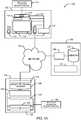
- FIGS. 1A and 1Billustrate example audio stream identification systems 100 and 150 for generating digital spectral signatures and identifying audio streams.
- the example audio stream identification systems 100 and 150may be implemented as a television broadcast information identification system and a radio broadcast information identification system, respectively.
- the example audio stream identification system 100includes a monitoring site 102 (e.g., a monitored household), a reference site 104, and a central information processing facility 106.
- Monitoring television broadcast informationinvolves generating monitored signatures at the monitoring site 102 based on the audio data of television broadcast information and communicating the monitored signatures to the central information processing facility 106 via a network 108.
- Reference signaturesmay be generated at the reference site 104 and may also be communicated to the central information processing facility 106 via the network 108.
- the audio content represented by a monitored signature that is generated at the monitoring site 102may be identified at the central information processing facility 106 by comparing the monitored signature to one or more reference signatures until a match is found.
- monitored signaturesmay be communicated from the monitoring site 102 to the reference site 104 and compared one or more reference signatures at the reference site 104.
- the reference signaturesmay be communicated to the monitoring site 102 and compared with the monitored signatures at the monitoring site 102.
- the monitoring site 102may be, for example, a household for which the media consumption of an audience is monitored.
- the monitoring site 102may include a plurality of media delivery devices 110, a plurality of media presentation devices 112, and a signature generator 114 that is used to generate monitored signatures associated with media presented at the monitoring site 102.
- the plurality of media delivery devices 110may include, for example, set top box tuners (e.g., cable tuners, satellite tuners, etc.), DVD players, CD players, radios, personal computers, etc. Some or all of the media delivery devices 110 such as, for example, set top box tuners may be communicatively coupled to one or more broadcast information reception devices 116, which may include a cable, a satellite dish, an antenna, and/or any other suitable device for receiving broadcast information.
- the media delivery devices 110may be configured to reproduce media information (e.g., audio information, video information, web pages, still images, etc.) based on, for example, broadcast information and/or stored information.
- Broadcast informationmay be obtained from the broadcast information reception devices 116 and stored information may be obtained from any information storage medium (e.g., a DVD, a CD, a tape, a hard drive, a flash memory card, etc.).
- the media delivery devices 110are communicatively coupled to the media presentation devices 112 and configurable to communicate media information to the media presentation devices 112 for presentation.
- the media presentation devices 112may include televisions having a display device and/or a set of speakers by which audience members consume, for example, broadcast television information, music, movies, etc.
- the signature generator 114may be used to generate monitored digital signatures based on audio information, as described in greater detail below.
- the signature generator 114may be configured to generate monitored signatures based on monitored audio streams that are reproduced by the media delivery devices 110 and/or presented by the media presentation devices 112.
- the signature generator 114may be communicatively coupled to the media delivery devices 110 and/or the media presentation devices 112 via an audio monitoring interface 118. In this manner, the signature generator 114 may obtain audio streams associated with media information that is reproduced by the media delivery devices 110 and/or presented by the media presentation devices 112. Additionally or alternatively, the signature generator 114 may be communicatively coupled to microphones (not shown) that are placed in proximity to the media presentation devices 112 to detect audio streams.
- the signature generator 114may also be communicatively coupled to the central information processing facility 106 via the network 108.
- the network 108may be used to communicate signatures (e.g., digital spectral signatures), control information, and/or configuration information between the monitoring site 102, the reference site 104, and the central information processing facility 106.
- signaturese.g., digital spectral signatures
- control informatione.g., configuration information
- configuration informatione.g., configuration information
- Any wired or wireless communication systemsuch as, for example, a broadband cable network, a DSL network, a cellular telephone network, a satellite network, and/or any other communication network may be used to implement the network 108.
- the reference site 104may include a plurality of broadcast information tuners 120, a reference signature generator 122, a transmitter 124, a database or memory 126, and broadcast information reception devices 128.
- the reference signature generator 122 and the transmitter 124may be communicatively coupled to the memory 126 to store reference signatures therein and/or to retrieve stored reference signatures therefrom.
- the broadcast information tuners 120may be communicatively coupled to the broadcast information reception devices 128, which may include a cable, an antenna, a satellite dish, and/or any other suitable device for receiving broadcast information. Each of the broadcast information tuners 120 may be configured to tune to a particular broadcast channel. In general, the number of tuners at the reference site 104 is equal to the number of channels available in a particular broadcast region. In this manner, reference signatures may be generated for all of the media information transmitted over all of the channels in a broadcast region. The audio portion of the tuned media information may be communicated from the broadcast information tuners 120 to the reference signature generator 122.
- the reference signature generator 122may be configured to obtain the audio portion of all of the media information that is available in a particular broadcast region. The reference signature generator 122 may then generate a plurality of reference signatures (as described in greater detail below) based on the audio information and store the reference signatures in the memory 126. Although one reference signature generator is shown in FIG. 1 , a plurality of reference signature generators may be used in the reference site 104. For example, each of the plurality of signature generators may be communicatively coupled to a respective one of the broadcast information tuners 120.
- the transmitter 124may be communicatively coupled to the memory 126 and configured to retrieve signatures therefrom and communicate the reference signatures to the central information processing facility 106 via the network 108.
- the central information processing facility 106may be configured to compare monitored signatures received from the monitoring site 102 to reference signatures received from the reference site 104. In addition, the central information processing facility 106 may be configured to identify monitored audio streams by matching monitored signatures to reference signatures and using the matching information to retrieve television program identification information (e.g., program title, broadcast time, broadcast channel, etc.) from a database.
- the central information processing facility 106includes a receiver 130, a signature analyzer 132, and a memory 134, all of which are communicatively coupled as shown.
- the receiver 130may be configured to receive monitored signatures and reference signatures via the network 108.
- the receiver 130is communicatively coupled to the memory 134 and configured to store the monitored signatures and the reference signatures therein.
- the signature analyzer 132may be used to compare reference signatures to monitored signatures.
- the comparisons carried out by the signature analyzer 132may include searching for monitored signatures within reference signatures and/or identifying some or all monitored signatures within the reference signatures. Additionally, in some examples, the signature analyzer 132 can match a reference signature against itself (i.e., can compare against itself) in order to find repeat content, such as, for example, all of the same commercial occurrences, all multicasts, replays, etc. Further, the signature analyzer 132 can match monitored signatures against monitored signatures taken for the same or other reasons.
- the signature analyzer 132is communicatively coupled to the memory 134 and configured to retrieve the monitored signatures and the reference signatures from the same.
- the signature analyzer 132may be configured to retrieve reference signatures and monitored signatures from the memory 134 and compare the monitored signatures to the reference signatures until a match is found.
- the memory 134may be implemented using any machine accessible information storage medium such as, for example, one or more hard drives, one or more optical storage devices, etc.
- the signature analyzer 132may instead be located at the reference site 104. In such a configuration, the monitored signatures may be communicated from the monitoring site 102 to the reference site 104 via the network 108. Alternatively, the memory 134 may be located at the monitoring site 102 and reference signatures may be added periodically to the memory 134 via the network 108 by transmitter 124. Additionally, although the signature analyzer 132 is shown as a separate device from the signature generators 114 and 122, the signature analyzer 132 may be integral with the reference signature generator 122 and/or the signature generator 114. Still further, although FIG. 1 depicts a single monitoring site (i.e., the monitoring site 102) and a single reference site (i.e., the reference site 104), multiple such sites may be coupled via the network 108 to the central information processing facility 106.
- the audio stream identification system 150 of FIG. 1Bmay be configured to monitor and identify audio streams associated with radio broadcast information.
- the audio stream identification system 150is used to monitor the content that is broadcast by a plurality of radio stations in a particular broadcast region.
- the audio stream identification system 150may be used to monitor music, songs, advertisements, etc. that are broadcast within a broadcast region and the number of times that they are broadcast. This type of media tracking may be used to determine royalty payments, proper use of copyrights, etc. associated with each audio composition.
- the audio stream identification system 150includes a monitoring site 152, a central information processing facility 154, and the network 108.
- the monitoring site 152is configured to receive all radio broadcast information that is available in a particular broadcast region and generate monitored signatures based on the radio broadcast information.
- the monitoring site 152includes the plurality of broadcast information tuners 120, the transmitter 124, the memory 126, and the broadcast information reception devices 128, all of which are described above in connection with FIG. 1A .
- the monitoring site 152includes a signature generator 156.
- the broadcast information reception devices 128are configured to receive radio broadcast information and the broadcast information tuners 120 are configured to tune to the radio broadcast stations.
- the number of broadcast information tuners 120 at the monitoring site 152may be equal to the number of radio broadcasting stations in a particular broadcast region.
- the signature generator 156is configured to receive the tuned to audio information from each of the broadcast information tuners 120 and generate monitored signatures for the same. Although one signature generator is shown (i.e., the signature generator 156), the monitoring site 152 may include multiple signature generators, each of which may be communicatively coupled to one of the broadcast information tuners 120.
- the signature generator 156may store the monitored signatures in the memory 126.
- the transmitter 124may retrieve the monitored signatures from the memory 126 and communicate them to the central data collection facility 154 via the network 108.
- the central information processing facility 154is configured to receive monitored signatures from the monitoring site 152, generate reference signatures based on reference audio streams, and compare the monitored signatures to the reference signatures.
- the central information processing facility 154includes the receiver 130, the signature analyzer 132, and the memory 134, all of which are described in greater detail above in connection with FIG. 1A .
- the central information processing facility 154includes a reference signature generator 158.
- the reference signature generator 158is configured to generate reference signatures based on reference audio streams.
- the reference audio streamsmay be stored on any type of machine accessible medium such as, for example, a CD, a DVD, a digital audio tape (DAT), etc.
- artists and/or record producing companies or other media content ownerssend their audio works (i.e., music, songs, etc.) to the central information processing facility 154 to be added to a reference library.
- the reference signature generator 158may read the audio data from the machine accessible medium and generate a plurality of reference signatures based on each audio work (e.g., the captured audio 300 of FIG. 3 ).
- the reference signature generator 158may then store the reference signatures in the memory 134 for subsequent retrieval by the signature analyzer 132.
- Identification information(e.g., song title, artist name, track number, etc.) associated with each reference audio stream may be stored in a database and may be indexed based on the reference signatures.
- the central information processing facility 154includes a database of reference signatures and identification information corresponding to all known and available song titles.
- the receiver 130is configured to receive monitored signatures from the network 108 and store the monitored signatures in the memory 134.
- the monitored signatures and the reference signaturesare retrieved from the memory 134 by the signature analyzer 132 for use in identifying the monitored audio streams broadcast within a broadcast region.
- the signature analyzer 132may be used to compare reference signatures to monitored signatures. The comparisons carried out by the signature analyzer 132 may include searching for monitored signatures within reference signatures and/or identifying some or all monitored signatures within the reference signatures.
- the signature analyzer 132can match a reference signature against itself (i.e., can compare against itself) in order to find repeat content, such as, for example, all of the same commercial occurrences, all multicasts, replays, etc. Further, the signature analyzer 132 can match monitored signatures against monitored signatures taken for the same or other reasons. Thus, the signature analyzer 132 may identify the monitored audio streams by first matching a monitored signature to a reference signature. The match information and/or the matching reference signature are then used to retrieve identification information (e.g., a song title, a song track, an artist, etc.) from a database stored in the memory 134.
- identification informatione.g., a song title, a song track, an artist, etc.
- each monitoring sitemay be communicatively coupled to the network 108 and configured to generate monitored signatures.
- each monitoring sitemay be located in a respective broadcast region and configured to monitor the content of the broadcast stations within a respective broadcast region.
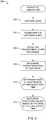
- FIG. 2is a flow diagram representing an example signature generation process 200.
- the signature generation process 200first captures audio that is to be characterized by a signature (block 202).
- An example time domain plot of captured audiois shown in FIG. 3 at reference numeral 300.
- the audiomay be captured from an audio source, such as, for example a hardwired connection to an audio source or a microphone/wireless connection to an audio source. If the audio source is analog, the capturing includes digitizing/sampling the analog audio source using, for example, an analog-to-digital converter.
- the audio sourcemay be sampled at a rate of 8 kilohertz (kHz), which is referred to as a sampling rate (Fs).
- kHz8 kilohertz
- Fssampling rate
- analog audiois represented by digital samples thereof that are taken at the rate of eight thousand samples per second, or every 125 microseconds ( ⁇ s). Each of the audio samples may be represented by 16 bits of resolution. If audio source contains more then one channel, e.g. stereo format having 2 channels of sound, or Dolby Digital ⁇ format having up to 6 channels, then multiple channels can be downconverted to a single channel prior to generating the signatures. Downconverting can be done by one of many well-known techniques. In some example, one can generate multiple signatures from more then one channel of sound concurrently.
- the process 200transforms the captured audio (block 204).
- the transformationmay be a transformation from the time domain into the frequency domain using a Discrete Fourier Transform (DFT).
- DFTDiscrete Fourier Transform
- the M real-valued samples of captured audiomay be converted into an audio spectrum that is represented by M/2 complex-valued DFT coefficients.
- the transformed audiois divided into, for example, 48 non-overlapping frequency bands (block 206).
- an audio spectrum 400 corresponding to the time domain audio signal 300 of FIG. 3is shown as divided into a number of bands, three of which are referred to at reference numerals 402, 404, and 406.
- the selected bandswhich are shown as shaded in FIG. 4 , that lie between reference numerals 402 and 406 may cover only a portion of the audio spectrum and may be selected in any appropriate manner.
- the 48 bandsmay be defined in Table 1, below.
- the process 200determines characteristics for each spectral band (block 208).
- the characteristicsmay be any range of characteristics, such as amplitude, energy, or the like.
- the characteristicis energy within each of the bands, which results in 48 real values: E 1 t , E 2 t , E 3 t , ..., E 48 t , representing the energy in each of the 48 bands at time t.
- the process 200determines band characteristic differences over time (block 210).
- the determination of band characteristic differences over timemay include various comparisons of band energies with bands at different times or may include comparisons of band energies across bands at different times. Further detail regarding one example technique for determining band characteristic differences over time is provided below in conjunction with FIG. 5 .
- the process 200determines signature values (block 212).
- signature valuesOne example process for determining signature values from band characteristic differences is described below in conjunction with FIG. 6 .
- various tests or comparisonscan be performed on the characteristic differences and from those comparisons, bits may be selected to represent/characterize the captured audio.
- comparisons on the 48 different bandswill ultimately end up resulting in 48 different signature bits representative of the captured audio.
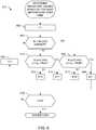
- FIG. 5shows one example process 210 to determine band characteristic differences over time.
- the point at which the process 210 operates in when the band energiese.g., the 48 different band energies
- a counteris initialized to a starting condition, such as for example reset to a count of 1 (block 502).
- the process 210determines if the current count (i.e., the value of i) is an odd number (block 504).
- E t irepresents the energy in band i at time t
- E T i+1represents the energy in band i+1 at time T.
- the value of ⁇ tcan be arbitrary and chosen differently for different bands.
- the processdetermines if the last band has been reached in the spectrum (block 510). For example, if there are 48 bands in the spectrum, the process 210 will determine if the counter i has reached the value of 48.
- the process 210ends and control returns to block 212 of FIG. 2 .
- the process 210increments the counter to select the next band (block 512) and the processing represented by blocks 504, 506, 508, and 510 is repeated.
- the signature valuesare determined.
- the signature valuesmay be determined according to a process 212, shown in FIG. 6 .
- the process 212is initialized at block 602 of FIG. 6 .
- the initializationmay include any number of different items, but includes setting an index (i) to one. If i is an odd number (block 604), a test (block 606) including two evaluations is undertaken to determine whether the i th bit should be set to a logical one or a logical zero. In particular, the test includes determining if the characteristic difference for the i th band is positive (i.e., d i >0) and determining if the characteristic difference for the i th band is larger than the negative of the characteristic difference for the (i+1) th band (i.e., d i >-d i+1 ). If each of the evaluations is true, an i th signature bit is set to a logical one (block 608). Alternatively, if either of the evaluations is not true, the i th signature bit is set to a logical zero (block 610).
- the process 212performs a second test including two evaluations (block 612).
- the testincludes determining if the characteristic difference for the i th band is positive (d i >0) and determining if the characteristic difference for the i th band is larger than the negative of the characteristic difference for the (i-1) th band (d i >-d i-1 ). If each of the evaluations is true, an i th signature bit is set to a logical one (block 614). Alternatively, if either of the evaluations is not true, the i th signature bit is set to a logical zero (block 616).
- the process 212determines if the last bit value has been calculated (block 618). For example, if there are 48 bits in a signature, the process 212 determines if the index i has been incremented to a value of 48 (block 618). If the last signature bit has been determined, the process 212 ends and returns control to its calling process. Alternatively, if the last signature bit has not been determined (block 618), the process 212 increments the index i (block 620) and the process 212 continues to execute from the block 604.
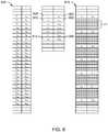
- FIG. 7shows one example signature matching process 700 that may be carried out to compare reference signatures (i.e., signatures determined at a reference site(s)) to monitored signatures (i.e., signatures determined at a monitoring site).
- the ultimate goal of signature matchingis to find the closest match between a query audio signature (e.g., monitored audio) and signatures in a database (e.g., signatures taken based on reference audio).
- the comparisonmay be carried out at a reference site, a monitoring site, or any other data processing site having access to the monitored signatures and a database containing reference signatures.
- a signature collectionmay include a number of monitored signatures, three of which are shown in FIG. 8 at reference numerals 802, 804 and 806. Each of the signatures is represented by a sigma ( ⁇ ). Each of the monitored signatures 802, 804, 806 may include timing information 808, 810, 812, whether that timing information is implicit or explicit.
- a queryis then made to a database containing reference signatures (block 704) to identify the signature in the database having the closest match.
- the measure of similarity (closeness) between signaturesis taken to be a Hamming distance, namely, the number of position at which the values of query and reference bit strings differ.
- a database of signatures and timing informationis shown at reference numeral 816.
- the database 806may include any number of different signatures from different media presentations.
- An associationis then made between the audio and/or video program (i.e., media content) associated with the matching reference signature and the unknown signature (block 706).
- the process 700may then establish an offset between the monitored signature and the reference signature (block 708).
- This offsetallows for tremendous improvement in distinguishing between the true positive matches and the false positive matches. False positive matches will occur with essentially random values of offsets, while the true positive matches will have a nearly constant offset value, due to local continuity of media consumption, i.e. viewing, monitoring, etc.
- this offsetis helpful because, as noted above, the monitored signatures may be less frequent than the reference signatures.
- the monitored signaturesmay be expanded 818 to match the timing of the reference signature database 816. In making this expansion is becomes clear that the monitored signature matches the reference signature every fourth time period.
- this matchingmay be only approximate because the perfect alignment between the blocks of audio samples used to compute the signatures is difficult to achieve.
- the spacing between signatures in the monitored signatures stream 818is referred to as "unobserved".
- the use of the offset valuesis typically accomplished in the post-processing and filtering of match results obtained in 706.
- the example methods, processes, and/or techniques described abovemay be implemented by hardware, software, and/or any combination thereof. More specifically, the example methods may be executed in hardware defined by the block diagrams of FIGS. 9 and 10 . The example methods, processes, and/or techniques may also be implemented by software executed on a processor system such as, for example, the processor system 1110 of FIG. 11 .
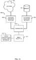
- FIG. 9is a block diagram of an example signature generation system 900 for generating digital spectral signatures.
- the example signature generation system 900may be used to generate monitored signatures and/or reference signatures based on spectral energies and comparisons between spectral energies both in the present time and at other times in the past or in the future.
- the example signature generation system 900may be used to implement the signature generators 114 and 122 of FIG. 1A or the signature generators 156 and 158 of FIG. 1B .
- the example signature generation system 900may be used to implement the example methods of FIGS. 5 and 6 .
- the example signature generation system 900includes a sample generator 902, a timing device 903, a reference time generator 904, a transformer 906, a divider 908, a characteristic determiner 910, a subtractor 912, a signature generator 914, storage, and a data communication interface 918, all of which may be communicatively coupled as shown.
- the example signature generation system 900may be configured to obtain an example audio stream, acquire a plurality of audio samples from the example audio stream, and generate digital spectral signatures based on the audio samples.
- the sample generator 902may be configured to obtain the example audio stream, such as a stream resulting in the captured audio 300 of FIG. 3 .
- the stream 300may be any analog or digital audio stream. If the example audio stream 920 is an analog audio stream, the sample generator 902 may be implemented using an analog-to-digital converter. Additionally, the sample generator 902 may be configured to acquire and/or extract audio samples at any desired sampling frequency F s . For example, as described above, the sample generator may be configured to acquire M samples at 8 kHz and may use 16 bits to represent each sample. In such an arrangement, M may be any number of samples such as, for example, 8192.
- the sample generator 902may also notify the reference time generator 904 when an audio sample acquisition process begins. The sample generator 902 communicates samples to the transformer 906.
- the timing device 903may be configured to generate time data and/or timestamp information and may be implemented by a clock, a timer, a counter, and/or any other suitable device.
- the timing device 903may be communicatively coupled to the reference time generator 904 and may be configured to communicate time data and/or timestamps to the reference time generator 904.
- the timing device 903may also be communicatively coupled to the sample generator 902 and may assert a start signal or interrupt to instruct the sample generator 902 to begin collecting or acquiring audio sample data.
- the timing device 903may be implemented by a real-time clock having a 24-hour period that tracks time at a resolution of milliseconds.
- the timing device 903may be configured to reset to zero at midnight and track time in milliseconds with respect to midnight.
- the timing device 903may send timestamps directly to the signature determiner 914 so the time timestamps may be attached to signatures generated by the signature determiner 914, before storage of the signatures.
- the reference time generator 904may initialize a reference time t 0 when a notification is received from the sample generator 902.
- the reference time t 0may be used to indicate the time within an audio stream at which a signature is generated.
- the reference time generator 904may be configured to read time data and/or a timestamp value from the timing device 903 when notified of the beginning of a sample acquisition process by the sample generator 902. The reference time generator 904 may then store the timestamp value as the reference time t 0 .
- the transformer 906may be configured to perform an M point DFT, wherein M is the number of samples obtained by the sample generator 902. For example, if the sample generator obtains 8192 real samples, the transformer will produce a spectrum from the samples wherein the spectrum is represented by 4096 complex Fourier coefficients.
- the divider 908may be configured to identify several frequency bands (e.g., 48 bands) within the DFT generated by the transformer 906.
- the selected bandsmay, but preferably do not overlap with one another.
- the bandsmay be selected according to any technique. In one example, the 48 bands are defined as explained above in conjunction with FIG. 2 .
- the characteristic determiner 910may be configured to obtain characteristics representing the frequency spectrum in each of the 48 bands. For example, the characteristic determiner 910 may calculate the energy in each of the 48 bands. Alternatively, other characteristics such as amplitude, phase, etc. may be selected as characteristics of each of the bands.
- the signature determiner 914operates on the resulting values from the subtractor 912 to produce one signature bit for each of the 48 frequency bands. This operation may be very similar or identical to the process 212 described above in conjunction with FIG. 6 . That is, the signature bit values may be based on whether an index is odd or even and whether certain comparisons of the difference values from the subtractor 912 are true.
- One example detail of the signature generation processis provided above in conjunction with FIG. 6 .
- the signature bitsare output to the storage 916.
- the storagemay be any suitable medium for accommodating signature storage.
- the storage 916may be a memory such as random access memory (RAM), flash memory, or the like. Additionally or alternatively, the storage 916 may be a mass memory such as a hard drive, an optical storage medium, a tape drive, or the like.
- the storage 916is coupled to the data communication interface 918.
- the signature information in the storage 916may be communicated to a collection facility, a reference site, or the like, using the data communication interface 918.
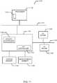
- FIG. 10is a block diagram of an example signature comparison system 1000 for comparing digital spectral signatures.
- the example signature comparison system 1000may be used to compare monitored signatures with reference signatures.
- the example signature comparison system 1000may be used to implement the signature analyzer 132 of FIG. 1A to compare monitored signatures with reference signatures.
- the example signature comparison system 1000may be used to implement the example process of FIG. 7 .
- the example signature comparison system 1000includes a monitored signature receiver 1002, a reference signature receiver 1004, a comparator 1006, a media identifier 1010, and a media identification look-up table interface 1012, all of which may be communicatively coupled as shown.
- the monitored signature receiver 1002may be configured to obtain monitored signatures via the network 108 ( FIG. 1 ) and communicate the monitored signatures to the comparator 1006.
- the reference signature receiver 1004may be configured to obtain reference signatures from the memory 134 ( FIGS. 1A and 1B ) and communicate the reference signatures to the comparator 1006.
- the comparator 1006may be configured to compare reference signatures to monitored signatures using any number of different techniques including, for example, hash matching, and the like.
- the comparator 1006filters out non-matching reference signatures.
- the media identifier 1010may obtain the matching reference signature and in cooperation with the media identification look-up table interface 1012 may identify the media information associated with an unidentified audio stream (e.g., the example monitored audio stream 300 of FIG. 3 ).
- the media identification look-up table interface 1012may be communicatively coupled to a media identification look-up table or a database that is used to cross-reference media identification information (e.g., movie title, show title, song title, artist name, episode number, etc.) based on reference signatures. In this manner, the media identifier 1010 may retrieve media identification information from the media identification database based on the matching reference signatures.
- FIG. 11is a block diagram of an example processor system 1110 that may be used to implement the apparatus and methods described herein.
- the processor system 1110includes a processor 1112 that is coupled to an interconnection bus or network 1114.
- the processor 1112includes a register set or register space 116, which is depicted in FIG. 11 as being entirely on-chip, but which could alternatively be located entirely or partially off-chip and directly coupled to the processor 1112 via dedicated electrical connections and/or via the interconnection network or bus 1114.
- the processor 1112may be any suitable processor, processing unit or microprocessor.
- the system 1110may be a multi-processor system and, thus, may include one or more additional processors that are identical or similar to the processor 1112 and that are communicatively coupled to the interconnection bus or network 1114.
- the processor 1112 of FIG. 11is coupled to a chipset 1118, which includes a memory controller 1120 and an input/output (I/O) controller 1122.
- a chipsettypically provides I/O and memory management functions as well as a plurality of general purpose and/or special purpose registers, timers, etc. that are accessible or used by one or more processors coupled to the chipset.
- the memory controller 1120performs functions that enable the processor 1112 (or processors if there are multiple processors) to access a system memory 1124 and a mass storage memory 1125.
- the system memory 1124may include any desired type of volatile and/or nonvolatile memory such as, for example, static random access memory (SRAM), dynamic random access memory (DRAM), flash memory, read-only memory (ROM), etc.
- the mass storage memory 1125may include any desired type of mass storage device including hard disk drives, optical drives, tape storage devices, etc.
- the I/O controller 1122performs functions that enable the processor 1112 to communicate with peripheral input/output (I/O) devices 1126 and 1128 via an I/O bus 1130.
- the I/O devices 1126 and 1128may be any desired type of I/O device such as, for example, a keyboard, a video display or monitor, a mouse, etc. While the memory controller 1120 and the I/O controller 1122 are depicted in FIG. 11 as separate functional blocks within the chipset 1118, the functions performed by these blocks may be integrated within a single semiconductor circuit or may be implemented using two or more separate integrated circuits.
- the methods described hereinmay be implemented using instructions stored on a computer readable medium that are executed by the processor 1112.
- the computer readable mediummay include any desired combination of solid state, magnetic and/or optical media implemented using any desired combination of mass storage devices (e.g., disk drive), removable storage devices (e.g., floppy disks, memory cards or sticks, etc.) and/or integrated memory devices (e.g., random access memory, flash memory, etc.).
Landscapes
- Engineering & Computer Science (AREA)
- Signal Processing (AREA)
- Multimedia (AREA)
- Physics & Mathematics (AREA)
- Theoretical Computer Science (AREA)
- Library & Information Science (AREA)
- Acoustics & Sound (AREA)
- Data Mining & Analysis (AREA)
- General Physics & Mathematics (AREA)
- General Engineering & Computer Science (AREA)
- Databases & Information Systems (AREA)
- Testing, Inspecting, Measuring Of Stereoscopic Televisions And Televisions (AREA)
- Signal Processing For Digital Recording And Reproducing (AREA)
- Compression, Expansion, Code Conversion, And Decoders (AREA)
Description
- The present disclosure relates generally to media monitoring and, more particularly, to methods and apparatus for generating signatures for use in identifying media information.
- Identifying media information and more specifically audio streams (e.g., audio information) using signature matching techniques is well known. Known signature matching techniques are often used in television and radio audience metering applications and are implemented using several methods for generating and matching signatures. For example, in television audience metering applications, signatures are generated at monitoring sites (e.g., monitored households) and reference sites. Monitoring sites typically include locations such as, for example, households where the media consumption of audience members is monitored. For example, at a monitoring site, monitored signatures may be generated based on audio streams associated with a selected channel, radio station, etc. The monitored signatures may then be sent to a central data collection facility for analysis. At a reference site, signatures, typically referred to as reference signatures, are generated based on known programs that are provided within a broadcast region. The reference signatures may be stored at the reference site and/or a central data collection facility and compared with monitored signatures generated at monitoring sites. A monitored signature may be found to match with a reference signature and the known program corresponding to the matching reference signature may be identified as the program that was presented at the monitoring site.
US Patent 5,572,246 discloses producing signatures for characterizing an interval of a video signal representing a picture for use in broadcast segment recognition. The signature is produced based on portions of the video signal representing corresponding regions of the picture each spaced by a certain amount from a nominal edge of the picture. A shift in the video signal corresponding with a shift in the edge of the picture from a nominal edge of the picture is detected. The portions of the video signal are adjusted to compensate for the shift in the edge of the picture and a signature is produced based on the adjusted portions of the video signal.- According to a first aspect, it is presented a method of characterizing media comprising: capturing a block of audio; converting at least a portion of the block of audio into a frequency domain representation; dividing the frequency domain representation into a plurality of bands; determining a characteristic difference of a first band of the plurality of bands based on a comparison of a characteristic of the first band and a characteristic of a second band different from the first band, wherein the characteristic of the first band occurs at a time that is different than a time at which the characteristic of the second band takes place; and determining a signature bit based on the characteristic difference. Capturing the block of audio may comprise obtaining audio via a hardwired connection. Capturing the block of audio may comprise obtaining audio via a wireless connection. Converting at least a portion of the block of audio into the frequency domain representation may comprise the use of a Fourier transformation. Dividing the frequency domain representation into the plurality of bands may comprise grouping frequency components that are adjacent in the frequency domain representation. The frequency components may have frequencies in an audible frequency range. Determining the characteristic of a selected band may comprise determining an energy in the selected band. The first band may have a first frequency that is higher than a second frequency of the second band. The comparison may comprise a subtraction. The first band may have a first frequency that is higher than a second frequency of the second band, and the characteristic of the first band may have occurred later in time than the characteristic of the second band. The first band may have a highest frequency that is lower than a lowest frequency of the second band. The characteristic of the first band may have occurred later in time than the characteristic of the second band. Determining the signature bit based on the characteristic difference may comprise comparing the characteristic difference to a value of zero. Determining the signature bit based on the characteristic difference may further comprise comparing the characteristic difference to another characteristic difference.
- According to a further aspect, it is presented a signature generation system comprising: a sample generator to capture a block of audio; a transformer to convert at least a portion of the block of audio into a frequency domain representation; a divider to divide the frequency domain representation into a plurality of bands; a characteristic determiner to determine a first characteristic of a first band of the plurality of bands and a second characteristic of a second band different from the first band, wherein the first characteristic of the first band occurs at a time that is different than a time at which the second characteristic of the second band takes place; a subtractor to determine a characteristic difference between the first characteristic and the second characteristic; and a signature determiner to determine a signature bit based on the characteristic difference. Capturing the block of audio may comprise obtaining audio via a hardwired connection or obtaining audio via a wireless connection. Converting at least a portion of the block of audio into the frequency domain representation may comprise the use of a Fourier transformation. Dividing the frequency domain representation into the plurality of bands may comprise grouping frequency components that are adjacent in the frequency domain representation. The frequency components may have frequencies in an audible frequency range. Determining the characteristic of a selected band may comprise determining an energy in the selected band. The first band may have a lowest frequency that is higher than a highest frequency of the second band. The characteristic of the first band may have occurred later in time than the characteristic of the second band.
- According to a third aspect, it is presented a machine readable medium storing instructions that, when executed, cause a machine to: capture a block of audio; convert at least a portion of the block of audio into a frequency domain representation; divide the frequency domain representation into a plurality of bands; determine a characteristic difference of a first band of the plurality of bands based on a comparison of a characteristic of the first band and a characteristic of a second band different from the first band, wherein the characteristic of the first band occurs at a time that is different than a time at which the characteristic of the second band takes place; and determine a signature bit based on the characteristic difference. Capturing the block of audio may comprise obtaining audio via a hardwired connection or obtaining audio via a wireless connection. Converting at least a portion of the block of audio into the frequency domain representation may comprise the use of a Fourier transformation. Dividing the frequency domain representation into the plurality of bands may comprise grouping frequency components that are adjacent in the frequency domain representation. The frequency components may have frequencies in an audible frequency range. Determining the characteristic of a selected band may comprise determining an energy in the selected band. The first band may have a first frequency that is higher than a second frequency of the second band. The comparison may comprise a subtraction. The first band may have a first frequency that is higher than a second frequency of the second band, and the characteristic of the first band may have occurred later in time than the characteristic of the second band.
- The comparison may comprise a subtraction. The first band may have a first frequency that is lower than a second frequency of the second band. The first band may have a first frequency that is lower than a second frequency of the second band, and the characteristic of the first band may have occurred later in time than the characteristic of the second band. Determining the signature bit based on the characteristic difference may comprise comparing the characteristic difference to a value of zero. Determining the signature bit based on the characteristic difference may further comprise comparing the characteristic difference to another characteristic difference.
FIGS. 1A and1B illustrate example audio stream identification systems for generating digital spectral signatures and identifying audio streams.FIG. 2 is a flow diagram illustrating an example signature generation process.FIG. 3 is a time-domain representation of an example monitored audio stream.FIG. 4 is a frequency domain representation of an example monitored audio stream, wherein the spectrum of the example monitored audio stream is divided into frequency bands.FIG. 5 is a flow diagram of one example way to implement the determine band characteristic differences over time process shown generally inFIG. 2 .FIG. 6 is a flow diagram of one example way to implement the determine signature values based on the band differences over time process shown generally inFIG. 2 .FIG. 7 is a flow diagram of an example signature matching process.FIG. 8 is a diagram showing how signatures may be compared in accordance with the flow diagram ofFIG. 7 .FIG. 9 is a block diagram of an example signature generation system for generating digital spectral signatures based on audio streams.FIG. 10 is a block diagram of an example signature comparison system for comparing digital spectral signatures.FIG. 11 is a block diagram of an example processor system that may be used to implement the methods and apparatus described herein.- Although the following discloses example systems including, among other components, software executed on hardware, it should be noted that such systems are merely illustrative and should not be considered as limiting. For example, it is contemplated that any or all of these hardware and software components could be embodied exclusively in hardware, exclusively in software, or in any combination of hardware and software. Accordingly, while the following describes example systems, persons of ordinary skill in the art will readily appreciate that the examples provided are not the only way to implement such systems.
- The methods and apparatus described herein generally relate to generating digital spectral signatures, which may be used to identify media information. A spectral signature is an audio descriptor that can accurately characterize audio signals for the purpose of matching, indexing, or database retrieval. In particular, the disclosed methods and apparatus are described with respect to generating digital spectral signatures based on audio streams (e.g., audio information). However, the methods and apparatus described herein may also be used to generate digital spectral signatures based on any other type of media information such as, for example, video information, web pages, still images, computer data, etc. Further, the media information may be associated with broadcast information (e.g., television information, radio information, etc.), information reproduced from any storage medium (e.g., compact discs (CD), digital versatile discs (DVD), etc.), or any other information that is associated with an audio stream, a video stream, or any other media information for which the digital spectral signatures are generated. In one particular example, the audio streams are identified based on digital spectral signatures that include monitored digital signatures generated at a monitoring site (e.g., a monitored household) and reference digital signatures generated and/or stored at a reference site and/or a central data collection facility.
- As described in detail below, the methods and apparatus described herein identify media information including audio streams based on digital spectral signatures. The digital spectral signatures may be formed using energies from different bands of the spectrum of the audio stream being processed. These energies may be compared both between different frequency bands and across time to develop values that are used to create signature bits representing the audio stream during a particular period of time.
- Frequency components of an audio signal are typically obtained by transforming the audio signal data (e.g., an audio stream) from the time domain to the frequency domain using, for example, a discrete Fourier transformation (DFT) or any other suitable transform, be it based on a Fourier Transform or not. The Fourier Transform can be used to analyze the frequency components in an audio signal and identify the spectral power of each frequency component. The spectral powers may then be used to generate digital spectral signatures.
- Digital spectral signatures may also be generated based on wavelet transforms which transform audio data from the time domain to the wavelet domain. In general, wavelet transforms may be used to decompose blocks or frames of data (e.g., time domain audio samples) into multiple sub-bands, thereby allowing data sets to be analyzed at various scales and/or resolutions. By separating data into multiple sub-bands, a wavelet transform may be used to analyze each time interval of data at a desired scale or resolution.
- Monitored signatures may be generated at a monitoring site based on audio streams associated with media information (e.g., a monitored audio stream) that is consumed by an audience. For example, a monitored signature may be generated based on the audio track of a television program presented at a monitoring site. The monitored signature may then be communicated to a central data collection facility for comparison to one or more reference signatures.
- Reference signatures are generated at a reference site and/or a central data collection facility based on audio streams associated with known media information. The known media information may include media that is broadcast within a region, media that is reproduced within a household, media that is received via the internet, etc. Each reference signature is stored in a memory with media identification information such as, for example, a song title, a movie title, broadcast time, unique content source identification, etc. When a monitored signature is received at the central data collection facility, the monitored signature is compared with one or more reference signatures until a match is found. This match information may then be used to identify the media information (e.g., monitored audio stream) from which the monitored signature was generated. For example, a look-up table or a database may be referenced to retrieve a media title, a program identity, an episode number, airing time, etc. that corresponds to the media information from which the monitored signature was generated.
- In one example, the rates at which monitored signatures and reference signatures are generated may be different. For example, for processing and other concerns, a monitored signature may be 25% of the data rate of a reference signature. For example, a 48-bit reference signature may be generated every 0.032 seconds, which results in a reference data rate of 48 bits/ 0.032 seconds or 187.5 bytes/second. In such an arrangement, a 48-bit monitored signature may be generated every 0.128 seconds, which results in a monitored data rate of 48 bits / 0.128 seconds or 46.875 bytes/second. Of course, in an arrangement in which the data rates of the monitored and reference signatures differ, this difference must be accounted for when comparing monitored signatures with reference signatures. For example, if the monitoring rate is 25% of the reference rate, each consecutive monitored signature will correspond to every fourth reference signature.
FIGS. 1A and1B illustrate example audiostream identification systems stream identification systems stream identification system 100 includes a monitoring site 102 (e.g., a monitored household), areference site 104, and a centralinformation processing facility 106.- Monitoring television broadcast information involves generating monitored signatures at the
monitoring site 102 based on the audio data of television broadcast information and communicating the monitored signatures to the centralinformation processing facility 106 via anetwork 108. Reference signatures may be generated at thereference site 104 and may also be communicated to the centralinformation processing facility 106 via thenetwork 108. The audio content represented by a monitored signature that is generated at themonitoring site 102 may be identified at the centralinformation processing facility 106 by comparing the monitored signature to one or more reference signatures until a match is found. Alternatively, monitored signatures may be communicated from themonitoring site 102 to thereference site 104 and compared one or more reference signatures at thereference site 104. In another example, the reference signatures may be communicated to themonitoring site 102 and compared with the monitored signatures at themonitoring site 102. - The
monitoring site 102 may be, for example, a household for which the media consumption of an audience is monitored. In general, themonitoring site 102 may include a plurality ofmedia delivery devices 110, a plurality ofmedia presentation devices 112, and asignature generator 114 that is used to generate monitored signatures associated with media presented at themonitoring site 102. - The plurality of
media delivery devices 110 may include, for example, set top box tuners (e.g., cable tuners, satellite tuners, etc.), DVD players, CD players, radios, personal computers, etc. Some or all of themedia delivery devices 110 such as, for example, set top box tuners may be communicatively coupled to one or more broadcastinformation reception devices 116, which may include a cable, a satellite dish, an antenna, and/or any other suitable device for receiving broadcast information. Themedia delivery devices 110 may be configured to reproduce media information (e.g., audio information, video information, web pages, still images, etc.) based on, for example, broadcast information and/or stored information. Broadcast information may be obtained from the broadcastinformation reception devices 116 and stored information may be obtained from any information storage medium (e.g., a DVD, a CD, a tape, a hard drive, a flash memory card, etc.). Themedia delivery devices 110 are communicatively coupled to themedia presentation devices 112 and configurable to communicate media information to themedia presentation devices 112 for presentation. Themedia presentation devices 112 may include televisions having a display device and/or a set of speakers by which audience members consume, for example, broadcast television information, music, movies, etc. - The
signature generator 114 may be used to generate monitored digital signatures based on audio information, as described in greater detail below. In particular, at themonitoring site 102, thesignature generator 114 may be configured to generate monitored signatures based on monitored audio streams that are reproduced by themedia delivery devices 110 and/or presented by themedia presentation devices 112. Thesignature generator 114 may be communicatively coupled to themedia delivery devices 110 and/or themedia presentation devices 112 via anaudio monitoring interface 118. In this manner, thesignature generator 114 may obtain audio streams associated with media information that is reproduced by themedia delivery devices 110 and/or presented by themedia presentation devices 112. Additionally or alternatively, thesignature generator 114 may be communicatively coupled to microphones (not shown) that are placed in proximity to themedia presentation devices 112 to detect audio streams. Thesignature generator 114 may also be communicatively coupled to the centralinformation processing facility 106 via thenetwork 108. - The
network 108 may be used to communicate signatures (e.g., digital spectral signatures), control information, and/or configuration information between themonitoring site 102, thereference site 104, and the centralinformation processing facility 106. Any wired or wireless communication system such as, for example, a broadband cable network, a DSL network, a cellular telephone network, a satellite network, and/or any other communication network may be used to implement thenetwork 108. - As shown in
FIG. 1A , thereference site 104 may include a plurality ofbroadcast information tuners 120, areference signature generator 122, atransmitter 124, a database ormemory 126, and broadcastinformation reception devices 128. Thereference signature generator 122 and thetransmitter 124 may be communicatively coupled to thememory 126 to store reference signatures therein and/or to retrieve stored reference signatures therefrom. - The
broadcast information tuners 120 may be communicatively coupled to the broadcastinformation reception devices 128, which may include a cable, an antenna, a satellite dish, and/or any other suitable device for receiving broadcast information. Each of thebroadcast information tuners 120 may be configured to tune to a particular broadcast channel. In general, the number of tuners at thereference site 104 is equal to the number of channels available in a particular broadcast region. In this manner, reference signatures may be generated for all of the media information transmitted over all of the channels in a broadcast region. The audio portion of the tuned media information may be communicated from thebroadcast information tuners 120 to thereference signature generator 122. - The
reference signature generator 122 may be configured to obtain the audio portion of all of the media information that is available in a particular broadcast region. Thereference signature generator 122 may then generate a plurality of reference signatures (as described in greater detail below) based on the audio information and store the reference signatures in thememory 126. Although one reference signature generator is shown inFIG. 1 , a plurality of reference signature generators may be used in thereference site 104. For example, each of the plurality of signature generators may be communicatively coupled to a respective one of the broadcast information tuners 120. - The
transmitter 124 may be communicatively coupled to thememory 126 and configured to retrieve signatures therefrom and communicate the reference signatures to the centralinformation processing facility 106 via thenetwork 108. - The central
information processing facility 106 may be configured to compare monitored signatures received from themonitoring site 102 to reference signatures received from thereference site 104. In addition, the centralinformation processing facility 106 may be configured to identify monitored audio streams by matching monitored signatures to reference signatures and using the matching information to retrieve television program identification information (e.g., program title, broadcast time, broadcast channel, etc.) from a database. The centralinformation processing facility 106 includes areceiver 130, asignature analyzer 132, and amemory 134, all of which are communicatively coupled as shown. - The
receiver 130 may be configured to receive monitored signatures and reference signatures via thenetwork 108. Thereceiver 130 is communicatively coupled to thememory 134 and configured to store the monitored signatures and the reference signatures therein. - The
signature analyzer 132 may be used to compare reference signatures to monitored signatures. The comparisons carried out by thesignature analyzer 132 may include searching for monitored signatures within reference signatures and/or identifying some or all monitored signatures within the reference signatures. Additionally, in some examples, thesignature analyzer 132 can match a reference signature against itself (i.e., can compare against itself) in order to find repeat content, such as, for example, all of the same commercial occurrences, all multicasts, replays, etc. Further, thesignature analyzer 132 can match monitored signatures against monitored signatures taken for the same or other reasons. - The
signature analyzer 132 is communicatively coupled to thememory 134 and configured to retrieve the monitored signatures and the reference signatures from the same. Thesignature analyzer 132 may be configured to retrieve reference signatures and monitored signatures from thememory 134 and compare the monitored signatures to the reference signatures until a match is found. Thememory 134 may be implemented using any machine accessible information storage medium such as, for example, one or more hard drives, one or more optical storage devices, etc. - Although the
signature analyzer 132 is located at the centralinformation processing facility 106 inFIG. 1A , thesignature analyzer 132 may instead be located at thereference site 104. In such a configuration, the monitored signatures may be communicated from themonitoring site 102 to thereference site 104 via thenetwork 108. Alternatively, thememory 134 may be located at themonitoring site 102 and reference signatures may be added periodically to thememory 134 via thenetwork 108 bytransmitter 124. Additionally, although thesignature analyzer 132 is shown as a separate device from thesignature generators signature analyzer 132 may be integral with thereference signature generator 122 and/or thesignature generator 114. Still further, althoughFIG. 1 depicts a single monitoring site (i.e., the monitoring site 102) and a single reference site (i.e., the reference site 104), multiple such sites may be coupled via thenetwork 108 to the centralinformation processing facility 106. - The audio
stream identification system 150 ofFIG. 1B may be configured to monitor and identify audio streams associated with radio broadcast information. In general, the audiostream identification system 150 is used to monitor the content that is broadcast by a plurality of radio stations in a particular broadcast region. Unlike the audiostream identification system 100 used to monitor television content consumed by an audience, the audiostream identification system 150 may be used to monitor music, songs, advertisements, etc. that are broadcast within a broadcast region and the number of times that they are broadcast. This type of media tracking may be used to determine royalty payments, proper use of copyrights, etc. associated with each audio composition. The audiostream identification system 150 includes amonitoring site 152, a centralinformation processing facility 154, and thenetwork 108. - The
monitoring site 152 is configured to receive all radio broadcast information that is available in a particular broadcast region and generate monitored signatures based on the radio broadcast information. Themonitoring site 152 includes the plurality ofbroadcast information tuners 120, thetransmitter 124, thememory 126, and the broadcastinformation reception devices 128, all of which are described above in connection withFIG. 1A . In addition, themonitoring site 152 includes asignature generator 156. When used in the audiostream identification system 150, the broadcastinformation reception devices 128 are configured to receive radio broadcast information and thebroadcast information tuners 120 are configured to tune to the radio broadcast stations. The number ofbroadcast information tuners 120 at themonitoring site 152 may be equal to the number of radio broadcasting stations in a particular broadcast region. - The
signature generator 156 is configured to receive the tuned to audio information from each of thebroadcast information tuners 120 and generate monitored signatures for the same. Although one signature generator is shown (i.e., the signature generator 156), themonitoring site 152 may include multiple signature generators, each of which may be communicatively coupled to one of the broadcast information tuners 120. Thesignature generator 156 may store the monitored signatures in thememory 126. Thetransmitter 124 may retrieve the monitored signatures from thememory 126 and communicate them to the centraldata collection facility 154 via thenetwork 108. - The central
information processing facility 154 is configured to receive monitored signatures from themonitoring site 152, generate reference signatures based on reference audio streams, and compare the monitored signatures to the reference signatures. The centralinformation processing facility 154 includes thereceiver 130, thesignature analyzer 132, and thememory 134, all of which are described in greater detail above in connection withFIG. 1A . In addition, the centralinformation processing facility 154 includes areference signature generator 158. - The
reference signature generator 158 is configured to generate reference signatures based on reference audio streams. The reference audio streams may be stored on any type of machine accessible medium such as, for example, a CD, a DVD, a digital audio tape (DAT), etc. In general, artists and/or record producing companies or other media content owners send their audio works (i.e., music, songs, etc.) to the centralinformation processing facility 154 to be added to a reference library. Thereference signature generator 158 may read the audio data from the machine accessible medium and generate a plurality of reference signatures based on each audio work (e.g., the capturedaudio 300 ofFIG. 3 ). Thereference signature generator 158 may then store the reference signatures in thememory 134 for subsequent retrieval by thesignature analyzer 132. Identification information (e.g., song title, artist name, track number, etc.) associated with each reference audio stream may be stored in a database and may be indexed based on the reference signatures. In this manner, the centralinformation processing facility 154 includes a database of reference signatures and identification information corresponding to all known and available song titles. - The
receiver 130 is configured to receive monitored signatures from thenetwork 108 and store the monitored signatures in thememory 134. The monitored signatures and the reference signatures are retrieved from thememory 134 by thesignature analyzer 132 for use in identifying the monitored audio streams broadcast within a broadcast region. As noted above, thesignature analyzer 132 may be used to compare reference signatures to monitored signatures. The comparisons carried out by thesignature analyzer 132 may include searching for monitored signatures within reference signatures and/or identifying some or all monitored signatures within the reference signatures. Additionally, in some examples, thesignature analyzer 132 can match a reference signature against itself (i.e., can compare against itself) in order to find repeat content, such as, for example, all of the same commercial occurrences, all multicasts, replays, etc. Further, thesignature analyzer 132 can match monitored signatures against monitored signatures taken for the same or other reasons. Thus, thesignature analyzer 132 may identify the monitored audio streams by first matching a monitored signature to a reference signature. The match information and/or the matching reference signature are then used to retrieve identification information (e.g., a song title, a song track, an artist, etc.) from a database stored in thememory 134. - Although one monitoring site (e.g., the monitoring site 152) is shown in
FIG. 1B , multiple monitoring sites may be communicatively coupled to thenetwork 108 and configured to generate monitored signatures. In particular, each monitoring site may be located in a respective broadcast region and configured to monitor the content of the broadcast stations within a respective broadcast region. FIG. 2 is a flow diagram representing an examplesignature generation process 200. As shown inFIG. 2 , thesignature generation process 200 first captures audio that is to be characterized by a signature (block 202). An example time domain plot of captured audio is shown inFIG. 3 atreference numeral 300. The audio may be captured from an audio source, such as, for example a hardwired connection to an audio source or a microphone/wireless connection to an audio source. If the audio source is analog, the capturing includes digitizing/sampling the analog audio source using, for example, an analog-to-digital converter. In one example, the audio source may be sampled at a rate of 8 kilohertz (kHz), which is referred to as a sampling rate (Fs). This means that the analog audio is represented by digital samples thereof that are taken at the rate of eight thousand samples per second, or every 125 microseconds (µs). Each of the audio samples may be represented by 16 bits of resolution. If audio source contains more then one channel, e.g. stereo format having 2 channels of sound, or Dolby Digital© format having up to 6 channels, then multiple channels can be downconverted to a single channel prior to generating the signatures. Downconverting can be done by one of many well-known techniques. In some example, one can generate multiple signatures from more then one channel of sound concurrently.- In one example, a window of audio corresponding to 8192 samples is captured for processing. At the foregoing sampling rate, this corresponds to 1.024 seconds of audio. However, this is merely one example, and the number of samples that are collected may correspond to audio segments ranging anywhere from approximately 1 second to 2 seconds in duration. Generically, herein the number of captured samples of audio is referred to with the variable M. Thus, in the above example, M = 8192 and the time range of audio captured corresponds to t...t+M/Fs.
- After the samples have been captured (block 202), the
process 200 transforms the captured audio (block 204). In one example, the transformation may be a transformation from the time domain into the frequency domain using a Discrete Fourier Transform (DFT). For example, the M real-valued samples of captured audio may be converted into an audio spectrum that is represented by M/2 complex-valued DFT coefficients. - After the captured audio is transformed, for example, to the frequency domain, the transformed audio is divided into, for example, 48 non-overlapping frequency bands (block 206). As shown in
FIG. 4 , anaudio spectrum 400 corresponding to the timedomain audio signal 300 ofFIG. 3 is shown as divided into a number of bands, three of which are referred to atreference numerals FIG. 4 , that lie betweenreference numerals Table 1 Band Index Start Bin index End Bin Index Start Frequency, Hz End Frequency, Hz 1 254 285 247.5585938 278.8085938 2 286 317 278.8085938 310.0585938 3 318 349 310.0585938 341.3085938 4 350 381 341.3085938 372.5585938 5 382 413 372.5585938 403.8085938 6 414 445 403.8085938 435.0585938 7 446 477 435.0585938 466.3085938 8 478 509 466.3085938 497.5585938 9 510 541 497.5585938 528.8085938 10 542 573 528.8085938 560.0585938 11 574 605 560.0585938 591.3085938 12 606 637 591.3085938 622.5585938 13 638 669 622.5585938 653.8085938 14 670 701 653.8085938 685.0585938 15 702 733 685.0585938 716.3085938 16 734 765 716.3085938 747.5585938 17 766 797 747.5585938 778.8085938 18 798 829 778.8085938 810.0585938 19 830 861 810.0585938 841.3085938 20 862 893 841.3085938 872.5585938 21 894 925 872.5585938 903.8085938 22 926 957 903.8085938 935.0585938 23 958 989 935.0585938 966.3085938 24 990 1021 966.3085938 997.5585938 25 1022 1053 997.5585938 1028.808594 26 1054 1085 1028.808594 1060.058594 27 1086 1117 1060.058594 1091.308594 28 1118 1149 1091.308594 1122.558594 29 1150 1181 1122.558594 1153.808594 30 1182 1213 1153.808594 1185.058594 31 1214 1245 1185.058594 1216.308594 32 1246 1277 1216.308594 1247.558594 33 1278 1309 1247.558594 1278.808594 34 1310 1341 1278.808594 1310.058594 35 1342 1373 1310.058594 1341.308594 36 1374 1405 1341.308594 1372.558594 37 1406 1437 1372.558594 1403.808594 38 1438 1469 1403.808594 1435.058594 39 1470 1501 1435.058594 1466.308594 40 1502 1533 1466.308594 1497.558594 41 1534 1565 1497.558594 1528.808594 42 1566 1597 1528.808594 1560.058594 43 1598 1629 1560.058594 1591.308594 44 1630 1661 1591.308594 1622.558594 45 1662 1693 1622.558594 1653.808594 46 1694 1725 1653.808594 1685.058594 47 1726 1757 1685.058594 1716.308594 48 1758 1789 1716.308594 1747.558594 - Subsequently, the
process 200 determines characteristics for each spectral band (block 208). The characteristics may be any range of characteristics, such as amplitude, energy, or the like. In one particular example, the characteristic is energy within each of the bands, which results in 48 real values: E1t, E2t, E3t, ..., E48t, representing the energy in each of the 48 bands at time t. - After the band energies are determined (block 208), the
process 200 determines band characteristic differences over time (block 210). The determination of band characteristic differences over time may include various comparisons of band energies with bands at different times or may include comparisons of band energies across bands at different times. Further detail regarding one example technique for determining band characteristic differences over time is provided below in conjunction withFIG. 5 . - Based on the characteristic differences over time (block 210), the
process 200 determines signature values (block 212). One example process for determining signature values from band characteristic differences is described below in conjunction withFIG. 6 . In general, various tests or comparisons can be performed on the characteristic differences and from those comparisons, bits may be selected to represent/characterize the captured audio. In one example, comparisons on the 48 different bands will ultimately end up resulting in 48 different signature bits representative of the captured audio. - As noted above,
FIG. 5 shows oneexample process 210 to determine band characteristic differences over time. As described above, the point at which theprocess 210 operates in when the band energies (e.g., the 48 different band energies) have been calculated. When the process begins, a counter is initialized to a starting condition, such as for example reset to a count of 1 (block 502). Theprocess 210 then determines if the current count (i.e., the value of i) is an odd number (block 504). - If the count is an odd number, a characteristic difference di=Eti-ETi+1 is determined (block 506). With regard to nomenclature, Eti represents the energy in band i at time t and ETi+1 represents the energy in band i+1 at time T. Time t is the present and time T is in the past, i.e. T = t-Δt. In one example, the time interval Δt is an integer multiple of 256 samples, e.g. Δt = (32* 256/ Fs) sec. In general, the value of Δt can be arbitrary and chosen differently for different bands. For example, Δt values can be set as following: Δt = 512 ms for bands with index i=1,4,7,..., Δt = 768 ms for bands with index i=2,5,8,..., Δt = 1024 ms for bands with index i=3,6,9,.... etc. Variations in the selection of Δt may increase the statistical independence between different bits of a signature, which enables the values of the signatures to be more uniformly distributed over all possible values.
- Conversely, if i is an even number (block 504), the
process 210 determines the characteristic difference di=Eti-ETi-1 (block 508). That is, the energy in a lower band at an earlier time is subtracted from the energy in a selected band at the present time. - After the characteristic differences have been calculated (
blocks 506 and 508), the process determines if the last band has been reached in the spectrum (block 510). For example, if there are 48 bands in the spectrum, theprocess 210 will determine if the counter i has reached the value of 48. - If the last band has been reached (block 510), the
process 210 ends and control returns to block 212 ofFIG. 2 . Alternatively, if the last band has not been reached (block 510), theprocess 210 increments the counter to select the next band (block 512) and the processing represented byblocks - After the characteristic differences have been determined (block 210), which may be performed as described in conjunction with
FIG. 5 , the signature values are determined. In one example implementation, the signature values may be determined according to aprocess 212, shown inFIG. 6 . - The
process 212 is initialized atblock 602 ofFIG. 6 . The initialization may include any number of different items, but includes setting an index (i) to one. If i is an odd number (block 604), a test (block 606) including two evaluations is undertaken to determine whether the ith bit should be set to a logical one or a logical zero. In particular, the test includes determining if the characteristic difference for the ith band is positive (i.e., di>0) and determining if the characteristic difference for the ith band is larger than the negative of the characteristic difference for the (i+1)th band (i.e., di>-di+1). If each of the evaluations is true, an ith signature bit is set to a logical one (block 608). Alternatively, if either of the evaluations is not true, the ith signature bit is set to a logical zero (block 610). - If, however, i is not an odd number (block 604), the
process 212 performs a second test including two evaluations (block 612). In particular, the test (block 612) includes determining if the characteristic difference for the ith band is positive (di>0) and determining if the characteristic difference for the ith band is larger than the negative of the characteristic difference for the (i-1)th band (di>-di-1). If each of the evaluations is true, an ith signature bit is set to a logical one (block 614). Alternatively, if either of the evaluations is not true, the ith signature bit is set to a logical zero (block 616). - After the ith signature bit has been set (
blocks process 212 determines if the last bit value has been calculated (block 618). For example, if there are 48 bits in a signature, theprocess 212 determines if the index i has been incremented to a value of 48 (block 618). If the last signature bit has been determined, theprocess 212 ends and returns control to its calling process. Alternatively, if the last signature bit has not been determined (block 618), theprocess 212 increments the index i (block 620) and theprocess 212 continues to execute from theblock 604. - The foregoing has described signaturing techniques that may be carried out to determine signatures representative of a portion of captured audio.
FIG. 7 shows one examplesignature matching process 700 that may be carried out to compare reference signatures (i.e., signatures determined at a reference site(s)) to monitored signatures (i.e., signatures determined at a monitoring site). The ultimate goal of signature matching is to find the closest match between a query audio signature (e.g., monitored audio) and signatures in a database (e.g., signatures taken based on reference audio). The comparison may be carried out at a reference site, a monitoring site, or any other data processing site having access to the monitored signatures and a database containing reference signatures. - Now turning in detail to the example method of
FIG. 7 , theexample process 700 involves obtaining a monitored signature and its associated timing (block 702). As shown inFIG. 8 , a signature collection may include a number of monitored signatures, three of which are shown inFIG. 8 atreference numerals signatures timing information - A query is then made to a database containing reference signatures (block 704) to identify the signature in the database having the closest match. In one implementation, the measure of similarity (closeness) between signatures is taken to be a Hamming distance, namely, the number of position at which the values of query and reference bit strings differ. In
FIG. 8 , a database of signatures and timing information is shown atreference numeral 816. Of course, thedatabase 806 may include any number of different signatures from different media presentations. An association is then made between the audio and/or video program (i.e., media content) associated with the matching reference signature and the unknown signature (block 706). - The
process 700 may then establish an offset between the monitored signature and the reference signature (block 708). This offset allows for tremendous improvement in distinguishing between the true positive matches and the false positive matches. False positive matches will occur with essentially random values of offsets, while the true positive matches will have a nearly constant offset value, due to local continuity of media consumption, i.e. viewing, monitoring, etc. Optionally, this offset is helpful because, as noted above, the monitored signatures may be less frequent than the reference signatures. For example, as shown inFIG. 8 , the monitored signatures may be expanded 818 to match the timing of thereference signature database 816. In making this expansion is becomes clear that the monitored signature matches the reference signature every fourth time period. As will be readily appreciated by those having ordinary skill in the art, this matching may be only approximate because the perfect alignment between the blocks of audio samples used to compute the signatures is difficult to achieve. The spacing between signatures in the monitored signatures stream 818 is referred to as "unobserved". The use of the offset values is typically accomplished in the post-processing and filtering of match results obtained in 706. - The example methods, processes, and/or techniques described above may be implemented by hardware, software, and/or any combination thereof. More specifically, the example methods may be executed in hardware defined by the block diagrams of
FIGS. 9 and10 . The example methods, processes, and/or techniques may also be implemented by software executed on a processor system such as, for example, theprocessor system 1110 ofFIG. 11 . FIG. 9 is a block diagram of an examplesignature generation system 900 for generating digital spectral signatures. In particular, the examplesignature generation system 900 may be used to generate monitored signatures and/or reference signatures based on spectral energies and comparisons between spectral energies both in the present time and at other times in the past or in the future. For example, the examplesignature generation system 900 may be used to implement thesignature generators FIG. 1A or thesignature generators FIG. 1B . Additionally, the examplesignature generation system 900 may be used to implement the example methods ofFIGS. 5 and6 .- As shown in
FIG. 9 , the examplesignature generation system 900 includes asample generator 902, atiming device 903, areference time generator 904, atransformer 906, adivider 908, acharacteristic determiner 910, asubtractor 912, asignature generator 914, storage, and adata communication interface 918, all of which may be communicatively coupled as shown. The examplesignature generation system 900 may be configured to obtain an example audio stream, acquire a plurality of audio samples from the example audio stream, and generate digital spectral signatures based on the audio samples. - The
sample generator 902 may be configured to obtain the example audio stream, such as a stream resulting in the capturedaudio 300 ofFIG. 3 . Thestream 300 may be any analog or digital audio stream. If the example audio stream 920 is an analog audio stream, thesample generator 902 may be implemented using an analog-to-digital converter. Additionally, thesample generator 902 may be configured to acquire and/or extract audio samples at any desired sampling frequencyFs. For example, as described above, the sample generator may be configured to acquireM samples at 8 kHz and may use 16 bits to represent each sample. In such an arrangement,M may be any number of samples such as, for example, 8192. Thesample generator 902 may also notify thereference time generator 904 when an audio sample acquisition process begins. Thesample generator 902 communicates samples to thetransformer 906. - The
timing device 903 may be configured to generate time data and/or timestamp information and may be implemented by a clock, a timer, a counter, and/or any other suitable device. Thetiming device 903 may be communicatively coupled to thereference time generator 904 and may be configured to communicate time data and/or timestamps to thereference time generator 904. Thetiming device 903 may also be communicatively coupled to thesample generator 902 and may assert a start signal or interrupt to instruct thesample generator 902 to begin collecting or acquiring audio sample data. In one example, thetiming device 903 may be implemented by a real-time clock having a 24-hour period that tracks time at a resolution of milliseconds. In this case, thetiming device 903 may be configured to reset to zero at midnight and track time in milliseconds with respect to midnight. In another example, thetiming device 903 may send timestamps directly to thesignature determiner 914 so the time timestamps may be attached to signatures generated by thesignature determiner 914, before storage of the signatures. - The
reference time generator 904 may initialize a reference timet0 when a notification is received from thesample generator 902. The reference timet0 may be used to indicate the time within an audio stream at which a signature is generated. In particular, thereference time generator 904 may be configured to read time data and/or a timestamp value from thetiming device 903 when notified of the beginning of a sample acquisition process by thesample generator 902. Thereference time generator 904 may then store the timestamp value as the reference timet0. - The
transformer 906 may be configured to perform anM point DFT, whereinM is the number of samples obtained by thesample generator 902. For example, if the sample generator obtains 8192 real samples, the transformer will produce a spectrum from the samples wherein the spectrum is represented by 4096 complex Fourier coefficients. - The
divider 908 may be configured to identify several frequency bands (e.g., 48 bands) within the DFT generated by thetransformer 906. The selected bands may, but preferably do not overlap with one another. The bands may be selected according to any technique. In one example, the 48 bands are defined as explained above in conjunction withFIG. 2 . - The
characteristic determiner 910 may be configured to obtain characteristics representing the frequency spectrum in each of the 48 bands. For example, thecharacteristic determiner 910 may calculate the energy in each of the 48 bands. Alternatively, other characteristics such as amplitude, phase, etc. may be selected as characteristics of each of the bands. - As described above in connection with
FIG. 5 , thesubtractor 912 determines the differences between characteristics of different frequency bands at different points in time. For example, the energy in neighboring bands may be compared to one another (e.g., subtracted). The nature of the bands and the timing of the energies that are compared may be dependent on whether the band under consideration is an odd numbered band or an even numbered band. For example, as described above, a comparison for an odd numbered band being considered may be di=Eti-ETi+1, whereas a comparison for an even numbered band being considered may be di=Eti-ETi-1. - The
signature determiner 914 operates on the resulting values from thesubtractor 912 to produce one signature bit for each of the 48 frequency bands. This operation may be very similar or identical to theprocess 212 described above in conjunction withFIG. 6 . That is, the signature bit values may be based on whether an index is odd or even and whether certain comparisons of the difference values from thesubtractor 912 are true. One example detail of the signature generation process is provided above in conjunction withFIG. 6 . The signature bits are output to thestorage 916. - The storage may be any suitable medium for accommodating signature storage. For example, the
storage 916 may be a memory such as random access memory (RAM), flash memory, or the like. Additionally or alternatively, thestorage 916 may be a mass memory such as a hard drive, an optical storage medium, a tape drive, or the like. - The
storage 916 is coupled to thedata communication interface 918. For example, if thesystem 900 is in a monitoring site (e.g., in a person's home) the signature information in thestorage 916 may be communicated to a collection facility, a reference site, or the like, using thedata communication interface 918. FIG. 10 is a block diagram of an examplesignature comparison system 1000 for comparing digital spectral signatures. In particular, the examplesignature comparison system 1000 may be used to compare monitored signatures with reference signatures. For example, the examplesignature comparison system 1000 may be used to implement thesignature analyzer 132 ofFIG. 1A to compare monitored signatures with reference signatures. Additionally, the examplesignature comparison system 1000 may be used to implement the example process ofFIG. 7 .- The example
signature comparison system 1000 includes a monitoredsignature receiver 1002, areference signature receiver 1004, acomparator 1006, amedia identifier 1010, and a media identification look-uptable interface 1012, all of which may be communicatively coupled as shown. - The monitored
signature receiver 1002 may be configured to obtain monitored signatures via the network 108 (FIG. 1 ) and communicate the monitored signatures to thecomparator 1006. Thereference signature receiver 1004 may be configured to obtain reference signatures from the memory 134 (FIGS. 1A and1B ) and communicate the reference signatures to thecomparator 1006. - The
comparator 1006 may be configured to compare reference signatures to monitored signatures using any number of different techniques including, for example, hash matching, and the like. Thecomparator 1006 filters out non-matching reference signatures. - After a matching reference signature is found, the
media identifier 1010 may obtain the matching reference signature and in cooperation with the media identification look-uptable interface 1012 may identify the media information associated with an unidentified audio stream (e.g., the example monitoredaudio stream 300 ofFIG. 3 ). For example, the media identification look-uptable interface 1012 may be communicatively coupled to a media identification look-up table or a database that is used to cross-reference media identification information (e.g., movie title, show title, song title, artist name, episode number, etc.) based on reference signatures. In this manner, themedia identifier 1010 may retrieve media identification information from the media identification database based on the matching reference signatures. FIG. 11 is a block diagram of anexample processor system 1110 that may be used to implement the apparatus and methods described herein. As shown inFIG. 11 , theprocessor system 1110 includes aprocessor 1112 that is coupled to an interconnection bus ornetwork 1114. Theprocessor 1112 includes a register set or registerspace 116, which is depicted inFIG. 11 as being entirely on-chip, but which could alternatively be located entirely or partially off-chip and directly coupled to theprocessor 1112 via dedicated electrical connections and/or via the interconnection network orbus 1114. Theprocessor 1112 may be any suitable processor, processing unit or microprocessor. Although not shown inFIG. 11 , thesystem 1110 may be a multi-processor system and, thus, may include one or more additional processors that are identical or similar to theprocessor 1112 and that are communicatively coupled to the interconnection bus ornetwork 1114.- The
processor 1112 ofFIG. 11 is coupled to achipset 1118, which includes amemory controller 1120 and an input/output (I/O)controller 1122. As is well known, a chipset typically provides I/O and memory management functions as well as a plurality of general purpose and/or special purpose registers, timers, etc. that are accessible or used by one or more processors coupled to the chipset. Thememory controller 1120 performs functions that enable the processor 1112 (or processors if there are multiple processors) to access asystem memory 1124 and amass storage memory 1125. - The
system memory 1124 may include any desired type of volatile and/or nonvolatile memory such as, for example, static random access memory (SRAM), dynamic random access memory (DRAM), flash memory, read-only memory (ROM), etc. Themass storage memory 1125 may include any desired type of mass storage device including hard disk drives, optical drives, tape storage devices, etc. - The I/
O controller 1122 performs functions that enable theprocessor 1112 to communicate with peripheral input/output (I/O)devices O bus 1130. The I/O devices memory controller 1120 and the I/O controller 1122 are depicted inFIG. 11 as separate functional blocks within thechipset 1118, the functions performed by these blocks may be integrated within a single semiconductor circuit or may be implemented using two or more separate integrated circuits. - The methods described herein may be implemented using instructions stored on a computer readable medium that are executed by the
processor 1112. The computer readable medium may include any desired combination of solid state, magnetic and/or optical media implemented using any desired combination of mass storage devices (e.g., disk drive), removable storage devices (e.g., floppy disks, memory cards or sticks, etc.) and/or integrated memory devices (e.g., random access memory, flash memory, etc.). - Although certain methods, apparatus, and articles of manufacture have been described herein, the scope of coverage of this patent is not limited thereto.
Claims (12)
- A method of generating a characteristic signature of media comprising:capturing (202) a block of audio;converting (204) at least a portion of the block of audio into a frequency domain representation;dividing (206) the frequency domain representation into a plurality of frequency bands, the plurality of frequency bands having respective band indices;determining (210) a characteristic difference (di) of a first frequency band of the plurality of frequency bands corresponding to a selected band index by:when a value of a counter (i) representative of the selected band index is odd, subtracting (506) a second energy (ETi+1) of a second frequency band in the plurality of frequency bands from a first energy (Eti) of the first frequency band, the second energy (ETi+1) corresponding to a second time preceding a first time corresponding to the first energy, the second frequency band being a higher neighboring frequency band than the first frequency band; orwhen the value (i) of the counter is even, subtracting (508) a third energy (ETi-1) of a third frequency band in the plurality of frequency bands from the first energy (Eti) of the first frequency band, the third energy (ETi-1) corresponding to a third time preceding the first time, the third frequency band being a lower neighboring frequency band than the first frequency band; anddetermining (212) a signature bit of a characteristic signature of the block of audio by determining (606, 612) if the characteristic difference (di) is positive and, in response to determining the
characteristic difference (di) being positive, comparing (606, 612) the characteristic difference (di) with a negative of a characteristic difference of another frequency band of the plurality of frequency bands having a band index that is higher (di+1) than the selected band index (i) when the value (i) of the counter is odd or lower (di-1) than the selected band index (i) when the value (i) of the counter is even. - The method as defined in claim 1, wherein the capturing (202) of the block of audio includes obtaining audio via a hardwired connection or via a wireless connection, and wherein converting the at least the portion of the block of audio into the frequency domain representation includes performing a Fourier transformation.
- The method as defined in claim 1, wherein the dividing (206) of the frequency domain representation into the plurality of frequency bands includes grouping frequency components that are adjacent in the frequency domain representation.
- The method as defined in claim 3, wherein the frequency components have frequencies in an audible frequency range.
- The method as defined in claim 1, wherein the first frequency band has a first frequency range that is higher than a second frequency range of the second frequency band, and wherein the first time occurred later in time than the second time.
- The method as defined in claim 1, wherein the first frequency band has a highest frequency that is lower than a lowest frequency of the second frequency band.
- The method as defined in claim 1, wherein the characteristic difference (di) is determined to be the difference between the first energy (Eti) in the first frequency band at a present time in comparison to the second energy (ETi+1) in the second frequency band at a past time.
- A signature generation system comprising:a sample generator (902) to capture a block of audio;a transformer (906) to convert at least a portion of the block of audio into a frequency domain representation;a divider (908) to divide the frequency domain representation into a plurality of frequency bands, the plurality of frequency bands having respective band indices;a counter to determine a selected band index;a characteristic determiner (910) to determine a first energy (Eti) of a first frequency band of the plurality of frequency bands corresponding to the selected band index, the first energy corresponding to a first time, and:when a value (i) of the counter is odd, determine a second energy (ETi+1) of a second frequency band of the plurality of frequency bands, the second energy (ETi+1) corresponding to a second time preceding the first time, the second frequency band being a higher neighboring frequency band than the first frequency band; orwhen the value (i) of the counter is even value, determine a third energy (ETi-1) of a third frequency band of the plurality of frequency bands, the third energy (ETi-1) corresponding to a third time preceding the first time, the third frequency band beinga lower neighboring band than the first frequency band;a subtractor (912) to determine a characteristic difference (di) of the first frequency band by:when the value (i) of the counter is odd, subtracting the second energy (ETi+1) from the first energy (Eti); orwhen the value (i) of the counter is even, subtracting the third energy (ETi-1) from the first energy (Eti); anda signature determiner (914) to determine a signature bit of a characteristic signature of theblock of audio by determining if the characteristic difference (di) is positive and, in response todetermining the characteristic difference (di) being positive, comparing the characteristic difference (di) with a negative of a characteristic difference of another frequency band of the plurality offrequency bands having a band index that is higher than the selected band index (i), when the value (i) of the counter is odd or lower (di-1) than the selected band index (i) when the value (i) of the counter is even.
- A machine readable medium storing instructions that, when executed, cause a machine to:capture (202) a block of audio;convert (204) at least a portion of the block of audio into a frequency domain representation;divide (206) the frequency domain representation into a plurality of frequency bands, the plurality of frequency bands having respective band indices;determine (210) a characteristic difference (di) of a first frequency band of the plurality of frequency bands corresponding to a selected band index by:when a value (i)of a counter representative of the selected band index is odd, subtracting (506) a second energy (ETi+1) of a second frequency band in the plurality of frequency bands from a first energy (Eti) of the first frequency band, the second energy (ETi+1) corresponding to a second time preceding a first time corresponding to the first energy, the second frequency band being a higher neighboring frequency band than the first frequency band; orwhen the value (i) of the counter is even, subtracting (508) a third energy (ETi-1) of a third frequency band in the plurality of frequency bands from the first energy (Eti) of the first frequency band, the third energy (ETi-1) corresponding to a third time preceding the first time, the third frequency band being a lower neighboring frequency band than the first frequency band ; anddetermine (212) a signature bit of a characteristic signature of the block of audio by determining (606, 612) if the characteristic difference (di) is positive and, in response to determining the characteristic difference (di) being positive, comparing the characteristic difference (di) with a negative of a characteristic difference of another frequency band of the plurality of frequency bands having a band index that is higher than the selected band index (i), when the value (i) of the counter is odd or lower (di-1) than the selected band index (i) when the value (i) of the counter is even.
- The method as defined in claim 1, wherein:when the value (i) of the counter is odd, the second frequency band is higher than the first frequency band and the second time is earlier than the first time; orwhen the value (i) of the counter is even, the third frequency band is lower than the first frequency band and the third time is earlier than the first time.
- The method as defined in claim 1, wherein the first time and the second time depend on the value of (i) the counter being odd.
- The method as defined in claim 1, wherein the first time and the third time depend on the value (i) of the counter being even.
Applications Claiming Priority (2)
| Application Number | Priority Date | Filing Date | Title |
|---|---|---|---|
| US91552907P | 2007-05-02 | 2007-05-02 | |
| PCT/US2008/061783WO2008137385A2 (en) | 2007-05-02 | 2008-04-28 | Methods and apparatus for generating signatures |
Publications (2)
| Publication Number | Publication Date |
|---|---|
| EP2156583A2 EP2156583A2 (en) | 2010-02-24 |
| EP2156583B1true EP2156583B1 (en) | 2018-06-06 |
Family
ID=39940514
Family Applications (1)
| Application Number | Title | Priority Date | Filing Date |
|---|---|---|---|
| EP08747030.8ANot-in-forceEP2156583B1 (en) | 2007-05-02 | 2008-04-28 | Methods and apparatus for generating signatures |
Country Status (3)
| Country | Link |
|---|---|
| US (2) | US8458737B2 (en) |
| EP (1) | EP2156583B1 (en) |
| WO (1) | WO2008137385A2 (en) |
Families Citing this family (67)
| Publication number | Priority date | Publication date | Assignee | Title |
|---|---|---|---|---|
| US9027043B2 (en) | 2003-09-25 | 2015-05-05 | The Nielsen Company (Us), Llc | Methods and apparatus to detect an operating state of a display |
| US7786987B2 (en) | 2003-09-25 | 2010-08-31 | The Nielsen Company (Us), Llc | Methods and apparatus to detect an operating state of a display based on visible light |
| EP1790152A4 (en) | 2004-08-09 | 2008-10-08 | Nielsen Media Res Inc | Methods and apparatus to monitor audio/visual content from various sources |
| US11234029B2 (en) | 2017-08-17 | 2022-01-25 | The Nielsen Company (Us), Llc | Methods and apparatus to generate reference signatures from streaming media |
| WO2007022250A2 (en) | 2005-08-16 | 2007-02-22 | Nielsen Media Research, Inc. | Display device on/off detection methods and apparatus |
| AU2008218716B2 (en) | 2007-02-20 | 2012-05-10 | The Nielsen Company (Us), Llc | Methods and apparatus for characterizing media |
| EP2156583B1 (en) | 2007-05-02 | 2018-06-06 | The Nielsen Company (US), LLC | Methods and apparatus for generating signatures |
| CA2703328C (en)* | 2007-10-18 | 2017-07-25 | The Nielsen Company (Us), Llc | Methods and apparatus to create a media measurement reference database from a plurality of distributed sources |
| CA2705549C (en) | 2007-11-12 | 2015-12-01 | The Nielsen Company (Us), Llc | Methods and apparatus to perform audio watermarking and watermark detection and extraction |
| US8457951B2 (en) | 2008-01-29 | 2013-06-04 | The Nielsen Company (Us), Llc | Methods and apparatus for performing variable black length watermarking of media |
| ES2512640T3 (en) | 2008-03-05 | 2014-10-24 | The Nielsen Company (Us), Llc | Methods and apparatus for generating signatures |
| US8180712B2 (en) | 2008-09-30 | 2012-05-15 | The Nielsen Company (Us), Llc | Methods and apparatus for determining whether a media presentation device is in an on state or an off state |
| US9112910B2 (en)* | 2008-10-14 | 2015-08-18 | International Business Machines Corporation | Method and system for authentication |
| US8793717B2 (en) | 2008-10-31 | 2014-07-29 | The Nielsen Company (Us), Llc | Probabilistic methods and apparatus to determine the state of a media device |
| US20100205628A1 (en) | 2009-02-12 | 2010-08-12 | Davis Bruce L | Media processing methods and arrangements |
| US10880340B2 (en) | 2008-11-26 | 2020-12-29 | Free Stream Media Corp. | Relevancy improvement through targeting of information based on data gathered from a networked device associated with a security sandbox of a client device |
| US9154942B2 (en) | 2008-11-26 | 2015-10-06 | Free Stream Media Corp. | Zero configuration communication between a browser and a networked media device |
| US8180891B1 (en) | 2008-11-26 | 2012-05-15 | Free Stream Media Corp. | Discovery, access control, and communication with networked services from within a security sandbox |
| US10419541B2 (en) | 2008-11-26 | 2019-09-17 | Free Stream Media Corp. | Remotely control devices over a network without authentication or registration |
| US9986279B2 (en) | 2008-11-26 | 2018-05-29 | Free Stream Media Corp. | Discovery, access control, and communication with networked services |
| US10334324B2 (en) | 2008-11-26 | 2019-06-25 | Free Stream Media Corp. | Relevant advertisement generation based on a user operating a client device communicatively coupled with a networked media device |
| US10631068B2 (en) | 2008-11-26 | 2020-04-21 | Free Stream Media Corp. | Content exposure attribution based on renderings of related content across multiple devices |
| US10567823B2 (en) | 2008-11-26 | 2020-02-18 | Free Stream Media Corp. | Relevant advertisement generation based on a user operating a client device communicatively coupled with a networked media device |
| US10977693B2 (en) | 2008-11-26 | 2021-04-13 | Free Stream Media Corp. | Association of content identifier of audio-visual data with additional data through capture infrastructure |
| US9519772B2 (en) | 2008-11-26 | 2016-12-13 | Free Stream Media Corp. | Relevancy improvement through targeting of information based on data gathered from a networked device associated with a security sandbox of a client device |
| US9961388B2 (en) | 2008-11-26 | 2018-05-01 | David Harrison | Exposure of public internet protocol addresses in an advertising exchange server to improve relevancy of advertisements |
| US8375404B2 (en) | 2008-12-30 | 2013-02-12 | The Nielsen Company (Us), Llc | Methods and apparatus to enforce a power off state of an audience measurement device during shipping |
| US8156517B2 (en) | 2008-12-30 | 2012-04-10 | The Nielsen Company (U.S.), Llc | Methods and apparatus to enforce a power off state of an audience measurement device during shipping |
| EP2406903A4 (en)* | 2009-03-11 | 2013-01-16 | Ravosh Samari | DIGITAL SIGNATURES |
| US8687839B2 (en) | 2009-05-21 | 2014-04-01 | Digimarc Corporation | Robust signatures derived from local nonlinear filters |
| US8245249B2 (en) | 2009-10-09 | 2012-08-14 | The Nielson Company (Us), Llc | Methods and apparatus to adjust signature matching results for audience measurement |
| US8121618B2 (en) | 2009-10-28 | 2012-02-21 | Digimarc Corporation | Intuitive computing methods and systems |
| US9218530B2 (en) | 2010-11-04 | 2015-12-22 | Digimarc Corporation | Smartphone-based methods and systems |
| US8175617B2 (en) | 2009-10-28 | 2012-05-08 | Digimarc Corporation | Sensor-based mobile search, related methods and systems |
| US20110161135A1 (en)* | 2009-12-30 | 2011-06-30 | Teradata Us, Inc. | Method and systems for collateral processing |
| US8463797B2 (en)* | 2010-07-20 | 2013-06-11 | Barracuda Networks Inc. | Method for measuring similarity of diverse binary objects comprising bit patterns |
| US9402099B2 (en) | 2011-10-14 | 2016-07-26 | Digimarc Corporation | Arrangements employing content identification and/or distribution identification data |
| US9223893B2 (en) | 2011-10-14 | 2015-12-29 | Digimarc Corporation | Updating social graph data using physical objects identified from images captured by smartphone |
| US9473795B2 (en)* | 2011-12-19 | 2016-10-18 | The Nielsen Company (Us), Llc | Methods and apparatus for crediting a media presentation device |
| US9692535B2 (en) | 2012-02-20 | 2017-06-27 | The Nielsen Company (Us), Llc | Methods and apparatus for automatic TV on/off detection |
| US8768003B2 (en) | 2012-03-26 | 2014-07-01 | The Nielsen Company (Us), Llc | Media monitoring using multiple types of signatures |
| US9208788B2 (en)* | 2012-07-27 | 2015-12-08 | Nuance Communications, Inc. | Method and apparatus for responding to a query at a dialog system |
| US9106953B2 (en) | 2012-11-28 | 2015-08-11 | The Nielsen Company (Us), Llc | Media monitoring based on predictive signature caching |
| US9159327B1 (en) | 2012-12-20 | 2015-10-13 | Google Inc. | System and method for adding pitch shift resistance to an audio fingerprint |
| US9311640B2 (en) | 2014-02-11 | 2016-04-12 | Digimarc Corporation | Methods and arrangements for smartphone payments and transactions |
| US9668020B2 (en) | 2014-04-07 | 2017-05-30 | The Nielsen Company (Us), Llc | Signature retrieval and matching for media monitoring |
| US9497505B2 (en) | 2014-09-30 | 2016-11-15 | The Nielsen Company (Us), Llc | Systems and methods to verify and/or correct media lineup information |
| US9747906B2 (en) | 2014-11-14 | 2017-08-29 | The Nielson Company (Us), Llc | Determining media device activation based on frequency response analysis |
| US9680583B2 (en) | 2015-03-30 | 2017-06-13 | The Nielsen Company (Us), Llc | Methods and apparatus to report reference media data to multiple data collection facilities |
| US9924224B2 (en) | 2015-04-03 | 2018-03-20 | The Nielsen Company (Us), Llc | Methods and apparatus to determine a state of a media presentation device |
| US10200546B2 (en) | 2015-09-25 | 2019-02-05 | The Nielsen Company (Us), Llc | Methods and apparatus to identify media using hybrid hash keys |
| US9786298B1 (en) | 2016-04-08 | 2017-10-10 | Source Digital, Inc. | Audio fingerprinting based on audio energy characteristics |
| US10129610B2 (en) | 2016-09-22 | 2018-11-13 | The Nielsen Company (Us), Llc | Methods and apparatus to monitor media |
| IL249978A0 (en)* | 2017-01-08 | 2017-06-29 | Levi Ofer | Method and apparatus for determining the efficiency of publicity and/or broadcasted programs |
| US10694248B2 (en) | 2018-06-12 | 2020-06-23 | The Nielsen Company (Us), Llc | Methods and apparatus to increase a match rate for media identification |
| US11277461B2 (en)* | 2019-12-18 | 2022-03-15 | The Nielsen Company (Us), Llc | Methods and apparatus to monitor streaming media |
| US11252460B2 (en) | 2020-03-27 | 2022-02-15 | The Nielsen Company (Us), Llc | Signature matching with meter data aggregation for media identification |
| US11088772B1 (en) | 2020-05-29 | 2021-08-10 | The Nielsen Company (Us), Llc | Methods and apparatus to reduce false positive signature matches due to similar media segments in different reference media assets |
| US11736765B2 (en) | 2020-05-29 | 2023-08-22 | The Nielsen Company (Us), Llc | Methods and apparatus to credit media segments shared among multiple media assets |
| US20210390137A1 (en)* | 2020-06-10 | 2021-12-16 | Enel X North America, Inc. | Techniques for determining machine operation using audio |
| US11860858B1 (en)* | 2020-10-30 | 2024-01-02 | Splunk Inc. | Decoding distributed ledger transaction records |
| US11523175B2 (en) | 2021-03-30 | 2022-12-06 | The Nielsen Company (Us), Llc | Methods and apparatus to validate reference media assets in media identification system |
| US11894915B2 (en) | 2021-05-17 | 2024-02-06 | The Nielsen Company (Us), Llc | Methods and apparatus to credit media based on presentation rate |
| US11463787B1 (en) | 2021-05-26 | 2022-10-04 | The Nielsen Company (Us), Llc | Methods and apparatus to generate a signature based on signature candidates |
| US11363332B1 (en) | 2021-08-27 | 2022-06-14 | The Nielsen Company (Us), Llc | Methods and apparatus to identify an episode number based on fingerprint and matched viewing information |
| US12190335B2 (en) | 2021-10-29 | 2025-01-07 | The Nielsen Company (Us), Llc | Methods and apparatus to generate reference signature assets from meter signatures |
| US11689764B2 (en) | 2021-11-30 | 2023-06-27 | The Nielsen Company (Us), Llc | Methods and apparatus for loading and roll-off of reference media assets |
Family Cites Families (126)
| Publication number | Priority date | Publication date | Assignee | Title |
|---|---|---|---|---|
| US2605361A (en) | 1950-06-29 | 1952-07-29 | Bell Telephone Labor Inc | Differential quantization of communication signals |
| US3845391A (en) | 1969-07-08 | 1974-10-29 | Audicom Corp | Communication including submerged identification signal |
| US3919479A (en) | 1972-09-21 | 1975-11-11 | First National Bank Of Boston | Broadcast signal identification system |
| FR2238412A5 (en) | 1973-07-20 | 1975-02-14 | Trt Telecom Radio Electr | |
| DE2536640C3 (en) | 1975-08-16 | 1979-10-11 | Philips Patentverwaltung Gmbh, 2000 Hamburg | Arrangement for the detection of noises |
| US4025851A (en) | 1975-11-28 | 1977-05-24 | A.C. Nielsen Company | Automatic monitor for programs broadcast |
| US4053710A (en) | 1976-03-01 | 1977-10-11 | Ncr Corporation | Automatic speaker verification systems employing moment invariants |
| US4214125A (en) | 1977-01-21 | 1980-07-22 | Forrest S. Mozer | Method and apparatus for speech synthesizing |
| JPS5525150A (en) | 1978-08-10 | 1980-02-22 | Nec Corp | Pattern recognition unit |
| US4230990C1 (en) | 1979-03-16 | 2002-04-09 | John G Lert Jr | Broadcast program identification method and system |
| US4624009A (en) | 1980-05-02 | 1986-11-18 | Figgie International, Inc. | Signal pattern encoder and classifier |
| US4450531A (en) | 1982-09-10 | 1984-05-22 | Ensco, Inc. | Broadcast signal recognition system and method |
| US4533926A (en) | 1982-12-23 | 1985-08-06 | American Home Products Corporation (Del.) | Strip chart recorder and medium status |
| US4967273A (en) | 1983-03-21 | 1990-10-30 | Vidcode, Inc. | Television program transmission verification method and apparatus |
| US4805020A (en) | 1983-03-21 | 1989-02-14 | Greenberg Burton L | Television program transmission verification method and apparatus |
| US4547804A (en) | 1983-03-21 | 1985-10-15 | Greenberg Burton L | Method and apparatus for the automatic identification and verification of commercial broadcast programs |
| US4639779A (en) | 1983-03-21 | 1987-01-27 | Greenberg Burton L | Method and apparatus for the automatic identification and verification of television broadcast programs |
| US4703476A (en) | 1983-09-16 | 1987-10-27 | Audicom Corporation | Encoding of transmitted program material |
| US4520830A (en) | 1983-12-27 | 1985-06-04 | American Home Products Corporation (Del.) | Ultrasonic imaging device |
| FR2559002B1 (en) | 1984-01-27 | 1986-09-05 | Gam Steffen | METHOD AND DEVICE FOR DETECTING AUDIOVISUAL INFORMATION BROADCASTED BY A TRANSMITTER |
| US4697209A (en) | 1984-04-26 | 1987-09-29 | A. C. Nielsen Company | Methods and apparatus for automatically identifying programs viewed or recorded |
| JPH0813004B2 (en) | 1984-09-07 | 1996-02-07 | 株式会社日立製作所 | A / D converter |
| US4677466A (en) | 1985-07-29 | 1987-06-30 | A. C. Nielsen Company | Broadcast program identification method and apparatus |
| JPS62204652A (en) | 1986-03-04 | 1987-09-09 | Nec Corp | Audio signal identification method |
| US4739398A (en) | 1986-05-02 | 1988-04-19 | Control Data Corporation | Method, apparatus and system for recognizing broadcast segments |
| GB8611014D0 (en) | 1986-05-06 | 1986-06-11 | Emi Plc Thorn | Signal identification |
| US4783660A (en) | 1986-09-29 | 1988-11-08 | Signatron, Inc. | Signal source distortion compensator |
| GB8630118D0 (en) | 1986-12-17 | 1987-01-28 | British Telecomm | Speaker identification |
| US4834724A (en) | 1987-04-06 | 1989-05-30 | Geiss Alan C | Device for aspirating fluids from a body cavity or hollow organ |
| US4843562A (en) | 1987-06-24 | 1989-06-27 | Broadcast Data Systems Limited Partnership | Broadcast information classification system and method |
| US5121428A (en) | 1988-01-20 | 1992-06-09 | Ricoh Company, Ltd. | Speaker verification system |
| US4945412A (en) | 1988-06-14 | 1990-07-31 | Kramer Robert A | Method of and system for identification and verification of broadcasting television and radio program segments |
| US4931871A (en) | 1988-06-14 | 1990-06-05 | Kramer Robert A | Method of and system for identification and verification of broadcasted program segments |
| US5023929A (en) | 1988-09-15 | 1991-06-11 | Npd Research, Inc. | Audio frequency based market survey method |
| GB8824969D0 (en) | 1988-10-25 | 1988-11-30 | Emi Plc Thorn | Identification codes |
| US5022392A (en)* | 1988-11-22 | 1991-06-11 | Yeakel Joseph D | Apparatus for secretion deflection during intubation |
| KR900015473A (en) | 1989-03-02 | 1990-10-27 | 하라 레이노스께 | Coding method of speech signal |
| US5210820A (en) | 1990-05-02 | 1993-05-11 | Broadcast Data Systems Limited Partnership | Signal recognition system and method |
| FR2681997A1 (en) | 1991-09-30 | 1993-04-02 | Arbitron Cy | METHOD AND DEVICE FOR AUTOMATICALLY IDENTIFYING A PROGRAM COMPRISING A SOUND SIGNAL |
| US5319735A (en) | 1991-12-17 | 1994-06-07 | Bolt Beranek And Newman Inc. | Embedded signalling |
| US5436653A (en) | 1992-04-30 | 1995-07-25 | The Arbitron Company | Method and system for recognition of broadcast segments |
| CA2628654C (en) | 1992-04-30 | 2009-12-01 | Arbitron Inc. | Method and system for updating a broadcast segment recognition database |
| US5437050A (en) | 1992-11-09 | 1995-07-25 | Lamb; Robert G. | Method and apparatus for recognizing broadcast information using multi-frequency magnitude detection |
| NZ314404A (en) | 1992-11-16 | 1998-11-25 | Ceridian Corp | Encoding symbols in audio signals that represent frequency information, for identifying broadcast programs during audience survey |
| US7316025B1 (en) | 1992-11-16 | 2008-01-01 | Arbitron Inc. | Method and apparatus for encoding/decoding broadcast or recorded segments and monitoring audience exposure thereto |
| ES2202308T3 (en) | 1992-11-19 | 2004-04-01 | Liechti Ag | PROCEDURE TO FIND OUT RADIO OJECTS AND RADIO DEVICES FOR THE SAME. |
| CA2103339C (en) | 1993-01-08 | 1999-02-09 | John C. Armstrong | Mammoth ivory jewellery and process for manufacture thereof |
| US7171016B1 (en) | 1993-11-18 | 2007-01-30 | Digimarc Corporation | Method for monitoring internet dissemination of image, video and/or audio files |
| CA2116043C (en) | 1994-02-21 | 1997-09-23 | Alexander F. Tulai | Programmable digital call progress tone detector |
| PL177808B1 (en) | 1994-03-31 | 2000-01-31 | Arbitron Co | Apparatus for and methods of including codes into audio signals and decoding such codes |
| US5450490A (en) | 1994-03-31 | 1995-09-12 | The Arbitron Company | Apparatus and methods for including codes in audio signals and decoding |
| CA2136054C (en) | 1994-11-17 | 2005-06-21 | Liechti Ag | Method and device for the determination of radio and television users behaviour |
| US7362775B1 (en) | 1996-07-02 | 2008-04-22 | Wistaria Trading, Inc. | Exchange mechanisms for digital information packages with bandwidth securitization, multichannel digital watermarks, and key management |
| US5629739A (en) | 1995-03-06 | 1997-05-13 | A.C. Nielsen Company | Apparatus and method for injecting an ancillary signal into a low energy density portion of a color television frequency spectrum |
| US5650943A (en) | 1995-04-10 | 1997-07-22 | Leak Detection Services, Inc. | Apparatus and method for testing for valve leaks by differential signature method |
| US7486799B2 (en) | 1995-05-08 | 2009-02-03 | Digimarc Corporation | Methods for monitoring audio and images on the internet |
| FR2734977B1 (en) | 1995-06-02 | 1997-07-25 | Telediffusion Fse | DATA DISSEMINATION SYSTEM. |
| US5822360A (en) | 1995-09-06 | 1998-10-13 | Solana Technology Development Corporation | Method and apparatus for transporting auxiliary data in audio signals |
| US5687191A (en) | 1995-12-06 | 1997-11-11 | Solana Technology Development Corporation | Post-compression hidden data transport |
| US6205249B1 (en) | 1998-04-02 | 2001-03-20 | Scott A. Moskowitz | Multiple transform utilization and applications for secure digital watermarking |
| US6061793A (en) | 1996-08-30 | 2000-05-09 | Regents Of The University Of Minnesota | Method and apparatus for embedding data, including watermarks, in human perceptible sounds |
| US6002443A (en) | 1996-11-01 | 1999-12-14 | Iggulden; Jerry | Method and apparatus for automatically identifying and selectively altering segments of a television broadcast signal in real-time |
| US6317703B1 (en) | 1996-11-12 | 2001-11-13 | International Business Machines Corporation | Separation of a mixture of acoustic sources into its components |
| US5792053A (en) | 1997-03-17 | 1998-08-11 | Polartechnics, Limited | Hybrid probe for tissue type recognition |
| US5941822A (en) | 1997-03-17 | 1999-08-24 | Polartechnics Limited | Apparatus for tissue type recognition within a body canal |
| US6026323A (en) | 1997-03-20 | 2000-02-15 | Polartechnics Limited | Tissue diagnostic system |
| PT887958E (en) | 1997-06-23 | 2003-06-30 | Liechti Ag | METHOD FOR COMPRESSING ENVIRONMENTAL NOISE GRAVACOES METHOD FOR DETECTING PROGRAM ELEMENTS IN THE SAME DEVICES AND COMPUTER PROGRAM FOR SUCH |
| US6170060B1 (en) | 1997-10-03 | 2001-01-02 | Audible, Inc. | Method and apparatus for targeting a digital information playback device |
| US6286005B1 (en) | 1998-03-11 | 2001-09-04 | Cannon Holdings, L.L.C. | Method and apparatus for analyzing data and advertising optimization |
| US7006555B1 (en) | 1998-07-16 | 2006-02-28 | Nielsen Media Research, Inc. | Spectral audio encoding |
| US6272176B1 (en) | 1998-07-16 | 2001-08-07 | Nielsen Media Research, Inc. | Broadcast encoding system and method |
| US6167400A (en) | 1998-07-31 | 2000-12-26 | Neo-Core | Method of performing a sliding window search |
| US6711540B1 (en) | 1998-09-25 | 2004-03-23 | Legerity, Inc. | Tone detector with noise detection and dynamic thresholding for robust performance |
| AU9367098A (en) | 1998-09-29 | 2000-04-17 | Sun Microsystems, Inc. | Superposition of data over voice |
| AUPP767898A0 (en) | 1998-12-14 | 1999-01-14 | Carter (New Zealand) Limited | Spinal monitor apparatus and method |
| US6442283B1 (en) | 1999-01-11 | 2002-08-27 | Digimarc Corporation | Multimedia data embedding |
| US7302574B2 (en) | 1999-05-19 | 2007-11-27 | Digimarc Corporation | Content identifiers triggering corresponding responses through collaborative processing |
| US6871180B1 (en) | 1999-05-25 | 2005-03-22 | Arbitron Inc. | Decoding of information in audio signals |
| AU2006203639C1 (en) | 1999-05-25 | 2009-01-08 | Arbitron Inc. | Decoding of information in audio signals |
| US7284255B1 (en) | 1999-06-18 | 2007-10-16 | Steven G. Apel | Audience survey system, and system and methods for compressing and correlating audio signals |
| US7194752B1 (en) | 1999-10-19 | 2007-03-20 | Iceberg Industries, Llc | Method and apparatus for automatically recognizing input audio and/or video streams |
| US6469749B1 (en) | 1999-10-13 | 2002-10-22 | Koninklijke Philips Electronics N.V. | Automatic signature-based spotting, learning and extracting of commercials and other video content |
| US6971010B1 (en) | 1999-10-15 | 2005-11-29 | Koninklijke Philips Electronics N.V. | Image and video authentication system |
| CA2310769C (en)* | 1999-10-27 | 2013-05-28 | Nielsen Media Research, Inc. | Audio signature extraction and correlation |
| US7426750B2 (en) | 2000-02-18 | 2008-09-16 | Verimatrix, Inc. | Network-based content distribution system |
| US6968564B1 (en) | 2000-04-06 | 2005-11-22 | Nielsen Media Research, Inc. | Multi-band spectral audio encoding |
| US6879652B1 (en) | 2000-07-14 | 2005-04-12 | Nielsen Media Research, Inc. | Method for encoding an input signal |
| US7058223B2 (en) | 2000-09-14 | 2006-06-06 | Cox Ingemar J | Identifying works for initiating a work-based action, such as an action on the internet |
| US7085613B2 (en) | 2000-11-03 | 2006-08-01 | International Business Machines Corporation | System for monitoring audio content in a video broadcast |
| US6604072B2 (en) | 2000-11-03 | 2003-08-05 | International Business Machines Corporation | Feature-based audio content identification |
| US7031921B2 (en) | 2000-11-03 | 2006-04-18 | International Business Machines Corporation | System for monitoring audio content available over a network |
| AU2002232817A1 (en) | 2000-12-21 | 2002-07-01 | Digimarc Corporation | Methods, apparatus and programs for generating and utilizing content signatures |
| US20020114299A1 (en) | 2000-12-27 | 2002-08-22 | Daozheng Lu | Apparatus and method for measuring tuning of a digital broadcast receiver |
| ATE405101T1 (en) | 2001-02-12 | 2008-08-15 | Gracenote Inc | METHOD FOR GENERATING AN IDENTIFICATION HASH FROM THE CONTENTS OF A MULTIMEDIA FILE |
| US8572640B2 (en) | 2001-06-29 | 2013-10-29 | Arbitron Inc. | Media data use measurement with remote decoding/pattern matching |
| US7328153B2 (en) | 2001-07-20 | 2008-02-05 | Gracenote, Inc. | Automatic identification of sound recordings |
| US20030054757A1 (en) | 2001-09-19 | 2003-03-20 | Kolessar Ronald S. | Monitoring usage of media data with non-program data elimination |
| US6814123B2 (en) | 2001-12-21 | 2004-11-09 | 3M Innovative Properties Company | Method and apparatus for applying a splicing tape to a roll of sheet material |
| US20030131350A1 (en) | 2002-01-08 | 2003-07-10 | Peiffer John C. | Method and apparatus for identifying a digital audio signal |
| US7013030B2 (en) | 2002-02-14 | 2006-03-14 | Wong Jacob Y | Personal choice biometric signature |
| US7013468B2 (en) | 2002-02-26 | 2006-03-14 | Parametric Technology Corporation | Method and apparatus for design and manufacturing application associative interoperability |
| AUPS322602A0 (en) | 2002-06-28 | 2002-07-18 | Cochlear Limited | Coil and cable tester |
| CN1711531A (en) | 2002-11-12 | 2005-12-21 | 皇家飞利浦电子股份有限公司 | Fingerprinting multimedia content |
| US7483835B2 (en) | 2002-12-23 | 2009-01-27 | Arbitron, Inc. | AD detection using ID code and extracted signature |
| US7460684B2 (en) | 2003-06-13 | 2008-12-02 | Nielsen Media Research, Inc. | Method and apparatus for embedding watermarks |
| GB0317571D0 (en) | 2003-07-26 | 2003-08-27 | Koninkl Philips Electronics Nv | Content identification for broadcast media |
| US7592908B2 (en) | 2003-08-13 | 2009-09-22 | Arbitron, Inc. | Universal display exposure monitor using personal locator service |
| KR100554680B1 (en) | 2003-08-20 | 2006-02-24 | 한국전자통신연구원 | Apparatus and Method for Quantization-Based Audio Watermarking Robust to Variation in Size |
| US7369677B2 (en) | 2005-04-26 | 2008-05-06 | Verance Corporation | System reactions to the detection of embedded watermarks in a digital host content |
| US20050203798A1 (en) | 2004-03-15 | 2005-09-15 | Jensen James M. | Methods and systems for gathering market research data |
| US7420464B2 (en) | 2004-03-15 | 2008-09-02 | Arbitron, Inc. | Methods and systems for gathering market research data inside and outside commercial establishments |
| US7463143B2 (en) | 2004-03-15 | 2008-12-09 | Arbioran | Methods and systems for gathering market research data within commercial establishments |
| KR100901541B1 (en) | 2004-03-19 | 2009-06-08 | 아비트론 인코포레이티드 | Gathering data concerning publication usage |
| US7483975B2 (en) | 2004-03-26 | 2009-01-27 | Arbitron, Inc. | Systems and methods for gathering data concerning usage of media data |
| DE102004036154B3 (en) | 2004-07-26 | 2005-12-22 | Fraunhofer-Gesellschaft zur Förderung der angewandten Forschung e.V. | Apparatus and method for robust classification of audio signals and method for setting up and operating an audio signal database and computer program |
| EP1790152A4 (en) | 2004-08-09 | 2008-10-08 | Nielsen Media Res Inc | Methods and apparatus to monitor audio/visual content from various sources |
| MX2007002071A (en) | 2004-08-18 | 2007-04-24 | Nielsen Media Res Inc | Methods and apparatus for generating signatures. |
| EP1667106B1 (en) | 2004-12-06 | 2009-11-25 | Sony Deutschland GmbH | Method for generating an audio signature |
| US7698008B2 (en) | 2005-09-08 | 2010-04-13 | Apple Inc. | Content-based audio comparisons |
| WO2007066450A1 (en) | 2005-12-08 | 2007-06-14 | Nec Corporation | Segment automatic extracting system for extracting segment in musical composition, segment automatic extracting method, and segment automatic extracting program |
| PT1826932E (en) | 2006-02-22 | 2011-10-03 | Media Evolution Technologies Inc | Method and apparatus for generating digital audio signatures |
| AU2008218716B2 (en) | 2007-02-20 | 2012-05-10 | The Nielsen Company (Us), Llc | Methods and apparatus for characterizing media |
| EP2156583B1 (en) | 2007-05-02 | 2018-06-06 | The Nielsen Company (US), LLC | Methods and apparatus for generating signatures |
| US8312051B2 (en) | 2007-06-27 | 2012-11-13 | Dolby Laboratories Licensing Corporation | Incremental construction of search tree with signature pointers for identification of multimedia content |
| CA2705549C (en) | 2007-11-12 | 2015-12-01 | The Nielsen Company (Us), Llc | Methods and apparatus to perform audio watermarking and watermark detection and extraction |
| ES2512640T3 (en) | 2008-03-05 | 2014-10-24 | The Nielsen Company (Us), Llc | Methods and apparatus for generating signatures |
- 2008
- 2008-04-28EPEP08747030.8Apatent/EP2156583B1/ennot_activeNot-in-force
- 2008-04-28WOPCT/US2008/061783patent/WO2008137385A2/enactiveApplication Filing
- 2008-04-28USUS12/110,951patent/US8458737B2/enactiveActive
- 2013
- 2013-05-31USUS13/907,278patent/US9136965B2/enactiveActive
Non-Patent Citations (1)
| Title |
|---|
| None* |
Also Published As
| Publication number | Publication date |
|---|---|
| WO2008137385A3 (en) | 2009-03-26 |
| US20080276265A1 (en) | 2008-11-06 |
| EP2156583A2 (en) | 2010-02-24 |
| US20130261781A1 (en) | 2013-10-03 |
| US9136965B2 (en) | 2015-09-15 |
| US8458737B2 (en) | 2013-06-04 |
| WO2008137385A2 (en) | 2008-11-13 |
Similar Documents
| Publication | Publication Date | Title |
|---|---|---|
| EP2156583B1 (en) | Methods and apparatus for generating signatures | |
| EP2263335B1 (en) | Methods and apparatus for generating signatures | |
| US7783889B2 (en) | Methods and apparatus for generating signatures | |
| CA2678942C (en) | Methods and apparatus for characterizing media | |
| HK1155863B (en) | Methods and apparatus for generating signatures | |
| AU2012211498B2 (en) | Methods and apparatus for characterizing media | |
| AU2013203321B2 (en) | Methods and apparatus for characterizing media | |
| HK1142186B (en) | Methods and apparatus for characterizing media |
Legal Events
| Date | Code | Title | Description |
|---|---|---|---|
| PUAI | Public reference made under article 153(3) epc to a published international application that has entered the european phase | Free format text:ORIGINAL CODE: 0009012 | |
| 17P | Request for examination filed | Effective date:20091202 | |
| AK | Designated contracting states | Kind code of ref document:A2 Designated state(s):AT BE BG CH CY CZ DE DK EE ES FI FR GB GR HR HU IE IS IT LI LT LU LV MC MT NL NO PL PT RO SE SI SK TR | |
| AX | Request for extension of the european patent | Extension state:AL BA MK RS | |
| DAX | Request for extension of the european patent (deleted) | ||
| 17Q | First examination report despatched | Effective date:20120910 | |
| GRAP | Despatch of communication of intention to grant a patent | Free format text:ORIGINAL CODE: EPIDOSNIGR1 | |
| STAA | Information on the status of an ep patent application or granted ep patent | Free format text:STATUS: GRANT OF PATENT IS INTENDED | |
| INTG | Intention to grant announced | Effective date:20180117 | |
| GRAS | Grant fee paid | Free format text:ORIGINAL CODE: EPIDOSNIGR3 | |
| GRAA | (expected) grant | Free format text:ORIGINAL CODE: 0009210 | |
| STAA | Information on the status of an ep patent application or granted ep patent | Free format text:STATUS: THE PATENT HAS BEEN GRANTED | |
| AK | Designated contracting states | Kind code of ref document:B1 Designated state(s):AT BE BG CH CY CZ DE DK EE ES FI FR GB GR HR HU IE IS IT LI LT LU LV MC MT NL NO PL PT RO SE SI SK TR | |
| REG | Reference to a national code | Ref country code:GB Ref legal event code:FG4D | |
| REG | Reference to a national code | Ref country code:CH Ref legal event code:EP Ref country code:AT Ref legal event code:REF Ref document number:1007193 Country of ref document:AT Kind code of ref document:T Effective date:20180615 | |
| REG | Reference to a national code | Ref country code:IE Ref legal event code:FG4D | |
| REG | Reference to a national code | Ref country code:DE Ref legal event code:R096 Ref document number:602008055528 Country of ref document:DE | |
| REG | Reference to a national code | Ref country code:NL Ref legal event code:MP Effective date:20180606 | |
| REG | Reference to a national code | Ref country code:LT Ref legal event code:MG4D | |
| PG25 | Lapsed in a contracting state [announced via postgrant information from national office to epo] | Ref country code:LT Free format text:LAPSE BECAUSE OF FAILURE TO SUBMIT A TRANSLATION OF THE DESCRIPTION OR TO PAY THE FEE WITHIN THE PRESCRIBED TIME-LIMIT Effective date:20180606 Ref country code:SE Free format text:LAPSE BECAUSE OF FAILURE TO SUBMIT A TRANSLATION OF THE DESCRIPTION OR TO PAY THE FEE WITHIN THE PRESCRIBED TIME-LIMIT Effective date:20180606 Ref country code:NO Free format text:LAPSE BECAUSE OF FAILURE TO SUBMIT A TRANSLATION OF THE DESCRIPTION OR TO PAY THE FEE WITHIN THE PRESCRIBED TIME-LIMIT Effective date:20180906 Ref country code:CY Free format text:LAPSE BECAUSE OF FAILURE TO SUBMIT A TRANSLATION OF THE DESCRIPTION OR TO PAY THE FEE WITHIN THE PRESCRIBED TIME-LIMIT Effective date:20180606 Ref country code:ES Free format text:LAPSE BECAUSE OF FAILURE TO SUBMIT A TRANSLATION OF THE DESCRIPTION OR TO PAY THE FEE WITHIN THE PRESCRIBED TIME-LIMIT Effective date:20180606 Ref country code:BG Free format text:LAPSE BECAUSE OF FAILURE TO SUBMIT A TRANSLATION OF THE DESCRIPTION OR TO PAY THE FEE WITHIN THE PRESCRIBED TIME-LIMIT Effective date:20180906 Ref country code:FI Free format text:LAPSE BECAUSE OF FAILURE TO SUBMIT A TRANSLATION OF THE DESCRIPTION OR TO PAY THE FEE WITHIN THE PRESCRIBED TIME-LIMIT Effective date:20180606 | |
| PG25 | Lapsed in a contracting state [announced via postgrant information from national office to epo] | Ref country code:LV Free format text:LAPSE BECAUSE OF FAILURE TO SUBMIT A TRANSLATION OF THE DESCRIPTION OR TO PAY THE FEE WITHIN THE PRESCRIBED TIME-LIMIT Effective date:20180606 Ref country code:HR Free format text:LAPSE BECAUSE OF FAILURE TO SUBMIT A TRANSLATION OF THE DESCRIPTION OR TO PAY THE FEE WITHIN THE PRESCRIBED TIME-LIMIT Effective date:20180606 Ref country code:GR Free format text:LAPSE BECAUSE OF FAILURE TO SUBMIT A TRANSLATION OF THE DESCRIPTION OR TO PAY THE FEE WITHIN THE PRESCRIBED TIME-LIMIT Effective date:20180907 | |
| REG | Reference to a national code | Ref country code:AT Ref legal event code:MK05 Ref document number:1007193 Country of ref document:AT Kind code of ref document:T Effective date:20180606 | |
| PG25 | Lapsed in a contracting state [announced via postgrant information from national office to epo] | Ref country code:NL Free format text:LAPSE BECAUSE OF FAILURE TO SUBMIT A TRANSLATION OF THE DESCRIPTION OR TO PAY THE FEE WITHIN THE PRESCRIBED TIME-LIMIT Effective date:20180606 | |
| PG25 | Lapsed in a contracting state [announced via postgrant information from national office to epo] | Ref country code:AT Free format text:LAPSE BECAUSE OF FAILURE TO SUBMIT A TRANSLATION OF THE DESCRIPTION OR TO PAY THE FEE WITHIN THE PRESCRIBED TIME-LIMIT Effective date:20180606 Ref country code:IS Free format text:LAPSE BECAUSE OF FAILURE TO SUBMIT A TRANSLATION OF THE DESCRIPTION OR TO PAY THE FEE WITHIN THE PRESCRIBED TIME-LIMIT Effective date:20181006 Ref country code:PL Free format text:LAPSE BECAUSE OF FAILURE TO SUBMIT A TRANSLATION OF THE DESCRIPTION OR TO PAY THE FEE WITHIN THE PRESCRIBED TIME-LIMIT Effective date:20180606 Ref country code:SK Free format text:LAPSE BECAUSE OF FAILURE TO SUBMIT A TRANSLATION OF THE DESCRIPTION OR TO PAY THE FEE WITHIN THE PRESCRIBED TIME-LIMIT Effective date:20180606 Ref country code:EE Free format text:LAPSE BECAUSE OF FAILURE TO SUBMIT A TRANSLATION OF THE DESCRIPTION OR TO PAY THE FEE WITHIN THE PRESCRIBED TIME-LIMIT Effective date:20180606 Ref country code:CZ Free format text:LAPSE BECAUSE OF FAILURE TO SUBMIT A TRANSLATION OF THE DESCRIPTION OR TO PAY THE FEE WITHIN THE PRESCRIBED TIME-LIMIT Effective date:20180606 Ref country code:RO Free format text:LAPSE BECAUSE OF FAILURE TO SUBMIT A TRANSLATION OF THE DESCRIPTION OR TO PAY THE FEE WITHIN THE PRESCRIBED TIME-LIMIT Effective date:20180606 | |
| PG25 | Lapsed in a contracting state [announced via postgrant information from national office to epo] | Ref country code:IT Free format text:LAPSE BECAUSE OF FAILURE TO SUBMIT A TRANSLATION OF THE DESCRIPTION OR TO PAY THE FEE WITHIN THE PRESCRIBED TIME-LIMIT Effective date:20180606 | |
| REG | Reference to a national code | Ref country code:DE Ref legal event code:R097 Ref document number:602008055528 Country of ref document:DE | |
| PLBE | No opposition filed within time limit | Free format text:ORIGINAL CODE: 0009261 | |
| STAA | Information on the status of an ep patent application or granted ep patent | Free format text:STATUS: NO OPPOSITION FILED WITHIN TIME LIMIT | |
| 26N | No opposition filed | Effective date:20190307 | |
| PG25 | Lapsed in a contracting state [announced via postgrant information from national office to epo] | Ref country code:SI Free format text:LAPSE BECAUSE OF FAILURE TO SUBMIT A TRANSLATION OF THE DESCRIPTION OR TO PAY THE FEE WITHIN THE PRESCRIBED TIME-LIMIT Effective date:20180606 Ref country code:DK Free format text:LAPSE BECAUSE OF FAILURE TO SUBMIT A TRANSLATION OF THE DESCRIPTION OR TO PAY THE FEE WITHIN THE PRESCRIBED TIME-LIMIT Effective date:20180606 | |
| REG | Reference to a national code | Ref country code:CH Ref legal event code:PL | |
| REG | Reference to a national code | Ref country code:BE Ref legal event code:MM Effective date:20190430 | |
| GBPC | Gb: european patent ceased through non-payment of renewal fee | Effective date:20190428 | |
| PG25 | Lapsed in a contracting state [announced via postgrant information from national office to epo] | Ref country code:MC Free format text:LAPSE BECAUSE OF FAILURE TO SUBMIT A TRANSLATION OF THE DESCRIPTION OR TO PAY THE FEE WITHIN THE PRESCRIBED TIME-LIMIT Effective date:20180606 Ref country code:LU Free format text:LAPSE BECAUSE OF NON-PAYMENT OF DUE FEES Effective date:20190428 | |
| PG25 | Lapsed in a contracting state [announced via postgrant information from national office to epo] | Ref country code:LI Free format text:LAPSE BECAUSE OF NON-PAYMENT OF DUE FEES Effective date:20190430 Ref country code:CH Free format text:LAPSE BECAUSE OF NON-PAYMENT OF DUE FEES Effective date:20190430 Ref country code:GB Free format text:LAPSE BECAUSE OF NON-PAYMENT OF DUE FEES Effective date:20190428 | |
| PG25 | Lapsed in a contracting state [announced via postgrant information from national office to epo] | Ref country code:BE Free format text:LAPSE BECAUSE OF NON-PAYMENT OF DUE FEES Effective date:20190430 Ref country code:FR Free format text:LAPSE BECAUSE OF NON-PAYMENT OF DUE FEES Effective date:20190430 | |
| PG25 | Lapsed in a contracting state [announced via postgrant information from national office to epo] | Ref country code:TR Free format text:LAPSE BECAUSE OF FAILURE TO SUBMIT A TRANSLATION OF THE DESCRIPTION OR TO PAY THE FEE WITHIN THE PRESCRIBED TIME-LIMIT Effective date:20180606 | |
| PG25 | Lapsed in a contracting state [announced via postgrant information from national office to epo] | Ref country code:IE Free format text:LAPSE BECAUSE OF NON-PAYMENT OF DUE FEES Effective date:20190428 | |
| PG25 | Lapsed in a contracting state [announced via postgrant information from national office to epo] | Ref country code:PT Free format text:LAPSE BECAUSE OF FAILURE TO SUBMIT A TRANSLATION OF THE DESCRIPTION OR TO PAY THE FEE WITHIN THE PRESCRIBED TIME-LIMIT Effective date:20181008 | |
| PG25 | Lapsed in a contracting state [announced via postgrant information from national office to epo] | Ref country code:HU Free format text:LAPSE BECAUSE OF FAILURE TO SUBMIT A TRANSLATION OF THE DESCRIPTION OR TO PAY THE FEE WITHIN THE PRESCRIBED TIME-LIMIT; INVALID AB INITIO Effective date:20080428 Ref country code:MT Free format text:LAPSE BECAUSE OF FAILURE TO SUBMIT A TRANSLATION OF THE DESCRIPTION OR TO PAY THE FEE WITHIN THE PRESCRIBED TIME-LIMIT Effective date:20180606 | |
| PGFP | Annual fee paid to national office [announced via postgrant information from national office to epo] | Ref country code:DE Payment date:20220427 Year of fee payment:15 | |
| REG | Reference to a national code | Ref country code:DE Ref legal event code:R119 Ref document number:602008055528 Country of ref document:DE | |
| PG25 | Lapsed in a contracting state [announced via postgrant information from national office to epo] | Ref country code:DE Free format text:LAPSE BECAUSE OF NON-PAYMENT OF DUE FEES Effective date:20231103 |