EP2154636B1 - Memory card - Google Patents
Memory cardDownload PDFInfo
- Publication number
- EP2154636B1 EP2154636B1EP09174628AEP09174628AEP2154636B1EP 2154636 B1EP2154636 B1EP 2154636B1EP 09174628 AEP09174628 AEP 09174628AEP 09174628 AEP09174628 AEP 09174628AEP 2154636 B1EP2154636 B1EP 2154636B1
- Authority
- EP
- European Patent Office
- Prior art keywords
- memory card
- card body
- card
- receptacle
- terminals
- Prior art date
- Legal status (The legal status is an assumption and is not a legal conclusion. Google has not performed a legal analysis and makes no representation as to the accuracy of the status listed.)
- Expired - Lifetime
Links
Images


Classifications
- G—PHYSICS
- G06—COMPUTING OR CALCULATING; COUNTING
- G06K—GRAPHICAL DATA READING; PRESENTATION OF DATA; RECORD CARRIERS; HANDLING RECORD CARRIERS
- G06K7/00—Methods or arrangements for sensing record carriers, e.g. for reading patterns
- G06K7/0013—Methods or arrangements for sensing record carriers, e.g. for reading patterns by galvanic contacts, e.g. card connectors for ISO-7816 compliant smart cards or memory cards, e.g. SD card readers
- G06K7/0047—Methods or arrangements for sensing record carriers, e.g. for reading patterns by galvanic contacts, e.g. card connectors for ISO-7816 compliant smart cards or memory cards, e.g. SD card readers for reading/sensing record carriers having edge contacts
- G—PHYSICS
- G06—COMPUTING OR CALCULATING; COUNTING
- G06K—GRAPHICAL DATA READING; PRESENTATION OF DATA; RECORD CARRIERS; HANDLING RECORD CARRIERS
- G06K13/00—Conveying record carriers from one station to another, e.g. from stack to punching mechanism
- G06K13/02—Conveying record carriers from one station to another, e.g. from stack to punching mechanism the record carrier having longitudinal dimension comparable with transverse dimension, e.g. punched card
- G06K13/08—Feeding or discharging cards
- G06K13/085—Feeding or discharging cards using an arrangement for locking the inserted card
- G06K13/0856—Feeding or discharging cards using an arrangement for locking the inserted card the locking arrangement comprising a notch in the card and a complementary locking means in the card reading station
- G—PHYSICS
- G06—COMPUTING OR CALCULATING; COUNTING
- G06K—GRAPHICAL DATA READING; PRESENTATION OF DATA; RECORD CARRIERS; HANDLING RECORD CARRIERS
- G06K13/00—Conveying record carriers from one station to another, e.g. from stack to punching mechanism
- G06K13/02—Conveying record carriers from one station to another, e.g. from stack to punching mechanism the record carrier having longitudinal dimension comparable with transverse dimension, e.g. punched card
- G06K13/08—Feeding or discharging cards
- G06K13/0868—Feeding or discharging cards using an arrangement for keeping the feeding or insertion slot of the card station clean of dirt, or to avoid feeding of foreign or unwanted objects into the slot
- G06K13/0893—Feeding or discharging cards using an arrangement for keeping the feeding or insertion slot of the card station clean of dirt, or to avoid feeding of foreign or unwanted objects into the slot the arrangement comprising means for cleaning the card upon insertion
- G—PHYSICS
- G06—COMPUTING OR CALCULATING; COUNTING
- G06K—GRAPHICAL DATA READING; PRESENTATION OF DATA; RECORD CARRIERS; HANDLING RECORD CARRIERS
- G06K19/00—Record carriers for use with machines and with at least a part designed to carry digital markings
- G06K19/04—Record carriers for use with machines and with at least a part designed to carry digital markings characterised by the shape
- G06K19/041—Constructional details
- G—PHYSICS
- G06—COMPUTING OR CALCULATING; COUNTING
- G06K—GRAPHICAL DATA READING; PRESENTATION OF DATA; RECORD CARRIERS; HANDLING RECORD CARRIERS
- G06K19/00—Record carriers for use with machines and with at least a part designed to carry digital markings
- G06K19/06—Record carriers for use with machines and with at least a part designed to carry digital markings characterised by the kind of the digital marking, e.g. shape, nature, code
- G06K19/067—Record carriers with conductive marks, printed circuits or semiconductor circuit elements, e.g. credit or identity cards also with resonating or responding marks without active components
- G06K19/07—Record carriers with conductive marks, printed circuits or semiconductor circuit elements, e.g. credit or identity cards also with resonating or responding marks without active components with integrated circuit chips
- G06K19/077—Constructional details, e.g. mounting of circuits in the carrier
- G06K19/0772—Physical layout of the record carrier
- G06K19/07732—Physical layout of the record carrier the record carrier having a housing or construction similar to well-known portable memory devices, such as SD cards, USB or memory sticks
- G—PHYSICS
- G06—COMPUTING OR CALCULATING; COUNTING
- G06K—GRAPHICAL DATA READING; PRESENTATION OF DATA; RECORD CARRIERS; HANDLING RECORD CARRIERS
- G06K19/00—Record carriers for use with machines and with at least a part designed to carry digital markings
- G06K19/06—Record carriers for use with machines and with at least a part designed to carry digital markings characterised by the kind of the digital marking, e.g. shape, nature, code
- G06K19/067—Record carriers with conductive marks, printed circuits or semiconductor circuit elements, e.g. credit or identity cards also with resonating or responding marks without active components
- G06K19/07—Record carriers with conductive marks, printed circuits or semiconductor circuit elements, e.g. credit or identity cards also with resonating or responding marks without active components with integrated circuit chips
- G06K19/077—Constructional details, e.g. mounting of circuits in the carrier
- G06K19/07737—Constructional details, e.g. mounting of circuits in the carrier the record carrier consisting of two or more mechanically separable parts
- G06K19/07739—Constructional details, e.g. mounting of circuits in the carrier the record carrier consisting of two or more mechanically separable parts comprising a first part capable of functioning as a record carrier on its own and a second part being only functional as a form factor changing part, e.g. SIM cards type ID 0001, removably attached to a regular smart card form factor
- G—PHYSICS
- G06—COMPUTING OR CALCULATING; COUNTING
- G06K—GRAPHICAL DATA READING; PRESENTATION OF DATA; RECORD CARRIERS; HANDLING RECORD CARRIERS
- G06K19/00—Record carriers for use with machines and with at least a part designed to carry digital markings
- G06K19/06—Record carriers for use with machines and with at least a part designed to carry digital markings characterised by the kind of the digital marking, e.g. shape, nature, code
- G06K19/067—Record carriers with conductive marks, printed circuits or semiconductor circuit elements, e.g. credit or identity cards also with resonating or responding marks without active components
- G06K19/07—Record carriers with conductive marks, printed circuits or semiconductor circuit elements, e.g. credit or identity cards also with resonating or responding marks without active components with integrated circuit chips
- G06K19/077—Constructional details, e.g. mounting of circuits in the carrier
- G06K19/07743—External electrical contacts
- G—PHYSICS
- G06—COMPUTING OR CALCULATING; COUNTING
- G06K—GRAPHICAL DATA READING; PRESENTATION OF DATA; RECORD CARRIERS; HANDLING RECORD CARRIERS
- G06K7/00—Methods or arrangements for sensing record carriers, e.g. for reading patterns
- G06K7/0013—Methods or arrangements for sensing record carriers, e.g. for reading patterns by galvanic contacts, e.g. card connectors for ISO-7816 compliant smart cards or memory cards, e.g. SD card readers
- G06K7/0021—Methods or arrangements for sensing record carriers, e.g. for reading patterns by galvanic contacts, e.g. card connectors for ISO-7816 compliant smart cards or memory cards, e.g. SD card readers for reading/sensing record carriers having surface contacts
- H—ELECTRICITY
- H05—ELECTRIC TECHNIQUES NOT OTHERWISE PROVIDED FOR
- H05K—PRINTED CIRCUITS; CASINGS OR CONSTRUCTIONAL DETAILS OF ELECTRIC APPARATUS; MANUFACTURE OF ASSEMBLAGES OF ELECTRICAL COMPONENTS
- H05K1/00—Printed circuits
- H05K1/02—Details
- H05K1/0213—Electrical arrangements not otherwise provided for
- H05K1/0254—High voltage adaptations; Electrical insulation details; Overvoltage or electrostatic discharge protection ; Arrangements for regulating voltages or for using plural voltages
- H—ELECTRICITY
- H05—ELECTRIC TECHNIQUES NOT OTHERWISE PROVIDED FOR
- H05K—PRINTED CIRCUITS; CASINGS OR CONSTRUCTIONAL DETAILS OF ELECTRIC APPARATUS; MANUFACTURE OF ASSEMBLAGES OF ELECTRICAL COMPONENTS
- H05K1/00—Printed circuits
- H05K1/02—Details
- H05K1/11—Printed elements for providing electric connections to or between printed circuits
- H05K1/117—Pads along the edge of rigid circuit boards, e.g. for pluggable connectors
- Y—GENERAL TAGGING OF NEW TECHNOLOGICAL DEVELOPMENTS; GENERAL TAGGING OF CROSS-SECTIONAL TECHNOLOGIES SPANNING OVER SEVERAL SECTIONS OF THE IPC; TECHNICAL SUBJECTS COVERED BY FORMER USPC CROSS-REFERENCE ART COLLECTIONS [XRACs] AND DIGESTS
- Y10—TECHNICAL SUBJECTS COVERED BY FORMER USPC
- Y10S—TECHNICAL SUBJECTS COVERED BY FORMER USPC CROSS-REFERENCE ART COLLECTIONS [XRACs] AND DIGESTS
- Y10S439/00—Electrical connectors
- Y10S439/946—Memory card cartridge
Definitions
- the present inventionrelates to a memory card designed for reception in a memory card receptacle and into or from which information signal is to be written or read, and the memory card receptacle.
- a well-known memory card incorporating memory chips in which information signals are storedis provided with terminals which are to electrically be connected with an external system.
- the memory cardis supplied with a voltage through the terminals and also delivers and receives information signal to and from the internal memory chips through the terminals.
- the terminals for connection of the memory card to an external systemare also electrically connected to the internal memory chips, they should be protected from being touched when the memory card is used. More particularly, if the terminals are directly touched, a static electricity will take place in them, which however is a rare case, and be carried from the terminals to the memory chips which thus will possibly be broken down. To avoid this, the terminals should be protected against easy access to them from outside to prevent such a breakdown due to a static electricity.
- the memory card of this typeis featured by its transportability. So, it has been tried to design more compact memory cards for the convenience of portability. Thus, along with the more compact design of the memory card itself, its terminals have been designed thinner and arranged at reduced intervals.
- Such thin, closely disposed terminals for connection an external systemwill possibly be deformed and broken even if just lightly touched.
- a memory card of this typehas been proposed in which such terminals are buried inside in the memory card body and small holes communicating with the terminals are formed in the memory card body so that the terminals are exposed to outside only through the holes, or in which a concavity is formed in a forward end portion of the memory card body in the card inserting direction and terminals are disposed in the bottom of the concavity for protection of them.
- the memory card in which the small holes are formed in the card body for the terminals to be exposed to outsideis hard to disconnect from the receptacle if the holes are clogged with dust or the like.
- the memory cardis inserted into the receptacle with the holes left clogged with dust, no positive connection with the receptacle can be attained and also the terminals of the receptacle may possibly be deformed as the case may be.
- the above memory cardis apt to have a complicated structure and is manufactured with large costs. Therefore, the conventional memory card is not suitable for mass production.
- the protection of the terminalscannot be protected to a satisfactory extent if the concavity is improperly shaped. If the concavity is not shaped for a satisfactory protection of the terminals, dust or the like is likely to heap or stay in the corners of the concavity and block the terminals of the memory card from secure connection with those of the receptacle.
- a memory cardhas been proposed which is cut at one of the corners of a generally rectangular body thereof to prevent the memory card from being inserted incorrectly (in a wrong direction or posture) into a memory card receptacle.
- the memory cardcannot be designed to have a variety of shapes by chamfering or rounding, for example, the other three corners.
- WO 95/31793discloses a chip card bus for connecting various card ships, wherein on the chip card various electronic circuits are provided. Thereby electrically conducting, galvanic connections are connectable to contact areas on one side and to each electronic circuit on the other side. One or more galvanic connections not intended for energy transmission or data exchange are used for serial or parallel transmission of chip specific information, said information being used to select one of these ships.
- US Patent 5 157.244discloses a system for handling variable digital information comprising a key having an active integrated circuit component with leads extending therefrom, a battery for powering the component, unplated leads extending from the component to both the battery and to one edge of the key, and a container for sealing the component, battery and leads except at the edge of the container.
- the present inventionhas an object to overcome the above-mentioned drawbacks of the prior art by providing a memory card having a simple structure, adapted to positively protect terminals thereof and easily let out dust or the like from inside to attain a positive connection with a memory card receptacle, and designable to have a variety of corner shapes, and the memory card receptacle.
- the present inventionrelates to a memory card connectable to an external apparatus, said memory card comprising:
- said card body and said projectionsare formed of the same material.
- said card bodyhas a cut provided only at a corner of said forward end of said card body for preventing said electric device from being incorrectly inserted into a receptacle therefor, said cut being formed obliquely to said inserting direction of the card body such that a corner otherwise disposed at said forward end and said lateral side is removed.
- said card bodyhas a cut provided at a corner of said forward end of said card body, said cut being formed obliquely to said inserting direction of the card body, and said top of the card body having a notch therein disposed in the vicinity of the intersection of said top, said forward end and said lateral side, such that a corner otherwise disposed at said forward end and said lateral side is removed, and said notch ends at said cut.
- said card bodyhas a cut that extends over said forward end of the card body, said cut being formed obliquely to said inserting direction of the card body to form an angle in the leading edge formed by said top and forward end of said card body, said angle extending over said projections.
- said card bodyhas a depression formed in said lateral side and in said top of said card body and extending downward from the top of said card body, the depth of said depression being approximately half the thickness of said card body, for preventing disengagement of the card body from a receptacle therefor.
- said card bodyhas formed on a lateral side thereof recesses for fitting in a receptacle therefor.
- said plurality of terminalsinclude a sync signal input terminal, a status signal input terminal and a voltage supply terminal.
- a central terminalis a ground terminal.
- said card bodyhas a cut provided at a corner of said forward end of said card body, said cut being formed obliquely to said inserting direction of the card body, and said top of the card body having a notch therein disposed in the vicinity of the intersection of said top, said forward end and a lateral side, such that a corner otherwise disposed at said forward end and said lateral side is removed, and said notch ends at said cut.
- said card bodyhas a cut that extends over said forward end of the card body, said cut being formed obliquely to said inserting direction of the card body to form an angle in the leading edge formed by said top and forward end of said card body, said angle extending over said projections.
- said card bodyhas a depression formed in a lateral side and in said top of said card body and extending downward from the top of said card body, the depth of said depression being approximately half the thickness of said card body, for preventing disengagement of the card body from a receptacle therefor.
- said card bodyhas recesses formed on a lateral side thereof for fitting in said receptacle.
- said plurality of terminals of said memory cardinclude a sync signal input terminal, a status signal input terminal and a voltage supply terminal.
- a central terminal of said memory cardis a ground terminal.
- the projectionsare formed in the concavity to define sockets in each of which a terminal is disposed, whereby the terminals thus disposed in the concavity can be protected against access or touch from outside.
- the concavityhas the inclined inner wall, dust or the like, if any, can easily be let out from on the concavity wall when the memory card is inserted into a memory card receptacle.
- An example of the presentprovides a memory card comprising a body, a concavity formed in the card body and open at the top and forward end, in the inserting direction, of the card body, and terminals disposed in the concavity.
- the memory cardhas also a shutter member which opens and closes the concavity, and the inner wall of the concavity perpendicular to the inserting direction of the memory card is inclined.
- the concavityWhen the memory card is not inserted into a memory card receptacle, the concavity is closed by the shutter member so that the terminals disposed inside the concavity cannot be accessed or touched from outside.
- the projectionsgo ahead of the receptacle terminals and slide on the memory card terminals to let out dust or the like from on the memory card receptacle.
- a memory card according to the present inventionis generally indicated with a reference 1.
- the memory card 1has a card body 2 incorporating a plurality of memory chips 3 such as flash memory, etc. to store information signal, and a controlling integrated circuit 4 (will be referred to as "controlling IC” hereafter) to write or read information signal into or from the memory chips 3.
- controlling ICcontrolling integrated circuit
- the memory card 1has terminals 5 for connection to an external system as shown in FIG. 2 .
- the terminals 4are electrically connected to those of the memory card receptacle to supply a voltage to the controlling IC 4 and transfer information signal and various control signals between the memory card 1 and the external system.
- the memory card 1adopts a serial interface and the terminals 5 provided count nine in number.
- the card body 2is a thin, flat, rectangular card made of a synthetic resin, for example.
- the memory card 1 of this embodimentadopts the serial interface and is designed to have nine terminals 5, and thus the card body 2 itself is small.
- the card body 2has a short side L 1 of which the length is smaller than a half of the length L 2 of the long side.
- L 1is 21.5 mm while L 2 is 50 mm, and the thickness of the card body 2 is 2.8 mm.
- the card body 2has an inadvertent erasure-preventive member 6 attached to the rear end thereof in the inserting direction of the card body 2 indicated with an arrow A in FIGS. 2 and 3 .
- the inadvertent erasure-preventive member 6is engaged on an inadvertent erasure-preventive switch (not illustrated) housed in the card body 2. Sliding the member 6 in a direction perpendicular to the inserting direction of the card body 2 will turn on/off the inadvertent erasure-preventive switch.
- the card body 2has formed on a lateral side thereof parallel to the inserting direction of the card body 2 an arcuate locking cut 7 which prevents the memory card 1 from being freely disengaged from the memory card receptacle once the memory card 1 is inserted in the receptacle.
- a mating locking projection(not illustrated) provided on the receptacle is engaged in this locking cut 7 to prevent the memory card 1 from being freely disengaged from the receptacle.
- the card body 2is cut (at 8) obliquely with respect to the inserting direction of the card body 2. This cut 8 is formed to prevent the memory card 1 from being incorrectly inserted into the receptacle. Further, the card body 2 has formed a concavity 9 formed at the forward end, in the inserting direction, thereof.
- the concavity 9is formed open to the forward end of the card body 2 and extends longitudinally from the forward end, in the inserting direction, of the card body 2.
- the concavity 9is deep a predetermined step from the top surface of the card body 2, and thus it is defined by three walls and a bottom 9b.
- One 9a of the walls of the concavity 9, inner and parallel to the forward open end,is inclined at a predetermined angle with respect to the bottom 9b.
- the concavity 9there is disposed a plurality of terminals 5 for connection to corresponding terminals of the receptacle when the card body 2 is inserted into the receptacle.
- the terminals 5are formed by punching a thin metal sheet or from a pattern of a printed wiring board. They are laid side by side on the bottom 9b of the concavity 9 in the inserting direction of the card body 2, and exposed to outside.
- the terminals 5thus provided count nine in number.
- the nine terminals 5 disposed in the concavity 9 of the memory card 1include a digital signal input/output terminal, a sync signal input terminal, a status signal input terminal, four voltage supply terminals, and two reserved terminals.
- the projections 10serve to prevent an access or touch to the terminals 5 from outside.
- the projections 10extend between the open forward end and the inner wall 9a of the concavity 9 parallel to the forward end, and count two in number to trisect the space in the concavity 9 in this case.
- Three terminals 5are disposed in three sockets, respectively, defined by the projections 10 thus formed inside the concavity 9.
- the projections 10 provided in the concavity 9 of the memory card 1will prevent the user from inadvertently touching the terminals 5 when inserting the memory card 1 into the receptacle.
- the terminals 5can be thus protected.
- the central one of the terminals 5 disposed in the three sockets defined by the projections 10 in the concavity 9should desirably be connected to the ground potential.
- the memory card 1Since the memory card 1 is connected at the central one of the terminals 5 to the ground potential, even when the user's finger is put into the concavity 9, it will touch the grounded one of the terminals 5 so that a static electricity, if any, caused by touching the terminals 5 with the finger will be connected to the earth and thus the memory chip 3 will not be damaged by the static electricity.
- the memory card 1may have formed in the concavity 9 a corresponding number of the projections 10 to a desired number of the terminals 5, and have the terminals 5 disposed in the sockets, respectively, defined by the projections 10 in the concavity 9.
- the projections 10 thus formed for the terminals 5will positively prevent the terminals 5 being accessed or touched from outside.
- ten terminals 10may be provided in the memory card 1 as shown in FIG. 1B .
- Three of these ten terminals 5may be reserved ones.
- the three reserved terminals 5can be used as signal input or output terminals to permit a parallel interface using a total of four signal input or output terminals including the aforementioned digital signal input/output terminal.
- the memory card 1may comprise a shutter member 11 which is moved to open or close the concavity 9. As shown in FIG. 5A , when the memory card 1 is not inserted in the receptacle, the shutter member 11 closes the concavity 9 to prevent access to the terminals 5.
- the card body 2has formed therein, over an axial distance substantially corresponding to the axial length of the concavity 9 from the inner wall 9a parallel to the forward end of the concavity 9, an indentation in which the shutter member 11 is slidable.
- the shutter member 11is a rectangular plate made of a synthetic resin, for example, and slightly larger in area than the top opening of the concavity 9, and it is installed at the forward end of the card body 2 to be movable in the inserting direction. While the memory card 1 is not inserted in the receptacle, the shutter member 11 is pressed to the forward end of the concavity 9 to cover the top opening of the concavity 9.
- the memory card 1When the memory card 1 is inserted into the receptacle, it will abut at the forward end thereof on projections of the receptacle as will be further described later. As shown in FIG. 5B , as the memory card 1 is inserted, the shutter member 11 is pushed in by the projections against the force of a spring member 12 in the direction of arrow B, and moved into the above-mentioned indentation so that the concavity 9 will be open at the top thereof.
- the concavity 9is covered by the shutter member 11, so that the terminals 5 are prevented from being accessed or touched from outside and thus protected.
- the inner wall 9a parallel to the forward open end of the concavity 9is inclined at a predetermined angle with respect to the bottom 9b.
- the shutter member 11should desirably have an inclined forward end face.
- the memory card 1has thus the inclined inner wall 9a parallel to the forward open end of the concavity 9 and the inclined forward end face of the shutter member 11 so that when the memory card 1 is inserted into the receptacle, dust or the like in the concavity 9 can easily be let out from on the inclined wall and end face.
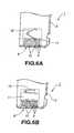
- the projections 10may be formed inside the concavity 9 to define sockets for the terminals 5 as shown in FIGS. 6A and 6B .
- the projections 10can positively protect the terminals 5 by preventing touch to them even when the shutter member 11 is inadvertently opened with the memory card 1 not yet inserted into the receptacle.
- FIG. 6Ashows the top opening of the concavity 9 being covered or closed by the shutter member 11 while FIG. 6B shows the shutter member 11 moved away from on the concavity 9 and thus the concavity 9 being open at the top thereof.
- FIGS. 7 and 8show a memory card receptacle, generally indicated with a reference 20, adapted to receive the memory card 1 having been described in the foregoing.
- the memory card 1 constructed as in the aboveis used, it is inserted in the receptacle 20 as shown in FIGS. 7 and 8 to record or reproduce information signal into or from the memory card 1.
- the memory card receptacle 20has an opening 21 formed at the front end thereof, through which the memory card 1 is inserted into the receptacle 20. Also, the receptacle 20 has formed therein, in the inserting direction of the memory card 1 indicated with an arrow C in FIG. 7 , a memory card receiving concavity 22 axially extending from the opening 21 to a depth in the receptacle 20 and in which the memory card 1 is received. There are disposed inside this memory card receiving concavity 22 tips of a plurality of terminals 23 electrically connected to an external system as shown in FIG. 7 .
- the terminals tips 23are formed by punching a thin metal sheet, for example.
- the terminals 23are supported with the bases thereof buried in the body of the receptacle 20 as shown. Therefore, the terminals 23 also work as leaf springs which depress the terminals 5 of the memory card 1 inserted in the receptacle 20.
- the terminals 23have each a contact point 23a formed near the free ends thereof inside the receiving concavity 22 and which are put into contact with the terminals 5 of the memory card 1.
- the terminals 23 of the receptacle 20are equal in number to the terminals 5 of the memory card 1. In this embodiment of the receptacle 20, nine terminals 23 for the nine terminals 5 of the memory card 1 are provided in the receiving concavity 22.
- the terminals 23 disposed in the receiving concavity 22that is to say, in positions corresponding to the forward end of the memory card 1 when inserted in the receptacle 20, projections 24 which will slide on the terminals 5 of the memory card 1 when the latter is inserted into the receptacle 20.
- the projections 24are equal in number to the terminals 5 of the memory card 1 similarly to the terminals 23 of the receptacle 20.
- the projections 24are provided ahead of the terminals 23. In this embodiment of the receptacle 20, nine projections 24 are thus provided for the nine terminals 5.
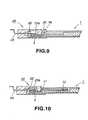
- the projections 24slide on the terminals 5 of the memory card 1 before they get into contract with the terminals 23 as shown in FIG. 9 .
- the projections 24will let out dust or the like from inside the concavity 9 of the memory card 1 over the inclined wall 9a of the concavity 9 of the memory card 1.
- the projections 24move ahead of the terminals 23 and slide on the terminals 5 of the memory card 1. After the projections 24 let out dust or the like from on the terminals 5, the terminals 23 get into contact with the terminals 5 of the memory card 1. Thus, the terminals 23 and 5 are electrically connected to one another in a positive manner.
- the plurality of projections 24is provided ahead of the terminals 23 correspondingly to the terminals 5, respectively, of the memory card 1 in such a manner that the projections 24 can be well fitted into the sockets defined by the projections 10 inside the concavity 9 of the memory card 1 for the respective terminals 5.
- the receptacle 20can suitably receive the memory card 1 of such a structure as well as the memory card 1 having the concavity 9 of which the space is similarly trisected by the projections 10.
- the receptacle 20can well receive the memory card 1 having the concavity 9 of which the top opening can be covered by the shutter member 11 for protection of the terminals 5.
- the projections 24abut at the front end faces thereof on the forward end of the shutter member 11 which will thus be moved open as the memory card 1 is further inserted into the receptacle 20, as seen from FIG. 10 .
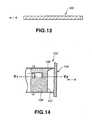
- the receptacle 20can receive a memory card having only the concavity 9 formed at the forward end, in the inserting direction, of the card body 2, and the terminals 5 disposed in the concavity 9, as shown in FIG. 11 , with the projections 10 and shutter member 11 not provided.
- the memory card receptacle 20is versatile as having been described in the above, namely, it can be universally applied without being restricted by the shape of the memory card 1.
- memory cardmay also be constructed as will be discussed below:
- the memory cardis generally indicated with a reference 100. It has a generally rectangular flat shape having four corners 101a, 101b, 101c and 102. Of these four corners, one (101a) of the corners at the forward end, in the inserting direction, of the memory card 100 indicated with the arrow D, and both the corners 101b and 101c at the rear end, in the inserting direction of, the memory card 100 indicated with the arrow D, are chamfered much more than the remaining corner, or the latter is not chamfered.
- the memory card 100is so shaped that it can be judged based on the position of the corner 102 whether the memory card 100 being inserted into the receptacle is positioned correctly or incorrectly, whereby the memory card 100 can be prevented from incorrectly being inserted into the receptacle.
- the remaining corner 102 at the forward end, in the inserting direction, of the memory card 100 indicated with the arrow Dis not chamfered while the other three corners 101a, 101b and 101c are chamfered to have an arcuate form, for example. Furthermore, the corner 101a is rounded much more than the other two corners 101b and 101c as shown in FIG. 12 .
- FIG. 14is a plan view of an example of the receptacle 103
- FIG. 15is a sectional view taken along the line Y 1 -Y 2 of the receptacle 103 in FIG. 14
- FIG. 14is a plan view, hatching is made somewhere therein for better understanding of the relation between the members of the receptacle 103.
- the receptacle 103has formed at the forward end thereof an opening 104 through which the memory card 100 is to be inserted, formed therein a receiving concavity 105 extending from the opening 104 along the inserting direction of the memory card 100 indicated with an arrow E, and provided at the innermost portion of the opening 104 an incorrect insertion-preventive member 106 extending in the inserting direction of the memory card 100 indicated with the arrow E.
- the incorrect insertion-preventive member 106has at the opening 104 of the receptacle 103 a front end face 107 extending generally perpendicular to the inserting direction of the memory card 100, and a projection 108 formed at one of the lateral ends of the front end face 107.
- the projection 108has an oblique surface 109 which becomes thinner and narrower as it goes from the front end face 107 toward the opening 104.
- the oblique surface 109detects the corner 102 of the memory card 100.
- the incorrect insertion-preventive member 106is pivoted and forced clockwise in the plane of FIG. 15 under the action of a coil spring 110.
- the member 106closes the opening 104 to block dust or the like from coming into the receptacle 103.
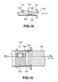
- FIGS. 16 , 17 and 18show the memory card 100 correctly inserted in the receptacle 103.
- the memory card 100As the memory card 100 is inserted from the opening 104 in the direction of arrow E, it will abut at the corner 102 thereof on the projection 108 formed on the incorrect insertion-preventive member 106 as shown in FIG. 16 . Then the upper end of the corner 102 slides on the oblique surface 109 of the projection 108 as shown in FIG. 17 and urges up the incorrect insertion-preventive member 106. Eventually the corner 102 will allow the incorrect insertion-preventive member 106 to escape as shown in FIG. 18 and thus the memory card 100 is allowed to go into place in the receptacle 103.
- FIGS. 19 and 20show the memory card 100 being inserted in a wrong direction into the receptacle 103.
- the rounded corner 101awill not abut on the projection 108 of the incorrect insertion-preventive member 106 but at the forward end, in the inserting direction, thereof on the front end face 107 of the incorrect insertion-preventive member 106. Since the front end face 107 of the member 106 is formed generally perpendicular to the inserting direction of the memory card 100 indicated with the arrow E, the forward end of the memory card 100 will be caught by the projection 108 and thus cannot urge up the incorrect insertion-preventive member 106.
- the corner 101awill not allow the incorrect insertion-preventive member 106 to escape, so that the memory card 100 cannot be inserted deep into place in the receptacle 103.
- FIGS. 19 and 20show an example in which the memory card 100 is inserted upside down in the receptacle 103. Also in this case, the corners 101b and 101c will not allow the incorrect insertion-preventive member 106 to escape, so that the memory card 100 cannot be inserted deep into place in the receptacle 103. Therefore, it is only when the memory card 100 is inserted correctly that the memory card 100 can be inserted deep into place in the receptacle 103. Thus, the memory card 100 can be prevented from being incorrectly inserted into the receptacle 103.
- the corners 101a, 101b and 101chave only to be formed not to abut on the projection 108 of the incorrect insertion-preventive member 106, and thus may be shaped to have any flat form.
- the cornersmay be chamfered in different sizes as well as in various shapes such as arcuate, linear or the like as shown in FIG. 21 . Such variations in chamfered size and shape of the corners will also give a variation to the memory card design.
- the memory card according to the present inventionmay be constructed as will be discussed below:
- This memory card 120is generally rectangular in shape, and cut at 121 at the bottom edge of the forward end thereof in the inserting direction indicated with an arrow F as will be seen from FIG. 23 .
- the cut 121extends over the entire forward-end short side of the memory card 120, and provides an oblique flat end face.
- FIG. 24is a plan view of an example of the construction of the receptacle 122
- FIG. 25is a sectional view taken along the line W 1 -W 2 of the receptacle 122 shown in FIG. 24 .
- the receptacle 122has formed at the forward end thereof an opening 123 through which the memory card 120 is to be inserted, formed therein a receiving concavity 124 extending from the openings 123 in the inserting direction of the memory card 120 indicated with an arrow G, and provided at the innermost portion of the opening 123 an incorrect insertion-preventive member 125 extending in the inserting direction of the memory card 120 indicated with the arrow G.
- the incorrect insertion-preventive member 125has a blocking plate 127 having a first face 126 generally perpendicular to the inserting direction of the memory card 120 indicated with the arrow G, and a projection 129 provided at the upper end of the blocking plate 127 on the side of the opening 123 and which has a second face 128 generally parallel to the inserting direction of the memory card 120.
- the incorrect insertion-preventive member 125is pivoted and forced clockwise in the plane of FIG. 25 under the action of a coil spring 130.
- the member 125closes the opening 123 to block dust or the like from coming into the receptacle 122.
- the incorrect insertion-preventive member 125is rotated about 90 deg. counterclockwise (in the plane of Figure) against the action of the coil spring 130 and the first face 126 will be generally parallel to the inserting direction of the memory card 120.
- the forward end of the memory card 120will slide at the oblique face of the cut 121 onto the projection 129 to depress the incorrect insertion-preventive member 125, as shown in FIG. 26 .
- the cut 121will allow the incorrect insertion-preventive member 106 to escape as shown in FIG. 27 and thus the memory card 120 is allowed to go deep into place in the receptacle 122.
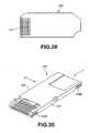
- the memory card 120When the memory card 120 is inserted in a wrong direction into the receptacle 122, that is, when the cut 121 is not positioned down as shown i n FIG. 28 , the memory card 120 will abut at the forward end thereof onto the second face 128 of the projection 129. Since the second face 128 is generally perpendicular to the inserting direction of the memory card 120 indicated with the arrow G, the forward end of the memory card 120 is caught by the projection 129 so that it cannot depress the incorrect insertion-preventive member 125. Therefore, when the memory card 120 is inserted in a wrong direction, the incorrect insertion-preventive member 125 cannot be allowed to escape to insert the memory card 120 deep into place in the receptacle 122.
- FIG. 28shows the memory card 120 being inserted upside down into the receptacle 122. Also when the memory card 120 is inserted in a reverse direction, the incorrect insertion-preventive member 125 cannot be allowed to escape to insert the memory card 120 deep into place in the receptacle 122. Therefore it is only when the memory card 120 is inserted correctly that it can be inserted deep into place in the receptacle 122. Thus, it is possible to prevent incorrect insertion of the memory card 120.
- the cut 121has only to be formed to a size over which the projection 129 can be slid to depress the incorrect insertion-preventive member 125. Therefore, for the purpose of preventing an incorrect insertion of the memory card 120, the corners thereof has only to be shaped to have any flat form.
- the memory card 120may be chamfered at the corners thereof in different sizes as well as in various shapes such as arcuate, linear or the like, as shown in FIG. 29 . Such variations in chamfered size and shape of the corners will also give a variation to the memory card design.
- the memory card according to the present inventionmay be designed for fitting onto the top of the receptacle
- FIG. 30shows an example of the memory card of such design.
- the memory cardis generally indicated with a reference 140.
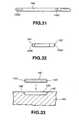
- FIG. 31is a view of the memory card 140 from a direction H in FIG. 30
- FIG. 32is a view of the memory card 140 from a direction I in FIG. 30 .
- the memory card 140has a generally rectangular flat shape.
- the memory card 140has recesses 143a and 143b formed at end portions, respectively, of a first longitudinal side 141 thereof and also recesses 143c and 143d formed at end portions, respectively, of a second longitudinal side 142 parallel to the first longitudinal side, as shown in FIG. 31 .
- the memory card 140can be fitted into a receptacle 144 using the recesses 143a to 143d thereof as will be described below.
- the receptacle 144has formed on the top thereof a concavity 145, for example, in which the memory card 140 is to be fitted.
- the concavity 145is open at the top thereof, and projections 146 are formed on side walls, respectively, of the concavity 145.
- the memory card 140can be fitted to the receptacle 144 with the projections 146 of the receptacle 144 engaged in the recesses 143 (143a to 143d) of the memory card 140, as shown in FIG. 34 .
- the memory card 140can be directly set in a recording/reproducing apparatus. Also, the memory card 140 may be fitted in an adapter having a shape of a flexible disk, PC card or the like, for example, and then the adapter in which the memory card 140 is fitted be set in the recording/reproducing apparatus.
- the top cover of the receptacleis unnecessary and the receptacle can be designed thinner than a one which is to receive the memory card therein so that the receptacle can be designed more compact.
- the above-mentioned adapter destined to have the memory card fitted therein for setting into a recording/reproducing apparatuscan be designed to have a reduced thickness.
Landscapes
- Engineering & Computer Science (AREA)
- Physics & Mathematics (AREA)
- General Physics & Mathematics (AREA)
- Theoretical Computer Science (AREA)
- Computer Hardware Design (AREA)
- Microelectronics & Electronic Packaging (AREA)
- Artificial Intelligence (AREA)
- Computer Vision & Pattern Recognition (AREA)
- Coupling Device And Connection With Printed Circuit (AREA)
- Credit Cards Or The Like (AREA)
- Details Of Connecting Devices For Male And Female Coupling (AREA)
- Connector Housings Or Holding Contact Members (AREA)
Description
- The present invention relates to a memory card designed for reception in a memory card receptacle and into or from which information signal is to be written or read, and the memory card receptacle.
- A well-known memory card incorporating memory chips in which information signals are stored is provided with terminals which are to electrically be connected with an external system. The memory card is supplied with a voltage through the terminals and also delivers and receives information signal to and from the internal memory chips through the terminals.
- Since the terminals for connection of the memory card to an external system are also electrically connected to the internal memory chips, they should be protected from being touched when the memory card is used. More particularly, if the terminals are directly touched, a static electricity will take place in them, which however is a rare case, and be carried from the terminals to the memory chips which thus will possibly be broken down. To avoid this, the terminals should be protected against easy access to them from outside to prevent such a breakdown due to a static electricity.
- Also, the memory card of this type is featured by its transportability. So, it has been tried to design more compact memory cards for the convenience of portability. Thus, along with the more compact design of the memory card itself, its terminals have been designed thinner and arranged at reduced intervals.
- Such thin, closely disposed terminals for connection an external system will possibly be deformed and broken even if just lightly touched.
- To prevent the terminals from being deformed or broken down, a memory card of this type has been proposed in which such terminals are buried inside in the memory card body and small holes communicating with the terminals are formed in the memory card body so that the terminals are exposed to outside only through the holes, or in which a concavity is formed in a forward end portion of the memory card body in the card inserting direction and terminals are disposed in the bottom of the concavity for protection of them.
- However, the memory card in which the small holes are formed in the card body for the terminals to be exposed to outside is hard to disconnect from the receptacle if the holes are clogged with dust or the like. When the memory card is inserted into the receptacle with the holes left clogged with dust, no positive connection with the receptacle can be attained and also the terminals of the receptacle may possibly be deformed as the case may be.
- Further, the above memory card is apt to have a complicated structure and is manufactured with large costs. Therefore, the conventional memory card is not suitable for mass production.
- Also, in the memory card having formed in the body thereof the concavity in which the terminals are disposed, the protection of the terminals cannot be protected to a satisfactory extent if the concavity is improperly shaped. If the concavity is not shaped for a satisfactory protection of the terminals, dust or the like is likely to heap or stay in the corners of the concavity and block the terminals of the memory card from secure connection with those of the receptacle.
- Further a memory card has been proposed which is cut at one of the corners of a generally rectangular body thereof to prevent the memory card from being inserted incorrectly (in a wrong direction or posture) into a memory card receptacle. In this case, however, the memory card cannot be designed to have a variety of shapes by chamfering or rounding, for example, the other three corners.
- Document
WO 95/31793 US discloses a system for handling variable digital information comprising a key having an active integrated circuit component with leads extending therefrom, a battery for powering the component, unplated leads extending from the component to both the battery and to one edge of the key, and a container for sealing the component, battery and leads except at the edge of the container.Patent 5 157.244- The present invention has an object to overcome the above-mentioned drawbacks of the prior art by providing a memory card having a simple structure, adapted to positively protect terminals thereof and easily let out dust or the like from inside to attain a positive connection with a memory card receptacle, and designable to have a variety of corner shapes, and the memory card receptacle.
- The present invention relates to a memory card connectable to an external apparatus, said memory card comprising:
- a card body incorporating memory chips,
- said card body having a top, a forward end and a lateral side,
- said top of the card body having a concavity open at the forward end,
- said concavity having an inclined inner wall perpendicular to the inserting direction of the card body;
- a connector portion for communicating with said external apparatus, said connector portion having a plurality of terminals disposed side by side in the concavity in an inserting direction of the card body, said plurality of terminals having a signal input/output terminal for digital signal input or digital signal output for a serial interface with said external apparatus and a reserved terminal for signal input or signal output, said reserved terminal being used only for a parallel interface with said external apparatus, said reserved terminal is used with said signal input/output terminal for signal input or signal output when said reserved terminal is used for the parallel interface with said external apparatus; and
- insulating projections formed between adjacent terminals disposed in the concavity.
- Favorably said card body and said projections are formed of the same material.
- Favorably said card body has a cut provided only at a corner of said forward end of said card body for preventing said electric device from being incorrectly inserted into a receptacle therefor, said cut being formed obliquely to said inserting direction of the card body such that a corner otherwise disposed at said forward end and said lateral side is removed.
- Favorably said card body has a cut provided at a corner of said forward end of said card body, said cut being formed obliquely to said inserting direction of the card body, and said top of the card body having a notch therein disposed in the vicinity of the intersection of said top, said forward end and said lateral side, such that a corner otherwise disposed at said forward end and said lateral side is removed, and said notch ends at said cut.
- Favorably said card body has a cut that extends over said forward end of the card body, said cut being formed obliquely to said inserting direction of the card body to form an angle in the leading edge formed by said top and forward end of said card body, said angle extending over said projections.
- Favorably said card body has a depression formed in said lateral side and in said top of said card body and extending downward from the top of said card body, the depth of said depression being approximately half the thickness of said card body, for preventing disengagement of the card body from a receptacle therefor.
- Favorably said card body has formed on a lateral side thereof recesses for fitting in a receptacle therefor.
- Favorably said plurality of terminals include a sync signal input terminal, a status signal input terminal and a voltage supply terminal.
- Favorably a central terminal is a ground terminal.
- Favorably a system having a memory card according to the present invention and a receptacle to receive said memory card; said receptacle comprising:
- a body having a receiving concavity open at an end of the body and in which said memory card is introduce and
- a plurality of terminals to be connected to said terminals of said memory card, respectively.
- Favorably said card body has a cut provided at a corner of said forward end of said card body, said cut being formed obliquely to said inserting direction of the card body, and said top of the card body having a notch therein disposed in the vicinity of the intersection of said top, said forward end and a lateral side, such that a corner otherwise disposed at said forward end and said lateral side is removed, and said notch ends at said cut.
- Favorably said card body has a cut that extends over said forward end of the card body, said cut being formed obliquely to said inserting direction of the card body to form an angle in the leading edge formed by said top and forward end of said card body, said angle extending over said projections.
- Favorably said card body has a depression formed in a lateral side and in said top of said card body and extending downward from the top of said card body, the depth of said depression being approximately half the thickness of said card body, for preventing disengagement of the card body from a receptacle therefor.
- Favorably said card body has recesses formed on a lateral side thereof for fitting in said receptacle.
- Favorably said plurality of terminals of said memory card include a sync signal input terminal, a status signal input terminal and a voltage supply terminal.
- Favorably a central terminal of said memory card is a ground terminal.
- In this memory card, the projections are formed in the concavity to define sockets in each of which a terminal is disposed, whereby the terminals thus disposed in the concavity can be protected against access or touch from outside.
- Since the concavity has the inclined inner wall, dust or the like, if any, can easily be let out from on the concavity wall when the memory card is inserted into a memory card receptacle.
- An example of the present provides a memory card comprising a body, a concavity formed in the card body and open at the top and forward end, in the inserting direction, of the card body, and terminals disposed in the concavity. The memory card has also a shutter member which opens and closes the concavity, and the inner wall of the concavity perpendicular to the inserting direction of the memory card is inclined.
- When the memory card is not inserted into a memory card receptacle, the concavity is closed by the shutter member so that the terminals disposed inside the concavity cannot be accessed or touched from outside.
- When the memory card is inserted into a memory card receptacle, dust or the like is removed to outside from the inclined wall of the concavity.
- When the memory card is inserted into the receptacle, the projections go ahead of the receptacle terminals and slide on the memory card terminals to let out dust or the like from on the memory card receptacle.
- These objects and other objects, features and advantages of the present intention will become more apparent from the following detailed description of the preferred embodiments of the present invention when taken in conjunction with the accompanying drawings, of which:
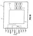
FIG. 1A shows the construction of a first embodiment of the memory card according to the present invention;FIG. 1B shows the construction of a second embodiment of the memory card of the present invention;FIG. 2 is a perspective view of the memory card inFIG. 1A ;FIG. 3 is a bottom view of the memory card inFIG. 1A ;FIG. 4 is a perspective view of a third embodiment of the memory card according to the present invention;FIG. 5A is a plan view of an example of the memory card according to the present invention, showing the essential portion thereof with a shutter member placed to close or cover the concavity;FIG. 5B is a plan view of the memory card inFIG. 5A , showing the essential portion thereof with the shutter member placed to open the concavity;FIG. 6A is a plan view of another example of the memory card according to the present invention, showing the essential portion thereof with a shutter member placed to close the concavity;FIG. 6B is a plan view of the memory card inFIG. 6A , showing the essential portion thereof with the shutter member placed to open the concavity;FIG. 7 is a sectional view of a first embodiment of the memory card receptacle according to the present invention;FIG. 8 is a front view of the memory card receptacle inFIG. 7 ;FIG. 9 is a sectional view of the receptacle inFIG. 7 in which the memory card is received;FIG. 10 is a sectional view of the receptacle inFIG. 7 in which another memory card of the present invention is received;FIG. 11 is a plan view showing the essential portion of another memory card of the present invention;FIG. 12 is a plan view showing an example of the shape of the memory card of the present invention;FIG. 13 is a sectional view taken along the line X1-X2 of the memory card inFIG. 12 ;FIG. 14 is a plan view showing an example of the construction of the receptacle of the present invention in which the memory card of the present invention is received;FIG. 15 is a sectional view taken along the line Y1-Y2 inFIG. 14 , showing the example of the construction of the receptacle of the present invention;FIG. 16 is a plan view showing the memory card being correctly inserted in the receptacle;FIG. 17 is a sectional view taken along the line Y3-Y4 inFIG. 16 , showing the memory card being correctly inserted in the receptacle;FIG. 18 is also a sectional view taken along the line Y3-Y4 inFIG. 16 , showing the memory card correctly inserted in the receptacle;FIG. 19 is a plan view showing the memory card being incorrectly inserted into the receptacle;FIG. 20 is a sectional view taken along the line Y5-Y6 inFIG. 19 , showing the memory card being incorrectly inserted into the receptacle;FIG. 21 is a plan view showing an example of the shape of the memory card of the present invention;FIG. 22 is a plan view showing an example of the shape of the memory card of the present invention;FIG. 23 is a sectional view of the memory card, taken along the line Z1-Z2 inFIG. 22 ;FIG. 24 is a plan view showing an example of the construction of the receptacle of the present invention in which the memory card of the present invention is inserted;FIG. 25 is a sectional view of the receptacle, taken along the line W1-W2 inFIG. 24 ;FIG. 26 is a sectional view showing the memory card being correctly inserted in the receptacle;FIG. 27 is also a sectional view showing the memory card being correctly inserted in the receptacle;FIG. 28 is a sectional view showing the memory card being incorrectly inserted into the receptacle;FIG. 29 is a plan view showing an example of the shape of the memory card of the present invention;FIG. 30 is a perspective view showing an example of the shape of the memory card of the present invention;FIG. 31 is a view of the memory card from a point H inFIG. 30 ;FIG. 32 is a view of the memory card from a point I inFIG. 30 ;FIG. 33 is a sectional view of the memory card of the present invention inserted in the receptacle of the present invention; andFIG. 34 is a sectional view of the memory card of the present invention inserted in the receptacle of the present invention.- A memory card according to the present invention is generally indicated with a
reference 1. - It is a storage medium which is inserted, for use, into a receptacle of an external system such as a computer, audio equipment, etc. for read or write of information signal between the memory card and external system thus connected to the memory card. As shown in
FIGS. 1A and1B , thememory card 1 has acard body 2 incorporating a plurality ofmemory chips 3 such as flash memory, etc. to store information signal, and a controlling integrated circuit 4 (will be referred to as "controlling IC" hereafter) to write or read information signal into or from thememory chips 3. - Further, the
memory card 1 hasterminals 5 for connection to an external system as shown inFIG. 2 . When thememory card 1 is inserted into a memory card receptacle, theterminals 4 are electrically connected to those of the memory card receptacle to supply a voltage to the controllingIC 4 and transfer information signal and various control signals between thememory card 1 and the external system. Thememory card 1 adopts a serial interface and theterminals 5 provided count nine in number. - The
card body 2 is a thin, flat, rectangular card made of a synthetic resin, for example. Thememory card 1 of this embodiment adopts the serial interface and is designed to have nineterminals 5, and thus thecard body 2 itself is small. As shown inFIG. 3 , thecard body 2 has a short side L1 of which the length is smaller than a half of the length L2 of the long side. For example, L1 is 21.5 mm while L2 is 50 mm, and the thickness of thecard body 2 is 2.8 mm. - The
card body 2 has an inadvertent erasure-preventive member 6 attached to the rear end thereof in the inserting direction of thecard body 2 indicated with an arrow A inFIGS. 2 and3 . The inadvertent erasure-preventive member 6 is engaged on an inadvertent erasure-preventive switch (not illustrated) housed in thecard body 2. Sliding themember 6 in a direction perpendicular to the inserting direction of thecard body 2 will turn on/off the inadvertent erasure-preventive switch. Also, thecard body 2 has formed on a lateral side thereof parallel to the inserting direction of thecard body 2 an arcuate locking cut 7 which prevents thememory card 1 from being freely disengaged from the memory card receptacle once thememory card 1 is inserted in the receptacle. When thememory card 1 is inserted into the receptacle, a mating locking projection (not illustrated) provided on the receptacle is engaged in this locking cut 7 to prevent thememory card 1 from being freely disengaged from the receptacle. - At one lateral end in the inserting direction, the
card body 2 is cut (at 8) obliquely with respect to the inserting direction of thecard body 2. Thiscut 8 is formed to prevent thememory card 1 from being incorrectly inserted into the receptacle. Further, thecard body 2 has formed aconcavity 9 formed at the forward end, in the inserting direction, thereof. - The
concavity 9 is formed open to the forward end of thecard body 2 and extends longitudinally from the forward end, in the inserting direction, of thecard body 2. Theconcavity 9 is deep a predetermined step from the top surface of thecard body 2, and thus it is defined by three walls and a bottom 9b. One 9a of the walls of theconcavity 9, inner and parallel to the forward open end, is inclined at a predetermined angle with respect to the bottom 9b. - Because of the forward open end and inclined
inner wall 9a of theconcavity 9 in thememory card 1, dust or the like in theconcavity 9 can be easily let out when thememory card 1 is inserted into the receptacle. - In the
concavity 9, there is disposed a plurality ofterminals 5 for connection to corresponding terminals of the receptacle when thecard body 2 is inserted into the receptacle. Theterminals 5 are formed by punching a thin metal sheet or from a pattern of a printed wiring board. They are laid side by side on the bottom 9b of theconcavity 9 in the inserting direction of thecard body 2, and exposed to outside. - Since the
memory card 1 of the present invention adopts the serial interface, theterminals 5 thus provided count nine in number. Namely, the nineterminals 5 disposed in theconcavity 9 of thememory card 1 include a digital signal input/output terminal, a sync signal input terminal, a status signal input terminal, four voltage supply terminals, and two reserved terminals. - Further, there are formed between the
terminals 5 inside theconcavity 9projections 10 serving to prevent an access or touch to theterminals 5 from outside. As shown inFIG. 2 , for example, theprojections 10 extend between the open forward end and theinner wall 9a of theconcavity 9 parallel to the forward end, and count two in number to trisect the space in theconcavity 9 in this case. Threeterminals 5 are disposed in three sockets, respectively, defined by theprojections 10 thus formed inside theconcavity 9. - The
projections 10 provided in theconcavity 9 of thememory card 1 will prevent the user from inadvertently touching theterminals 5 when inserting thememory card 1 into the receptacle. Theterminals 5 can be thus protected. - The central one of the
terminals 5 disposed in the three sockets defined by theprojections 10 in theconcavity 9 should desirably be connected to the ground potential. - Since the
memory card 1 is connected at the central one of theterminals 5 to the ground potential, even when the user's finger is put into theconcavity 9, it will touch the grounded one of theterminals 5 so that a static electricity, if any, caused by touching theterminals 5 with the finger will be connected to the earth and thus thememory chip 3 will not be damaged by the static electricity. - As shown in
FIG. 4 , thememory card 1 may have formed in theconcavity 9 a corresponding number of theprojections 10 to a desired number of theterminals 5, and have theterminals 5 disposed in the sockets, respectively, defined by theprojections 10 in theconcavity 9. Theprojections 10 thus formed for theterminals 5 will positively prevent theterminals 5 being accessed or touched from outside. - It should be noted that ten
terminals 10 may be provided in thememory card 1 as shown inFIG. 1B . Three of these tenterminals 5 may be reserved ones. In thememory card 1 with such tenreserved terminals 5, the threereserved terminals 5 can be used as signal input or output terminals to permit a parallel interface using a total of four signal input or output terminals including the aforementioned digital signal input/output terminal. - The present invention has been described in the foregoing concerning an embodiment in which the
projections 10 are formed in the concavity to prevent access or touch to theterminals 5. However, thememory card 1 according to the present invention may comprise ashutter member 11 which is moved to open or close theconcavity 9. As shown inFIG. 5A , when thememory card 1 is not inserted in the receptacle, theshutter member 11 closes theconcavity 9 to prevent access to theterminals 5. In this embodiment, thecard body 2 has formed therein, over an axial distance substantially corresponding to the axial length of theconcavity 9 from theinner wall 9a parallel to the forward end of theconcavity 9, an indentation in which theshutter member 11 is slidable. - The
shutter member 11 is a rectangular plate made of a synthetic resin, for example, and slightly larger in area than the top opening of theconcavity 9, and it is installed at the forward end of thecard body 2 to be movable in the inserting direction. While thememory card 1 is not inserted in the receptacle, theshutter member 11 is pressed to the forward end of theconcavity 9 to cover the top opening of theconcavity 9. - When the
memory card 1 is inserted into the receptacle, it will abut at the forward end thereof on projections of the receptacle as will be further described later. As shown inFIG. 5B , as thememory card 1 is inserted, theshutter member 11 is pushed in by the projections against the force of aspring member 12 in the direction of arrow B, and moved into the above-mentioned indentation so that theconcavity 9 will be open at the top thereof. - When the
memory card 1 is not inserted into the receptacle, theconcavity 9 is covered by theshutter member 11, so that theterminals 5 are prevented from being accessed or touched from outside and thus protected. - In the
memory card 1 according to this embodiment as well, theinner wall 9a parallel to the forward open end of theconcavity 9 is inclined at a predetermined angle with respect to the bottom 9b. Also theshutter member 11 should desirably have an inclined forward end face. - The
memory card 1 has thus the inclinedinner wall 9a parallel to the forward open end of theconcavity 9 and the inclined forward end face of theshutter member 11 so that when thememory card 1 is inserted into the receptacle, dust or the like in theconcavity 9 can easily be let out from on the inclined wall and end face. - Also in this
memory card 1, theprojections 10 may be formed inside theconcavity 9 to define sockets for theterminals 5 as shown inFIGS. 6A and 6B . Thus, theprojections 10 can positively protect theterminals 5 by preventing touch to them even when theshutter member 11 is inadvertently opened with thememory card 1 not yet inserted into the receptacle.FIG. 6A shows the top opening of theconcavity 9 being covered or closed by theshutter member 11 whileFIG. 6B shows theshutter member 11 moved away from on theconcavity 9 and thus theconcavity 9 being open at the top thereof. FIGS. 7 and 8 show a memory card receptacle, generally indicated with areference 20, adapted to receive thememory card 1 having been described in the foregoing. When thememory card 1 constructed as in the above is used, it is inserted in thereceptacle 20 as shown inFIGS. 7 and 8 to record or reproduce information signal into or from thememory card 1.- As shown, the
memory card receptacle 20 has anopening 21 formed at the front end thereof, through which thememory card 1 is inserted into thereceptacle 20. Also, thereceptacle 20 has formed therein, in the inserting direction of thememory card 1 indicated with an arrow C inFIG. 7 , a memorycard receiving concavity 22 axially extending from theopening 21 to a depth in thereceptacle 20 and in which thememory card 1 is received. There are disposed inside this memorycard receiving concavity 22 tips of a plurality ofterminals 23 electrically connected to an external system as shown inFIG. 7 . - The
terminals tips 23 are formed by punching a thin metal sheet, for example. Theterminals 23 are supported with the bases thereof buried in the body of thereceptacle 20 as shown. Therefore, theterminals 23 also work as leaf springs which depress theterminals 5 of thememory card 1 inserted in thereceptacle 20. Theterminals 23 have each acontact point 23a formed near the free ends thereof inside the receivingconcavity 22 and which are put into contact with theterminals 5 of thememory card 1. - The
terminals 23 of thereceptacle 20 are equal in number to theterminals 5 of thememory card 1. In this embodiment of thereceptacle 20, nineterminals 23 for the nineterminals 5 of thememory card 1 are provided in the receivingconcavity 22. - Further, there are provided ahead of the
terminals 23 disposed in the receivingconcavity 22, that is to say, in positions corresponding to the forward end of thememory card 1 when inserted in thereceptacle 20,projections 24 which will slide on theterminals 5 of thememory card 1 when the latter is inserted into thereceptacle 20. Theprojections 24 are equal in number to theterminals 5 of thememory card 1 similarly to theterminals 23 of thereceptacle 20. Theprojections 24 are provided ahead of theterminals 23. In this embodiment of thereceptacle 20, nineprojections 24 are thus provided for the nineterminals 5. When thememory card 1 is inserted into thereceptacle 20, theprojections 24 slide on theterminals 5 of thememory card 1 before they get into contract with theterminals 23 as shown inFIG. 9 . Theprojections 24 will let out dust or the like from inside theconcavity 9 of thememory card 1 over theinclined wall 9a of theconcavity 9 of thememory card 1. - When the
memory card 1 is inserted into thememory card receptacle 20, theprojections 24 move ahead of theterminals 23 and slide on theterminals 5 of thememory card 1. After theprojections 24 let out dust or the like from on theterminals 5, theterminals 23 get into contact with theterminals 5 of thememory card 1. Thus, theterminals - In the
receptacle 20, the plurality ofprojections 24 is provided ahead of theterminals 23 correspondingly to theterminals 5, respectively, of thememory card 1 in such a manner that theprojections 24 can be well fitted into the sockets defined by theprojections 10 inside theconcavity 9 of thememory card 1 for therespective terminals 5. Thus, thereceptacle 20 can suitably receive thememory card 1 of such a structure as well as thememory card 1 having theconcavity 9 of which the space is similarly trisected by theprojections 10. - Further, the
receptacle 20 can well receive thememory card 1 having theconcavity 9 of which the top opening can be covered by theshutter member 11 for protection of theterminals 5. In this example, when thememory card 1 having theshutter member 11 is inserted into thereceptacle 20, theprojections 24 abut at the front end faces thereof on the forward end of theshutter member 11 which will thus be moved open as thememory card 1 is further inserted into thereceptacle 20, as seen fromFIG. 10 . - Also it is of course that the
receptacle 20 can receive a memory card having only theconcavity 9 formed at the forward end, in the inserting direction, of thecard body 2, and theterminals 5 disposed in theconcavity 9, as shown inFIG. 11 , with theprojections 10 andshutter member 11 not provided. - The
memory card receptacle 20 is versatile as having been described in the above, namely, it can be universally applied without being restricted by the shape of thememory card 1. - It should now be noted that the memory card according to the present invention may also be constructed as will be discussed below:
FIG. 12 is a plan view of an example of the memory card, andFIG. 13 is a sectional view taken along the line X1-X2 of the memory card inFIG. 12 .- The memory card is generally indicated with a
reference 100. It has a generally rectangular flat shape having fourcorners memory card 100 indicated with the arrow D, and both thecorners memory card 100 indicated with the arrow D, are chamfered much more than the remaining corner, or the latter is not chamfered. Namely, thememory card 100 is so shaped that it can be judged based on the position of thecorner 102 whether thememory card 100 being inserted into the receptacle is positioned correctly or incorrectly, whereby thememory card 100 can be prevented from incorrectly being inserted into the receptacle. - As mentioned above, the remaining
corner 102 at the forward end, in the inserting direction, of thememory card 100 indicated with the arrow D is not chamfered while the other threecorners corner 101a is rounded much more than the other twocorners FIG. 12 . - When used for information recording or reproduction, the
memory card 100 is inserted into areceptacle 103 as shown inFIGS. 14 and15 .FIG. 14 is a plan view of an example of thereceptacle 103, andFIG. 15 is a sectional view taken along the line Y1-Y2 of thereceptacle 103 inFIG. 14 . AlthoughFIG. 14 is a plan view, hatching is made somewhere therein for better understanding of the relation between the members of thereceptacle 103. - The
receptacle 103 has formed at the forward end thereof anopening 104 through which thememory card 100 is to be inserted, formed therein a receivingconcavity 105 extending from theopening 104 along the inserting direction of thememory card 100 indicated with an arrow E, and provided at the innermost portion of the opening 104 an incorrect insertion-preventive member 106 extending in the inserting direction of thememory card 100 indicated with the arrow E. - The incorrect insertion-
preventive member 106 has at theopening 104 of the receptacle 103 afront end face 107 extending generally perpendicular to the inserting direction of thememory card 100, and aprojection 108 formed at one of the lateral ends of thefront end face 107. Theprojection 108 has anoblique surface 109 which becomes thinner and narrower as it goes from thefront end face 107 toward theopening 104. Theoblique surface 109 detects thecorner 102 of thememory card 100. - Further the incorrect insertion-
preventive member 106 is pivoted and forced clockwise in the plane ofFIG. 15 under the action of acoil spring 110. When thereceptacle 103 is not used, themember 106 closes theopening 104 to block dust or the like from coming into thereceptacle 103. FIGS. 16 ,17 and 18 show thememory card 100 correctly inserted in thereceptacle 103. As thememory card 100 is inserted from theopening 104 in the direction of arrow E, it will abut at thecorner 102 thereof on theprojection 108 formed on the incorrect insertion-preventive member 106 as shown inFIG. 16 . Then the upper end of thecorner 102 slides on theoblique surface 109 of theprojection 108 as shown inFIG. 17 and urges up the incorrect insertion-preventive member 106. Eventually thecorner 102 will allow the incorrect insertion-preventive member 106 to escape as shown inFIG. 18 and thus thememory card 100 is allowed to go into place in thereceptacle 103.FIGS. 19 and 20 show thememory card 100 being inserted in a wrong direction into thereceptacle 103. As thememory card 100 is inserted in the direction of arrow E, therounded corner 101a will not abut on theprojection 108 of the incorrect insertion-preventive member 106 but at the forward end, in the inserting direction, thereof on thefront end face 107 of the incorrect insertion-preventive member 106. Since thefront end face 107 of themember 106 is formed generally perpendicular to the inserting direction of thememory card 100 indicated with the arrow E, the forward end of thememory card 100 will be caught by theprojection 108 and thus cannot urge up the incorrect insertion-preventive member 106. Therefore, if thememory card 100 is incorrectly inserted into thereceptacle 103, thecorner 101a will not allow the incorrect insertion-preventive member 106 to escape, so that thememory card 100 cannot be inserted deep into place in thereceptacle 103.FIGS. 19 and 20 show an example in which thememory card 100 is inserted upside down in thereceptacle 103. Also in this case, thecorners preventive member 106 to escape, so that thememory card 100 cannot be inserted deep into place in thereceptacle 103. Therefore, it is only when thememory card 100 is inserted correctly that thememory card 100 can be inserted deep into place in thereceptacle 103. Thus, thememory card 100 can be prevented from being incorrectly inserted into thereceptacle 103.- For the purpose of preventing an incorrect insertion of the
memory card 100, thecorners projection 108 of the incorrect insertion-preventive member 106, and thus may be shaped to have any flat form. For example, the corners may be chamfered in different sizes as well as in various shapes such as arcuate, linear or the like as shown inFIG. 21 . Such variations in chamfered size and shape of the corners will also give a variation to the memory card design. - Also it should be noted that the memory card according to the present invention may be constructed as will be discussed below:
FIG. 22 shows, in the form of a plan view, an example of the memory card, andFIG. 23 is a sectional view taken along the line Z1-Z2 of the memory card shown inFIG. 22 .- This
memory card 120 is generally rectangular in shape, and cut at 121 at the bottom edge of the forward end thereof in the inserting direction indicated with an arrow F as will be seen fromFIG. 23 . Thecut 121 extends over the entire forward-end short side of thememory card 120, and provides an oblique flat end face. - For preventing incorrect insertion of the
memory card 120, it is judged based on the position of thiscut 121 whether thememory card 120 is inserted correctly or incorrectly, as will be discussed below. - For information recording or reproduction, the
memory card 120 is inserted into place in areceptacle 122 as shown inFIGS. 24 and25 .FIG. 24 is a plan view of an example of the construction of thereceptacle 122, andFIG. 25 is a sectional view taken along the line W1-W2 of thereceptacle 122 shown inFIG. 24 . Thereceptacle 122 has formed at the forward end thereof anopening 123 through which thememory card 120 is to be inserted, formed therein a receivingconcavity 124 extending from theopenings 123 in the inserting direction of thememory card 120 indicated with an arrow G, and provided at the innermost portion of the opening 123 an incorrect insertion-preventive member 125 extending in the inserting direction of thememory card 120 indicated with the arrow G. - As shown in
FIG. 25 , the incorrect insertion-preventive member 125 has a blockingplate 127 having afirst face 126 generally perpendicular to the inserting direction of thememory card 120 indicated with the arrow G, and aprojection 129 provided at the upper end of the blockingplate 127 on the side of theopening 123 and which has asecond face 128 generally parallel to the inserting direction of thememory card 120. - Further the incorrect insertion-
preventive member 125 is pivoted and forced clockwise in the plane ofFIG. 25 under the action of acoil spring 130. When thereceptacle 122 is not used, themember 125 closes theopening 123 to block dust or the like from coming into thereceptacle 122. - As the
memory card 120 is inserted into thereceptacle 122, the incorrect insertion-preventive member 125 is rotated about 90 deg. counterclockwise (in the plane of Figure) against the action of thecoil spring 130 and thefirst face 126 will be generally parallel to the inserting direction of thememory card 120. - When the
memory card 120 is correctly inserted into thereceptacle 122, that is to say, when thecut 121 formed at the bottom edge of the forward end of thememory card 120 is positioned down, the forward end of thememory card 120 will slide at the oblique face of thecut 121 onto theprojection 129 to depress the incorrect insertion-preventive member 125, as shown inFIG. 26 . Thus, thecut 121 will allow the incorrect insertion-preventive member 106 to escape as shown inFIG. 27 and thus thememory card 120 is allowed to go deep into place in thereceptacle 122. - When the
memory card 120 is inserted in a wrong direction into thereceptacle 122, that is, when thecut 121 is not positioned down as shown i nFIG. 28 , thememory card 120 will abut at the forward end thereof onto thesecond face 128 of theprojection 129. Since thesecond face 128 is generally perpendicular to the inserting direction of thememory card 120 indicated with the arrow G, the forward end of thememory card 120 is caught by theprojection 129 so that it cannot depress the incorrect insertion-preventive member 125. Therefore, when thememory card 120 is inserted in a wrong direction, the incorrect insertion-preventive member 125 cannot be allowed to escape to insert thememory card 120 deep into place in thereceptacle 122. FIG. 28 shows thememory card 120 being inserted upside down into thereceptacle 122. Also when thememory card 120 is inserted in a reverse direction, the incorrect insertion-preventive member 125 cannot be allowed to escape to insert thememory card 120 deep into place in thereceptacle 122. Therefore it is only when thememory card 120 is inserted correctly that it can be inserted deep into place in thereceptacle 122. Thus, it is possible to prevent incorrect insertion of thememory card 120.- Since it is judged based on the shape in the direction of the width of the
memory card 120 whether thememory card 120 is inserted correctly or incorrectly, thecut 121 has only to be formed to a size over which theprojection 129 can be slid to depress the incorrect insertion-preventive member 125. Therefore, for the purpose of preventing an incorrect insertion of thememory card 120, the corners thereof has only to be shaped to have any flat form. For example, thememory card 120 may be chamfered at the corners thereof in different sizes as well as in various shapes such as arcuate, linear or the like, as shown inFIG. 29 . Such variations in chamfered size and shape of the corners will also give a variation to the memory card design. - In addition to the above-mentioned structure designed for insertion into the receptacle, the memory card according to the present invention may be designed for fitting onto the top of the receptacle
FIG. 30 shows an example of the memory card of such design. In this case, the memory card is generally indicated with areference 140.FIG. 31 is a view of thememory card 140 from a direction H inFIG. 30 , andFIG. 32 is a view of thememory card 140 from a direction I inFIG. 30 . Thememory card 140 has a generally rectangular flat shape. Also thememory card 140 hasrecesses longitudinal side 141 thereof and also recesses 143c and 143d formed at end portions, respectively, of a secondlongitudinal side 142 parallel to the first longitudinal side, as shown inFIG. 31 .- The
memory card 140 can be fitted into areceptacle 144 using therecesses 143a to 143d thereof as will be described below. - As shown in
FIG. 33 , thereceptacle 144 has formed on the top thereof aconcavity 145, for example, in which thememory card 140 is to be fitted. Theconcavity 145 is open at the top thereof, andprojections 146 are formed on side walls, respectively, of theconcavity 145. For example, thememory card 140 can be fitted to thereceptacle 144 with theprojections 146 of thereceptacle 144 engaged in the recesses 143 (143a to 143d) of thememory card 140, as shown inFIG. 34 . - The
memory card 140 can be directly set in a recording/reproducing apparatus. Also, thememory card 140 may be fitted in an adapter having a shape of a flexible disk, PC card or the like, for example, and then the adapter in which thememory card 140 is fitted be set in the recording/reproducing apparatus. - In this case, since the memory card is fitted in a receptacle and then set in the recording/reproducing apparatus, the top cover of the receptacle is unnecessary and the receptacle can be designed thinner than a one which is to receive the memory card therein so that the receptacle can be designed more compact. Also, the above-mentioned adapter destined to have the memory card fitted therein for setting into a recording/reproducing apparatus can be designed to have a reduced thickness.
Claims (16)
- A memory card (1) connectable to an external apparatus, comprising:a card body (2) incorporating memory chips (3),said card body having a top, a forward end and a lateral side,said top of the card body having a concavity (9) open at the forward end,said concavity having an inclined inner wall (9a) perpendicular to the inserting direction of the card body;a connector portion for communicating with said external apparatus, said connector portion having a plurality of terminals (5) disposed side by side in the concavity in an inserting direction of the card body, said plurality of terminals having a signal input/output terminal for digital signal input or digital signal output for a serial interface with said external apparatus and a reserved terminal for signal input or signal output, said reserved terminal being used only for a parallel interface with said external apparatus, said reserved terminal is used with said signal input/output terminal for signal input or signal output when said reserved terminal is used for the parallel interface with said external apparatus; andinsulating projections (10) formed between adjacent terminals (5) disposed in the concavity (9).
- The memory card (1) of claim 1,
wherein said card body (2) and said projections (10) are formed of the same material. - The memory card (1) of claim 1 or 2,
wherein said card body (2) has a cut (8) provided only at a corner of said forward end of said card body for preventing said electric device from being incorrectly inserted into a receptacle therefor, said cut being formed obliquely to said inserting direction of the card body such that a corner otherwise disposed at said forward end and said lateral side is removed. - The memory card (1) of claim 1, 2 or 3,
wherein said card body (2) has a cut provided at a corner of said forward end of said card body, said cut being formed obliquely to said inserting direction of the card body, and said top of the card body having a notch therein disposed in the vicinity of the intersection of said top, said forward end and said lateral side, such that a corner otherwise disposed at said forward end and said lateral side is removed, and said notch ends at said cut. - The memory card (1) of one of the claims 1 to 4,
wherein said card body (2) has a cut that extends over said forward end of the card body, said cut being formed obliquely to said inserting direction of the card body to form an angle in the leading edge formed by said top and forward end of said card body, said angle extending over said projections. - The memory card (1) of one of the claims 1 to 5,
wherein said card body (2) has a depression formed in said lateral side and in said top of said card body and extending downward from the top of said card body, the depth of said depression being approximately half the thickness of said card body, for preventing disengagement of the card body from a receptacle therefor. - The memory card (1) of one of the claims 1 to 6,
wherein said card body (2) has formed on a lateral side thereof recesses for fitting in a receptacle therefor. - The memory card (1) of one of the claims 1 to 7,
wherein said plurality of terminals (5) include a sync signal input terminal, a status signal input terminal and a voltage supply terminal. - The memory card (1) of one of the claims 1 to 8,
wherein a central terminal is a ground terminal. - A system having a memory card (1) according to one of the claims 1 to 9 and a receptacle to receive said memory card; said receptacle comprising:a body having a receiving concavity open at an end of the body and in which said memory card is introduce anda plurality of terminals to be connected to said terminals of said memory card,respectively.
- The system of claim 10,
wherein said card body (2) has a cut provided at a corner of said forward end of said card body, said cut being formed obliquely to said inserting direction of the card body, and said top of the card body having a notch therein disposed in the vicinity of the intersection of said top, said forward end and a lateral side, such that a corner otherwise disposed at said forward end and said lateral side is removed, and said notch ends at said cut. - The system of claim 10 or 11,
wherein said card body (2) has a cut that extends over said forward end of the card body, said cut being formed obliquely to said inserting direction of the card body to form an angle in the leading edge formed by said top and forward end of said card body, said angle extending over said projections. - The system of claim 10, 11 or 12,
wherein said card body (2) has a depression formed in a lateral side and in said top of said card body and extending downward from the top of said card body, the depth of said depression being approximately half the thickness of said card body, for preventing disengagement of the card body from a receptacle therefor. - The system of one of the claims 10 to 13,
wherein said card body (2) has recesses formed on a lateral side thereof for fitting in said receptacle. - The system of one of the claims 10 to 14,
wherein said plurality of terminals (5) of said memory card include a sync signal input terminal, a status signal input terminal and a voltage supply terminal. - The system of one of the claims 10 to 15,
wherein a central terminal of said memory card is a ground terminal.
Applications Claiming Priority (4)
| Application Number | Priority Date | Filing Date | Title |
|---|---|---|---|
| JP14691497 | 1997-06-04 | ||
| JP26718197AJP3173438B2 (en) | 1997-06-04 | 1997-09-30 | Memory card and mounting device |
| EP98110232AEP0883084B1 (en) | 1997-06-04 | 1998-06-04 | Memory card |
| EP05017511AEP1610262B1 (en) | 1997-06-04 | 1998-06-04 | Memory card |
Related Parent Applications (2)
| Application Number | Title | Priority Date | Filing Date |
|---|---|---|---|
| EP98110232.0Division | 1998-06-04 | ||
| EP05017511.6Division | 2005-08-11 |
Publications (2)
| Publication Number | Publication Date |
|---|---|
| EP2154636A1 EP2154636A1 (en) | 2010-02-17 |
| EP2154636B1true EP2154636B1 (en) | 2012-01-25 |
Family
ID=26477608
Family Applications (6)
| Application Number | Title | Priority Date | Filing Date |
|---|---|---|---|
| EP06024215AExpired - LifetimeEP1755070B1 (en) | 1997-06-04 | 1998-06-04 | Memory card |
| EP09174628AExpired - LifetimeEP2154636B1 (en) | 1997-06-04 | 1998-06-04 | Memory card |
| EP06024214AExpired - LifetimeEP1770611B1 (en) | 1997-06-04 | 1998-06-04 | Memory card |
| EP05017511AExpired - LifetimeEP1610262B1 (en) | 1997-06-04 | 1998-06-04 | Memory card |
| EP06024216AExpired - LifetimeEP1755071B1 (en) | 1997-06-04 | 1998-06-04 | Memory card |
| EP98110232AExpired - LifetimeEP0883084B1 (en) | 1997-06-04 | 1998-06-04 | Memory card |
Family Applications Before (1)
| Application Number | Title | Priority Date | Filing Date |
|---|---|---|---|
| EP06024215AExpired - LifetimeEP1755070B1 (en) | 1997-06-04 | 1998-06-04 | Memory card |
Family Applications After (4)
| Application Number | Title | Priority Date | Filing Date |
|---|---|---|---|
| EP06024214AExpired - LifetimeEP1770611B1 (en) | 1997-06-04 | 1998-06-04 | Memory card |
| EP05017511AExpired - LifetimeEP1610262B1 (en) | 1997-06-04 | 1998-06-04 | Memory card |
| EP06024216AExpired - LifetimeEP1755071B1 (en) | 1997-06-04 | 1998-06-04 | Memory card |
| EP98110232AExpired - LifetimeEP0883084B1 (en) | 1997-06-04 | 1998-06-04 | Memory card |
Country Status (4)
| Country | Link |
|---|---|
| US (9) | US6109939A (en) |
| EP (6) | EP1755070B1 (en) |
| JP (1) | JP3173438B2 (en) |
| DE (5) | DE69841414D1 (en) |
Cited By (1)
| Publication number | Priority date | Publication date | Assignee | Title |
|---|---|---|---|---|
| TWI503755B (en)* | 2014-09-15 | 2015-10-11 | Pegatron Corp | Card-reading apparatus |
Families Citing this family (145)
| Publication number | Priority date | Publication date | Assignee | Title |
|---|---|---|---|---|
| US20040157612A1 (en)* | 1997-04-25 | 2004-08-12 | Minerva Industries, Inc. | Mobile communication and stethoscope system |
| US7321783B2 (en)* | 1997-04-25 | 2008-01-22 | Minerva Industries, Inc. | Mobile entertainment and communication device |
| US6786417B1 (en)* | 1997-06-04 | 2004-09-07 | Sony Corporation | Memory card with write protection switch |
| US6802453B1 (en)* | 1997-06-04 | 2004-10-12 | Sony Corporation | External storage apparatus and control apparatus thereof, and data transmission reception apparatus |
| JP3173438B2 (en)* | 1997-06-04 | 2001-06-04 | ソニー株式会社 | Memory card and mounting device |
| EP2179848A1 (en)* | 1998-05-18 | 2010-04-28 | Seiko Epson Corporation | Ink-jet printing apparatus and ink cartridge therefor |
| US6040622A (en)* | 1998-06-11 | 2000-03-21 | Sandisk Corporation | Semiconductor package using terminals formed on a conductive layer of a circuit board |
| US6148354A (en) | 1999-04-05 | 2000-11-14 | M-Systems Flash Disk Pioneers Ltd. | Architecture for a universal serial bus-based PC flash disk |
| US6634561B1 (en)* | 1999-06-24 | 2003-10-21 | Sandisk Corporation | Memory card electrical contact structure |
| KR100309161B1 (en)* | 1999-10-11 | 2001-11-02 | 윤종용 | Memory Card And Method For Making The Same |
| KR100404629B1 (en)* | 1999-11-05 | 2003-11-07 | 마츠시타 덴끼 산교 가부시키가이샤 | Card connector |
| JP3431553B2 (en) | 1999-11-05 | 2003-07-28 | 山一電機株式会社 | Card connector |
| JP3299945B2 (en) | 1999-11-05 | 2002-07-08 | 山一電機株式会社 | Card connector |
| JP3325865B2 (en) | 1999-11-08 | 2002-09-17 | 山一電機株式会社 | Card connector |
| CN1088218C (en)* | 1999-11-14 | 2002-07-24 | 邓国顺 | Electronic flash storage method and device for data processing system |
| JP3385252B2 (en) | 1999-12-06 | 2003-03-10 | 山一電機株式会社 | Card connector |
| HUP0203134A2 (en) | 2000-02-21 | 2003-01-28 | Trek 2000 Int Ltd | A portable data storage device |
| JP3899221B2 (en)* | 2000-07-06 | 2007-03-28 | アルプス電気株式会社 | Card connector device |
| US7107378B1 (en) | 2000-09-01 | 2006-09-12 | Sandisk Corporation | Cooperative interconnection and operation of a non-volatile memory card and an input-output card |
| US7268924B2 (en) | 2001-01-22 | 2007-09-11 | Hand Held Products, Inc. | Optical reader having reduced parameter determination delay |
| DE60239383D1 (en)* | 2001-01-26 | 2011-04-21 | Sony Corp | IC CARD AND IC CARD ADAPTER |
| WO2003003295A1 (en) | 2001-06-28 | 2003-01-09 | Trek 2000 International Ltd. | A portable device having biometrics-based authentication capabilities |
| CN100432962C (en) | 2001-06-28 | 2008-11-12 | 特科2000国际有限公司 | Data transmission method and device |
| TWI246028B (en)* | 2001-06-28 | 2005-12-21 | Trek 2000 Int Ltd | A portable device having biometrics-based authentication capabilities |
| USD466872S1 (en) | 2001-07-05 | 2002-12-10 | Sony Corporation | Cartridge |
| US7101021B2 (en) | 2001-07-30 | 2006-09-05 | Seiko Epson Corporation | Connection apparatus for circuit board, ink jet type recording apparatus using the same, IC chip and ink cartridge having IC chip |
| JP3981942B2 (en)* | 2001-11-27 | 2007-09-26 | モレックス インコーポレーテッド | Electrical connector |
| EA006176B1 (en)* | 2002-02-07 | 2005-10-27 | Трек 2000 Интернэшнл Лтд. | A portable data storage and image recording device capable of direct connection to a computer usb port |
| JP2003257555A (en)* | 2002-02-26 | 2003-09-12 | Molex Inc | Electric connector |
| ES2276913T3 (en)* | 2002-03-12 | 2007-07-01 | Trek 2000 International Ltd | SYSTEM AND APPARATUS FOR ACCESS AND TRANSPORT OF ELECTRONIC COMMUNICATIONS USING A PORTABLE STORAGE DEVICE. |
| USD503408S1 (en) | 2002-03-18 | 2005-03-29 | Creative Technology Ltd. | Media player |
| US7987007B2 (en)* | 2002-03-18 | 2011-07-26 | Creative Technology Ltd | Memory module with audio playback mode |
| US7440774B2 (en)* | 2002-04-08 | 2008-10-21 | Socket Mobile, Inc. | Wireless enabled memory module |
| US7092256B1 (en) | 2002-04-26 | 2006-08-15 | Sandisk Corporation | Retractable card adapter |
| JP3924677B2 (en)* | 2002-04-30 | 2007-06-06 | モレックス インコーポレーテッド | Card electrical connector |
| NZ535995A (en) | 2002-05-13 | 2007-02-23 | Trek 2000 Int Ltd | System and apparatus for compressing and decompressing data stored to a portable data storage device |
| JP2003346109A (en) | 2002-05-22 | 2003-12-05 | Toshiba Corp | IC card and semiconductor integrated circuit device package |
| US6865086B2 (en)* | 2002-07-09 | 2005-03-08 | Micron Technology, Inc. | Apparatus and method to secure an adaptor to a reduced-sized memory card |
| TW588243B (en) | 2002-07-31 | 2004-05-21 | Trek 2000 Int Ltd | System and method for authentication |
| USD479208S1 (en) | 2002-08-07 | 2003-09-02 | Sony Corporation | Antenna for wireless communication |
| JP4094394B2 (en)* | 2002-09-30 | 2008-06-04 | 株式会社ルネサステクノロジ | IC card and manufacturing method thereof |
| US7367503B2 (en) | 2002-11-13 | 2008-05-06 | Sandisk Corporation | Universal non-volatile memory card used with various different standard cards containing a memory controller |
| JP4238580B2 (en)* | 2002-11-15 | 2009-03-18 | ソニー株式会社 | Data storage device and data recording system |
| US20050055479A1 (en)* | 2002-11-21 | 2005-03-10 | Aviad Zer | Multi-module circuit card with inter-module direct memory access |
| US8037229B2 (en)* | 2002-11-21 | 2011-10-11 | Sandisk Technologies Inc. | Combination non-volatile memory and input-output card with direct memory access |
| JP3803098B2 (en)* | 2002-11-28 | 2006-08-02 | 山一電機株式会社 | Card connector |
| TWM246726U (en)* | 2003-01-15 | 2004-10-11 | Power Digital Card Co Ltd | Structure of secure digital card |
| JP4019965B2 (en)* | 2003-02-10 | 2007-12-12 | ソニー株式会社 | IC card adapter device |
| US20040195340A1 (en)* | 2003-04-03 | 2004-10-07 | Lubking Colleen Rochelle Caruso | Data card |
| USD490104S1 (en) | 2003-04-03 | 2004-05-18 | Capital One Financial Corporation | Data card |
| KR100543447B1 (en)* | 2003-04-03 | 2006-01-23 | 삼성전자주식회사 | Flash memory device with error correction |
| USD522052S1 (en) | 2003-04-03 | 2006-05-30 | Capital One Financial Coroporation | Data card |
| US7305535B2 (en)* | 2003-04-17 | 2007-12-04 | Sandisk Corporation | Memory cards including a standard security function |
| KR20100107057A (en)* | 2003-07-03 | 2010-10-04 | 르네사스 일렉트로닉스 가부시키가이샤 | Semiconductor card device |
| EP1649410A2 (en)* | 2003-07-17 | 2006-04-26 | SanDisk Corporation | Memory card with raised portion |
| US20050013106A1 (en)* | 2003-07-17 | 2005-01-20 | Takiar Hem P. | Peripheral card with hidden test pins |
| US7416132B2 (en)* | 2003-07-17 | 2008-08-26 | Sandisk Corporation | Memory card with and without enclosure |
| TWD100978S1 (en) | 2003-10-13 | 2004-10-21 | 希旺科技股份有限公司 | Electronic Memory Card (I) |
| JP2005129468A (en)* | 2003-10-27 | 2005-05-19 | Yamaichi Electronics Co Ltd | IC card connection adapter |
| JP2007041629A (en)* | 2003-11-04 | 2007-02-15 | Renesas Technology Corp | Memory card and semiconductor device |
| US7209995B2 (en)* | 2003-12-09 | 2007-04-24 | Sandisk Corporation | Efficient connection between modules of removable electronic circuit cards |
| US7090138B2 (en)* | 2003-12-18 | 2006-08-15 | Capital One Financial Corporation | System and method for redeeming rewards and incentives |
| JP4210224B2 (en) | 2004-01-23 | 2009-01-14 | 山一電機株式会社 | Card connector for electronic equipment and contact used therefor |
| US7500603B2 (en)* | 2004-02-19 | 2009-03-10 | Capital One Financial Corporation | Data card |
| US6890188B1 (en) | 2004-02-27 | 2005-05-10 | Imation Corp. | Memory card compatible with device connector and host connector standards |
| US6908038B1 (en) | 2004-02-27 | 2005-06-21 | Imotion Corp. | Multi-connector memory card with retractable sheath to protect the connectors |
| US6914189B1 (en)* | 2004-02-27 | 2005-07-05 | Intel Corporation | Electronic card with edge connector to minimize wear |
| US6883718B1 (en) | 2004-02-27 | 2005-04-26 | Imation Corp. | Credit card sized memory card with host connector |
| US7151673B2 (en)* | 2004-02-27 | 2006-12-19 | Imation Corp. | Memory card host connector with retractable shieldless tab |
| JP4054022B2 (en) | 2004-03-18 | 2008-02-27 | 山一電機株式会社 | IC card connector |
| US11278793B2 (en) | 2004-03-31 | 2022-03-22 | Nintendo Co., Ltd. | Game console |
| US8016681B2 (en)* | 2004-03-31 | 2011-09-13 | Nintendo Co., Ltd. | Memory card for a game console |
| US7837558B2 (en)* | 2004-03-31 | 2010-11-23 | Nintendo Co., Ltd. | Game console and emulator for the game console |
| US8267780B2 (en) | 2004-03-31 | 2012-09-18 | Nintendo Co., Ltd. | Game console and memory card |
| US7771280B2 (en)* | 2004-03-31 | 2010-08-10 | Nintendo Co., Ltd. | Game console connector and emulator for the game console |
| CA108511S (en) | 2004-04-07 | 2007-03-29 | Nintendo Co Ltd | Information storage cartridge for electronic game machine |
| US7152801B2 (en)* | 2004-04-16 | 2006-12-26 | Sandisk Corporation | Memory cards having two standard sets of contacts |
| US7487265B2 (en)* | 2004-04-16 | 2009-02-03 | Sandisk Corporation | Memory card with two standard sets of contacts and a hinged contact covering mechanism |
| JP4651332B2 (en)* | 2004-04-26 | 2011-03-16 | ルネサスエレクトロニクス株式会社 | Memory card |
| US7177159B2 (en)* | 2004-05-03 | 2007-02-13 | 3 View Technology Co., Ltd. | Packaging structure of electronic card |
| US7104807B1 (en)* | 2004-07-09 | 2006-09-12 | Super Talent Electronics, Inc. | Apparatus for an improved peripheral electronic interconnect device |
| US7508622B2 (en)* | 2004-08-27 | 2009-03-24 | Imation Corp. | Electronic data connector of data storage cartridge and associated read/write device |
| US20060047880A1 (en)* | 2004-08-27 | 2006-03-02 | Imation Corp. | Memory device with HUB capability |
| USD516076S1 (en)* | 2004-09-09 | 2006-02-28 | Samsung Electronics Co., Ltd. | Electrical flash memory card |
| US7184264B2 (en)* | 2004-09-23 | 2007-02-27 | Imation Corp. | Connectable memory devices to provide expandable memory |
| US7059871B1 (en)* | 2004-12-13 | 2006-06-13 | Chip Hope Co., Ltd. | Memory card casing having longitudinally formed ridges and radially formed ribs for support of contacts of a PCB |
| USD517559S1 (en)* | 2004-12-30 | 2006-03-21 | C-One Technology Corporation | Mixed interface integrated circuit card |
| USD518483S1 (en)* | 2004-12-30 | 2006-04-04 | C-One Technology Corporation | Mixed interface integrated circuit card |
| USD525977S1 (en)* | 2005-01-03 | 2006-08-01 | Li-Ho Yao | Memory card |
| JP4231023B2 (en)* | 2005-04-01 | 2009-02-25 | 山一電機株式会社 | IC card connector |
| US7090541B1 (en)* | 2005-05-27 | 2006-08-15 | Inventec Multimedia & Telecom Corporation | Slim USB electronic device |
| JP2007011708A (en)* | 2005-06-30 | 2007-01-18 | Ricoh Co Ltd | Integrated memory card and shape conversion adapter |
| TWD119907S1 (en)* | 2005-07-07 | 2007-11-11 | 新力股份有限公司 | Adaptor for semiconductor storage media |
| TWD115487S1 (en)* | 2005-07-20 | 2007-02-11 | 新力股份有限公司 | Adaptor for strage media |
| US7710736B2 (en)* | 2005-08-02 | 2010-05-04 | Sandisk Corporation | Memory card with latching mechanism for hinged cover |
| JP4669384B2 (en) | 2005-12-09 | 2011-04-13 | 山一電機株式会社 | IC card erroneous insertion prevention mechanism, and IC card connector provided with the same |
| DE102006015006A1 (en)* | 2006-03-31 | 2007-10-11 | Amphenol-Tuchel Electronics Gmbh | Card reader after the push-push system |
| US20070270040A1 (en)* | 2006-05-05 | 2007-11-22 | Jang Sang J | Chamfered Memory Card |
| EP1865446A1 (en)* | 2006-06-08 | 2007-12-12 | Benica Corporation | USB/OTG- interface storage card |
| US7481659B2 (en)* | 2007-01-05 | 2009-01-27 | Imation Corp. | Multiconnector memory card |
| US7596863B2 (en)* | 2007-01-12 | 2009-10-06 | Endicott Interconnect Technologies, Inc. | Method of providing a printed circuit board with an edge connection portion and/or a plurality of cavities therein |
| US9367712B1 (en) | 2007-03-01 | 2016-06-14 | Amkor Technology, Inc. | High density memory card using folded flex |
| US20080235440A1 (en)* | 2007-03-22 | 2008-09-25 | Le Trung V | Memory device |
| US7712210B2 (en)* | 2007-06-07 | 2010-05-11 | Endicott Interconnect Technologies, Inc. | Method of providing a printed circuit board with an edge connection portion |
| JP5065821B2 (en)* | 2007-09-13 | 2012-11-07 | 任天堂株式会社 | Device hook and accessory device |
| US9084935B2 (en)* | 2007-09-13 | 2015-07-21 | Nintendo Co., Ltd. | Attachment device for an electronic apparatus |
| USD585068S1 (en)* | 2007-11-09 | 2009-01-20 | Vizio, Inc | Memory card with contact exposing openings |
| USD591753S1 (en)* | 2007-12-03 | 2009-05-05 | Mitsumi Electric Co., Ltd. | Wireless communication card |
| US20090206500A1 (en)* | 2008-02-19 | 2009-08-20 | Michael Maguire | Pre-heated combustion air in treating ceramic components |
| US8206410B2 (en)* | 2008-03-31 | 2012-06-26 | Olympus Medical Systems Corp. | Surgical operating apparatus |
| JP2010003290A (en)* | 2008-05-22 | 2010-01-07 | Panasonic Corp | Removable memory card, |
| JP4607217B2 (en)* | 2008-07-23 | 2011-01-05 | 山一電機株式会社 | Card connector |
| KR20100030126A (en) | 2008-09-09 | 2010-03-18 | 삼성전자주식회사 | Memory device and electronic apparatus comprising the same |
| USD616873S1 (en)* | 2008-09-17 | 2010-06-01 | Henri-Nicolas Olivier | Bluetooth wireless headset |
| USD632298S1 (en)* | 2008-10-23 | 2011-02-08 | Depaula Andrew C | Electronic memory device |
| JP5533028B2 (en)* | 2009-04-01 | 2014-06-25 | 山一電機株式会社 | IC card connector |
| JP5013278B2 (en) | 2009-08-04 | 2012-08-29 | 山一電機株式会社 | IC card connector |
| US8523071B2 (en) | 2009-10-22 | 2013-09-03 | Intellipaper, Llc | Electronic assemblies and methods of forming electronic assemblies |
| US8469271B2 (en) | 2009-10-22 | 2013-06-25 | Intellipaper, Llc | Electronic storage devices, programming methods, and device manufacturing methods |
| US8469280B2 (en) | 2009-10-22 | 2013-06-25 | Intellipaper, Llc | Programming devices and programming methods |
| JP2011118905A (en) | 2009-12-07 | 2011-06-16 | Samsung Electronics Co Ltd | Memory card and electronic equipment |
| JP5471420B2 (en)* | 2009-12-22 | 2014-04-16 | 日本電気株式会社 | connector |
| US8550858B2 (en)* | 2010-04-07 | 2013-10-08 | Apple Inc. | Extensible memory card-compatible receptacle and port expansion device |
| WO2011127183A2 (en) | 2010-04-07 | 2011-10-13 | Intellipaper , Llc | Memomy programming methods and memory programming devices |
| USD641050S1 (en)* | 2010-06-11 | 2011-07-05 | Nintendo Co., Ltd. | Information storing cartridge for electronic computer |
| JP5734298B2 (en)* | 2010-08-31 | 2015-06-17 | 株式会社マキタ | Foreign matter removal structure for charger |
| USD637192S1 (en)* | 2010-10-18 | 2011-05-03 | Apple Inc. | Electronic device |
| USD637193S1 (en)* | 2010-11-19 | 2011-05-03 | Apple Inc. | Electronic device |
| US8177564B1 (en) | 2010-12-03 | 2012-05-15 | Yamaichi Electronics Co., Ltd. | Receptacle connector and an electrical connector using the same |
| CN102685276B (en)* | 2011-03-11 | 2015-03-18 | 索尼爱立信移动通讯有限公司 | SIM (Subscriber Identity Module) card slot with foolproof function and electronic equipment with SIM card slot |
| CA141195S (en)* | 2011-05-17 | 2012-02-03 | Sony Computer Entertainment Inc | Digital memory card |
| USD656144S1 (en)* | 2011-06-23 | 2012-03-20 | Karl Phillip Schlossstein | USB memory device |
| US8678861B2 (en)* | 2011-06-24 | 2014-03-25 | Hon Hai Precision Industry Co., Ltd. | Card connector with structure for preventing insertion of inappropriate size cards |
| USD666201S1 (en)* | 2011-11-23 | 2012-08-28 | Digital Hard Copy | Digital storage medium |
| USD709894S1 (en)* | 2012-09-22 | 2014-07-29 | Apple Inc. | Electronic device |
| USD702695S1 (en)* | 2012-11-08 | 2014-04-15 | Biwin Storage Technology Limited | Memory device |
| CN103249264B (en)* | 2013-04-01 | 2015-08-19 | 深圳崇达多层线路板有限公司 | A kind of manufacturing method of multi-layer circuit board of built-in golden finger |
| CN105119081B (en)* | 2015-09-09 | 2024-11-29 | 连展科技(深圳)有限公司 | Plug electric connector |
| JP6613130B2 (en)* | 2015-12-22 | 2019-11-27 | モレックス エルエルシー | Card holding member and card connector set |
| JP6867775B2 (en) | 2016-10-19 | 2021-05-12 | 任天堂株式会社 | cartridge |
| USD839272S1 (en)* | 2016-12-14 | 2019-01-29 | Miro Co., Ltd. | Memory card type wireless communication module |
| EP3370184A1 (en)* | 2017-03-01 | 2018-09-05 | ddm hopt + schuler GmbH & Co. KG. | Card reader with reduced thickness at the end position |
| US11503730B2 (en)* | 2019-05-08 | 2022-11-15 | Te Connectivity Solutions Gmbh | Connector with memory card |
| USD951904S1 (en)* | 2020-04-20 | 2022-05-17 | Black & Decker Inc. | Head phone |
| JP7381520B2 (en)* | 2021-06-11 | 2023-11-15 | 矢崎総業株式会社 | Unauthorized connection detection device |
Family Cites Families (95)
| Publication number | Priority date | Publication date | Assignee | Title |
|---|---|---|---|---|
| US3702464A (en)* | 1971-05-04 | 1972-11-07 | Ibm | Information card |
| US4026627A (en)* | 1976-06-23 | 1977-05-31 | Gte Sylvania Incorporated | Electrical contact and connector |
| US4454414A (en) | 1982-06-16 | 1984-06-12 | Vericard Corporation | Funds transfer system using optically coupled, portable modules |
| US4511796A (en)* | 1982-12-09 | 1985-04-16 | Seiichiro Aigo | Information card |
| US4602351A (en)* | 1983-07-06 | 1986-07-22 | Tokyo Tatsuno Co., Ltd. | Device for reading and writing IC-external storage cards |
| JPS6053144A (en) | 1983-08-30 | 1985-03-26 | ゼンミ株式会社 | Sanitary napkin |
| US4625276A (en) | 1983-08-31 | 1986-11-25 | Vericard Corporation | Data logging and transfer system using portable and resident units |
| JPS60153583A (en)* | 1984-01-23 | 1985-08-13 | Mitsubishi Plastics Ind Ltd | Memory card |
| JPS6155295A (en) | 1984-08-20 | 1986-03-19 | 三菱製紙株式会社 | Production of filler internal added neutral paper |
| JPS61126485A (en) | 1984-11-22 | 1986-06-13 | Toshiba Corp | Error measuring instrument |
| CH661808A5 (en)* | 1985-01-21 | 1987-08-14 | Lupa Finances | CARD PROVIDED WITH A MICROPROCESSOR AND / OR AT LEAST ONE ELECTRONIC MEMORY. |
| JPS625363U (en)* | 1985-03-25 | 1987-01-13 | ||
| DE3523956A1 (en) | 1985-07-04 | 1987-01-08 | Licentia Gmbh | METHOD FOR CHEMICALLY METALLIZING AN ELECTRICALLY POOR CONDUCTING BODY FROM AN INORGANIC MATERIAL |
| JPS6248097A (en) | 1985-08-28 | 1987-03-02 | 日本特殊陶業株式会社 | Manufacture of multilayer circuit board |
| JPS6297896A (en) | 1985-10-24 | 1987-05-07 | 日本電気株式会社 | Integrated circuit card |
| JPS62112767A (en) | 1985-11-12 | 1987-05-23 | Fujikura Ltd | Dip coating forming equipment |
| JPS62119274A (en) | 1985-11-19 | 1987-05-30 | Nippon Kayaku Co Ltd | Chromium complex compound and dyeing method using said compound |
| JPS62147064A (en) | 1985-12-20 | 1987-07-01 | Matsushita Refrig Co | Enclosed type compressor |
| JPH0682405B2 (en)* | 1986-01-14 | 1994-10-19 | カシオ計算機株式会社 | Test program start method |
| JPH0615273B2 (en)* | 1986-01-20 | 1994-03-02 | 株式会社アイテイテイキャノン | IC card |
| JP2635547B2 (en) | 1986-01-31 | 1997-07-30 | 株式会社東芝 | Memory card and write protection of memory card and method of sending write protection state |
| JPS62184894A (en) | 1986-02-12 | 1987-08-13 | セイコーエプソン株式会社 | Integrated circuit card |
| JPH0698865B2 (en)* | 1986-02-21 | 1994-12-07 | 株式会社東芝 | Memory card |
| US4807895A (en)* | 1986-03-24 | 1989-02-28 | Harold F. Thomas | Protected automotive battery access terminals |
| US4780793A (en)* | 1986-06-03 | 1988-10-25 | Daiichi Denshi Kogyo Kabushiki Kaisha | IC card and connector therefor |
| JPS6370392A (en)* | 1986-09-12 | 1988-03-30 | Toppan Printing Co Ltd | IC card connector |
| JPS6390092A (en) | 1986-10-01 | 1988-04-20 | Tokyo Electric Co Ltd | Ic card loading/unloading preventing mechanism |
| FR2604804B1 (en)* | 1986-10-02 | 1989-12-29 | Francelco Sa | SYSTEM FOR READING IDENTIFICATION CARDS WITH ELECTRICAL CONTACTS |
| AT387971B (en) | 1986-11-14 | 1989-04-10 | Vianova Kunstharz Ag | METHOD FOR PRODUCING WATER-DETERMINABLE AIR-DRYING LACQUER AND THE USE THEREOF |
| JPS63148457A (en) | 1986-12-12 | 1988-06-21 | Canon Inc | Cassette loading device |
| JPS63176193A (en)* | 1987-01-14 | 1988-07-20 | 日本電気株式会社 | Information card |
| JPH0657476B2 (en)* | 1987-03-27 | 1994-08-03 | 三菱電機株式会社 | IC card external device connector |
| US5245582A (en) | 1987-10-27 | 1993-09-14 | Mitsubishi Denki Kabushiki Kaisha | Memory card circuit with power-down control of access buffer |
| JPH0424625Y2 (en)* | 1987-11-11 | 1992-06-10 | ||
| EP0316157B1 (en) | 1987-11-12 | 1994-07-20 | Kabushiki Kaisha Toshiba | An electrically powered portable medium |
| JPH0668724B2 (en) | 1988-02-01 | 1994-08-31 | インターナシヨナル・ビジネス・マシーンズ・コーポレーシヨン | Simulation method |
| JPH01263092A (en)* | 1988-04-15 | 1989-10-19 | Nec Corp | Data card |
| JP2563475B2 (en) | 1988-05-13 | 1996-12-11 | 沖電気工業株式会社 | Microcomputer and IC card incorporating the microcomputer |
| JPH024594A (en)* | 1988-06-24 | 1990-01-09 | Hitachi Ltd | IC card |
| JPH0235584A (en) | 1988-07-26 | 1990-02-06 | Hitachi Maxell Ltd | IC cartridge reader writer |
| JP2795855B2 (en) | 1988-09-30 | 1998-09-10 | 株式会社東芝 | Image forming device |
| JP2649178B2 (en) | 1988-11-02 | 1997-09-03 | 宇部興産株式会社 | Insertion connection part of IC card reader / writer |
| US5537584A (en) | 1989-06-13 | 1996-07-16 | Hitachi Maxell, Ltd. | Power instability control of a memory card and a data processing device therefor |
| JPH0616957B2 (en) | 1989-10-05 | 1994-03-09 | フガク工機株式会社 | Lifting mechanism of ram in compression molding machine |
| US5157244A (en)* | 1989-12-19 | 1992-10-20 | Amp Incorporated | Smart key system |
| US5155663A (en)* | 1990-02-19 | 1992-10-13 | Fuji Photo Film Co., Ltd. | Memory cartridge system with adapter |
| US5047894A (en)* | 1990-04-26 | 1991-09-10 | Mitsubishi Denki Kabushiki Kaisha | IC card with shutter having L-shaped flanges enclosing the sides of an electrode terminal board |
| US5036430A (en)* | 1990-06-18 | 1991-07-30 | Eastman Kodak Company | Integrated circuit card and electronic apparatus for use therewith |
| JPH04286089A (en) | 1991-03-15 | 1992-10-12 | Toshiba Corp | IC card system |
| DE4121023C2 (en)* | 1991-06-26 | 1994-06-01 | Smartdiskette Gmbh | Element that can be inserted into a computer system |
| JPH0547189A (en) | 1991-08-09 | 1993-02-26 | Toshiba Corp | Memory card device |
| JP3046425B2 (en) | 1991-10-18 | 2000-05-29 | 株式会社シーエスケイ | Information recording card type identification device and type identification method |
| JPH05173888A (en) | 1991-12-24 | 1993-07-13 | Tokyo Electric Co Ltd | Data writing device |
| US5267218A (en) | 1992-03-31 | 1993-11-30 | Intel Corporation | Nonvolatile memory card with a single power supply input |
| US5422855A (en) | 1992-03-31 | 1995-06-06 | Intel Corporation | Flash memory card with all zones chip enable circuitry |
| EP0907142B1 (en) | 1992-04-02 | 2007-06-13 | Kabushiki Kaisha Toshiba | Memory card apparatus |
| JPH05334787A (en) | 1992-06-03 | 1993-12-17 | Nitsukiyou Seisakusho:Kk | Device for preventing erroneous insertion of cartridge |
| US5176528A (en)* | 1992-06-11 | 1993-01-05 | Molex Incorporated | Pin and socket electrical connnector assembly |
| JP3124397B2 (en) | 1992-12-07 | 2001-01-15 | 日本電産株式会社 | How to start a sensorless multi-phase DC motor |
| JPH0789282A (en)* | 1993-06-30 | 1995-04-04 | Mitsubishi Electric Corp | IC memory card, host device side connector and connection system using them |
| US5404268A (en)* | 1993-07-15 | 1995-04-04 | Dell Usa, L.P. | Interface allowing normal or inverted insertion of data communications card |
| US5364282A (en)* | 1993-08-16 | 1994-11-15 | Robinson Nugent, Inc. | Electrical connector socket with daughtercard ejector |
| AU7434694A (en) | 1993-09-30 | 1995-04-13 | Toppan Printing Co. Ltd. | Memory card |
| JP2603158Y2 (en)* | 1993-10-08 | 2000-02-28 | ヒロセ電機株式会社 | Electrical connector for circuit board with latch |
| KR950704758A (en)* | 1993-10-18 | 1995-11-20 | 가나미야지 준 | IC module using it on data carrier |
| JP3480746B2 (en) | 1993-11-11 | 2003-12-22 | 株式会社東芝 | Portable electronic devices |
| US6457647B1 (en)* | 1993-11-16 | 2002-10-01 | Canon Kabushiki Kaisha | Memory card adaptor to facilitate upgrades and the like |
| DE4416583C1 (en) | 1994-05-11 | 1995-12-07 | Angewandte Digital Elektronik | Chip card bus for connecting different card chips |
| US5608606A (en)* | 1994-06-14 | 1997-03-04 | Apple Computer, Inc. | Computer plug-in module and interconnection system for wireless applications |
| JPH08123917A (en)* | 1994-09-02 | 1996-05-17 | Mitsubishi Electric Corp | IC card and IC card system |
| JPH0872418A (en) | 1994-09-05 | 1996-03-19 | Hitachi Ltd | Recording medium and recording apparatus using the same |
| ES2102317B1 (en)* | 1994-09-19 | 1998-04-16 | Nacional Moneda Timbre | INTELLIGENT CARD FOR USE IN TELEPHONY AND SIMILAR. |
| US5483422A (en)* | 1994-09-23 | 1996-01-09 | Hewlett-Packard Company | Keying card guide for PC card |
| JPH08130061A (en) | 1994-10-28 | 1996-05-21 | Fujitsu Ltd | connector |
| JP3660382B2 (en) | 1995-02-03 | 2005-06-15 | 株式会社東芝 | Information storage device and connector portion used therefor |
| JP2986061B2 (en)* | 1995-03-23 | 1999-12-06 | インターナショナル・ビジネス・マシーンズ・コーポレイション | Electrode connection structure between IC card and socket |
| US5627729A (en)* | 1995-04-03 | 1997-05-06 | Methode Electronics, Inc. | One-piece memory card |
| JPH08305814A (en)* | 1995-04-27 | 1996-11-22 | Mitsubishi Electric Corp | PC card |
| US5653596A (en)* | 1995-06-02 | 1997-08-05 | Molex Incorporated | Grounding system for PC cards |
| JP2690285B2 (en)* | 1995-06-19 | 1997-12-10 | 山一電機株式会社 | Card reverse insertion prevention device |
| JPH09198834A (en) | 1996-01-12 | 1997-07-31 | Fuji Photo Film Co Ltd | Magnetic disk cartridge and magnetic disk driving device |
| JPH09295483A (en)* | 1996-05-02 | 1997-11-18 | Nissho Bussan:Kk | IC card |
| JPH1024982A (en)* | 1996-07-08 | 1998-01-27 | Kyushu Hitachi Maxell Ltd | Storage case for cards for information processing equipment |
| US5892660A (en)* | 1996-08-29 | 1999-04-06 | Micron Technology, Inc. | Single in line memory module adapter |
| US5775651A (en) | 1996-09-30 | 1998-07-07 | Jackovich; Steven J. | Device for holding a container inverted for emptying |
| US5712766A (en)* | 1996-10-17 | 1998-01-27 | Minnesota Mining And Manufacturing Company | One-piece housing and interlocking connector for IC card assemblies |
| JPH10171938A (en) | 1996-12-05 | 1998-06-26 | Hitachi Maxell Ltd | PC card |
| US5865651A (en)* | 1996-12-17 | 1999-02-02 | Seagate Technology, Inc. | Female connector for mating with 3-in-1 IDE interface and power connector with recesses and projections for facilitating engagement |
| JP3173438B2 (en)* | 1997-06-04 | 2001-06-04 | ソニー株式会社 | Memory card and mounting device |
| US5940277A (en)* | 1997-12-31 | 1999-08-17 | Micron Technology, Inc. | Semiconductor device including combed bond pad opening, assemblies and methods |
| JP4144111B2 (en)* | 1999-05-07 | 2008-09-03 | ソニー株式会社 | Electronics |
| JP4240706B2 (en)* | 1999-08-23 | 2009-03-18 | ソニー株式会社 | Storage medium loading device |
| WO2001015072A1 (en)* | 1999-08-24 | 2001-03-01 | Matsushita Electric Industrial Co., Ltd. | Memory card |
| JP2001175834A (en)* | 1999-12-17 | 2001-06-29 | Toshiba Corp | Card type electronic device and method of manufacturing the same |
| JP2002231343A (en)* | 2001-01-31 | 2002-08-16 | Yamaichi Electronics Co Ltd | Card connector and elastic contact piece |
- 1997
- 1997-09-30JPJP26718197Apatent/JP3173438B2/ennot_activeExpired - Fee Related
- 1998
- 1998-06-02USUS09/088,590patent/US6109939A/ennot_activeExpired - Lifetime
- 1998-06-04DEDE69841414Tpatent/DE69841414D1/ennot_activeExpired - Lifetime
- 1998-06-04EPEP06024215Apatent/EP1755070B1/ennot_activeExpired - Lifetime
- 1998-06-04EPEP09174628Apatent/EP2154636B1/ennot_activeExpired - Lifetime
- 1998-06-04DEDE69841413Tpatent/DE69841413D1/ennot_activeExpired - Lifetime
- 1998-06-04DEDE69833290Tpatent/DE69833290T2/ennot_activeExpired - Lifetime
- 1998-06-04EPEP06024214Apatent/EP1770611B1/ennot_activeExpired - Lifetime
- 1998-06-04EPEP05017511Apatent/EP1610262B1/ennot_activeExpired - Lifetime
- 1998-06-04EPEP06024216Apatent/EP1755071B1/ennot_activeExpired - Lifetime
- 1998-06-04DEDE69841394Tpatent/DE69841394D1/ennot_activeExpired - Lifetime
- 1998-06-04DEDE69841415Tpatent/DE69841415D1/ennot_activeExpired - Lifetime
- 1998-06-04EPEP98110232Apatent/EP0883084B1/ennot_activeExpired - Lifetime
- 1999
- 1999-09-17USUS09/398,588patent/US6361369B1/ennot_activeExpired - Lifetime
- 2000
- 2000-01-14USUS09/483,115patent/US6199756B1/ennot_activeExpired - Lifetime
- 2000-01-18USUS09/483,974patent/US6295206B1/ennot_activeExpired - Lifetime
- 2000-01-18USUS09/484,565patent/US6616053B2/ennot_activeExpired - Fee Related
- 2000-04-27USUS09/560,025patent/US6341728B1/ennot_activeExpired - Lifetime
- 2001
- 2001-12-10USUS10/013,780patent/US6783076B2/ennot_activeExpired - Fee Related
- 2001-12-10USUS10/013,800patent/US6729548B2/ennot_activeExpired - Lifetime
- 2004
- 2004-08-25USUS10/926,168patent/US7066394B2/ennot_activeExpired - Lifetime
Cited By (1)
| Publication number | Priority date | Publication date | Assignee | Title |
|---|---|---|---|---|
| TWI503755B (en)* | 2014-09-15 | 2015-10-11 | Pegatron Corp | Card-reading apparatus |
Also Published As
| Publication number | Publication date |
|---|---|
| EP0883084B1 (en) | 2006-01-25 |
| DE69841413D1 (en) | 2010-02-04 |
| US20020074415A1 (en) | 2002-06-20 |
| DE69833290D1 (en) | 2006-04-13 |
| US6341728B1 (en) | 2002-01-29 |
| EP1755071B1 (en) | 2009-12-23 |
| EP1770611A1 (en) | 2007-04-04 |
| EP1610262A2 (en) | 2005-12-28 |
| US6295206B1 (en) | 2001-09-25 |
| US20020084332A1 (en) | 2002-07-04 |
| EP1755070A2 (en) | 2007-02-21 |
| US6616053B2 (en) | 2003-09-09 |
| US7066394B2 (en) | 2006-06-27 |
| US6729548B2 (en) | 2004-05-04 |
| DE69841415D1 (en) | 2010-02-04 |
| US6361369B1 (en) | 2002-03-26 |
| EP1610262A3 (en) | 2006-01-11 |
| EP0883084A3 (en) | 2001-09-12 |
| EP1770611B1 (en) | 2009-12-23 |
| EP1755070B1 (en) | 2009-12-23 |
| EP0883084A2 (en) | 1998-12-09 |
| US20050017081A1 (en) | 2005-01-27 |
| EP1755071A2 (en) | 2007-02-21 |
| US6783076B2 (en) | 2004-08-31 |
| EP1610262B1 (en) | 2009-12-16 |
| EP1755071A3 (en) | 2007-02-28 |
| EP2154636A1 (en) | 2010-02-17 |
| JP3173438B2 (en) | 2001-06-04 |
| US20020036236A1 (en) | 2002-03-28 |
| DE69841394D1 (en) | 2010-01-28 |
| DE69833290T2 (en) | 2006-10-19 |
| US6199756B1 (en) | 2001-03-13 |
| EP1755070A3 (en) | 2007-02-28 |
| US6109939A (en) | 2000-08-29 |
| DE69841414D1 (en) | 2010-02-04 |
| JPH1153503A (en) | 1999-02-26 |
Similar Documents
| Publication | Publication Date | Title |
|---|---|---|
| EP2154636B1 (en) | Memory card | |
| EP1355267B1 (en) | Ic card and ic card adaptor | |
| US7152801B2 (en) | Memory cards having two standard sets of contacts | |
| KR101016554B1 (en) | Adapter device for IC card | |
| JP3979012B2 (en) | Memory card, mounting device and mounting system | |
| JP3941396B2 (en) | Connection structure, memory card and memory card mounting device | |
| JP4368103B2 (en) | Connection structure and mounting system | |
| JP3894101B2 (en) | Memory card, memory card mounting device and mounting system | |
| US7104802B1 (en) | IC card connector | |
| JP3979011B2 (en) | Memory card mounting device and mounting system | |
| JP4301264B2 (en) | Connection structure, memory card, memory card mounting device, and information signal writing or reading system | |
| JP2001022914A (en) | Memory card and system for recording and reproduction | |
| JP2007004830A (en) | Memory card and reception system for the same |
Legal Events
| Date | Code | Title | Description |
|---|---|---|---|
| PUAI | Public reference made under article 153(3) epc to a published international application that has entered the european phase | Free format text:ORIGINAL CODE: 0009012 | |
| 17P | Request for examination filed | Effective date:20091030 | |
| AC | Divisional application: reference to earlier application | Ref document number:1610262 Country of ref document:EP Kind code of ref document:P Ref document number:0883084 Country of ref document:EP Kind code of ref document:P | |
| AK | Designated contracting states | Kind code of ref document:A1 Designated state(s):DE FR NL | |
| 17Q | First examination report despatched | Effective date:20100120 | |
| GRAP | Despatch of communication of intention to grant a patent | Free format text:ORIGINAL CODE: EPIDOSNIGR1 | |
| RIC1 | Information provided on ipc code assigned before grant | Ipc:G06K 7/00 20060101ALI20110708BHEP Ipc:G06K 19/077 20060101AFI20110708BHEP | |
| GRAS | Grant fee paid | Free format text:ORIGINAL CODE: EPIDOSNIGR3 | |
| GRAA | (expected) grant | Free format text:ORIGINAL CODE: 0009210 | |
| AC | Divisional application: reference to earlier application | Ref document number:1610262 Country of ref document:EP Kind code of ref document:P Ref document number:0883084 Country of ref document:EP Kind code of ref document:P | |
| AK | Designated contracting states | Kind code of ref document:B1 Designated state(s):DE FR NL | |
| REG | Reference to a national code | Ref country code:DE Ref legal event code:R096 Ref document number:69842581 Country of ref document:DE Effective date:20120322 | |
| REG | Reference to a national code | Ref country code:NL Ref legal event code:T3 | |
| PLBE | No opposition filed within time limit | Free format text:ORIGINAL CODE: 0009261 | |
| STAA | Information on the status of an ep patent application or granted ep patent | Free format text:STATUS: NO OPPOSITION FILED WITHIN TIME LIMIT | |
| 26N | No opposition filed | Effective date:20121026 | |
| REG | Reference to a national code | Ref country code:DE Ref legal event code:R097 Ref document number:69842581 Country of ref document:DE Effective date:20121026 | |
| PGFP | Annual fee paid to national office [announced via postgrant information from national office to epo] | Ref country code:NL Payment date:20140618 Year of fee payment:17 | |
| PGFP | Annual fee paid to national office [announced via postgrant information from national office to epo] | Ref country code:FR Payment date:20140619 Year of fee payment:17 | |
| REG | Reference to a national code | Ref country code:DE Ref legal event code:R084 Ref document number:69842581 Country of ref document:DE | |
| REG | Reference to a national code | Ref country code:DE Ref legal event code:R084 Ref document number:69842581 Country of ref document:DE Effective date:20150410 | |
| REG | Reference to a national code | Ref country code:NL Ref legal event code:MM Effective date:20150701 | |
| REG | Reference to a national code | Ref country code:FR Ref legal event code:ST Effective date:20160229 | |
| PG25 | Lapsed in a contracting state [announced via postgrant information from national office to epo] | Ref country code:NL Free format text:LAPSE BECAUSE OF NON-PAYMENT OF DUE FEES Effective date:20150701 | |
| PG25 | Lapsed in a contracting state [announced via postgrant information from national office to epo] | Ref country code:FR Free format text:LAPSE BECAUSE OF NON-PAYMENT OF DUE FEES Effective date:20150630 | |
| PGFP | Annual fee paid to national office [announced via postgrant information from national office to epo] | Ref country code:DE Payment date:20170621 Year of fee payment:20 | |
| REG | Reference to a national code | Ref country code:DE Ref legal event code:R071 Ref document number:69842581 Country of ref document:DE |