EP2150186B1 - Visualized entry trocar with moving blade - Google Patents
Visualized entry trocar with moving bladeDownload PDFInfo
- Publication number
- EP2150186B1 EP2150186B1EP08745070.6AEP08745070AEP2150186B1EP 2150186 B1EP2150186 B1EP 2150186B1EP 08745070 AEP08745070 AEP 08745070AEP 2150186 B1EP2150186 B1EP 2150186B1
- Authority
- EP
- European Patent Office
- Prior art keywords
- blade
- obturator
- obturator according
- assembly
- housing
- Prior art date
- Legal status (The legal status is an assumption and is not a legal conclusion. Google has not performed a legal analysis and makes no representation as to the accuracy of the status listed.)
- Not-in-force
Links
Images


Classifications
- A—HUMAN NECESSITIES
- A61—MEDICAL OR VETERINARY SCIENCE; HYGIENE
- A61B—DIAGNOSIS; SURGERY; IDENTIFICATION
- A61B17/00—Surgical instruments, devices or methods
- A61B17/34—Trocars; Puncturing needles
- A61B17/3476—Powered trocars, e.g. electrosurgical cutting, lasers, powered knives
- A—HUMAN NECESSITIES
- A61—MEDICAL OR VETERINARY SCIENCE; HYGIENE
- A61B—DIAGNOSIS; SURGERY; IDENTIFICATION
- A61B17/00—Surgical instruments, devices or methods
- A61B17/34—Trocars; Puncturing needles
- A61B17/3417—Details of tips or shafts, e.g. grooves, expandable, bendable; Multiple coaxial sliding cannulas, e.g. for dilating
- A—HUMAN NECESSITIES
- A61—MEDICAL OR VETERINARY SCIENCE; HYGIENE
- A61B—DIAGNOSIS; SURGERY; IDENTIFICATION
- A61B17/00—Surgical instruments, devices or methods
- A61B17/34—Trocars; Puncturing needles
- A61B17/3494—Trocars; Puncturing needles with safety means for protection against accidental cutting or pricking, e.g. limiting insertion depth, pressure sensors
- A61B17/3496—Protecting sleeves or inner probes; Retractable tips
- A—HUMAN NECESSITIES
- A61—MEDICAL OR VETERINARY SCIENCE; HYGIENE
- A61B—DIAGNOSIS; SURGERY; IDENTIFICATION
- A61B17/00—Surgical instruments, devices or methods
- A61B17/32—Surgical cutting instruments
- A61B2017/32006—Surgical cutting instruments with a cutting strip, band or chain, e.g. like a chainsaw
- A—HUMAN NECESSITIES
- A61—MEDICAL OR VETERINARY SCIENCE; HYGIENE
- A61B—DIAGNOSIS; SURGERY; IDENTIFICATION
- A61B17/00—Surgical instruments, devices or methods
- A61B17/34—Trocars; Puncturing needles
- A61B17/3417—Details of tips or shafts, e.g. grooves, expandable, bendable; Multiple coaxial sliding cannulas, e.g. for dilating
- A61B2017/3454—Details of tips
Definitions
- the present disclosurerelates to an apparatus for penetrating and for observing penetration of body tissue and, more particularly, relates to an optical trocar assembly having a reciprocating and laterally translating cutting blade, which facilitates penetration of the peritoneum or other body tissue under direct observation.
- Endoscopic surgical proceduresthat is, surgical procedures performed through tubular sleeves or cannulas, have been utilized for many years. Initially, endoscopic surgical procedures were primarily diagnostic in nature. More recently as endoscopic technology has advanced, surgeons are performing increasingly complex and innovative endoscopic surgical procedures. In endoscopic procedures, surgery is performed in any hollow viscus of the body through a small incision or through narrow endoscopic tubes (cannulas) inserted through small entrance wounds in the skin. In laparoscopic procedures surgery is performed in the interior of the abdomen.
- Laparoscopic proceduresgenerally utilize instrumentation that is internally sealed to inhibit gases from entering or exiting the body through the laparoscopic or endoscopic incision. This is particularly true in surgical procedures in which the surgical region is insufflated. Moreover, laparoscopic and endoscopic procedures often require the surgeon to act on organs, tissues and vessels far removed from the incision, thereby requiring that any instruments to be used in such procedures be of sufficient size and length to permit remote operation. Typically, after the surgical region is insufflated, trocars are used to puncture the body cavity and include a cannula which remains in place for use during endoscopic procedures.
- trocars used during such proceduresinclude a stylet or obturator having a sharp tip for penetrating the body cavity positioned coaxially within protective tubes to protect a patient or surgeon from inadvertent contact with the tip.
- An example of a known trocaris described in commonly assigned, U.S. Pat. No. 5,860,996 to Urban, et al . , which discloses the features of the preamble of claim 1.
- the trocar assembly described hereinincludes an obturator incorporating a trigger mechanism for selectively reciprocating a cutting blade and a translation mechanism for selectively translating the cutting blade, each of which facilitates penetration of body tissue.
- an obturator for penetrating tissueincludes an outer member defining a longitudinal axis, and having proximal and distal ends, a leading member disposed adjacent the distal end of the outer member and having a tissue contacting outer surface, and a blade mounted adjacent to the leading member.
- the bladeis adapted for at least traversing movement relative to the longitudinal axis to thereby traverse the outer surface of the leading member to facilitate penetrating of tissue during advancement of the leading member within the tissue.
- the leading membermay include an optical window adapted to permit passage of light therethrough for detection by a clinician.
- the outer membermay further include a longitudinal opening adapted for reception of an endoscope.
- the obturatormay include an imaging device associated with the outer member. The imaging device is adapted to transmit an image received through the optical window.
- the bladeis adapted for reciprocating movement along the outer surface of the leading member.
- the outer surface of the leading membermay include a channel for at least partially receiving the blade.
- the blademay be movable within the channel.
- the outer membermay further include an outer groove in general alignment with the channel of the leading member for at least partially receiving the blade.
- the blademay be movable within the outer groove.
- the outer membermay also include a pair of opposed outer grooves.
- the bladeis adapted for longitudinal movement relative to the leading member to move between an initial position and an advanced position.
- the obturatormay further include a housing connected to the proximal end of the outer member.
- a manual actuatoris mounted to the housing and operatively connected to the blade.
- the manual actuatormay be dimensioned for manipulation by the clinician to cause at least traversing movement of the blade.
- a manual advanceris mounted to the housing and operatively connected to the blade. The manual advancer is dimensioned for manipulation by the clinician to move the blade in a longitudinal direction between the initial position and the advanced position.
- an optical obturatorin an alternate embodiment, includes an outer sleeve member defining a longitudinal axis and having a longitudinal opening for reception of an endoscope, an optical member disposed adjacent the distal end of the outer sleeve member and having a tissue contacting outer surface, and being adapted to transfer an image of an object for detection by the endoscope, and a blade mounted adjacent the optical member.
- the bladeis adapted for at least lateral traversing movement relative to the longitudinal axis to thereby traverse the outer surface of the leading member to facilitate penetrating of tissue during visualized advancement of the optical member within the tissue.
- the optical membermay define a general hemispherically-shaped configuration.
- the tissue contacting surfacemay include an outer channel for at least partial reception of the blade.
- the bladeis adapted to slide within the channel during the lateral traversing movement thereof.
- the bladefurther may be adapted for longitudinal movement between an initial position and an advanced position wherein the blade at least partially extends beyond the optical member.
- a manual advancermay be operatively connected to the blade to cause corresponding movement of the blade between the initial position and the advanced position.
- distalrefers to that portion of the instrument, or component thereof which is further from the user while the term “proximal” refers to that point of the instrument or component thereof which is closer to the user.
- the apparatusincludes a trocar assembly 10 having an obturator assembly 12, a cannula assembly 14, and an imaging member, such as an endoscope 16.
- Endoscope 16is positioned within the obturator assembly 12 to provide observation of the body tissue being penetrated.
- the term obturator assembly as used hereinrefers to the tissue penetrating assembly of the trocar assembly 10.
- obturator assembly 12includes housing 18 and a longitudinally extending obturator sleeve 20.
- Obturator housing 18includes barrel portion 19 and hand grip 21.
- Rotatably mounted to obturator housing 18is a blade translation lever 160.
- the proximal end of obturator sleeve 20is secured within channel 22 of barrel portion 19 so that the obturator sleeve 20 extends outwardly from the obturator housing 18.
- Hand grip 21is provided for manual gripping by the clinician to facilitate manipulation about the operative site.
- Obturator sleeve 20has a longitudinal bore 24 which extends between the proximal end and the distal end of the obturator sleeve 20.
- the longitudinal bore 24is configured and dimensioned to receive the endoscopic portion 26 of the endoscope 16, as shown in FIG. 1 .
- Housing 18 of obturator assembly 12is constructed of two half-sections which are joined together by welding, adhesives or the like.
- a leaf spring 103is positioned within channel 105 at the proximal end of the barrel portion 19 of housing 18, as shown in FIG. 2 .
- Leaf spring 103is provided to engage endoscopic portion 26 of endoscope 16, to frictionally maintain the endoscope in a fixed longitudinal relationship with respect to obturator sleeve 20.
- an image passing member 28is secured to the distal end of obturator sleeve 20 and is provided to permit or direct images into the obturator sleeve 20 and/or to allow for the passage of illumination light from the obturator sleeve 20 to body tissue.
- the image passing member 28may be a transparent optical window or an optical lens fabricated from a variety of materials such as polystyrene, polymethylmethacrylate (PMMA), polyurethane, transparent epoxies and/or glass or other transparent materials.
- the optical window shown in this preferred embodimentis hemispherical shaped, i.e., dome-shaped, and capable of allowing optical images to pass therethrough and into the longitudinal bore 24 of obturator sleeve 20, so as to impinge the distal end of endoscope 16.
- the objective optical memberis also a dome-shaped member. However in this configuration, optical images which impinge the dome-shaped surface of objective optical member 28 are directed into longitudinal bore 24 of obturator sleeve 20, so as to impinge the distal end of endoscope 16.
- the objective optical member as well as the optical windowis preferably configured to allow approximately a full forward angle of view.
- obturator assembly 12includes a cutting blade 34 operably connected to actuating assembly 36.
- Cutting blade 34is preferably a wire, band or the like, capable of conforming to the outer surface of the dome-shaped image passing member 28.
- Cutting blade 34, or at least a portion thereof,may be sharpened or serrated 34a ( FIG. 3 ) for assisting in penetration of tissue.
- the sharpened or serrated portion of cutting blade 34may be varied to correspond to the amount of lateral translation experienced by cutting blade 34.
- Cutting blade 34interfits within an arcuate recess in the dome-shaped image passing member 28 when in a non-deployed position.
- Cutting blade 34is preferably centered with respect to the outer surface of the image passing member as shown. Thus, in visualization, the cutting blade is seen as a thin line through the center, i.e. bisecting, the viewing field so as not to obstruct viewing of the body.
- actuating assembly 36is contained within housing 18 and is provided to move cutting blade 34 in general longitudinal directions between a non-deployed position ( FIG. 4 ) and a deployed position ( FIG. 6 ) which will be described in more detail below.
- the actuating assembly 36includes a trigger 102 slidably positioned within channel 104 in housing 18 and movable between non-actuating and actuating positions.
- Spring 106is secured between housing 18 and trigger 102 so as to normally bias the trigger to the non-actuating position, shown in FIG. 5A .
- Alignment fingers 108 and 109extend from trigger 102 into corresponding channels 110 and 111 within housing 18. Alignment fingers 108 and 109 are provided to maintain the alignment of trigger 102 within channel 104 of housing 18.
- Hammer blade drive latch 112is secured to or extends integrally from trigger 102 and includes a latch release member, in the form of post 114.
- Post 114extends between the two housing halves and into corresponding channels 116 of each housing half, as shown in FIG. 5 .
- Channels 116include a longitudinal portion 116 a which permits the hammer latch 112 to engage the hammer, and a sloped portion 116 b which causes hammer latch 112 to disengage from the hammer, as will be described in more detail below.
- the actuating assembly 36also includes blade drive members, such as hammer 120, bushing assembly 122 and a pair of drive springs 124 and 126.
- blade drive memberssuch as hammer 120, bushing assembly 122 and a pair of drive springs 124 and 126.
- the hammer, bushing and drive springsare coaxially aligned with obturator sleeve 20.
- Drive spring 124is positioned about obturator sleeve 20 within channel 128 of each housing half so that one end of the spring engages the housing and the other end engages the proximal end of hammer 120.
- Drive spring 124normally biases hammer 120 toward the distal end of the obturator assembly 12, indicated by arrow "A" in FIG. 5 .
- the proximal end of bushing assembly 122is positioned adjacent hammer 120 and the distal end of bushing assembly 122 engages one end of drive spring 126.
- the other end of drive spring 126engages the housing 18, as shown.
- Finger 123 extending from bushing assembly 122 into channel 125 within housing 18,are provided to limit the proximal and distal movement of the bushing assembly 122 and thus the proximal and distal movement of blade 34.
- cutting blade 34is positioned in slots 39 and 41 of obturator sleeve 20.
- the proximal ends of cutting blade 34include fingers 130 extending outwardly therefrom which are configured to slide within and operatively connect to bushing assembly 122.
- Cutting blade 34may be configured for releasable engagement with bushing assembly 122.
- Preferably cutting blade 34may be replaced between procedures or as the sharpened or serrated portion becomes dull.
- bushing assembly 122is further configured to permit lateral translation of cutting blade 34 about the distal end of obturator 20.
- Bushing assembly 122comprises first and second housing halves 122a, 122b.
- First and second housing halves 122a, 122bare substantially mirror images, each forming recesses 150a, 150b.
- Recesses 150a, 150bare configured to slideably maintain a top and a bottom blade mount 50a, 50b positioned therein.
- Second housing half 122bincludes an opening 122c configured to enable access to top and bottom blade mounts 50a, 50b.
- Blade mounts 50a, 50bare mirror image, semi-arcuate members having first and second opposing ends 52a, 52b, 53a, 53b, respectively.
- First ends 52a, 52bare configured to slideably engage one another when blade mounts 50a, 50b are assembled about obturator 20.
- First ends 52a, 52bmay include a tongue and groove configuration, or some other suitable method for permitting top blade mount 50a to slide longitudinally relative to bottom blade mount 50b.
- First and second housing halves 122a, 122bmay further be configured to retain top and bottom blade mounts 50a, 50b.
- Second ends 53a, 53bform toothed or geared portions that remain in a spaced apart relationship when assembled about obturator 20 ( FIG. 7 ).
- Blade mounts 50a, 50binclude slots 51a, 51b, respectively, for receiving proximal ends 130 of cutting blade 34.
- blade mounts 50a, 50bform an annular sleeve that is maintained about obturator 20 and within recesses 150a, 150b of bushing assembly 122. Slots 51a, 51b receive proximal ends 130 of wire cutting blade 34. Initially blade mounts 50a, 50b are positioned within recesses 150a, 150b such that they are aligned with one another ( FIGS. 7 and 9 ). In this manner, proximal ends 130 of wire cutting blade 34 are aligned and an equal length of blade 34 is positioned above and below obturator 20.
- Toothed gear 61 mounted on a shaft 62extends through opening 165 formed in obturator housing 18 and opening 122c formed in bushing assembly 122 to operably engage toothed ends 53a, 53b of top and bottom blade mounts 50a, 50b, respectively.
- Toothed gear 161is operably connected to blade translation lever or knob 160 ( FIG. 1 ) which is rotatably mounted on the exterior of obturator housing 18.
- rotation of lever 160 in a first or clockwise directioncauses toothed gear 161 to rotate in the same first direction.
- Rotation of toothed gear 161causes engagement with and movement of toothed ends 53a, 53b of top and bottom blade mount 50a, 50b, respectively.
- top blade mount 50ais advanced distally within recess 150a along obturator 20, while bottom blade mount 50a is advanced in the opposite or proximal direction within recess 150b along obturator 20.
- cutting blade 34As blade mounts 50a, 50b advance opposite one another, cutting blade 34, operably connected thereto, is laterally translated (arrow "c") about the distal end of obturator 20. This lateral translation of cutting blade 34 about the distal end of obturator 20 creates a cutting motion for encouraging penetration of tissue.
- Recesses 150a, 150b formed in bushing assembly 122are configured to prevent blade mounts 50a, 50b from advancing beyond a predetermined range.
- Bushing assembly 122 and blade mounts 50a, 50bmay be configured to permit a greater or lesser amount of lateral translation of cutting blade 34.
- bushing assembly 122may be configured to permit advancement of top and bottom blade mounts 50a, 50b in either a proximal or distal direction from the initial position.
- Lever 160may include an indicator or be configured to show the relative position of blade mounts 50a, 50b with bushing assembly 122.
- first blade mount 250amay be rigidly affixed within busing assembly 222 while second blade mount 250b is permitted to laterally translate in the manner described above.
- second blade mount 250bis laterally translate while first blade mount 250a remains stationary ( FIG. 14B ).
- Blade 234is configured to include a spring portion 234a for permitting lateral translation of blade 234 in a first direction about the distal end of obturator 20.
- Distal movement of bushing assembly 122also compresses drive spring 126 and when the biasing force of drive spring 126 exceeds the compression force exerted by the hammer 120, drive spring 126 automatically biases bushing 124 proximally so that blade 34 is automatically returned to the non-deployed position.
- engagement of hammer 120 and bushing assembly 122provides substantially instantaneous deployment and retraction of the blade so the blade remains exposed for a short period of time.
- blade 34is deployed and then retracted without further action of the user (i.e., without further movement of the trigger).
- Housing 18includes opening 165 to permit lever 160 and shaft 62 extending therethrough, to move relative to bushing assembly 122 during deployment and retraction of blade 34.
- housing 18, and more particularly opening 165, and shaft 162 and/or lever 60may be configured such that as bushing assembly 122 is deployed or retracted, shaft 62 and thus, toothed gear 61 is rotated.
- rotation of toothed gear 161causes the advancement of blade mounts 50a, 50b, thereby causing the lateral translation of cutting blade 34.
- cutting blade 34may both longitudinally reciprocate back and forth and translate laterally about the distal end of obturator 20.
- Lever 160 and shaft 162may further be configured for selective engagement with housing 18, thereby permitting selective translation of cutting blade 34 about the distal end of obturator 20 when in either the deployed or retracted position.
- the actuation assembly 36operates in a two step manner.
- trigger 102is moved proximally to cock hammer 120.
- further proximal movement of trigger 102causes the hammer 120 to automatically move distally to advance the blade 34 to the deployed position, and the blade is automatically returned to the non-deployed position under the force of drive spring 126.
- This two step mannerautomatically occurs upon fully squeezing trigger 102.
- cannula assembly 14includes cannula housing 52 and cannula sleeve 54 secured to the cannula housing 52 and extending outwardly therefrom.
- Barrel portion 19 of obturator housing 18includes bushing 56 which is configured and dimensioned to interfit with the proximal end of cannula housing 52, so that obturator sleeve 20 coaxially aligns with cannula sleeve 54 when the two assemblies are interfitted.
- the cannula sleeve 54is adapted to remain in the body after penetration and subsequent removal of the obturator assembly 12 (and endoscope 16) to allow insertion of appropriate endoscopic/laparoscopic instrumentation therethrough.
- a sealing member or systemmay be positioned therewithin which is adapted to receive the obturator assembly 12 of the present invention as well as other endoscopic surgical instruments.
- a suitable sealing systemutilizes a duckbill sealing member.
- endoscope 16includes endoscopic portion 26 and endoscope housing 58.
- Endoscopic portion 26is configured to transfer illuminating light from endoscope housing 58 to the distal end of the endoscopic portion to provide illuminating light to the operative site.
- endoscopic portion 26includes an outer sheath 60 and an annular array of fiber optic elements 62 extending between light source connector 64 of endoscope housing 58 and the distal end of outer sheath 60 to illuminate the operative site. Any known light source may be connected to connector 64 to provide the illuminating light.
- Endoscopic portion 26includes an image transferring system 66 which may include CCD's, a bundle of fiber optic elements or objective lenses which transfer an optical image received at the distal end of endoscope 16 to eyepiece 68 for viewing.
- a video system including a monitormay be operatively connected to housing 58 to provide a video image of the body tissue being penetrated.
- the fiber optic elements 62are positioned adjacent the inner wall of the outer sheath so as to surround the image transferring system.
- illumination light from the endoscopeis passed through the image passing member 28 and optical images which impinge the image passing member 28 pass into the image transferring system and are relayed to eyepiece 68.
- An example of an endoscope which can be utilizedis described in U.S. Pat. No. 4,964,710 .
- the obturator assembly 12 and endoscope 16 or optical components thereofcan be a single unit inserted into cannula assembly 14.
- the obturator assemblycan be manufactured with illumination optics and/or imaging optics positioned therein so that the obturator assembly itself can function to penetrate tissue as well as to light the surgical site and transmit images to the video monitor.
- the obturatorwould not have a longitudinal bore and it would be sealed.
- endoscope 16is inserted into the trocar assembly 10, i.e. into longitudinal bore 24 of obturator sleeve 20, as shown in FIG. 4 .
- the surgeonpositions the blade 34 against the body tissue and repeatedly moves blade 34 by continuously squeezing trigger 102 to automatically move the blade 34 rapidly from the nondeployed position to the deployed position and back to the non-deployed position.
- Pressureis applied to hand grip 21 in the distal direction to penetrate the body tissue.
- the movement of blade 34facilitates controlled cutting of the body tissue, thus permitting the surgeon to apply relatively minimal pressure to hand grip 21 to penetrate the body tissue.
- surgeonmay cause the lateral translation of cutting blade 34 about the distal end of obturator 20 by manually rotating lever 160 in a first and second direction as described above.
- the surgeoneither observes such penetration through eyepiece 68, or in instances where a video system is utilized the surgeon simply observes the penetration of the body tissue via any known video monitor.
- the surgeonmay also more selectively deploy the blade 34 during penetration. That is, the surgeon may insert the trocar assembly and bluntly penetrate the body tissue until reaching thicker tissue, such as muscle. At this point, the blade can be deployed and/or laterally translated to penetrate (cut through) this thick tissue. When thick tissue is again encountered, the blade can be deployed and/or laterally translated again.
- both the endoscope 16 and the obturator assembly 12are removed from the cannula assembly 14, leaving the cannula assembly 14 in the body for insertion of desired instrumentation therethrough.
Landscapes
- Health & Medical Sciences (AREA)
- Surgery (AREA)
- Life Sciences & Earth Sciences (AREA)
- Medical Informatics (AREA)
- Nuclear Medicine, Radiotherapy & Molecular Imaging (AREA)
- Engineering & Computer Science (AREA)
- Biomedical Technology (AREA)
- Heart & Thoracic Surgery (AREA)
- Pathology (AREA)
- Molecular Biology (AREA)
- Animal Behavior & Ethology (AREA)
- General Health & Medical Sciences (AREA)
- Public Health (AREA)
- Veterinary Medicine (AREA)
- Surgical Instruments (AREA)
- Endoscopes (AREA)
Description
- The present disclosure relates to an apparatus for penetrating and for observing penetration of body tissue and, more particularly, relates to an optical trocar assembly having a reciprocating and laterally translating cutting blade, which facilitates penetration of the peritoneum or other body tissue under direct observation.
- Endoscopic surgical procedures, that is, surgical procedures performed through tubular sleeves or cannulas, have been utilized for many years. Initially, endoscopic surgical procedures were primarily diagnostic in nature. More recently as endoscopic technology has advanced, surgeons are performing increasingly complex and innovative endoscopic surgical procedures. In endoscopic procedures, surgery is performed in any hollow viscus of the body through a small incision or through narrow endoscopic tubes (cannulas) inserted through small entrance wounds in the skin. In laparoscopic procedures surgery is performed in the interior of the abdomen.
- Laparoscopic procedures generally utilize instrumentation that is internally sealed to inhibit gases from entering or exiting the body through the laparoscopic or endoscopic incision. This is particularly true in surgical procedures in which the surgical region is insufflated. Moreover, laparoscopic and endoscopic procedures often require the surgeon to act on organs, tissues and vessels far removed from the incision, thereby requiring that any instruments to be used in such procedures be of sufficient size and length to permit remote operation. Typically, after the surgical region is insufflated, trocars are used to puncture the body cavity and include a cannula which remains in place for use during endoscopic procedures. Generally, trocars used during such procedures include a stylet or obturator having a sharp tip for penetrating the body cavity positioned coaxially within protective tubes to protect a patient or surgeon from inadvertent contact with the tip. An example of a known trocar is described in commonly assigned,
U.S. Pat. No. 5,860,996 to Urban, et al . , which discloses the features of the preamble of claim 1. - It would be advantageous to provide a trocar assembly for observing the penetration of the peritoneum or other body portions. The trocar assembly described herein includes an obturator incorporating a trigger mechanism for selectively reciprocating a cutting blade and a translation mechanism for selectively translating the cutting blade, each of which facilitates penetration of body tissue.
- The present invention is defined in the appended claims.
- Accordingly, an obturator for penetrating tissue includes an outer member defining a longitudinal axis, and having proximal and distal ends, a leading member disposed adjacent the distal end of the outer member and having a tissue contacting outer surface, and a blade mounted adjacent to the leading member. The blade is adapted for at least traversing movement relative to the longitudinal axis to thereby traverse the outer surface of the leading member to facilitate penetrating of tissue during advancement of the leading member within the tissue. The leading member may include an optical window adapted to permit passage of light therethrough for detection by a clinician.
- The outer member may further include a longitudinal opening adapted for reception of an endoscope. Alternatively, the obturator may include an imaging device associated with the outer member. The imaging device is adapted to transmit an image received through the optical window. In one embodiment, the blade is adapted for reciprocating movement along the outer surface of the leading member. The outer surface of the leading member may include a channel for at least partially receiving the blade. The blade may be movable within the channel. The outer member may further include an outer groove in general alignment with the channel of the leading member for at least partially receiving the blade. The blade may be movable within the outer groove. The outer member may also include a pair of opposed outer grooves. As a further alternative, the blade is adapted for longitudinal movement relative to the leading member to move between an initial position and an advanced position.
- The obturator may further include a housing connected to the proximal end of the outer member. A manual actuator is mounted to the housing and operatively connected to the blade. The manual actuator may be dimensioned for manipulation by the clinician to cause at least traversing movement of the blade. In another embodiment, a manual advancer is mounted to the housing and operatively connected to the blade. The manual advancer is dimensioned for manipulation by the clinician to move the blade in a longitudinal direction between the initial position and the advanced position.
- In an alternate embodiment, an optical obturator includes an outer sleeve member defining a longitudinal axis and having a longitudinal opening for reception of an endoscope, an optical member disposed adjacent the distal end of the outer sleeve member and having a tissue contacting outer surface, and being adapted to transfer an image of an object for detection by the endoscope, and a blade mounted adjacent the optical member. The blade is adapted for at least lateral traversing movement relative to the longitudinal axis to thereby traverse the outer surface of the leading member to facilitate penetrating of tissue during visualized advancement of the optical member within the tissue. The optical member may define a general hemispherically-shaped configuration. The tissue contacting surface may include an outer channel for at least partial reception of the blade. The blade is adapted to slide within the channel during the lateral traversing movement thereof. The blade further may be adapted for longitudinal movement between an initial position and an advanced position wherein the blade at least partially extends beyond the optical member. A manual advancer may be operatively connected to the blade to cause corresponding movement of the blade between the initial position and the advanced position.
- The foregoing summary, as well as the following detailed description will be better understood when read in conjunction with the appended figures. For the purpose of illustrating the present disclosure, a preferred embodiment is shown. It is understood, however, that the present disclosure is not limited to the precise arrangement and instrumentalities shown.
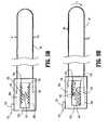
FIG. 1 is a perspective view of the optical trocar, illustrating a cannula assembly, an obturator assembly, and an endoscope;FIG. 2 is an exploded view of the handle of the obturator assembly illustrating a trigger assembly for deploying a blade and a translation mechanism for laterally translating the blade;FIG. 3 is a cross-sectional view of the distal end of an alternate obturator assembly;FIG. 4 is a side view in partial cross-section of the obturator assembly and the endoscope, illustrating the trigger assembly;FIG. 5A is an enlarged side view in partial cross-section of the trigger assembly illustrating the trigger in a non-actuated position and the translation assembly in a second or laterally translated position;FIG. 5B is an enlarged side view illustrating the mechanism for laterally translating the cutting blade, in a first or initial position.FIG. 6 is an enlarged assembled view of the distal end of the obturator assembly illustrating the interconnection between blade pusher arms and the blade;FIG. 7 is a sectional assembled view of a portion of the trigger assembly ofFIG. 2 , illustrating the cutting blade;FIG. 8 is a side view in partial cross-section of the obturator assembly and endoscope illustrating partial actuation of the trigger assembly with the blade in the non-deployed position and the translation assembly is in a first or initial condition;FIG. 9A is an enlarged side view of the trigger assembly ofFIG. 8 ;FIG. 9B is an enlarged side view of the mechanism for laterally translating the cutting blade of the apparatus ofFIGS. 8 and 9A , in a second or laterally translated condition.FIG. 10 is an enlarged view of the distal end of the obturator assembly, illustrating a dome-shaped objective optical member with the blade in the non-deployed position;FIG. 11 is a side view in partial cross-section of the obturator assembly and endoscope illustrating actuation of the trigger assembly and the blade in the deployed position;FIG. 12 is an enlarged side view of the trigger assembly;FIG. 13 is an enlarged view of the distal end of the obturator assembly, illustrating the dome-shaped objective optical member and the blade in the deployed position;FIG. 14A is an enlarged side view illustrating an alternate embodiment of a mechanism for laterally translating the cutting blade, in a first or initial position; andFIG. 14B is an enlarged side view of the mechanism for laterally translating the cutting blade of theFIG. 14 , in a second or laterally translated condition.- Embodiments of the presently disclosed optical trocar assembly will now be described in detail with reference to the drawings, in which like reference numerals designate identical or corresponding elements in each of the several views. As used herein, the term "distal" refers to that portion of the instrument, or component thereof which is further from the user while the term "proximal" refers to that point of the instrument or component thereof which is closer to the user.
- An apparatus is provided to penetrate body tissue, e.g., the abdominal wall, and to provide a simultaneous forward directional view of the body tissue being penetrated. In a preferred embodiment, shown in
FIG. 1 , the apparatus includes atrocar assembly 10 having anobturator assembly 12, acannula assembly 14, and an imaging member, such as anendoscope 16.Endoscope 16 is positioned within theobturator assembly 12 to provide observation of the body tissue being penetrated. The term obturator assembly as used herein refers to the tissue penetrating assembly of thetrocar assembly 10. - Referring to
FIGS. 1 and2 ,obturator assembly 12 includeshousing 18 and a longitudinally extendingobturator sleeve 20.Obturator housing 18 includesbarrel portion 19 andhand grip 21. Rotatably mounted toobturator housing 18 is ablade translation lever 160. The proximal end ofobturator sleeve 20 is secured withinchannel 22 ofbarrel portion 19 so that theobturator sleeve 20 extends outwardly from theobturator housing 18.Hand grip 21 is provided for manual gripping by the clinician to facilitate manipulation about the operative site. Obturator sleeve 20 has alongitudinal bore 24 which extends between the proximal end and the distal end of theobturator sleeve 20. Thelongitudinal bore 24 is configured and dimensioned to receive theendoscopic portion 26 of theendoscope 16, as shown inFIG. 1 .Housing 18 ofobturator assembly 12 is constructed of two half-sections which are joined together by welding, adhesives or the like. Aleaf spring 103 is positioned withinchannel 105 at the proximal end of thebarrel portion 19 ofhousing 18, as shown inFIG. 2 .Leaf spring 103 is provided to engageendoscopic portion 26 ofendoscope 16, to frictionally maintain the endoscope in a fixed longitudinal relationship with respect toobturator sleeve 20.- Referring to
FIGS. 2 and3 , animage passing member 28 is secured to the distal end ofobturator sleeve 20 and is provided to permit or direct images into theobturator sleeve 20 and/or to allow for the passage of illumination light from theobturator sleeve 20 to body tissue. Theimage passing member 28 may be a transparent optical window or an optical lens fabricated from a variety of materials such as polystyrene, polymethylmethacrylate (PMMA), polyurethane, transparent epoxies and/or glass or other transparent materials. The optical window shown in this preferred embodiment is hemispherical shaped, i.e., dome-shaped, and capable of allowing optical images to pass therethrough and into thelongitudinal bore 24 ofobturator sleeve 20, so as to impinge the distal end ofendoscope 16. - The objective optical member is also a dome-shaped member. However in this configuration, optical images which impinge the dome-shaped surface of objective
optical member 28 are directed intolongitudinal bore 24 ofobturator sleeve 20, so as to impinge the distal end ofendoscope 16. The objective optical member as well as the optical window is preferably configured to allow approximately a full forward angle of view. - Referring again to
FIG. 2 ,obturator assembly 12 includes acutting blade 34 operably connected to actuatingassembly 36. Cuttingblade 34 is preferably a wire, band or the like, capable of conforming to the outer surface of the dome-shapedimage passing member 28. Cuttingblade 34, or at least a portion thereof, may be sharpened or serrated 34a (FIG. 3 ) for assisting in penetration of tissue. The sharpened or serrated portion of cuttingblade 34 may be varied to correspond to the amount of lateral translation experienced by cuttingblade 34. Cuttingblade 34 interfits within an arcuate recess in the dome-shapedimage passing member 28 when in a non-deployed position. Cuttingblade 34 is preferably centered with respect to the outer surface of the image passing member as shown. Thus, in visualization, the cutting blade is seen as a thin line through the center, i.e. bisecting, the viewing field so as not to obstruct viewing of the body. - Referring now to
FIGS. 2 ,4 ,5 and6 , actuatingassembly 36 is contained withinhousing 18 and is provided to move cuttingblade 34 in general longitudinal directions between a non-deployed position (FIG. 4 ) and a deployed position (FIG. 6 ) which will be described in more detail below. As shown inFIG. 2 , the actuatingassembly 36 includes atrigger 102 slidably positioned withinchannel 104 inhousing 18 and movable between non-actuating and actuating positions.Spring 106 is secured betweenhousing 18 and trigger 102 so as to normally bias the trigger to the non-actuating position, shown inFIG. 5A .Alignment fingers trigger 102 intocorresponding channels housing 18.Alignment fingers trigger 102 withinchannel 104 ofhousing 18. - Hammer
blade drive latch 112 is secured to or extends integrally fromtrigger 102 and includes a latch release member, in the form ofpost 114.Post 114 extends between the two housing halves and intocorresponding channels 116 of each housing half, as shown inFIG. 5 .Channels 116 include alongitudinal portion 116a which permits thehammer latch 112 to engage the hammer, and asloped portion 116b which causeshammer latch 112 to disengage from the hammer, as will be described in more detail below. - Referring again to
FIGS. 2 and5 , the actuatingassembly 36 also includes blade drive members, such ashammer 120,bushing assembly 122 and a pair of drive springs 124 and 126. As shown inFIG. 5 , the hammer, bushing and drive springs are coaxially aligned withobturator sleeve 20.Drive spring 124 is positioned aboutobturator sleeve 20 withinchannel 128 of each housing half so that one end of the spring engages the housing and the other end engages the proximal end ofhammer 120.Drive spring 124 normally biases hammer 120 toward the distal end of theobturator assembly 12, indicated by arrow "A" inFIG. 5 . The proximal end ofbushing assembly 122 is positionedadjacent hammer 120 and the distal end ofbushing assembly 122 engages one end ofdrive spring 126. The other end ofdrive spring 126 engages thehousing 18, as shown.Finger 123 extending frombushing assembly 122 intochannel 125 withinhousing 18, are provided to limit the proximal and distal movement of thebushing assembly 122 and thus the proximal and distal movement ofblade 34. - Referring to
FIGS. 2 and 7 , cuttingblade 34 is positioned inslots 39 and 41 ofobturator sleeve 20. The proximal ends of cuttingblade 34 includefingers 130 extending outwardly therefrom which are configured to slide within and operatively connect tobushing assembly 122. Cuttingblade 34 may be configured for releasable engagement withbushing assembly 122. Preferably cuttingblade 34 may be replaced between procedures or as the sharpened or serrated portion becomes dull. - In addition to being configured for proximal and distal advancement of cutting
blade 34,bushing assembly 122 is further configured to permit lateral translation of cuttingblade 34 about the distal end ofobturator 20.Bushing assembly 122 comprises first andsecond housing halves second housing halves recesses Recesses bottom blade mount Second housing half 122b includes anopening 122c configured to enable access to top and bottom blade mounts 50a, 50b. - Blade mounts 50a, 50b are mirror image, semi-arcuate members having first and second opposing ends 52a, 52b, 53a, 53b, respectively. First ends 52a, 52b are configured to slideably engage one another when blade mounts 50a, 50b are assembled about
obturator 20. First ends 52a, 52b may include a tongue and groove configuration, or some other suitable method for permittingtop blade mount 50a to slide longitudinally relative tobottom blade mount 50b. First andsecond housing halves FIG. 7 ). Blade mounts 50a, 50b includeslots blade 34. - Still referring to
FIGS. 2 and 7 , in an assembled configuration, blade mounts 50a, 50b form an annular sleeve that is maintained aboutobturator 20 and withinrecesses bushing assembly 122.Slots proximal ends 130 ofwire cutting blade 34. Initially blade mounts 50a, 50b are positioned withinrecesses FIGS. 7 and9 ). In this manner, proximal ends 130 ofwire cutting blade 34 are aligned and an equal length ofblade 34 is positioned above and belowobturator 20. A toothed gear 61 mounted on ashaft 62 extends throughopening 165 formed inobturator housing 18 andopening 122c formed inbushing assembly 122 to operably engagetoothed ends Toothed gear 161 is operably connected to blade translation lever or knob 160 (FIG. 1 ) which is rotatably mounted on the exterior ofobturator housing 18. - With reference now to
FIGS. 1 and5A-5B , rotation oflever 160 in a first or clockwise direction (arrow "a") causestoothed gear 161 to rotate in the same first direction. Rotation oftoothed gear 161 causes engagement with and movement of toothed ends 53a, 53b of top andbottom blade mount toothed gear 161 rotates in the first directiontop blade mount 50a is advanced distally withinrecess 150a alongobturator 20, whilebottom blade mount 50a is advanced in the opposite or proximal direction withinrecess 150b alongobturator 20. As blade mounts 50a, 50b advance opposite one another, cuttingblade 34, operably connected thereto, is laterally translated (arrow "c") about the distal end ofobturator 20. This lateral translation of cuttingblade 34 about the distal end ofobturator 20 creates a cutting motion for encouraging penetration of tissue. Recesses bushing assembly 122 are configured to preventblade mounts Bushing assembly 122 andblade mounts blade 34. In an alternate embodiment,bushing assembly 122 may be configured to permit advancement of top and bottom blade mounts 50a, 50b in either a proximal or distal direction from the initial position. Upon complete advancement ofblade mount recesses lever 160 is prevented from further rotation in the first or clockwise direction.Lever 160 may include an indicator or be configured to show the relative position of blade mounts 50a, 50b withbushing assembly 122. Rotation oflever 160 in a second or counter-clockwise direction (arrow "b") causes blade mounts 50a, 50b to return to their initial, aligned positions (FIG. 7 and9A-9B ). In this manner, cuttingblade 34 is again laterally translated about the distal end ofobturator 20 to create a cutting motion, this time however, in the opposite direction (arrow "d").- With reference now to
FIGS. 14A and 14B , in an alternate embodiment of the mechanism for providing lateral translation ofblade 234 about the distal end ofobturator 20first blade mount 250a may be rigidly affixed withinbusing assembly 222 whilesecond blade mount 250b is permitted to laterally translate in the manner described above. Thus, astoothed gear 261 rotates and engagestoothed end 253b ofsecond blade mount 250b,second blade mount 250b is laterally translate whilefirst blade mount 250a remains stationary (FIG. 14B ).Blade 234 is configured to include aspring portion 234a for permitting lateral translation ofblade 234 in a first direction about the distal end ofobturator 20. Once the force turningtoothed gear 261 is removed,spring portion 234a of cuttingblade 234 cause the lateral retraction of blade 334. Thus,second blade mount 250b is returned to an initial position (FIG. 14A ). - Referring back to
FIGS. 8-13 , in the above configuration, movement oftrigger 102 in the proximal direction, shown by arrow "B" inFIGS. 8 and 9A , causeshammer latch 112 to retracthammer 120 and compress drive spring 124 (i.e., the hammer latch moves the hammer to a cocked or armed position).Post 114 is within thelongitudinal portion 116a ofchannel 116 andblade 34 continues to remain in the non-deployed (i.e., retracted) position within objectiveoptical member 28, as shown inFIG. 10 . Further proximal movement oftrigger 102 causes post 114 to move in a downward direction within the slopedportion 116b ofchannel 116, as shown inFIGS. 11 and 12 . Downward movement ofpost 114 causes hammerlatch 112 to disengage fromhammer 120 so thathammer 120 is thrusted distally (i.e., in the direction of arrow "C") bydrive spring 124. Ashammer 120 moves distally, the hammer engagesbushing assembly 122 and thrusts the bushing distally so as to longitudinallymove cutting blade 34 to the advanced deployed (i.e., exposed) position, as shown inFIGS. 11 and 13 . Distal movement ofbushing assembly 122 also compressesdrive spring 126 and when the biasing force ofdrive spring 126 exceeds the compression force exerted by thehammer 120,drive spring 126 automatically biases bushing 124 proximally so thatblade 34 is automatically returned to the non-deployed position. Thus, engagement ofhammer 120 andbushing assembly 122 provides substantially instantaneous deployment and retraction of the blade so the blade remains exposed for a short period of time. Thus, once the trigger is pulled to a predetermined position,blade 34 is deployed and then retracted without further action of the user (i.e., without further movement of the trigger). Housing 18 includesopening 165 to permitlever 160 andshaft 62 extending therethrough, to move relative tobushing assembly 122 during deployment and retraction ofblade 34. Thus, as cuttingblade 34 is deployed and retractedblade mounts bushing assembly 122. In an alternate embodiment,housing 18, and more particularly opening 165, andshaft 162 and/orlever 60 may be configured such that asbushing assembly 122 is deployed or retracted,shaft 62 and thus, toothed gear 61 is rotated. As described above, rotation oftoothed gear 161 causes the advancement of blade mounts 50a, 50b, thereby causing the lateral translation of cuttingblade 34. In this manner, cuttingblade 34 may both longitudinally reciprocate back and forth and translate laterally about the distal end ofobturator 20.Lever 160 andshaft 162 may further be configured for selective engagement withhousing 18, thereby permitting selective translation of cuttingblade 34 about the distal end ofobturator 20 when in either the deployed or retracted position.- In the configuration described, the
actuation assembly 36 operates in a two step manner. In the first step,trigger 102 is moved proximally to cockhammer 120. In the second step, further proximal movement oftrigger 102 causes thehammer 120 to automatically move distally to advance theblade 34 to the deployed position, and the blade is automatically returned to the non-deployed position under the force ofdrive spring 126. This two step manner automatically occurs upon fully squeezingtrigger 102. - Referring again to
FIG. 1 ,cannula assembly 14 includescannula housing 52 andcannula sleeve 54 secured to thecannula housing 52 and extending outwardly therefrom.Barrel portion 19 ofobturator housing 18 includesbushing 56 which is configured and dimensioned to interfit with the proximal end ofcannula housing 52, so thatobturator sleeve 20 coaxially aligns withcannula sleeve 54 when the two assemblies are interfitted. Thecannula sleeve 54 is adapted to remain in the body after penetration and subsequent removal of the obturator assembly 12 (and endoscope 16) to allow insertion of appropriate endoscopic/laparoscopic instrumentation therethrough. - To maintain a gas tight seal within the cannula housing, a sealing member or system may be positioned therewithin which is adapted to receive the
obturator assembly 12 of the present invention as well as other endoscopic surgical instruments. One example of a suitable sealing system utilizes a duckbill sealing member. A more detailed description of an exemplary cannula assembly and sealing system is found inU.S. Pat. No. 5,180,373 issued Jan. 19, 1993 . - Continuing to refer to
FIG. 1 ,endoscope 16 includesendoscopic portion 26 andendoscope housing 58.Endoscopic portion 26 is configured to transfer illuminating light fromendoscope housing 58 to the distal end of the endoscopic portion to provide illuminating light to the operative site. In an exemplary configuration,endoscopic portion 26 includes anouter sheath 60 and an annular array of fiberoptic elements 62 extending betweenlight source connector 64 ofendoscope housing 58 and the distal end ofouter sheath 60 to illuminate the operative site. Any known light source may be connected toconnector 64 to provide the illuminating light. Endoscopic portion 26 includes animage transferring system 66 which may include CCD's, a bundle of fiber optic elements or objective lenses which transfer an optical image received at the distal end ofendoscope 16 to eyepiece 68 for viewing. Alternatively, a video system including a monitor may be operatively connected tohousing 58 to provide a video image of the body tissue being penetrated.- Preferably, the fiber
optic elements 62 are positioned adjacent the inner wall of the outer sheath so as to surround the image transferring system. In this configuration, illumination light from the endoscope is passed through theimage passing member 28 and optical images which impinge theimage passing member 28 pass into the image transferring system and are relayed toeyepiece 68. An example of an endoscope which can be utilized is described inU.S. Pat. No. 4,964,710 . - In an alternate embodiment, the
obturator assembly 12 andendoscope 16 or optical components thereof can be a single unit inserted intocannula assembly 14. For example, the obturator assembly can be manufactured with illumination optics and/or imaging optics positioned therein so that the obturator assembly itself can function to penetrate tissue as well as to light the surgical site and transmit images to the video monitor. In this version, the obturator would not have a longitudinal bore and it would be sealed. - In operation,
endoscope 16 is inserted into thetrocar assembly 10, i.e. intolongitudinal bore 24 ofobturator sleeve 20, as shown inFIG. 4 . The surgeon then positions theblade 34 against the body tissue and repeatedly movesblade 34 by continuously squeezingtrigger 102 to automatically move theblade 34 rapidly from the nondeployed position to the deployed position and back to the non-deployed position. Pressure is applied tohand grip 21 in the distal direction to penetrate the body tissue. The movement ofblade 34 facilitates controlled cutting of the body tissue, thus permitting the surgeon to apply relatively minimal pressure to handgrip 21 to penetrate the body tissue. At the same time the surgeon may cause the lateral translation of cuttingblade 34 about the distal end ofobturator 20 by manually rotatinglever 160 in a first and second direction as described above. During penetration of the body tissue the surgeon either observes such penetration througheyepiece 68, or in instances where a video system is utilized the surgeon simply observes the penetration of the body tissue via any known video monitor. - Alternatively, the surgeon may also more selectively deploy the
blade 34 during penetration. That is, the surgeon may insert the trocar assembly and bluntly penetrate the body tissue until reaching thicker tissue, such as muscle. At this point, the blade can be deployed and/or laterally translated to penetrate (cut through) this thick tissue. When thick tissue is again encountered, the blade can be deployed and/or laterally translated again. After penetration into the body cavity, both theendoscope 16 and theobturator assembly 12 are removed from thecannula assembly 14, leaving thecannula assembly 14 in the body for insertion of desired instrumentation therethrough. - It will be understood that various modifications can be made to the embodiments herein disclosed without departing from the scope thereof. For example, various diameters for the cannula assembly, the obturator assembly, as well as various diameter endoscopes are contemplated. Also, various modifications may be made in the configuration of the trigger assembly to achieve the instantaneous deployment and retraction of the blade. Therefore, the above description should not be construed as limiting but merely as exemplifications of preferred embodiments thereof. Those skilled in the art will envision other modifications within the scope of the claims appended hereto.
Claims (13)
- An obturator (12) for penetrating tissue, which comprises :an outer member (20) defining a longitudinal axis, and having proximal and distal ends;a leading member (28) disposed adjacent the distal end of the outer member and having a tissue contacting outer surface; anda blade (34) mounted adjacent the leading member,wherein the leading member further includes an optical window adapted to permit passage of light therethrough for detection by a clinician,characterised in that the blade is adapted for at least lateral traversing movement relative to the longitudinal axis to thereby traverse the outer surface of the leading member to facilitate penetrating of tissue during advancement of the leading member within the tissue.
- The obturator according to claim 1 wherein the outer member includes a longitudinal opening adapted for reception of an endoscope.
- The obturator according to claim 1, including an imaging device associated with the outer member, the imaging device adapted to transmit an image received through the optical window.
- The obturator according to claim 1, wherein the blade is adapted for reciprocating movement along the outer surface of the leading member;
- The obturator according to claim 1, wherein the outer surface of the leading member includes a channel for at least partial reception of the blade, the blade being movable within the channel.
- The obturator according to claim 1 wherein the outer member includes an outer groove in general alignment with the channel of the leading member for at least partial reception of the blade, the blade being movable within the outer groove.
- The obturator according to claim 6 wherein the outer member includes a pair of opposed outer grooves.
- The obturator according to claim 1 wherein the blade is further adapted for longitudinal movement relative to the leading member to move between an initial position and an advanced position.
- The obturator according to claim 1 including a housing connected to the proximal end of the outer member.
- The obturator according to claim 9, including a manual actuator mounted to the housing and operatively connected to the blade, the manual actuator being dimensioned for manipulation by the clinician to cause the at least traversing movement of the blade.
- The obturator according to claim 10, wherein the blade is adapted for longitudinal movement relative to the leading member to move between an initial position and an advanced position and further including a manual advancer mounted to the housing and operatively connected to the blade, the manual advancer being dimensioned for manipulation by the clinician to move the blade between the initial position and the advanced position.
- The optical obturator according to claim 1, wherein the optical window defines a general hemispherically-shaped configuration.
- The optical obturator according to claim 8, wherein the blade at least partially extends beyond the optical window in the advanced position.
Applications Claiming Priority (2)
| Application Number | Priority Date | Filing Date | Title |
|---|---|---|---|
| US92284107P | 2007-04-11 | 2007-04-11 | |
| PCT/US2008/059342WO2008127887A1 (en) | 2007-04-11 | 2008-04-04 | Visualized entry trocar with moving blade |
Publications (3)
| Publication Number | Publication Date |
|---|---|
| EP2150186A1 EP2150186A1 (en) | 2010-02-10 |
| EP2150186A4 EP2150186A4 (en) | 2013-06-12 |
| EP2150186B1true EP2150186B1 (en) | 2015-11-11 |
Family
ID=39864298
Family Applications (1)
| Application Number | Title | Priority Date | Filing Date |
|---|---|---|---|
| EP08745070.6ANot-in-forceEP2150186B1 (en) | 2007-04-11 | 2008-04-04 | Visualized entry trocar with moving blade |
Country Status (6)
| Country | Link |
|---|---|
| US (1) | US20100048994A1 (en) |
| EP (1) | EP2150186B1 (en) |
| JP (1) | JP5437233B2 (en) |
| AU (1) | AU2008239409B2 (en) |
| CA (1) | CA2681894A1 (en) |
| WO (1) | WO2008127887A1 (en) |
Families Citing this family (13)
| Publication number | Priority date | Publication date | Assignee | Title |
|---|---|---|---|---|
| USD629899S1 (en)* | 2009-05-18 | 2010-12-28 | Karl Storz Gmbh & Co. Kg | Medical instrument |
| US20120059247A1 (en)* | 2010-09-03 | 2012-03-08 | Speeg Trevor W V | Echogenic needle for biopsy device |
| USD652923S1 (en)* | 2010-10-01 | 2012-01-24 | Viking Systems, Inc. | Endoscope |
| US9592069B2 (en) | 2012-04-28 | 2017-03-14 | Physcient, Inc. | Methods and devices for soft tissue dissection |
| MX370237B (en)* | 2012-04-28 | 2019-12-06 | Physcient Inc | Methods and devices for soft tissue dissection. |
| WO2015161249A1 (en) | 2014-04-18 | 2015-10-22 | Physcient, Inc. | Methods and devices for soft tissue dissection |
| WO2015164536A1 (en) | 2014-04-22 | 2015-10-29 | Physcient, Inc | Instruments, devices, and related methods for soft tissue dissection |
| US9835816B2 (en)* | 2015-06-10 | 2017-12-05 | Telect, Inc. | Fiber blocking kits |
| US11197687B2 (en) | 2018-08-01 | 2021-12-14 | Medtronic, Inc. | Medical tools for and methods of gaining access to extra vascular spaces |
| USD981563S1 (en)* | 2019-10-11 | 2023-03-21 | Aok Innovations, Llc | Chest tube insertion aid and handle assembly |
| US20220031390A1 (en)* | 2020-07-31 | 2022-02-03 | Medtronic, Inc. | Bipolar tool for separating tissue adhesions or tunneling |
| WO2022187871A1 (en)* | 2021-03-05 | 2022-09-09 | Rafael Holdings, Inc. | Videoscopic arthroscopic instruments, devices, and systems and methods of use and assembly |
| US11963692B2 (en) | 2021-04-30 | 2024-04-23 | Aok Innovations, Llc | Body cavity access device |
Family Cites Families (93)
| Publication number | Priority date | Publication date | Assignee | Title |
|---|---|---|---|---|
| US1727495A (en)* | 1929-09-10 | Beinhold h | ||
| US1380447A (en)* | 1919-06-14 | 1921-06-07 | Protein Products Corp | Trocar |
| US2764148A (en)* | 1950-07-11 | 1956-09-25 | Sheldon Edward Emannel | Endoscope means for the internal examination of the human body |
| US2699770A (en)* | 1951-05-11 | 1955-01-18 | Centre Nat Rech Scient | Endoscope |
| US2784149A (en)* | 1953-06-25 | 1957-03-05 | Purification of vinyl acetate | |
| US2877368A (en)* | 1954-03-11 | 1959-03-10 | Sheldon Edward Emanuel | Device for conducting images |
| US3021834A (en)* | 1954-03-11 | 1962-02-20 | Sheldon Edward Emanuel | Endoscopes |
| US3499107A (en)* | 1954-03-11 | 1970-03-03 | Sheldon Edward E | Light transfer devices using light conducting members of multilayered construction and photoelectric means |
| US3437747A (en)* | 1964-03-24 | 1969-04-08 | Sheldon Edward E | Devices for inspection using fiberoptic members |
| US3558085A (en)* | 1968-12-19 | 1971-01-26 | John W Magill | Airport surface layout |
| US3809095A (en)* | 1969-10-15 | 1974-05-07 | H Cimber | Aspirator needle injector |
| GB1356386A (en)* | 1970-06-03 | 1974-06-12 | Nat Res Dev | Artery entry tool |
| DE2157911C2 (en)* | 1970-12-11 | 1982-02-04 | Marc Edmond Jean van Bruxelles Hoorn | Surgical device for ligating internal structures |
| DK131542C (en)* | 1974-02-06 | 1976-02-09 | Akad Tekn Videnskaber | SURGICAL INSTRUMENT FOR SAMPLING BIOLOGICAL SAMPLES |
| US3915169A (en)* | 1974-11-14 | 1975-10-28 | George Mcguire | Surgical knife having malleable shank |
| US4269192A (en)* | 1977-12-02 | 1981-05-26 | Olympus Optical Co., Ltd. | Stabbing apparatus for diagnosis of living body |
| US4220155A (en)* | 1978-05-11 | 1980-09-02 | Colorado State University Research Foundation | Apparatus for spaying large animals |
| US4210146A (en)* | 1978-06-01 | 1980-07-01 | Anton Banko | Surgical instrument with flexible blade |
| GB2048686B (en)* | 1979-05-15 | 1983-03-16 | Wolf Gmbh Richard | Endoscopc instrumentation apparatus |
| US4256119A (en)* | 1979-09-17 | 1981-03-17 | Gauthier Industries, Inc. | Biopsy needle |
| US4254762A (en)* | 1979-10-23 | 1981-03-10 | Inbae Yoon | Safety endoscope system |
| US4461305A (en)* | 1981-09-04 | 1984-07-24 | Cibley Leonard J | Automated biopsy device |
| US4411653A (en)* | 1982-01-28 | 1983-10-25 | Razi M Dean | Cannula introducer |
| US4516575A (en)* | 1982-06-03 | 1985-05-14 | Coopervision, Inc. | Surgical scalpel |
| US4601710B1 (en)* | 1983-08-24 | 1998-05-05 | United States Surgical Corp | Trocar assembly |
| US4539976A (en)* | 1984-02-08 | 1985-09-10 | Sharpe Jewett M | Endoscopic surgical instrument |
| JPS60179057A (en)* | 1984-02-28 | 1985-09-12 | 雪印乳業株式会社 | Fertilized egg transplantation triple needle for laparoscope |
| US4570632A (en)* | 1984-03-16 | 1986-02-18 | Woods Randall L | Cystotome for eye surgery and method of opening lens capsule |
| US4667684A (en)* | 1985-02-08 | 1987-05-26 | Bio-Medical Resources, Inc. | Biopsy device |
| US4723545A (en)* | 1986-02-03 | 1988-02-09 | Graduate Hospital Foundation Research Corporation | Power assisted arthroscopic surgical device |
| US4865029A (en)* | 1986-04-24 | 1989-09-12 | Eye Research Institute Of Retina Foundation | Endophotocoagulation probe |
| US4991269A (en)* | 1987-03-13 | 1991-02-12 | Akitada Kuroda | Clip |
| US4733671A (en)* | 1987-03-17 | 1988-03-29 | Mehl Donald N | Tissue needle |
| US5089000A (en)* | 1987-09-18 | 1992-02-18 | John M. Agee | Surgical method and instrument therefor |
| US4962770A (en)* | 1987-09-18 | 1990-10-16 | John M. Agee | Surgical method |
| US4957112A (en)* | 1987-11-20 | 1990-09-18 | Olympus Optical Co., Ltd. | Ultrasonic diagnostic apparatus |
| US5146921A (en)* | 1987-11-27 | 1992-09-15 | Vance Products Inc. | Biopsy instrument stylet and cannula assembly |
| US4904246A (en)* | 1988-07-19 | 1990-02-27 | Snyder Laboratories, Inc. | Cannula assembly |
| US5092872A (en)* | 1989-07-28 | 1992-03-03 | Jacob Segalowitz | Valvulotome catheter |
| US5007481A (en)* | 1990-02-02 | 1991-04-16 | Exxon Chemical Patents, Inc. | Method of treating subterranean formations using a non-damaging fracturing fluid |
| US5116353B1 (en)* | 1990-10-05 | 1996-09-10 | Digital Voice Systems Inc | Safety trocar |
| DE4035146A1 (en)* | 1990-11-06 | 1992-05-07 | Riek Siegfried | INSTRUMENT FOR PENETRATING BODY TISSUE |
| US5250068A (en)* | 1990-11-30 | 1993-10-05 | Yakuouji Shinkiyu Chiryouin | Optical transmission type acupuncture needle |
| US5104382A (en)* | 1991-01-15 | 1992-04-14 | Ethicon, Inc. | Trocar |
| US5152754A (en)* | 1991-02-15 | 1992-10-06 | Minnesota Mining And Manufacturing Company | Trocar |
| US5183053A (en)* | 1991-04-12 | 1993-02-02 | Acuderm, Inc. | Elliptical biopsy punch |
| US5591186A (en)* | 1991-05-22 | 1997-01-07 | Wurster; Helmut | Self-cutting trocar |
| US5176695A (en)* | 1991-07-08 | 1993-01-05 | Davinci Medical, Inc. | Surgical cutting means |
| US5158552A (en)* | 1991-11-04 | 1992-10-27 | American Cyanamid Company | Safety trocar instrument having a retractable trocar actuated by relief of pressure on the trocar point |
| US5188176A (en)* | 1991-11-08 | 1993-02-23 | Atlantic Richfield Company | Cement slurries for diviated wells |
| US5290276A (en)* | 1992-02-06 | 1994-03-01 | Sewell Jr Frank | Rotatable laparoscopic puncturing instrument |
| DE4229310A1 (en)* | 1992-09-02 | 1994-03-10 | Winter & Ibe Olympus | Medical instrument for creating a tissue channel |
| US5275583A (en)* | 1992-10-05 | 1994-01-04 | Lawrence Crainich | Trocar assembly with independently acting shield means |
| US5354302A (en)* | 1992-11-06 | 1994-10-11 | Ko Sung Tao | Medical device and method for facilitating intra-tissue visual observation and manipulation of distensible tissues |
| US5562696A (en)* | 1992-11-12 | 1996-10-08 | Cordis Innovasive Systems, Inc. | Visualization trocar |
| US5385572A (en)* | 1992-11-12 | 1995-01-31 | Beowulf Holdings | Trocar for endoscopic surgery |
| US5334150A (en)* | 1992-11-17 | 1994-08-02 | Kaali Steven G | Visually directed trocar for laparoscopic surgical procedures and method of using same |
| US5314417A (en)* | 1992-12-22 | 1994-05-24 | Ethicon, Inc. | Safety trocar |
| US5731804A (en)* | 1995-01-18 | 1998-03-24 | Immersion Human Interface Corp. | Method and apparatus for providing high bandwidth, low noise mechanical I/O for computer systems |
| US5441041A (en)* | 1993-09-13 | 1995-08-15 | United States Surgical Corporation | Optical trocar |
| US5467762A (en)* | 1993-09-13 | 1995-11-21 | United States Surgical Corporation | Optical trocar |
| US5720761A (en)* | 1993-11-16 | 1998-02-24 | Worldwide Optical Trocar Licensing Corp. | Visually directed trocar and method |
| US5609562A (en)* | 1993-11-16 | 1997-03-11 | Worldwide Optical Trocar Licensing Corporation | Visually directed trocar and method |
| US5445142A (en)* | 1994-03-15 | 1995-08-29 | Ethicon Endo-Surgery, Inc. | Surgical trocars having optical tips defining one or more viewing ports |
| CA2149290C (en)* | 1994-05-26 | 2006-07-18 | Carl T. Urban | Optical trocar |
| US5658306A (en)* | 1994-07-01 | 1997-08-19 | Archimedes Surgical, Inc. | Method for making additional incisions in laparoscopic surgery |
| US5632717A (en)* | 1994-10-07 | 1997-05-27 | Yoon; Inbae | Penetrating endoscope |
| US5591192A (en)* | 1995-02-01 | 1997-01-07 | Ethicon Endo-Surgery, Inc. | Surgical penetration instrument including an imaging element |
| US5569291A (en)* | 1995-02-01 | 1996-10-29 | Ethicon Endo-Surgery, Inc. | Surgical penetration and dissection instrument |
| US5662673A (en)* | 1995-04-05 | 1997-09-02 | Kieturakis; Maciej J. | Surgical trocar and method for placing a trocar sleeve in a body wall |
| AU2666097A (en)* | 1996-04-10 | 1997-10-29 | Endoscopic Technologies, Inc. | Improving visualization during closed-chest surgery |
| DE19626408A1 (en)* | 1996-07-01 | 1998-01-08 | Berchtold Gmbh & Co Geb | Trocar for laparoscopic operations |
| US6039748A (en)* | 1997-08-05 | 2000-03-21 | Femrx, Inc. | Disposable laparoscopic morcellator |
| US6447527B1 (en)* | 1998-04-23 | 2002-09-10 | Ronald J. Thompson | Apparatus and methods for the penetration of tissue |
| US6030402A (en)* | 1998-04-23 | 2000-02-29 | Thompson; Ronald J. | Apparatus and methods for the penetration of tissue, and the creation of an opening therein |
| US6056766A (en)* | 1998-06-09 | 2000-05-02 | Thompson; Ronald J. | Stabilized trocar, and method of using same |
| US6319266B1 (en)* | 2000-03-16 | 2001-11-20 | United States Surgical Corporation | Trocar system and method of use |
| DE60140278D1 (en)* | 2000-08-08 | 2009-12-03 | Tyco Healthcare | Shaped trocar seal |
| US7544206B2 (en)* | 2001-06-29 | 2009-06-09 | Medtronic, Inc. | Method and apparatus for resecting and replacing an aortic valve |
| US6602267B2 (en)* | 2001-10-17 | 2003-08-05 | Medcanica, Inc. | Articulable and reciprocable surgical knife |
| US6916328B2 (en)* | 2001-11-15 | 2005-07-12 | Expanding Concepts, L.L.C | Percutaneous cellulite removal system |
| USD518177S1 (en)* | 2002-03-08 | 2006-03-28 | Erblan Surgical, Inc. | Safety trocar with progressive cutting tip guards and gas jet tissue deflector |
| US6939341B2 (en)* | 2002-06-28 | 2005-09-06 | Dutch Opthalmic Research Center (D.O.R.C.) | Surgical cutting tool |
| US7056329B2 (en)* | 2002-10-23 | 2006-06-06 | Intellimed Surgical Solutions, Llc | Laparoscopic direct vision dissecting port |
| US7041115B2 (en)* | 2002-11-18 | 2006-05-09 | A.M. Surgical, Inc. | Endoscopic surgical procedure |
| US7811293B2 (en)* | 2003-01-31 | 2010-10-12 | Philip J. Simpson | System and method for rapid placement of chest tubes |
| US7481817B2 (en)* | 2003-02-13 | 2009-01-27 | Lsi Soultions, Inc. | Instrument for surgically cutting tissue and method of use |
| USD517694S1 (en)* | 2003-08-12 | 2006-03-21 | Erblan Surgical, Inc | Tip portion of an infusor |
| EP2545862B1 (en)* | 2003-10-03 | 2015-09-30 | Applied Medical Resources Corporation | Bladeless optical obturator with a lock for an optical instrument |
| US7329279B2 (en)* | 2003-12-23 | 2008-02-12 | Sadra Medical, Inc. | Methods and apparatus for endovascularly replacing a patient's heart valve |
| US7988670B2 (en)* | 2005-06-30 | 2011-08-02 | Tyco Healthcare Group Lp | Trocar assembly with rotatable obturator housing |
| US7524331B2 (en)* | 2006-04-06 | 2009-04-28 | Medtronic Vascular, Inc. | Catheter delivered valve having a barrier to provide an enhanced seal |
| EP1875874B1 (en)* | 2006-07-06 | 2013-02-27 | Covidien LP | Two mode trocar assembly |
- 2008
- 2008-04-04AUAU2008239409Apatent/AU2008239409B2/ennot_activeCeased
- 2008-04-04JPJP2010503129Apatent/JP5437233B2/ennot_activeExpired - Fee Related
- 2008-04-04EPEP08745070.6Apatent/EP2150186B1/ennot_activeNot-in-force
- 2008-04-04WOPCT/US2008/059342patent/WO2008127887A1/enactiveApplication Filing
- 2008-04-04USUS12/594,609patent/US20100048994A1/ennot_activeAbandoned
- 2008-04-04CACA002681894Apatent/CA2681894A1/ennot_activeAbandoned
Also Published As
| Publication number | Publication date |
|---|---|
| JP2010523272A (en) | 2010-07-15 |
| AU2008239409A1 (en) | 2008-10-23 |
| WO2008127887A1 (en) | 2008-10-23 |
| US20100048994A1 (en) | 2010-02-25 |
| EP2150186A4 (en) | 2013-06-12 |
| CA2681894A1 (en) | 2008-10-23 |
| JP5437233B2 (en) | 2014-03-12 |
| AU2008239409B2 (en) | 2013-09-19 |
| EP2150186A1 (en) | 2010-02-10 |
Similar Documents
| Publication | Publication Date | Title |
|---|---|---|
| EP2150186B1 (en) | Visualized entry trocar with moving blade | |
| US5860996A (en) | Optical trocar | |
| EP0642764B1 (en) | Optical Trocar | |
| US5441041A (en) | Optical trocar | |
| JP5248596B2 (en) | Visualization obturator with handle | |
| US8192353B2 (en) | Visual obturator | |
| US7470230B2 (en) | Optical obturator |
Legal Events
| Date | Code | Title | Description |
|---|---|---|---|
| PUAI | Public reference made under article 153(3) epc to a published international application that has entered the european phase | Free format text:ORIGINAL CODE: 0009012 | |
| 17P | Request for examination filed | Effective date:20091111 | |
| AK | Designated contracting states | Kind code of ref document:A1 Designated state(s):AT BE BG CH CY CZ DE DK EE ES FI FR GB GR HR HU IE IS IT LI LT LU LV MC MT NL NO PL PT RO SE SI SK TR | |
| AX | Request for extension of the european patent | Extension state:AL BA MK RS | |
| DAX | Request for extension of the european patent (deleted) | ||
| RAP1 | Party data changed (applicant data changed or rights of an application transferred) | Owner name:COVIDIEN LP | |
| A4 | Supplementary search report drawn up and despatched | Effective date:20130514 | |
| RIC1 | Information provided on ipc code assigned before grant | Ipc:A61B 17/32 20060101ALN20130507BHEP Ipc:A61B 17/34 20060101AFI20130507BHEP | |
| GRAP | Despatch of communication of intention to grant a patent | Free format text:ORIGINAL CODE: EPIDOSNIGR1 | |
| RIC1 | Information provided on ipc code assigned before grant | Ipc:A61B 17/32 20060101ALN20150512BHEP Ipc:A61B 17/34 20060101AFI20150512BHEP | |
| INTG | Intention to grant announced | Effective date:20150610 | |
| GRAS | Grant fee paid | Free format text:ORIGINAL CODE: EPIDOSNIGR3 | |
| GRAA | (expected) grant | Free format text:ORIGINAL CODE: 0009210 | |
| AK | Designated contracting states | Kind code of ref document:B1 Designated state(s):AT BE BG CH CY CZ DE DK EE ES FI FR GB GR HR HU IE IS IT LI LT LU LV MC MT NL NO PL PT RO SE SI SK TR | |
| REG | Reference to a national code | Ref country code:GB Ref legal event code:FG4D | |
| REG | Reference to a national code | Ref country code:CH Ref legal event code:EP | |
| REG | Reference to a national code | Ref country code:IE Ref legal event code:FG4D | |
| REG | Reference to a national code | Ref country code:AT Ref legal event code:REF Ref document number:760033 Country of ref document:AT Kind code of ref document:T Effective date:20151215 | |
| REG | Reference to a national code | Ref country code:DE Ref legal event code:R096 Ref document number:602008041128 Country of ref document:DE | |
| REG | Reference to a national code | Ref country code:LT Ref legal event code:MG4D | |
| REG | Reference to a national code | Ref country code:NL Ref legal event code:MP Effective date:20160211 | |
| REG | Reference to a national code | Ref country code:FR Ref legal event code:PLFP Year of fee payment:9 | |
| REG | Reference to a national code | Ref country code:AT Ref legal event code:MK05 Ref document number:760033 Country of ref document:AT Kind code of ref document:T Effective date:20151111 | |
| PG25 | Lapsed in a contracting state [announced via postgrant information from national office to epo] | Ref country code:IS Free format text:LAPSE BECAUSE OF FAILURE TO SUBMIT A TRANSLATION OF THE DESCRIPTION OR TO PAY THE FEE WITHIN THE PRESCRIBED TIME-LIMIT Effective date:20160311 Ref country code:NO Free format text:LAPSE BECAUSE OF FAILURE TO SUBMIT A TRANSLATION OF THE DESCRIPTION OR TO PAY THE FEE WITHIN THE PRESCRIBED TIME-LIMIT Effective date:20160211 Ref country code:HR Free format text:LAPSE BECAUSE OF FAILURE TO SUBMIT A TRANSLATION OF THE DESCRIPTION OR TO PAY THE FEE WITHIN THE PRESCRIBED TIME-LIMIT Effective date:20151111 Ref country code:ES Free format text:LAPSE BECAUSE OF FAILURE TO SUBMIT A TRANSLATION OF THE DESCRIPTION OR TO PAY THE FEE WITHIN THE PRESCRIBED TIME-LIMIT Effective date:20151111 Ref country code:IT Free format text:LAPSE BECAUSE OF FAILURE TO SUBMIT A TRANSLATION OF THE DESCRIPTION OR TO PAY THE FEE WITHIN THE PRESCRIBED TIME-LIMIT Effective date:20151111 Ref country code:LT Free format text:LAPSE BECAUSE OF FAILURE TO SUBMIT A TRANSLATION OF THE DESCRIPTION OR TO PAY THE FEE WITHIN THE PRESCRIBED TIME-LIMIT Effective date:20151111 Ref country code:NL Free format text:LAPSE BECAUSE OF FAILURE TO SUBMIT A TRANSLATION OF THE DESCRIPTION OR TO PAY THE FEE WITHIN THE PRESCRIBED TIME-LIMIT Effective date:20151111 | |
| PG25 | Lapsed in a contracting state [announced via postgrant information from national office to epo] | Ref country code:PT Free format text:LAPSE BECAUSE OF FAILURE TO SUBMIT A TRANSLATION OF THE DESCRIPTION OR TO PAY THE FEE WITHIN THE PRESCRIBED TIME-LIMIT Effective date:20160311 Ref country code:FI Free format text:LAPSE BECAUSE OF FAILURE TO SUBMIT A TRANSLATION OF THE DESCRIPTION OR TO PAY THE FEE WITHIN THE PRESCRIBED TIME-LIMIT Effective date:20151111 Ref country code:LV Free format text:LAPSE BECAUSE OF FAILURE TO SUBMIT A TRANSLATION OF THE DESCRIPTION OR TO PAY THE FEE WITHIN THE PRESCRIBED TIME-LIMIT Effective date:20151111 Ref country code:AT Free format text:LAPSE BECAUSE OF FAILURE TO SUBMIT A TRANSLATION OF THE DESCRIPTION OR TO PAY THE FEE WITHIN THE PRESCRIBED TIME-LIMIT Effective date:20151111 Ref country code:GR Free format text:LAPSE BECAUSE OF FAILURE TO SUBMIT A TRANSLATION OF THE DESCRIPTION OR TO PAY THE FEE WITHIN THE PRESCRIBED TIME-LIMIT Effective date:20160212 Ref country code:SE Free format text:LAPSE BECAUSE OF FAILURE TO SUBMIT A TRANSLATION OF THE DESCRIPTION OR TO PAY THE FEE WITHIN THE PRESCRIBED TIME-LIMIT Effective date:20151111 Ref country code:PL Free format text:LAPSE BECAUSE OF FAILURE TO SUBMIT A TRANSLATION OF THE DESCRIPTION OR TO PAY THE FEE WITHIN THE PRESCRIBED TIME-LIMIT Effective date:20151111 | |
| PG25 | Lapsed in a contracting state [announced via postgrant information from national office to epo] | Ref country code:CZ Free format text:LAPSE BECAUSE OF FAILURE TO SUBMIT A TRANSLATION OF THE DESCRIPTION OR TO PAY THE FEE WITHIN THE PRESCRIBED TIME-LIMIT Effective date:20151111 | |
| REG | Reference to a national code | Ref country code:DE Ref legal event code:R097 Ref document number:602008041128 Country of ref document:DE | |
| PG25 | Lapsed in a contracting state [announced via postgrant information from national office to epo] | Ref country code:EE Free format text:LAPSE BECAUSE OF FAILURE TO SUBMIT A TRANSLATION OF THE DESCRIPTION OR TO PAY THE FEE WITHIN THE PRESCRIBED TIME-LIMIT Effective date:20151111 Ref country code:SK Free format text:LAPSE BECAUSE OF FAILURE TO SUBMIT A TRANSLATION OF THE DESCRIPTION OR TO PAY THE FEE WITHIN THE PRESCRIBED TIME-LIMIT Effective date:20151111 Ref country code:DK Free format text:LAPSE BECAUSE OF FAILURE TO SUBMIT A TRANSLATION OF THE DESCRIPTION OR TO PAY THE FEE WITHIN THE PRESCRIBED TIME-LIMIT Effective date:20151111 Ref country code:RO Free format text:LAPSE BECAUSE OF FAILURE TO SUBMIT A TRANSLATION OF THE DESCRIPTION OR TO PAY THE FEE WITHIN THE PRESCRIBED TIME-LIMIT Effective date:20151111 Ref country code:BE Free format text:LAPSE BECAUSE OF NON-PAYMENT OF DUE FEES Effective date:20160430 | |
| PLBE | No opposition filed within time limit | Free format text:ORIGINAL CODE: 0009261 | |
| STAA | Information on the status of an ep patent application or granted ep patent | Free format text:STATUS: NO OPPOSITION FILED WITHIN TIME LIMIT | |
| 26N | No opposition filed | Effective date:20160812 | |
| PG25 | Lapsed in a contracting state [announced via postgrant information from national office to epo] | Ref country code:SI Free format text:LAPSE BECAUSE OF FAILURE TO SUBMIT A TRANSLATION OF THE DESCRIPTION OR TO PAY THE FEE WITHIN THE PRESCRIBED TIME-LIMIT Effective date:20151111 | |
| REG | Reference to a national code | Ref country code:CH Ref legal event code:PL | |
| PG25 | Lapsed in a contracting state [announced via postgrant information from national office to epo] | Ref country code:BE Free format text:LAPSE BECAUSE OF FAILURE TO SUBMIT A TRANSLATION OF THE DESCRIPTION OR TO PAY THE FEE WITHIN THE PRESCRIBED TIME-LIMIT Effective date:20151111 Ref country code:LU Free format text:LAPSE BECAUSE OF FAILURE TO SUBMIT A TRANSLATION OF THE DESCRIPTION OR TO PAY THE FEE WITHIN THE PRESCRIBED TIME-LIMIT Effective date:20160404 | |
| PG25 | Lapsed in a contracting state [announced via postgrant information from national office to epo] | Ref country code:CH Free format text:LAPSE BECAUSE OF NON-PAYMENT OF DUE FEES Effective date:20160430 Ref country code:LI Free format text:LAPSE BECAUSE OF NON-PAYMENT OF DUE FEES Effective date:20160430 | |
| REG | Reference to a national code | Ref country code:FR Ref legal event code:PLFP Year of fee payment:10 | |
| PGFP | Annual fee paid to national office [announced via postgrant information from national office to epo] | Ref country code:FR Payment date:20170322 Year of fee payment:10 | |
| PGFP | Annual fee paid to national office [announced via postgrant information from national office to epo] | Ref country code:IE Payment date:20170323 Year of fee payment:10 Ref country code:GB Payment date:20170324 Year of fee payment:10 | |
| PGFP | Annual fee paid to national office [announced via postgrant information from national office to epo] | Ref country code:DE Payment date:20170321 Year of fee payment:10 | |
| PG25 | Lapsed in a contracting state [announced via postgrant information from national office to epo] | Ref country code:HU Free format text:LAPSE BECAUSE OF FAILURE TO SUBMIT A TRANSLATION OF THE DESCRIPTION OR TO PAY THE FEE WITHIN THE PRESCRIBED TIME-LIMIT; INVALID AB INITIO Effective date:20080404 Ref country code:CY Free format text:LAPSE BECAUSE OF FAILURE TO SUBMIT A TRANSLATION OF THE DESCRIPTION OR TO PAY THE FEE WITHIN THE PRESCRIBED TIME-LIMIT Effective date:20151111 | |
| PG25 | Lapsed in a contracting state [announced via postgrant information from national office to epo] | Ref country code:MC Free format text:LAPSE BECAUSE OF FAILURE TO SUBMIT A TRANSLATION OF THE DESCRIPTION OR TO PAY THE FEE WITHIN THE PRESCRIBED TIME-LIMIT Effective date:20151111 Ref country code:MT Free format text:LAPSE BECAUSE OF NON-PAYMENT OF DUE FEES Effective date:20160430 Ref country code:TR Free format text:LAPSE BECAUSE OF FAILURE TO SUBMIT A TRANSLATION OF THE DESCRIPTION OR TO PAY THE FEE WITHIN THE PRESCRIBED TIME-LIMIT Effective date:20151111 | |
| PG25 | Lapsed in a contracting state [announced via postgrant information from national office to epo] | Ref country code:BG Free format text:LAPSE BECAUSE OF FAILURE TO SUBMIT A TRANSLATION OF THE DESCRIPTION OR TO PAY THE FEE WITHIN THE PRESCRIBED TIME-LIMIT Effective date:20151111 | |
| REG | Reference to a national code | Ref country code:DE Ref legal event code:R119 Ref document number:602008041128 Country of ref document:DE | |
| GBPC | Gb: european patent ceased through non-payment of renewal fee | Effective date:20180404 | |
| REG | Reference to a national code | Ref country code:IE Ref legal event code:MM4A | |
| PG25 | Lapsed in a contracting state [announced via postgrant information from national office to epo] | Ref country code:DE Free format text:LAPSE BECAUSE OF NON-PAYMENT OF DUE FEES Effective date:20181101 | |
| PG25 | Lapsed in a contracting state [announced via postgrant information from national office to epo] | Ref country code:GB Free format text:LAPSE BECAUSE OF NON-PAYMENT OF DUE FEES Effective date:20180404 | |
| PG25 | Lapsed in a contracting state [announced via postgrant information from national office to epo] | Ref country code:IE Free format text:LAPSE BECAUSE OF NON-PAYMENT OF DUE FEES Effective date:20180404 Ref country code:FR Free format text:LAPSE BECAUSE OF NON-PAYMENT OF DUE FEES Effective date:20180430 |